Method, Apparatus And System For A Water Jet
Alvarez; Jeffery B. ; et al.
U.S. patent application number 16/257980 was filed with the patent office on 2019-05-23 for method, apparatus and system for a water jet. The applicant listed for this patent is Auris Health, Inc.. Invention is credited to Jeffery B. Alvarez, David Mintz.
| Application Number | 20190151148 16/257980 |
| Document ID | / |
| Family ID | 51687292 |
| Filed Date | 2019-05-23 |
View All Diagrams
| United States Patent Application | 20190151148 |
| Kind Code | A1 |
| Alvarez; Jeffery B. ; et al. | May 23, 2019 |
METHOD, APPARATUS AND SYSTEM FOR A WATER JET
Abstract
A water jet instrument may be used for manually performing surgery. The water jet instrument may be manually controlled or controlled by a system with a robotic control. The water jet apparatus defines a jet cutting area that is based at least in part on a flow rate meter and a feedback loop.
| Inventors: | Alvarez; Jeffery B.; (Redwood City, CA) ; Mintz; David; (Mountain View, CA) | ||||||||||
| Applicant: |
|
||||||||||
|---|---|---|---|---|---|---|---|---|---|---|---|
| Family ID: | 51687292 | ||||||||||
| Appl. No.: | 16/257980 | ||||||||||
| Filed: | January 25, 2019 |
Related U.S. Patent Documents
| Application Number | Filing Date | Patent Number | ||
|---|---|---|---|---|
| 14158548 | Jan 17, 2014 | 10231867 | ||
| 16257980 | ||||
| 61754426 | Jan 18, 2013 | |||
| Current U.S. Class: | 1/1 |
| Current CPC Class: | A61B 17/3203 20130101; A61B 34/30 20160201; A61F 9/00736 20130101 |
| International Class: | A61F 9/007 20060101 A61F009/007; A61B 17/3203 20060101 A61B017/3203; A61B 34/30 20060101 A61B034/30 |
Claims
1. A medical method comprising: providing a water jet system, wherein the water jet system comprises a water jet fluid flush tube and an aspiration tube, wherein the water jet fluid flush tube and the aspiration tube are adjacently disposed relative to one another; endoscopically inserting the water jet system into a patient; applying fluid from the water jet flush tube to create a cutting jet area to break apart tissue; and using the adjacently aspiration tube to remove the broken apart tissue via aspiration.
2. The medical method of claim 1, wherein during aspiration, a distal tip of the aspiration tube is not aligned with a distal tip of the water jet fluid tube.
3. The medical method of claim 1, further comprising attaching the water jet system to an arm.
4. The medical method of claim 3, wherein the arm is a robotic arm.
5. The medical method of claim 4, wherein the robotic arm is coupled to the water jet system via an instrument drive mechanism.
6. The medical method of claim 1, wherein the cutting jet area is controlled at least in part on a flow rate meter.
7. The medical method of claim 6, wherein the flow rate meter utilizes a feedback loop to a pump, wherein the feedback loop is controlled by a central processing unit.
8. The medical method of claim 1, wherein the water jet system is manually controlled.
9. The medical method of claim 1, wherein the fluid comprises a saline solution.
10. The medical method of claim 1, wherein the water jet system comprises a central processing unit for controlling the aspiration tube.
11. The medical method of claim 1, further comprising moderating a flow of the fluid from the water jet flush tube based on a measured aspiration flow of the aspiration tube.
12. The medical method of claim 11, wherein moderating the flow is based on a throttle valve or pump control.
13. A medical method comprising: providing a water jet system, wherein the water jet system comprises a water jet fluid flush tube and an aspiration tube, wherein the water jet fluid flush tube and the aspiration tube are adjacently disposed relative to one another; endoscopically inserting the water jet system into a patient; utilizing ultrasound to localize the water jet system within the patient; applying fluid from the water jet flush tube to create a cutting jet area to break apart tissue; using the adjacently aspiration tube to remove the broken apart tissue via aspiration.
14. The medical method of claim 13, further comprising attaching the water jet system to an arm.
15. The medical method of claim 14, wherein the arm is a robotic arm.
16. The medical method of claim 15, wherein the robotic arm is coupled to the water jet system via an instrument drive mechanism.
17. The medical method of claim 13, wherein the cutting jet area is controlled at least in part on a flow rate meter.
18. The medical method of claim 17, wherein the flow rate meter utilizes a feedback loop to a pump, wherein the feedback loop is controlled by a central processing unit.
19. The medical method of claim 13, further comprising moderating a flow of the fluid from the water jet flush tube based on a measured aspiration flow of the aspiration tube.
20. The medical method of claim 19, wherein moderating the flow is based on a throttle valve or pump control.
Description
CROSS-REFERENCE TO RELATED APPLICATIONS
[0001] This application is a continuation of U.S. patent application Ser. No. 14/158,548 filed Jan. 17, 2014, which claims the benefit of U.S. Provisional Application No. 61/754,426, filed Jan. 18, 2013, the entire contents of which are incorporated herein by reference in their entirety.
BACKGROUND OF THE INVENTION
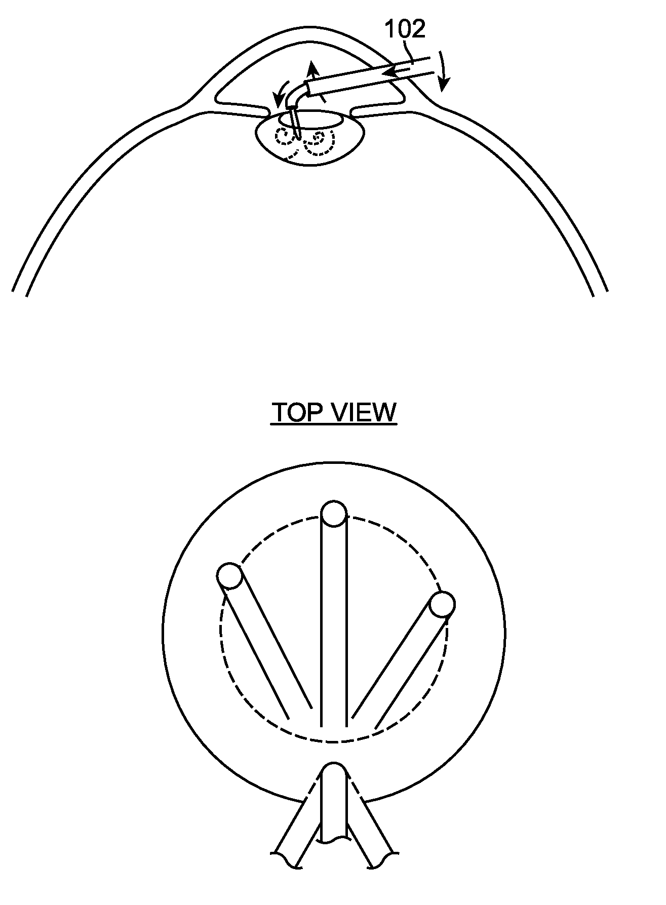
1. Field of the Invention
[0002] The field of the present application pertains to medical devices. More particularly, the field of the invention pertains to an apparatus, system, and method for performing surgery.
2. Description of the Background Art
[0003] A cataract is a clouding of the lens in the eye that affects vision. Most cataracts are related to aging. Cataracts are very common in older people. By age 80, more than half of all Americans either have a cataract or have had cataract surgery.
[0004] The lens lies behind the iris and the pupil. It works much like a camera lens. It focuses light onto the retina at the back of the eye, where an image is recorded. The lens also adjusts the eye's focus, letting us see things clearly both up close and far away. The lens is made of mostly water and protein. The protein is arranged in a precise way that keeps the lens clear and lets light pass through it. But as we age, some of the protein may clump together and start to cloud a small area of the lens. This is a cataract. Over time, the cataract may grow larger and cloud more of the lens, making it harder to see.
[0005] Age-related cataracts can affect vision in two ways. First, clumps of protein reduce the sharpness of the image reaching the retina. The lens consists mostly of water and protein. When the protein clumps up, it clouds the lens and reduces the light that reaches the retina. The clouding may become severe enough to cause blurred vision. Most age-related cataracts develop from protein clumping. Second, the clear lens slowly changes to a yellowish/brownish color, adding a brownish tint to vision. As the clear lens slowly colors with age, it may gradually cause vision to have a brownish shade. At first, the amount of tinting may be small and may not cause a vision problem. Over time, increased tinting may make it more difficult to read and perform other routine activities.
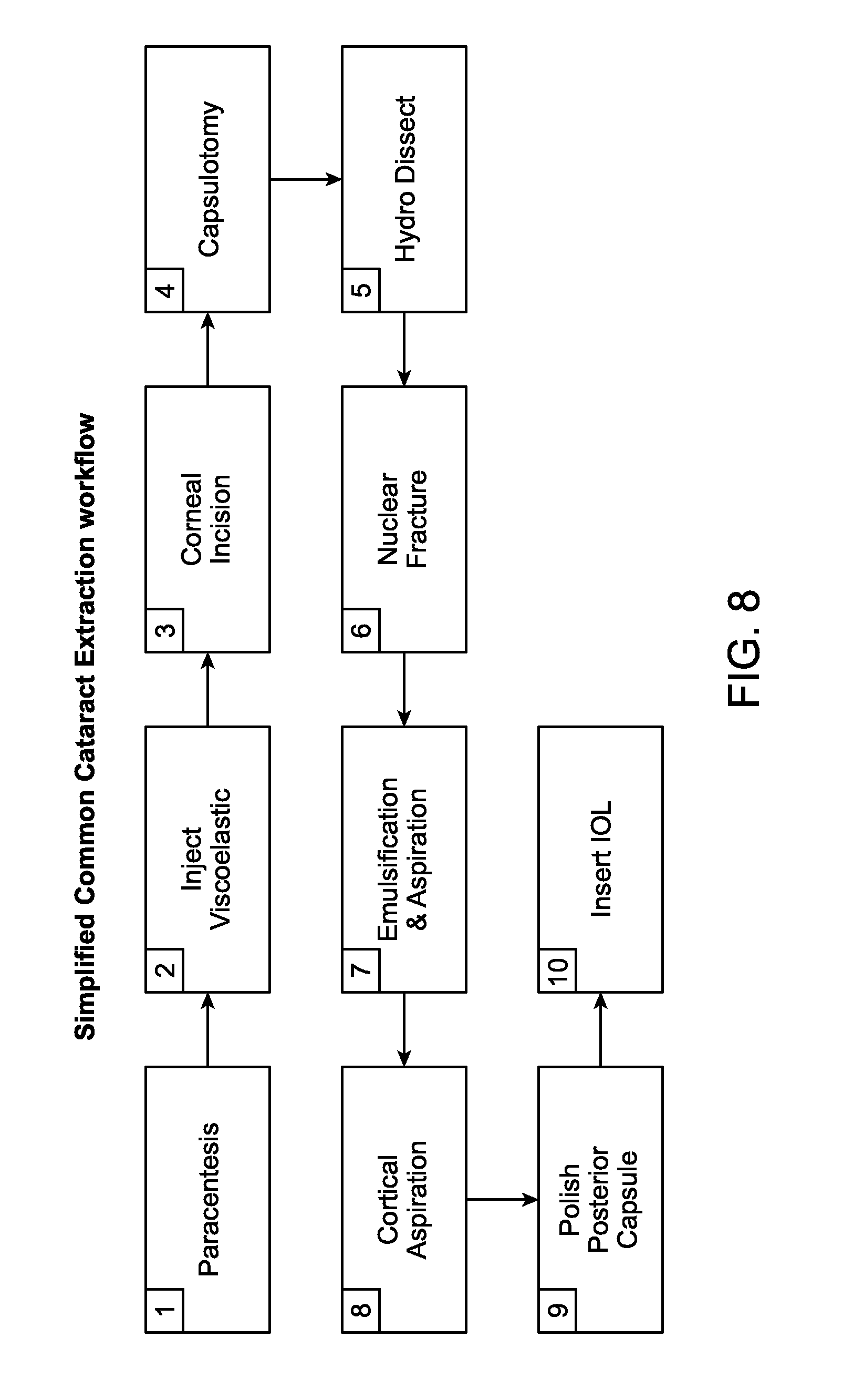
[0006] Surgery is the only real treatment for cataracts. Each year, cataract surgeons in the United States perform over three million cataract surgeries. One of the more conventional cataract surgery procedures is called extracapsular cataract extraction (ECCE). Extracapsular cataract extraction involves the removal of almost the entire natural lens while the elastic lens capsule (posterior capsule) is left intact to allow implantation of an intraocular lens. It involves manual expression of the lens through a large (usually 10-12 mm) incision made in the cornea or sclera. Although it requires a larger incision and the use of stitches, the conventional method may be indicated for patients with very hard cataracts or other situations in which phacoemulsification is problematic.
[0007] Modern cataract surgery is usually performed using a microsurgical technique called phacoemulsfication, whereby the cataract is emulsified with an ultrasonic handpiece and then suctioned out of the eye. Before phacoemulsification can be performed, one or more incisions are made in the eye to allow the introduction of surgical instruments. The surgeon then removes the anterior face of the capsule that contains the lens inside the eye. A phacoemulsification probe is an ultrasonic handpiece with a titanium or steel needle. The tip of the needle vibrates at ultrasonic frequency to sculpt and emulsify the cataract while a pump aspirates particles through the tip. In some techniques, a second fine steel instrument called a chopper is used from a side port to help with chopping the nucleus into smaller pieces. The cataract is usually broken into two or four pieces and each piece is emulsified and aspirated out with suction. The nucleus emulsification makes it easier to aspirate the particles. After removing all hard central lens nucleus with phacoemulsification, the softer outer lens cortex is removed with suction only. As with other cataract extraction procedures, an intraocular lens implant (IOL), is placed into the remaining lens capsule.
[0008] One possible improvement to phacoemulsification is a cataract surgery performed with lasers. Femtosecond Laser cataract surgery is rapidly emerging as a potential technology that may allow for improved precision of incision formation and emulsification of the cataract.
[0009] Although phacoemulsification and laser-based cataract surgery work well for many patients, these technologies have several shortcomings. For example, phacoemulsification ultrasound probes must propagate ultrasound energy along the length of the probe, from a proximal transducer to a distal tip. This propagation may lead to transmission of ultrasound energy along the probe to tissues in and around the eye that do not benefit from the transmission. Ultrasound probes also tend to generate more heat than would be desirable for a procedure in the eye. Finally, it may be quite difficult to steer an ultrasound probe around corners or bends, due to the mechanical requirements of propagating the ultrasound wave along the entire instrument. In other words, the probe may have to be rigid or at least more rigid than would be desirable.
[0010] Probe based lasers have similar drawbacks. They may generate unwanted heat in the eye and are often difficult to control, thus risking damage to important nearby tissues. They also are easily damaged when attempting to navigate tight corners, as fibers in a laser probe may easily break. Femtosecond laser systems are costly to own and operate and have the additional drawback of extending operative time.
[0011] Therefore, it would be advantageous to have a method and device for treating cataracts, and potentially other eye ailments, that included many of the advantages of phacoemulsification and laser procedures without at least some of the drawbacks. Ideally, such a method and device would be relatively simple to manufacture and implement, and would work well for performing cataract surgery without harming surrounding eye tissue. Also ideally, the method and/or device would be applicable to one or more other eye conditions.
[0012] Many people worldwide are afflicted by chronic or acute intermittent sinusitis, and it can often be a debilitating disease that affects one's ability to exercise, breathe, fly on airplanes, and the like. Chronic or acute intermittent sinusitis sufferers often experience symptoms such as drainage of a thick, yellow or greenish discharge from the nose or down the back of the throat, nasal obstruction or congestion, causing difficulty breathing through your nose, pain, tenderness and swelling around the eyes, cheeks, nose or forehead, reduced sense of smell and taste, ear pain, aching in the upper jaw and teeth, cough, which may be worse at night, sore throat, bad breath (halitosis), fatigue or irritability and nausea. Several types of surgical procedures have been developed to treat chronic sinusitis, such as functional endoscopic sinus surgery ("FESS") and balloon sinuplasty. FESS is very invasive, however, and requires a long and painful recovery process. Balloon sinuplasty is less invasive but is not effective in all patients.
[0013] Some existing solutions are discussed in several issued patents and publications. For example, U.S. Pat. No. 7,967,799 teaches a liquefaction hand-piece tip. However, the tip requires a standoff or spacer to keep the distal end from directly contacting delicate tissue. In another existing solution, United States publication 2004/0030349 creates pulses of fluid. However, the fluid needs to be heated.
[0014] Therefore, it would be beneficial to have a new method, apparatus, and system for performing surgery for various applications including eye, micro-surgery, and/or other emulsification applications.
SUMMARY OF THE INVENTION
[0015] Embodiments described herein are directed to a method, apparatus, and system for performing surgery for various applications including eye, micro-surgery, and/or other emulsification applications. Specifically, in one embodiment, a water jet apparatus may be used for manually performing eye surgery such as, cataract, or perform micro-surgery (remove cartilage), endoscopic orthopedic surgery, surgery of the ear, or any other procedure requiring removal of tissue in a small confined space. In other embodiments, a system with robotic control of the water jet apparatus may be used. In these embodiments, the water jet apparatus is coupled to a robotic arm via an instrument drive mechanism.
[0016] In other embodiments, methods and workflows for cataract extraction are discussed to facilitate the use of the previous apparatus and system embodiments. For example, the workflows depicted are efficient and replace typical steps in a common modern cataract extraction flow. For example, the traditional Hydro dissection, Nuclear fracture, and emsulfication steps are replaced with a single water jet emulsification step.
[0017] In another aspect of the present invention, a method of utilizing the water jet apparatus treating a cataract in an eye may involve controlling a cutting jet area of the water jet based at least in part on a flow rate meter utilizing a feedback loop to a pump.
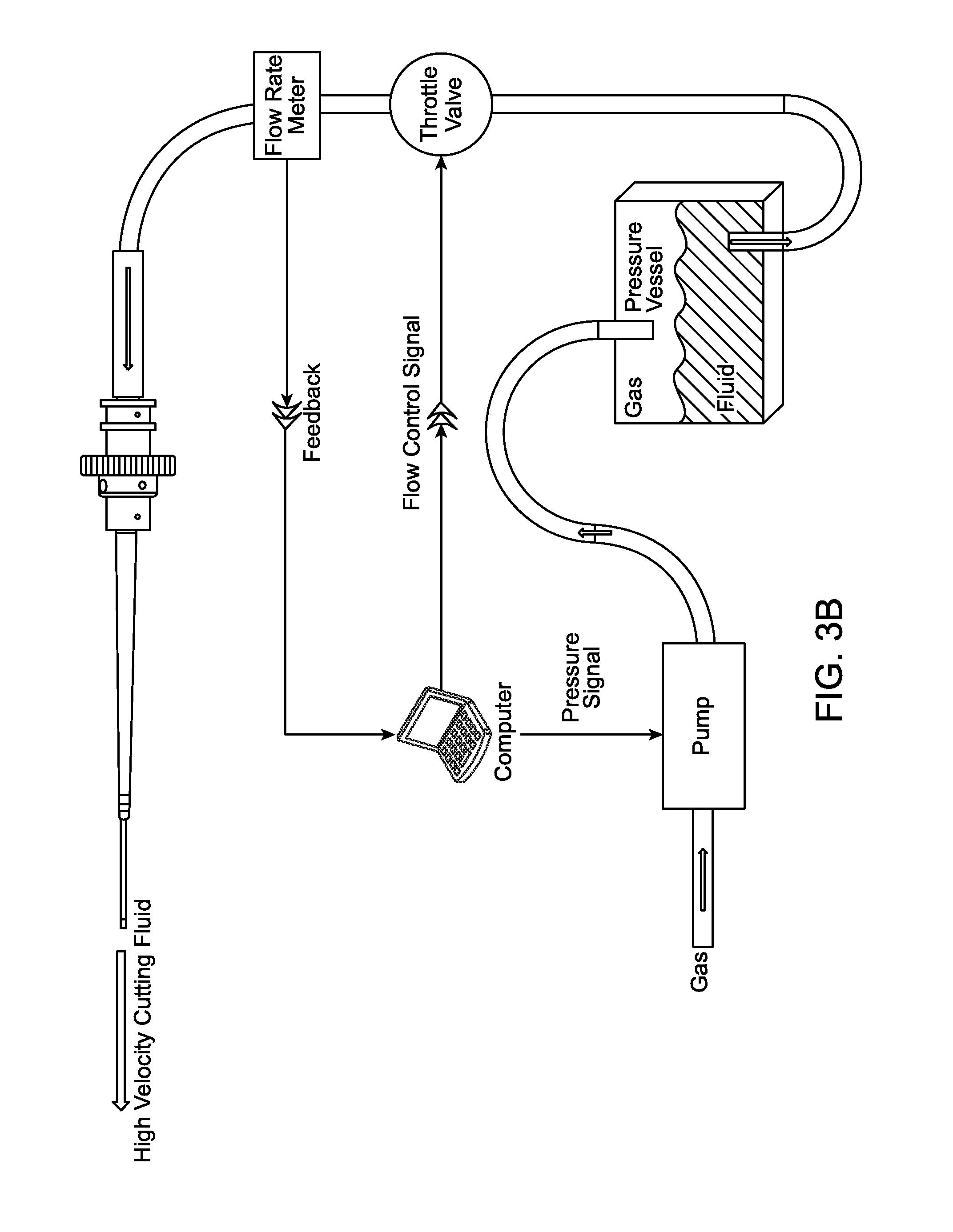
[0018] In another aspect of the present invention, the water jet apparatus utilizes a nozzle that has a jet cutting area and a dispersive area. In one embodiment, the water jet apparatus could be coupled to a system that incorporates a flow rate meter or pressure gauge, pressure vessel or reservoir, and pump. A feedback loop from the flow meter to the pump is controlled by a computer, central processing unit, microcontroller, or any custom application specific integrated circuit (ASIC). In another embodiment, a feedback loop exists at the aspiration pump that is controlled by a computer, central processing unit, microcontroller, or any custom application specific integrated circuit (ASIC). In yet another embodiment, a throttle valve helps to control the flow rate meter based on a feedback loop. All the previous embodiments are discussed in different versions of FIGS. 3A, B, C, and D.
[0019] These and other aspects and embodiments will be described in greater detail below, in reference to the attached drawing figures.
BRIEF DESCRIPTION OF THE DRAWINGS
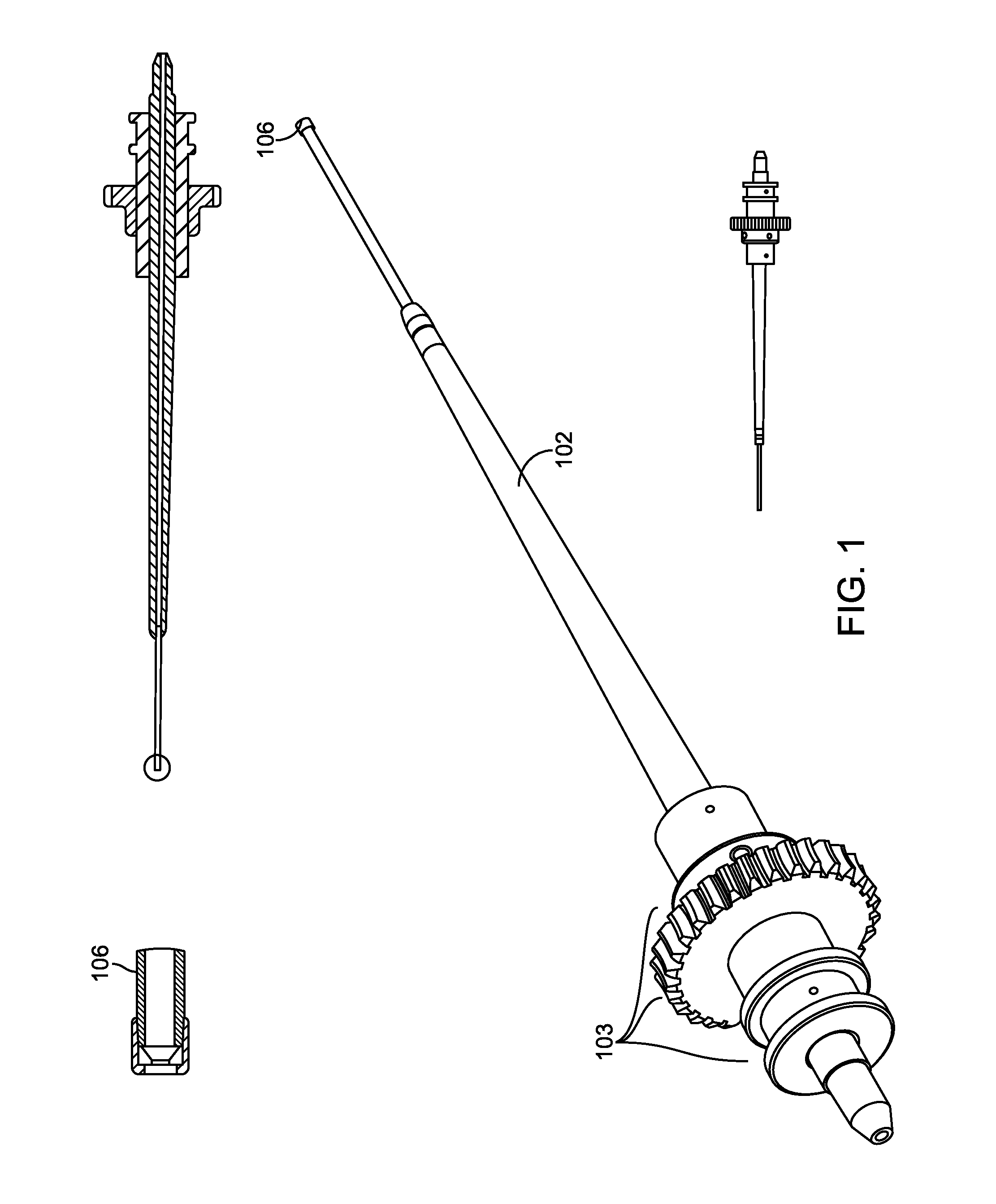
[0020] FIG. 1 is a perspective view of a water jet apparatus, according to one embodiment of the present invention;
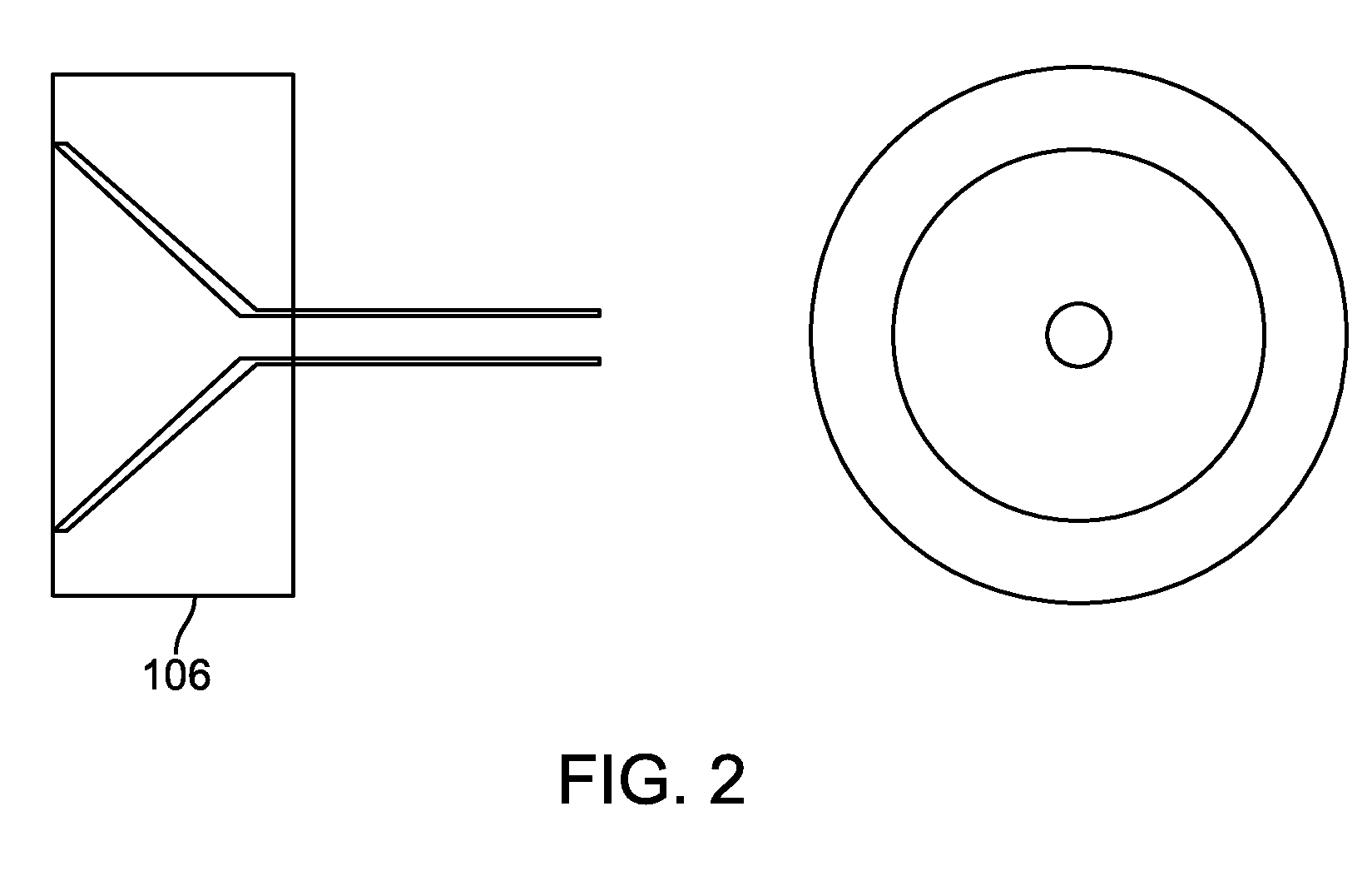
[0021] FIG. 2 is a side-view of a portion of a nozzle of the water jet apparatus depicted in FIG. 1;
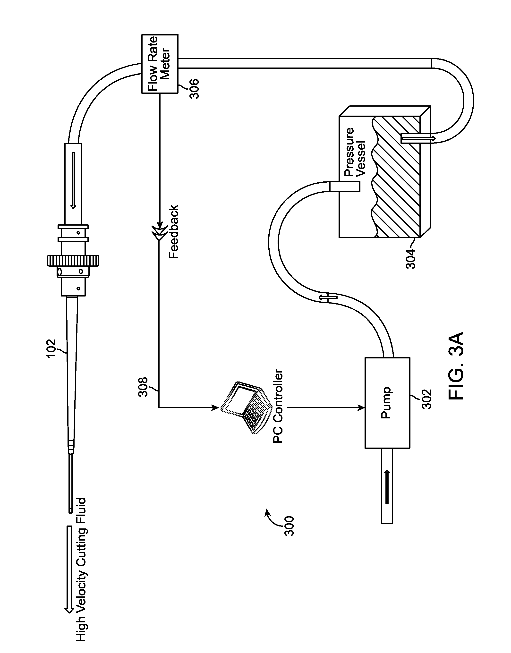
[0022] FIGS. 3A, 3B, 3C, 3D, and 3E are a block diagram of a water jet system, according to multiple embodiments of the present invention;
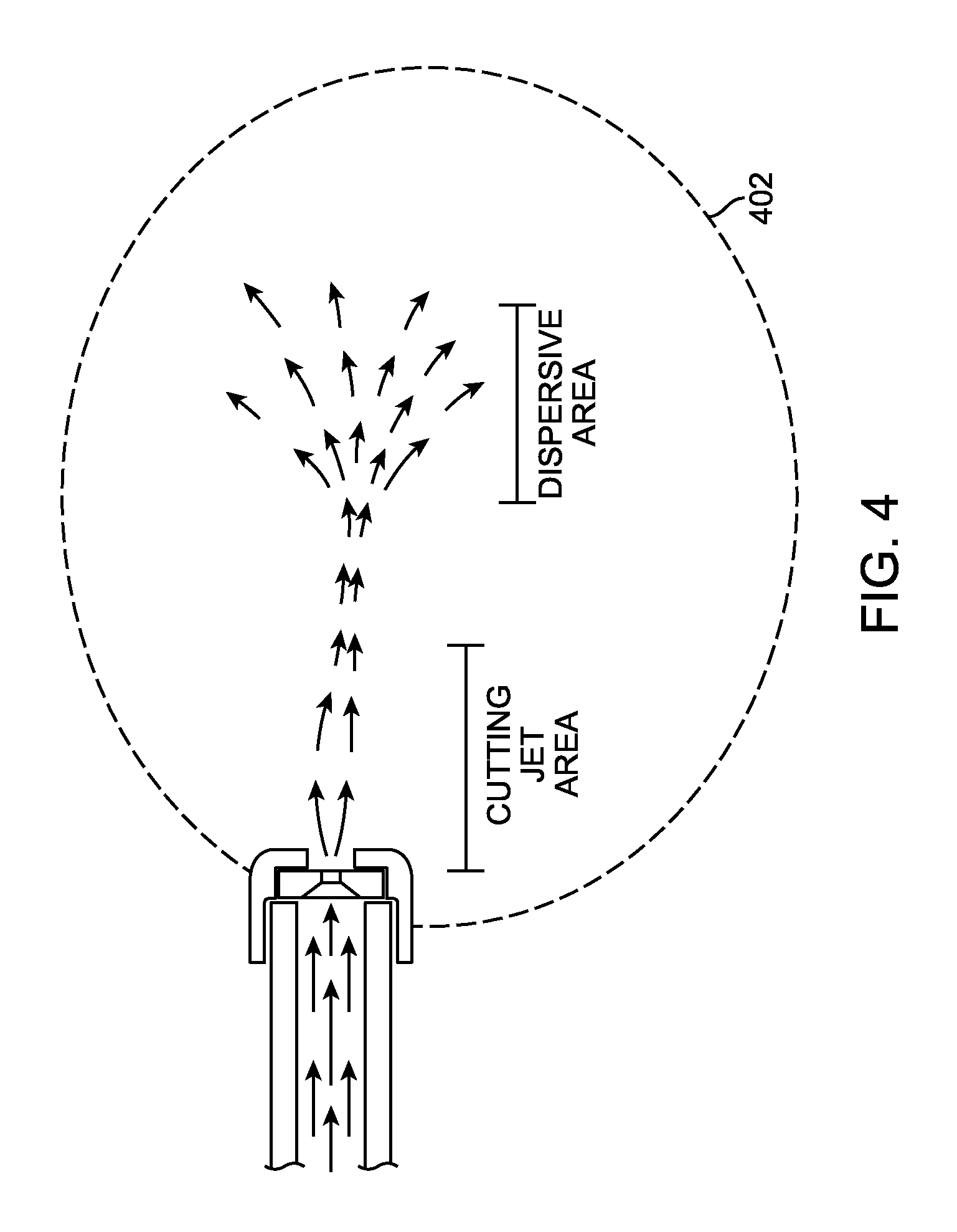
[0023] FIG. 4 is a cross section side view of an output of the nozzle with a cutting jet area and dispersive area depicted, according to another embodiment of the present invention;
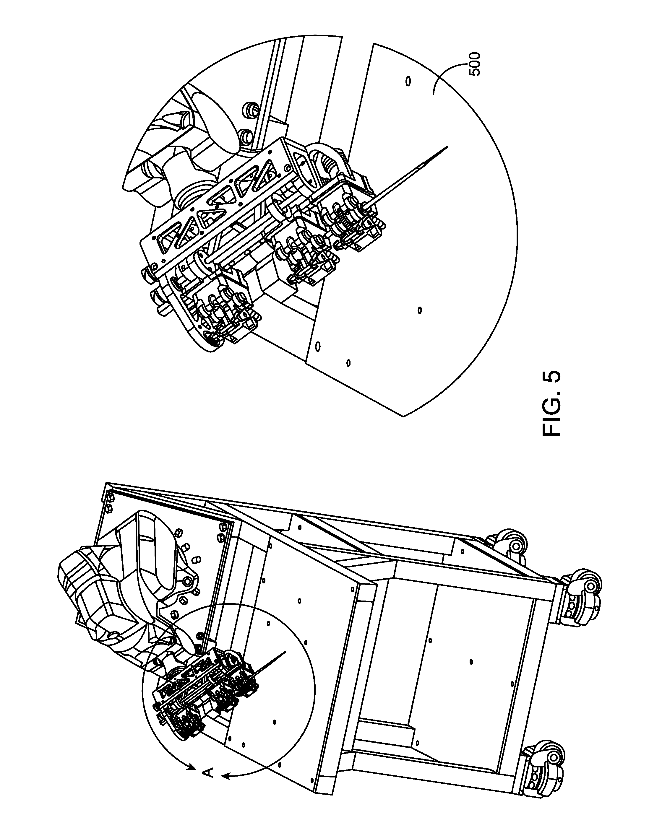
[0024] FIG. 5 is an instrument drive mechanism to couple the water jet to a robotic system, according to another embodiment of the present invention;
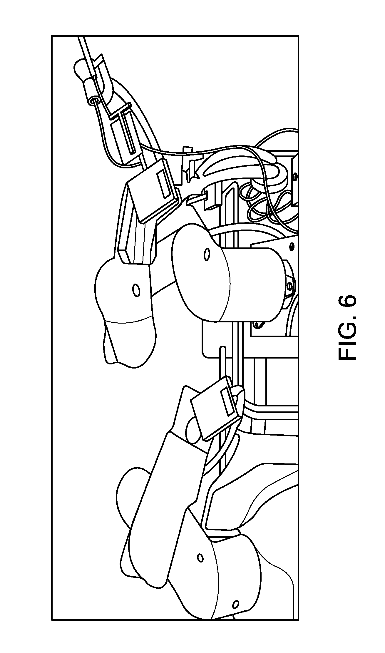
[0025] FIG. 6 is a robotic system to control the water jet apparatus or water jet system, according to another embodiment of the present invention;
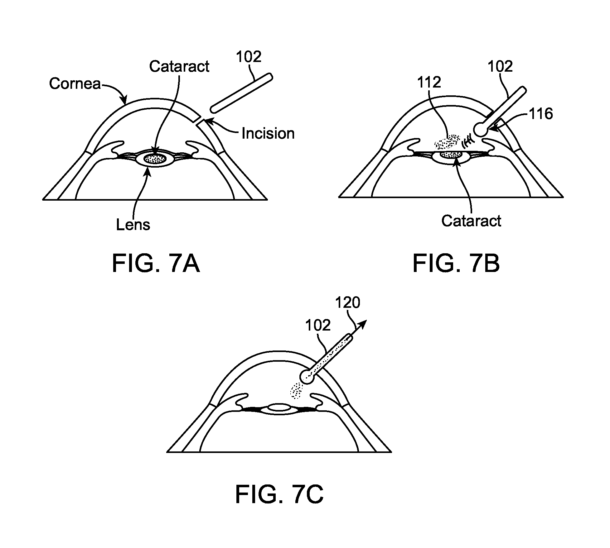
[0026] FIGS. 7A-7G are side, cross-sectional views of a portion of an eye, illustrating a method for using the water jet apparatus to perform cataract surgery, according to one embodiment of the present invention;
[0027] FIG. 8 is a common modern cataract extraction workflow; and
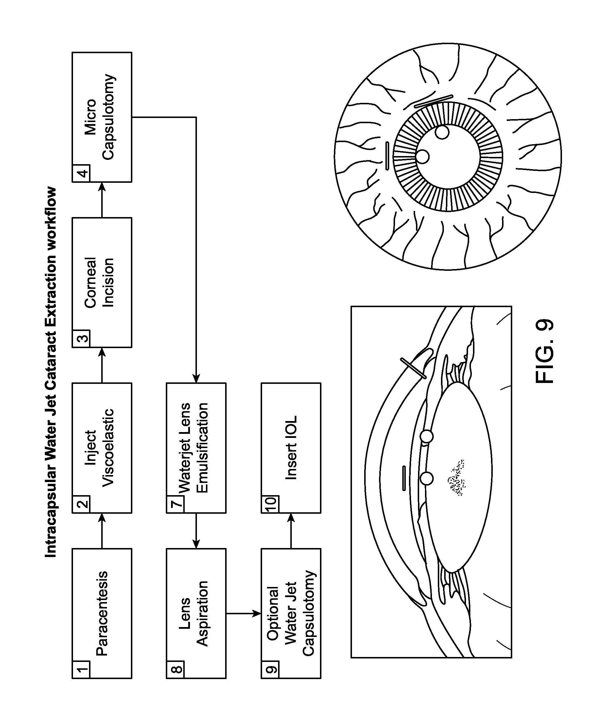
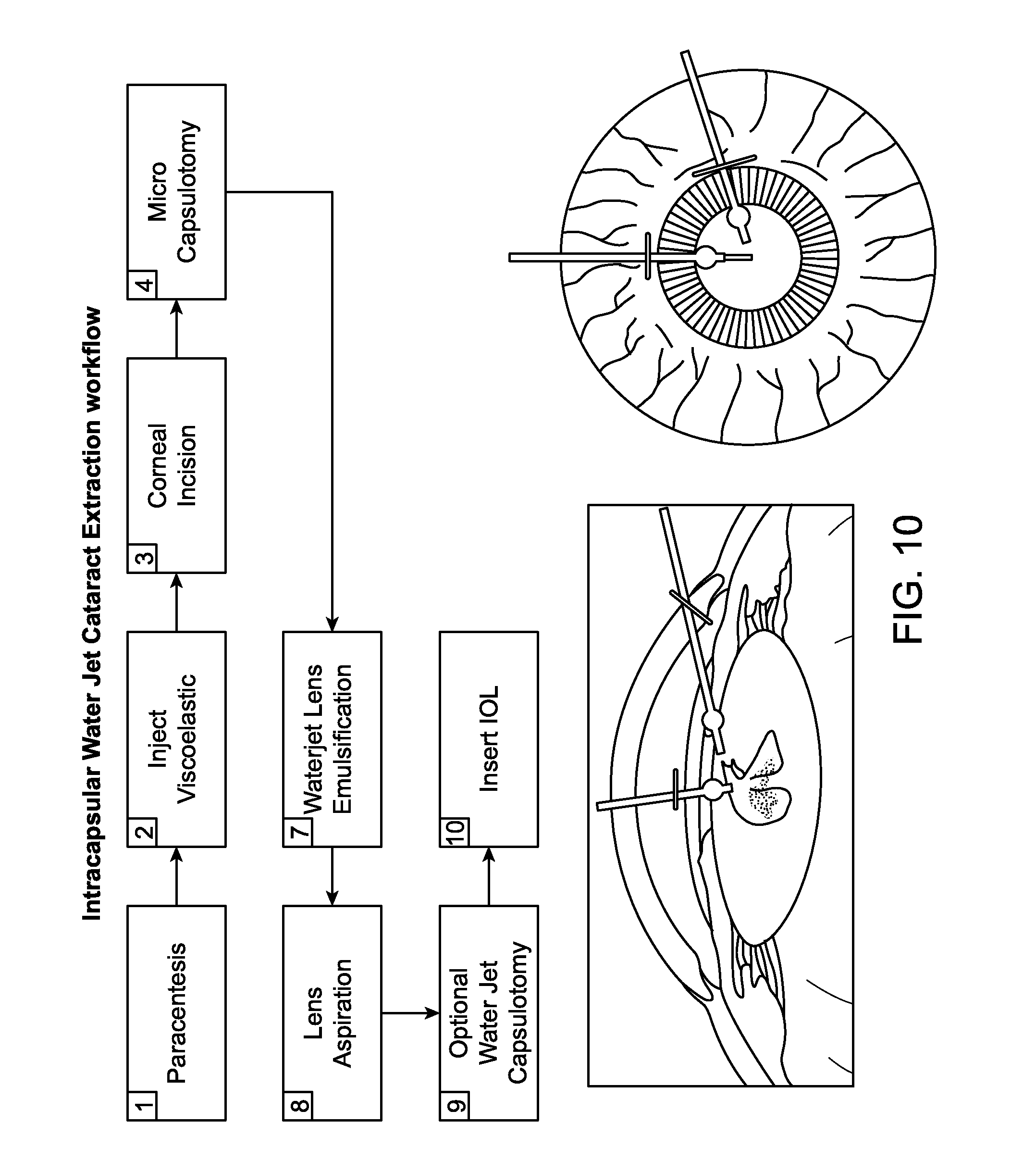
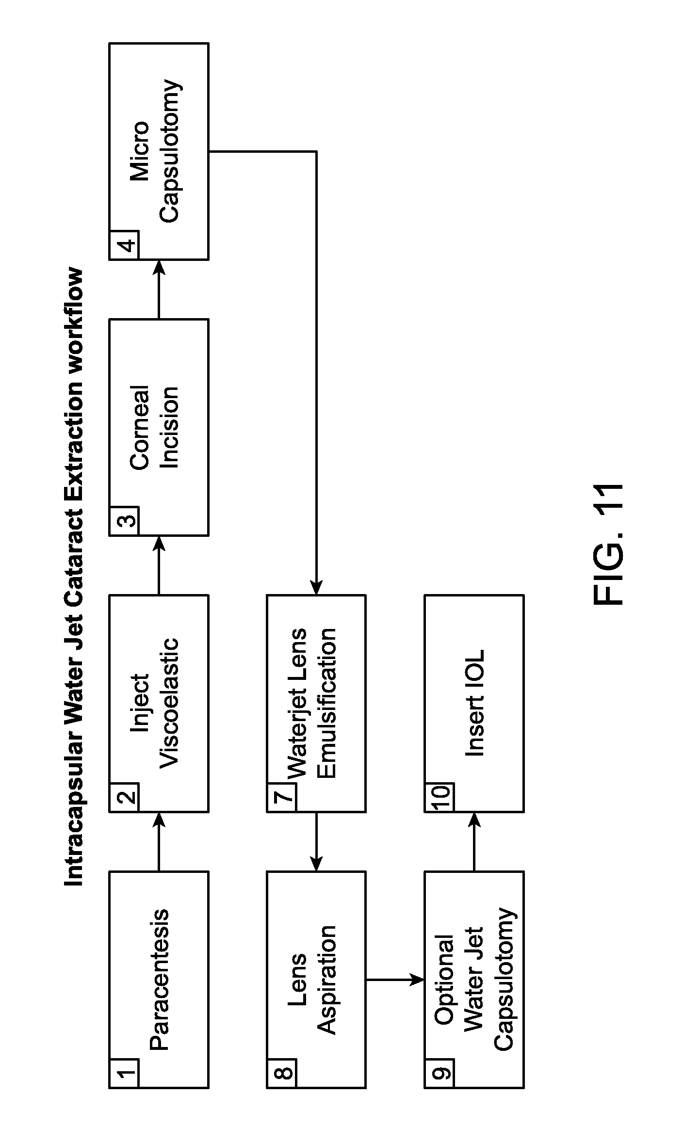
[0028] FIGS. 9-11 depict a method for a workflow based at least in part on utilizing the previous examples of a water jet apparatus or water jet system in manual or robotic system control, according to one embodiment of the present invention.
DETAILED DESCRIPTION OF THE PREFERRED EMBODIMENT
[0029] Although certain preferred embodiments and examples are disclosed below, inventive subject matter extends beyond the specifically disclosed embodiments to other alternative embodiments and/or uses, and to modifications and equivalents thereof. Thus, the scope of the claims appended hereto is not limited by any of the particular embodiments described below. For example, in any method or process disclosed herein, the acts or operations of the method or process may be performed in any suitable sequence and are not necessarily limited to any particular disclosed sequence. Various operations may be described as multiple discrete operations in turn, in a manner that may be helpful in understanding certain embodiments; however, the order of description should not be construed to imply that these operations are order dependent. Additionally, the structures, systems, and/or devices described herein may be embodied as integrated components or as separate components.
[0030] For purposes of comparing various embodiments, certain aspects and advantages of these embodiments are described. Not necessarily all such aspects or advantages are achieved by any particular embodiment. Thus, for example, various embodiments may be carried out in a manner that achieves or optimizes one advantage or group of advantages as taught herein without necessarily achieving other aspects or advantages as may also be taught or suggested herein.
[0031] The embodiments described herein are directed to method, apparatus, and system for performing surgery for various applications including eye, micro-surgery, and/or other emulsification applications. Specifically, in one embodiment, a water jet apparatus may be used for manually performing eye surgery such as, cataract, or perform micro-surgery (remove cartilage), or any emulsification technique. In the case of a cataract in an eye, a water jet apparatus or system may be used to break apart a cataract into multiple, smaller pieces, which may then be suctioned from the eye using the probe or other suction means. Although the method and device are typically described below in the context of treating cataracts, in various alternative embodiments, other eye conditions may be treated.
[0032] In other embodiments, a system with robotic control of the water jet apparatus may be used. In these embodiments, the water jet apparatus is coupled to a robotic arm via an instrument drive mechanism, depicted in connection with FIG. 5. It may be advantageous to incorporate any of the water jet apparatus or water jet system described herein into a robotic surgery/delivery system, such as, the system depicted in FIG. 6. For example, any of the water jet apparatus or water jet systems may be incorporated into the da Vinci.RTM. Surgical System, provided by Intuitive Surgical, Inc., or the Magellan.TM. Robotic System, provided by Hansen Medical, Inc. the RiO, provided by Mako Surgical or Carnegie Mellon's Micron, or John Hopkins University's Steady Hand. Robotic surgical systems such as (but not limited to) these examples may register the water jet apparatus to the target anatomy. Such capability enables both precise and safe movement water jet apparatus such that, when enabled, the fluid is focused in the desired jet cutting area and rapidly dispersed outside of that in order to treat the target tissue and spares injury to surrounding tissue. A number of robotic surgery systems are presently known, and others may be developed specifically for use with the water jet probes and methods described herein.
[0033] In other embodiments, methods and workflows for cataract extraction are discussed to facilitate the use of the previous apparatus and system embodiments. For example, the workflows depicted are efficient and replace typical steps in a common modern cataract extraction flow. For example, the common Hydro dissection, Nuclear fracture, and emsulfication steps are replaced with a single water jet emsulfication step. The improved workflows are depicted in connection with FIGS. 9-11.
[0034] In another aspect of the present invention, a method of utilizing the water jet apparatus treating a cataract in an eye may involve controlling a cutting jet area of the water jet based at least in part on a flow rate meter utilizing a feedback loop to a pump, as depicted in connection with FIG. 3.
[0035] In another aspect of the present invention, the water jet apparatus utilizes a nozzle that generates a jet cutting area and a dispersive area when pressurized water is passed through it into a fluid filled environment, a preferred embodiment uses saline. In one embodiment, the water jet apparatus could be coupled to a system that incorporates a flow rate meter, pressure vessel, and pump. A feedback loop from the flow meter to the pump is controlled by a computer or central processing unit, as depicted in connection with FIG. 3A.
[0036] Referring to FIGS. 1 and 2, one embodiment of a water jet apparatus 102 includes a tip with a nozzle 106 at a distal end and a instrument drive coupling mechanism 103 at a proximal end. The nozzle 106 is depicted in further detail in FIG. 2. In one embodiment, the instrument drive coupling mechanism 103 facilitates coupling to a instrument drive mechanism as depicted in connection with FIG. 5. For this embodiment, the apparatus may be controlled by a robotic system as depicted in connection with FIG. 6 or the previous embodiments depicted in connection with da Vinci.RTM. Surgical System, provided by Intuitive Surgical, Inc., or the Magellan.TM. Robotic System, provided by Hansen Medical, Inc., or Carnegie Mellon's Micron, or John Hopkins University's Steady Hand.
[0037] However, in another embodiment, the water jet apparatus 102 would not have a instrument drive coupling mechanism 103 and would be used in a manual and may have a different configuration at the proximal end.
[0038] In one embodiment, the water jet apparatus would consist of the probe 102. In another embodiment, the water jet apparatus could be configured to include or support the other block diagrams depicted in connection with FIGS. 3A, B, C, and D.
[0039] Referring to FIG. 2, a side-view a portion of a nozzle 106 of the water jet apparatus is depicted. In one embodiment, the nozzle 106 is a sapphire orifice manufactured by Swiss Jewel Company. In this embodiment, the nozzle 106 may have a plurality of different diameter measurements, thickness, angle, and Vee depth as depicted in the table in connection with FIG. 2. However, the claimed subject matter is not limited to neither the different measurements depicted nor configurations implied by the illustration. For instance one skilled in the art appreciates utilizing different measurements or configurations as needed for the particular application or other factors, such as, jet cutting area, dispersive area, pressure levels, exiting location or nozzle orientation.
[0040] However, the claimed subject matter is not limited to a sapphire orifice nozzle. One skilled in the art appreciates utilizing not only different nozzle configurations, but also different nozzle material, such as, but not limited to, diamond or stainless steel.
[0041] Referring to FIG. 3A, a block diagram of a water jet system 300 is depicted. As discussed earlier, the water jet apparatus 102 of FIG. 1 may incorporate or be coupled to block diagrams depicted in connection with FIGS. 3A, B, C, and D, such as, a pump, pressure vessel, throttle valve, aspiration pump, and flow rate meter.
[0042] In one embodiment for a robotic control system, the water jet apparatus 102 is controlled by a robotic system, because the water jet apparatus is coupled to an instrument drive mechanism. For this embodiment, the other blocks depicted, such as, flow rate meter, computer, feedback loop, pump, and pressure vessel, are coupled to the robotic arm while residing near the robotic arm.
[0043] In another embodiment, the water jet apparatus 102 includes a pressure vessel, and is controlled by a robotic system, because the water jet apparatus is coupled to an instrument drive mechanism. For this embodiment, the other blocks depicted, such as, flow rate meter, personal computer, feedback loop, and pump are coupled to the robotic arm while residing near the robotic arm.
[0044] In yet another embodiment, the water jet apparatus 102 is manually controlled and may be coupled to the other block diagrams via an interface.
[0045] In this water jet system 300, the fluid enters a pump 302 and is forwarded to a pressure vessel 304 via a tube. An output of the pressure vessel is forwarded to the flow rate meter 306. In one embodiment, an output of the flow rate meter is controlled by a feedback loop through a computer and a pump. The feedback loop facilitates the output of the flow rate meter based on a desired jet cutting area of an output of the nozzle 106 from the water jet apparatus.
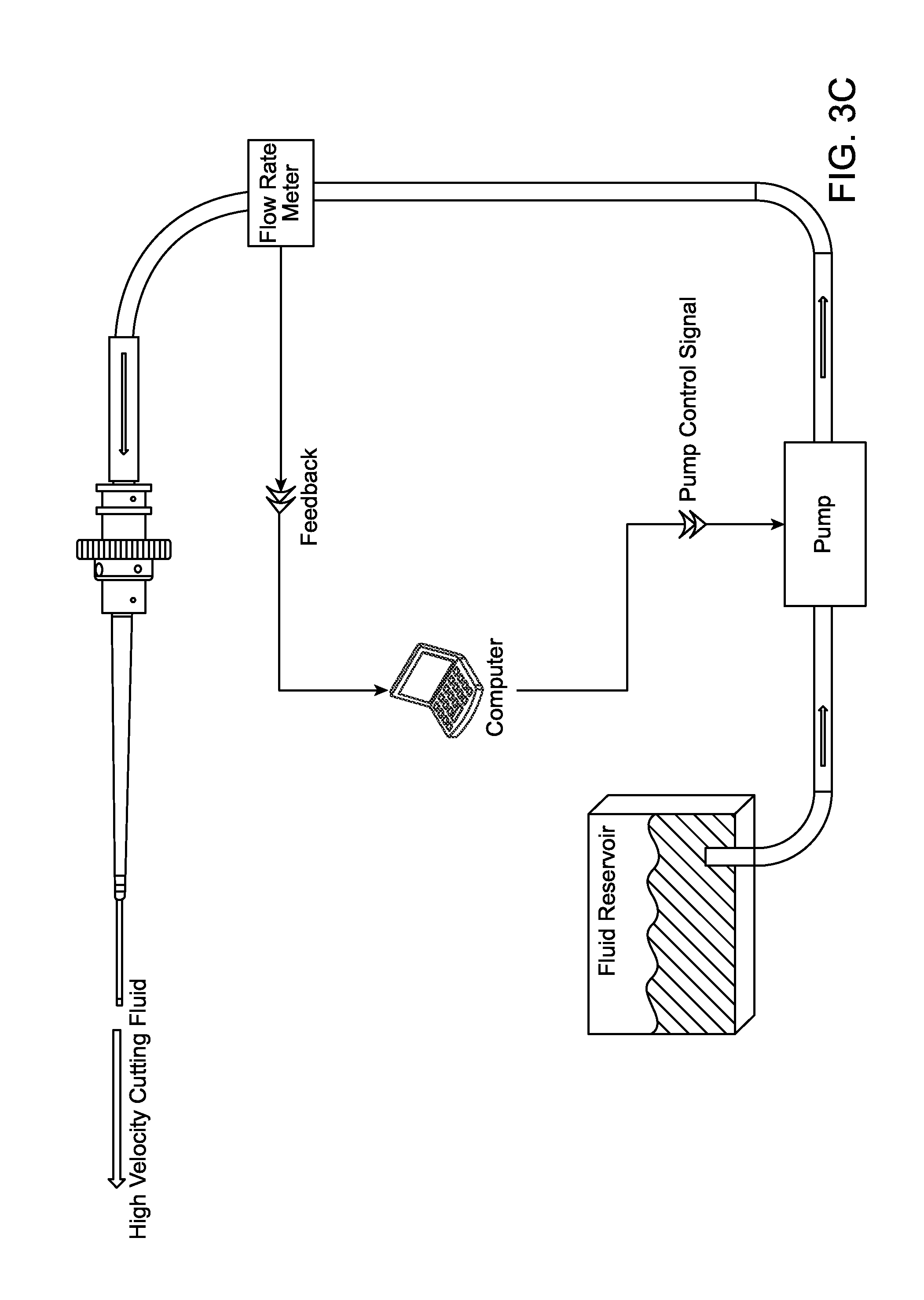
[0046] In alternative embodiments, FIG. 3B depicts a throttle valve to help facilitate the flow rate based on a feedback loop. In this embodiment, the throttle valve receives the control signal from either a computer, central processing unit, microcontroller, ASIC, or other control circuitry. In yet another embodiment, FIG. 3C depicts a fluid reservoir coupled to the pump, wherein the feedback loop between the flow rate meter and pump is controlled by a computer, central processing unit, microcontroller, ASIC, or other control circuitry.
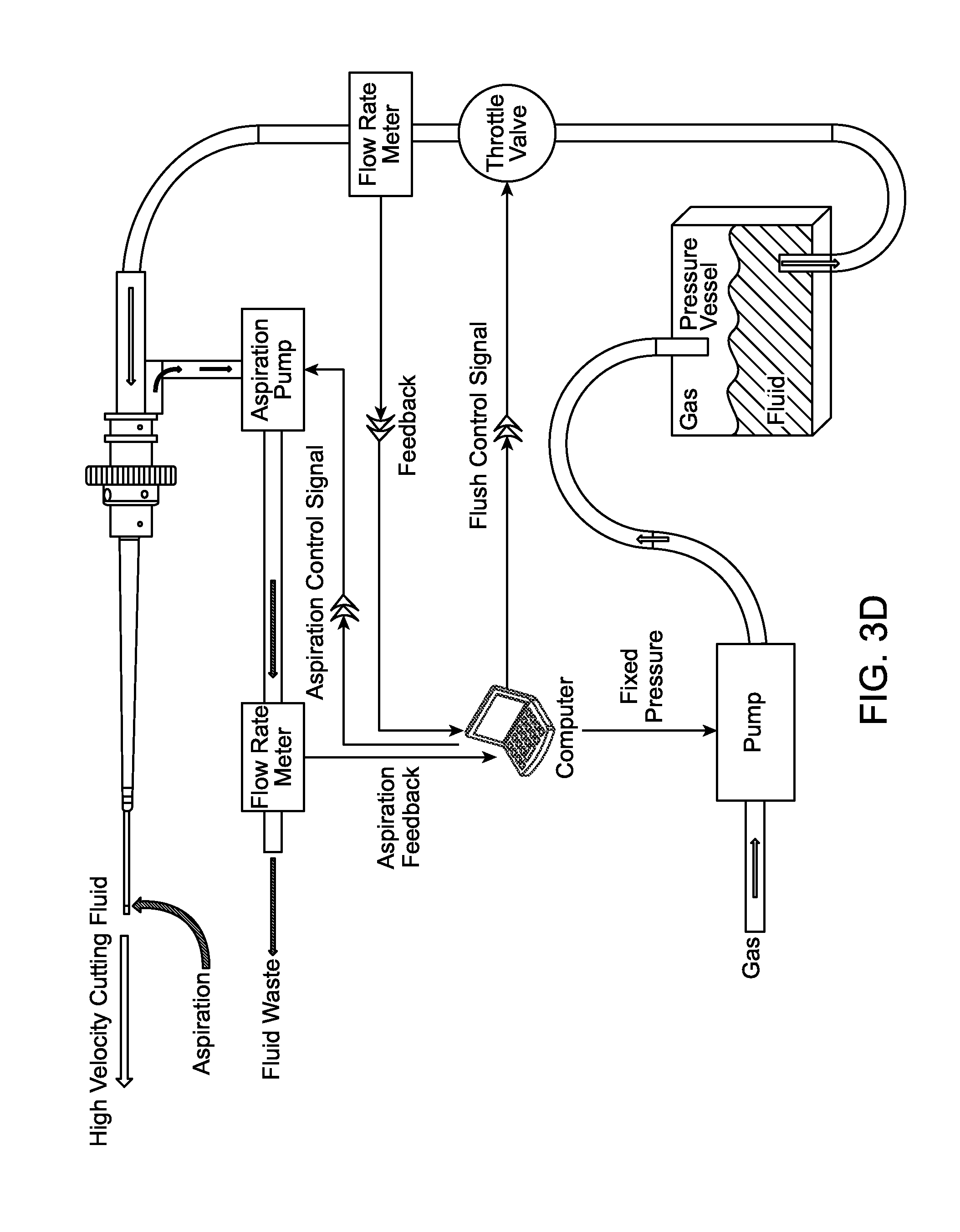
[0047] In yet another embodiment, FIG. 3D depicts an aspiration pump that controls removal of material from the operative site. It also has a feedback loop with a flow rate meter that is controlled by a computer, central processing unit, microcontroller, ASIC, or other control circuitry. The aspiration pump may be controlled by the Aspiration flow rate meter feedback signal and or the water jet flow rate meter feedback signal to maintain a desired absolute aspiration flow, or to track the water jet flow in order to maintain the material volume in an enclosed operative space like the interior of the eye. Similarly in this configuration the Water Jet flow may be moderated or interrupted automatically, using the throttle valve or pump control, based on the measured aspiration flow. This may be done in the event that the aspiration path is unable to match the desired flow rate due to blockage, pinched tube, or other mechanical failure.
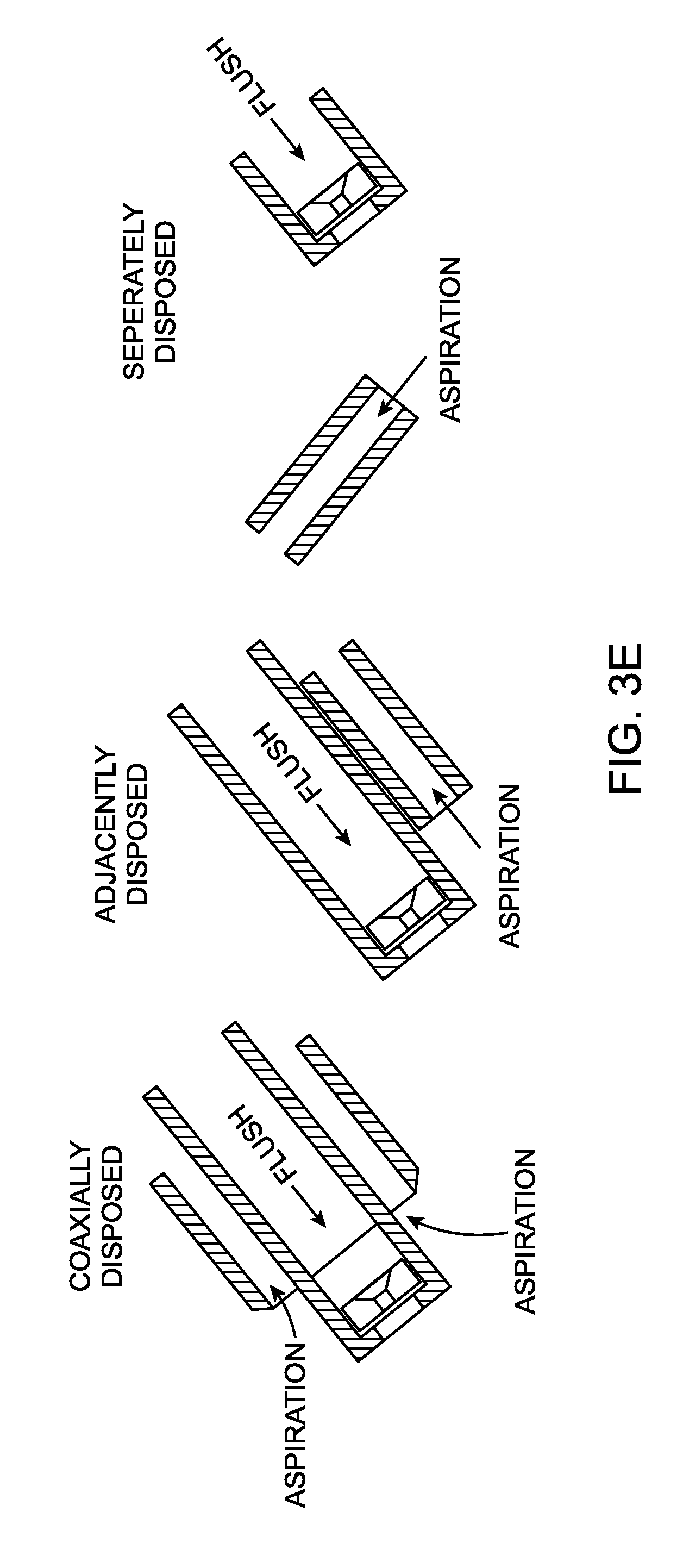
[0048] Referring to FIG. 3E, multiple embodiments of water jet system configurations are depicted. The configuration on the left depicts a coaxially disposed configuration of a water jet fluid flush with an aspiration on either side. The configuration in the center depicts an adjacently disposed water jet fluid flush and aspiration in a separate tube. In the embodiment on the far right, the water jet fluid flush and aspiration are separately disposed.
[0049] Referring to FIG. 4, a fluid output of the nozzle 106 is depicted as first a focused cutting jet area and eventually a dispersive area. In one embodiment, the cutting jet area and dispersive area are in a fluid medium 402, such as, a saline solution. As mentioned in connection with FIGS. 3A, B, C, and D, the feedback loops control the flow of fluid to the water jet apparatus 102. For example, if the jet cutting area needs to be increased, the flow rate meter could request an increase in pressure from the pump. Alternatively, if the jet cutting area needs to be decreased, the flow rate meter could request an decrease in pressure from the pump.
[0050] Referring to FIG. 5, an instrument drive mechanism to couple the water jet to a robotic system is depicted. In one embodiment, the instrument drive coupling mechanism 103 of FIG. 1 is used to facilitate coupling to the instrument drive mechanism depicted in FIG. 5. For this embodiment, the apparatus may be controlled by a robotic system as depicted in connection with FIG. 6 or the previous embodiments depicted in connection with da Vinci.RTM. Surgical System, provided by Intuitive Surgical, Inc., or the Magellan.TM. Robotic System, provided by Hansen Medical, Inc., or Carnegie Mellon's Micron, or John Hopkins University's Steady Hand.
[0051] However, the instrument drive mechanism is not limited to this embodiment. One skilled in the art appreciates modifications to facilitate coupling to different robotic arm configurations.
[0052] FIG. 6 is a robotic system to control the water jet apparatus or water jet system. As discussed earlier, the instrument drive mechanism described in FIG. 5 may be used to couple the water jet apparatus or system to facilitate control by this robotic system configuration.
[0053] In this embodiment for a robotic control system, two instrument drivers each of which contains an instrument interface that drives a medical instrument is depicted. However, the claimed subject matter is not limited to this particular robotic system and could support any robotic control system with one or more interfaces and one or more instrument drivers. As previously mentioned, various robotic systems facilitate control of the water jet apparatus within the eye. For example, the robotic systems could utilize known localization techniques, such as, 3D imaging, MRI, CT, Ultrasound, Intra operative (OCT), and the like.
[0054] Turning now to FIGS. 7A-7G, one embodiment of a method for treating a cataract is illustrated. For convenience, only a distal portion of the probe 102 is illustrated in these figures. Also, in various alternative embodiments of the method, the water jet 102 may either manual or coupled with a robotic surgery system. Thus, the present description may be applied to any delivery method, whether robotic or not. Any suitable imaging system may be incorporated as well, sometimes as part of the robotic system. Three dimensional imaging is but one example.
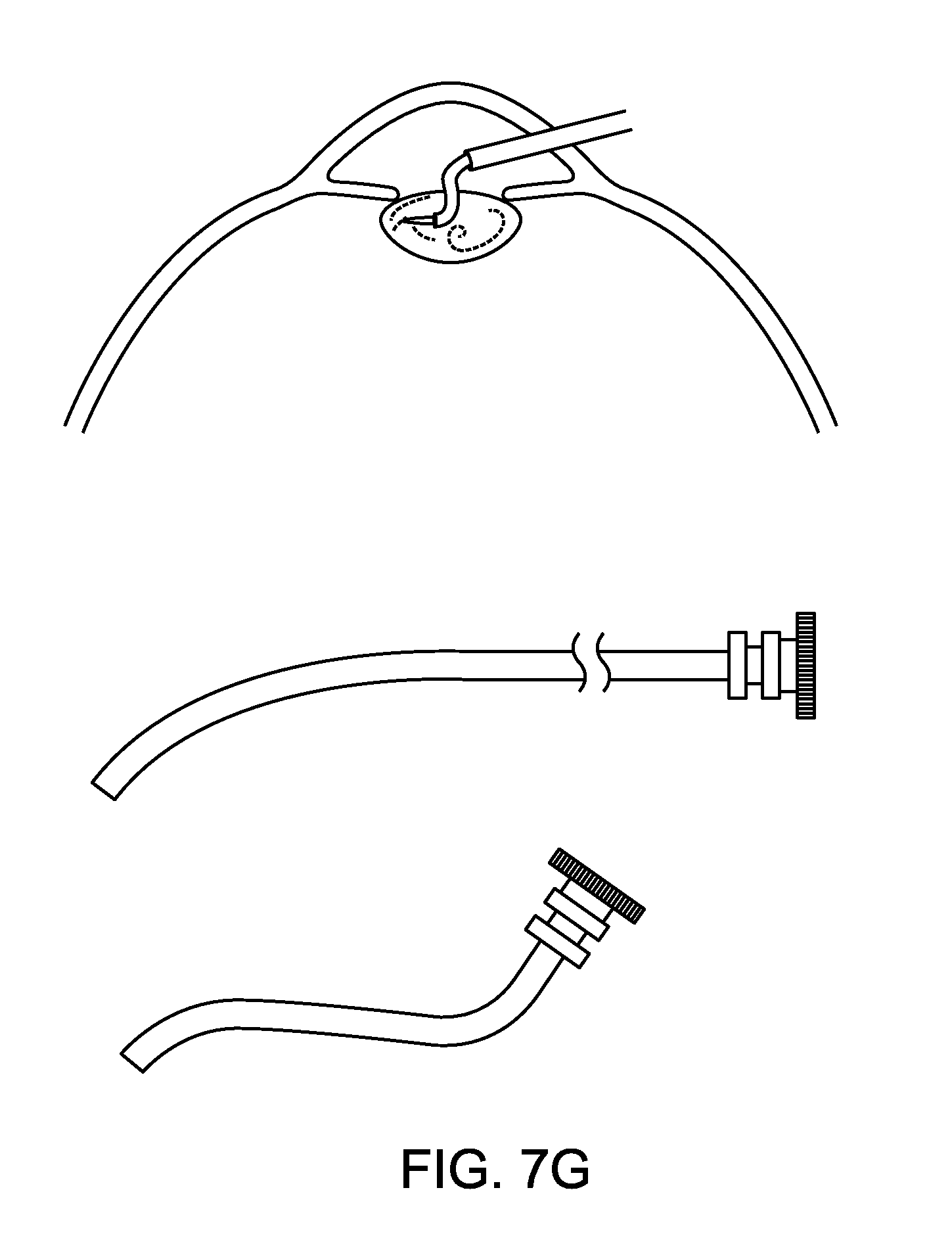
[0055] In FIG. 7A, a portion of an eye is shown in cross-section, including a cornea, lens and cataract, with an incision formed in the cornea. The water jet 102 (as described above or some alternative embodiment) may be inserted through the incision, as shown in FIG. 7B. Once the cataract is fully broken up or emulsified, as shown in FIG. 7C, the pieces of cataract may be aspirated. Alternatively, a separate aspiration device may be used. Once the cataract is removed, an intraocular lens (IOL) implant may be implanted, typically through the same incision.
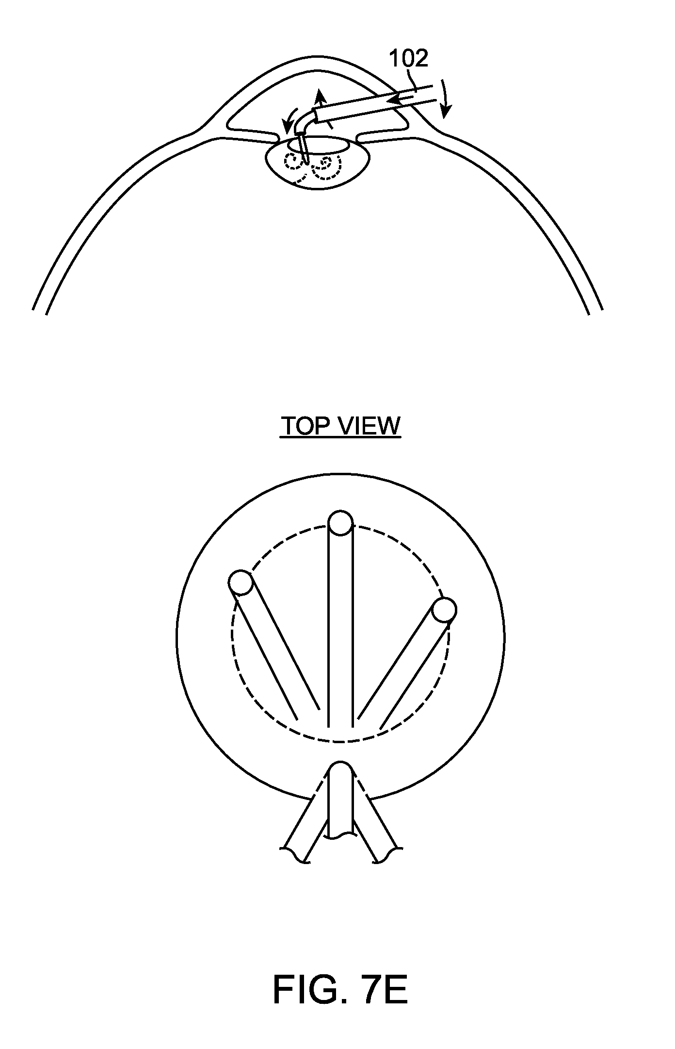
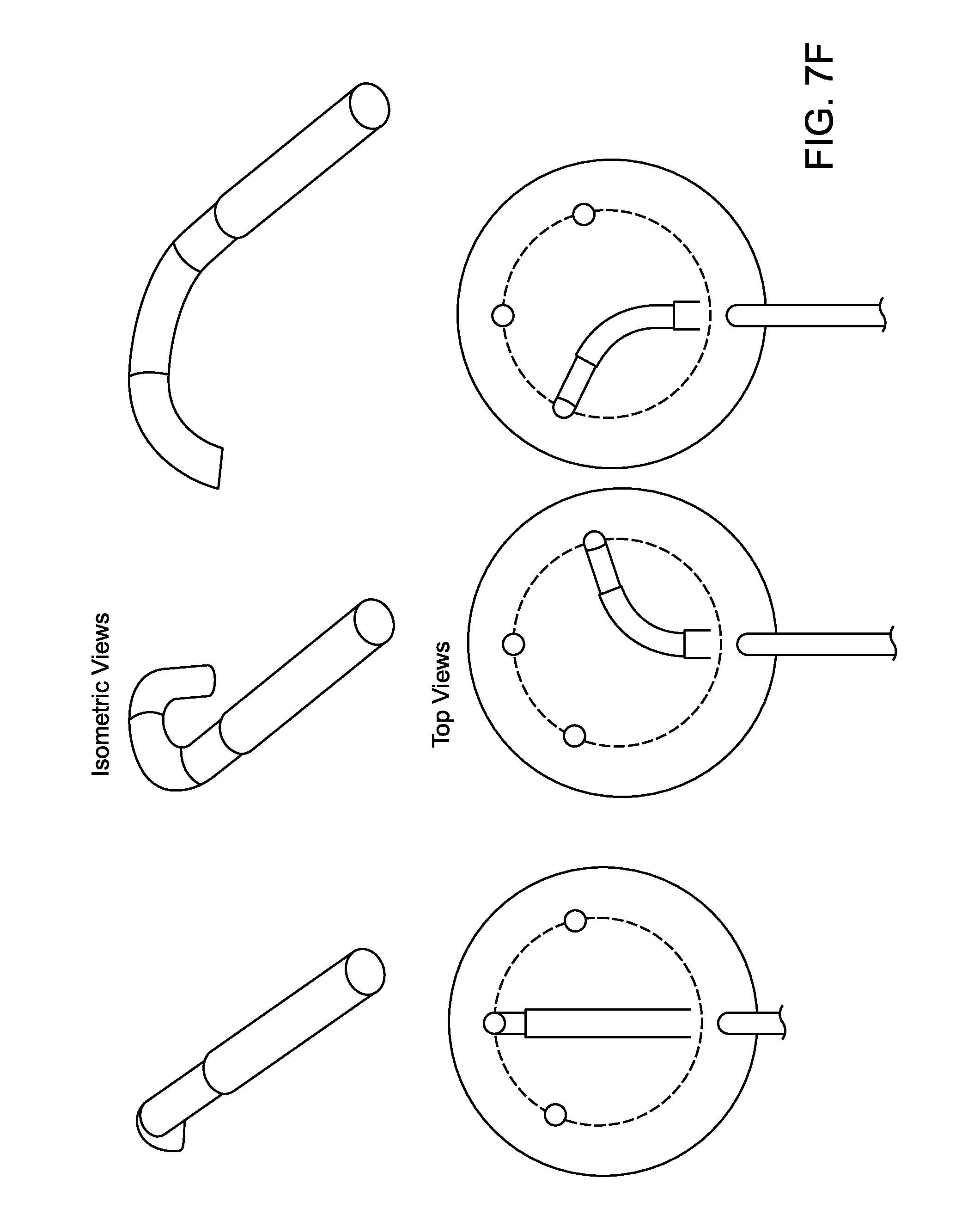
[0056] Different instrument configurations for the water jet are depicted in FIG. 7D (bent tube 108 with a nozzle 106), FIG. 7E depicts a pattern of cuts for a circle configuration, as required for a capsulotomy, with a yaw rotation movement of the water jet. The depiction of a circle is for illustrative purposes only, one schooled in the art will realize that other shapes or patterns can be generated manually or under robotic control as required by the surgical procedure. FIG. 7F depicts an isometric view and a top view of a plurality of shaped tubes, axially translatable to vary articulation angle, and configured to reduce proximal motion of the instrument, while enabling complex distal tip motion. FIG. 7G depicts multiple potentially retractable tip configurations for the water jet apparatus.
[0057] In alternative embodiments, any other suitable type of articulation mechanism may be used to articulate the water jet apparatus. Examples include, but are not limited to, concentric shaped tubes, flexures, pivot joints, cam mechanisms, pull wire enabled bending, slotted tubes and the like.
[0058] FIGS. 9-11 depict a method for a workflow based at least in part on utilizing the previous examples of a water jet apparatus or water jet system in manual or robotic system control, according to one embodiment of the present invention. The figures include descriptive text to facilitate understanding of the different workflow as compared to FIG. 8.
[0059] Elements or components shown with any embodiment herein are exemplary for the specific embodiment and may be used on or in combination with other embodiments disclosed herein. While the invention is susceptible to various modifications and alternative forms, specific examples thereof have been shown in the drawings and are herein described in detail. The invention is not limited, however, to the particular forms or methods disclosed, but to the contrary, covers all modifications, equivalents and alternatives thereof.
* * * * *
D00000
D00001
D00002
D00003
D00004
D00005
D00006
D00007
D00008
D00009
D00010
D00011
D00012

D00013
D00014
D00015
D00016
D00017
D00018
D00019
XML
uspto.report is an independent third-party trademark research tool that is not affiliated, endorsed, or sponsored by the United States Patent and Trademark Office (USPTO) or any other governmental organization. The information provided by uspto.report is based on publicly available data at the time of writing and is intended for informational purposes only.
While we strive to provide accurate and up-to-date information, we do not guarantee the accuracy, completeness, reliability, or suitability of the information displayed on this site. The use of this site is at your own risk. Any reliance you place on such information is therefore strictly at your own risk.
All official trademark data, including owner information, should be verified by visiting the official USPTO website at www.uspto.gov. This site is not intended to replace professional legal advice and should not be used as a substitute for consulting with a legal professional who is knowledgeable about trademark law.