Surgical buttress retention systems for surgical stapling apparatus
Mozdzierz December 1, 2
U.S. patent number 10,849,625 [Application Number 16/037,007] was granted by the patent office on 2020-12-01 for surgical buttress retention systems for surgical stapling apparatus. This patent grant is currently assigned to COVIDIEN LP. The grantee listed for this patent is Covidien LP. Invention is credited to Patrick Mozdzierz.


| United States Patent | 10,849,625 |
| Mozdzierz | December 1, 2020 |
Surgical buttress retention systems for surgical stapling apparatus
Abstract
A surgical stapling apparatus includes a jaw assembly including an anvil assembly and a staple cartridge assembly, at least one which includes a surgical buttress retention system, and a surgical buttress releasably secured to a tissue facing surface of the anvil assembly or the staple cartridge assembly via the surgical buttress retention system. The surgical buttress retention system includes proximal guide slots defined in opposed sides of the anvil assembly or the staple cartridge assembly that have a generally U-shaped configuration that are mirror images of each other, a plug coupled to a distal portion of the anvil assembly or the staple cartridge assembly, and a retention member including a central portion extending across a proximal portion of the surgical buttress, second portions positioned within the proximal guide slots, third portions extending across a distal portion of the surgical buttress, and end portions coupled to the plug.
| Inventors: | Mozdzierz; Patrick (Glastonbury, CT) | ||||||||||
|---|---|---|---|---|---|---|---|---|---|---|---|
| Applicant: |
|
||||||||||
| Assignee: | COVIDIEN LP (Mansfield,
MA) |
||||||||||
| Family ID: | 1000005212502 | ||||||||||
| Appl. No.: | 16/037,007 | ||||||||||
| Filed: | July 17, 2018 |
Prior Publication Data
| Document Identifier | Publication Date | |
|---|---|---|
| US 20190038285 A1 | Feb 7, 2019 | |
Related U.S. Patent Documents
| Application Number | Filing Date | Patent Number | Issue Date | ||
|---|---|---|---|---|---|
| 62541970 | Aug 7, 2017 | ||||
| Current U.S. Class: | 1/1 |
| Current CPC Class: | A61B 17/07207 (20130101); A61B 17/07292 (20130101); A61B 17/0682 (20130101); A61B 2017/00004 (20130101); A61B 2017/07271 (20130101); A61B 2017/07278 (20130101); A61B 2017/07285 (20130101); A61B 2017/0053 (20130101); A61B 2017/07257 (20130101); A61B 2017/00526 (20130101) |
| Current International Class: | A61B 17/072 (20060101); A61B 17/068 (20060101); A61B 17/00 (20060101) |
| Field of Search: | ;227/175.1-182.1 ;606/75,219,220 |
References Cited [Referenced By]
U.S. Patent Documents
| 3054406 | September 1962 | Usher |
| 3079606 | March 1963 | Bobrov et al. |
| 3124136 | March 1964 | Usher |
| 3364200 | January 1968 | Ashton et al. |
| 3490675 | January 1970 | Green et al. |
| 3499591 | March 1970 | Green |
| 3797494 | March 1974 | Zaffaroni |
| 3939068 | February 1976 | Wendt et al. |
| 3948666 | April 1976 | Kitanishi et al. |
| 4064062 | December 1977 | Yurko |
| 4166800 | September 1979 | Fong |
| 4282236 | August 1981 | Broom |
| 4347847 | September 1982 | Usher |
| 4354628 | October 1982 | Green |
| 4416698 | November 1983 | McCorsley, III |
| 4429695 | February 1984 | Green |
| 4452245 | June 1984 | Usher |
| 4605730 | August 1986 | Shalaby et al. |
| 4626253 | December 1986 | Broadnax, Jr. |
| 4655221 | April 1987 | Devereux |
| 4834090 | May 1989 | Moore |
| 4838884 | June 1989 | Dumican et al. |
| 4927640 | May 1990 | Dahlinder et al. |
| 4930674 | June 1990 | Barak |
| 5002551 | March 1991 | Linsky et al. |
| 5014899 | May 1991 | Presty et al. |
| 5040715 | August 1991 | Green et al. |
| 5057334 | October 1991 | Vail |
| 5065929 | November 1991 | Schulze et al. |
| 5112496 | May 1992 | Dhawan et al. |
| 5162430 | November 1992 | Rhee et al. |
| 5205459 | April 1993 | Brinkerhoff et al. |
| 5263629 | November 1993 | Trumbull et al. |
| 5281197 | January 1994 | Arias et al. |
| 5307976 | May 1994 | Olson et al. |
| 5312023 | May 1994 | Green et al. |
| 5314471 | May 1994 | Brauker et al. |
| 5318221 | June 1994 | Green et al. |
| 5324775 | June 1994 | Rhee et al. |
| 5326013 | July 1994 | Green et al. |
| 5332142 | July 1994 | Robinson et al. |
| 5344454 | September 1994 | Clarke et al. |
| 5392979 | February 1995 | Green et al. |
| 5397324 | March 1995 | Carroll et al. |
| 5405072 | April 1995 | Zlock et al. |
| 5410016 | April 1995 | Hubbell et al. |
| 5425745 | June 1995 | Green et al. |
| 5441193 | August 1995 | Gravener |
| 5441507 | August 1995 | Wilk |
| 5443198 | August 1995 | Viola et al. |
| 5468253 | November 1995 | Bezwada et al. |
| 5484913 | January 1996 | Stilwell et al. |
| 5503638 | April 1996 | Cooper et al. |
| 5514379 | May 1996 | Weissleder et al. |
| 5542594 | August 1996 | McKean et al. |
| 5543441 | August 1996 | Rhee et al. |
| 5549628 | August 1996 | Cooper et al. |
| 5550187 | August 1996 | Rhee et al. |
| 5575803 | November 1996 | Cooper et al. |
| 5645915 | July 1997 | Kranzler et al. |
| 5653756 | August 1997 | Clarke et al. |
| 5683809 | November 1997 | Freeman et al. |
| 5690675 | November 1997 | Sawyer et al. |
| 5702409 | December 1997 | Rayburn et al. |
| 5752965 | May 1998 | Francis et al. |
| 5752974 | May 1998 | Rhee et al. |
| 5762256 | June 1998 | Mastri et al. |
| 5766188 | June 1998 | Igaki |
| 5769892 | June 1998 | Kingwell |
| 5782396 | July 1998 | Mastri et al. |
| 5799857 | September 1998 | Robertson et al. |
| 5810855 | September 1998 | Rayburn et al. |
| 5814057 | September 1998 | Oi et al. |
| 5819350 | October 1998 | Wang |
| 5833695 | November 1998 | Yoon |
| 5843096 | December 1998 | Igaki et al. |
| 5871135 | February 1999 | Williamson, IV et al. |
| 5874500 | February 1999 | Rhee et al. |
| 5895412 | April 1999 | Tucker |
| 5895415 | April 1999 | Chow et al. |
| 5902312 | May 1999 | Frater |
| 5908427 | June 1999 | McKean et al. |
| 5915616 | June 1999 | Viola et al. |
| 5931847 | August 1999 | Bittner et al. |
| 5957363 | September 1999 | Heck |
| 5964394 | October 1999 | Robertson |
| 5964774 | October 1999 | McKean et al. |
| 5997895 | December 1999 | Narotam et al. |
| 6019791 | February 2000 | Wood |
| 6030392 | February 2000 | Dakov |
| 6032849 | March 2000 | Mastri et al. |
| 6045560 | April 2000 | McKean et al. |
| 6063097 | May 2000 | Oi et al. |
| 6080169 | June 2000 | Turtel |
| 6093557 | July 2000 | Pui et al. |
| 6099551 | August 2000 | Gabbay |
| 6142933 | November 2000 | Longo et al. |
| 6149667 | November 2000 | Hovland et al. |
| 6152943 | November 2000 | Sawhney |
| 6155265 | December 2000 | Hammerslag |
| 6156677 | December 2000 | Brown Reed et al. |
| 6165201 | December 2000 | Sawhney et al. |
| 6179862 | January 2001 | Sawhney |
| 6210439 | April 2001 | Firmin et al. |
| 6214020 | April 2001 | Mulhauser et al. |
| 6241139 | June 2001 | Milliman et al. |
| 6258107 | July 2001 | Balazs et al. |
| 6267772 | July 2001 | Mulhauser et al. |
| 6270530 | August 2001 | Eldridge et al. |
| 6273897 | August 2001 | Dalessandro et al. |
| 6280453 | August 2001 | Kugel et al. |
| 6299631 | October 2001 | Shalaby |
| 6309569 | October 2001 | Farrar et al. |
| 6312457 | November 2001 | DiMatteo et al. |
| 6312474 | November 2001 | Francis et al. |
| 6325810 | December 2001 | Hamilton et al. |
| 6330965 | December 2001 | Milliman et al. |
| 6399362 | June 2002 | Pui et al. |
| 6436030 | August 2002 | Rehil |
| 6454780 | September 2002 | Wallace |
| 6461368 | October 2002 | Fogarty et al. |
| 6500777 | December 2002 | Wiseman et al. |
| 6503257 | January 2003 | Grant et al. |
| 6514283 | February 2003 | DiMatteo et al. |
| 6514534 | February 2003 | Sawhney |
| 6517566 | February 2003 | Hovland et al. |
| 6551356 | April 2003 | Rousseau |
| 6566406 | May 2003 | Pathak et al. |
| 6568398 | May 2003 | Cohen |
| 6590095 | July 2003 | Schleicher et al. |
| 6592597 | July 2003 | Grant et al. |
| 6605294 | August 2003 | Sawhney |
| 6610006 | August 2003 | Amid et al. |
| 6627749 | September 2003 | Kumar |
| 6638285 | October 2003 | Gabbay |
| 6652594 | November 2003 | Francis et al. |
| 6656193 | December 2003 | Grant et al. |
| 6656200 | December 2003 | Li et al. |
| 6669735 | December 2003 | Pelissier |
| 6673093 | January 2004 | Sawhney |
| 6677258 | January 2004 | Carroll et al. |
| 6685714 | February 2004 | Rousseau |
| 6702828 | March 2004 | Whayne |
| 6703047 | March 2004 | Sawhney et al. |
| 6704210 | March 2004 | Myers |
| 6723114 | April 2004 | Shalaby |
| 6726706 | April 2004 | Dominguez |
| 6736823 | May 2004 | Darois et al. |
| 6736854 | May 2004 | Vadurro et al. |
| 6746458 | June 2004 | Cloud |
| 6746869 | June 2004 | Pui et al. |
| 6764720 | July 2004 | Pui et al. |
| 6773458 | August 2004 | Brauker et al. |
| 6818018 | November 2004 | Sawhney |
| 6843252 | January 2005 | Harrison et al. |
| 6896684 | May 2005 | Monassevitch et al. |
| 6927315 | August 2005 | Heinecke et al. |
| 6939358 | September 2005 | Palacios et al. |
| 6946196 | September 2005 | Foss |
| 6953139 | October 2005 | Milliman et al. |
| 6959851 | November 2005 | Heinrich |
| 7009034 | March 2006 | Pathak et al. |
| 7025772 | April 2006 | Gellman et al. |
| 7060087 | June 2006 | DiMatteo et al. |
| 7087065 | August 2006 | Ulmsten et al. |
| 7108701 | September 2006 | Evens et al. |
| 7128253 | October 2006 | Mastri et al. |
| 7128748 | October 2006 | Mooradian et al. |
| 7134438 | November 2006 | Makower et al. |
| 7141055 | November 2006 | Abrams et al. |
| 7147138 | December 2006 | Shelton, IV |
| 7160299 | January 2007 | Baily |
| 7179268 | February 2007 | Roy et al. |
| 7210810 | May 2007 | Iversen et al. |
| 7214727 | May 2007 | Kwon et al. |
| 7232449 | June 2007 | Sharkawy et al. |
| 7241300 | July 2007 | Sharkawy et al. |
| 7247338 | July 2007 | Pui et al. |
| 7279322 | October 2007 | Pui et al. |
| 7307031 | December 2007 | Carroll et al. |
| 7308998 | December 2007 | Mastri et al. |
| 7311720 | December 2007 | Mueller et al. |
| 7328829 | February 2008 | Arad et al. |
| 7334717 | February 2008 | Rethy et al. |
| 7347850 | March 2008 | Sawhney |
| 7377928 | May 2008 | Zubik et al. |
| 7434717 | October 2008 | Shelton, IV et al. |
| 7438209 | October 2008 | Hess et al. |
| 7464849 | December 2008 | Shelton, IV et al. |
| 7498063 | March 2009 | Pui et al. |
| 7547312 | June 2009 | Bauman et al. |
| 7559937 | July 2009 | de la Torre et al. |
| 7571845 | August 2009 | Viola |
| 7592418 | September 2009 | Pathak et al. |
| 7594921 | September 2009 | Browning |
| 7595392 | September 2009 | Kumar et al. |
| 7604151 | October 2009 | Hess et al. |
| 7611494 | November 2009 | Campbell et al. |
| 7635073 | December 2009 | Heinrich |
| 7645874 | January 2010 | Saferstein et al. |
| 7649089 | January 2010 | Kumar et al. |
| 7655288 | February 2010 | Bauman et al. |
| 7662409 | February 2010 | Masters |
| 7662801 | February 2010 | Kumar et al. |
| 7665646 | February 2010 | Prommersberger |
| 7666198 | February 2010 | Suyker et al. |
| 7669747 | March 2010 | Weisenburgh, II et al. |
| 7673782 | March 2010 | Hess et al. |
| 7708180 | May 2010 | Murray et al. |
| 7709631 | May 2010 | Harris et al. |
| 7717313 | May 2010 | Criscuolo et al. |
| 7722642 | May 2010 | Williamson, IV et al. |
| 7735703 | June 2010 | Morgan et al. |
| 7744627 | June 2010 | Orban, III et al. |
| 7754002 | July 2010 | Maase et al. |
| 7776060 | August 2010 | Mooradian et al. |
| 7789889 | September 2010 | Zubik et al. |
| 7793813 | September 2010 | Bettuchi |
| 7799026 | September 2010 | Schechter et al. |
| 7819896 | October 2010 | Racenet |
| 7823592 | November 2010 | Bettuchi et al. |
| 7824420 | November 2010 | Eldridge et al. |
| 7845533 | December 2010 | Marczyk |
| 7845536 | December 2010 | Viola et al. |
| 7846149 | December 2010 | Jankowski |
| 7892247 | February 2011 | Conston et al. |
| 7909224 | March 2011 | Prommersberger |
| 7909837 | March 2011 | Crews et al. |
| 7938307 | May 2011 | Bettuchi |
| 7942890 | May 2011 | D'Agostino et al. |
| 7950561 | May 2011 | Aranyi |
| 7951166 | May 2011 | Orban, III et al. |
| 7951248 | May 2011 | Fallis et al. |
| 7967179 | June 2011 | Olson et al. |
| 7988027 | August 2011 | Olson et al. |
| 8011550 | September 2011 | Aranyi |
| 8011555 | September 2011 | Tarinelli et al. |
| 8016177 | September 2011 | Bettuchi et al. |
| 8016178 | September 2011 | Olson et al. |
| 8025199 | September 2011 | Whitman et al. |
| 8028883 | October 2011 | Stopek |
| 8033483 | October 2011 | Fortier et al. |
| 8033983 | October 2011 | Chu et al. |
| 8038045 | October 2011 | Bettuchi et al. |
| 8062330 | November 2011 | Prommersberger et al. |
| 8062673 | November 2011 | Figuly et al. |
| 8083119 | December 2011 | Prommersberger |
| 8091756 | January 2012 | Viola |
| 8123766 | February 2012 | Bauman et al. |
| 8123767 | February 2012 | Bauman et al. |
| 8127975 | March 2012 | Olson et al. |
| 8133336 | March 2012 | Kettlewell et al. |
| 8133559 | March 2012 | Lee et al. |
| 8146791 | April 2012 | Bettuchi et al. |
| 8152777 | April 2012 | Campbell et al. |
| 8157149 | April 2012 | Olson et al. |
| 8157151 | April 2012 | Ingmanson et al. |
| 8167895 | May 2012 | D'Agostino et al. |
| 8177797 | May 2012 | Shimoji et al. |
| 8178746 | May 2012 | Hildeberg et al. |
| 8192460 | June 2012 | Orban, III et al. |
| 8201720 | June 2012 | Hessler |
| 8210414 | July 2012 | Bettuchi et al. |
| 8210453 | July 2012 | Hull et al. |
| 8225799 | July 2012 | Bettuchi |
| 8225981 | July 2012 | Criscuolo et al. |
| 8231043 | July 2012 | Tarinelli et al. |
| 8235273 | August 2012 | Olson et al. |
| 8245901 | August 2012 | Stopek |
| 8252339 | August 2012 | Figuly et al. |
| 8252921 | August 2012 | Vignon et al. |
| 8256654 | September 2012 | Bettuchi et al. |
| 8257391 | September 2012 | Orban, III et al. |
| 8276800 | October 2012 | Bettuchi |
| 8286849 | October 2012 | Bettuchi |
| 8308042 | November 2012 | Aranyi |
| 8308045 | November 2012 | Bettuchi et al. |
| 8308046 | November 2012 | Prommersberger |
| 8312885 | November 2012 | Bettuchi et al. |
| 8313014 | November 2012 | Bettuchi |
| 8317790 | November 2012 | Bell et al. |
| 8322590 | December 2012 | Patel et al. |
| 8348126 | January 2013 | Olson et al. |
| 8348130 | January 2013 | Shah et al. |
| 8365972 | February 2013 | Aranyi et al. |
| 8367089 | February 2013 | Wan et al. |
| 8371491 | February 2013 | Huitema et al. |
| 8371492 | February 2013 | Aranyi et al. |
| 8371493 | February 2013 | Aranyi et al. |
| 8372094 | February 2013 | Bettuchi et al. |
| 8393514 | March 2013 | Shelton, IV et al. |
| 8393517 | March 2013 | Milo |
| 8408440 | April 2013 | Olson et al. |
| 8408480 | April 2013 | Hull et al. |
| 8413869 | April 2013 | Heinrich |
| 8413871 | April 2013 | Racenet et al. |
| 8418909 | April 2013 | Kostrzewski |
| 8424742 | April 2013 | Bettuchi |
| 8453652 | June 2013 | Stopek |
| 8453904 | June 2013 | Eskaros et al. |
| 8453909 | June 2013 | Olson et al. |
| 8453910 | June 2013 | Bettuchi et al. |
| 8464925 | June 2013 | Hull et al. |
| 8470360 | June 2013 | McKay |
| 8474677 | July 2013 | Woodard, Jr. et al. |
| 8479968 | July 2013 | Hodgkinson et al. |
| 8485414 | July 2013 | Criscuolo et al. |
| 8496683 | July 2013 | Prommersberger et al. |
| 8511533 | August 2013 | Viola et al. |
| 8512402 | August 2013 | Marczyk et al. |
| 8518440 | August 2013 | Blaskovich et al. |
| 8529600 | September 2013 | Woodard, Jr. et al. |
| 8540128 | September 2013 | Shelton, IV et al. |
| 8540131 | September 2013 | Swayze |
| 8551138 | October 2013 | Orban, III et al. |
| 8556918 | October 2013 | Bauman et al. |
| 8561873 | October 2013 | Ingmanson et al. |
| 8579990 | November 2013 | Priewe |
| 8584920 | November 2013 | Hodgkinson |
| 8590762 | November 2013 | Hess et al. |
| 8616430 | December 2013 | (Prommersberger) Stopek et al. |
| 8617132 | December 2013 | Golzarian et al. |
| 8631989 | January 2014 | Aranyi et al. |
| 8646674 | February 2014 | Schulte et al. |
| 8668129 | March 2014 | Olson |
| 8678263 | March 2014 | Viola |
| 8679137 | March 2014 | Bauman et al. |
| 8684250 | April 2014 | Bettuchi et al. |
| 8701958 | April 2014 | Shelton, IV et al. |
| 8721703 | May 2014 | Fowler |
| 8727197 | May 2014 | Hess et al. |
| 8757466 | June 2014 | Olson et al. |
| 8789737 | July 2014 | Hodgkinson et al. |
| 8814888 | August 2014 | Sgro |
| 8820606 | September 2014 | Hodgkinson |
| 8827133 | September 2014 | Shelton, IV et al. |
| 8857694 | October 2014 | Shelton, IV et al. |
| 8864009 | October 2014 | Shelton, IV et al. |
| 8870050 | October 2014 | Hodgkinson |
| 8920443 | December 2014 | Hiles et al. |
| 8920444 | December 2014 | Hiles et al. |
| 8939344 | January 2015 | Olson et al. |
| 8956390 | February 2015 | Shah et al. |
| 8967448 | March 2015 | Carter et al. |
| 9005243 | April 2015 | Stopek et al. |
| 9010606 | April 2015 | Aranyi et al. |
| 9010608 | April 2015 | Casasanta, Jr. et al. |
| 9010609 | April 2015 | Carter et al. |
| 9010610 | April 2015 | Hodgkinson |
| 9010612 | April 2015 | Stevenson et al. |
| 9016543 | April 2015 | (Prommersberger) Stopek et al. |
| 9016544 | April 2015 | Hodgkinson et al. |
| 9027817 | May 2015 | Milliman et al. |
| 9044227 | June 2015 | Shelton, IV et al. |
| 9055944 | June 2015 | Hodgkinson et al. |
| 9084602 | July 2015 | Gleiman |
| 9107665 | August 2015 | Hodgkinson et al. |
| 9107667 | August 2015 | Hodgkinson |
| 9113871 | August 2015 | Milliman et al. |
| 9113873 | August 2015 | Marczyk et al. |
| 9113885 | August 2015 | Hodgkinson et al. |
| 9113893 | August 2015 | Sorrentino et al. |
| 9161753 | October 2015 | Prior |
| 9161757 | October 2015 | Bettuchi |
| 9186140 | November 2015 | Hiles et al. |
| 9186144 | November 2015 | Stevenson et al. |
| 9192378 | November 2015 | Aranyi et al. |
| 9192379 | November 2015 | Aranyi et al. |
| 9192380 | November 2015 | (Tarinelli) Racenet et al. |
| 9192383 | November 2015 | Milliman |
| 9192384 | November 2015 | Bettuchi |
| 9198660 | December 2015 | Hodgkinson |
| 9198663 | December 2015 | Marczyk et al. |
| 9204881 | December 2015 | Penna |
| 9220504 | December 2015 | Viola et al. |
| 9226754 | January 2016 | D'Agostino et al. |
| 9237892 | January 2016 | Hodgkinson |
| 9237893 | January 2016 | Carter et al. |
| 9277922 | March 2016 | Carter et al. |
| 9295466 | March 2016 | Hodgkinson et al. |
| 9326768 | May 2016 | Shelton, IV |
| 9326773 | May 2016 | Casasanta, Jr. et al. |
| 9328111 | May 2016 | Zhou et al. |
| 9345479 | May 2016 | (Tarinelli) Racenet et al. |
| 9351729 | May 2016 | Orban, III et al. |
| 9351731 | May 2016 | Carter et al. |
| 9351732 | May 2016 | Hodgkinson |
| 9358005 | June 2016 | Shelton, IV et al. |
| 9364229 | June 2016 | D'Agostino et al. |
| 9364234 | June 2016 | (Prommersberger) Stopek et al. |
| 9386988 | July 2016 | Baxter, III et al. |
| 9402627 | August 2016 | Stevenson et al. |
| 9414839 | August 2016 | Penna |
| 9433412 | September 2016 | Bettuchi et al. |
| 9433413 | September 2016 | Stopek |
| 9433420 | September 2016 | Hodgkinson |
| 9445812 | September 2016 | Olson et al. |
| 9445817 | September 2016 | Bettuchi |
| 9463260 | October 2016 | Stopek |
| 9486215 | November 2016 | Olson et al. |
| 9492170 | November 2016 | Bear et al. |
| 9504470 | November 2016 | Milliman |
| 9517164 | December 2016 | Vitaris et al. |
| 9572576 | February 2017 | Hodgkinson et al. |
| 9585657 | March 2017 | Shelton, IV et al. |
| 9597077 | March 2017 | Hodgkinson |
| 9610080 | April 2017 | Whitfield et al. |
| 9622745 | April 2017 | Ingmanson et al. |
| 9629626 | April 2017 | Soltz et al. |
| 9636850 | May 2017 | Stopek (nee Prommersberger) et al. |
| 9655620 | May 2017 | Prescott et al. |
| 9675351 | June 2017 | Hodgkinson et al. |
| 9681936 | June 2017 | Hodgkinson et al. |
| 9687262 | June 2017 | Rousseau et al. |
| 9693772 | July 2017 | Ingmanson et al. |
| 9708184 | July 2017 | Chan et al. |
| 9770245 | September 2017 | Swayze et al. |
| 9775617 | October 2017 | Carter et al. |
| 9775618 | October 2017 | Bettuchi et al. |
| 9782173 | October 2017 | Mozdzierz |
| 9844378 | December 2017 | Casasanta et al. |
| 9918713 | March 2018 | Zergiebel et al. |
| 9931116 | April 2018 | Racenet et al. |
| 10022125 | July 2018 | (Prommersberger) Stopek et al. |
| 2002/0091397 | July 2002 | Chen |
| 2002/0151911 | October 2002 | Gabbay |
| 2003/0065345 | April 2003 | Weadock |
| 2003/0078209 | April 2003 | Schmidt |
| 2003/0083676 | May 2003 | Wallace |
| 2003/0125676 | July 2003 | Swenson et al. |
| 2003/0181927 | September 2003 | Wallace |
| 2003/0208231 | November 2003 | Williamson et al. |
| 2004/0092912 | May 2004 | Jinno et al. |
| 2004/0107006 | June 2004 | Francis et al. |
| 2004/0131418 | July 2004 | Budde et al. |
| 2004/0254590 | December 2004 | Hoffman et al. |
| 2004/0260315 | December 2004 | Dell et al. |
| 2005/0002981 | January 2005 | Lahtinen et al. |
| 2005/0021085 | January 2005 | Abrams et al. |
| 2005/0059996 | March 2005 | Bauman et al. |
| 2005/0059997 | March 2005 | Bauman et al. |
| 2005/0070929 | March 2005 | Dalessandro et al. |
| 2005/0118435 | June 2005 | DeLucia et al. |
| 2005/0149073 | July 2005 | Arani et al. |
| 2005/0283256 | December 2005 | Sommerich et al. |
| 2006/0004407 | January 2006 | Hiles |
| 2006/0008505 | January 2006 | Brandon |
| 2006/0025816 | February 2006 | Shelton, IV |
| 2006/0121266 | June 2006 | Fandel et al. |
| 2006/0173470 | August 2006 | Oray et al. |
| 2006/0190027 | August 2006 | Downey |
| 2007/0034669 | February 2007 | de la Torre et al. |
| 2007/0203510 | August 2007 | Bettuchi |
| 2007/0243227 | October 2007 | Gertner |
| 2007/0246505 | October 2007 | Pace-Floridia et al. |
| 2008/0009811 | January 2008 | Cantor |
| 2008/0029570 | February 2008 | Shelton et al. |
| 2008/0082126 | April 2008 | Murray et al. |
| 2008/0140115 | June 2008 | Stopek |
| 2008/0169328 | July 2008 | Shelton |
| 2008/0169332 | July 2008 | Shelton et al. |
| 2008/0169333 | July 2008 | Shelton et al. |
| 2008/0216855 | September 2008 | Nasca |
| 2008/0220047 | September 2008 | Sawhney et al. |
| 2008/0290134 | November 2008 | Bettuchi et al. |
| 2009/0001121 | January 2009 | Hess et al. |
| 2009/0001130 | January 2009 | Hess et al. |
| 2009/0031842 | February 2009 | Kawai et al. |
| 2009/0134200 | May 2009 | Tarinelli |
| 2009/0206125 | August 2009 | Huitema et al. |
| 2009/0206126 | August 2009 | Huitema et al. |
| 2009/0206139 | August 2009 | Hall et al. |
| 2009/0206141 | August 2009 | Huitema et al. |
| 2009/0206142 | August 2009 | Huitema |
| 2009/0218384 | September 2009 | Aranyi |
| 2009/0277944 | November 2009 | Dalessandro et al. |
| 2010/0016855 | January 2010 | Ramstein et al. |
| 2010/0016888 | January 2010 | Calabrese et al. |
| 2010/0087840 | April 2010 | Ebersole et al. |
| 2010/0147921 | June 2010 | Olson |
| 2010/0147922 | June 2010 | Olson |
| 2010/0174253 | July 2010 | Cline et al. |
| 2010/0203151 | August 2010 | Hiraoka |
| 2010/0243707 | September 2010 | Olson et al. |
| 2010/0331859 | December 2010 | Omori |
| 2011/0034910 | February 2011 | Ross et al. |
| 2011/0087279 | April 2011 | Shah |
| 2011/0089220 | April 2011 | Ingmanson et al. |
| 2011/0125138 | May 2011 | Malinouskas et al. |
| 2011/0166673 | July 2011 | Patel et al. |
| 2011/0270235 | November 2011 | Olson |
| 2011/0293690 | December 2011 | Griffin et al. |
| 2012/0080336 | April 2012 | Shelton, IV et al. |
| 2012/0145767 | June 2012 | Shah |
| 2012/0197272 | August 2012 | Oray et al. |
| 2012/0234900 | September 2012 | Swayze |
| 2012/0241491 | September 2012 | Aldridge et al. |
| 2012/0241493 | September 2012 | Baxter, III et al. |
| 2012/0253298 | October 2012 | Henderson et al. |
| 2012/0305626 | December 2012 | Stopek |
| 2013/0153636 | June 2013 | Shelton, IV et al. |
| 2013/0153641 | June 2013 | Shelton, IV |
| 2013/0256380 | October 2013 | Schmid et al. |
| 2014/0048580 | February 2014 | Merchant |
| 2014/0131418 | May 2014 | Kostrzewski |
| 2014/0166721 | June 2014 | Stevenson |
| 2014/0203061 | July 2014 | Hodgkinson |
| 2014/0224686 | August 2014 | Aronhalt |
| 2014/0239047 | August 2014 | Hodgkinson et al. |
| 2015/0041347 | February 2015 | Hodgkinson |
| 2015/0133995 | May 2015 | Shelton, IV et al. |
| 2015/0157321 | June 2015 | Zergiebel et al. |
| 2015/0209045 | July 2015 | Hodgkinson et al. |
| 2015/0231409 | August 2015 | Racenet |
| 2015/0297236 | October 2015 | Harris |
| 2015/0327864 | November 2015 | Hodgkinson et al. |
| 2016/0022268 | January 2016 | Prior |
| 2016/0045200 | February 2016 | Milliman |
| 2016/0100834 | April 2016 | Viola et al. |
| 2016/0106430 | April 2016 | Carter et al. |
| 2016/0128694 | May 2016 | Baxter, III |
| 2016/0157857 | June 2016 | Hodgkinson et al. |
| 2016/0174988 | June 2016 | D'Agostino et al. |
| 2016/0206315 | July 2016 | Olson |
| 2016/0220257 | August 2016 | Casasanta et al. |
| 2016/0249923 | September 2016 | Hodgkinson et al. |
| 2016/0270793 | September 2016 | Carter et al. |
| 2016/0278776 | September 2016 | Shelton, IV |
| 2016/0310143 | October 2016 | Bettuchi |
| 2016/0338704 | November 2016 | Penna |
| 2016/0367252 | December 2016 | Olson et al. |
| 2016/0367253 | December 2016 | Hodgkinson |
| 2016/0367257 | December 2016 | Stevenson et al. |
| 2017/0042540 | February 2017 | Olson et al. |
| 2017/0049452 | February 2017 | Milliman |
| 2017/0055981 | March 2017 | Vendely |
| 2017/0119390 | May 2017 | Schellin |
| 2017/0150967 | June 2017 | Hodgkinson et al. |
| 2017/0172575 | June 2017 | Hodgkinson |
| 2017/0231629 | August 2017 | Stopek et al. |
| 2017/0238931 | August 2017 | Prescott et al. |
| 2017/0281328 | October 2017 | Hodgkinson et al. |
| 2017/0296188 | October 2017 | Ingmanson et al. |
| 2017/0354415 | December 2017 | Casasanta, Jr. |
| 2018/0125491 | May 2018 | Aranyi |
| 2018/0140301 | May 2018 | Milliman |
| 2018/0168654 | June 2018 | Hodgkinson et al. |
| 2018/0214147 | August 2018 | Merchant et al. |
| 2018/0250000 | September 2018 | Hodgkinson |
| 2018/0256164 | September 2018 | Aranyi |
| 2282761 | Sep 1998 | CA | |||
| 1602563 | Mar 1950 | DE | |||
| 19924311 | Nov 2000 | DE | |||
| 0327022 | Aug 1989 | EP | |||
| 0594148 | Apr 1994 | EP | |||
| 2491867 | Aug 2012 | EP | |||
| 2000166933 | Jun 2000 | JP | |||
| 2002202213 | Jul 2002 | JP | |||
| 2007124166 | May 2007 | JP | |||
| 2010214132 | Sep 2010 | JP | |||
| 90/05489 | May 1990 | WO | |||
| 95/16221 | Jun 1995 | WO | |||
| 98/38923 | Sep 1998 | WO | |||
| 9926826 | Jun 1999 | WO | |||
| 0010456 | Mar 2000 | WO | |||
| 0016684 | Mar 2000 | WO | |||
| 2010/075298 | Jul 2010 | WO | |||
Other References
|
European Search Report corresponding to EP 06 00 4598, completed Jun. 22, 2006; (2 pp). cited by applicant . European Search Report corresponding to EP 06 01 6962.0, completed Jan. 3, 2007 and dated Jan. 11, 2007; (10 pp). cited by applicant . International Search Report corresponding to International Application No. PCT/US2005/036740, completed Feb. 20, 2007 and dated Mar. 23, 2007; (8 pp). cited by applicant . International Search Report corresponding to International Application No. PCT/US2007/022713, completed Apr. 21, 2008 and dated May 15, 2008; (1 p). cited by applicant . International Search Report corresponding to International Application No. PCT/US2008/002981, completed Jun. 9, 2008 and dated Jun. 26, 2008; (2 pp). cited by applicant . European Search Report corresponding to EP 08 25 1779, completed Jul. 14, 2008 and dated Jul. 23, 2008; (5 pp). cited by applicant . European Search Report corresponding to EP 08 25 1989.3, completed Mar. 11, 2010 and dated Mar. 24, 2010; (6 pp). cited by applicant . European Search Report corresponding to EP 10 25 0639.1, completed Jun. 17, 2010 and dated Jun. 28, 2010; (7 pp). cited by applicant . European Search Report corresponding to EP 10 25 0715.9, completed Jun. 30, 2010 and dated Jul. 20, 2010; (3 pp). cited by applicant . European Search Report corresponding to EP 05 80 4382.9, completed Oct. 5, 2010 and dated Oct. 12, 2010; (3 pp). cited by applicant . European Search Report corresponding to EP 09 25 2897.5, completed Feb. 7, 2011 and dated Feb. 15, 2011; (3 pp). cited by applicant . European Search Report corresponding to EP 10 25 0642.5, completed Mar. 25, 2011 and dated Apr. 4, 2011; (4 pp). cited by applicant . European Search Report corresponding to EP 12 15 2229.6, completed Feb. 23, 2012 and dated Mar. 1, 2012; (4 pp). cited by applicant . European Search Report corresponding to EP 12 15 0511.9, completed Apr. 16, 2012 and dated Apr. 24, 2012; (7 pp). cited by applicant . European Search Report corresponding to EP 12 15 2541.4, completed Apr. 23, 2012 and dated May 3, 2012; (10 pp). cited by applicant . European Search Report corresponding to EP 12 16 5609.4, completed Jul. 5, 2012 and dated Jul. 13, 2012; (8 pp). cited by applicant . European Search Report corresponding to EP 12 15 8861.0, completed Jul. 17, 2012 and dated Jul. 24, 2012; (9 pp). cited by applicant . European Search Report corresponding to EP 12 16 5878.5, completed Jul. 24, 2012 and dated Aug. 6, 2012; (8 pp). cited by applicant . Extended European Search Report corresponding to EP 12 19 1035.0, completed Jan. 11, 2013 and dated Jan. 18, 2013; (7 pp). cited by applicant . Extended European Search Report corresponding to EP 12 18 6175.1, completed Jan. 15, 2013 and dated Jan. 23, 2013; (7 pp). cited by applicant . Extended European Search Report corresponding to EP 12 19 1114.3, completed Jan. 23, 2013 and dated Jan. 31, 2013; (10 pp). cited by applicant . Extended European Search Report corresponding to EP 12 19 2224.9, completed Mar. 14, 2013 and dated Mar. 26, 2013; (8 pp). cited by applicant . Extended European Search Report corresponding to EP 12 19 6904.2, completed Mar. 28, 2013 and dated Jul. 26, 2013; (8 pp). cited by applicant . Extended European Search Report corresponding to EP 12 19 6911.7, completed Apr. 18, 2013 and dated Apr. 24, 2013; (8 pp). cited by applicant . Extended European Search Report corresponding to EP 07 00 5842.5, completed May 13, 2013 and dated May 29, 2013; (7 pp). cited by applicant . Extended European Search Report corresponding to EP 12 19 8776.2, completed May 16, 2013 and dated May 27, 2013; (8 pp). cited by applicant . Extended European Search Report corresponding to EP 12 19 8749.9, completed May 21, 2013 and dated May 31, 2013; (8 pp). cited by applicant . Extended European Search Report corresponding to EP 13 15 6297.7, completed Jun. 4, 2013 and dated Jun. 13, 2013; (7 pp). cited by applicant . Extended European Search Report corresponding to EP 13 17 3985.6, completed Aug. 19, 2013 and dated Aug. 28, 2013; (6 pp). cited by applicant . Extended European Search Report corresponding to EP 13 17 3986.4, completed Aug. 20, 2013 and dated Aug. 29, 2013; (6 pp). cited by applicant . Extended European Search Report corresponding to EP 13 17 7437.4, completed Sep. 11, 2013 and dated Sep. 19, 2013; 6 pages. cited by applicant . Extended European Search Report corresponding to EP 13 17 7441.6, completed Sep. 11, 2013 and dated Sep. 19, 2013; (6 pp). cited by applicant . Extended European Search Report corresponding to EP 07 86 1534.1, completed Sep. 20, 2013 and dated Sep. 30, 2013; (5 pp). cited by applicant . Extended European Search Report corresponding to EP 13 18 3876.5, completed Oct. 14, 2013 and dated Oct. 24, 2013; (5 pp). cited by applicant . Extended European Search Report corresponding to EP 13 17 1856.1, completed Oct. 29, 2013 and dated Nov. 7, 2013; (8 pp). cited by applicant . Extended European Search Report corresponding to EP 13 18 0373.6, completed Oct. 31, 2013 and dated Nov. 13, 2013; (7 pp). cited by applicant . Extended European Search Report corresponding to EP 13 18 0881.8, completed Nov. 5, 2013 and dated Nov. 14, 2013; (6 pp). cited by applicant . Extended European Search Report corresponding to EP 13 17 6895.4, completed Nov. 29, 2013 and dated Dec. 12, 2013; (5 pp). cited by applicant . Extended European Search Report corresponding to EP 13 18 2911.1, completed Dec. 2, 2013 and dated Dec. 16, 2013; (8 pp). cited by applicant . Extended European Search Report corresponding to EP 10 25 1795.0, completed Dec. 11, 2013 and dated Dec. 20, 2013; (6 pp). cited by applicant . Extended European Search Report corresponding to EP 13 18 7911.6, completed Jan. 22, 2014 and dated Jan. 31, 2014; (8 pp). cited by applicant . Extended European Search Report corresponding to EP 13 19 2111.6, completed Feb. 13, 2014 and dated Feb. 27, 2014; (10 pp). cited by applicant . Extended European Search Report corresponding to EP 13 19 5919.9, completed Feb. 10, 2014 and dated Mar. 3, 2014; (7 pp). cited by applicant . Extended European Search Report corresponding to EP 08 72 6500.5, completed Feb. 20, 2014 and dated Mar. 3, 2014; (7 pp). cited by applicant . Extended European Search Report corresponding to EP 13 19 5019.8, completed Mar. 14, 2014 and dated Mar. 4, 2014; (7 pp). cited by applicant . Extended European Search Report corresponding to EP 13 19 6816.6, completed Mar. 28, 2014 and dated Apr. 9, 2014; (9 pp). cited by applicant . Extended European Search Report corresponding to EP 13 19 7958.5, completed Apr. 4, 2014 and dated Apr. 15, 2014; (8 pp). cited by applicant . Extended European Search Report corresponding to EP 13 19 4995.0, completed Jun. 5, 2014 and dated Jun. 16, 2014; (5 pp). cited by applicant . Extended European Search Report corresponding to EP 14 15 7195.0, completed Jun. 5, 2014 and dated Jun. 18, 2014; (9 pp). cited by applicant . Extended European Search Report corresponding to EP 14 15 6342.9, completed Jul. 22, 2014 and dated Jul. 29, 2014; (8 pp). cited by applicant . Australian Examination Report No. 1 corresponding to AU 2014200793 dated Sep. 2, 2017. cited by applicant . Extended European Search Report corresponding to EP 17 17 8528.0 dated Oct. 13, 2017. cited by applicant . Australian Examination Report No. 1 corresponding to AU 2013234420 dated Oct. 24, 2017. cited by applicant . Japanese Office Action corresponding to JP 2013-175379 dated Oct. 20, 2017. cited by applicant . Japanese Office Action corresponding to JP 2013-147701 dated Oct. 27, 2017. cited by applicant . Extended European Search Report corresponding to EP 17 17 5656.2 dated Nov. 7, 2017. cited by applicant . Japanese Office Action corresponding to JP 2014-009738 dated Nov. 14, 2017. cited by applicant . European Office Action corresponding to EP 13 17 3986.4 dated Nov. 29, 2017. cited by applicant . Japanese Office Action corresponding to JP 2017-075975 dated Dec. 4, 2017. cited by applicant . European Office Action corresponding to EP 13 19 7958.5 dated Dec. 11, 2017. cited by applicant . Chinese First Office Action corresponding to Patent Application CN 201410588811.8 dated Dec. 5, 2017. cited by applicant . European Office Action corresponding to Patent Application EP 16 16 6367.9 dated Dec. 11, 2017. cited by applicant . Chinese First Office Action corresponding to Patent Application CN 201610279682.3 dated Jan. 10, 2018. cited by applicant . Japanese Office Action corresponding to Patent Application JP 2013-154561 dated Jan. 15, 2018. cited by applicant . Australian Examination Report No. 1 corresponding to Patent Application AU 2017225037 dated Jan. 23, 2018. cited by applicant . Japanese Office Action corresponding to Patent Application JP 2013-229471 dated May 1, 2018. cited by applicant . Canadian Office Action corresponding to Patent Application CA 2,790,743 dated May 14, 2018. cited by applicant . European Office Action corresponding to Patent Application EP 14 15 7195.0 dated Jun. 12, 2018. cited by applicant . European Office Action corresponding to EP 14 17 2681.0 dated May 13, 2016. cited by applicant . Extended European Search Report corresponding to EP 16 15 3647.9 dated Jun. 3, 2016. cited by applicant . Chinese Office Action corresponding to CN 201210545228 dated Jun. 29, 2016. cited by applicant . Japanese Office Action corresponding to JP 2012-250058 dated Jun. 29, 2016. cited by applicant . European Office Action corresponding to EP 14 15 7997.9 dated Jun. 29, 2016. cited by applicant . Canadian Office Action corresponding to CA 2,712,617 dated Jun. 30, 2016. cited by applicant . Chinese First Office Action corresponding to CN 2013103036903 dated Jun. 30, 2016. cited by applicant . Australian Patent Examination Report No. 1 corresponding to AU 2012250278 dated Jul. 10, 2016. cited by applicant . Australian Patent Examination Report No. 1 corresponding to AU 2012244382 dated Jul. 10, 2016. cited by applicant . Japanese Office Action corresponding to 2012-255242 dated Jul. 26, 2016. cited by applicant . Japanese Office Action corresponding to JP 2012-268668 dated Jul. 27, 2016. cited by applicant . European Office Action corresponding to EP 14 15 2060.1 dated Aug. 4, 2016. cited by applicant . European Office Action corresponding to EP 12 16 5609.4 dated Aug. 5, 2016. cited by applicant . European Office Action corresponding to EP 15 15 2392.5 dated Aug. 8, 2016. cited by applicant . Japanese Office Action corresponding to JP 2013-003624 dated Aug. 25, 2016. cited by applicant . Australian Patent Examination Report No. 1 corresponding to AU 2012261752 dated Sep. 6, 2016. cited by applicant . Japanese Office Action corresponding to JP 2014-252703 dated Sep. 26, 2016. cited by applicant . European Office Action corresponding to EP 12 19 8776.2 dated Sep. 12, 2016. cited by applicant . Japanese Office Action corresponding to JP 2013-000321 dated Sep. 13, 2016. cited by applicant . Chinese Second Office Action corresponding to CN 201310353628.5 dated Sep. 26, 2016. cited by applicant . European Office Action corresponding to EP 12 15 2541.4 dated Sep. 27, 2016. cited by applicant . Australian Patent Examination Report No. 1 corresponding to AU 2012268923 dated Sep. 28, 2016. cited by applicant . Chinese First Office Action corresponding to CN 2013107068710 dated Dec. 16, 2016. cited by applicant . Chinese First Office Action corresponding to CN 201310646606.8 dated Dec. 23, 2016. cited by applicant . Japanese Office Action corresponding to JP 2013-000321 dated Jan. 4, 2017. cited by applicant . Extended European Search Report corresponding to EP 16 16 6367.9 dated Jan. 16, 2017. cited by applicant . Australian Examination Report No. 1 corresponding to AU 2013206777 dated Feb. 1, 2017. cited by applicant . Chinese Second Office Action corresponding to CN 2013103036903 dated Feb. 23, 2017. cited by applicant . Japanese Office Action corresponding to JP 2013-175379 dated Mar. 1, 2017. cited by applicant . Chinese First Office Action corresponding to CN 201410028462.4 dated Mar. 2, 2017. cited by applicant . Chinese First Office Action corresponding to CN 201410084070 dated Mar. 13, 2017. cited by applicant . Extended European Search Report corresponding to EP 16 19 6549.6 dated Mar. 17, 2017. cited by applicant . Japanese Office Action corresponding to JP 2013-147701 dated Mar. 21, 2017. cited by applicant . Australian Examination Report No. 1 corresponding to AU 2013206804 dated Mar. 21, 2017. cited by applicant . Australian Examination Report No. 1 corresponding to AU 2013211499 dated May 4, 2017. cited by applicant . Australian Examination Report No. 1 corresponding to AU 2014201008 dated May 23, 2017. cited by applicant . European Office Action corresponding to EP 15 17 4146.9 dated May 15, 2017. cited by applicant . Japanese Office Action corresponding to JP 2013-154561 dated May 23, 2017. cited by applicant . European Office Action corresponding to EP 12 19 4784.0 dated May 29, 2017. cited by applicant . Japanese Office Action corresponding to JP 2013-169083 dated May 31, 2017. cited by applicant . Australian Examination Report No. 1 corresponding to AU 2013213767 dated Jun. 29, 2017. cited by applicant . Australian Examination Report No. 2 corresponding to AU 2012261752 dated Jul. 7, 2017. cited by applicant . Australian Examination Report No. 1 corresponding to AU 2013266989 dated Jul. 10, 2017. cited by applicant . Extended European Search Report corresponding to EP 14 15 3609.4 dated Jul. 14, 2017. cited by applicant . Australian Examination Report No. 1 corresponding to AU 2013234418 dated Jul. 14, 2017. cited by applicant . Extended European Search Report corresponding to EP 14 15 3610.2 dated Jul. 17, 2017. cited by applicant . Australian Examination Report No. 1 corresponding to AU 2014200109 dated Jul. 20, 2017. cited by applicant . Australian Examination Report No. 1 corresponding to AU 2014200074 dated Jul. 20, 2017. cited by applicant . Japanese Office Action corresponding to JP 2013-250857 dated Aug. 17, 2017. cited by applicant . Japanese Office Action corresponding to JP 2013-229471 dated Aug. 17, 2017. cited by applicant . Extended European Search Report corresponding to EP 14 16 9739.1, completed Aug. 19, 2014 and dated Aug. 29, 2014; (7 pp). cited by applicant . Extended European Search Report corresponding to EP 14 15 7997.9, completed Sep. 9, 2014 and dated Sep. 17, 2014; (8 pp). cited by applicant . Extended European Search Report corresponding to EP 14 16 8904.2, completed Sep. 10, 2014 and dated Sep. 18, 2014; (8 pp). cited by applicant . Extended European Search Report corresponding to EP 13 19 4995.0, completed Jun. 5, 2014 and dated Oct. 13, 2014; (10 pp). cited by applicant . Extended European Search Report corresponding to EP 13 15 4571.7, completed Oct. 10, 2014 and dated Oct. 20, 2014; (8 pp). cited by applicant . Extended European Search Report corresponding to EP 14 18 1125.7, completed Oct. 16, 2014 and dated Oct. 24, 2014; (7 pp). cited by applicant . Extended European Search Report corresponding to EP 14 18 1127.3, completed Oct. 16, 2014 and dated Nov. 10, 2014; (8 pp). cited by applicant . Extended European Search Report corresponding to EP 14 19 0419.3, completed Mar. 24, 2015 and dated Mar. 30, 2015; (6 pp). cited by applicant . European Office Action corresponding to EP 12 198 776.2 dated Apr. 7, 2015. cited by applicant . European Office Action corresponding to EP 13 156 297.7 dated Apr. 10, 2015. cited by applicant . Australian Examination Report No. 1 corresponding to AU 2011250822 dated May 18, 2015. cited by applicant . European Office Action corresponding to EP 12 186 175.1 dated Jun. 1, 2015. cited by applicant . Chinese Office Action corresponding to CN 201010517292.8 dated Jun. 2, 2015. cited by applicant . Extended European Search Report corresponding to EP 14 17 4814.5 dated Jun. 9, 2015. cited by applicant . Australian Examination Report No. 1 corresponding to AU 2014200584 dated Jun. 15, 2015. cited by applicant . European Office Action corresponding to EP 13 180 881.8 dated Jun. 19, 2015. cited by applicant . European Office Action corresponding to EP 14 157 195.0 dated Jul. 2, 2015. cited by applicant . Extended European Search Report corresponding to EP 12 19 6902.6 dated Aug. 6, 2015. cited by applicant . Extended European Search Report corresponding to EP 14 15 2060.1 dated Aug. 14, 2015. cited by applicant . Chinese Office Action corresponding to CN 201210129787.2 dated Aug. 24, 2015. cited by applicant . Canadian Office Action corresponding to CA 2,665,206 dated Nov. 19, 2013. cited by applicant . Chinese Notification of Reexamination corresponding to CN 201010517292.8 dated Jun. 2, 2015. cited by applicant . Japanese Office Action corresponding to JP 2014-216989 dated Sep. 11, 2015. cited by applicant . Canadian First Office Action corresponding to CA 2,686,105 dated Sep. 17, 2015. cited by applicant . Japanese Office Action corresponding to JP 2012-040188 dated Oct. 21, 2015. cited by applicant . European Communication corresponding to EP 13 17 6895.4 dated Nov. 5, 2015. cited by applicant . Chinese First Office Action corresponding to CN 201210544552 dated Nov. 23, 2015. cited by applicant . Chinese First Office Action corresponding to CN 201210545228 dated Nov. 30, 2015. cited by applicant . Extended European Search Report corresponding to EP 15 18 0491.1 dated Dec. 9, 2015. cited by applicant . Extended European Search Report corresponding to EP 15 18 3819.0 dated Dec. 11, 2015. cited by applicant . Canadian Office Action corresponding to CA 2,697,819 dated Jan. 6, 2016. cited by applicant . Canadian Office Action corresponding to CA 2,696,419 dated Jan. 14, 2016. cited by applicant . European Office Action corresponding to EP 12 19 8776.2 dated Jan. 19, 2016. cited by applicant . Extended European Search Report corresponding to EP 15 17 4146.9 dated Jan. 20, 2016. cited by applicant . Chinese First Office Action corresponding to CN 201310353628.5 dated Jan. 25, 2016. cited by applicant . Extended European Search Report corresponding to EP 12 19 6912.5 dated Feb. 1, 2016. cited by applicant . Japanese Office Action corresponding to JP 2012-098903 dated Feb. 22, 2016. cited by applicant . Extended European Search Report corresponding to EP 12 19 8753.1 dated Feb. 24, 2016. cited by applicant . Chinese First Office Action corresponding to CN 201410449019.4 dated Mar. 30, 2016. cited by applicant . Extended European Search Report corresponding to EP 16 15 0232.3 dated Apr. 12, 2016. cited by applicant . European Office Action corresponding to EP 11 18 3256.4 dated Apr. 20, 2016. cited by applicant . Australian Examination Report No. 1 corresponding to AU 2012244169 dated May 10, 2016. cited by applicant . European Office Action corresponding to EP 10 25 0715.9 dated May 12, 2016. cited by applicant . Chinese First Office Action corresponding to CN 201410778512.0 dated May 13, 2016. cited by applicant . Australian Examination Report No. 1 corresponding to AU 2012227358 dated May 16, 2016. cited by applicant . Japanese Office Action corresponding to JP 2012-040188 dated May 17, 2016. cited by applicant . Australian Examination Report No. 1 corresponding to AU 2012244380 dated May 20, 2016. cited by applicant . Australian Examination Report No. 1 corresponding to AU 2014227480 dated May 21, 2016. cited by applicant . Australian Examination Report No. 1 corresponding to AU 2012254977 dated May 30, 2016. cited by applicant. |
Primary Examiner: Seif; Dariush
Parent Case Text
CROSS-REFERENCE TO RELATED APPLICATIONS
This application claims the benefit of and priority to U.S. Provisional Patent Application No. 62/541,970 filed Aug. 7, 2017, the entire disclosure of which is incorporated by reference herein.
Claims
What is claimed is:
1. A surgical stapling apparatus comprising: a jaw assembly including an anvil assembly and a staple cartridge assembly, at least one of the anvil and staple cartridge assemblies including a surgical buttress retention system; and a surgical buttress releasably secured to a tissue facing surface of the anvil assembly or the staple cartridge assembly via the surgical buttress retention system, the surgical buttress retention system including: proximal guide slots defined in opposed sides of the at least one of the anvil assembly or the staple cartridge assembly and having a generally U-shaped configuration that are mirror images of each other; a plug coupled to a distal portion of the at least one of the anvil assembly or the staple cartridge assembly; and a retention member including a central portion extending across a proximal portion of the surgical buttress, second portions positioned within the proximal guide slots, third portions extending across a distal portion of the surgical buttress, and end portions coupled to the plug.
2. The surgical stapling apparatus according to claim 1, wherein the proximal guide slots have a central segment extending longitudinally along the at least one of the anvil assembly or the staple cartridge assembly, and first and second leg segments each extending at an angle with respect to the central segment.
3. The surgical stapling apparatus according to claim 2, wherein the first leg segment is disposed at about a 90.degree. angle with respect to the central segment.
4. The surgical stapling apparatus according to claim 3, wherein the second leg segment is disposed at about a 90.degree. angle with respect to the central segment.
5. The surgical stapling apparatus according to claim 3, wherein the second leg segment is disposed at about a 135.degree. angle with respect to the central segment.
6. The surgical stapling apparatus according to claim 1, wherein the plug is rotatable relative to the at least one of the anvil assembly or the staple cartridge assembly to tension the retention member on the anvil assembly or the staple cartridge assembly.
7. The surgical stapling apparatus according to claim 1, wherein the plug includes an aperture defined therethrough that is configured to retain the end portions of the retention member.
8. The surgical stapling apparatus according to claim 1, wherein the surgical buttress retention system further includes distal guide slots defined in opposed sides of the at least one of the anvil assembly or the staple cartridge assembly in longitudinally spaced relation relative to the proximal guide slots, the distal guide slots having a generally L-shaped configuration that are mirror images of each other, and wherein fourth portions of the retention member are positioned within the distal guide slots.
9. The surgical stapling apparatus according to claim 8, wherein the distal guide slots each have first and second leg segments disposed at an angle with respect to each other.
10. The surgical stapling apparatus according to claim 9, wherein the first leg segment is disposed at about a 90.degree. angle with respect to the second leg segment, and the second leg segment extends longitudinally along the at least one of the anvil assembly or the staple cartridge assembly.
11. The surgical stapling apparatus according to claim 9, wherein the first leg segment is disposed at about a 135.degree. angle with respect to the second leg segment, and the second leg segment extends longitudinally along the at least one of the anvil assembly or the staple cartridge assembly.
12. The surgical stapling apparatus according to claim 8, wherein the third portions of the retention member cross each other over the distal portion of the surgical buttress.
13. The surgical stapling apparatus according to claim 8, wherein the at least one of the anvil assembly or the staple cartridge assemblies is the anvil assembly, and the surgical buttress retention system secures the surgical buttress to the anvil assembly, the anvil assembly including an anvil plate and an anvil cover secured over the anvil plate, the proximal and distal guide slots recessed in an outer surface of the anvil cover.
14. The surgical stapling apparatus according to claim 13, wherein the plug is press fit into an aperture defined in a distal end of the anvil cover.
15. The surgical stapling apparatus according to claim 8, wherein the at least one of the anvil assembly or the staple cartridge assembly is the staple cartridge assembly, and the surgical buttress retention system secures the surgical buttress to the staple cartridge assembly, the staple cartridge assembly including a staple cartridge disposed within a cartridge carrier, the proximal guide slots recessed in side surfaces of the cartridge carrier.
16. The surgical stapling apparatus according to claim 15, wherein the distal guide slots are recessed in an outer surface of the staple cartridge.
17. The surgical stapling apparatus according to claim 15, wherein the plug is press fit into an aperture defined in a distal portion of the staple cartridge.
18. A method of loading a surgical buttress onto a jaw assembly of a surgical stapling apparatus, the method comprising: placing a surgical buttress on a tissue facing surface of an anvil assembly or a staple cartridge assembly; positioning a central portion of a retaining member over a proximal portion of the surgical buttress; threading second portions of the retaining member through proximal guide slots disposed on opposed sides of the anvil assembly or the staple cartridge assembly on which the surgical buttress is placed; crossing third portions of the retaining member over a distal portion of the surgical buttress; and coupling end portions of the retaining member to a plug engaged with a distal portion of the anvil assembly or the staple cartridge assembly on which the surgical buttress is placed.
19. The method according to claim 18, further comprising threading fourth portions of the retaining member through distal guide slots disposed on opposed sides of the anvil assembly or the staple cartridge assembly on which the surgical buttress is placed in longitudinally spaced relation relative to the proximal guide slots.
20. The method according to claim 18, further comprising rotating the plug to tension the retaining member on the anvil assembly or the staple cartridge assembly on which the surgical buttress is placed.
Description
BACKGROUND
1. Technical Field
The present disclosure relates to surgical buttresses for use with surgical stapling apparatus, and more particularly, to surgical buttress retention systems for releasably securing surgical buttresses to the surgical stapling apparatus.
2. Background of Related Art
Surgical stapling apparatus are employed by surgeons to sequentially or simultaneously apply one or more rows of fasteners, e.g., staples or two-part fasteners, to body tissue for the purpose of joining segments of body tissue together. Such apparatus generally include a pair of jaws or finger-like structures between which the body tissue to be joined is placed. When the surgical stapling apparatus is actuated, or "fired", longitudinally moving firing bars contact staple drive members in one of the jaws. The staple drive members push the surgical staples through the body tissue and into an anvil in the opposite jaw which forms the staples. If body tissue is to be removed or separated, a knife blade can be provided in the jaws of the apparatus to cut the body tissue between the lines of staples.
Surgical supports, e.g., meshes or buttress materials, may be used in combination with surgical stapling apparatus to bridge, repair, and/or reinforce tissue defects within a patient such as those occurring, for example, in the abdominal wall, chest wall, diaphragm, or musculo-aponeurotic areas of the body. The buttress material reinforces the staple line as well as covers the juncture of the tissues to reduce leakage prior to healing.
Some current surgical stapling apparatus incorporate one or more sutures that tie down proximal and distal portions of a buttress material onto a jaw of the surgical stapling apparatus. The proximal suture tie down is released when the knife blade is passed down the staple line, bisecting the suture disposed over the proximal portion of the buttress material. The distal suture tie down is released when the knife blade bisects the suture disposed over the distal portion of the buttress material or actuates a distal cutting mechanism to sever the suture.
Such designs, however, require a full firing stroke to free the buttress material from the surgical stapling apparatus. Accordingly, if actuation of the surgical stapling apparatus is terminated prior to a full firing stroke, the distal suture tie down is not severed and the buttress material is not released from the surgical stapling apparatus. When this occurs, the buttress material is stapled to the tissue and is still distally attached to the surgical stapling apparatus, requiring surgical intervention (e.g., scissors) to sever the distal suture tie down to free the buttress material from the surgical stapling apparatus.
SUMMARY
The present disclosure is directed to surgical buttress retention systems for retaining and/or tensioning a surgical buttress to a jaw of a surgical stapling apparatus and that require only a single proximal cut to release the surgical buttress from the jaw. This configuration releases the surgical buttress in the event of partial firing of the surgical stapling apparatus without requiring additional surgical intervention for releasing the surgical buttress from the surgical stapling apparatus.
According to an aspect of the present disclosure, a surgical stapling apparatus includes a jaw assembly including an anvil assembly and a staple cartridge assembly, at least one of which includes a surgical buttress retention system, and a surgical buttress releasably secured to a tissue facing surface of the anvil assembly or the staple cartridge assembly via the surgical buttress retention system. The surgical buttress retention system includes proximal guide slots defined in opposed sides of the anvil assembly or the staple cartridge assembly that have a generally U-shaped configuration that are mirror images of each other, a plug coupled to a distal portion of the anvil assembly or the staple cartridge assembly, and a retention member including a central portion extending across a proximal portion of the surgical buttress, second portions positioned within the proximal guide slots, third portions extending across a distal portion of the surgical buttress, and end portions coupled to the plug.
The proximal guide slots may have a central segment extending longitudinally along the anvil assembly or the staple cartridge assembly, and first and second leg segments each extending at an angle with respect to the central segment. In embodiments, the first leg segment is disposed at about a 90.degree. angle with respect to the central segment. In some embodiments, the second leg segment is disposed at about a 90.degree. angle with respect to the central segment and, in certain embodiments, the second leg segment is disposed at about a 135.degree. angle with respect to the central segment.
The plug may be rotatable relative to the anvil assembly or the staple cartridge assembly to tension the retention member on the anvil assembly or the staple cartridge assembly. In embodiments, the plug includes an aperture defined therethrough that is configured to retain the end portions of the retention member.
The surgical buttress retention system may further include distal guide slots defined in opposed sides of the anvil assembly or the staple cartridge assembly in longitudinally spaced relation relative to the proximal guide slots. The distal guide slots may have a generally L-shaped configuration that are mirror images of each other, and fourth portions of the retention member may be positioned within the distal guide slots. In embodiments, the distal guide slots each have first and second leg segments disposed at an angle with respect to each other. In some embodiments, the first leg segment is disposed at about a 90.degree. angle with respect to the second leg segment, and the second leg segment extends longitudinally along the anvil assembly or the staple cartridge assembly. In certain embodiments, the first leg segment is disposed at about a 135.degree. angle with respect to the second leg segment, and the second leg segment extends longitudinally along the anvil assembly or the staple cartridge assembly. The third portions of the retention member may cross each other over the distal portion of the surgical buttress.
In embodiments, the surgical buttress retention system secures the surgical buttress to the anvil assembly. The anvil assembly includes an anvil plate and an anvil cover secured over the anvil plate, and the proximal and distal guide slots are recessed in an outer surface of the anvil cover. In some embodiments, the plug is press fit into an aperture defined in a distal end of the anvil cover.
In embodiments, the surgical buttress retention system secures the surgical buttress to the staple cartridge assembly. The staple cartridge assembly includes a staple cartridge disposed within a cartridge carrier. The proximal guide slots are recessed in side surfaces of the cartridge carrier and/or the distal guide slots are recessed in an outer surface of the staple cartridge. In some embodiments, the plug is press fit into an aperture defined in a distal portion of the staple cartridge.
According to another aspect of the present disclosure, a method of loading a surgical buttress onto a jaw assembly of a surgical stapling apparatus includes: placing a surgical buttress on a tissue facing surface of an anvil assembly or a staple cartridge assembly; positioning a central portion of a retaining member over a proximal portion of the surgical buttress; threading second portions of the retaining member through proximal guide slots disposed on opposed sides of the anvil assembly or the staple cartridge assembly; crossing third portions of the retaining member over a distal portion of the surgical buttress; and coupling end portions of the retaining member to a plug engaged with a distal portion of the anvil assembly or the staple cartridge assembly.
In embodiments, the method further includes threading fourth portions of the retaining member through distal guide slots disposed on opposed sides of the anvil assembly or the staple cartridge assembly in longitudinally spaced relation relative to the proximal guide slots. In some embodiments, the method further includes rotating the plug to tension the retaining member on the anvil assembly or the staple cartridge assembly.
Other aspects, features, and advantages will be apparent from the description, drawings, and the claims.
BRIEF DESCRIPTION OF THE DRAWINGS
Various aspects of the present disclosure are described herein below with reference to the drawings, which are incorporated in and constitute a part of this specification, wherein:
FIG. 1 is a side, perspective view of a surgical stapling apparatus in accordance with an embodiment of the present disclosure;
FIG. 2 is an enlarged, perspective view of the area of detail identified in FIG. 1, illustrating anvil and staple cartridge assemblies of a jaw assembly of the surgical stapling apparatus in accordance with an embodiment of the present disclosure;
FIG. 3 is an exploded, perspective view of anvil and staple cartridge assemblies of a jaw assembly for use with the surgical stapling apparatus of FIG. 1 in accordance with another embodiment of the present disclosure;
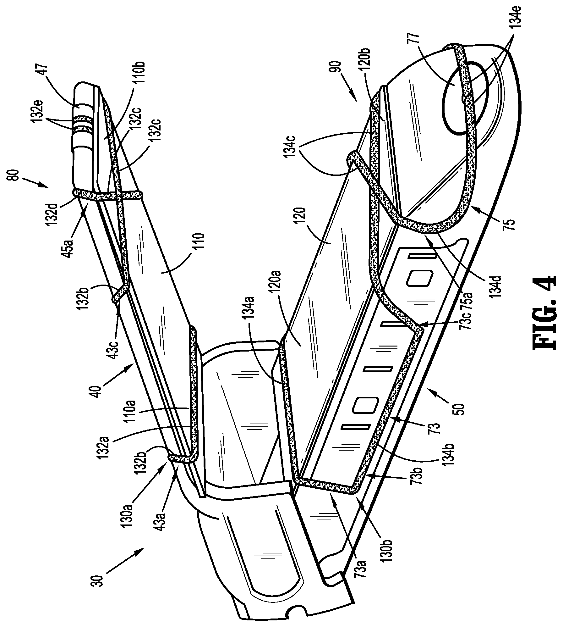
FIG. 4 is an end, perspective view of the jaw assembly of FIG. 3, including surgical buttresses releasably secured to the anvil and staple cartridge assemblies via retention members in accordance with an embodiment of the present disclosure;
FIG. 5 is a side, perspective view of a jaw assembly for use with the surgical stapling apparatus of FIG. 1, in accordance with another embodiment of the present disclosure; and
FIG. 6 is an end, perspective view of the jaw assembly of FIG. 5, including surgical buttresses releasably secured to anvil and staple cartridge assemblies of the jaw assembly via retention members in accordance with another embodiment of the present disclosure.
DETAILED DESCRIPTION OF THE EMBODIMENTS
Various exemplary embodiments of the present disclosure are discussed herein below in terms of surgical buttress retention systems for releasably securing surgical buttresses to a surgical stapling apparatus. The surgical buttresses described herein may be used in sealing a wound by approximating the edges of wound tissue between a staple cartridge assembly and an anvil assembly of a surgical stapling apparatus which includes at least one surgical buttress. The surgical buttress is releasably attached to the surgical stapling apparatus by a surgical buttress retention system that is configured to secure both proximal and distal portions of the surgical buttress to the surgical stapling apparatus and to release both the proximal and distal portions of the surgical buttress from the surgical stapling apparatus during cutting of only the proximal portion of the surgical buttress during firing of the surgical stapling apparatus.
Embodiments of the presently disclosed surgical buttress retention systems will now be described in detail with reference to the drawing figures wherein like reference numerals identify similar or identical elements. Throughout this description, the term "proximal" refers to a portion of a structure, or component thereof, that is closer to a user, and the term "distal" refers to a portion of the structure, or component thereof, that is farther from the user. Directional reference terms, such as "top," "bottom," "side," and the like, are intended to ease description of the embodiments and are not intended to have any limiting effect on the ultimate orientations of a structure or any parts thereof.
Referring now to FIGS. 1 and 2, an exemplary surgical stapling apparatus or surgical stapler 1 is shown for use in stapling tissue and applying one or more buttress materials or surgical buttresses to the tissue. The surgical stapling apparatus 1 generally includes a handle assembly 10, an elongate tubular body portion 20 extending distally from the handle assembly 10, and an end effector or jaw assembly 30 extending distally from the elongate tubular body portion 20. The jaw assembly 30 includes an anvil assembly 40 and a staple cartridge assembly 50. The jaw assembly 30 may be permanently affixed to the elongate tubular body portion 20 or may be detachable with respect to the elongate tubular body portion 20 and thus, replaceable with a new jaw assembly 30. The anvil assembly 40 and/or the staple cartridge assembly 50 is pivotable with respect to the elongate tubular body portion 20 such that the anvil and staple cartridge assemblies 40, 50 are movable between an open position in which the anvil and staple cartridge assemblies 40, 50 are spaced apart with respect to each other and a closed position in which the anvil and staple cartridge assemblies 40, 50 are substantially adjacent each other.
The handle assembly 10 includes a stationary handle member 12a, a movable handle member 12b, and a barrel portion 14. An articulation lever 16 is mounted on the forward end of the barrel portion 14 to facilitate articulation of the jaw assembly 30. A rotatable member 18 is also mounted on the forward end of the barrel portion 14, adjacent the articulation lever 16. Rotation of the rotatable member 18 relative to the barrel portion 14 rotates the elongate tubular body portion 20 and the jaw assembly 30 relative to the handle assembly 10 so as to properly orient the anvil and staple cartridge assemblies 40, 50 relative to tissue to be stapled. A pair of knobs 19 is movably positionable along the barrel portion 14. The pair of knobs 19 is advanced distally to approximate or close the anvil and staple cartridge assemblies 40, 50, relative to each other, and retracted proximally to unapproximate or open the anvil and staple cartridge assemblies 40, 50, with respect to each other. Actuation of the movable handle member 12b applies lines of staples 58 (FIG. 3) to tissue captured between the anvil and staple cartridge assemblies 40, 50.
As seen in FIG. 3, the anvil assembly 40 includes an anvil plate 42 having a central longitudinal slot 41 formed therein, and a cover plate 44 secured over the anvil plate 42 such that the cover plate 44 defines a top or outwardly facing surface 46 of the anvil assembly 40. The anvil plate 42 may include a plurality of staple forming pockets/cavities (not shown) defined in an inward or tissue facing surface 48 thereof.
The staple cartridge assembly 50 includes a cartridge carrier 52 defining an elongated support channel 53 configured and dimensioned to selectively receive a staple cartridge 54 therein. The staple cartridge 54 is removable and replaceable in the cartridge carrier 52 of the staple cartridge assembly 50. The staple cartridge 54 includes an inward or tissue facing surface 56 defining staple pockets or retention slots 55 formed therein for receiving a plurality of fasteners or staples 58 and staple pushers 60. A central longitudinal slot 57 is formed in and extends along a substantial length of the staple cartridge 54 to facilitate passage of a knife blade 62 of a drive bar 64 therethrough. During operation of the surgical stapler 1, an actuation sled 66 translates through the staple cartridge 54 to advance cam wedges 68 of the actuation sled 66 into sequential contact with the staple pushers 60, to cause the staple pushers 60 to translate vertically within the staple pockets 55 and urge the staples 58 from the staple pockets 55 towards the tissue facing surface 48 of the anvil plate 42 of the anvil assembly 40.
For a detailed description of the structure and function of exemplary surgical stapling apparatus, reference may be made to U.S. Pat. Nos. 6,330,965, 6,241,139, and 7,819,896, the entire contents of each of which are incorporated herein by reference. It should be appreciated that principles of the present disclosure are equally applicable to surgical stapling apparatus having other configurations such as, for example, the types described in U.S. Pat. Nos. 7,128,253, 7,334,717, and 5,964,394, the entire contents of each of which are incorporated herein by reference. Accordingly, it should be understood that a variety of surgical stapling apparatus may be utilized with the surgical buttress retention systems of the present disclosure. For example, laparoscopic or open staplers, such as, for example, GIA.TM., Endo GIA.TM., TA.TM., and Endo TA.TM. staplers and/or linear and radial reloads with, for example, Tri-Staple.TM. technology, available through Medtronic (North Haven, Conn.) may be utilized with the surgical buttress retention systems of the present disclosure.
With continued reference to FIG. 3, the anvil assembly 40 further includes proximal anvil guide slots 43, distal anvil guide slots 45, and an anvil plug 47. The proximal anvil guide slots 43 and the distal anvil guide slots 45 are recessed in the outer surface 46 of the anvil cover 44. The proximal anvil guide slots 43 are disposed in opposed sides of the anvil cover 44, and are mirror images of each other. The proximal anvil guide slots 43 have a generally U-shaped configuration in that each of the proximal anvil guide slots 43 include a central segment 43b extending longitudinally along the anvil cover 44 and a first or proximal leg segment 43a and a second or distal leg segment 43c each extending at an angle with respect to the central segment 43b to side edges 44a, 44b of the anvil cover 44. The first and second leg segments 43a, 43c may extend at the same or different angles with respect to the central segment 43b. In embodiments, the first leg segment 43a is disposed at about a 90.degree. angle with respect to the central segment 43b and the second leg segment 43c is disposed at about a 135.degree. angle with respect to the central segment 43b. In some embodiments, as shown in FIG. 2, the first leg segment 43a is disposed at about a 90.degree. angle with respect to the central segment 43b and the second leg segment 43c' is disposed at about a 90.degree. angle with respect to the central segment 43b. The anvil plate 42 may include recesses 42c defined in side edges 42a, 42b thereof that are aligned with the first and second leg segments 43a, 43b of the proximal anvil guide slots 43.
The distal anvil guide slots 45 are disposed in opposed sides of the anvil cover 44 in longitudinally spaced relation relative to the proximal anvil guide slots 43, and are also mirror images of each other. The distal anvil guide slots 45 have a generally L-shaped configuration in that each of the distal anvil guide slots 45 have first and second leg segments 45a, 45b that are disposed at an angle with respect to each other. In embodiments, the first leg segment 45a is disposed at about a 135.degree. angle with respect to the second leg segment 45b which extends longitudinally along the anvil cover 44 to a distal end 44c thereof. In some embodiments, as shown in FIG. 2, the first leg segment 45a' is disposed at about a 90.degree. angle with respect to the second leg segment 45b which extends longitudinally along the anvil cover 44 to the distal end 44c thereof.
The anvil plug 47 has a cylindrical body 47a that is configured to releasably engage the distal end 44c of the anvil cover 44. In embodiments, the anvil plug 47 is press fit into an anvil recess 49 defined in the distal end 44c of the anvil cover 44. The anvil plug 47 may include an aperture 47b defined therethrough.
With continued reference to FIG. 3, the staple cartridge assembly 50 further includes proximal cartridge guide slots 73, distal cartridge guide slots 75, and a cartridge plug 77. The proximal cartridge guide slots 73 are recessed in side surfaces 52a, 52b of the cartridge carrier 52, and the distal cartridge guide slots 77 are recessed in an outer surface 54a of the staple cartridge 54. While only one of the proximal and distal cartridge guide slots 73, 75 are shown in FIG. 3, it should be understood that the other of the proximal and distal cartridge guide slots 73, 75 are substantially identical to ones shown and are disposed in oppose sides of the respective cartridge carrier 52 and staple cartridge 54 as mirror images of the ones shown.
The proximal cartridge guide slots 73 have a generally U-shaped configuration in that each of the proximal cartridge guide slots 73 include a central segment 73b extending longitudinally along the cartridge carrier 52 and a first or proximal leg segment 73a and a second or distal leg segment 73c each extending at an angle with respect to the central segment 73b. The first and second leg segments 73a, 73c may extend at the same or different angles with respect to the central segment 73b. In embodiments, the first leg segment 73a is disposed at about a 90.degree. angle with respect to the central segment 73b and the second leg segment 73c is disposed at about a 135.degree. angle with respect to the central segment 73b. In some embodiments, as shown in FIG. 2, the first leg segment 73a is disposed at about a 90.degree. angle with respect to the central segment 73b and the second leg segment 73c' is disposed at about a 90.degree. angle with respect to the central segment 73b.
The distal cartridge guide slots 75 have a generally L-shaped configuration in that each of the distal cartridge guide slots 75 have first and second leg segments 75a, 75b that are disposed at an angle with respect to each other. In embodiments, the first leg segment 75a is disposed at about a 135.degree. angle with respect to the second leg segment 75b which extends transversely across a distal portion 54b of the staple cartridge 54. In some embodiments, as shown in FIG. 2, the first leg segment 75a' is disposed at about a 90.degree. angle with respect to the second leg segment 75b which extends transversely across the distal portion 54b of the staple cartridge 54.
The cartridge plug 77 has a cylindrical body 77a that is configured to releasably engage a cartridge recess 51 defined in the distal portion 54b of the staple cartridge 54. In embodiments, the cartridge plug 77 is press fit into the cartridge recess 51 of the staple cartridge 54. The cartridge plug 77 may include an aperture 77b defined therethrough.
With reference now to FIG. 4, surgical buttresses 110, 120 (also referred to herein as anvil buttress 110 and cartridge buttress 120) are releasably attached to the respective anvil and staple cartridge assemblies 40, 50 of the jaw assembly 30 of the surgical stapler 1 (FIG. 1) by retention members 130a, 130b (also referred to herein as anvil retention member 130a and cartridge retention member 130b). The surgical buttresses 110, 120 are fabricated from biocompatible materials which are bioabsorbable or non-absorbable, natural or synthetic materials. It should be understood that any combination of natural, synthetic, bioabsorbable, and/or non-bioabsorbable materials may be used to form the surgical buttresses 110, 120. The surgical buttresses 110, 120 may be formed from the same material or different materials.
The surgical buttresses 110, 120 may be porous, non-porous, or combinations thereof. Suitable porous structures include, for example, fibrous structures (e.g., knitted structures, woven structures, and non-woven structures) and/or foams (e.g., open or closed cell foams). Suitable non-porous structures include, for example, films. The surgical buttresses 110, 120 described herein may be a single porous or non-porous layer, or include a plurality of layers including any combination of porous and non-porous layers. For example, a surgical buttress may include multiple porous and non-porous layers that are stacked in an alternating manner. In another example, a surgical buttress may be formed in a "sandwich-like" manner wherein the outer layers of the surgical buttress are porous and the inner layer(s) are non-porous, or vice versa. The surgical buttresses 110, 120 may have the same or a different structure of layer(s).
Porous layer(s) in a surgical buttress may enhance the ability of the surgical buttress to absorb fluid, reduce bleeding, and seal a wound. Also, the porous layer(s) may allow for tissue ingrowth to fix the surgical buttress in place. Non-porous layer(s) in a surgical buttress may enhance the ability of the surgical buttress to resist tears and perforations during the manufacturing, shipping, handling, and stapling processes. Also, non-porous layer(s) may retard or prevent tissue ingrowth from surrounding tissues thereby acting as an adhesion barrier and preventing the formation of unwanted scar tissue.
The retention members 130a, 130b are fabricated from biocompatible materials which are any combination of natural, synthetic, bioabsorbable, and/or non-bioabsorbable materials. Each of the retention members 130a, 130b is a single continuous elongated structure, and may be in the form of a suture, thread, filament, etc.
With continued reference to FIG. 4, in conjunction with FIG. 3, the anvil buttress 110 is releasably secured to the anvil assembly 40 via an anvil buttress retention system 80 including the anvil retention member 130a in cooperation with the proximal and distal anvil guide slots 43, 45 (FIG. 3) and the anvil plug 47 of the anvil assembly 40. With the anvil buttress 110 positioned on the tissue facing surface 48 of the anvil plate 42, a central or first portion 132a of the anvil retention member 130a is positioned across a proximal portion 110a of the anvil buttress 110 and aligned with the first leg segments 43a of the proximal anvil guide slots 43 such that second portions 132b of the anvil retention member 130a are positioned within the proximal anvil guide slots 43. In embodiments in which the first leg segments 43a of the proximal anvil guide slots 43 are disposed at about a 90.degree. angle with respect to the central segment 43b, the first portion 132a of the anvil retention member 130a will be retained transversely across the proximal portion 110a of the anvil buttress 110.
Third portions 132c of the anvil retention member 130a extend from the proximal anvil guide slots 43 and cross each other over a distal portion 110b of the anvil buttress 110, and fourth portions 132d of the anvil retention member 130a are positioned within the distal anvil guide slots 45. In embodiments in which the second leg segments 43c of the proximal anvil guide slots 43 and the first leg segments 45a of the distal anvil guide slots 45 are disposed at about 135.degree. angles, as described above, the anvil retention member 130a follows an aligned path for the cross over transition over the distal portion 110b of the anvil buttress 110. Fifth or end portions 132e of the anvil retention member 130a are coupled to the anvil plug 47 to retain the anvil retention member 130a on the anvil assembly 40 and over the anvil buttress 110.
The fifth portions 132e of the anvil retention member 130a may be wound around the anvil plug 47 to tension the anvil retention member 130a on the anvil assembly 40. The fifth portions 132e may be wound around the anvil plug 47 prior to positioning the anvil plug 47 within the anvil recess 49 or while the anvil plug 47 is positioned within the anvil recess 49 (e.g., by rotating the anvil plug 47 relative to the anvil cover 44). In embodiments, the fifth portions 132e are passed into the aperture 47b of the anvil plug 47 and retained therein such that the anvil plug 47 may be rotated relative to the anvil cover 44 to tension the anvil retention member 130a about the anvil buttress 110 and the anvil assembly 40.
The configuration of the proximal and distal anvil guide slots 43, 45 as well as the positioning of the anvil retention member 130a therethrough minimizes and/or prevents pinch points along the anvil retention member 130a to allow for smooth insertion, tensioning, and deployment of the anvil retention member 130a. Moreover, the depth of the proximal and distal anvil guide slots 43, 45 may be configured to ensure that the anvil retention member 130a is flush with the outer surfaces of the anvil assembly 40 to reduce and/or eliminate the occurrence of the anvil retention member 130a moving out of alignment with the proximal and/or distal anvil guide slots 43, 45 during, for example, translation of the anvil retention member 130a relative to the anvil assembly 40 during tensioning thereof and/or during insertion into tissue when outside forces may act upon the jaw assembly 30.
As also shown in FIG. 4, in conjunction with FIG. 3, the cartridge buttress 120 is releasably secured to the staple cartridge assembly 50 via a cartridge buttress retention system 90 including the cartridge retention member 130b in cooperation with the proximal and distal cartridge guide slots 73, 75 (FIG. 3), and the cartridge plug 77 of the staple cartridge assembly 50. With the cartridge buttress 120 positioned on the tissue facing surface 56 of the staple cartridge 54, a central or first portion 134a of the cartridge retention member 130b is positioned across a proximal portion 120a of the cartridge buttress 120 and aligned with the first leg segments 73a of the proximal cartridge guide slots 73 such that second portions 134b of the cartridge retention member 130b are positioned within the proximal cartridge guide slots 73. In embodiments in which the first leg segments 73a of the proximal cartridge guide slots 73 are disposed at about a 90.degree. angle with respect to the central segment 73b, the first portion 134a of the cartridge retention member 130b will be retained transversely across the proximal portion 120b of the cartridge buttress 120.
Third portions 134c of the cartridge retention member 130b extend from the proximal cartridge guide slots 73 and cross each other over a distal portion 120b of the cartridge buttress 120, and fourth portions 134d of the cartridge retention member 130b are positioned within the distal cartridge guide slots 75. In embodiments in which the second leg segments 73c of the proximal cartridge guide slots 73 and the first leg segments 75a of the distal cartridge guide slots 75 are disposed at about 135.degree. angles, as described above, the buttress retention member 130b follows an aligned path for the cross over transition over the distal portion 120b of the cartridge buttress 120. Fifth or end portions 134e of the cartridge retention member 130b are coupled to the cartridge plug 77 to retain the cartridge retention member 130b on the staple cartridge assembly 50 and over the cartridge buttress 120.
The fifth portions 134e of the cartridge retention member 130b may be wound around the cartridge plug 77 to tension the cartridge retention member 130b on the staple cartridge assembly 50. The fifth portions 134e may be wound around the cartridge plug 77 prior to positioning the cartridge plug 77 within the cartridge recess 51 or while the cartridge plug 77 is positioned within the cartridge recess 51 (e.g., by rotating the cartridge plug 77 relative to the staple cartridge 54). In embodiments, the fifth portions 134e are passed through the aperture 77b of the cartridge plug 77 and retained therein such that the cartridge plug 77 may be rotated relative to the staple cartridge 54 to tension the cartridge retention member 130b about the cartridge buttress 120 and the staple cartridge assembly 50.
The configuration of the proximal and distal cartridge guide slots 73, 75 as well as the positioning of the cartridge retention member 130b therethrough minimizes and/or prevents pinch points along the cartridge retention member 130b to allow for smooth insertion, tensioning, and deployment of the cartridge retention member 130b. Moreover, the depth of the proximal and distal cartridge guide slots 73, 75 may be configured to ensure that the cartridge retention member 130b is flush with the outer surfaces of the staple cartridge assembly 50 to reduce and/or eliminate the occurrence of the cartridge retention member 130b moving out of alignment with the proximal and/or distal cartridge guide slots 73, 75 during, for example, translation of the cartridge retention member 130b relative to the staple cartridge assembly 50 during tensioning thereof and/or during insertion into tissue when outside forces may act upon the jaw assembly 30.
In a method of loading the anvil and cartridge buttresses 110, 120 onto the anvil and staple cartridge assemblies 40, 50, the anvil and cartridge buttresses 110, 120 are positioned over the respective tissue facing surfaces 48, 56 of the anvil and staple cartridge assemblies 40, 50, and then the anvil and cartridge retention members 130a, 130b are engaged with the respective proximal anvil and cartridge guide slots, 43, 73, the distal anvil and cartridge guide slots, 45, 75, and the anvil and cartridge plug members 47, 77, as described above. The anvil and cartridge retention members 130a, 130b are tensionable via the anvil and cartridge plug members 47, 77, as also described above. Alternatively, the anvil and buttress retention systems 80, 90 may be assembled, the anvil and cartridge buttresses 110, 120 may be slid under the respective anvil and cartridge retention members 130a, 130b, and then the anvil and cartridge retention members 130a, 130b may be tensioned over the anvil and cartridge buttresses 110, 120. The jaw assembly 30 is thus loaded and ready for use, as shown in FIG. 4.
In operation, with the anvil and cartridge buttress 110, 120 loaded onto the anvil and staple cartridge assemblies 40, 50, as described above, the surgical stapler 1 is used in accordance with methods known by those skilled in the art. Once the anvil and staple cartridge assemblies 40, 50 are clamped onto tissue (e.g., moved from the open position shown, for example, in FIG. 4, to the closed position, shown, for example, in FIG. 2), the surgical stapler 1 is fired. In firing the surgical stapler 1, the drive bar 64 is advanced distally through the jaw assembly 30 urging the staple pushers 60 upwardly which, in turn, drive the staples 58 out of the staple pockets 55 and through the anvil and cartridge buttresses 110, 120 as well as the captured tissue, thereby stapling the anvil and cartridge buttresses 110, 120 to the tissue.
During firing, the knife blade 62 of the drive bar 64 travels distally while substantially simultaneously cutting and dividing the tissue and the anvil and cartridge buttresses 110, 120 disposed between the rows of now formed staples 58. As the first portions 132a, 134a of the anvil and cartridge retention members 130a, 130b extend across the respective proximal portions 110a, 120a of the anvil and cartridge buttresses 110, 120 above the respective central longitudinal slots 41, 57 of the anvil and staple cartridge assemblies 40, 50, the knife blade 62 also cuts through the first portions 132a, 134a of the anvil and cartridge retention members 130a, 130b. The proximal cut of the first portions 132a, 134a of the anvil and cartridge retention members 130a, 130b releases the tension on the anvil and cartridge retention members 130a, 130b and loosens the anvil and cartridge retention members 130a, 130b, freeing the anvil and cartridge buttresses 110, 120 from the anvil and staple cartridge assemblies 40, 50.
When firing is complete, after a partial or full firing stroke, and the anvil and staple cartridge assemblies 40, 50 are unclamped, the anvil and cartridge buttresses 110, 120, which are now stapled to the tissue, pull away from the anvil and staple cartridge assemblies 40, 50, while the anvil and buttress retention members 130a, 130b are retained on the anvil and staple cartridge assemblies 40, 50 (via the anvil and cartridge plugs 47, 77) and removed from the surgical site with the removal of the jaw assembly 30 therefrom. Accordingly, the anvil and cartridge buttresses 110, 120 are released from the surgical stapler 1 after a partial or full firing stroke by requiring only a single proximal cut of the anvil and cartridge retention members 130a, 130b. Further, as cutting of the tissue follows staple formation, the proximal cut of the anvil and cartridge retention members 130a, 130b ensures that any tissue that is cut is also stapled and reinforced with the anvil and cartridge buttresses 110, 120.
With reference now to FIGS. 5 and 6, a jaw assembly 30' in accordance with another embodiment of the present disclosure is shown. The jaw assembly 30' has an anvil assembly 40' including an anvil plate 42 and an anvil cover 44', and a staple cartridge assembly 50' including a carrier cartridge 52' and a staple cartridge 54'. The jaw assembly 30' is substantially similar to the jaw assembly 30 and will be described in detail herein to the extent necessary to describe the differences in construction and operation thereof.
The anvil assembly 40' includes a proximal anvil guide assembly 140, a distal anvil guide assembly 144, and an anvil plug 47. The proximal guide assembly 140 includes proximal anvil guide cleats or bumpers 142a disposed on opposed sides of the anvil cover 44'. The proximal anvil guide cleats 142a protrude or extend from an outer surface 46' of the anvil cover 44' and have a rounded shape. The proximal guide assembly 140 further includes distal anvil guide cleats or bumpers 142b disposed on opposed sides of the anvil cover 44' in longitudinally spaced and aligned relation relative to the proximal anvil guide cleats 142a. The distal anvil guide cleats 142b also protrude or extend from an outer surface 46' of the anvil cover 44' and have a rounded shape. The proximal and distal anvil guide cleats 142a, 142b may be formed from a soft and/or flexible material (e.g., a polymeric material) to minimize trauma to tissue during insertion of the jaw assembly 30' into a surgical site.
The distal anvil guide assembly 144 includes anvil guide shoulders 146 extending from the outer surface 46' of the anvil cover 44. The anvil guide shoulders 146 are disposed on opposed sides of the anvil cover 44' and are images of each other. The anvil guide shoulders 146 have a generally L-shaped or C-shaped configuration including soft, rounded edges. The anvil guide shoulders 146 may also be formed from a soft and/or flexible material.
The staple cartridge assembly 50' includes a proximal cartridge guide assembly 150, a distal cartridge guide assembly 154, and a cartridge plug 77. The proximal cartridge guide assembly 150 includes proximal and distal cartridge guide cleats or bumpers 152a, 152b disposed on opposed sides of the cartridge carrier 52', and the distal cartridge guide assembly 154 includes cartridge guide shoulders 156 disposed on opposed sides of the staple cartridge 54'. While only one of the proximal and distal cartridge guide cleats 152a, 152b, and cartridge guide shoulders 156 are shown, it should be understood that the other of the respective proximal and distal cartridge guide cleats 152a, 152b, and cartridge guide shoulders 156, are substantially identical to the ones shown and are positioned on the opposing side of the cartridge carrier 52' and staple cartridge 54' as mirror images of each other.
The proximal and distal cartridge guide cleats 152a, 152b protrude or extend from side surfaces 52a', 52b' of the cartridge carrier 52', and each has a rounded shape. The distal cartridge guide cleats 152b are longitudinally spaced from, and aligned with, the proximal cartridge guide cleats 152a. The cartridge guide shoulders 156 extend from opposed sides of a distal portion 54b' of the staple cartridge 54', and each has a generally L-shaped or C-shaped configuration including soft, rounded edges. The proximal and distal cartridge guide cleats 152a, 152b, and/or the cartridge guide shoulders 156 may be formed from a soft and/or flexible material (e.g., a polymeric material) to minimize trauma to tissue during insertion of the jaw assembly 30' into a surgical site.
With continued reference to FIGS. 5 and 6, an anvil buttress 110 is releasably secured to the anvil assembly 40' via an anvil buttress retention system 180 including an anvil retention member 130a in cooperation with the proximal and distal anvil guide assemblies 140, 142, and the anvil plug 47 of the anvil assembly 40'. With the anvil buttress 110 positioned on the tissue facing surface 48 (FIG. 3) of the anvil plate 42, a central or first portion 132a of the anvil retention member 130a is positioned across a proximal portion 110a of the anvil buttress 110 and aligned with proximally facing sides of the proximal anvil guide cleats 142a such that second portions 132b of the anvil retention member 130a extend around the proximal anvil guide cleats 142a, longitudinally across the outer surface 46' of the anvil cover 44', and around the distal anvil guide cleats 142b.
Third portions 132c of the anvil retention member 130a extend from distally facing sides of the distal anvil guide cleats 142b and cross each other over a distal portion 110b of the anvil buttress 110. Fourth portions 132d of the anvil retention member 130a are positioned around the anvil guide shoulders 146, and fifth or end portions 132e of the anvil retention member 130a are coupled to the anvil plug 47 to retain the anvil retention member 130a on the anvil assembly 40' and over the anvil buttress 110, as described above.
The configuration of the proximal and distal anvil guide cleats 142a, 142b and the anvil guide shoulders 146 (e.g., the rounded sides and/or material selection), as well as the positioning of the anvil retention member 130a therearound minimizes and/or prevents pinch points along the anvil retention member 130a to allow for smooth insertion, tensioning, and deployment of the anvil retention member 130a.
As also shown in FIGS. 5 and 6, a cartridge buttress 120 is releasably secured to the staple cartridge assembly 50' via a cartridge buttress retention system 190 including a cartridge retention member 130b in cooperation with the proximal and distal cartridge guide assemblies 150, 152, and the cartridge plug 77 of the staple cartridge assembly 50'. With the cartridge buttress 120 positioned on the tissue facing surface 56 (FIG. 3) of the staple cartridge 54', a central or first portion 134a of the cartridge retention member 130b is positioned across a proximal portion 120a of the cartridge buttress 120 and aligned with proximally facing sides of the proximal cartridge guide cleats 152a such that second portions 134b of the cartridge retention member 130b extend around the proximal cartridge guide cleats 152a, longitudinally along the cartridge carrier 52', and around the distal cartridge guide cleats 152b.
Third portions 134c of the cartridge retention member 130b extend from distally facing sides of the distal anvil guide cleats 152b and cross each other over a distal portion 120b of the cartridge buttress 120. Fourth portions 134d of the cartridge retention member 130b are positioned around the cartridge guide shoulders 156, and fifth or end portions 134e of the cartridge retention member 130b are coupled to the cartridge plug 77 to retain the cartridge retention member 130b on the staple cartridge assembly 50' and over the cartridge buttress 120, as described above.
The configuration of the proximal and distal cartridge guide cleats 152a, 152b and the cartridge guide shoulders 156 (e.g., the rounded sides and/or material selection), as well as the positioning of the cartridge retention member 130b therearound minimizes and/or prevents pinch points along the cartridge retention member 130b to allow for smooth insertion, tensioning, and deployment of the cartridge retention member 130b.
A surgical stapler 1 including the jaw assembly 30' having anvil and cartridge buttresses 110, 120 loaded onto the anvil and staple cartridge assemblies 40', 50' via the anvil and cartridge buttress retention systems 180, 190, as described above, is operated in the same manner as described above with respect to the surgical stapler 1 including the jaw assembly 30 having anvil and cartridge buttresses 110, 120 loaded onto the anvil and staple cartridge assemblies 40, 50 via the anvil and cartridge buttress retention systems 80, 90.
It should be understood that the anvil buttress retention systems 80, 180, the cartridge buttress retention systems 90, 190, and/or components thereof, may be used together. For example, the proximal anvil guide slots 43 of the anvil buttress retention system 80 may be used with the proximal and distal anvil guide cleats 142a, 142b of the anvil buttress retention system 180, and/or the distal anvil guide slots 45 of the anvil buttress retention system 80 may be used with the anvil guide shoulders 146 of the anvil buttress retention system 180. Similarly, the proximal cartridge guide slots 73 of the cartridge buttress retention system 90 may be used with the proximal and distal cartridge guide cleats 152a, 152b of the cartridge buttress retention system 190, and/or the distal cartridge guide slots 75 of the cartridge buttress retention system 90 may be used with the cartridge guide shoulders 156 of the cartridge buttress retention system 190. As another example, the proximal and distal anvil guide cleats 142a, 142b of the anvil buttress retention system 180 may be used with the central segments 43b of the proximal anvil guide slots 43 of the anvil buttress retention system 80, and/or the anvil guide shoulders 146 of the anvil buttress retention system 180 may be used with the second leg segments 45b of the distal anvil guide slots 45 of the anvil buttress retention system 80. Similarly, the proximal and distal cartridge guide cleats 152a, 152b of the cartridge buttress retention system 190 may be used with the central segments 73b of the proximal cartridge guide slots 73 of the cartridge buttress retention system 90, and/or the cartridge guide shoulders 156 of the cartridge buttress retention system 190 may be used with the second leg segments 75b of the distal cartridge guide slots 75 of the cartridge buttress retention system 90. A variety of combinations of the components of the anvil and cartridge buttress retention systems are envisioned, provided such result in smooth insertion, tensioning, and deployment of the retention members, as described above.
It should be further understood that while the surgical stapler 1 is shown including both the anvil and cartridge buttresses 110, 120, the surgical stapler 1 may include only the anvil buttress 110 or the cartridge buttress 120 depending on, for example, the surgical application and/or desired placement of the buttress material relative to tissue as should be understood by those skilled in the art. The anvil buttress 110 and/or the cartridge buttress 120 may be pre-loaded (e.g., by the manufacturer) onto the anvil assembly 40, 40' and/or staple cartridge assembly 50, 50' of the jaw assembly 30, 30'. Additional or replacement anvil buttresses 110 and/or cartridge buttresses 120 may be secured to the respective anvil assembly 40, 40' and/or staple cartridge assembly 50, 50' as needed or desired.
The surgical buttresses and anvil buttress retention systems described herein may also be configured for use with other surgical apparatus, such as electromechanical surgical devices as described, for example, in U.S. Patent Appl. Pub. Nos. 2015/0157320 and 2015/0157321, the entire contents of each of which are incorporated herein by reference.
Persons skilled in the art will understand that the systems, devices, and methods specifically described herein and illustrated in the accompanying figures are non-limiting exemplary embodiments, and that the description, disclosure, and figures should be construed merely exemplary of particular embodiments. It is to be understood, therefore, that the present disclosure is not limited to the precise embodiments described, and that various other changes and modifications may be effected by one skilled in the art without departing from the scope or spirit of the disclosure. Additionally, it is envisioned that the elements and features illustrated or described in connection with one exemplary embodiment may be combined with the elements and features of another exemplary embodiment without departing from the scope of the present disclosure, and that such modifications and variations are also intended to be included within the scope of the present disclosure. Accordingly, the subject matter of the present disclosure is not to be limited by what has been particularly shown and described.
* * * * *
D00000
D00001
D00002
D00003
D00004
XML
uspto.report is an independent third-party trademark research tool that is not affiliated, endorsed, or sponsored by the United States Patent and Trademark Office (USPTO) or any other governmental organization. The information provided by uspto.report is based on publicly available data at the time of writing and is intended for informational purposes only.
While we strive to provide accurate and up-to-date information, we do not guarantee the accuracy, completeness, reliability, or suitability of the information displayed on this site. The use of this site is at your own risk. Any reliance you place on such information is therefore strictly at your own risk.
All official trademark data, including owner information, should be verified by visiting the official USPTO website at www.uspto.gov. This site is not intended to replace professional legal advice and should not be used as a substitute for consulting with a legal professional who is knowledgeable about trademark law.