Interlocking buttress material retention system
(Prommersberger) Stopek December 31, 2
U.S. patent number 8,616,430 [Application Number 13/652,502] was granted by the patent office on 2013-12-31 for interlocking buttress material retention system. This patent grant is currently assigned to Covidien LP. The grantee listed for this patent is Covidien LP. Invention is credited to Megan L. (Prommersberger) Stopek.


| United States Patent | 8,616,430 |
| (Prommersberger) Stopek | December 31, 2013 |
Interlocking buttress material retention system
Abstract
A surgical stapler is provided having a pair of jaws including a staple containing cartridge and an anvil. Buttress material is releasable affixed to the staple containing cartridge and the anvil. One of the jaws includes a pair of longitudinal projections at a first end of the jaw and configured to frictionally engage corresponding slots in a first end the buttress material. One of the jaws includes a post at a second end of the jaw. The buttress material includes a hole in a second end of the buttress material for receipt of the post.
| Inventors: | (Prommersberger) Stopek; Megan L. (Guilford, CT) | ||||||||||
|---|---|---|---|---|---|---|---|---|---|---|---|
| Applicant: |
|
||||||||||
| Assignee: | Covidien LP (Mansfield,
MA) |
||||||||||
| Family ID: | 39768705 | ||||||||||
| Appl. No.: | 13/652,502 | ||||||||||
| Filed: | October 16, 2012 |
Prior Publication Data
| Document Identifier | Publication Date | |
|---|---|---|
| US 20130037600 A1 | Feb 14, 2013 | |
Related U.S. Patent Documents
| Application Number | Filing Date | Patent Number | Issue Date | ||
|---|---|---|---|---|---|
| 13307581 | Nov 30, 2011 | 8308046 | |||
| 13051475 | Dec 27, 2011 | 8083119 | |||
| 12687400 | Mar 22, 2011 | 7909224 | |||
| 11820239 | Feb 23, 2010 | 7665646 | |||
| Current U.S. Class: | 227/176.1; 227/180.1; 227/19 |
| Current CPC Class: | A61B 17/0682 (20130101); A61B 17/07292 (20130101); A61B 17/105 (20130101); A61B 17/32 (20130101); A61B 17/0686 (20130101); A61B 17/072 (20130101); A61B 17/07207 (20130101); A61B 17/068 (20130101); A61B 2017/00004 (20130101); A61B 2017/320052 (20130101); A61B 2017/00893 (20130101); A61B 2017/07214 (20130101) |
| Current International Class: | A61B 17/068 (20060101) |
| Field of Search: | ;227/19,175.1,176.1,178.1,180.1 ;606/139,151,219 ;361/773,776 ;349/150 |
References Cited [Referenced By]
U.S. Patent Documents
| 3054406 | September 1962 | Usher |
| 3079606 | March 1963 | Bobrov et al. |
| 3124136 | March 1964 | Usher |
| 3490675 | January 1970 | Green et al. |
| 3499591 | March 1970 | Green |
| 4347847 | September 1982 | Usher |
| 4354628 | October 1982 | Green |
| 4429695 | February 1984 | Green |
| 4452245 | June 1984 | Usher |
| 4605730 | August 1986 | Shalaby et al. |
| 4655221 | April 1987 | Devereux |
| 4834090 | May 1989 | Moore |
| 4838884 | June 1989 | Dumican et al. |
| 4930674 | June 1990 | Barak |
| 5002551 | March 1991 | Linsky et al. |
| 5014899 | May 1991 | Presty et al. |
| 5040715 | August 1991 | Green et al. |
| 5065929 | November 1991 | Schulze et al. |
| 5205459 | April 1993 | Brinkerhoff et al. |
| 5263629 | November 1993 | Trumbull et al. |
| 5307976 | May 1994 | Olson et al. |
| 5312023 | May 1994 | Green et al. |
| 5314471 | May 1994 | Brauker et al. |
| 5318221 | June 1994 | Green et al. |
| 5326013 | July 1994 | Green et al. |
| 5332142 | July 1994 | Robinson et al. |
| 5344454 | September 1994 | Clarke et al. |
| 5392979 | February 1995 | Green et al. |
| 5397324 | March 1995 | Carroll et al. |
| 5425745 | June 1995 | Green et al. |
| 5441193 | August 1995 | Gravener |
| 5441507 | August 1995 | Wilk |
| 5468253 | November 1995 | Bezwada et al. |
| 5503638 | April 1996 | Cooper et al. |
| 5542594 | August 1996 | McKean et al. |
| 5549628 | August 1996 | Cooper et al. |
| 5575803 | November 1996 | Cooper et al. |
| 5653756 | August 1997 | Clarke et al. |
| 5683809 | November 1997 | Freeman et al. |
| 5690675 | November 1997 | Sawyer et al. |
| 5702409 | December 1997 | Rayburn et al. |
| 5752965 | May 1998 | Francis et al. |
| 5762256 | June 1998 | Mastri et al. |
| 5766188 | June 1998 | Igaki |
| 5769892 | June 1998 | Kingwell |
| 5782396 | July 1998 | Mastri et al. |
| 5799857 | September 1998 | Robertson et al. |
| 5810855 | September 1998 | Rayburn et al. |
| 5814057 | September 1998 | Oi et al. |
| 5833695 | November 1998 | Yoon |
| 5843096 | December 1998 | Igaki et al. |
| 5895412 | April 1999 | Tucker |
| 5895415 | April 1999 | Chow et al. |
| 5902312 | May 1999 | Frater et al. |
| 5908427 | June 1999 | McKean et al. |
| 5915616 | June 1999 | Viola et al. |
| 5931847 | August 1999 | Bittner et al. |
| 5964774 | October 1999 | McKean et al. |
| 5997895 | December 1999 | Narotam et al. |
| 6019791 | February 2000 | Wood |
| 6030392 | February 2000 | Dakov et al. |
| 6032849 | March 2000 | Mastri et al. |
| 6045560 | April 2000 | McKean et al. |
| 6063097 | May 2000 | Oi et al. |
| 6080169 | June 2000 | Turtel |
| 6099551 | August 2000 | Gabbay |
| 6149667 | November 2000 | Hovland et al. |
| 6155265 | December 2000 | Hammerslag |
| 6210439 | April 2001 | Firmin et al. |
| 6214020 | April 2001 | Mulhauser et al. |
| 6241139 | June 2001 | Milliman et al. |
| 6258107 | July 2001 | Balazs et al. |
| 6267772 | July 2001 | Mulhauser et al. |
| 6273897 | August 2001 | Dalessandro et al. |
| 6280453 | August 2001 | Kugel et al. |
| 6299631 | October 2001 | Shalaby |
| 6312457 | November 2001 | DiMatteo et al. |
| 6312474 | November 2001 | Francis et al. |
| 6325810 | December 2001 | Hamilton et al. |
| 6436030 | August 2002 | Rehil |
| 6454780 | September 2002 | Wallace |
| 6461368 | October 2002 | Fogarty et al. |
| 6503257 | January 2003 | Grant et al. |
| 6514283 | February 2003 | DiMatteo et al. |
| 6517566 | February 2003 | Hovland et al. |
| 6551356 | April 2003 | Rousseau |
| 6592597 | July 2003 | Grant et al. |
| 6638285 | October 2003 | Gabbay |
| 6652594 | November 2003 | Francis et al. |
| 6656193 | December 2003 | Grant et al. |
| 6669735 | December 2003 | Pelissier |
| 6677258 | January 2004 | Carroll et al. |
| 6685714 | February 2004 | Rousseau |
| 6702828 | March 2004 | Whayne |
| 6704210 | March 2004 | Myers |
| 6723114 | April 2004 | Shalaby |
| 6726706 | April 2004 | Dominguez |
| 6736823 | May 2004 | Darois et al. |
| 6736854 | May 2004 | Vadurro et al. |
| 6746458 | June 2004 | Cloud |
| 6773458 | August 2004 | Brauker et al. |
| 6896684 | May 2005 | Monassevitch et al. |
| 6927315 | August 2005 | Heinecke et al. |
| 6939358 | September 2005 | Palacios et al. |
| 6946196 | September 2005 | Foss |
| 6959851 | November 2005 | Heinrich |
| 7087065 | August 2006 | Ulmsten et al. |
| 7108701 | September 2006 | Evens et al. |
| 7128253 | October 2006 | Mastri et al. |
| 7128748 | October 2006 | Mooradian et al. |
| 7141055 | November 2006 | Abrams et al. |
| 7147138 | December 2006 | Shelton, IV |
| 7160299 | January 2007 | Baily |
| 7232449 | June 2007 | Sharkawy et al. |
| 7241300 | July 2007 | Sharkawy et al. |
| 7307031 | December 2007 | Carroll et al. |
| 7311720 | December 2007 | Mueller et al. |
| 7377928 | May 2008 | Zubik et al. |
| 7434717 | October 2008 | Shelton, IV et al. |
| 7438209 | October 2008 | Hess et al. |
| 7547312 | June 2009 | Bauman et al. |
| 7559937 | July 2009 | de la Torre et al. |
| 7594921 | September 2009 | Browning |
| 7604151 | October 2009 | Hess et al. |
| 7665646 | February 2010 | Prommersberger |
| 7666198 | February 2010 | Suyker et al. |
| 7669747 | March 2010 | Weisenburgh, II et al. |
| 7744627 | June 2010 | Orban, III et al. |
| 7776060 | August 2010 | Mooradian et al. |
| 7793813 | September 2010 | Bettuchi |
| 7799026 | September 2010 | Schechter et al. |
| 7823592 | November 2010 | Bettuchi et al. |
| 7824420 | November 2010 | Eldridge et al. |
| 7845533 | December 2010 | Marczyk et al. |
| 7845536 | December 2010 | Viola et al. |
| 7892247 | February 2011 | Conston et al. |
| 7909224 | March 2011 | Prommersberger |
| 7909837 | March 2011 | Crews et al. |
| 7938307 | May 2011 | Bettuchi |
| 7942890 | May 2011 | D'Agostino et al. |
| 8083119 | December 2011 | Prommersberger |
| 8308046 | November 2012 | Prommersberger |
| 8365972 | February 2013 | Aranyi et al. |
| 2002/0028243 | March 2002 | Masters |
| 2002/0091397 | July 2002 | Chen |
| 2003/0065345 | April 2003 | Weadock |
| 2003/0083676 | May 2003 | Wallace |
| 2003/0181927 | September 2003 | Wallace |
| 2003/0183671 | October 2003 | Mooradian et al. |
| 2003/0208231 | November 2003 | Williamson, IV et al. |
| 2004/0107006 | June 2004 | Francis et al. |
| 2004/0254590 | December 2004 | Hoffman et al. |
| 2004/0260315 | December 2004 | Dell et al. |
| 2005/0002981 | January 2005 | Lahtinen et al. |
| 2005/0021085 | January 2005 | Abrams et al. |
| 2005/0059996 | March 2005 | Bauman et al. |
| 2005/0059997 | March 2005 | Bauman et al. |
| 2005/0070929 | March 2005 | Dalessandro et al. |
| 2005/0118435 | June 2005 | DeLucia et al. |
| 2005/0143756 | June 2005 | Jankowski |
| 2005/0149073 | July 2005 | Arani et al. |
| 2006/0004407 | January 2006 | Hiles et al. |
| 2006/0135992 | June 2006 | Bettuchi |
| 2006/0173470 | August 2006 | Oray et al. |
| 2006/0178683 | August 2006 | Shimoji et al. |
| 2006/0271104 | November 2006 | Viola et al. |
| 2007/0026031 | February 2007 | Bauman et al. |
| 2007/0034669 | February 2007 | de la Torre et al. |
| 2007/0049953 | March 2007 | Shimoji et al. |
| 2007/0123839 | May 2007 | Rousseau et al. |
| 2007/0179528 | August 2007 | Soltz et al. |
| 2007/0203509 | August 2007 | Bettuchi |
| 2007/0203510 | August 2007 | Bettuchi |
| 2007/0246505 | October 2007 | Pace-Floridia et al. |
| 2008/0029570 | February 2008 | Shelton et al. |
| 2008/0082126 | April 2008 | Murray et al. |
| 2008/0110959 | May 2008 | Orban et al. |
| 2008/0125812 | May 2008 | Zubik et al. |
| 2008/0140115 | June 2008 | Stopek |
| 2008/0161831 | July 2008 | Bauman et al. |
| 2008/0161832 | July 2008 | Bauman et al. |
| 2008/0169327 | July 2008 | Shelton et al. |
| 2008/0169328 | July 2008 | Shelton |
| 2008/0169329 | July 2008 | Shelton et al. |
| 2008/0169330 | July 2008 | Shelton et al. |
| 2008/0169331 | July 2008 | Shelton et al. |
| 2008/0169332 | July 2008 | Shelton et al. |
| 2008/0169333 | July 2008 | Shelton et al. |
| 2008/0290134 | November 2008 | Bettuchi et al. |
| 2008/0308608 | December 2008 | Prommersberger |
| 2008/0314960 | December 2008 | Marczyk et al. |
| 2009/0001121 | January 2009 | Hess et al. |
| 2009/0001122 | January 2009 | Prommersberger et al. |
| 2009/0001123 | January 2009 | Morgan et al. |
| 2009/0001124 | January 2009 | Hess et al. |
| 2009/0001125 | January 2009 | Hess et al. |
| 2009/0001126 | January 2009 | Hess et al. |
| 2009/0001128 | January 2009 | Weisenburgh, II et al. |
| 2009/0001130 | January 2009 | Hess et al. |
| 2009/0005808 | January 2009 | Hess et al. |
| 2009/0030452 | January 2009 | Bauman et al. |
| 2009/0043334 | February 2009 | Bauman et al. |
| 2009/0076510 | March 2009 | Bell et al. |
| 2009/0076528 | March 2009 | Sgro |
| 2009/0078739 | March 2009 | Viola |
| 2009/0095791 | April 2009 | Eskaros et al. |
| 2009/0095792 | April 2009 | Bettuchi |
| 2009/0120994 | May 2009 | Murray et al. |
| 2009/0134200 | May 2009 | Tarinelli et al. |
| 2009/0206125 | August 2009 | Huitema et al. |
| 2009/0206126 | August 2009 | Huitema et al. |
| 2009/0206139 | August 2009 | Hall et al. |
| 2009/0206141 | August 2009 | Huitema et al. |
| 2009/0206142 | August 2009 | Huitema et al. |
| 2009/0206143 | August 2009 | Huitema et al. |
| 2009/0218384 | September 2009 | Aranyi |
| 2009/0277947 | November 2009 | Viola |
| 2009/0287230 | November 2009 | D'Agostino et al. |
| 2010/0012704 | January 2010 | Tarinelli Racenet et al. |
| 2010/0065606 | March 2010 | Stopek |
| 2010/0065607 | March 2010 | Orban, III et al. |
| 2010/0072254 | March 2010 | Aranyi et al. |
| 2010/0147921 | June 2010 | Olson |
| 2010/0147922 | June 2010 | Olson |
| 2010/0147923 | June 2010 | D'Agostino et al. |
| 2010/0243707 | September 2010 | Olson et al. |
| 2010/0243708 | September 2010 | Aranyi et al. |
| 2010/0243711 | September 2010 | Olson et al. |
| 2010/0249805 | September 2010 | Olson et al. |
| 2010/0264195 | October 2010 | Bettuchi |
| 2010/0282815 | November 2010 | Bettuchi et al. |
| 2011/0024476 | February 2011 | Bettuchi et al. |
| 2011/0024481 | February 2011 | Bettuchi et al. |
| 2011/0036894 | February 2011 | Bettuchi |
| 2011/0042442 | February 2011 | Viola et al. |
| 2011/0046650 | February 2011 | Bettuchi |
| 2011/0057016 | March 2011 | Bettuchi |
| 2011/0087279 | April 2011 | Shah et al. |
| 1 99 24 311 | Nov 2000 | DE | |||
| 0 594 148 | Apr 1994 | EP | |||
| 0 327 022 | Apr 1995 | EP | |||
| 0 667 119 | Aug 1995 | EP | |||
| 1 064 883 | Jan 2001 | EP | |||
| 1 256 317 | Nov 2002 | EP | |||
| 1 520 525 | Apr 2005 | EP | |||
| 1 621 141 | Feb 2006 | EP | |||
| 1 702 570 | Sep 2006 | EP | |||
| 1 759 640 | Mar 2007 | EP | |||
| 1 815 804 | Aug 2007 | EP | |||
| 1 994 890 | Nov 2008 | EP | |||
| 2 005 894 | Dec 2008 | EP | |||
| 2 005 895 | Dec 2008 | EP | |||
| 2 008 595 | Dec 2008 | EP | |||
| 2 090 231 | Aug 2009 | EP | |||
| 2 198 787 | Jun 2010 | EP | |||
| 2 236 098 | Oct 2010 | EP | |||
| 2000-166933 | Jun 2000 | JP | |||
| 2002-202213 | Jul 2002 | JP | |||
| 2007-124166 | May 2007 | JP | |||
| WO 90/05489 | May 1990 | WO | |||
| WO 95/16221 | Jun 1995 | WO | |||
| WO 96/22055 | Jul 1996 | WO | |||
| WO 97/01989 | Jan 1997 | WO | |||
| WO 97/13463 | Apr 1997 | WO | |||
| WO 98/17180 | Apr 1998 | WO | |||
| WO 99/45849 | Sep 1999 | WO | |||
| WO 03/082126 | Oct 2003 | WO | |||
| WO 03/105698 | Dec 2003 | WO | |||
| WO 2006/023578 | Mar 2006 | WO | |||
| WO 2006/044490 | Apr 2006 | WO | |||
| WO 2006/083748 | Aug 2006 | WO | |||
| WO 2007/121579 | Nov 2007 | WO | |||
| WO 2008/057281 | May 2008 | WO | |||
| WO 2008/109125 | Sep 2008 | WO | |||
| WO 2010/075298 | Jul 2010 | WO | |||
| WO 2011/143183 | Nov 2011 | WO | |||
| WO 2012/044848 | Apr 2012 | WO | |||
Other References
|
International Search Report corresponding to European Application No. EP 05 02 2585.3, completed on Jan. 25, 2006 and mailed on Feb. 3, 2006; 4 pages. cited by applicant . International Search Report corresponding to European Application No. EP 06 00 4598, completed on Jun. 22, 2006; 2 pages. cited by applicant . International Search Report corresponding to European Application No. EP 06 01 6962.0, completed on Jan. 3, 2007 and mailed on Jan. 11, 2007; 10 pages. cited by applicant . International Search Report corresponding to International Application No. PCT/US05/36740, completed on Feb. 20, 2007 and mailed on Mar. 23, 2007; 8 pages. cited by applicant . International Search Report corresponding to International Application No. PCT/US2007/022713, completed on Apr. 21, 2008 and mailed on May 15, 2008; 1 page. cited by applicant . International Search Report corresponding to International Application No. PCT/US2008/002981, completed on Jun. 9, 2008 and mailed on Jun. 26, 2008; 2 pages. cited by applicant . International Search Report corresponding to European Application No. EP 08 25 1779, completed on Jul. 14, 2008 and mailed on Jul. 23, 2008; 5 pages. cited by applicant . International Search Report corresponding to European Application No. EP 08 25 1989.3, completed on Mar. 11, 2010 and mailed on Mar. 24, 2010; 6 pages. cited by applicant . International Search Report corresponding to European Application No. EP 10 25 0639.1, completed on Jun. 17, 2010 and mailed on Jun. 28, 2010; 7 pages. cited by applicant . International Search Report corresponding to European Application No. EP 10 25 0715.9, completed on Jun. 30, 2010 and mailed on Jul. 20, 2010; 3 pages. cited by applicant . International Search Report corresponding to European Application No. EP 05 80 4382.9, completed on Oct. 5, 2010 and mailed on Oct. 12, 2010; 3 pages. cited by applicant . International Search Report corresponding to European Application No. EP 10 25 1437.9, completed on Nov. 22, 2010 and mailed on Dec. 16, 2010; 3 pages. cited by applicant . International Search Report corresponding to European Application No. EP 09 25 2897.5, completed on Feb. 7, 2011 and mailed on Feb. 15, 2011; 3 pages. cited by applicant . International Search Report corresponding to European Application No. EP 10 25 0642.5, completed on Mar. 25, 2011 and mailed on Apr. 4, 2011; 4 pages. cited by applicant . International Search Report corresponding to European Application No. EP 11 18 8309.6, completed on Dec. 15, 2011 and mailed on Jan. 12, 2012; 3 pages. cited by applicant . International Search Report corresponding to European Application No. EP 12 15 2229.6, completed on Feb. 23, 2012 and mailed on Mar. 1, 2012; 4 pages. cited by applicant . International Search Report corresponding to European Application No. EP 12 15 0511.9, completed on Apr. 16, 2012 and mailed on Apr. 24, 2012; 7 pages. cited by applicant . International Search Report corresponding to European Application No. EP 12 15 2541.4, completed on Apr. 23, 2012 and mailed on May 3, 2012; 10 pages. cited by applicant . International Search Report corresponding to European Application No. EP 12 16 5609.4, completed on Jul. 5, 2012 and mailed on Jul. 13, 2012; 8 pages. cited by applicant . International Search Report corresponding to European Application No. EP 12 15 8861.0, completed on Jul. 17, 2012 and mailed on Jul. 24, 2012; 9 pages. cited by applicant . International Search Report corresponding to European Application No. EP 12 16 5878.5, completed on Jul. 24, 2012 and mailed on Aug. 6, 2012; 8 pages. cited by applicant . Extended European Search Report corresponding to EP 12 19 2224.9, completed Mar. 14, 2013 and dated Mar. 26, 2013; (8 pp). cited by applicant . Extended European Search Report corresponding to EP No. 12 19 1035.0, completed Jan. 11, 2013 and mailed Jan. 18, 2013; 7 pages. cited by applicant . Extended European Search Report corresponding to EP No. 12 18 6175.1, completed Jan. 15, 2013 and mailed Jan. 23, 2013; 7 pages. cited by applicant . Extended European Search Report corresponding to EP No. 12 19 1114.3, completed Jan. 23, 2013 and mailed Jan. 31, 2013; 10 pages. cited by applicant . Extended European Search Report corresponding to EP No. 12 19 6911.7, completed Apr. 18, 2013 and mailed Apr. 24, 2013; 8 pages. cited by applicant. |
Primary Examiner: Smith; Scott A.
Parent Case Text
CROSS-REFERENCE TO RELATED APPLICATIONS
This application is a continuation of U.S. application Ser. No. 13/307,581 filed Nov. 30, 2011, now U.S. Pat. No. 8,308,046, which is a continuation of U.S. application Ser. No. 13/051,475 filed Mar. 18, 2011, now U.S. Pat. No. 8,083,119, which is a continuation of U.S. application Ser. No. 12/687,400 filed Jan. 14, 2010, now U.S. Pat. No. 7,909,224, which is a continuation application of Ser. No. 11/820,239 filed Jun. 18, 2007, now U.S. Pat. No. 7,665,646, and the disclosures of each of the above-identified applications are hereby incorporated by reference in their entirety.
Claims
What is claimed is:
1. A surgical stapler comprising: a jaw assembly including a staple cartridge and an anvil, at least one of the staple cartridge and anvil having a tissue facing surface defining at least one projection having a predefined shape extending from the tissue facing surface of the at least one of the staple cartridge and anvil; and a buttress material defining at least one pre-formed recess therein for receiving the at least one projection, the recess being complementary in shape to the predefined of the at least one projection so that the buttress material is releasably disposed against the tissue facing surface, the buttress material having a bioactive agent for delivery of the bioactive agent to tissue.
2. The surgical stapler according to claim 1, wherein the at least one of the staple cartridge and anvil includes a longitudinally extending knife slot, the at least one projection being separated by the knife slot,
3. The surgical stapler as recited in claim 1, wherein the at least one projection is disposed near a distal end of the at least one of the staple cartridge and anv
4. The surgical stapler as recited in claim 3, further comprising at least one other projection disposed near proximal end of the at least one of the staple cartridge and anvil.
5. The surgical stapler as recited in claim 1, wherein the at least one projection includes a neck portion and a bulbous portion.
6. The surgical stapler as recited in claim 1, wherein the buttress material comprises a bioabsorbable material.
7. The surgical stapler as recited in claim 1, wherein the buttress material comprises a natural biological polymer.
8. The surgical stapler as recited in claim 1, wherein the bioactive agent is selected from the group consisting of anti-adhesives, antimicrobials, analgesics, antipyretics, anesthetics, antiepileptics, antihistimines, anti -inflammatories, cardiovascular drugs, diagnostic agents, sympathornimetics, cholinomimetics, antimuscarinics, antispasmodics, hormones, growth factors, muscle relaxants, adrenergic neuron blockers, antineoplastics, immunogenic agents, immunosuppressants, gastrointestinal drugs, diuretics, steroids, lipids, lipopolysaccharides, polysaccharides, and enzymes.
9. The surgical stapler as recited in claim 1, wherein the staple cartridge defines at least one linear row of staple pockets.
10. The surgical stapler as recited in claim 1, wherein the at least one recess extends through a terminal edge of the buttress material.
Description
BACKGROUND
1. Technical Field
The present disclosure relates to attachment systems for staple line buttress materials. More particularly, the present disclosure relates to systems and methods of temporarily attaching staple line buttress materials to an anvil and staple containing cartridge of a surgical stapling instrument.
2. Background of Related Art
Surgical stapling instruments, or "stapling devices", are employed by surgeons to sequentially or simultaneously apply one or more rows of fasteners, e.g., staples or two-part fasteners, to body tissue for the purpose of joining segments of body tissue together. Such devices generally include of a pair of jaws or finger-like structures between which the body tissue to be joined is placed. When the stapling device is actuated, or "fired", longitudinally moving firing bars contact staple drive members in one of the jaws. The staple drive members push the surgical staples through the body tissue and into an anvil in the opposite jaw which crimps the staples closed. If tissue is to be removed or separated, a knife blade can be provided in the jaws of the device to cut the tissue between the lines of staples.
When stapling relatively thin or fragile tissues, it is important to effectively seal the staple line against air or fluid leakage. Additionally, it is often necessary to reinforce the staple line against the tissue to prevent tears in the tissue or pulling of the staples through the tissue. One method of preventing tears or pull through involves the placement of a biocompatible fabric reinforcing material, or "buttress" material, between the staple and the underlying tissue. In this method, a layer of buttress material is placed against the tissue and the tissue is stapled in conventional manner. In more recent methods, the buttress material is positioned on the stapling instrument itself prior to stapling the tissue. An exemplary example of this is disclosed in U.S. Pat. No. 5,542,594 to McKean et al. In McKean et al., a tube of buttress material is slipped over the jaw of the stapler. The stapler is then actuated to staple the subject tissue and secure the buttress material between the tissue and staple line to reinforce the tissue and staple line.
Some novel surgical staplers utilize fasteners or clips to temporarily connect buttress material to the jaws of the staplers. However, in some instances, it would be desirable to mold or machine structure into the jaws themselves to facilitate attachment of correspondingly structured buttress materials. It would be further desirable to provide such structure in a manner which does not interfere with the operation of a knife blade associated with the jaws.
SUMMARY
There is disclosed a surgical stapler having a pair of jaws including a staple cartridge and an anvil. At least one of the jaws includes at least two longitudinally extending projections positioned at a first end of the first jaw. The surgical stapler also has a staple line buttress material releasably affixed to the at least one jaw and including recesses for receipt of the at least two projections. In one embodiment each of the at least two projections includes a neck portion and a bulbous portion. In an alternative embodiment, each of the at least two projections is relatively straight. The at least one jaw includes a longitudinally extending knife slot, the at least two projections being separated by the knife slot.
In a further embodiment, the at least one jaw includes two sets of the at least two projections and the at least one jaw includes a longitudinally extending knife slot. The knife slot separates the two sets of the at least two projections.
In particular embodiments, the at least one jaw includes a post at a second end and the buttress material includes a hole for receipt of the post. In a first version, the post is split to allow passage of a knife therebetween, whereas in a second version the post is solid.
In a specific embodiment, the post forms a mushroom shaped protrusion having a cap and the cap defines a flange for engagement with a portion of the buttress material.
In another embodiment the at least one jaw includes a pair of posts and the buttress material includes a pair of holes for receipt of the pair of posts. Each post of the pair of posts is positioned adjacent an outside edge of the buttress material. The at least one jaw also includes a longitudinally extending slot such that the pair of posts are separated by the slot.
In a particular embodiment, the at least one jaw includes a longitudinally extending slot and the post is positioned distally of a distal end of the slot and the buttress material has a hole for receipt of the post. The buttress material further includes a longitudinal slit extending through the area of the buttress material defining the hole.
DESCRIPTION OF THE DRAWINGS
Various embodiments of the presently disclosed interlocking buttress retention systems are disclosed herein with reference to the drawings, wherein:
FIG. 1 is a perspective view of a surgical stapling instrument incorporating embodiments of retention systems for attachment of staple line buttress materials to an anvil and staple containing cartridge of the surgical stapling instrument;
FIG. 2 is a enlarged perspective view of the distal end of the surgical stapling instrument of FIG. 1;
FIG. 3 is a perspective view, with parts separated, of one embodiment of an anvil and buttress material retention system;
FIG. 4 is a perspective view of the assembled anvil buttress material retention system;
FIG. 5 is a top view of the distal end of the anvil buttress material retention system of FIG. 4;
FIG. 6 is a cross-sectional view taken along line 6-6 of FIG. 4;
FIG. 7 is a perspective view, with parts separated, of the proximal end of the anvil buttress retention system of FIG. 4;
FIG. 8 is a cross-sectional view taken along line 8-8 of FIG. 7;
FIG. 9 is a perspective view, with parts separated, of an alternative embodiment of the proximal end of an anvil buttress retention system;
FIG. 10 is a cross-sectional view taken along line 10-10 of FIG. 9;
FIG. 11 is a perspective view, with parts separated, of one embodiment of a staple containing cartridge and buttress material retention system;
FIG. 12 is a perspective view of the assembled cartridge buttress retention system of FIG. 11;
FIG. 13 is a top view of the proximal end of the cartridge buttress retention system of FIG. 12;
FIG. 14 is a top view of an alternative embodiment of a proximal end of a cartridge buttress retention system;
FIG. 15 is a cross sectional view taken along line 15-15 of FIG. 12;
FIG. 16 is a perspective view, with parts separated, of the distal end of the cartridge buttress retentions system of FIG. 12;
FIG. 17 is a cross-sectional view taken along line 17-17 of FIG. 16;
FIG. 18 is a perspective view, with parts separated, of an alternative embodiment of a distal end of cartridge buttress retention system;
FIG. 19 is a cross-sectional view taken along line 19-19 of FIG. 18;
FIG. 20 is a perspective view of, with parts separated, of a further alternative embodiment of a distal end of a cartridge buttress retention system;
FIG. 21 is a cross-sectional view taken along line 21-21 of FIG. 20;
FIG. 22 is perspective view of the distal end of the surgical stapling instrument of FIG. 1 positioned about a tissue section;
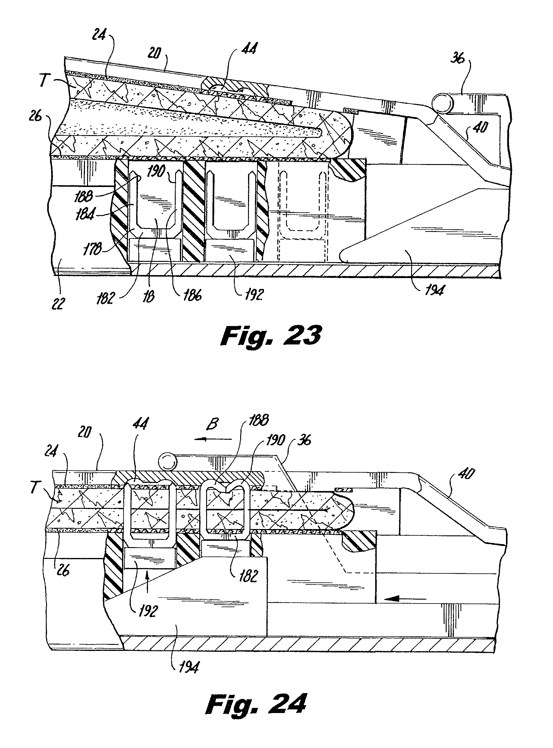
FIG. 23 is side view, partially shown in section, of the distal end of the surgical stapling instrument positioned about the tissue section;
FIG. 24 is a side view, partially shown in section, during initial actuation of the surgical stapling instrument of FIG. 1;
FIG. 25 is a perspective view of a stapled and divided tissue section; and
FIG. 26 is a cross-sectional view taken along line 26-26 of FIG. 25.
DETAILED DESCRIPTION OF EMBODIMENTS
Embodiments of the presently disclosed interlocking buttress material retention systems for use with surgical stapling instruments will now be described in detail with reference to the drawings wherein like numerals designate identical or corresponding elements in each of the several views. As is common in the art, the tell "proximal" refers to that part or component closer to the user or operator, i.e. surgeon or physician, while the term "distal" refers to that part or component further away from the user.
Referring now to FIG. 1, there is disclosed a linear surgical stapling instrument or surgical stapler 10 for use in stapling tissue and applying layers of buttress material between the staples and underlying tissue. An exemplary example of this type of surgical stapling instrument is disclosed in U.S. Pat. No. 7,128,253, the entire disclosure of which is incorporated by reference herein. Surgical stapler 10 generally includes a handle 12 having an elongate tubular member 14 extending distally from handle 12. A jaw assembly 16 is mounted on a distal end 18 of elongate tubular member 14. Jaw assembly 16 includes a staple clinching anvil 20 and a staple containing cartridge or staple cartridge 22. Staple cartridge 22 may be permanently affixed to elongate tubular member 14 or may be detachable and thus replaceable with a new staple cartridge 22. Staple clinching anvil 20 is movably mounted on distal end 18 of elongate tubular member 14 and is movable between an open position spaced apart from staple cartridge 22 to a closed position substantially adjacent staple cartridge 22.
Staple clinching anvil 20 is provided with a layer of anvil buttress material 24 and staple cartridge 22 is provided with a layer of cartridge buttress material 26 in the manners described in more detail hereinbelow. An anvil buttress retention system 28 is incorporated into anvil 20 and anvil buttress material 24 and is provided to releasably secure anvil buttress material 24 to staple clinching anvil 20. Likewise, a cartridge buttress retention system 30 incorporated into staple cartridge 22 and cartridge buttress material 26 and is provided to releasably secure cartridge buttress material 26 to staple cartridge 22. Anvil buttress material 24 and cartridge buttress material 26 are provided to reinforce and seal staple lines applied to tissue by surgical stapler 10.
Anvil buttress retention system 28 and cartridge buttress retention system 30 are particularly configured to allow the respective buttress materials to be localized on inwardly facing surfaces of anvil 20 and staple cartridge 22 in order to facilitate passage of surgical stapler 10 into the body of a patient without risk of tearing or wrinkling of the respective buttress materials as surgical stapler 10 is inserted into and manipulated within the body of a patient.
Surgical stapler 10 further includes a trigger 32 movably mounted on handle 12. Actuation of trigger 32 initially operates to move anvil 20 from the open to the closed position relative to staple cartridge 22 and subsequently actuate surgical stapler 10 to apply lines of staples to tissue. In order to properly orient jaw assembly 16 relative to the tissue to be stapled, surgical stapler 10 is additionally provided with a rotation knob 34 mounted on handle 12. Rotation of rotation knob 34 relative to handle 12 rotates elongate tubular member 14 and jaw assembly 16 relative to handle 12 so as to properly orient jaw assembly 16 relative to the tissue to be stapled.
Referring to FIGS. 1 and. 2, a driver 36 is provided to move anvil 20 between the open and closed positions relative to staple cartridge 22. Driver 36 moves between a longitudinal slot 38 formed in anvil 20. A knife blade (not shown) is associated with driver 32 to cut tissue captured between anvil 20 and staple cartridge 22 as driver 36 passes through slot 38.
Referring to FIG. 3, in order to move anvil 20 between the open and closed positions, anvil 20 includes a proximal, angled or sloped edge 40 configured to be engaged by driver 36 in order to cam anvil 20 to the closed position. Slot 38 extends distally from sloped edge 40 and terminates in a transverse slot 42 which is configured to capture driver 36 upon complete actuation of surgical stapler 10 to prevent any further actuation of surgical stapler 10. In order to secure staples provided by staple cartridge 22 about the tissues and buttress materials, anvil 20 is provided with longitudinally extending rows of staple clinching pockets 44 located on either side of longitudinal slot 38.
Referring still to FIG. 3, anvil buttress retention system 28, incorporated into anvil 20 and anvil buttress material 24, will now be described. Anvil buttress material 24, as well as cartridge buttress material 26. The buttress material for the staple cartridge 22 and/or anvil 20 may be made from any biocompatible natural or synthetic material. The material from which the buttress material is formed may be bioabsorbable or non-bioabsorbable. It should of course be understood that any combination of natural, synthetic, bioabsorbable and non-bioabsorbable materials may be used to form the buttress material.
Some non-limiting examples of materials from which the buttress material may be made include but are not limited to poly(lactic acid), poly (glycolic acid), poly (hydroxybutyrate), poly (phosphazine), polyesters, polyethylene glycols, polyethylene oxides, polyacrylamides, polyhydroxyethylmethylacrylate, polyvinylpyrrolidone, polyvinyl alcohols, polyacrylic acid, polyacetate, polycaprolactone, polypropylene, aliphatic polyesters, glycerols, poly(amino acids), copoly (ether-esters), polyalkylene oxalates, polyamides, poly (iminocarbonates), polyalkylene oxalates, polyoxaesters, polyorthoesters, polyphosphazenes and copolymers, block copolymers, homopolymers, blends and combinations thereof.
In embodiments, natural biological polymers are used in forming the buttress material. Suitable natural biological polymers include, but are not limited to, collagen, gelatin, fibrin, fibrinogen, elastin, keratin, albumin, hydroxyethyl cellulose, cellulose, hydroxypropyl cellulose, carboxyethyl cellulose, chitan, chitosan, and combinations thereof. In addition, the natural biological polymers may be combined with any of the other polymeric materials described herein to produce the buttress material.
The buttress material may be porous or non-porous, or combinations of porous and non-porous layers. Where the buttress material is non-porous, buttress material may retard or prevent tissue ingrowth from surrounding tissues thereby acting as an adhesion barrier and preventing the formation of unwanted scar tissue. Thus, in embodiments, the buttress material possesses anti-adhesion properties. Techniques for forming non-porous layers from such materials are within the purview of those skilled in the art and include, for example, casting, molding and the like.
In embodiments, the buttress material is porous and possesses hemostatic properties. Where the buttress material is porous, it has openings or pores over at least a portion of a surface thereof. Suitable materials for forming the porous layer include, but are not limited to foams (e.g., open or closed cell foams). In embodiments, the pores may be in sufficient number and size so as to interconnect across the entire thickness of the porous layer. In other embodiments, the pores do not interconnect across the entire thickness of the porous layer. In yet other embodiments, the pores do not extend across the entire thickness of the porous layer, but rather are present at a portion of the surface thereof. In embodiments, the openings or pores are located on a portion of the surface of the porous layer, with other portions of the porous layer having a non-porous texture. Those skilled in the art reading the present disclosure will envision other pore distribution patterns and configurations for the porous layer.
Where the buttress material is porous, the pores may be formed using any method suitable to forming a foam or sponge including, but not limited to the lyophilization or freeze-drying of a composition. Suitable techniques for making foams are within the purview of those skilled in the art. Porous buttress materials can be at least 0.2 cm thick, in embodiments from about 0.3 to about 1.5 cm thick. Porous buttress materials can have a density of not more than about 75 mg/cm.sup.2 and, in embodiments below about 20 mg/cm.sup.2. The size of the pores in the porous buttress materials can be from about 20 .mu.m to about 300 .mu.m, in embodiments from about 100 .mu.m to about 200 .mu.m.
The buttress material may also include a reinforcement member. The reinforcement member may be associated with a porous or non-porous layer or may be positioned between a non-porous layer and a porous layer of the buttress material. Alternatively, the reinforcement member may be positioned entirely within one or more of the individual layers (i.e., embedded within the porous layer, the non-porous layer, or both) of the buttress material. It is also envisioned that the reinforcement member may be positioned at the surface of one of the layers making up the buttress material and, in embodiments, may be positioned at an exterior surface of the buttress material.
Some suitable non-limiting examples of reinforcement members include fabrics, meshes, monofilaments, multifilament braids, chopped fibers (sometimes referred to in the art as staple fibers) and combinations thereof. Where the reinforcement member is a mesh, it may be prepared using any technique known to those skilled in the art, such as knitting, weaving, tatting, knipling or the like. Where monofilaments or multifilament braids are used as the reinforcement member, the monofilaments or multifilament braids may be oriented in any desired manner. For example, the monofilaments or multifilament braids may be randomly positioned with respect to each other within the buttress material. As another example, the monofilaments or multifilament braids may be oriented in a common direction within the buttress material. Where chopped fibers are used as the reinforcement member, the chopped fibers may be oriented in any desired manner. For example, the chopped fibers may be randomly oriented or may be oriented in a common direction. The chopped fibers can thus form a non-woven material, such as a mat or a felt. The chopped fibers may be joined together (e.g., by heat fusing) or they may be unattached to each other. The chopped fibers may be of any suitable length. For example, the chopped may be from 0.1 mm to 100 mm in length, in embodiments, 0.4 mm to 50 mm in length. In an illustrative embodiment, the buttress material has randomly oriented chopped fibers that have not been previously fused together embedded within in the buttress material.
It is envisioned that the reinforcement member may be formed from any bioabsorbable, non-bioabsorbable, natural, or synthetic material previously described herein and combinations thereof. Where monofilaments or multifilament braids are used as the reinforcement member, any commercially available suture material may advantageously be employed as the reinforcement member.
In embodiments, at least one bioactive agent may be combined with the buttress material and/or any of the individual components (the porous layer, the non-porous layer and/or the reinforcement member) used to construct the buttress material. In these embodiments, the buttress material can also serve as a vehicle for delivery of the bioactive agent. The team "bioactive agent", as used herein, is used in its broadest sense and includes any substance or mixture of substances that have clinical use. Consequently, bioactive agents may or may not have pharmacological activity per se, e.g., a dye, or fragrance. Alternatively a bioactive agent could be any agent which provides a therapeutic or prophylactic effect, a compound that affects or participates in tissue growth, cell growth, cell differentiation, an anti-adhesive compound, a compound that may be able to invoke a biological action such as an immune response, or could play any other role in one or more biological processes.
Examples of classes of bioactive agents which may be utilized in accordance with the present disclosure include anti-adhesives, antimicrobials, analgesics, antipyretics, anesthetics, antiepileptics, antihistamines, anti-inflammatories, cardiovascular drugs, diagnostic agents, sympathomimetics, cholinomimetics, antimuscarinics, antispasmodics, hormones, growth factors, muscle relaxants, adrenergic neuron blockers, antineoplastics, immunogenic agents, immunosuppressants, gastrointestinal drugs, diuretics, steroids, lipids, lipopolysaccharides, polysaccharides, and enzymes. It is also intended that combinations of bioactive agents may be used.
Anti-adhesive or anti-adhesion agents can be used to prevent adhesions from forming between the buttress material and the surrounding tissues opposite the target tissue. Some examples of these agents include, but are not limited to poly(vinyl pyrrolidone), carboxymethyl cellulose, hyaluronic acid, polyethylene oxide, poly vinyl alcohols and combinations thereof
Suitable antimicrobial agents which may be included as a bioactive agent in the buttress material of the present disclosure include triclosan, also known as 2,4,4'-trichloro-2'-hydroxydiphenyl ether, chlorhexidine and its salts, including chlorhexidine acetate, chlorhexidine gluconate, chlorhexidine hydrochloride, and chlorhexidine sulfate, silver and its salts, including silver acetate, silver benzoate, silver carbonate, silver citrate, silver iodate, silver iodide, silver lactate, silver laurate, silver nitrate, silver oxide, silver palmitate, silver protein, and silver sulfadiazine, polymyxin, tetracycline, aminoglycosides, such as tobramycin and gentamicin, rifampicin, bacitracin, neomycin, chloramphenicol, miconazole, quinolones such as oxolinic acid, norfloxacin, nalidixic acid, pefloxacin, enoxacin and ciprofloxacin, penicillins such as oxacillin and pipracil, nonoxynol 9, fusidic acid, cephalosporins, and combinations thereof In addition, antimicrobial proteins and peptides such as bovine lactoferrin and lactoferricin B may be included as a bioactive agent in the bioactive coating of the present disclosure.
Other bioactive agents which may be included as a bioactive agent in the buttress material in accordance with the present disclosure include: local anesthetics; non-steroidal antifertility agents; parasympathomimetic agents; psychotherapeutic agents; tranquilizers; decongestants; sedative hypnotics; steroids; sulfonamides; sympathomimetic agents; vaccines; vitamins; antimalarials; anti-migraine agents; anti-parkinson agents such as L-dopa; anti-spasmodics; anticholinergic agents (e.g. oxybutynin); antitussives; bronchodilators; cardiovascular agents such as coronary vasodilators and nitroglycerin; alkaloids; analgesics; narcotics such as codeine, dihydrocodeinone, meperidine, morphine and the like; non-narcotics such as salicylates, aspirin, acetaminophen, d-propoxyphene and the like; opioid receptor antagonists, such as naltrexone and naloxone; anti-cancer agents; anti-convulsants; anti-emetics; antihistamines; anti-inflammatory agents such as hormonal agents, hydrocortisone, prednisolone, prednisone, non-hormonal agents, allopurinol, indomethacin, phenylbutazone and the like; prostaglandins and cytotoxic drugs; estrogens; antibacterials; antibiotics; anti-fungals; anti-virals; anticoagulants; anticonvulsants; antidepressants; antihistamines; and immunological agents.
Other examples of suitable bioactive agents which may be included in the coating composition include viruses and cells, peptides, polypeptides and proteins, analogs, muteins, and active fragments thereof, such as immunoglobulins, antibodies, cytokines (e.g. lymphokines, monokines, chemokines), blood clotting factors, hemopoietic factors, interleukins (IL-2, IL-3, IL-4, IL-6), interferons (.beta.-IFN, (.alpha.-IFN and .gamma.-IFN), erythropoietin, nucleases, tumor necrosis factor, colony stimulating factors (e.g., GCSF, GM-CSF, MCSF), insulin, anti-tumor agents and tumor suppressors, blood proteins, gonadotropins (e.g., FSH, LH, CG, etc.), hormones and hormone analogs (e.g., growth hormone), vaccines (e.g., tumoral, bacterial and viral antigens); somatostatin; antigens; blood coagulation factors; growth factors (e.g., nerve growth factor, insulin-like growth factor); protein inhibitors, protein antagonists, and protein agonists; nucleic acids, such as antisense molecules, DNA and RNA; oligonucleotides; polynucleotides; and ribozymes.
Anvil buttress retention system 28 is provided to releasably secure anvil buttress material 24 to anvil 20 prior to stapling to tissue. Anvil buttress retention system 28 includes a distally raised region 46 formed on an undersurface 48 of anvil 20. As best shown in FIGS. 3 and 5, distally raised region 46 includes a pair of proximally extending fingers or projections 50 and 52 configured to releasably secure a distal end of anvil buttress material 24 on anvil 20. As used herein, the term "projections" refer to those structures provided on the jaws of the instrument which resemble fingers and are configured to engage buttress material positioned between the fingers in friction fit fashion. Projections 50 and 52 include respective necks 54, 56 and bulbous portions 58, 60 extending proximally from necks 54 and 56. Cut outs 62 and 64 are provided in a distal end 66 of anvil 20 for engagement with projections 50 and 52 of anvil 20. Cut outs 62 and 64 are configured with respective necks 68, 70 and bulbous portions 72 and 74 corresponding to necks 54, 56 and bulbous portions 58, 60 of anvil 20. Projections 50 and 52 along with cutouts 62 and 64 form pairs of interlocking fingers to hold anvil buttress material 24 on anvil 20.
Anvil buttress system 28 further includes a post 76 formed at a proximal end 78 of anvil 20. Anvil buttress material 24 is provided with a hole 80 at a proximal end 82 which is configured to engage post 76 and maintain anvil buttress material 24 taut across undersurface 48 of anvil 20.
As best shown in FIG. 3-6, post 76 is split into post halves 76a and 76b defining a channel 84 therebetween. Channel 84 corresponds to slot 38 in anvil 20 and allows for movement of driver 36, as well as the knife associated with driver 36, through slot 38 to close anvil 20 and cut anvil buttress material 24 in half after stapling.
Referring back for the moment to FIGS. 3 and 4, in order to assemble anvil buttress material 24 to anvil 20 using anvil buttress retention system 28, cut outs 62 and 64 at distal end 66 of anvil buttress material 24 are positioned over projections 50 and 52 on distally raised region 46 of anvil 20. Thereafter, anvil buttress material 24 is drawn taut proximally and hole 80 is positioned over post 76 at proximal end 78 of anvil 20 to secure anvil buttress material 24 against undersurface 48 of anvil 20.
Referring to FIGS. 7 and 8, there is disclosed an alternative embodiment of a retention system 86 for securing proximal end 82 of anvil buttress material 24 to anvil 20 in a manner to allow passage of driver 36 through slot 38 in anvil 20. Retention system 86 includes a mushroom shaped post or protrusion 88 having an enlarged cap 90 for placement through hole 80 in anvil buttress material 24. Cap 90 defines an underside surface or flange 92 configured to engage anvil buttress material 24. Similar to post 76 described hereinabove, protrusion 88 is split into protrusion halves 88a and 88b defining a slot 94 therebetween for passage of driver 36 and an associated knife blade. Cap 90 assists in preventing premature release of proximal end 82 of anvil buttress material 24. While not specifically shown, the area around hole 80 may include a perforated area to facilitate separation of anvil buttress material 24 from protrusion 88.
Referring to FIGS. 9 and 10, there is illustrated a further alternative embodiment of a retention system 94 for retaining proximal end 82 of anvil buttress material 24 on anvil 20. Anvil 20 is provided with a pair of horizontally spaced apart posts 96 and 98 positioned on either side of slot 38. Proximal end 82 of anvil buttress material 24 is provided with a pair of corresponding holes 100 and 102 configured to be engaged by posts 96 and 98, respectively. Posts 96 and 98 locate the area securing anvil buttress material 24 outwardly of slot 38 in anvil 20. This assists in maintaining outer edges 104 and 106 of anvil buttress material 24 taut during use of surgical stapler 10.
Referring now to FIGS. 11 and 12, cartridge buttress retention system 30 will now be described. As noted hereinabove, cartridge buttress retention system 30 is provided to retain cartridge buttress material 26 on staple cartridge 22 prior to stapling of tissue. Staple cartridge 22 generally includes a U-shaped outer channel 108 surrounding a staple containing insert 110. Staple containing insert 110 is provided with rows of staple pockets 112, the function of which is described in more detail hereinbelow. A knife channel 114 passes longitudinally through staple containing insert 110 between rows of staple pockets 12.
Referring for the moment to FIGS. 11 and 15, cartridge buttress retention system 30 includes a post 116 formed at a distal end 118 of staple containing insert 110. Post 116 is similar to post 76 described hereinabove and is split into halves 116a and 116b to accommodate the passage of a knife blade to sever tissue and cartridge buttress material 26. Cartridge buttress material 26 includes a corresponding hole 20 formed in a distal end 122 of cartridge buttress material and configured to fit over post 116 on staple containing insert 110.
Referring back to FIGS. 11 and 12, and with regard to FIG. 13, cartridge buttress retention system 30 further includes a pair of distally extending and relatively straight, spaced apart fingers or projections 124 and 126 formed in a proximal end 128 of staple containing insert 110. Projections 124 and 126 are positioned on either side of knife channel 114 to secure cartridge buttress material 26 adjacent outer edges 130 and 132 of cartridge buttress material 26. Cartridge buttress material 26 is provided with corresponding slots 134 and 136 formed in a proximal end 138 of cartridge buttress material 26. Slots 134 and 136 are configured to engage projections 124 and 126 of staple containing insert 110 in friction fit fashion to retain proximal end 138 of cartridge buttress material 26 on proximal end 128 of staple containing insert 110.
In order to assemble cartridge buttress retention system 30, hole 120 in cartridge buttress material 26 is positioned over protrusion 116 on distal end 118 of staple containing insert 110. Thereafter, proximal end 138 of cartridge buttress material 26 is positioned over proximal end 128 of staple containing insert 110. Slots 134 and 136 in anvil buttress material 26 are forced over projections 124 and 126 on staple containing insert 110 to engage anvil buttress material 26 with staple containing inset 110 in friction fit fashion.
Referring for the moment to FIG. 14, in an alternative embodiment, proximal end 128 of staple containing insert 110 is provided with multiple sets of fingers or projections 140, 142 and 144, 146 positioned on either side of knife channel 114. Projections 140, 142 and 144, 146 engage corresponding sets of slots 148, 150 and 152, 154, respectively, to secure proximal end 138 of cartridge buttress material 26 to proximal end 128 of staple containing insert 110. By providing multiple sets of fingers on the jaw and corresponding slots in the buttress material, the surface area available for frictional contact is increased providing a more secure connection. While not specifically shown, more than two sets of fingers and slots may be provided depending on the nature of the buttress material and amount of frictional contact required.
Referring now to FIGS. 16-21, and initially with regard to FIGS. 16 and 17, alternative methods of releasably securing buttress material to a jaw of a surgical instrument will now be described. A split protrusion 156, similar to protrusion 88 described hereinabove, is formed on a distal end 118 of staple containing insert 110 and includes cap halves 158a and 158b defining flanges 160a and 160b. Hole 120 in distal end 122 of cartridge buttress material 26 fits over split protrusion 156 to secure distal end 122 of cartridge buttress material 26 to distal end 118 of staple containing insert 110.
Referring to FIGS. 18 and 19, distal ends 118 and 120 of staple containing insert 110 and cartridge buttress material 26 may be provided with spaced apart posts 162,164 and spaced apart holes 166, 168, respectively. Posts 162, 164 and holes 166, 168 function substantially identically to posts 96, 98 and holes 100, 102, described hereinabove, to secure distal end 122 of cartridge buttress material 26 to distal end 118 of staple containing insert 110.
With respect to FIGS. 20 and 21, a solid, unsplit post 170 is provided on distal end 118 of staple containing insert 110. Post 170 is located distally of a distal end 172 of knife channel 114. A hole 174 is provided in distal end 120 of cartridge buttress material 26 and a longitudinal slit 176 is formed through the area defining hole 174. In use, a knife associated with surgical stapler 10 cuts through cartridge buttress material 26 through the length of knife channel 114. After cartridge buttress material 26 has been stapled to tissue and almost completely been cut in half, longitudinal slit 176 allows cartridge buttress material 26 to separate in half without tearing or snagging.
Referring now to FIGS. 22 through 26, and initially with respect to FIGS. 22 and 23, the use of surgical stapler 10 to staple and divide a tubular tissue section T will now be described. Initially, jaw assembly 16, including anvil 20 and staple containing cartridge 22 are positioned around the tissue T to be stapled. Driver 36 is in a proximal position relative to anvil slot 38. As best shown in FIG. 23, staple containing insert 110 includes staples 178 positioned within individual staple pockets 180 of row of staple pockets 112. Staples 178 are of a conventional type and include a backspan 182 having a pair of legs 184 and 186 extending from backspan 182. Legs 184 and 186 terminate in tissue penetrating tips 188 and 190. Pushers 192 are located within staple pockets 180 and are positioned between staples 178 and the path of a drive bar 194.
Referring now to FIG. 24, surgical stapler 10 is initially actuated by movement of trigger 32 relative to handle 12 (FIG. 1) causing driver 36 to move in the direction of arrow B and against sloped edge 40 of anvil 20 thereby causing anvil 20 to be moved to the closed position relative to staple cartridge 22. As drive bar 194 advances distally within staple containing insert 110, drive bar 194 urges pushers 192 upwardly against backspans 182 of staples 178 driving staples 178 through cartridge buttress material 26, tissue T, anvil buttress material 24 and towards staple clinching pockets 44 in anvil 20. Tissue penetrating tips 188 and 190 are bent within staple clinching pockets 44 in anvil 20 to thereby secure anvil buttress material 24 against tissue T while backspan 182 secures cartridge buttress material 26 against tissue T.
While not specifically shown, upon full actuation of surgical stapler 10, a knife blade associated with surgical stapler 10 and carried by driver 36 cuts tissue T, as well as anvil buttress material 24 and cartridge buttress material 26 between the rows of now clinched staples 102. Upon movement of anvil 20 to the open position spaced apart from staple cartridge 22, anvil buttress material 24 pulls away from anvil 20 and cartridge buttress material 26 pulls away from staple cartridge 22. Specifically, distal end 122 of cartridge buttress material 26 is cut through by the knife and is released from post 116. Proximal end 138 of cartridge buttress material 26 pulls free from longitudinal projections 124, 126 at proximal end 128 of staple containing insert 110. Likewise, distal end 66 of anvil buttress material 24 pulls free from proximally extending projections 50, 52 and proximal end 82 of anvil buttress material 24 pulls free from post 78.
The resulting tissue T, divided and stapled closed with staples 178, is best illustrated in FIGS. 25 and 26. Specifically, cartridge buttress material 26 is secured against tissue T by backspans 182 of staples 178 and anvil buttress material 24 is secured against tissue T by the now clinched tissue penetrating tips 188 and 190 of staples 178. In this manner, anvil buttress material 24 and cartridge buttress material 26 are stapled to tissue T thereby sealing and reinforcing these staple lines created by staples 178.
It will be understood that various modifications may be made to the embodiments disclosed herein. For example, various numbers of interlocking fingers or projections may be provided to increase the frictional contact between a jaw and an associated buttress material. Further, the disclosed buttress materials may be provided with various perforated regions to facilitate release from the disclosed fingers or projections and posts. Therefore, the above description should not be construed as limiting, but merely as exemplifications of particular embodiments. Those skilled in the art will envision other modifications within the scope and spirit of the claims appended hereto.
* * * * *
D00000
D00001
D00002
D00003
D00004
D00005
D00006
D00007
D00008
XML
uspto.report is an independent third-party trademark research tool that is not affiliated, endorsed, or sponsored by the United States Patent and Trademark Office (USPTO) or any other governmental organization. The information provided by uspto.report is based on publicly available data at the time of writing and is intended for informational purposes only.
While we strive to provide accurate and up-to-date information, we do not guarantee the accuracy, completeness, reliability, or suitability of the information displayed on this site. The use of this site is at your own risk. Any reliance you place on such information is therefore strictly at your own risk.
All official trademark data, including owner information, should be verified by visiting the official USPTO website at www.uspto.gov. This site is not intended to replace professional legal advice and should not be used as a substitute for consulting with a legal professional who is knowledgeable about trademark law.