Conforming back for a seating unit
Peterson , et al. October 6, 2
U.S. patent number 10,791,842 [Application Number 15/488,372] was granted by the patent office on 2020-10-06 for conforming back for a seating unit. This patent grant is currently assigned to Steelcase Inc.. The grantee listed for this patent is Steelcase Inc.. Invention is credited to Russell Holdredge, Kara Johnson, Christopher J. Norman, Thomas Overthun, Luke Pearson, Gordon J. Peterson, Bruce Smith.


View All Diagrams
| United States Patent | 10,791,842 |
| Peterson , et al. | October 6, 2020 |
Conforming back for a seating unit
Abstract
According to the present invention a back for a seating unit is provided. The back comprises a plurality of flexible finger elements. Each of the plurality of flexible finger elements has a distal end. The back further comprises a retainer connecting at least two of the flexible finger elements proximate their distal ends. When a load is applied to a flexible finger element, the retainer distributes at least a portion of the load to at least one adjacent flexible finger element.
| Inventors: | Peterson; Gordon J. (Rockford, MI), Norman; Christopher J. (Byron Center, MI), Holdredge; Russell (Alto, MI), Smith; Bruce (Grand Rapids, MI), Pearson; Luke (London, GB), Overthun; Thomas (San Francisco, CA), Johnson; Kara (San Francisco, CA) | ||||||||||
|---|---|---|---|---|---|---|---|---|---|---|---|
| Applicant: |
|
||||||||||
| Assignee: | Steelcase Inc. (Grand Rapids,
MI) |
||||||||||
| Family ID: | 1000005094171 | ||||||||||
| Appl. No.: | 15/488,372 | ||||||||||
| Filed: | April 14, 2017 |
Prior Publication Data
| Document Identifier | Publication Date | |
|---|---|---|
| US 20170224119 A1 | Aug 10, 2017 | |
Related U.S. Patent Documents
| Application Number | Filing Date | Patent Number | Issue Date | ||
|---|---|---|---|---|---|
| 14515097 | Oct 15, 2014 | 9648956 | |||
| 12454995 | Nov 4, 2014 | 8876209 | |||
| 61056051 | May 26, 2008 | ||||
| Current U.S. Class: | 1/1 |
| Current CPC Class: | A47C 7/405 (20130101); A47C 3/00 (20130101); A47C 7/445 (20130101); A47C 3/12 (20130101); A47C 7/44 (20130101) |
| Current International Class: | A47C 7/44 (20060101); A47C 3/12 (20060101); A47C 7/40 (20060101); A47C 3/00 (20060101) |
References Cited [Referenced By]
U.S. Patent Documents
| 190967 | May 1877 | Hess |
| D12144 | February 1881 | Blent |
| 242633 | June 1881 | Guerrent |
| 293833 | February 1884 | Winchester |
| 398179 | February 1889 | Parry |
| 538708 | May 1895 | Smith |
| 2016953 | October 1935 | Arnold |
| 2182485 | December 1939 | Murdock |
| 2365334 | December 1944 | De Vries |
| 2530924 | November 1950 | Turner |
| D164204 | August 1951 | Smith |
| 2648372 | August 1953 | Smith |
| 2649147 | August 1953 | Sanford |
| 2798538 | July 1957 | Dreifke |
| 2817390 | December 1957 | Crites |
| 2843195 | July 1958 | Barvaeus |
| 2893476 | July 1959 | Liljengren |
| 2894565 | July 1959 | Conner |
| D194740 | March 1963 | Parker |
| 3106423 | October 1963 | Schwarz |
| D197512 | February 1964 | Poisson |
| 3135552 | June 1964 | Lackshin |
| 3135553 | June 1964 | Lockshin |
| 3203734 | August 1965 | Seymer |
| D212470 | October 1968 | Rutter |
| 3565482 | February 1971 | Blodee |
| 3669499 | June 1972 | Semplonius et al. |
| 3731342 | May 1973 | Cousin |
| 3752533 | August 1973 | Gilbert |
| 3813148 | May 1974 | Kraus |
| 3877750 | April 1975 | Scholpp |
| 3948558 | April 1976 | Obermeier et al. |
| 3982785 | September 1976 | Ambasz |
| 3989297 | November 1976 | Kerstholt |
| 4007962 | February 1977 | Muller-Deisig |
| 4054318 | October 1977 | Costlin |
| 4062590 | December 1977 | Polsky et al. |
| 4084850 | April 1978 | Ambasz |
| 4157203 | June 1979 | Ambasz |
| 4314728 | February 1982 | Faiks |
| 4316632 | February 1982 | Brauning |
| 4333683 | June 1982 | Ambasz |
| 4380352 | April 1983 | Diffrient |
| 4498702 | February 1985 | Raftery |
| 4502728 | March 1985 | Sheldon |
| 4521053 | June 1985 | De Boer |
| 4544204 | October 1985 | Schmale |
| 4585272 | April 1986 | Ballarini |
| 4621866 | November 1986 | Zani et al. |
| 4641884 | February 1987 | Miyashita et al. |
| 4660887 | April 1987 | Fleming et al. |
| 4685730 | August 1987 | Linguanotto |
| 4703974 | November 1987 | Brauning |
| 4744603 | May 1988 | Knoblock |
| 4776633 | October 1988 | Knoblock et al. |
| 4810033 | March 1989 | Kernmann |
| 4834453 | May 1989 | Makiol |
| 4848837 | July 1989 | Volkle |
| 4861108 | August 1989 | Acton et al. |
| 4896918 | January 1990 | Hoshihara |
| 4928334 | May 1990 | Kita |
| 4962964 | October 1990 | Snodgrass |
| 4966413 | October 1990 | Palarski |
| 4968093 | November 1990 | Dal Monte |
| 4981326 | January 1991 | Heidmann |
| 5009466 | April 1991 | Perry |
| 5015034 | May 1991 | Kindig et al. |
| 5015038 | May 1991 | Mrotz, III |
| D319354 | August 1991 | Wolcott |
| 5039163 | August 1991 | Tolleson |
| 5040847 | August 1991 | Nguyen |
| 5044693 | September 1991 | Yokota |
| 5050930 | September 1991 | Schuster et al. |
| 5050931 | September 1991 | Knoblock |
| 5062676 | November 1991 | Mars |
| 5087098 | February 1992 | Ishizuka |
| 5100201 | March 1992 | Becker, III et al. |
| 5102196 | April 1992 | Kaneda et al. |
| 5112108 | May 1992 | Zapf |
| 5120109 | June 1992 | Rangoni |
| 5121963 | June 1992 | Kwasnik et al. |
| D330292 | October 1992 | Nguyen |
| 5154485 | October 1992 | Fleishman |
| D332530 | January 1993 | Nguyen |
| 5217278 | June 1993 | Harrison et al. |
| 5240308 | August 1993 | Goldstein |
| 5249839 | October 1993 | Faiks et al. |
| D341265 | November 1993 | Gehry |
| 5277475 | January 1994 | Brandes |
| D344191 | February 1994 | Gehry |
| D345656 | April 1994 | Theobald |
| 5299851 | April 1994 | Lin |
| 5302002 | April 1994 | Nagasaka |
| 5320410 | June 1994 | Faiks et al. |
| 5333934 | August 1994 | Knoblock |
| 5338091 | August 1994 | Miller |
| 5338094 | August 1994 | Perry |
| 5352022 | October 1994 | Knoblock |
| 5354120 | October 1994 | Volkle |
| 5366273 | November 1994 | Bresch |
| D354405 | January 1995 | Greene |
| 5380063 | January 1995 | Dauphin |
| 5385388 | January 1995 | Faiks et al. |
| 5405188 | April 1995 | Hanson |
| D360538 | July 1995 | Skalka |
| 5447356 | September 1995 | Snijders |
| 5460427 | October 1995 | Serber |
| D363844 | November 1995 | Maple et al. |
| 5474360 | December 1995 | Chang et al. |
| 5487591 | January 1996 | Knoblock |
| 5518294 | May 1996 | Ligon, Sr. et al. |
| 5540481 | July 1996 | Roossien et al. |
| 5573302 | November 1996 | Harrison et al. |
| 5575534 | November 1996 | Yu |
| 5577807 | November 1996 | Hodge et al. |
| 5577811 | November 1996 | Ogg |
| 5582459 | December 1996 | Hama et al. |
| 5590932 | January 1997 | Olivieri |
| 5597203 | January 1997 | Hubbard |
| 5611598 | March 1997 | Knoblock |
| 5630647 | May 1997 | Heidmann et al. |
| 5662383 | September 1997 | Hand |
| 5664835 | September 1997 | Desanta |
| D384511 | October 1997 | Gresens |
| 5683142 | November 1997 | Gunderson et al. |
| 5716099 | February 1998 | McDiarmid |
| 5762403 | February 1998 | McDiarmid |
| 5769500 | June 1998 | Holbrook |
| 5791736 | August 1998 | Herbert |
| 5810438 | September 1998 | Newhouse |
| 5863094 | January 1999 | Endo |
| 5871258 | February 1999 | Battey et al. |
| 5904397 | May 1999 | Fismen |
| 5938284 | August 1999 | Coffield |
| D413452 | September 1999 | Rhienen |
| D415626 | October 1999 | Van Rhienen |
| D417968 | December 1999 | Van Rhienen |
| D420522 | February 2000 | Rhienen |
| D420824 | February 2000 | Lin |
| 6019428 | February 2000 | Coffield |
| 6027171 | February 2000 | Partington et al. |
| 6059368 | May 2000 | Stumpf et al. |
| D430975 | September 2000 | Grosfillex |
| D431922 | October 2000 | Grosfillex |
| 6139110 | October 2000 | Jeng |
| 6164726 | December 2000 | Reeves et al. |
| D437134 | February 2001 | Anderson et al. |
| 6186594 | February 2001 | Valiquette et al. |
| 6231125 | May 2001 | Maeda et al. |
| D443430 | June 2001 | Anderson et al. |
| D456159 | April 2002 | Ball |
| 6378942 | April 2002 | Chu |
| 6378944 | April 2002 | Weisser |
| D456650 | May 2002 | Ball |
| D457023 | May 2002 | Ball |
| 6386634 | May 2002 | Stumpf et al. |
| 6386638 | May 2002 | Strauch |
| 6394548 | May 2002 | Battley et al. |
| 6409268 | June 2002 | Cvek |
| 6419318 | July 2002 | Albright |
| 6422650 | July 2002 | Chien-Shen |
| 6439665 | August 2002 | Cvek |
| 6499802 | December 2002 | Drira |
| 6511562 | January 2003 | Coffield |
| D469619 | February 2003 | Stewart |
| D470669 | February 2003 | Stewart |
| 6523898 | February 2003 | Ball et al. |
| 6540950 | April 2003 | Coffield |
| 6550866 | April 2003 | Su |
| 6669292 | December 2003 | Koepke et al. |
| 6669301 | December 2003 | Funk et al. |
| 6688687 | February 2004 | Chu |
| 6688690 | February 2004 | Watson et al. |
| 6698833 | March 2004 | Ball et al. |
| 6712427 | March 2004 | Bourdkane et al. |
| 6715839 | April 2004 | Legal |
| 6726286 | April 2004 | Stumpf et al. |
| 6755467 | June 2004 | Chu |
| 6758528 | July 2004 | Kawashima |
| 6811218 | November 2004 | Deimen et al. |
| 6842959 | January 2005 | Coffield et al. |
| 6890030 | May 2005 | Wilkerson et al. |
| 6899398 | May 2005 | Coffield |
| 6908159 | June 2005 | Prince et al. |
| D506893 | July 2005 | Hsien |
| 6913315 | July 2005 | Ball et al. |
| 6918633 | July 2005 | Forkel et al. |
| 6942300 | September 2005 | Numa et al. |
| 6955402 | October 2005 | VanDeRiet et al. |
| 6966606 | November 2005 | Coffield |
| 6969115 | November 2005 | Bourdkane et al. |
| 6971717 | December 2005 | Rhodes |
| 6983997 | January 2006 | Wilkerson et al. |
| 7032971 | April 2006 | Williams |
| 7096549 | August 2006 | Coffield |
| 7097247 | August 2006 | Battey et al. |
| 7128373 | October 2006 | Kurtycz et al. |
| 7131694 | November 2006 | Buffa |
| D535838 | January 2007 | Ritch et al. |
| 7159293 | January 2007 | Coffield et al. |
| 7216933 | May 2007 | Schmidt |
| D544720 | June 2007 | Berbegal Perez |
| 7249802 | July 2007 | Schmitz |
| D548475 | August 2007 | Ritch et al. |
| D550471 | September 2007 | Igarashi |
| 7270378 | September 2007 | Wilkerson et al. |
| D553376 | October 2007 | Nakamura |
| 7367629 | May 2008 | Kepler et al. |
| D575085 | August 2008 | Su |
| D575542 | August 2008 | Igarashi |
| D581689 | December 2008 | Marini |
| D587915 | March 2009 | Igarashi |
| D592876 | May 2009 | Smith et al. |
| D600052 | September 2009 | Smith et al. |
| D600931 | September 2009 | Pearson |
| D600949 | September 2009 | Overthun |
| 7604298 | October 2009 | Peterson et al. |
| 7611199 | November 2009 | Michalak |
| D615784 | May 2010 | Parker |
| D616213 | May 2010 | Parker |
| 7841664 | November 2010 | Holdredge et al. |
| 7841666 | November 2010 | Scmitz et al. |
| D638232 | May 2011 | Roy |
| D646085 | October 2011 | Overthun et al. |
| D650197 | December 2011 | Kang |
| 8075061 | December 2011 | Ko |
| D654291 | February 2012 | Pearson |
| D660056 | May 2012 | Diffrient |
| 8172332 | May 2012 | Masunaga |
| D661504 | June 2012 | Saotome |
| 8256845 | September 2012 | Wang |
| D676254 | February 2013 | Chen |
| D680765 | April 2013 | Ballendat |
| D696545 | December 2013 | Pearson |
| D696886 | January 2014 | Nakamura |
| 8876209 | November 2014 | Peterson et al. |
| D731833 | June 2015 | Fifield |
| D735513 | August 2015 | Chan |
| D767321 | September 2016 | Xingchang |
| 9596941 | March 2017 | Romero |
| 9648956 | May 2017 | Peterson et al. |
| D815868 | April 2018 | Romero |
| 9968199 | May 2018 | Romero |
| 2002/0043871 | April 2002 | Prince |
| 2002/0060492 | May 2002 | Nagamitsu |
| 2002/0140276 | October 2002 | Funk |
| 2002/0195863 | December 2002 | Su |
| 2004/0100139 | May 2004 | Williams |
| 2004/0124689 | July 2004 | Numa |
| 2004/0245840 | December 2004 | Tubergen |
| 2004/0262975 | December 2004 | Su |
| 2005/0093354 | May 2005 | Ball et al. |
| 2005/0200189 | September 2005 | Schultz et al. |
| 2006/0006715 | January 2006 | Chadwick et al. |
| 2007/0035169 | February 2007 | Sawyer |
| 2007/0057548 | March 2007 | Buffa |
| 2007/0057549 | March 2007 | Ball et al. |
| 2007/0228799 | October 2007 | Kinoshita et al. |
| 2007/0257531 | November 2007 | Mashimo |
| 2007/0267912 | November 2007 | Britton |
| 2008/0122284 | May 2008 | Yang |
| 2008/0122285 | May 2008 | Lin |
| 2009/0127914 | May 2009 | Igarashi |
| 2009/0140568 | June 2009 | Chan |
| 2010/0072799 | March 2010 | Peterson |
| 2013/0154314 | June 2013 | Romero |
| 2014/0077574 | March 2014 | Okuda |
| 2015/0091350 | April 2015 | Peterson et al. |
| 2015/0296989 | October 2015 | Machael |
| 2313750 | Dec 2001 | CA | |||
| 1822780 | Aug 2006 | CN | |||
| 19526437 | Jan 1997 | DE | |||
| 2130456 | Dec 2009 | EP | |||
| 2008080090 | Apr 2008 | JP | |||
| 2008080092 | Apr 2008 | JP | |||
| WO 1994/006339 | Mar 1994 | WO | |||
Other References
|
Chinese Office Action issued for CN201410380243.2 dated May 4, 2016 and English language translation. cited by applicant . Extended European Search Report and Preliminary Opinion, European Patent Application No. 09762841.6, dated Jul. 22, 2011. cited by applicant . Written Opinion and International Search Report issued in connection with PCT Patent Application No. PCT/US2009/003235 dated Jan. 19, 2010. cited by applicant. |
Primary Examiner: Walraed-Sullivan; Kyle J.
Attorney, Agent or Firm: Morgan, Lewis & Bockius LLP
Parent Case Text
CROSS REFERENCE TO RELATED APPLICATIONS
This application is a continuation of, and claims priority from, and incorporates the disclosure of U.S. patent application Ser. No. 14/515,097, filed Oct. 15, 2014, now U.S. Pat. No. 9,648,956, which is a continuation of U.S. patent application Ser. No. 12/454,995, filed May 26, 2009, now U.S. Pat. No. 8,876,209, which claims priority to U.S. Provisional Patent Application No. 61/056,051, filed May 26, 2008.
Claims
What is claimed is:
1. A flexible back for a seating unit, the flexible back having a lumbar region and a thoracic region, the flexible back configured for attachment to a seating unit having a seat and a frame, the frame comprising a first arm and a second arm, at least a portion of each of the first arm and the second arm being integrally formed with the frame, wherein the flexible back is positioned between the first arm and the second arm, and the flexible back is integrally formed with any one of the frame, the first arm and the second arm, and wherein the flexible back defines a plurality of discrete flexible zones disposed between the first and second arms, the flexibility of the plurality of discrete flexible zones of the flexible back being independent of the first and second arms, the flexible back comprising: a plurality of flexible finger elements, each of the plurality of flexible finger elements having a distal end and each of the plurality of flexible finger elements being formed of an elastomeric material and being adapted to be flexible independently of each of the other of the plurality flexible finger elements, wherein the distal end of at least one of the plurality of flexible finger elements is comprised of at least a first flexible prong and a second flexible prong, the first flexible prong being flexible independent of the second flexible prong; and a flexible retainer defining an uppermost and continuous edge of the flexible back connecting at least two of the flexible finger elements proximate the distal ends of the at least two of the plurality of flexible finger elements and limiting the independent flex of the at least two of the plurality of flexible finger elements.
2. The flexible back of claim 1, wherein when a load is applied to at least one flexible finger element, the at least one flexible finger element flexes a distance controlled by the flexible retainer.
3. The flexible back of claim 1, wherein the flexible retainer constrains movement of each of the flexible finger elements relative to an adjacent flexible finger element.
4. The flexible back of claim 1, wherein each of the plurality of flexible finger elements is disposed generally vertically relative to the generally horizontal seat.
5. The flexible back of claim 1, wherein the flexible retainer has a third flexibility, the third flexibility being greater than the second flexibility.
6. The flexible back of claim 1, wherein the flexible retainer is overmolded over the flexible finger elements.
7. The flexible back of claim 1, wherein each of the plurality of flexible finger elements is integrally formed with the flexible retainer.
8. A seating unit comprising: a seat; a frame coupled to the seat, the frame comprising a first arm and a second arm, at least a portion of each of the first arm and the second arm being integrally formed with the frame; a flexible back coupled to the seat, wherein the flexible back is not integrally formed with any one of the frame, the first arm and second arm, and wherein the flexibility of the flexible back is independent of the first and second arms, the flexible backcomprising: a plurality of flexible finger elements, each of the plurality of flexible finger elements having a distal end and each of the plurality of flexible finger elements being formed of an elastomeric material and being flexible independently of each of the other of the plurality flexible finger elements, wherein the distal end of at least one of the plurality of flexible finger elements is comprised of at least a first flexible prong and a second flexible prong, the first flexible prong being flexible independent of the second flexible prong; and a flexible retainer defining an uppermost and continuous edge of the flexible back connecting at least two of the flexible finger elements proximate the distal ends of the at least two flexible finger elements and limiting the independent flex of the at least two flexible finger elements.
9. The seating unit of claim 8, wherein when a load is applied to at least one flexible finger element, the at least one flexible finger element flexes a distance controlled by the flexible retainer.
10. The seating unit of claim 8, wherein the flexible retainer constrains movement of each of the flexible finger elements relative to an adjacent flexible finger element.
11. The seating unit of claim 8, wherein the flexible retainer has a third flexibility, the third flexibility being greater than the second flexibility.
12. The seating unit claim 8, wherein the flexible retainer is overmolded over the flexible finger elements.
13. The seating unit of claim 8, wherein each of the plurality of flexible finger elements is integrally formed with the flexible retainer.
14. The seating unit of claim 8, wherein each of the plurality of flexible finger elements has a first flexibility and the flexible retainer has a second flexibility.
15. A flexible back for a seating unit, the flexible back having a lumbar region and a thoracic region, the flexible back configured for attachment to a seating unit having a seat and a frame, the frame comprising a first arm and a second arm, at least a portion of each of the first arm and the second arm being integrally formed with the frame, wherein the flexible back is positioned between the first arm and the second arm, and the flexible back is integrally formed with any one of the frame, the first arm and the second arm, and wherein the flexible back defines a plurality of discrete flexible zones disposed between the first and second arms, the flexibility of the plurality of discrete flexible zones of the flexible back being independent of the first and second arms, the flexible back comprising: a plurality of flexible finger elements, each of the plurality of flexible finger elements having a distal end and each of the plurality of flexible finger elements being formed of an elastomeric material and being adapted to be flexible independently of each of the other of the plurality flexible finger elements, wherein the distal end of at least one flexible finger element is comprised of at least a first flexible prong and a second flexible prong, the first flexible prong being flexible independent of the second flexible prong; and a flexible retainer defining an uppermost and continuous edge of the flexible back connecting at least two of the flexible finger elements proximate the distal ends of the at least two of the plurality of flexible finger elements and limiting the independent flex of the at least two of the plurality of flexible finger elements.
16. The flexible back of claim 15, wherein the flexible retainer is coupled to the first and second flexible prongs.
Description
TECHNICAL FIELD
The present invention relates generally to a back for a seating unit, and more particularly, to back that conforms to the user.
BACKGROUND OF THE INVENTION
It is generally known to provide support for individuals sitting in a chair. It has been determined that certain shapes for chair backs provide increased support for individuals, thereby minimizing stress on the bodies of individuals, such as back stress, and providing a more comfortable sitting experience.
Comfort features that require little or no adjustment, particularly those directed to the back region, are in increasing demand in seating design. Prior designs have attempted to incorporate adjustment features in an effort to minimize stress on a user. For example, adjustments such as tilting backrests and slidable chair seats have been employed. Such mechanisms often require complex controls, linkages and other parts. Many chairs, such as collaborative seating, conference room seating, seating in team spaces and lobby seating, are utilized for relatively short periods of time or used by multiple people. Users typically will not take the time to make multiple adjustments on chairs used for a short period of time. When a user leaves the chair, it will generally be occupied by a new user. People come in various heights and sizes and any user adjustments to optimize comfort made by a first user are unlikely to be optimized for the next user. As a result task chairs with multiple adjustments tend not to be used in collaborative and short-term sitting applications. An alternative is a chair that is often used in short-term and collaborative environments with few or no adjustments. These chairs are sub-optimized for most users. It is desirable to provide a chair that self-adjusts to accommodate a variety of people or with minimal adjustment. Moreover, regular changes in body posture resulting from sitting for protracted periods pose unique problems in designing an ergonomic system not fully addressed by these designs. As such, many past chair solutions provide only monolithic solutions to wide ranging ergonomic needs. Thus, past designs have failed to provide adequate comfort to varying individuals that sit with disparate postures. It is, therefore, desirable to provide a chair back that conforms to the body, and in particular, on the lumbar and thoracic regions of the back of a variety of users sitting in disparate positions.
In lobbies and other public spaces it is desirable to keep a particular look or orientation to the furniture. Prior designs provide seating units with fixed orientation which a user is unlikely to move and which does not facilitate alternative postures or full utilization of the furniture. For example, two chairs set next to each other in a lobby orient their users parallel to each other. The users must rotate their bodies in order to look each other in the eye as they converse. It is desirable to have seats and/or backs which swivel to allow the user to orient himself relative to his or her task or other people. It is also desirable to have a chair which allows for alternative postures.
The present invention is provided to solve the problems discussed above and other problems, and to provide advantages and aspects not previously provided. A full discussion of the features and advantages of the present invention is deferred to the following detailed description, which proceeds with reference to the accompanying drawings.
SUMMARY OF THE INVENTION
According to the present invention a back for a seating unit is provided. The back comprises a plurality of flexible finger elements. Each of the plurality of flexible finger elements has a distal end. The back further comprises a retainer connecting at least two of the flexible finger elements proximate their distal ends. When a load is applied to a finger element, the retainer distributes at least a portion of the load to at least one adjacent flexible finger element.
According to another aspect of the invention, a comfort surface for a seating unit is provided. The comfort surface includes a plurality of flexible finger elements having distal ends. The comfort surface further comprises a retainer. The retainer connects at least two of the flexible finger elements proximate their distal ends. In use, the movement of the plurality of flexible finger elements and the retainer is cooperative.
According to another aspect of the invention, a seating unit is provided. The seating unit comprises a seat and a back which is adapted to be coupled to the seat. The back comprises a plurality of flexible finger elements and a retainer. The flexible finger elements have distal ends, and the retainer connects at least two of the flexible finger elements proximate their distal ends. The plurality of flexible finger elements and the retainer adapt to the shape of a user.
Other features and advantages of the invention will be apparent to those of skill in the art from the following specification and claims, taken in conjunction with the appended drawings.
BRIEF DESCRIPTION OF THE DRAWINGS
To understand the present invention, it will now be described by way of example, with reference to the accompanying drawings in which:
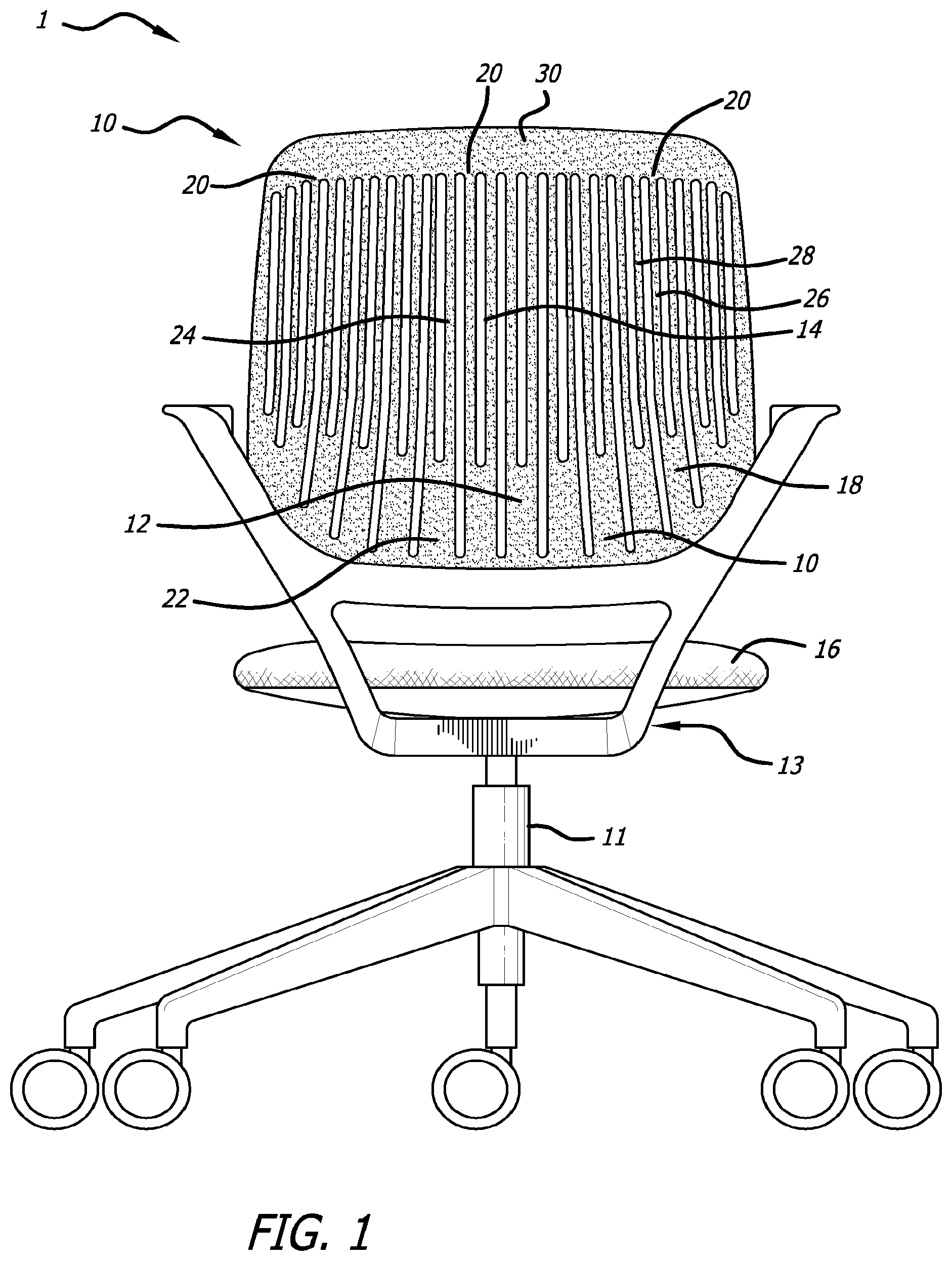
FIG. 1 is a back view of a back for a seating unit.
FIG. 1A is a back view of another embodiment of a back for a seating unit.
FIG. 1B is a cross-sectional view of the back of FIG. 1A taken along the line 1B-1B.
FIG. 2 is a perspective view of the back of FIG. 1.
FIG. 3 is a side view of the back of FIG. 1.
FIG. 3A is an enlarged view of the retainer of FIG. 3.
FIG. 3B is a top view of the chair back of FIG. 3.
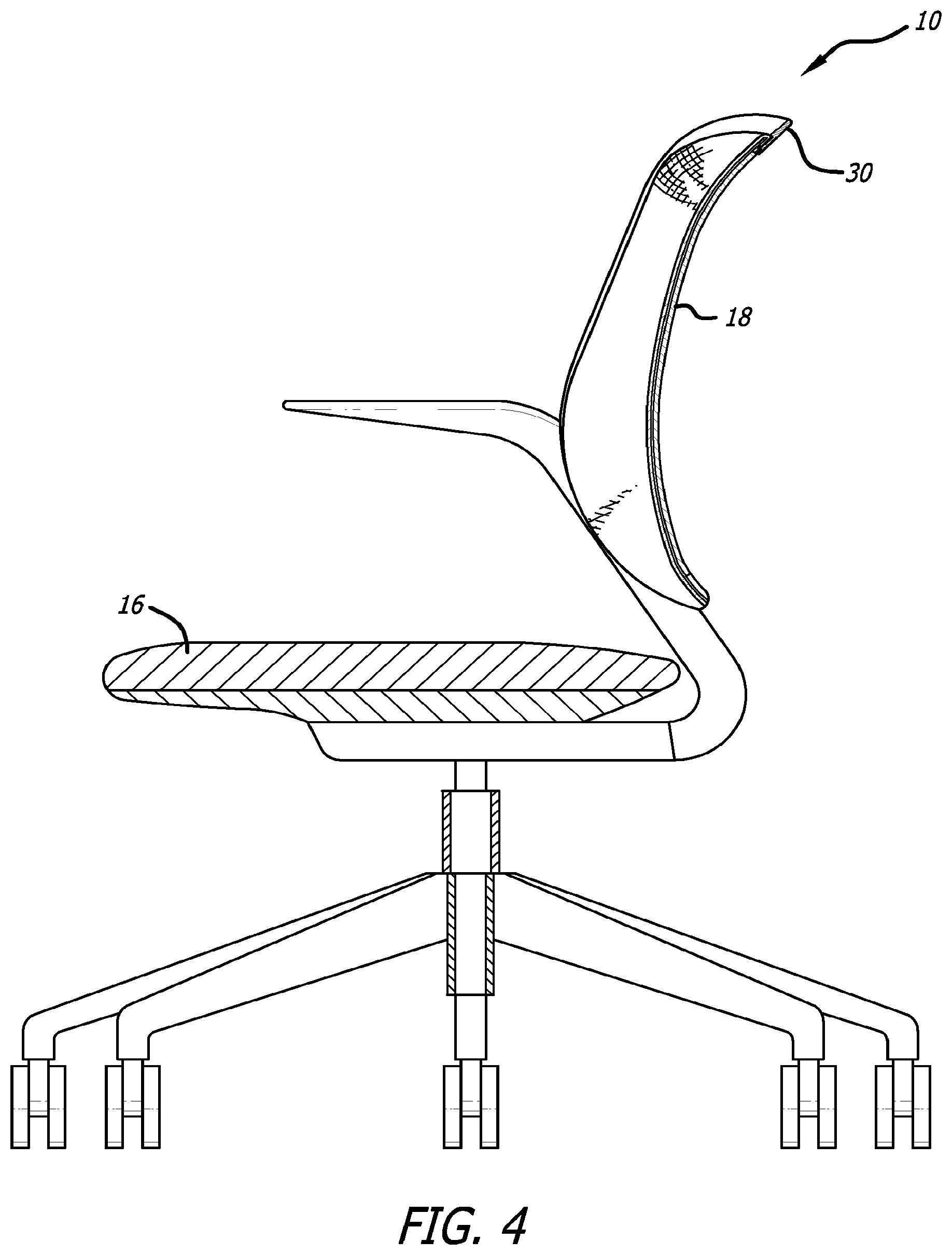
FIG. 4 shows the back of FIG. 3 when a load is applied.
FIG. 4A is a top view of the back of FIG. 4.
FIG. 5 is a back view of another back for a seating unit.
FIG. 6 is a perspective view of the back of FIG. 5.
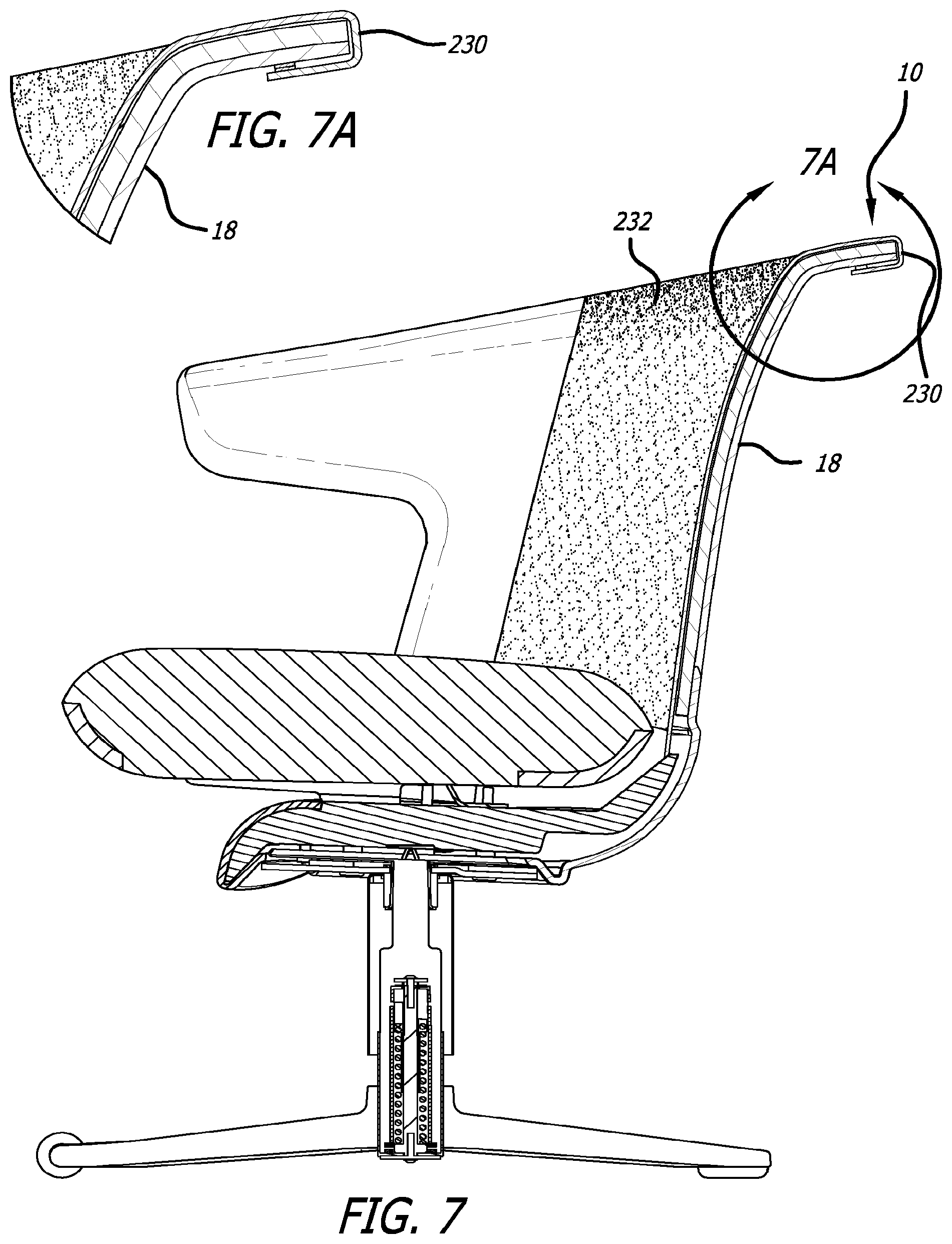
FIG. 7 is a side cross-sectional view of the back of FIG. 5.
FIG. 7A an enlarged view of the retainer of FIG. 7.
FIG. 8 shows the back of FIG. 7 when a load is applied.
FIG. 9 is a front perspective view of the back of FIG. 5 with fabric attached.
FIG. 10 shows the retainer being snapped onto the back of FIG. 5.
The components in the drawings are not necessarily to scale, emphasis instead being placed upon clearly illustrating the principles of the present invention.
DETAILED DESCRIPTION
While this invention is susceptible of embodiments in many different forms, there is shown in the drawings and will herein be described in detail preferred embodiments of the invention with the understanding that the present disclosure is to be considered as an exemplification of the principles of the invention and is not intended to limit the broad aspect of the invention to the embodiments illustrated.
As shown in FIGS. 1-10, a seating unit 1 incorporating a back 10 of the present invention typically includes a base 11, and a seat 16. The back 10 is typically coupled to the seat 16 or base such that the back 10 is disposed in a direction that is generally transverse to the generally horizontally disposed seat 16. The seat 16 and back 10 can be operably supported on a base 11 by an underseat control system 13. The seat and/or back may be supported on a frame or other structure. The back 10 may be connected to the seat 16, the base 11, the frame, other support structure or to another element.
The horizontally disposed seat 16 is merely meant to provide a relative position plane about which components of the seating unit 1 may be directionally arranged. And although it will be understood that the seat 16 is generally disposed horizontally, it will also be understood that the seat 16 may be disposed slightly off of the horizontal (e.g., an incline, etc.), and that the seat 16 may be contoured (e.g., concavely, including bolsters, etc.). Accordingly, it is also understood that because the back 10 is disposed in a direction that is generally transverse to the seat 16, the back 10 may be positioned at any angle that causes the back 10 to extend generally upward from the seat 16.
As shown in FIGS. 1-4, the back 10 generally includes a plurality of flexible finger elements 18, each having a distal end. In one embodiment of the invention, shown in FIGS. 1-2, the plurality of flexible finger elements 18 are disposed in a direction generally vertical relative to the seat 16. Each of the flexible finger elements 18 may flex a distance independent of the other flexible finger elements 18. It is preferable that there is some interdependency in the flexibility of some of the adjacent flexible finger elements 18 provided by a retainer 30 coupled to the flexible finger elements 18. Depending on the retainer 30, each of the flexible finger elements 18 may be capable of independently flexing a given distance as a result of an application of a force without necessitating that each of the other flexible finger elements 18 flex the same distance, or even at all.
The retainer 30 connects at least two of the flexible finger elements 18 proximate their distal ends. It is preferable that when a load is applied to at least one of the flexible finger elements 18, the load is transferred to at least one adjacent flexible finger element 18 via the retainer 30. When a load is applied to at least one of the flexible finger elements 18, the retainer 30 controls the distance the flexible finger element 18 flexes and how much each adjacent flexible finger element 18 flexes, as will be further described below. It is preferable that each of the flexible finger elements 18 are connected to at least one other flexible finger element 18 by the retainer 30. It is also preferable that flexible finger elements 18 connect to adjacent flexible finger elements 18 via the retainer 30. The flexible finger elements 18 and retainer 30 work as a unit to distribute an applied load.
In one embodiment of the invention, the retainer 30 defines at least part of an outer edge of the back 10 as shown by FIGS. 1-2. For example, the retainer 30 can define a portion of an upper edge of the back 10. The retainer 30 can also extend downward from the upper edge to define a portion or the entirety of the side edges of the back 10. The retainer 30 may be overmolded over the flexible finger elements 18, such as with a two-shot molding process. Alternatively, the retainer 30 may include a plurality of apertures or channels 21. The apertures 21 correspond to and retain the distal ends of the flexible finger elements 18. Alternatively, the flexible finger elements 18 may be mechanically attached to the retainer 30 such as with snaps, hooks, threaded through a ring, sewn, or otherwise attached. The retainer 30 could be a flexible strap such as an elastic strap or bungee coupled to the flexible finger elements 18. The retainer 30 forms an upper periphery of the back, it may extend above the distal ends of the flexible finger elements 18 and be adapted to bend at a position above the distal ends of the flexible finger elements 18 to form a ledge. This occurs when a user puts a load on the upper edge, such as by resting his or her arm over the upper edge.
As shown in FIGS. 1-4, the retainer 30 assists in distributing at least a portion of a load applied to the flexible finger elements 18. Accordingly, when a load is applied to the back 10, such as when the back of a seated user contacts the flexible finger elements 18, as a user moves against the back 10, the plurality of flexible finger elements 18 will articulate in a responsive serpentine-like movement to conform to the general form of the user, as well as to distribute the load among the flexible finger elements 18. When a user is seated in the seating unit 1 the flexible finger elements 18 conform to the user's body. As a seated user contacts the back 10, the force applied to each flexible finger element 18 the user contacts causes that flexible finger element 18 to flex. The flexible finger elements 18 cause the retainer 30 to move/flex adjacent flexible finger elements 18. The adjacent flexible finger elements 18 flex and move and the back 10 conforms to the user, wrapping around the user as each adjacent flexible finger element 18 moves to a lesser degree than the flexible finger elements 18 where force is directly applied by the user. The flexible finger elements 18 connected by the retainer 30 work in conjunction to conform to the contours of differing users. As a load is applied to at least one flexible finger element 18, it is transferred to adjacent flexible finger elements 18. The arrangement of the flexible finger elements 18 along the back 10 allows them to collectively provide support to a user. It also allows the back 10 to adjust and conform to a user's shifting positions.
According to the present invention, the retainer 30 has a third flexibility. The third flexibility may be greater than the flexibility provided by the flexible finger elements 18. The third flexibility primarily is attributable to the modulus of elasticity of the material used to form the retainer 30. According to one embodiment of the invention, the retainer 30 is made from thermoplastic olefin (TPO). However, it will be understood by those of skill in the art that the retainer 30 may be alternatively made from thermoplastic elastomers (TPE), rubber or any other material suitable for providing some flexibility in response to the application of a load. The material used for the retainer 30 may constrain and control the motion of the flexible finger elements 18 relative to adjacent flexible finger elements 18. Once it reaches the limit of elasticity, the retainer 30 may act as a limiter to constrain further flexing or movement of the flexible finger elements 18. Alternatively the orientation of the flex of the retainer 30 may be different than that of the flexible finger elements 18. That orientation can be adapted to control the movement of the flexible finger elements 18.
The retainer 30 could also be a relatively inflexible element which allows the flexible finger elements 18 to move independently, and act as a limiter to the flexing of the flexible finger elements 18 at a preselected distance. For example, the retainer 30 could be a cable or chain. As a load is applied to the flexible finger elements 18, slack in the retainer 30 would reduce until the retainer 30 is fully extended. The flexible finger elements 18 would thus be prevented from moving further and load would be distributed to adjacent flexible finger elements 18.
The back 10 may include a first flexible zone 22 of the back 10 and a second flexible zone 24 of the back 10. The first flexible zone 22 of the back 10 has a first flexibility, and the second flexible zone 24 of the back 10 has a second flexibility that is greater than the first flexibility. The first flexible zone 22 as shown in FIGS. 1-2 generally defines at least a portion of a lumbar region 12 of the back 10. The lumbar region 12 of the back 10 is the region near the bottom of the back 10. If a user were to be using the back 10, the lumbar region 12 would be proximate the user's lower spine. The second flexible 24 zone generally defines a portion of the back 10 extending from the lumbar region 12 through at least a portion of a thoracic region 14 of the back 10. The thoracic region 14 of the back 10 is the region disposed proximate to and above the lumbar region 12.
The degree of flexibility of the flexible finger elements 18, as well as the flexibility of the first and second flexible zones 22, 24, is dependent on many factors, including the configuration of the flexible finger elements 18, the modulus of elasticity of the material used to make the flexible finger elements 18, and the spacing between the flexible finger elements 18. According to one embodiment of the invention, the flexible finger elements 18 are made from polypropylene. However, it will be understood by those of skill in the art that the flexible finger elements 18 may be alternatively made from glass filled nylon, steel, fiberglass, or any other material suitable for providing some flexibility in response to the application of a load.
In one embodiment of the invention, each of the flexible finger elements 18 is spaced approximately 3/8 inch or less from one another. However, the scope of the present invention should not be limited by this exact spacing. One of skill in the art would understand that the spacing will be dictated by the material choice, length of the flexible finger elements 18, comfort, strength, manufacturing and other factors. Accordingly, the flexible finger elements 18 can be spaced at any distance suitable for providing some flexibility as a result of application of a load would.
The configuration of the flexible finger elements 18 may also cause a variation in the flexibility of the flexible finger elements 18 and between the first and second flexible zones 22, 24. As shown in FIGS. 1-2, the flexible finger elements 18 have greater width as they extend toward the lumbar region 12 from the thoracic region 14 of the back 10; the flexible finger elements 18 may be narrower in the thoracic region 14 as shown. The flexible finger elements 18 may taper toward their distal ends, or they may have a consistent profile. The difference in width of the flexible finger elements 18 can allow the second flexible zone 24 to be more flexible than the first flexible zone 22 even though the flexible finger elements 18 may be comprised of the same material.
According to one embodiment of the present invention, a distal end 20 of the flexible finger elements 18 is defined by a first flexible prong 26 and a second flexible prong 28. In this embodiment, the distal ends of the prongs 26, 28 are connected to the retainer 30. Thus, the first and second flexible prongs 26, 28 define the second zone of flexibility 24. This configuration can provide even greater variation in flexibility between flexible finger elements 18 and flexible zones 22, 24. The prongs 26, 28 allow for differing back contours, as the seated user moves or changes postures in the chair, which result from the differing back flex. Accordingly, in this configuration, the first flexible prong 26 can also be flexible independent of the second flexible prong 28. In the embodiment shown, the flexible prongs 26, 28 are integrally formed with the flexible finger elements 18. However, it is contemplated that the flexible prongs 26, 28 may also be separate components that are attachably coupled to the distal ends of the flexible finger elements 18 by known connectors. It is also contemplated by the present invention that some of the plurality of flexible finger elements 18 include flexible prongs 26, 28, while other of the flexible finger elements 18 do not include flexible prongs 26, 28.
The degree of flexibility of each of the flexible prongs 26, 28 is dependent on many factors, including the configuration of the flexible prongs 26, 28, the modulus of elasticity of the material used to make the flexible prongs 26, 28, and the spacing between the flexible prongs 26, 28. According to one embodiment of the invention, the flexible prongs 26, 28 are made from polypropylene. However, it will be understood by those of skill in the art that the flexible prongs 26, 28 may be alternatively made from glass filled nylon, steel or any other material suitable for providing some flexibility in response to the application of a load.
In one embodiment, shown in FIGS. 5-6, the retainer 230 may be a stretchable fabric bungee, elastomeric material or other semi-stretchable material coupled to the distal ends of the flexible finger elements 18. The retainer 230 is mechanically connected to the flexible finger elements 18, such as with snaps 240 as shown in FIG. 10. Other known attachment techniques could also be used. Alternatively, the retainer 230 could have pockets adapted to receive the ends of the flexible finger elements 18. The ends of the retainer 30 are secured to a structural frame of the seating unit 1.
In this embodiment, the retainer 230 has inherent characteristics such that the retainer 230 absorbs some of the load that may be applied to the flexible finger elements 18. As a load is applied to the flexible finger elements 18, they tend to spread apart. The retainer 230 limits the collective spreading of the flexible finger elements 18. According to this embodiment, the retainer 230 is preferably made from an elastic strap. However, it will be understood by those of skill in the art that the retainer 230 of this embodiment may be alternatively made from elastomeric material, bungee material, rubber, springs or any other suitable material. The elastic material of the retainer 230 preferably has two rates of flex recovery. The first limits the spread of the flexible finger elements 18. The second limits ultimate travel of the flexible finger elements 18 and ensures stability of the flexible finger elements 18 under heavy loads. Alternatively, two materials could be used cooperatively to form a retainer 230 with the desired flex characteristics. For example, two retainers 230 may be used, wherein one is flexible and one is inflexible. The first flexible retainer transfers load to adjacent flexible finger elements 18, and the second inflexible retainer limits ultimate travel of the flexible finger elements 18 when the slack is taken up. As a user sits in the chair and applies a load to the flexible finger elements 18, the elasticity of the fingers permits the fingers to spread allowing the back to conform to the user in the area proximate where the user is contacting the back 10. The barrel shape of the back 10 allows the user to sit in a variety of alternative postures. Further both the back 10 and the seat 16 can rotate. A user may wish to sit with his back toward one or the other of the armrests rather than the center of the back. The back 10 could be rotated so that the armrest is in front of the user with the side of the user contacting the back 10. The side of a user has a different contour and different comfort needs than a user's back.
In another embodiment, the retainer 230 may be constructed of a relatively inflexible material such as cable or chain. The flexible finger elements 18 would still be able to flex a certain distance; however, when the flexible finger elements 18 flexed a distance such that slack in the cable or chain is taken up, further flex of the flexible finger elements 18 would be constrained by the retainer 230.
While the retainers 30, 230 shown in FIGS. 1-2 and 5-6 are single continuous retainers, it is also contemplated that the retainer may be segmented such that several retainers are employed. If separate retainers are used, they may have varying rates of elastic return to proscribe motion differently in different areas of the back 10.
As shown in FIG. 9, the seating unit may be upholstered. The flexible finger elements 18 could be exposed and visible as in FIGS. 5-6, or the fingers could be hidden by a fabric 232 and have the visual of a fully upholstered seating unit. The fabric 232 may cover at least a portion of the plurality of flexible finger elements 18. According to the present invention, the fabric 232 is sufficiently flexible such that it does not significantly hinder the flexibility of the flexible finger elements 18. Further, the fabric 232 will work in conjunction with the retainer 230 to both distribute the load applied between the flexible finger elements 18 and limit the collective spreading of the flexible finger elements 18. The flexible finger elements 18, retainer 230 and fabric 232 work as a unit to distribute loads.
The fabric 232 may be attached to a ring or spline element which is secured in a channel in the back 10. When a load is applied to the back 10, a portion of the load is transferred to fabric 232 which goes into tension limiting the distance the flexible finger elements 18 may travel.
The fabric 232 may also be attached to the retainer 230 as show in FIG. 6. The fabric 232 is also upholstered to the frame and is attached under the seat 16 with a flexible webbing. When a load is applied to the flexible finger elements 18, the fabric 232 may be pulled vertically and/or horizontally. The limit of flexibility of the fabric 232 limits and controls the movement of the flexible finger elements 18. Thus, the flexible finger elements 18, the retainer 230 and the fabric 232 work as a unit to absorb load. When the fabric 232 stretches in the horizontal direction, the fabric 232 is "shortened" in the vertical direction. Including a flexible webbing or skirt at the bottom of the back 10, prevents the fabric 232 from puddling or from stretching and holding an undesired set.
The present invention has been described above with reference to exemplary embodiments. However, those skilled in the art having read this disclosure will recognize that changes and modifications may be made to the exemplary embodiments without departing from the scope of the present invention.
* * * * *
D00000
D00001
D00002
D00003
D00004
D00005
D00006
D00007
D00008
D00009
D00010
D00011
D00012

XML
uspto.report is an independent third-party trademark research tool that is not affiliated, endorsed, or sponsored by the United States Patent and Trademark Office (USPTO) or any other governmental organization. The information provided by uspto.report is based on publicly available data at the time of writing and is intended for informational purposes only.
While we strive to provide accurate and up-to-date information, we do not guarantee the accuracy, completeness, reliability, or suitability of the information displayed on this site. The use of this site is at your own risk. Any reliance you place on such information is therefore strictly at your own risk.
All official trademark data, including owner information, should be verified by visiting the official USPTO website at www.uspto.gov. This site is not intended to replace professional legal advice and should not be used as a substitute for consulting with a legal professional who is knowledgeable about trademark law.