Compression sleeve with improved position retention
Avitable , et al. A
U.S. patent number 10,751,221 [Application Number 12/881,245] was granted by the patent office on 2020-08-25 for compression sleeve with improved position retention. This patent grant is currently assigned to KPR U.S., LLC. The grantee listed for this patent is Raymond C. Avitable, Del Brooks, Ross Kanter. Invention is credited to Raymond C. Avitable, Del Brooks, Ross Kanter.


View All Diagrams
| United States Patent | 10,751,221 |
| Avitable , et al. | August 25, 2020 |
Compression sleeve with improved position retention
Abstract
A compression garment having first and second sections includes a stay up device for supporting the compression garment in position on the body. The stay up device is constructed to operatively engage a portion of the body to positively locate the stay up device, and thereby the garment relative to the body.
| Inventors: | Avitable; Raymond C. (Framingham, MA), Kanter; Ross (Wrentham, MA), Brooks; Del (Seneca, SC) | ||||||||||
|---|---|---|---|---|---|---|---|---|---|---|---|
| Applicant: |
|
||||||||||
| Assignee: | KPR U.S., LLC (Mansfield,
MA) |
||||||||||
| Family ID: | 44645569 | ||||||||||
| Appl. No.: | 12/881,245 | ||||||||||
| Filed: | September 14, 2010 |
Prior Publication Data
| Document Identifier | Publication Date | |
|---|---|---|
| US 20120065664 A1 | Mar 15, 2012 | |
| Current U.S. Class: | 1/1 |
| Current CPC Class: | A61F 13/06 (20130101); A61B 17/00 (20130101); A61H 9/0092 (20130101); A61H 9/0078 (20130101); A61F 13/00995 (20130101); A61B 17/12 (20130101); A61F 13/085 (20130101); A61F 2013/00174 (20130101); A61H 2201/1697 (20130101) |
| Current International Class: | A61B 17/00 (20060101); A61F 13/00 (20060101); A61F 13/06 (20060101); A61F 13/08 (20060101); A61H 9/00 (20060101); A61B 17/12 (20060101) |
References Cited [Referenced By]
U.S. Patent Documents
| 908959 | January 1909 | Cooke |
| 910689 | January 1909 | Kelly et al. |
| 1510482 | October 1924 | Kramer |
| 1608239 | November 1926 | Rosett |
| 2199408 | May 1940 | La Liberte |
| 2250617 | July 1941 | Argentin |
| 2489388 | November 1949 | Rubin |
| 2533504 | December 1950 | Poor |
| 2638915 | May 1953 | Mitchell |
| 2676587 | April 1954 | Corcoran |
| 2694395 | November 1954 | Brown |
| 2853998 | September 1958 | Emerson |
| 2880721 | April 1959 | Corcoran |
| 2896612 | July 1959 | Bates et al. |
| 2998817 | September 1961 | Armstrong |
| 3164152 | January 1965 | Vere Nicoll |
| 3245405 | April 1966 | Gardner |
| 3288132 | November 1966 | Meredith |
| 3351055 | November 1967 | Gottfried |
| 3454010 | July 1969 | Lilligren et al. |
| 3469769 | September 1969 | Guenther |
| 3473527 | October 1969 | Spiro |
| 3504675 | April 1970 | Bishop, Jr. |
| 3561435 | February 1971 | Nicholson |
| 3568227 | March 1971 | Dunham |
| 3606880 | September 1971 | Ogle, Jr. |
| 3638334 | February 1972 | Malikowski |
| 3701173 | October 1972 | Whitney |
| 3728875 | April 1973 | Hartigan et al. |
| 3760795 | September 1973 | Adelhed |
| 3770040 | November 1973 | De Cicco |
| 3771519 | November 1973 | Haake |
| 3786805 | January 1974 | Tourin |
| 3824992 | July 1974 | Nicholson et al. |
| 3826249 | July 1974 | Lee et al. |
| 3862629 | January 1975 | Rotta |
| 3868952 | March 1975 | Hatton |
| 3877426 | April 1975 | Nirschl |
| 3878839 | April 1975 | Norton et al. |
| 3899210 | August 1975 | Samhammer et al. |
| 3901221 | August 1975 | Nicholson et al. |
| 3906937 | September 1975 | Aronson |
| 3920006 | November 1975 | Lapidus |
| D239981 | May 1976 | Arbuck et al. |
| 3955565 | May 1976 | Johnson, Jr. |
| 4013069 | March 1977 | Hasty |
| 4029087 | June 1977 | Dye et al. |
| 4030488 | June 1977 | Hasty |
| 4054129 | October 1977 | Byars et al. |
| 4066084 | January 1978 | Tillander |
| 4076022 | February 1978 | Walker |
| 4091804 | May 1978 | Hasty |
| 4116236 | September 1978 | Albert |
| 4146021 | March 1979 | Brosseau et al. |
| 4149529 | April 1979 | Copeland et al. |
| 4149541 | April 1979 | Gammons et al. |
| 4153050 | May 1979 | Bishop et al. |
| 4156425 | May 1979 | Arkans |
| 4197837 | April 1980 | Tringali et al. |
| 4198961 | April 1980 | Arkans |
| 4201203 | May 1980 | Applegate |
| 4202312 | May 1980 | Mori et al. |
| 4202325 | May 1980 | Villari et al. |
| 4206751 | June 1980 | Schneider |
| 4207875 | June 1980 | Arkans |
| 4207876 | June 1980 | Annis |
| 4219892 | September 1980 | Rigdon |
| 4253449 | March 1981 | Arkans et al. |
| D259058 | April 1981 | Marshall |
| 4267611 | May 1981 | Agulnick |
| 4270527 | June 1981 | Peters et al. |
| 4280485 | July 1981 | Arkans |
| 4294238 | October 1981 | Woodford |
| 4294240 | October 1981 | Thill |
| 4300245 | November 1981 | Saunders |
| 4308862 | January 1982 | Kalmar |
| 4311135 | January 1982 | Brueckner et al. |
| 4320746 | March 1982 | Arkans et al. |
| 4343302 | August 1982 | Dillon |
| 4352253 | October 1982 | Oswalt |
| 4355632 | October 1982 | Sandman |
| 4363125 | December 1982 | Brewer et al. |
| 4372297 | February 1983 | Perlin |
| 4375217 | March 1983 | Arkans |
| 4379217 | April 1983 | Youmans |
| 4402312 | September 1983 | Villari |
| 4408599 | October 1983 | Mummert |
| 4417587 | November 1983 | Ichinomiya et al. |
| 4425912 | January 1984 | Harper |
| 4437269 | March 1984 | Shaw |
| 4442834 | April 1984 | Tucker et al. |
| 4445505 | May 1984 | Labour et al. |
| 4453538 | June 1984 | Whitney |
| 4522197 | June 1985 | Hasegawa |
| 4531516 | July 1985 | Poole et al. |
| 4547906 | October 1985 | Nishida et al. |
| 4547919 | October 1985 | Wang |
| 4552821 | November 1985 | Gibbard et al. |
| 4580816 | April 1986 | Campbell et al. |
| 4583255 | April 1986 | Mogaki et al. |
| 4593692 | June 1986 | Flowers |
| 4597384 | July 1986 | Whitney |
| 4614180 | September 1986 | Gardner et al. |
| 4624244 | November 1986 | Taheri |
| 4650452 | March 1987 | Jensen |
| 4657003 | April 1987 | Wirtz |
| 4682588 | July 1987 | Curlee |
| 4696289 | September 1987 | Gardner et al. |
| 4699424 | October 1987 | Andres et al. |
| 4702232 | October 1987 | Gardner et al. |
| 4703750 | November 1987 | Sebastian et al. |
| 4706658 | November 1987 | Cronin |
| 4722332 | February 1988 | Saggers |
| 4730606 | March 1988 | Leininger |
| 4753649 | June 1988 | Pazdernik |
| 4762121 | August 1988 | Shienfeld |
| 4773397 | September 1988 | Wright et al. |
| 4805620 | February 1989 | Meistrell |
| 4809684 | March 1989 | Gardner et al. |
| 4827912 | May 1989 | Carrington et al. |
| 4832010 | May 1989 | Lerman |
| RE32939 | June 1989 | Gardner et al. |
| RE32940 | June 1989 | Gardner et al. |
| 4836194 | June 1989 | Sebastian et al. |
| 4836691 | June 1989 | Suzuki et al. |
| D302301 | July 1989 | Robinette-Lehman |
| 4846189 | July 1989 | Sun |
| 4869265 | September 1989 | McEwen |
| 4872448 | October 1989 | Johnson, Jr. |
| 4876788 | October 1989 | Steer et al. |
| 4883073 | November 1989 | Aziz |
| 4886053 | December 1989 | Neal |
| 4898160 | February 1990 | Brownlee |
| 4913136 | April 1990 | Chong et al. |
| 4938207 | July 1990 | Vargo |
| 4938208 | July 1990 | Dye |
| 4938226 | July 1990 | Danielsson et al. |
| 4945571 | August 1990 | Calvert |
| 4947834 | August 1990 | Kartheus et al. |
| 4957105 | September 1990 | Kurth |
| 4960115 | October 1990 | Ranciato |
| 4964402 | October 1990 | Grim et al. |
| 4977891 | December 1990 | Grim |
| 4979953 | December 1990 | Spence |
| 4986263 | January 1991 | Dickerson |
| 4989273 | February 1991 | Cromartie |
| 4997452 | March 1991 | Kovach et al. |
| 5007411 | April 1991 | Dye |
| 5014681 | May 1991 | Neeman et al. |
| 5022387 | June 1991 | Hasty |
| 5031604 | July 1991 | Dye |
| 5048536 | September 1991 | McEwen |
| 5052377 | October 1991 | Frajdenrajch |
| 5062414 | November 1991 | Grim |
| 5069219 | December 1991 | Knoblich |
| 5071415 | December 1991 | Takemoto |
| 5080951 | January 1992 | Guthrie |
| 5082284 | January 1992 | Reed |
| 5109832 | May 1992 | Proctor et al. |
| 5117812 | June 1992 | McWhorter |
| 5120300 | June 1992 | Shaw |
| 5135473 | August 1992 | Epler et al. |
| 5139475 | August 1992 | Peters |
| 5139476 | August 1992 | Peters |
| 5139479 | August 1992 | Peters |
| 5146932 | September 1992 | McCabe |
| 5156629 | October 1992 | Shane et al. |
| 5158541 | October 1992 | McCurley |
| 5168576 | December 1992 | Krent et al. |
| 5172689 | December 1992 | Wright |
| D332495 | January 1993 | Lake |
| 5179941 | January 1993 | Siemssen et al. |
| 5181522 | January 1993 | McEwen |
| 5186163 | February 1993 | Dye |
| 5193549 | March 1993 | Bellin et al. |
| 5211162 | May 1993 | Gillen, Jr. et al. |
| 5226245 | July 1993 | Lamont |
| 5228478 | July 1993 | Kleisle |
| 5230335 | July 1993 | Johnson, Jr. et al. |
| 5245990 | September 1993 | Bertinin |
| 5259397 | November 1993 | McCabe |
| 5261871 | November 1993 | Greenfield |
| 5263473 | November 1993 | McWhorter |
| 5275588 | January 1994 | Matsumoto et al. |
| 5277695 | January 1994 | Johnson, Jr. et al. |
| 5277697 | January 1994 | France et al. |
| 5288286 | February 1994 | Davis et al. |
| 5312431 | May 1994 | McEwen |
| 5314455 | May 1994 | Johnson, Jr. et al. |
| 5334135 | August 1994 | Grim et al. |
| 5342285 | August 1994 | Dye |
| 5354260 | October 1994 | Cook |
| 5378224 | January 1995 | Billotti |
| 5383894 | January 1995 | Dye |
| 5383919 | January 1995 | Kelly et al. |
| 5385538 | January 1995 | Mann |
| 5389065 | February 1995 | Johnson, Jr. |
| 5391141 | February 1995 | Hamilton |
| 5399153 | March 1995 | Caprio, Jr. et al. |
| 5403265 | April 1995 | Berguer et al. |
| 5406661 | April 1995 | Pekar |
| 5407421 | April 1995 | Goldsmith |
| D358216 | May 1995 | Dye |
| 5411037 | May 1995 | Hess |
| 5413582 | May 1995 | Eaton |
| 5419757 | May 1995 | Daneshvar |
| 5425701 | June 1995 | Oster et al. |
| 5435009 | July 1995 | Schild et al. |
| 5437595 | August 1995 | Smith |
| 5437610 | August 1995 | Cariapa et al. |
| 5441533 | August 1995 | Johnson et al. |
| 5443440 | August 1995 | Tumey et al. |
| 5449341 | September 1995 | Harris |
| 5449379 | September 1995 | Hadtke |
| 5450858 | September 1995 | Zablotsky et al. |
| 5451201 | September 1995 | Prengler |
| 5453081 | September 1995 | Hansen |
| 5455969 | October 1995 | Pratson et al. |
| 5458265 | October 1995 | Hester et al. |
| 5462517 | October 1995 | Mann |
| 5466250 | November 1995 | Johnson, Jr. et al. |
| 5470156 | November 1995 | May |
| 5478119 | December 1995 | Dye |
| 5489259 | February 1996 | Jacobs et al. |
| 5496262 | March 1996 | Johnson, Jr. et al. |
| 5503620 | April 1996 | Danzger |
| 5511552 | April 1996 | Johnson |
| 5513658 | May 1996 | Goseki |
| 5514081 | May 1996 | Mann |
| 5514155 | May 1996 | Daneshvar |
| 5527267 | June 1996 | Billotti |
| 5554105 | September 1996 | Taylor |
| D376013 | November 1996 | Sandman et al. |
| 5575762 | November 1996 | Peeler et al. |
| 5578055 | November 1996 | McEwen |
| 5584798 | December 1996 | Fox |
| 5588954 | December 1996 | Ribando et al. |
| 5588955 | December 1996 | Johnson, Jr. et al. |
| 5588956 | December 1996 | Billotti |
| 5591200 | January 1997 | Cone et al. |
| 5591337 | January 1997 | Lynn et al. |
| 5603690 | February 1997 | Barry |
| 5609570 | March 1997 | Lamont |
| 5620411 | April 1997 | Schumann et al. |
| 5622113 | April 1997 | Hansen |
| 5626556 | May 1997 | Tobler et al. |
| 5626557 | May 1997 | Mann |
| 5634889 | June 1997 | Gardner et al. |
| 5637106 | June 1997 | Mitchell et al. |
| 5640714 | June 1997 | Tanaka |
| 5649954 | July 1997 | McEwen |
| 5653244 | August 1997 | Shaw |
| D383547 | September 1997 | Mason et al. |
| 5664270 | September 1997 | Bell et al. |
| 5669872 | September 1997 | Fox |
| 5673028 | September 1997 | Levy |
| 5674262 | October 1997 | Tumey |
| 5695453 | December 1997 | Neal |
| 5704999 | January 1998 | Lukich et al. |
| 5711757 | January 1998 | Bryant |
| 5711760 | January 1998 | Ibrahim |
| 5717996 | February 1998 | Feldmann |
| 5728055 | March 1998 | Sebastian |
| 5728057 | March 1998 | Ouellette et al. |
| 5730710 | March 1998 | Eichhorn et al. |
| 5733304 | March 1998 | Spence |
| 5741295 | April 1998 | McEwen |
| 5746213 | May 1998 | Marks |
| 5759167 | June 1998 | Shields et al. |
| 5765298 | June 1998 | Potter et al. |
| 5769800 | June 1998 | Gelfand et al. |
| 5769801 | June 1998 | Tumey et al. |
| 5790998 | August 1998 | Crescimbeni |
| 5795312 | August 1998 | Dye |
| 5797851 | August 1998 | Byrd |
| 5823981 | October 1998 | Grim |
| 5833639 | November 1998 | Nunes et al. |
| 5840049 | November 1998 | Tumey et al. |
| 5843007 | December 1998 | McEwen et al. |
| D403775 | January 1999 | Davis et al. |
| D405884 | February 1999 | Roper |
| 5876359 | March 1999 | Bock et al. |
| 5891065 | April 1999 | Cariapa et al. |
| 5894682 | April 1999 | Broz |
| D411301 | June 1999 | Hampson et al. |
| 5916183 | June 1999 | Reid |
| 5925010 | July 1999 | Caprio, Jr. |
| 5926850 | July 1999 | Han |
| 5938628 | August 1999 | Oguri et al. |
| 5951502 | September 1999 | Peeler et al. |
| 5957872 | September 1999 | Flick |
| 5966763 | October 1999 | Thomas et al. |
| 5968072 | October 1999 | Hite et al. |
| 5970519 | October 1999 | Weber |
| 5976099 | November 1999 | Kellogg |
| 5976300 | November 1999 | Buchanan et al. |
| 5988704 | November 1999 | Ryhman |
| 5989204 | November 1999 | Lina |
| 5991654 | November 1999 | Tumey et al. |
| 5997495 | December 1999 | Cook et al. |
| 5997981 | December 1999 | McCormack et al. |
| 6001119 | December 1999 | Hampson et al. |
| 6007559 | December 1999 | Arkans |
| 6010471 | January 2000 | Ben-Noon |
| 6021780 | February 2000 | Darby |
| 6036718 | March 2000 | Ledford et al. |
| 6048326 | April 2000 | Davis et al. |
| 6051016 | April 2000 | Mesaros et al. |
| 6056713 | May 2000 | Hayashi |
| 6062244 | May 2000 | Arkans |
| 6066217 | May 2000 | Dibble et al. |
| 6076193 | June 2000 | Hood |
| 6080120 | June 2000 | Sandman et al. |
| D428153 | July 2000 | Davis |
| 6110135 | August 2000 | Madow et al. |
| 6120469 | September 2000 | Bruder |
| 6126683 | October 2000 | Momtaheni |
| 6129688 | October 2000 | Arkans |
| 6129695 | October 2000 | Peters et al. |
| 6134720 | October 2000 | Foreman |
| 6135116 | October 2000 | Vogel et al. |
| 6145143 | November 2000 | Hicks et al. |
| 6149600 | November 2000 | Poorman-Ketchum |
| 6149616 | November 2000 | Szlema et al. |
| 6152495 | November 2000 | Hoffmann et al. |
| 6152893 | November 2000 | Pigg et al. |
| 6168539 | January 2001 | Maina |
| 6171271 | January 2001 | Hornberg |
| 6179796 | January 2001 | Waldridge |
| 6197045 | March 2001 | Carson |
| 6203510 | March 2001 | Takeuchi |
| 6231532 | March 2001 | Watson et al. |
| 6209159 | April 2001 | Murphy |
| 6212719 | April 2001 | Thomas et al. |
| 6231507 | May 2001 | Zikorus et al. |
| 6245023 | June 2001 | Clemmons |
| 6254554 | July 2001 | Turtzo |
| 6257626 | July 2001 | Campau |
| 6257627 | July 2001 | Fujiwara et al. |
| 6260201 | July 2001 | Rankin |
| 6290662 | September 2001 | Morris et al. |
| 6290664 | September 2001 | Nauert |
| 6315745 | November 2001 | Kloecker |
| 6319215 | November 2001 | Manor et al. |
| 6322530 | November 2001 | Johnson, Jr. et al. |
| 6336935 | January 2002 | Davis et al. |
| 6338723 | January 2002 | Carpenter et al. |
| 6349506 | February 2002 | Pace et al. |
| 6358219 | March 2002 | Arkans |
| 6368357 | April 2002 | Schon et al. |
| 6375633 | April 2002 | Endress et al. |
| 6385778 | May 2002 | Johnson |
| 6385864 | May 2002 | Sell, Jr. et al. |
| 6387065 | May 2002 | Tumey |
| 6402879 | June 2002 | Tawney et al. |
| 6409691 | June 2002 | Dakin et al. |
| 6423053 | July 2002 | Lee |
| 6436064 | August 2002 | Kloecker |
| 6440093 | August 2002 | McEwen et al. |
| 6447460 | September 2002 | Zheng et al. |
| 6463934 | October 2002 | Johnson, Jr. et al. |
| 6468237 | October 2002 | Lina |
| 6478757 | November 2002 | Barak |
| 6478761 | November 2002 | Bracamonte-Sommer |
| 6488643 | December 2002 | Tumey et al. |
| 6494852 | December 2002 | Barak et al. |
| 6508205 | January 2003 | Zink |
| 6520926 | February 2003 | Hall |
| 6526597 | March 2003 | Shepard |
| 6527727 | March 2003 | Itonaga et al. |
| 6537298 | March 2003 | Dedo |
| 6540707 | April 2003 | Stark et al. |
| 6544202 | April 2003 | McEwen et al. |
| 6549748 | April 2003 | Miura |
| 6551280 | April 2003 | Knighton et al. |
| 6554785 | April 2003 | Sroufe et al. |
| 6557704 | May 2003 | Randolph |
| 6558338 | May 2003 | Wasserman |
| 6562060 | May 2003 | Momtaheni |
| 6589267 | July 2003 | Hui |
| 6589534 | July 2003 | Shaul et al. |
| 6592534 | July 2003 | Rutt et al. |
| 6593508 | July 2003 | Harder |
| 6598249 | July 2003 | Pajanacci et al. |
| D478995 | August 2003 | Cipra et al. |
| 6616622 | September 2003 | Barberio |
| 6618859 | September 2003 | Kadymir et al. |
| 6629941 | October 2003 | Ishibashi et al. |
| 6645165 | November 2003 | Waldridge et al. |
| D484986 | January 2004 | Cipra et al. |
| 6676614 | January 2004 | Hansen et al. |
| 6682547 | January 2004 | McEwen et al. |
| 6685661 | February 2004 | Peled |
| 6719711 | April 2004 | Islava |
| 6726641 | April 2004 | Chiang et al. |
| 6746470 | June 2004 | McEwen et al. |
| 6762337 | July 2004 | Boukanov et al. |
| 6762338 | July 2004 | Harder |
| 6842915 | January 2005 | Turner et al. |
| 6846294 | January 2005 | Rastegar et al. |
| 6846295 | January 2005 | Ben-Nun |
| 6849057 | February 2005 | Satou et al. |
| 6852089 | February 2005 | Kloecker et al. |
| 6860862 | March 2005 | Waldridge et al. |
| 6862989 | March 2005 | Belanger et al. |
| 6866636 | March 2005 | Inoue et al. |
| 6869409 | March 2005 | Rothman et al. |
| D506553 | June 2005 | Tesluk |
| 6945944 | September 2005 | Kuiper et al. |
| D510626 | October 2005 | Krahner et al. |
| 6973690 | December 2005 | Muci et al. |
| 6984215 | January 2006 | Shah et al. |
| 6991613 | January 2006 | Sensabaugh |
| 7011640 | March 2006 | Patterson et al. |
| 7022096 | April 2006 | Alfieri |
| 7041074 | May 2006 | Averianov et al. |
| 7044924 | May 2006 | Roth et al. |
| 7048703 | May 2006 | Riach |
| 7083586 | August 2006 | Simmons |
| 7090500 | August 2006 | Guttman |
| D533668 | December 2006 | Brown |
| 7166077 | January 2007 | Millay et al. |
| 7217249 | May 2007 | Scott |
| D545972 | July 2007 | Wierenga et al. |
| 7237272 | July 2007 | Botcher |
| 7238080 | July 2007 | Gimble |
| 7258676 | August 2007 | Calderon et al. |
| D550367 | September 2007 | Nash |
| 7276037 | October 2007 | Ravikumar |
| 7276039 | October 2007 | Garelick et al. |
| 7278980 | October 2007 | Garelick et al. |
| 7282038 | October 2007 | Gillis et al. |
| 7285103 | October 2007 | Nathanson |
| 7288076 | October 2007 | Grim et al. |
| 7297128 | November 2007 | Binder et al. |
| 7300410 | November 2007 | Weber |
| 7303539 | December 2007 | Binder et al. |
| 7306568 | December 2007 | Diana |
| 7310847 | December 2007 | Bolkan et al. |
| 7318812 | January 2008 | Taylor et al. |
| D562461 | February 2008 | Nash |
| D562462 | February 2008 | Muir et al. |
| 7326227 | February 2008 | Dedo et al. |
| 7329232 | February 2008 | Lipshaw et al. |
| 7351217 | April 2008 | Scherpenborg |
| 7353770 | April 2008 | Sanguinetti |
| 7354410 | April 2008 | Perry et al. |
| 7354411 | April 2008 | Perry et al. |
| 7374550 | May 2008 | Hansen et al. |
| D577124 | September 2008 | Freeland et al. |
| 7424936 | September 2008 | McClellan |
| 7442175 | October 2008 | Meyer |
| 7465283 | December 2008 | Grim et al. |
| 7468048 | December 2008 | Meehan |
| 7473816 | January 2009 | Hall |
| D594561 | June 2009 | Freeland et al. |
| 7543399 | June 2009 | Kilgore et al. |
| 7559908 | July 2009 | Ravikumar |
| 7578799 | August 2009 | Thorsteinsson et al. |
| 7591796 | September 2009 | Barak et al. |
| 7591797 | September 2009 | Hakonson et al. |
| 7597675 | October 2009 | Ingimundarson et al. |
| 7615027 | November 2009 | Nordt, III et al. |
| 7618389 | November 2009 | Nordt, III et al. |
| 7625348 | December 2009 | Young et al. |
| 7637879 | December 2009 | Barak et al. |
| D608006 | January 2010 | Avitable et al. |
| 7654117 | February 2010 | Barnett |
| 7748090 | July 2010 | Seth et al. |
| 7766890 | August 2010 | Ito et al. |
| 7780698 | August 2010 | McEwen et al. |
| 7803358 | September 2010 | Gordan et al. |
| 7827624 | November 2010 | Cole |
| 8177734 | May 2012 | Vess |
| 8419666 | April 2013 | Liu et al. |
| 8506508 | August 2013 | Avitable |
| 2001/0018564 | August 2001 | Manor et al. |
| 2002/0068886 | June 2002 | Lin |
| 2002/0069731 | June 2002 | Soucy |
| 2002/0115949 | August 2002 | Kuslich et al. |
| 2002/0121235 | September 2002 | Carpenter et al. |
| 2003/0018313 | January 2003 | Tanzer et al. |
| 2003/0065357 | April 2003 | Dedo et al. |
| 2003/0083605 | May 2003 | Edmund |
| 2003/0130644 | July 2003 | Baker |
| 2003/0191420 | October 2003 | Kuiper et al. |
| 2003/0199922 | October 2003 | Buckman |
| 2004/0010212 | January 2004 | Kuiper et al. |
| 2004/0039317 | February 2004 | Souney et al. |
| 2004/0039413 | February 2004 | Akerfeldt et al. |
| 2004/0054306 | March 2004 | Roth et al. |
| 2004/0068290 | April 2004 | Bates et al. |
| 2004/0097860 | May 2004 | Tauber |
| 2004/0158283 | August 2004 | Shook et al. |
| 2004/0158285 | August 2004 | Pillai |
| 2004/0176715 | September 2004 | Nelson |
| 2004/0181156 | September 2004 | Kingsford et al. |
| 2004/0181254 | September 2004 | Choi et al. |
| 2004/0199090 | October 2004 | Sanders et al. |
| 2004/0210167 | October 2004 | Webster |
| 2004/0236258 | November 2004 | Burns et al. |
| 2005/0070828 | March 2005 | Hampson et al. |
| 2005/0154336 | July 2005 | Kloecker et al. |
| 2005/0165340 | July 2005 | Dunn |
| 2005/0187503 | August 2005 | Tordella et al. |
| 2005/0209545 | September 2005 | Farrow et al. |
| 2005/0242315 | November 2005 | Lund |
| 2006/0010574 | January 2006 | Linnane et al. |
| 2006/0020236 | January 2006 | Ben-Nun |
| 2006/0026736 | February 2006 | Nordt et al. |
| 2006/0089617 | April 2006 | Bunnelle |
| 2006/0102423 | May 2006 | Lang et al. |
| 2006/0135894 | June 2006 | Linnane et al. |
| 2006/0137072 | June 2006 | Visco et al. |
| 2006/0142719 | June 2006 | Vogt et al. |
| 2006/0189907 | August 2006 | Pick et al. |
| 2006/0211965 | September 2006 | Horn et al. |
| 2006/0287672 | December 2006 | McEwen et al. |
| 2006/0293151 | December 2006 | Rast |
| 2007/0038167 | February 2007 | Tabron et al. |
| 2007/0055188 | March 2007 | Avni et al. |
| 2007/0088239 | April 2007 | Roth et al. |
| 2007/0129658 | June 2007 | Hampson et al. |
| 2007/0130732 | June 2007 | Matsumura et al. |
| 2007/0135743 | June 2007 | Meyer |
| 2007/0135835 | June 2007 | McEwen et al. |
| 2007/0135836 | June 2007 | McEwen et al. |
| 2007/0161933 | July 2007 | Ravikumar |
| 2007/0167892 | July 2007 | Gramza et al. |
| 2007/0167895 | July 2007 | Gramza et al. |
| 2007/0179416 | August 2007 | Obrien et al. |
| 2007/0197944 | August 2007 | Bruce et al. |
| 2007/0219580 | September 2007 | McEwen et al. |
| 2007/0244506 | October 2007 | McEwen et al. |
| 2007/0260162 | November 2007 | Meyer et al. |
| 2007/0261789 | November 2007 | Giori |
| 2007/0264497 | November 2007 | Kong |
| 2007/0276310 | November 2007 | Lipshaw et al. |
| 2007/0276311 | November 2007 | Wieringa et al. |
| 2007/0282233 | December 2007 | Meyer et al. |
| 2008/0000477 | January 2008 | Huster et al. |
| 2008/0004555 | January 2008 | Reis et al. |
| 2008/0004560 | January 2008 | Miskie |
| 2008/0021363 | January 2008 | Fee |
| 2008/0023423 | January 2008 | Duffy |
| 2008/0064996 | March 2008 | Bretl et al. |
| 2008/0071202 | March 2008 | Nardi et al. |
| 2008/0072629 | March 2008 | Gehring |
| 2008/0086071 | April 2008 | Weatherly |
| 2008/0087740 | April 2008 | Gusenoff et al. |
| 2008/0103397 | May 2008 | Barak |
| 2008/0103422 | May 2008 | Perry et al. |
| 2008/0119771 | May 2008 | Jaccard |
| 2008/0141428 | June 2008 | Kapah et al. |
| 2008/0143007 | June 2008 | Tuma |
| 2008/0183115 | July 2008 | Pierce |
| 2008/0188786 | August 2008 | Hickling |
| 2008/0208092 | August 2008 | Sawa |
| 2008/0234615 | September 2008 | Cook et al. |
| 2008/0243173 | October 2008 | Thorpe |
| 2008/0245361 | October 2008 | Brown |
| 2008/0249440 | October 2008 | Avitable et al. |
| 2008/0249441 | October 2008 | Avitable et al. |
| 2008/0249442 | October 2008 | Brown et al. |
| 2008/0249443 | October 2008 | Avitable et al. |
| 2008/0249444 | October 2008 | Avitable et al. |
| 2008/0249447 | October 2008 | Brown et al. |
| 2008/0249449 | October 2008 | Brown et al. |
| 2008/0249455 | October 2008 | Brown et al. |
| 2008/0249559 | October 2008 | Brown et al. |
| 2008/0250551 | October 2008 | Mazzarolo |
| 2008/0255485 | October 2008 | Johnson et al. |
| 2008/0281351 | November 2008 | Croushorn et al. |
| 2008/0300524 | December 2008 | Scott |
| 2008/0306420 | December 2008 | Vess |
| 2008/0312682 | December 2008 | Shams et al. |
| 2009/0005718 | January 2009 | Lightbourne |
| 2009/0062703 | March 2009 | Meyer et al. |
| 2009/0064919 | March 2009 | Greenwald |
| 2009/0076432 | March 2009 | Winkler |
| 2009/0082708 | March 2009 | Scott et al. |
| 2009/0099562 | April 2009 | Ingimudarson et al. |
| 2009/0110890 | April 2009 | Garza et al. |
| 2009/0124944 | May 2009 | Ravikumar |
| 2009/0133446 | May 2009 | Burrow et al. |
| 2009/0137938 | May 2009 | Parivash |
| 2009/0163842 | June 2009 | Cropper |
| 2009/0171223 | July 2009 | McEwen et al. |
| 2009/0177222 | July 2009 | Brown et al. |
| 2009/0198160 | August 2009 | Coyne |
| 2009/0198261 | August 2009 | Schweikert |
| 2009/0227917 | September 2009 | Nardi |
| 2009/0227919 | September 2009 | Nardi et al. |
| 2009/0227922 | September 2009 | Nardi et al. |
| 2009/0234265 | September 2009 | Reid et al. |
| 2009/0270910 | October 2009 | Hargens et al. |
| 2009/0278707 | November 2009 | Biggins et al. |
| 2009/0281470 | November 2009 | Sandusky et al. |
| 2009/0299249 | December 2009 | Wilkes et al. |
| 2009/0312681 | December 2009 | McSpadden et al. |
| 2009/0320174 | December 2009 | Turner |
| 2009/0326576 | December 2009 | Ben-Nun |
| 2010/0004575 | January 2010 | Vess |
| 2010/0004676 | January 2010 | McEwen et al. |
| 2010/0010408 | January 2010 | Linares |
| 2010/0016771 | January 2010 | Arbesman et al. |
| 2010/0022930 | January 2010 | Koby et al. |
| 2010/0037369 | February 2010 | Reichert |
| 2010/0042026 | February 2010 | Kloecker et al. |
| 2010/0042028 | February 2010 | Frank et al. |
| 2010/0081975 | April 2010 | Avitable et al. |
| 2010/0081977 | April 2010 | Vess |
| 2010/0210982 | August 2010 | Balachandran et al. |
| 2010/0268130 | October 2010 | Khan |
| 2012/0071801 | March 2012 | Avitable |
| 2012/0078146 | March 2012 | Deshpande |
| 2013/0310719 | November 2013 | Davis et al. |
| 2014/0236058 | August 2014 | Lee |
| 2582678 | Apr 2006 | CA | |||
| 1009155 | Jan 1987 | CN | |||
| 1955539 | May 1971 | DE | |||
| 19846922 | Apr 2000 | DE | |||
| 0303029 | Feb 1989 | EP | |||
| 0408049 | Jan 1991 | EP | |||
| 0861651 | Sep 1998 | EP | |||
| 1468816 | Oct 2004 | EP | |||
| 2168554 | Mar 2010 | EP | |||
| 2813770 | Mar 2002 | FR | |||
| 2061086 | May 1981 | GB | |||
| 2178663 | Feb 1987 | GB | |||
| 2183483 | Jun 1987 | GB | |||
| 2313784 | Dec 1997 | GB | |||
| 2373444 | Sep 2002 | GB | |||
| 59218154 | Dec 1984 | JP | |||
| 60135110 | Sep 1985 | JP | |||
| 2002065782 | Mar 2002 | JP | |||
| 2003310312 | Nov 2003 | JP | |||
| 2004081709 | Mar 2004 | JP | |||
| 2005066247 | Mar 2005 | JP | |||
| 2009000277 | Jan 2009 | JP | |||
| 9417765 | Aug 1994 | WO | |||
| 96/20685 | Jul 1996 | WO | |||
| 2005082315 | Sep 2005 | WO | |||
| 2006083865 | Aug 2006 | WO | |||
Other References
|
Mittelman, Jonathan S., MD: "Effectiveness of Leg Compression in Preventing Venous Stasis", The American Journal of Surgery, Dec. 1982, p. 611-613, vol. 144, No. 6, Elsevier Publ., Bridgewater, NJ, USA. cited by applicant . Tyco Healthcare Kendall, SCD Response Catalog, Mar. 2000, pp. 1-2. cited by applicant . Tyco Healthcare Kendall, SCD Soft Sleeve Catalog, Apr. 2001, pp. 1-2. cited by applicant . The Kendall Company, Vascular Therapy Products Catalog, Jan. 1996, pp. 8-5 thru 8-7. cited by applicant . The Kendall Company, The New SCD Compression Sleeve, Aug. 1993, pp. 1-2. cited by applicant . Tyco Healthcare Kendall, Prevention Gets Personal Mar. 2001, pp. 1, 2, 4. cited by applicant . Kendall SCD, Sequential Compression Sleeves, Patent Information, Jan. 1993, 6 pages. cited by applicant . Chinese Office Action dated Aug. 27, 2013 regarding Chinese Application No. 201110269952.X, 7 pages. cited by applicant . English translation of Notice of Reasons for Rejection from corresponding Japanese Application No. 2011-191116 dated Jan. 29, 2013, 3 pgs. cited by applicant . Patent Examination Report No. 1 dated Apr. 4, 2013 in corresponding Australian Patent Application No. 2011213815, 7 pages. cited by applicant . Exam Report dated Apr. 17, 2013 in corresponding Canadian Patent Application No. 2,748,775, 2 pages. cited by applicant . Extended European Search Report dated Jun. 17, 2013 regarding European Application No. 11177787.6, 7 pgs. cited by applicant . Patent Examination Report No. 1 dated Aug. 22, 2014 in related Australian Patent Application serial No. 2013248259, 2 pages. cited by applicant . Office Action dated Jul. 29, 2014 in related Japanese Patent Application serial No. 2013-176584, 4 pages. cited by applicant . Office Action dated Sep. 6, 2015 in related Chinese Application No. 2014103673.X, 10 pages. cited by applicant . Office Action dated Dec. 15, 2015 in related European Patent Application No. 11177787.6, 3 pages. cited by applicant . Office Action dated May 5, 2016 in related Chinese Patent Application No. 201410361673.X, 13 pages. cited by applicant . Examination Report for European Patent application No. 11177787.6, dated Nov. 20, 2018, 5 pages. cited by applicant. |
Primary Examiner: Erezo; Darwin P
Assistant Examiner: Colello; Erin L
Attorney, Agent or Firm: Arent Fox LLP
Claims
What is claimed is:
1. A compression garment for applying compression to a wearer's leg, the garment comprising: a layer of material sized and shaped for wrapping around the wearer's leg such that the layer of material encircles and conforms to the wearer's leg; an asymmetrical stay up device operatively connected to the layer of material for supporting the layer of material against movement along a length of the wearer's leg, the stay up device including a first region, a second region and at least one leg extending between and interconnecting the first and second regions, the second region being positioned on the layer of material to operatively engage a back of the wearer's leg when the compression garment is properly worn to exert an upward force on the second region providing an additional supporting force for locating the stay up device relative to the wearer's leg to support the layer of material in a generally fixed location relative to the wearer's leg; wherein the layer of material comprises an upper section, a lower section and a bridge section between the upper and lower sections, at least one bladder being disposed in the upper section, the first region of the stay up device is at least partially disposed at the upper section, and the second region of the stay up device is at least partially disposed at the lower section; the stay up device comprising a pliable foam material of greater structural rigidity than the layer of material to hold the upper section of the layer of material against sliding down the wearer's leg, the layer of material defining an opening positioned for registration with a knee of the wearer, the second region comprising a foot projecting in a generally lateral direction of the garment from the leg beneath a distal-most edge of the knee opening such that a line perpendicular to the distal-most edge and intersecting the distal-most edge intersects a portion of the foot.
2. A compression garment as set forth in claim 1 wherein the stay up device is non-inflatable and formed separately from the layer of material.
3. A compression garment as set forth in claim 2 wherein the leg comprises a first leg, the stay up device further comprising a second leg spaced from the first leg and extending from the first region of the stay up device to the second region of the stay up device.
4. A compression garment as set forth in claim 3 wherein the foot of the second region comprises a first foot, the second region further comprising a second foot projecting in a generally lateral direction of the garment from the second leg.
5. A compression garment as set forth in claim 4 wherein the first and second feet project toward each other and are separated from each other by a space.
6. A compression garment as set forth in claim 5 wherein the first and second legs each have respective maximum widths, the maximum widths of the legs being less than a width of the second region and less than a width of the first region.
7. A compression garment as set forth in claim 6 wherein the first and second legs each have respective reduced width sections connected to the feet, the reduced width sections each having a width less than the maximum width of the respective first and second legs.
8. A compression garment as set forth in claim 7 wherein the first and second legs of the stay up device are at least partially disposed at the bridge section.
9. A compression garment as set forth in claim 8 wherein the reduced width section of each of the first and second legs is disposed at a junction between the bridge section and the lower section.
10. A compression garment as set forth in claim 9 wherein the bridge section is releasably attached to the lower section.
11. A compression garment as set forth in claim 10 further comprising perforations extending across the junction between the bridge section and the lower section.
12. A compression garment as set forth in claim 8 wherein the upper section is sized and shaped for placement around a thigh of the wearer and the lower section is sized and shaped for placement around a calf of the wearer.
13. A compression garment as set forth in claim 8 wherein the upper section of the layer of material has a height and the first region of the stay up device extends substantially along the entire height of the upper section.
14. A compression garment as set forth in claim 1 wherein the second region of the stay up device operatively engages a wearer's calf when the layer of material is wrapped around a wearer's leg.
15. A compression garment as set forth in claim 1 wherein the at least one bladder defines at least one opening extending through the at least one bladder, the stay up device defining a least one hole in the first region, the at least one hole generally aligned with the at least one opening defined by the at least one bladder.
16. A compression garment for applying compression to a part of a wearer's body, the garment comprising: an inner layer and an outer layer in generally opposing relation with each other, the inner and outer layers defining a thigh section, a calf section and a bridge section between the thigh and calf sections, the thigh section being sized and shaped for placement around a thigh of the wearer and the calf section being sized and shaped for placement around a calf of the wearer; bladders disposed between the inner and outer layers for applying pressure to the part of the wearer's body, at least one bladder being located in the thigh section and at least one bladder being located in the calf section; and an asymmetrical stay up device disposed between the inner and outer layers, the stay up device having a first region disposed at least partially in the thigh section of the garment, a second region disposed at least partially in the calf section of the garment and a leg extending between and interconnecting the first and second regions and disposed at least partially in the bridge section of the garment, the second region of the stay up device overlapping at least a portion of the at least one bladder in the calf section to engage a calf of the wearer when the compression garment is properly worn to exert an upward force on the second region providing an additional supporting force to positively locate the stay up device in the thigh section of the garment for providing structural support to the thigh section of the garment and to hold the thigh section of the garment in place around the thigh of the wearer, the stay up device comprising a pliable foam material having a greater structural rigidity than the inner layer and the outer layer to hold the thigh section against sliding down the wearer's leg.
17. A compression garment as set forth in claim 16 wherein the stay up device is non-inflatable and formed separately from the bladders, the leg of the stay up device comprising a first leg, the stay up device further comprising a second leg spaced from the first leg along the first region and extending from the first region of the stay up device to the second region of the stay up device, and wherein the second region comprises first and second feet projecting in a generally lateral direction of the garment from respective ones of the first and second legs toward the other one of the first and second legs.
18. A compression garment as set forth in claim 17 wherein the inner and outer layers define an opening positioned for registration with a knee of the wearer, the bridge section comprising bridge members extending along opposite sides of the knee opening, each of the first and second feet projecting in a lateral direction of the garment from the respective leg beneath a distal-most edge of the knee opening such that a portion of each foot and a corresponding portion of the distal-most edge of the knee opening are disposed on respective common longitudinal axes.
19. A compression garment as set forth in claim 16 wherein the thigh section has a height and the first region of the stay up device extends substantially along the entire height of the thigh section.
20. A compression garment as set forth in claim 16 wherein the inner and outer layers further define an ankle section below the calf section, at least one of the bladders being located in the ankle section.
21. A compression garment as set forth in claim 16 wherein the at least one bladder in the thigh section defines at least one opening extending through the at least one bladder in the thigh section, the stay up device defining at least one hole in the first region, the at least one hole generally aligned with the at least one opening defined by the at least one bladder in the thigh section.
22. A compression garment for applying compression to a leg of a wearer's body, the garment comprising: a layer of material sized and shaped for wrapping around the wearer's leg such that the layer of material encircles and conforms to the wearer's leg wherein the layer of material includes an inner layer and an outer layer of material; a bladder disposed between the inner and outer layers for applying pressure to at least a portion of the wearers leg; an asymmetrical stay up device operatively connected to the layer of material for supporting the layer of material against movement along a length of the wearer's leg, the stay up device including a first region, a second region, a first leg extending between and interconnecting the first and second regions, and a second leg extending between and interconnecting the first and second regions, the second region being positioned on the layer of material to operatively engage a portion of the wearer's leg adjacent to the second region for locating the stay up device relative to the wearer's body to support the layer of material in a generally fixed location relative to the body; wherein the layer of material comprises an upper section, a lower section, a bridge section between the upper and lower sections, and an opening positioned for registration with the knee of the wearer; the first region of the stay up device being at least partially disposed at the upper section and the second region being at least partially disposed in the lower section, wherein the stay up device has a construction and shape to hold the upper section of the layer of material against sliding down the wearer's leg; wherein the second region of the stay up device comprises a first foot projecting in a generally lateral direction of the garment from the first leg beneath a distal-most edge of the knee opening when the layer of material is wrapped around the wearer's leg, and a second foot projecting in a generally lateral direction of the garment from the second leg, the first and second feet project toward each other and are separated from each other by a space.
23. The compression device as set forth in claim 22, wherein the stay up device comprises a pliable foam material having greater structural rigidity than the layer of material.
Description
FIELD OF THE INVENTION
The present invention is directed generally to a compression device for applying compression therapy to a body part of a wearer, and more particularly to a compression device with an improved capability to retain its position on the body part.
BACKGROUND OF THE INVENTION
Compression garments for applying intermittent compression therapy to a body part (e.g., a limb such as a leg) have many applications, including deep vein thrombosis prophylaxis, edema prevention, and aiding in wound healing. It is sometimes desirable to provide active compression therapy during and after surgical procedures. The performance of these compression garments is sensitive to the ability of the garment to retain its initial fit and position around the body part. This can be very difficult when the patient moves, such as by walking, sitting, standing, and rolling over. The garments tend to loosen around the body part or slide down the body part causing misalignment of inflatable bladders on the garment with respect to the body part, which may result in ineffective compression therapy and/or discomfort. Thus, a compression garment needs to "stay up" in use.
SUMMARY OF THE INVENTION
In one aspect of the present invention a compression garment for applying compression to a part of a wearer's body generally comprises a layer of material sized and shaped for wrapping around the body part such that the layer of material encircles and conforms to the body part. A stay up device is operatively connected to the layer of material for supporting the layer of material against movement along a length of the body part. The stay up device includes a first region, a second region and at least one leg portion extending between and interconnecting the first and second regions. The second region being adapted to operatively engage a portion of the wearer's body adjacent to the second region for locating the stay up device relative to the wearer's body to support the layer of material in a generally fixed location relative to the body.
In another aspect of the present invention, a compression garment for applying compression to a part of a wearer's body generally comprises an inner layer and an outer layer in generally opposing relation with each other. The inner and outer layers define a thigh section, a calf section and a bridge section between the thigh and calf sections. The thigh section is sized and shaped for placement around a thigh of the wearer and the calf section is sized and shaped for placement around a calf of the wearer. Bladders are disposed between the inner and outer layers for applying pressure to the part of the wearer's body. At least one bladder is located in the thigh section and at least one bladder is located in the calf section. A stay up device is disposed between the inner and outer layers. The stay up device has a first region disposed at least partially in the thigh section of the garment, a second region disposed at least partially in the calf section of the garment and a leg portion extending between and interconnecting the first and second regions and disposed at least partially in the bridge section of the garment. The second region of the stay up device is adapted to engage a calf of the wearer to positively locate the stay up device for providing structural support to the thigh section of the garment.
Other objects and features will be in part apparent and in part pointed out hereinafter.
BRIEF DESCRIPTION OF THE DRAWINGS
FIG. 1 is a front elevation of one embodiment of a compression sleeve with an outer cover and bladder layers of the sleeve partially removed to show underlying layers;
FIG. 2 is an exploded perspective of the compression sleeve;
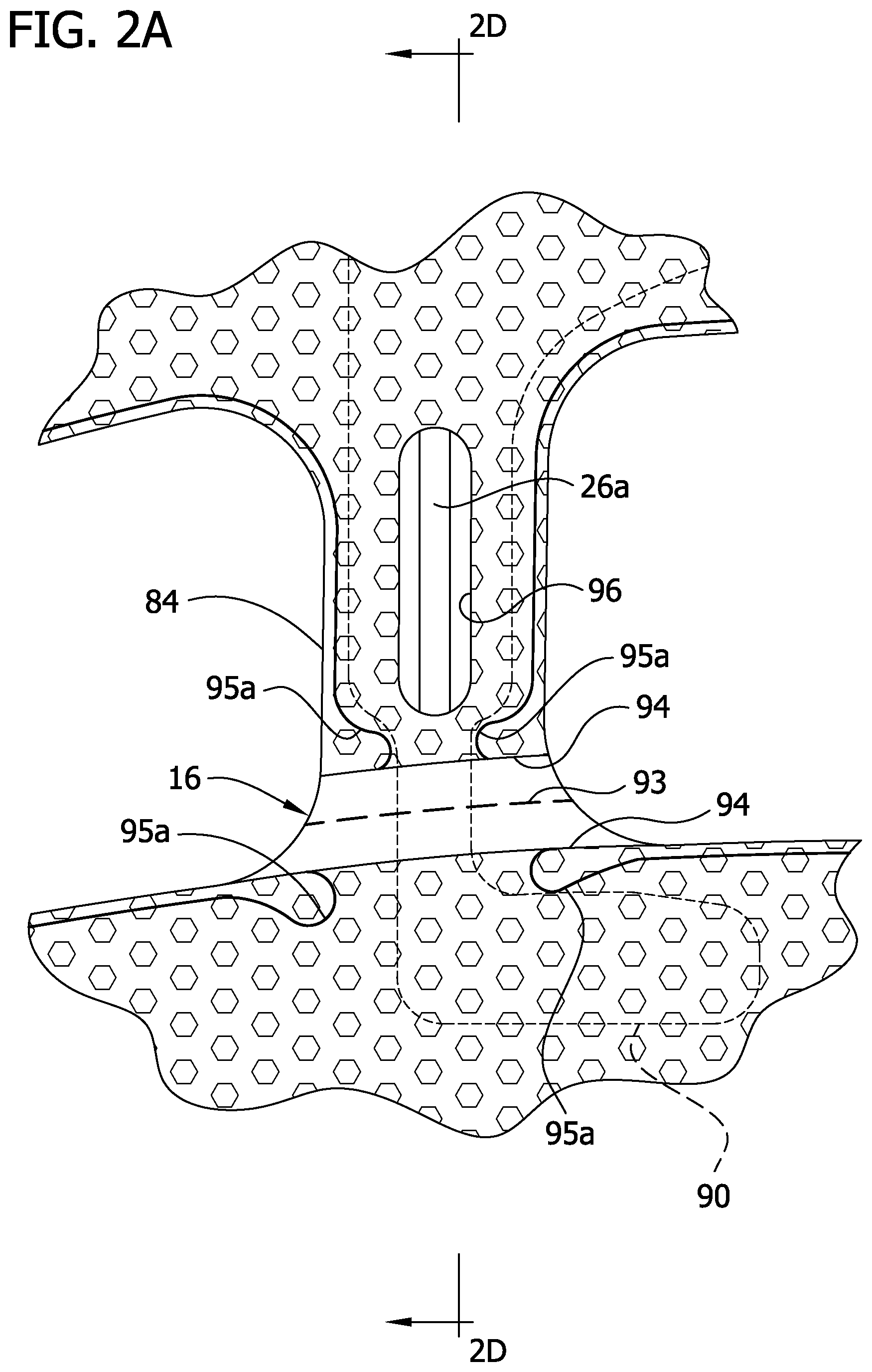
FIG. 2A is an enlarged, fragmentary view of FIG. 1 showing a perforation line extending across a left bridge of the compression sleeve;
FIG. 2B is similar to FIG. 2A with the perforation line comprising circular openings;
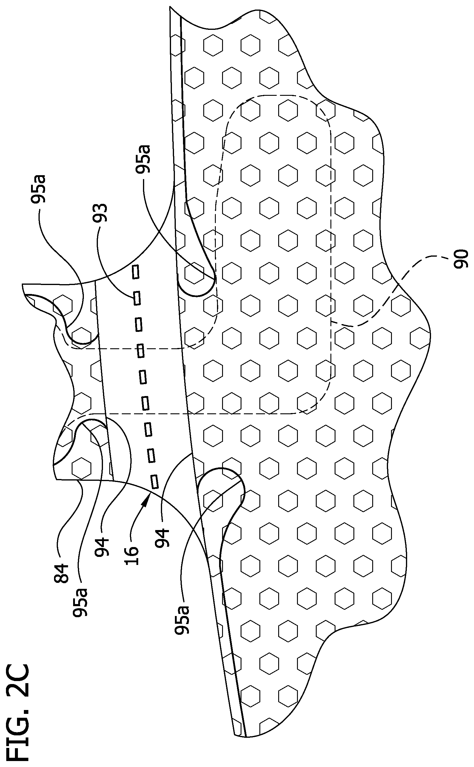
FIG. 2C is similar to FIG. 2A with the perforation line comprising slot-shaped openings;
FIG. 2D is a section taken in the plane including line 2D-2D in FIG. 2A;
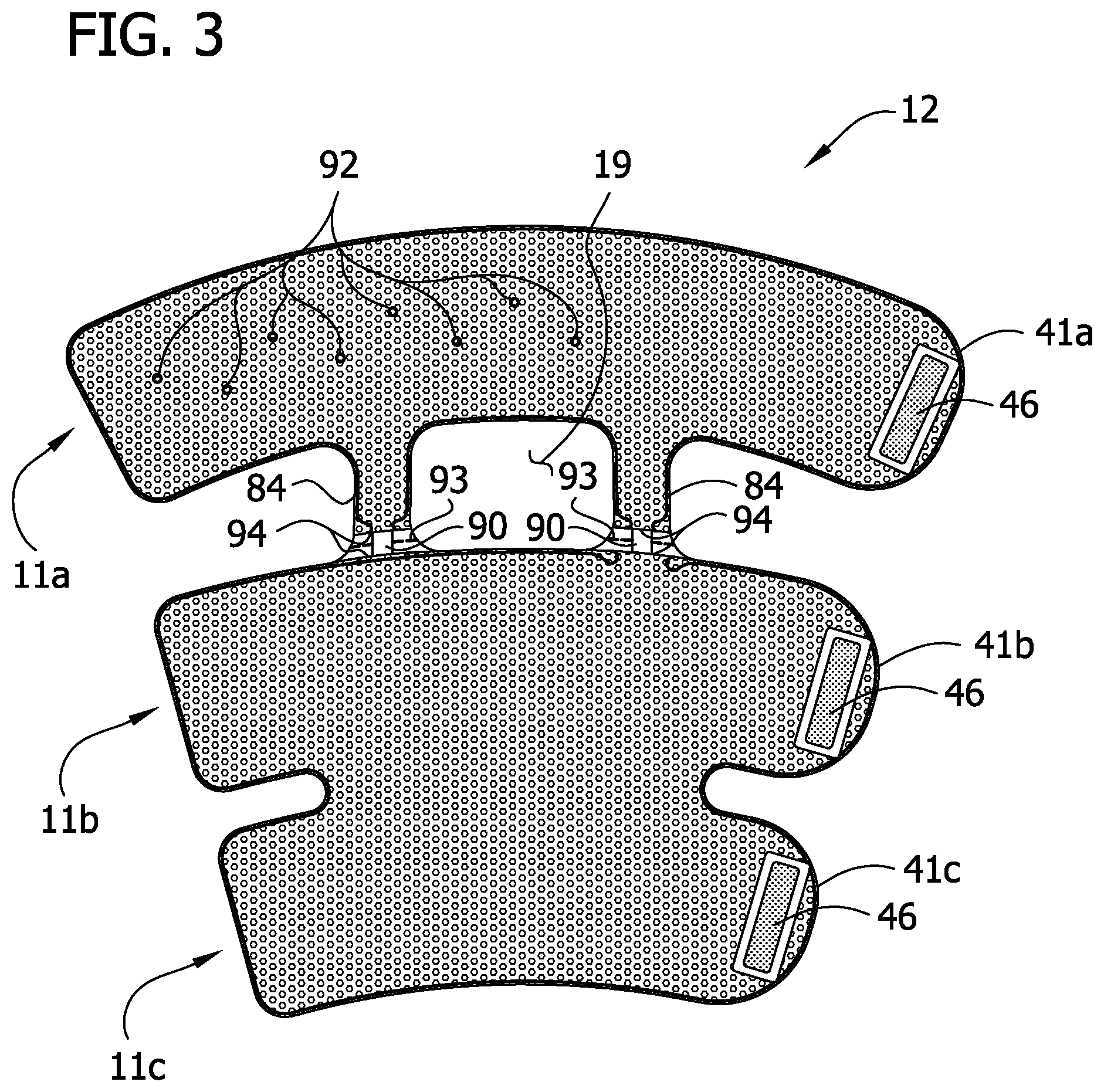
FIG. 3 is a rear elevation of the compression sleeve showing an inner layer;
FIG. 4 is an enlarged fragmentary elevation of an outer cover of the sleeve illustrating loop material;
FIG. 5 is a front elevation of the compression sleeve with the outer cover removed;
FIG. 6 is an enlarged perspective of a stay up insert of the compression sleeve;
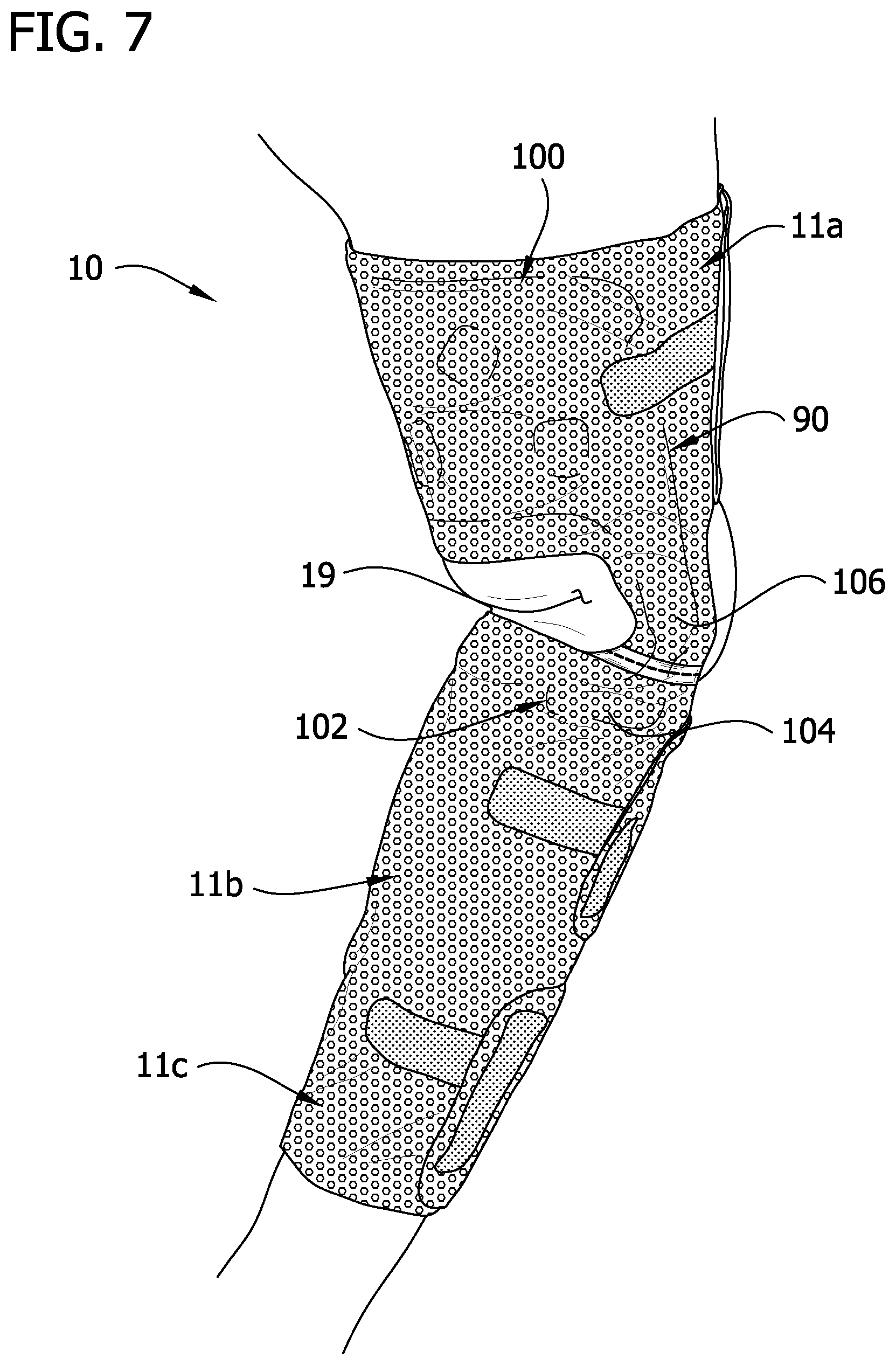
FIG. 7 is a perspective of the sleeve worn by a wearer illustrating interaction of the stay up insert with the wearer's leg;
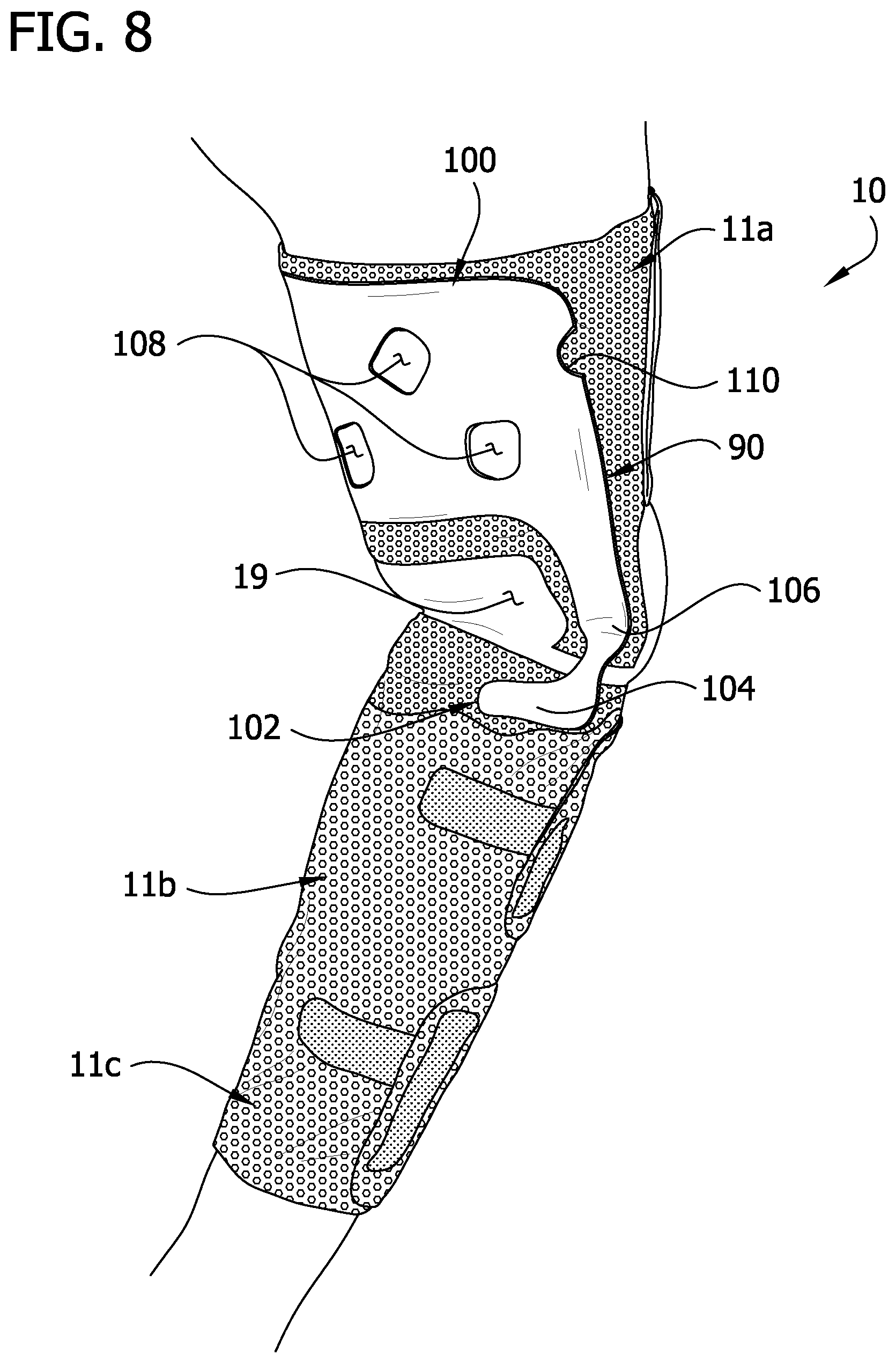
FIG. 8 is the perspective of FIG. 7 with portions of the sleeve partially removed to the stay up insert; and
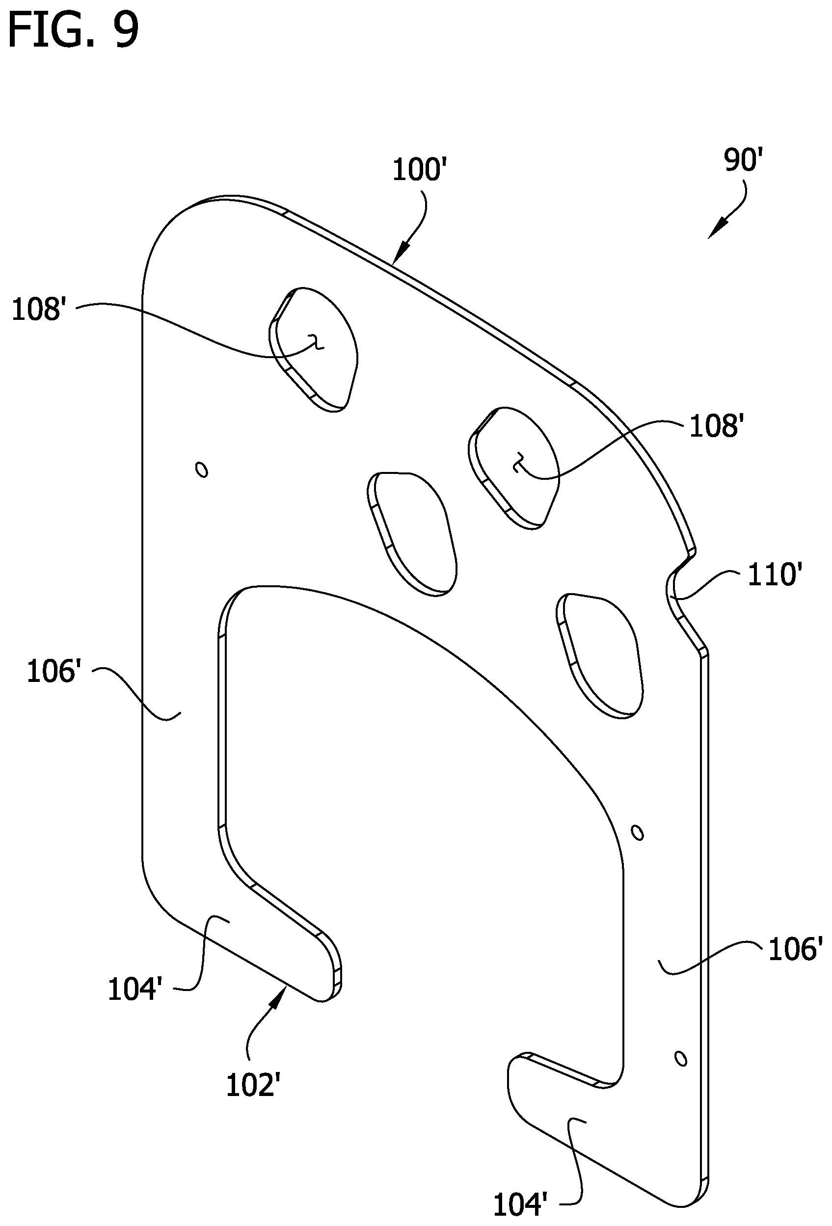
FIG. 9 is an enlarged perspective of a second embodiment of an insert of the compression sleeve.
Corresponding reference characters indicate corresponding parts throughout the drawings.
DESCRIPTION OF THE PREFERRED EMBODIMENTS
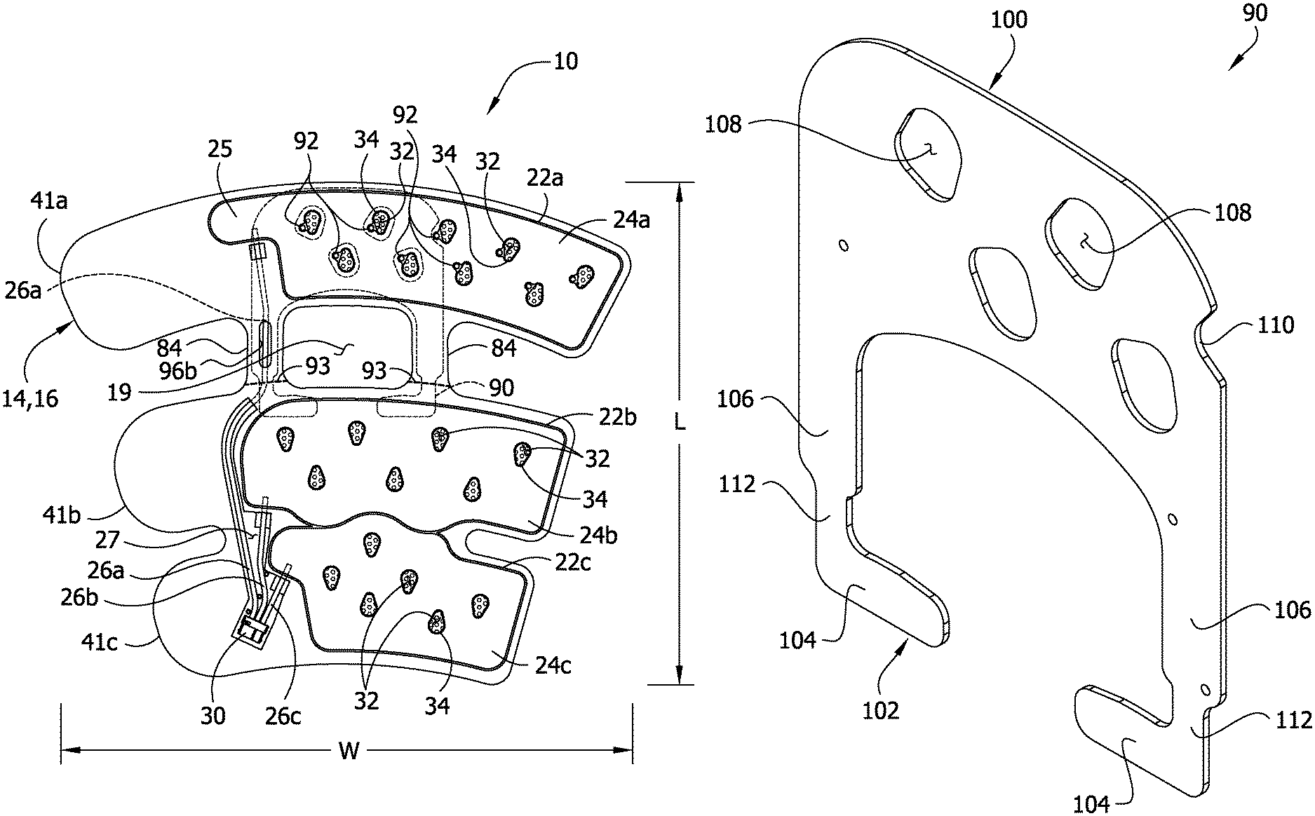
Referring now to the drawings, and in particular to FIGS. 1 and 2, one embodiment of a compression device (broadly, "a garment or a sleeve") for applying sequential compression therapy to a limb of a wearer is generally indicated at 10. The compression sleeve is of the type sized and shaped for being disposed around a leg of the wearer, but could be configured for application to other parts of the wearer's body. More specifically, the sleeve 10 has a width W (FIG. 1) for being wrapped around a full circumference of the leg and a length L (FIG. 1) for running from the ankle to a thigh of the leg. This type of sleeve is generally referred to in the art as a thigh-length sleeve including a thigh section 11a, a calf section 11b and an ankle section 11c. It is understood that other types of compression devices for being disposed about other limbs of the wearer's body are within the scope of the present invention.
Referring to FIGS. 1 and 2, the compression sleeve 10 comprises four layers secured together in the illustrated embodiment of the present invention. The scope of the present invention is not limited to four layers. More specifically, the compression sleeve comprises an inner layer, generally indicated at 12, on which a first intermediate layer (broadly, a first bladder layer), generally indicated at 14, is overlaid. A second intermediate layer (broadly, a second bladder layer), generally indicated at 16, overlies the first intermediate layer 14 and is secured thereto. An outer cover generally indicated at 18, overlies the second intermediate layer 16. In use, the inner layer 12 is disposed most adjacent to the limb of the wearer and is in contact with the limb of the wearer, and the outer cover 18 is most distant from the limb of the wearer. A knee opening 19 is formed through the sleeve 10 that is generally aligned with the back of the knee when the sleeve is applied to the leg. The layers have the same geometric shape and are superposed on each other so that edges of the layers generally coincide. The inner layer 12 and outer layer 18 may be secured to each other and/or to the intermediate layers 14, 16 in any suitable manner. It is contemplated that one or more of the layers 12, 14, 16, or 18 may not be superposed on a corresponding layer, but slightly offset to accommodate a particular feature of a patient's limb. Moreover, the number of sheets or thickness making up each layer 12, 14, 16, or 18 of the compression sleeve 10 may be other than described. The thickness of the layers may vary to add strength or to cause more expansion in one direction, such as toward the limb, during inflation.
Referring to FIGS. 1, 2 and 5, the first and second intermediate layers 14, 16, respectively, each include a single sheet of elastic material (broadly, "bladder material"). For example, the sheets 14 and 16 are made of a pliable PVC material as the bladder material. Layers 12 and 18 are made of a polyester material. The second intermediate layer 16 is secured to the first intermediate layer 14 via three separate bladder seam lines 22a, 22b, 22c defining a proximal bladder 24a, an intermediate bladder 24b and a distal bladder 24c, respectively, that are spaced apart longitudinally along the sleeve 10. The number of bladders may be other than three without departing from the scope of the present invention. As used herein, the terms "proximal", "distal", and "intermediate" represent relative locations of components, parts and the like of the compression sleeve when the sleeve is secured to the wearer's limb. As such, a "proximal" component or the like is disposed most adjacent to a point of attachment of the wearer's limb to the wearer's torso, a "distal" component is disposed most distant from the point of attachment, and an "intermediate" component is disposed generally anywhere between the proximal and distal components. Terms such as "proximal," "distal," "intermediate," "upper," "lower," "inner" and "outer" are used for convenience in describing relative locations but are not absolute requirements with respect to the environment as to the location of the various components.
For reasons discussed below, the proximal bladder 24a defines a proximal, lateral extension 25 near the upper edge margin of the sleeve 10 (see, FIG. 5). The bladders 24a, 24b, 24c are circumferential bladders meaning that they are sized and shaped to be wrapped around substantially the entire circumference of the wearer's limb or very nearly the entire circumference of the limb. For example, in one embodiment the bladders 24a, 24b, 24c each extend around at least 90% of a median circumference of a leg. It is to be understood that the circumferential extent may be other than described within the scope of the present invention
The intermediate layers 14, 16 may be secured together by radiofrequency welding, adhesive, or other chemical and/or mechanical process. It is understood that the intermediate layers 14, 16 may be secured together at other locations, such as around their peripheries and at bladder seam lines 22a, 22b, 22c to further define the shape of the inflatable bladders 24a, 24b, 24c. For purposes discussed below, the first intermediate layer 14 is secured to the inner layer 12 along a seam line 42 (FIG. 1) that runs along the outer periphery of the first intermediate layer 14 so that central regions of the bladders 24a, 24b, 24c are not secured to the inner layer 12. This permits the bladders 24a, 24b, 24c to move relative to the inner layer 12. The second intermediate layer 16 may also be secured to the inner layer 12 along the same seam line 42. The first intermediate layer 14 may be secured to the inner layer 12 by RF welding or adhesive or in other suitable ways. This structure improves comfort as described below.
Referring to FIGS. 2 and 4, each inflatable bladder 24a, 24b, 24c receives fluid from a source of compressed fluid (not shown) via a dedicated proximal bladder tube 26a, intermediate bladder tube 26b, and distal bladder tube 26c, respectively, (FIG. 2). A tube line need not be dedicated to a bladder to practice the invention. Each tube 26a, 26b, 26c is disposed between the intermediate layers 14, 16 and secured to the respective bladder 24a, 24b, 24c by the respective bladder seam line 22a, 22b, 22c. As shown best in FIGS. 2 and 4, the first intermediate layer 16 defines a cutout 27 (FIG. 2) so that portions of the tubes 26a, 26b, 26c are not disposed between the intermediate layers. Other ways of securing the tubes 26a, 26b, and 26c to the bladders 24a, 24b, and 24c are within the scope of the invention. The opposite ends of the tubes 26a, 26b, 26c are grouped together using a second connector 30 (FIGS. 1 and 2) that is adapted to fluidly connect the tubes to the source of compressed fluid. The source of compressed fluid may be an air compressor under the control of a microprocessor that sequentially pressurizes the bladders as is generally known in the art. An exemplary air compressor is described in U.S. Pat. No. 5,876,359 to Bock, the disclosure of which is incorporated herein by reference. The bladders 24a, 24b, 24c may be configured to contain air pressurized to at least about 10 mm Hg (1333 Pa) to about 45 mm Hg (6000 Pa). The bladders should be capable of being repeatedly pressurized without failure. Materials suitable for the sheets include, but are not limited to, flexible PVC material that will not stretch substantially. In another embodiment, the intermediate layers may form a chamber for receiving an inflatable bladder that is formed separate from the chamber. In this embodiment, the layers need not be capable of containing pressurized air as along as the inflatable bladders are so capable. It will be noted that the bladders 24a, 24b, 24c can have openings 32 extending completely through the bladders, as described in the embodiments of the present invention.
Referring particularly to FIGS. 1 and 5, the sleeve 10 defines a connecting section including a pair of bridge members 84 on opposite sides of the knee opening 19 that extend between and connect a proximal portion of the sleeve that includes the proximal bladder 24a to the remainder of the sleeve. The proximal tube 26a generally lies along an axis of bridge member 84 to help provide structural, lengthwise support to the sleeve 10. As shown best in FIG. 4, the cutout 27 in the intermediate sheet 16 does not extend through the bridge member 84. As explained above, the proximal bladder tube 26a is secured to the proximal bladder 24a at the proximal, lateral extension 25. The proximal bladder tube 26a runs along a side of a distal portion of the proximal bladder 24a so that it does not enter the bladder until it reaches the proximal, lateral extension 25. The proximal bladder tube 26a may provide support to the thigh section 11a against bunching or sliding down the leg, but need not do so in the illustrated embodiments.
Referring to FIGS. 1, 3 and 5, the proximal bladder 24a is secured to the inner layer 12 and the outer cover 18 at spot welds 92 adjacent to the bladder openings 32 and within an outer perimeter of the bladder defined by the bladder seamline 22a. The spot welds 92 maintain the outer cover 18 and the inner layer 12 in proper position with respect to the bladders 24a, 24b, 24c. In other words, the spot welds 92 prevent the bladders 24a, 24b, 24c from substantially shifting relative to the inner layer 12 and the outer cover 18 while still providing the sleeve 10 with substantial flexibility. Too much movement of inner layer 12 and the outer cover 18 with respect to the bladders 24a, 24b, 24c may reduce the fit of the sleeve, thereby leading to reduced efficacy of the compression therapy. The proximal bladder 24a is free from securement to the inner layer 12 and outer cover 18 other than at the spot welds 92 to maintain flexibility of the sleeve so that mobility of the patient's leg is not compromised. Inner layer 12 may be joined to layer 16 at the spot welds 92 or the inner layer 12 may be joined at the seam line 34 of the opening 32. Away from the openings 32 and spot welds 92, the inner layer 12 is not joined to surface of the bladder material forming the bladder that expands to provide compression treatment to the patient's limb.
Referring to FIGS. 1 and 4, the entirety of an outer surface of the outer cover 18 also acts as a fastening component of a fastening system for securing the sleeve 10 to the limb of the wearer. In a particular embodiment, the outer cover 18 of mesh (FIG. 4), for example, has an outer surface comprising loops 44 that acts as a loop component of a hook-and-loop fastening system. A mesh construction, as shown in FIG. 4, has interconnected or weaved fibers 21 of material forming the outer cover 18. The loops 44 may be formed as part of the material of the outer cover 18 or otherwise disposed on the surface of the outer cover. A suitable material with such construction is a polyester mesh loop 2103 sold by Quanzhou Fulian Warp Knitting Industrial Co., Ltd. of Quanzhou City, China. Hook components 46 (FIG. 3) are attached to an inner surface of the inner layer 12 at the proximal, intermediate and distal flaps 41a, 41b, 41c, respectively. The loops 44 of the outer cover 18 allow the hook components 46 (FIG. 3) to be secured anywhere along the outer surface of the outer cover when the sleeve 10 is wrapped circumferentially around the limb of the wearer. This allows for sleeve 10 to be of a substantially one-size-fits-all configuration with respect to the circumferences of different wearers' limbs. Moreover, the outer cover 18 having the loops 44 allows the practitioner to quickly and confidently secure the sleeve 10 to the wearer's limb without needing to align the fastening components.
Referring to FIGS. 2, 5 and 6, a stay up insert 90 (broadly, "a stay up device") is disposed between the first intermediate layer 14 and the inner layer 12. The insert 90 provides structural support to the sleeve 10 against buckling of the thigh section 11a in a vertical direction, and from sliding down the leg (e.g., as might otherwise be caused by buckling of the bridge members 84). The insert 90 comprises a first section 100, a second section 102 including first and second foot portions 104 and a bridge including first and second leg portions 106 connecting the first and second sections. The first section 100 is defined by a larger, roughly rectangular portion having rounded proximal corners. The first and second leg portions 104 each have a maximum width that is less than the width of either the first section 100 or the second section. Holes 108 in the first section 100 are generally aligned with the openings 32 in the proximal bladder 24a. An indent 110 in the first section 100 also provides clearance for an opening 32 in the proximal bladder 24a. The holes 108 and indent 110 are provided so that the insert 90 does not impede the evaporation function of the openings 32 in the intermediate layers 14, 16. Aligning the holes 108 with the openings 32 in the intermediate layers 14, 16 also fixes the insert 90 in place within the sleeve 10.
The leg portions 106 extend distally from the first section 100 and flank the knee opening 19. The bridge portions 106 include reduced width sections 112, the purpose of which will be explained hereinafter. The reduced width portions 112 have widths less than the maximum widths of the leg portions 106. The first and second foot portions 104 extend medially from the respective leg portion 106, below the knee opening 19. Free ends of the extension portions 104 are spaced apart. When the garment 10 is applied to the leg, the space overlies the popliteal vein. In this way, the insert 90 does not impede block flow of blood out of the leg through the popliteal vein. The insert 90 may be formed from pliable foam or any other suitable material for providing structural rigidity to the sleeve 10 to aid in keeping the sleeve in place on the limb of the wearer However, the foam is preferably also sufficiently pliable so that if in no way impedes wrapping the garment 10 around the leg.
Referring to FIGS. 7 and 8, the first section 100 of the insert 90 extends substantially the entire height of thigh section 11a of the sleeve 10. In this manner, the insert 90 provides support to the thigh section 11a to resist against bunching (buckling) of the thigh section or the tendency of the thigh section to slide down the limb. The leg portions 106 of the insert 90 extend along the length of the bridge members 84 of the sleeve 10 providing structural rigidity to the bridge members of the sleeve. The foot portions 104 are configured to engage a calf of the wearer causing the calf to serve as a shelf for supporting the proximal portion (thigh section 11a and bridge members 84) of the sleeve 10. Also, upon flexion of the leg, the calf will exert an upward force on the foot portions 104 providing an additional supporting force to keep the sleeve 10 in its intended position on the leg.
In a second embodiment, an insert 90' (FIG. 9) comprises a bridge having leg portions 106' having no reduced width sections. The insert 90' otherwise functions substantially the same as insert 90. Thus, the same parts will be designated with the same reference numeral as in the prior embodiment, but with the addition of a prime after the numeral.
In the illustrated embodiment, the thigh section 11a is removable from the remainder of the sleeve 10 to convert the sleeve from thigh length to knee length. In particular, the proximal portion of the sleeve 10 that includes the proximal bladder 24a and the bridge members 84 are removable from the remainder of the sleeve. Tear lines comprising perforation lines 93 in the intermediate layers 14, 16, extend transversely across the intermediate layers adjacent to where the bridge members 84 join thigh section 11a to the calf and ankle sections 11b, 11 c. In a preferred embodiment, the removal is destructive and permanent. It is understood that the sleeve may include one tear line or more than two tear lines within the scope of the invention. It is also understood that the shapes of the perforations may be circular (FIG. 2B) or slot-shaped (FIG. 2C) or other shapes within the scope of the invention. Other ways of weakening the sleeve 10 at the tear lines besides the perforation lines 93 are within the scope of the present invention. For example, the tear lines may include a thinned out portion of the intermediate layers 14, 16. It is also understood that the tear lines may be positioned to disconnect different ones of the sleeve sections (i.e., besides the thigh section 11a).
Neither the inner liner 12 nor the outer cover 18 have lines of weakness (e.g., perforations), although such a configuration is contemplated and within the scope of the present invention. Instead, as shown best in FIGS. 2A and 2D, both the inner liner 12 and the outer cover 18 are discontinuous generally adjacent to the perforation lines 93 in the intermediate layers 14, 16 so as to define respective opposing terminal edge margins 94 adjacent to the perforation lines. Each perforation line 93 is disposed between respective opposing terminal edge margins 94 of the inner liner 12 and the outer cover 18. In the illustrated embodiment, the terminal edge margins 94 of the inner liner 12 and the outer cover 18 are at least partially welded or otherwise secured to respective intermediate layers 14, 16 along terminal securement lines 95a associated with the respective left and right bridge members 84. The weld lines 95a are contiguous with the seamline 42 securing the bladder layers 14, 16 to the inner liner 12 and outer cover 18.
The terminal securement lines 95a on the bridge member 84 (FIGS. 2A-2C) are discontinuous and do not extend laterally across the bridge member. Instead, the terminal securement lines 95a converge toward each other and the center of the bridge 84. The terminal securement lines 95a, then turn back and curve down to the end of the terminal edge margins 94. On the left bridge member, the securement lines 95a define opposed inwardly projections on opposite sides of the bladder tube 26a and facilitate location of the bladder tube. However, the weld lines 95a do not permanently join the bladder tube 26a so that it can be removed, as described hereinafter. The reduced width sections 112 of the insert 90 are aligned with the terminal securement lines 95a where they converge and provide space for this convergence.
Generally, each terminal edge margin 94 is connected to the intermediate layers 14, 16 on a respective opposite side of the perforation line 93. By making the inner liner 12 and the outer cover 18 discontinuous at locations adjacent to the perforation lines 93 in the intermediate layers 14, 16, the sleeve is more easily torn at the perforation lines than if the inner liner and the outer cover were continuous and included perforation lines like the perforation lines in the intermediate layers. Moreover, the sleeve's resistance to tearing is greater at the terminal securement lines 95a. This greater tear resistance at the terminal securement lines 95a, facilitates more precise tearing of the sleeve along the perforation lines 93 and prevents incidental, significant deviation from the tear lines.
It is understood that the tear lines may be in other locations other than illustrated for removing the thigh section 11a from the remainder of the sleeve 10. As illustrated, the calf and ankle sections 11b, 11c do not have tear lines between them. It is also understood that the sleeve 10 may be configured to have other removable portions in addition to or instead of the thigh section 11a within the scope of the present invention.
As described previously, the proximal bladder tube 26a is disposed between the intermediate layers 14, 16 and extends through one of the bridge members 84. The proximal bladder tube 26a is releasably secured to the connector 30 so that the proximal bladder tube can be disconnected from the connector and so that the thigh section 11a can be removed from the remainder of the sleeve 10. The connector 30 and the proximal bladder tube 26a may be of the type disclosed in pending U.S. patent application Ser. No. 10/784,607, filed Feb. 23, 2004 and assigned to the assignee of the present application, the entirety of which is herein incorporated by reference. In particular, the connector 30 permits non-destructive disconnection of the proximal bladder tube 26a in preparation for removing the thigh section 11a. Because the proximal bladder tube 26a and leg portions 106 of the insert 90 extend through the bridge members 84 generally transverse to the tear line, it may be difficult to tear the sleeve 10 along the corresponding perforation lines in the intermediate layers 14, 16. Accordingly, a tube access opening or window 96 is formed by an opening 96a in the outer cover 18 and an aligned opening 96b in the second intermediate layer 16. Because the window extends through the outer cover 18 and the second intermediate layer 16 adjacent to the outer cover to expose a portion of the proximal bladder tube to facilitate removal of the proximal bladder tube 26a from the bridge member 84 before tearing the sleeve 10. In the illustrated embodiment, the tube access window 96 is generally oblong and extends less than the full axial length of one of the bridge members 84.
In use, the proximal bladder tube 26a can be disconnected from the connector 30 and then pulled through the tube access window 96 so that the tube no longer extends past the tear line between the intermediate layers 14, 16. With the tube 26a removed from between the intermediate layers 14, 16 at the corresponding tear line, the sleeve can be easily torn along the perforation lines 93 to remove the proximal portion, including the proximal bladder 24a, and the bridge members 84.
Similarly, as shown in the first embodiment of the insert 90, the leg portions 106 have the reduced width section 112 which makes it easier to pull the leg portions 106 and foot portions 104 from the knee section 11b of the sleeve 10. In addition to accommodating the terminal securement lines 95a, the reduced width portion 112 reduces the amount of material of the insert 90 at and below the bridge members 84. This construction makes it easier to remove the leg portions 106 and foot portions 104, from the knee section 11b of the sleeve 10. Thus, if the thigh section 11a and bridge members 84 are removed from the garment 10, the perforations 93 (see, FIG. 2a) are torn part way. The reduced width section 12 and extensions 104 are pulled out from the calf section 11b, and tearing of the perforation 93 is completed to separate the thigh section 11a and bridge members 84 from the remainder of the garment 10. Other ways of achieving separation are contemplated. For example, the leg portions of an insert (not shown) may have lines of weakness (e.g., perforations) that generally align with the perforations 93. In that instance, the extensions and part of the reduced width sections would be torn away from the remainder of the insert.
Having described the invention in detail, it will be apparent that modifications and variations are possible without departing from the scope of the invention defined in the appended claims.
When introducing elements of the present invention or the preferred embodiments(s) thereof, the articles "a", "an", "the" and "said" are intended to mean that there are one or more of the elements. The terms "comprising", "including" and "having" are intended to be inclusive and mean that there may be additional elements other than the listed elements.
In view of the above, it will be seen that the several objects of the invention are achieved and other advantageous results attained.
As various changes could be made in the above constructions without departing from the scope of the invention, it is intended that all matter contained in the above description and shown in the accompanying drawings shall be interpreted as illustrative and not in a limiting sense.
* * * * *
D00000
D00001
D00002
D00003
D00004
D00005
D00006
D00007
D00008
D00009
D00010
D00011
D00012
D00013
XML
uspto.report is an independent third-party trademark research tool that is not affiliated, endorsed, or sponsored by the United States Patent and Trademark Office (USPTO) or any other governmental organization. The information provided by uspto.report is based on publicly available data at the time of writing and is intended for informational purposes only.
While we strive to provide accurate and up-to-date information, we do not guarantee the accuracy, completeness, reliability, or suitability of the information displayed on this site. The use of this site is at your own risk. Any reliance you place on such information is therefore strictly at your own risk.
All official trademark data, including owner information, should be verified by visiting the official USPTO website at www.uspto.gov. This site is not intended to replace professional legal advice and should not be used as a substitute for consulting with a legal professional who is knowledgeable about trademark law.