Exchangeable working channel
Jenkins
U.S. patent number 10,716,461 [Application Number 15/975,653] was granted by the patent office on 2020-07-21 for exchangeable working channel. This patent grant is currently assigned to Auris Health, Inc.. The grantee listed for this patent is Auris Health, Inc.. Invention is credited to Thomas R. Jenkins.


| United States Patent | 10,716,461 |
| Jenkins | July 21, 2020 |
Exchangeable working channel
Abstract
The systems, methods, and apparatus disclosed herein are directed to an exchangeable working channel for a surgical instrument comprising a proximal portion, a distal portion, and an instrument channel configured to receive the exchangeable working channel. The exchangeable working channel may comprise a shaft comprising a proximal region and a distal region; an inner surface defining a lumen extending through the shaft; and an outer surface configured to interface with the instrument channel of the surgical instrument. The exchangeable working channel may further comprise one or more locking members configured to releasably couple to the proximal portion or the distal portion of the surgical instrument. The exchangeable working channel may increase a service life of the surgical instrument as a worn working channel can be exchanged with a new one.
| Inventors: | Jenkins; Thomas R. (Alameda, CA) | ||||||||||
|---|---|---|---|---|---|---|---|---|---|---|---|
| Applicant: |
|
||||||||||
| Assignee: | Auris Health, Inc. (Redwood
City, CA) |
||||||||||
| Family ID: | 64269723 | ||||||||||
| Appl. No.: | 15/975,653 | ||||||||||
| Filed: | May 9, 2018 |
Prior Publication Data
| Document Identifier | Publication Date | |
|---|---|---|
| US 20180333044 A1 | Nov 22, 2018 | |
Related U.S. Patent Documents
| Application Number | Filing Date | Patent Number | Issue Date | ||
|---|---|---|---|---|---|
| 62507709 | May 17, 2017 | ||||
| Current U.S. Class: | 1/1 |
| Current CPC Class: | A61B 1/018 (20130101); A61B 1/00105 (20130101); A61B 1/00128 (20130101); A61B 1/00059 (20130101); G02B 23/2476 (20130101); A61B 1/121 (20130101) |
| Current International Class: | A61B 1/00 (20060101); A61B 1/018 (20060101); G02B 23/24 (20060101); A61B 1/12 (20060101) |
| Field of Search: | ;600/121-125,127,129 |
References Cited [Referenced By]
U.S. Patent Documents
| 3572325 | March 1971 | Bazell et al. |
| 3913565 | October 1975 | Kawahara |
| 4294234 | October 1981 | Matsuo |
| 4392485 | July 1983 | Hiltebrandt |
| 4607619 | August 1986 | Seike |
| 4690175 | September 1987 | Ouchi et al. |
| 4706656 | November 1987 | Kuboto |
| 4741326 | May 1988 | Sidall |
| 4745908 | May 1988 | Wardle |
| 4748969 | June 1988 | Wardle |
| 4750475 | June 1988 | Yoshihashi |
| 4771766 | September 1988 | Aoshiro |
| 4846791 | July 1989 | Hattler |
| 4869238 | September 1989 | Opie et al. |
| 4906496 | March 1990 | Hosono |
| 4907168 | March 1990 | Boggs |
| 4967732 | November 1990 | Inoue |
| 5050585 | September 1991 | Takahashi |
| 5083549 | January 1992 | Cho et al. |
| 5106387 | April 1992 | Kittrell et al. |
| 5108800 | April 1992 | Koo |
| 5125909 | June 1992 | Heimberger |
| 5168864 | December 1992 | Shockey |
| 5217002 | June 1993 | Katsurada |
| 5251611 | October 1993 | Zehel |
| 5257617 | November 1993 | Takahashi |
| 5261391 | November 1993 | Inoue |
| 5287861 | February 1994 | Wilk |
| 5313934 | May 1994 | Wiita et al. |
| 5386818 | February 1995 | Schneebaum |
| 5448988 | September 1995 | Watanabe |
| 5478330 | December 1995 | Imran et al. |
| 5482029 | January 1996 | Sekiguchi |
| 5489270 | February 1996 | van Erp |
| 5507725 | April 1996 | Savage et al. |
| 5533985 | July 1996 | Wang |
| 5580200 | December 1996 | Fullerton |
| 5681296 | October 1997 | Ishida |
| 5704534 | January 1998 | Huitema et al. |
| 5720775 | February 1998 | Lamard |
| 5741429 | April 1998 | Donadio, III |
| 5749889 | May 1998 | Bacich |
| 5873817 | February 1999 | Kokish et al. |
| 5876325 | March 1999 | Mizuno et al. |
| 5879287 | March 1999 | Yoshihashi |
| 5882347 | March 1999 | Mouris-Laan |
| 5888191 | March 1999 | Akiba |
| 5910129 | June 1999 | Koblish et al. |
| 5938586 | August 1999 | Wilk |
| 6012494 | January 2000 | Balazs |
| 6143013 | November 2000 | Samson et al. |
| 6157853 | December 2000 | Blume et al. |
| 6197015 | March 2001 | Wilson |
| 6198974 | March 2001 | Webster, Jr. |
| 6315715 | November 2001 | Taylor et al. |
| 6404497 | June 2002 | Backman |
| 6436107 | August 2002 | Wang et al. |
| 6464632 | October 2002 | Taylor |
| 6485411 | November 2002 | Konstorum |
| 6491626 | December 2002 | Stone et al. |
| 6537205 | March 2003 | Smith |
| 6554793 | April 2003 | Pauker et al. |
| 6716178 | April 2004 | Kilpatrick et al. |
| 6746422 | June 2004 | Noriega |
| 6749560 | June 2004 | Konstorum |
| 6790173 | September 2004 | Saadat |
| 6827710 | December 2004 | Mooney |
| 6827712 | December 2004 | Tovey et al. |
| 6837846 | January 2005 | Jaffe |
| 6908428 | June 2005 | Aizenfeld |
| 6921362 | July 2005 | Ouchi |
| 6958035 | October 2005 | Friedman |
| 7008401 | March 2006 | Thompson et al. |
| 7130700 | October 2006 | Gardeski et al. |
| 7594903 | September 2009 | Webler et al. |
| 7645230 | January 2010 | Mikkaichi |
| 7645231 | January 2010 | Akiba |
| 7789827 | September 2010 | Landry |
| 7930065 | April 2011 | Larkin et al. |
| 8052636 | November 2011 | Moll et al. |
| 8246536 | August 2012 | Ochi |
| 8444637 | May 2013 | Podmore et al. |
| 8498691 | July 2013 | Moll et al. |
| 8515215 | August 2013 | Younge et al. |
| 8652030 | February 2014 | Matsuura et al. |
| 8758231 | June 2014 | Bunch et al. |
| 8827947 | September 2014 | Bosman et al. |
| 9186046 | November 2015 | Ramamurthy et al. |
| 9427551 | August 2016 | Leeflang et al. |
| 9504604 | November 2016 | Alvarez |
| 9561083 | February 2017 | Yu et al. |
| 9591990 | March 2017 | Chen et al. |
| 9622827 | April 2017 | Yu et al. |
| 9636184 | May 2017 | Lee et al. |
| 9713509 | July 2017 | Schuh et al. |
| 9727963 | August 2017 | Mintz et al. |
| 9737371 | August 2017 | Romo et al. |
| 9737373 | August 2017 | Schuh |
| 9744335 | August 2017 | Jiang |
| 9763741 | September 2017 | Alvarez et al. |
| 9788910 | October 2017 | Schuh |
| 9818681 | November 2017 | Machida |
| 9844353 | December 2017 | Walker et al. |
| 9844412 | December 2017 | Bogusky et al. |
| 9867635 | January 2018 | Alvarez et al. |
| 9918681 | March 2018 | Wallace et al. |
| 9931025 | April 2018 | Graetzel et al. |
| 9949749 | April 2018 | Noonan et al. |
| 9955986 | May 2018 | Shah |
| 9962228 | May 2018 | Schuh et al. |
| 10016900 | July 2018 | Meyer et al. |
| 10022192 | July 2018 | Ummalaneni |
| 10130427 | November 2018 | Tanner et al. |
| 10145747 | December 2018 | Lin et al. |
| 10159532 | December 2018 | Ummalaneni et al. |
| 2001/0004676 | June 2001 | Ouchi |
| 2003/0036748 | February 2003 | Cooper et al. |
| 2003/0130564 | July 2003 | Martone |
| 2003/0158545 | August 2003 | Hovda et al. |
| 2003/0163199 | August 2003 | Chu et al. |
| 2003/0195664 | October 2003 | Nowlin et al. |
| 2004/0015122 | January 2004 | Zhang et al. |
| 2004/0054322 | March 2004 | Vargas |
| 2004/0138525 | July 2004 | Saadat et al. |
| 2004/0193013 | September 2004 | Isakawa et al. |
| 2004/0249246 | December 2004 | Campos |
| 2005/0004515 | January 2005 | Hart et al. |
| 2005/0125005 | June 2005 | Fujikura |
| 2005/0154262 | July 2005 | Banik et al. |
| 2005/0159646 | July 2005 | Nordstrom et al. |
| 2005/0222581 | October 2005 | Fischer, Jr. |
| 2005/0272975 | December 2005 | McWeeney et al. |
| 2005/0273085 | December 2005 | Hinman et al. |
| 2005/0288549 | December 2005 | Mathis |
| 2006/0041188 | February 2006 | Dirusso et al. |
| 2006/0111692 | May 2006 | Hlavka et al. |
| 2006/0241368 | October 2006 | Fichtinger et al. |
| 2006/0264708 | November 2006 | Horne |
| 2006/0276827 | December 2006 | Mitelberg et al. |
| 2007/0060879 | March 2007 | Weitzner et al. |
| 2007/0112355 | May 2007 | Salahieh |
| 2007/0135733 | June 2007 | Soukup et al. |
| 2007/0135763 | June 2007 | Musbach et al. |
| 2007/0135803 | June 2007 | Belson |
| 2007/0156019 | July 2007 | Larkin et al. |
| 2007/0270645 | November 2007 | Ikeda |
| 2007/0270679 | November 2007 | Nguyen et al. |
| 2007/0282167 | December 2007 | Barenboym et al. |
| 2007/0287886 | December 2007 | Saadat |
| 2008/0039255 | February 2008 | Jinno et al. |
| 2008/0051629 | February 2008 | Sugiyama et al. |
| 2008/0065103 | March 2008 | Cooper et al. |
| 2008/0097293 | April 2008 | Chin et al. |
| 2008/0108869 | May 2008 | Sanders et al. |
| 2008/0139887 | June 2008 | Fitpatrick |
| 2008/0146874 | June 2008 | Chen |
| 2008/0177285 | July 2008 | Brock et al. |
| 2008/0208001 | August 2008 | Hadani |
| 2008/0212082 | September 2008 | Froggatt et al. |
| 2008/0218770 | September 2008 | Moll et al. |
| 2009/0099420 | April 2009 | Woodley et al. |
| 2009/0163851 | June 2009 | Holloway |
| 2009/0247880 | October 2009 | Naruse et al. |
| 2009/0254083 | October 2009 | Wallace et al. |
| 2009/0262109 | October 2009 | Markowitz et al. |
| 2009/0299344 | December 2009 | Lee et al. |
| 2009/0306587 | December 2009 | Milijasevic et al. |
| 2010/0030023 | February 2010 | Yoshie |
| 2010/0073150 | March 2010 | Olson et al. |
| 2010/0114115 | May 2010 | Schlesinger et al. |
| 2010/0130823 | May 2010 | Ando |
| 2010/0217184 | August 2010 | Koblish et al. |
| 2010/0249497 | September 2010 | Peine et al. |
| 2010/0249506 | September 2010 | Prisco et al. |
| 2011/0009863 | January 2011 | Stanislaw |
| 2011/0046441 | February 2011 | Wiltshire et al. |
| 2011/0077681 | March 2011 | Nagano |
| 2011/0098533 | April 2011 | Onoda |
| 2011/0130718 | June 2011 | Kidd et al. |
| 2011/0148442 | June 2011 | Berner |
| 2011/0152880 | June 2011 | Alvarez et al. |
| 2011/0261183 | October 2011 | Ma et al. |
| 2011/0306836 | December 2011 | Ohline et al. |
| 2012/0071894 | March 2012 | Tanner et al. |
| 2012/0071895 | March 2012 | Stahler et al. |
| 2012/0123327 | May 2012 | Miller |
| 2012/0136419 | May 2012 | Zarembo et al. |
| 2012/0143226 | June 2012 | Belson et al. |
| 2012/0190976 | July 2012 | Kleinstreuer |
| 2012/0191107 | July 2012 | Tanner et al. |
| 2012/0239012 | September 2012 | Laurent et al. |
| 2012/0259244 | October 2012 | Roberts et al. |
| 2012/0283747 | November 2012 | Popovic |
| 2013/0018400 | January 2013 | Milton et al. |
| 2013/0030519 | January 2013 | Tran et al. |
| 2013/0035537 | February 2013 | Wallace et al. |
| 2013/0090552 | April 2013 | Ramamurthy et al. |
| 2013/0109957 | May 2013 | Hooft et al. |
| 2013/0144116 | June 2013 | Cooper et al. |
| 2013/0165854 | June 2013 | Sandhu et al. |
| 2013/0165908 | June 2013 | Purdy et al. |
| 2013/0304091 | November 2013 | Straehnz |
| 2013/0317276 | November 2013 | D'Andrea |
| 2013/0317519 | November 2013 | Romo et al. |
| 2013/0345519 | December 2013 | Piskun et al. |
| 2014/0046313 | February 2014 | Pederson et al. |
| 2014/0142591 | May 2014 | Alvarez et al. |
| 2014/0200402 | July 2014 | Snoke |
| 2014/0276391 | September 2014 | Yu |
| 2014/0276594 | September 2014 | Tanner et al. |
| 2014/0309649 | October 2014 | Alvarez et al. |
| 2014/0316397 | October 2014 | Brown |
| 2014/0357984 | December 2014 | Wallace et al. |
| 2014/0364870 | December 2014 | Alvarez et al. |
| 2014/0379000 | December 2014 | Romo et al. |
| 2015/0031950 | January 2015 | Drontle |
| 2015/0051592 | February 2015 | Kintz |
| 2015/0101442 | April 2015 | Romo |
| 2015/0119638 | April 2015 | Yu et al. |
| 2015/0164594 | June 2015 | Romo et al. |
| 2015/0164596 | June 2015 | Romo |
| 2015/0335480 | November 2015 | Alvarez et al. |
| 2016/0001038 | January 2016 | Romo et al. |
| 2016/0007881 | January 2016 | Wong et al. |
| 2016/0067450 | March 2016 | Kowshik |
| 2016/0151122 | June 2016 | Alvarez et al. |
| 2016/0227982 | August 2016 | Takahashi |
| 2016/0270865 | September 2016 | Landey et al. |
| 2016/0287279 | October 2016 | Bovay et al. |
| 2016/0287346 | October 2016 | Hyodo et al. |
| 2016/0296294 | October 2016 | Moll et al. |
| 2016/0346049 | December 2016 | Allen et al. |
| 2016/0374541 | December 2016 | Agrawal et al. |
| 2016/0374590 | December 2016 | Wong et al. |
| 2017/0007337 | January 2017 | Dan |
| 2017/0065364 | March 2017 | Schuh et al. |
| 2017/0065365 | March 2017 | Schuh |
| 2017/0100199 | April 2017 | Yu et al. |
| 2017/0119413 | May 2017 | Romo |
| 2017/0119481 | May 2017 | Romo et al. |
| 2017/0165011 | June 2017 | Bovay et al. |
| 2017/0172673 | June 2017 | Yu et al. |
| 2017/0202627 | July 2017 | Sramek et al. |
| 2017/0209073 | July 2017 | Sramek et al. |
| 2017/0281218 | October 2017 | Timm |
| 2017/0290631 | October 2017 | Lee et al. |
| 2017/0333679 | November 2017 | Jiang |
| 2017/0340396 | November 2017 | Romo et al. |
| 2017/0365055 | December 2017 | Mintz et al. |
| 2017/0367782 | December 2017 | Schuh et al. |
| 2018/0025666 | January 2018 | Ho et al. |
| 2018/0055589 | March 2018 | Joseph et al. |
| 2018/0177383 | June 2018 | Noonan et al. |
| 2018/0177556 | June 2018 | Noonan et al. |
| 2018/0177561 | June 2018 | Mintz et al. |
| 2018/0214011 | August 2018 | Graetzel et al. |
| 2018/0221038 | August 2018 | Noonan et al. |
| 2018/0221039 | August 2018 | Shah |
| 2018/0250083 | September 2018 | Schuh et al. |
| 2018/0271616 | September 2018 | Schuh et al. |
| 2018/0279852 | October 2018 | Rafii-Tari et al. |
| 2018/0280660 | October 2018 | Landey et al. |
| 2018/0289243 | October 2018 | Landey et al. |
| 2018/0289431 | October 2018 | Draper et al. |
| 2018/0325499 | November 2018 | Landey et al. |
| 2018/0333044 | November 2018 | Jenkins |
| 2018/0360435 | December 2018 | Romo |
| 2019/0000559 | January 2019 | Berman et al. |
| 2019/0000560 | January 2019 | Berman et al. |
| 2019/0000566 | January 2019 | Graetzel et al. |
| 2019/0000568 | January 2019 | Connolly et al. |
| 2019/0000576 | January 2019 | Mintz et al. |
| 2019/0083183 | March 2019 | Moll et al. |
| 2019/0105110 | April 2019 | Tanner et al. |
| 2019/0105776 | April 2019 | Ho et al. |
| 2019/0105785 | April 2019 | Meyer |
| 2019/0107454 | April 2019 | Lin |
| 2019/0110839 | April 2019 | Rafii-Tari et al. |
| 2019/0110843 | April 2019 | Ummalaneni et al. |
| 2019/0151148 | April 2019 | Alvarez et al. |
| 2019/0228528 | April 2019 | Mintz et al. |
| 2019/0167366 | June 2019 | Ummalaneni |
| 2019/0175009 | June 2019 | Mintz |
| 2019/0175062 | June 2019 | Rafii-Tari et al. |
| 2019/0175287 | June 2019 | Hill |
| 2019/0175799 | June 2019 | Hsu |
| 2019/0183585 | June 2019 | Rafii-Tari et al. |
| 2019/0183587 | June 2019 | Rafii-Tari et al. |
| 2019/0216548 | July 2019 | Ummalaneni |
| 2019/0216550 | July 2019 | Eyre |
| 2019/0216576 | July 2019 | Eyre |
| 2019/0223974 | July 2019 | Romo |
| 2019/0228525 | July 2019 | Mintz et al. |
| 2019/0246882 | August 2019 | Graetzel et al. |
| 2019/0262086 | August 2019 | Connolly et al. |
| 2019/0269468 | September 2019 | Hsu et al. |
| 2019/0274764 | September 2019 | Romo |
| 2019/0290109 | September 2019 | Agrawal et al. |
| 2019/0298160 | October 2019 | Ummalaneni et al. |
| 2019/0298458 | October 2019 | Srinivasan |
| 2019/0298460 | October 2019 | Al-Jadda |
| 2019/0298465 | October 2019 | Chin |
| 2019/0307987 | October 2019 | Yu |
| 2019/0328213 | October 2019 | Landey et al. |
| 2019/0336238 | November 2019 | Yu |
| 2019/0365209 | December 2019 | Ye et al. |
| 2019/0365479 | December 2019 | Rafii-Tari |
| 2019/0365486 | December 2019 | Srinivasan et al. |
| 2019/0374297 | December 2019 | Wallace et al. |
| 2019/0375383 | December 2019 | Alvarez |
| 2019/0380787 | December 2019 | Ye |
| 2019/0380797 | December 2019 | Yu |
| 2020/0000530 | January 2020 | DeFonzo |
| 2020/0000533 | January 2020 | Schuh |
| 2020/0022767 | January 2020 | Hill |
| 2020/0038128 | February 2020 | Joseph |
| 2020/0039086 | February 2020 | Meyer |
| 2020/0046434 | February 2020 | Graetzel |
| 2020/0046942 | February 2020 | Alvarez |
| 2020/0054405 | February 2020 | Schuh |
| 2020/0054408 | February 2020 | Schuh et al. |
| 2020/0060516 | February 2020 | Baez |
| 101500470 | Aug 2009 | CN | |||
| 102665590 | Sep 2012 | CN | |||
| 0 543 539 | May 1993 | EP | |||
| 0 776 739 | Jun 1997 | EP | |||
| 1 442 720 | Aug 2004 | EP | |||
| 0 904 796 | Nov 2004 | EP | |||
| 2006-525087 | Nov 2006 | JP | |||
| 2007-511247 | May 2007 | JP | |||
| 2010-046384 | Mar 2010 | JP | |||
| 2011-015992 | Jan 2011 | JP | |||
| 2012-105793 | Jun 2012 | JP | |||
| WO 94/14494 | Jul 1994 | WO | |||
| WO 00/67640 | Nov 2000 | WO | |||
| WO 02/074178 | Sep 2002 | WO | |||
| WO 04/039273 | May 2004 | WO | |||
| WO 04/105849 | Dec 2004 | WO | |||
| WO 05/032637 | Apr 2005 | WO | |||
| WO 05/081202 | Sep 2005 | WO | |||
| WO 09/097461 | Jun 2007 | WO | |||
| WO 07/146987 | Dec 2007 | WO | |||
| WO 08/097540 | Aug 2008 | WO | |||
| WO 09/092059 | Jul 2009 | WO | |||
| WO 10/081187 | Jul 2010 | WO | |||
| WO 10/088187 | Aug 2010 | WO | |||
| WO 11/005335 | Jan 2011 | WO | |||
| WO 13/107468 | Jul 2013 | WO | |||
| WO 15/093602 | Dec 2013 | WO | |||
| WO 16/003052 | Jan 2016 | WO | |||
Other References
|
International Search Report and Written Opinion dated Aug. 8, 2018 in application No. PCT/US18/31850. cited by applicant. |
Primary Examiner: Kasztejna; Matthew J
Attorney, Agent or Firm: Knobbe, Martens, Olson & Bear, LLP
Parent Case Text
CROSS-REFERENCE TO RELATED APPLICATION
This application claims the benefit of U.S. Provisional Application No. 62/507,709, filed May 17, 2017, which is hereby incorporated by reference in its entirety.
Claims
What is claimed is:
1. A removable working channel of a surgical instrument, the surgical instrument extending from a proximal end to a distal end and having a working channel sheath configured to receive the removable working channel, the removable working channel comprising: a shaft, comprising: a proximal region and a distal region, the distal region of the shaft being located proximal relative to the distal end of the surgical instrument when the removable working channel is received within the working channel sheath; an inner surface defining a lumen extending through the shaft, wherein the inner surface is configured to allow passage of a medical tool through the shaft to extend outward beyond the distal end of the surgical instrument; and an outer surface having a substantially circular cross-section and configured to interface with the working channel sheath of the surgical instrument, wherein a diameter of the outer surface of the shaft is substantially the same as a diameter of an inner surface of the working channel sheath; and a first locking member comprising a luer fit or a threaded fit component, the first locking member at the proximal region of the shaft, the first locking member configured to releasably couple to the proximal end of the surgical instrument.
2. The removable working channel of claim 1, wherein the surgical instrument comprises an endoscope.
3. The removable working channel of claim 1, further comprising a second locking member at the distal region of the shaft.
4. The removable working channel of claim 3, wherein the second locking member comprises an annular ring or a spring clamp at the distal region of the shaft.
5. The removable working channel of claim 3, wherein the second locking member comprises at least one of a clamp, a friction fit component, a latch, a snap fit component, a screw lock, a luer fit, a threaded fit component, a slip fit component, a bayonet, a ball spring or pogo latch, a detent, a magnet, and an O-ring component.
6. The removable working channel of claim 1, wherein the removable working channel does not comprise a locking member at the distal region of the shaft.
7. The removable working channel of claim 1, further comprising at least one identification member configured to store data comprising information regarding a source of the removable working channel.
8. The removable working channel of claim 7, wherein the at least one identification member comprises a radio-frequency identification (RFID) tag.
9. The removable working channel of claim 1, wherein the shaft is made of extruded plastic.
10. The removable working channel of claim 1, wherein the shaft further comprises an inner liner attached to the inner surface of the removable working channel.
11. The removable working channel of claim 10, wherein the inner liner is made of polytetrafluoroethylene (PTFE), high-density polyethylene (HDPE), low-density polyethylene (LDPE), linear low density poly ethylene (LLDPE), or hydrophilic materials.
12. The removable working channel of claim 1, wherein the shaft comprises a reinforcement member disposed at least partially between the inner surface of the removable working channel and the outer surface of the removable working channel.
13. The removable working channel of claim 12, wherein the reinforcement member comprises at least one of (i) one or more coils, (ii) one or more braids, and (iii) one cable tube.
14. The removable working channel of claim 1, wherein the shaft is parallel to a longitudinal axis of the surgical instrument when the removable working channel is received within the working channel sheath.
15. A surgical instrument configured to receive a removable working channel, the surgical instrument comprising: a proximal end and a distal end; an instrument channel extending through the proximal and distal end, the instrument channel comprising: a proximal region and a distal region; and a first inner surface defining a lumen extending through the instrument channel; a working channel sheath attached to the first inner surface of the instrument channel and configured to interface with the removable working channel; and a first coupling member comprising a luer fit or a threaded fit component, the first coupling member at the proximal end of the surgical instrument, the first coupling member configured to releasably couple to a proximal region of the removable working channel, the removable working channel further including a distal region located proximal relative to the distal end of the surgical instrument when the removable working channel is received within the working channel sheath, wherein the removable working channel comprises a second inner surface configured to allow passage of a medical tool through the instrument channel to extend outward beyond the distal end of the surgical instrument when the removable working channel is received within the working channel sheath, and wherein an outer surface of the removable working channel has a substantially circular cross-section and a diameter that is substantially the same as a diameter of the first inner surface.
16. The surgical instrument of claim 15, further comprising a second coupling member at the distal end of the surgical instrument, the second coupling member configured to releasably couple to the distal region of the removable working channel.
17. The removable working channel of claim 15, wherein the working channel sheath is made of extruded plastic.
18. The surgical instrument of claim 15, wherein the working channel sheath comprises an inner liner made of polytetrafluoroethylene (PTFE), high-density polyethylene (HDPE), low-density polyethylene (LDPE), or linear low density poly ethylene (LLDPE).
19. The surgical instrument of claim 15, wherein the working channel sheath comprises at least one of (i) one or more coils, (ii) one or more braids, and (iii) one cable tube.
20. The surgical instrument of claim 15, wherein the coils, the braids, or the cable tubes are at least partially made of stainless steel, copper, other metals, Nitinol alloy, graphite, polyparaphenylene terephthalamide, Ultra-high-molecular-weight polyethylene (UHMWPE), PEEK, or nylon.
21. The surgical instrument of claim 15, further comprising at least one detector configured to read data from at least one identification member of the removable working channel, the data comprising information regarding a source of the removable working channel.
Description
TECHNICAL FIELD
The present disclosure relates generally to medical devices, and more particularly to an exchangeable working channel for a surgical and/or medical instrument.
BACKGROUND
Medical procedures may involve manipulation of a tool positioned remotely from the operator. For example, the tool may be advanced through a working channel of a surgical instrument (e.g., catheters, endoscopes, etc.) through which the tool is inserted into the body of a patient. In one example, the surgical instrument may be used in the context of minimally invasive surgery, during which medical tools may be inserted into a patient's body through an incision or orifice to access and/or treat tissue. In another example, the surgical instrument may be used in procedures such as biopsies and endoscopy. The surgical instrument may comprise an interior lumen (e.g., a working channel) providing a pathway to the tissue site. Catheters and various tools, such as, for example, a grasping forcep, a biopsy forcep, a cytology brush, a balloon dilator, a snare, a needle, and/or a basket, can be inserted through the working channel of the surgical instrument to access the tissue site.
SUMMARY
The systems, methods and devices of this disclosure each have several innovative aspects, no single one of which is solely responsible for the desirable attributes disclosed herein.
One aspect relates to a removable working channel of a surgical instrument, the surgical instrument having a proximal portion, a distal portion, and a working channel sheath configured to receive the removable working channel, the removable working channel comprising: a shaft, comprising: a proximal region and a distal region; an inner surface defining a lumen extending through the shaft; and an outer surface configured to interface with the working channel sheath of the surgical instrument; and a first locking member at the proximal region of the shaft, the first locking member configured to releasably couple to the proximal portion of the surgical instrument. In some implementations, the surgical instrument may comprise an endoscope.
In some implementations, the first locking member comprises at least one of a clamp, a friction fit component, a latch, a snap fit component, a screw lock, a luer fit, a threaded fit component, a slip fit component, a bayonet, a ball spring or pogo latch, a detent, a magnet, and an O-ring component.
Some implementations further comprise a second locking member at the distal region of the shaft, the second locking member configured to releasably couple to the distal portion of the surgical instrument. In some implementations, the second locking member comprises an annular ring or a spring clamp at the distal region of the shaft. In some implementations, the second locking member comprises at least one of a clamp, a friction fit component, a latch, a snap fit component, a screw lock, a luer fit, a threaded fit component, a slip fit component, a bayonet, a ball spring or pogo latch, a detent, a magnet, and an O-ring component. In some implementations, the removable working channel does not comprise a locking member at the distal region of the shaft.
In some implementations, the first locking member comprises a locking component configured to engage with a tool; and the first locking member is configured to be releasable from the proximal portion of the surgical instrument when, in use, the tool engages and actuates the locking component of the first locking member.
Some implementations further comprise at least one identification member configured to store data comprising information regarding a source of the removable working channel. In some implementations, the at least one identification member comprises a radio-frequency identification (RFID) tag.
In some implementations, the shaft is made of extruded plastic. In some implementations, the shaft is made of at least one of polyether block amide (PEBA), Nylon, polytetrafluoroethylene (PTFE), high-density polyethylene (HDPE), low-density polyethylene (LDPE), linear low density poly ethylene (LLDPE), polyvinyl chloride (PVC), polystyrene, acrylonitrile butadiene styrene (ABS), polypropylene (PP), thermoplastic elastomers (TPE), fluorinated ethylene propylene (FEP), acetal copolymer, polysulfone, polyetheretherketone (PEEK), polyetherimide, polyphenylene oxide (PPO), perfluoroalkoxy (PFA) plastic, polyvinylidene fluoride (PVDF), ethylene tetrafluoroethylene (ETFE), ethylene chlorotrifluoroethylene (ECTFE), and tetrafluoroethylene/hexafluoropropylene/vinylidene fluoride (THV) copolymer. In some implementations, the shaft further comprises an inner liner attached to the inner surface. In some implementations, the inner liner is made of PTFE, HDPE, LDPE, LLDPE, or hydrophilic materials.
In some implementations, the shaft comprises a reinforcement member disposed at least partially between the inner surface and the outer surface. In some implementations, the reinforcement member comprises at least one of (i) one or more coils, (ii) one or more braids, and (iii) one cable tube.
In some implementations, an outer diameter of the shaft is greater than or equal to about 1.2 mm and less than or equal to about 6 mm. In some implementations, an outer diameter of the shaft is about 3.2 mm.
Another aspect relates to an surgical instrument configured to receive a removable working channel, the surgical instrument comprising: a proximal portion and a distal portion; an instrument channel extending through the proximal and distal portions, the instrument channel comprising: a proximal region and a distal region; and an inner surface defining a lumen extending through the instrument channel; a working channel sheath attached to the inner surface of the instrument channel and configured to interface with the removable working channel; and a first coupling member at the proximal portion of the surgical instrument, the first coupling member configured to releasably couple to a proximal region of the removable working channel.
Some implementations further comprise a second coupling member at the distal portion of the surgical instrument, the second coupling member configured to releasably couple to a distal region of the removable working channel. In some implementations, the working channel sheath is made of extruded plastic. In some implementations, the working channel sheath is made of PEBA, Nylon, PTFE, HDPE, LDPE, LLDPE, PVC, polystyrene, ABS, PP, TPE, FEP, acetal copolymer, polysulfone, PEEK, PPO, PFA plastic, PVDF, ETFE, ECTFE, and THV copolymer. In some implementations, the working channel sheath comprises an inner liner made of PTFE, HDPE, LDPE, or LLDPE.
In some implementations, the working channel sheath comprises at least one of (i) one or more coils, (ii) one or more braids, and (iii) one cable tube. In some implementations, the coils, the braids, or the cable tubes are at least partially made of stainless steel, copper, other metals, Nitinol alloy, graphite, polyparaphenylene terephthalamide, Ultra-high-molecular-weight polyethylene (UHMWPE), PEEK, or nylon.
Some implementations further comprises at least one detector configured to read data from at least one identification member of the removable working channel, the data comprising information regarding a source of the removable working channel.
Yet another aspect relates to a tool configured to adjust an attachment between a removable working channel and a surgical instrument, the removable working channel having proximal and distal regions, the surgical instrument having proximal and distal portions, the tool comprising: an actuator configured to engage and actuate at least one of (i) one or more locking members at the proximal region of the removable working channel and (ii) one or more coupling members at the proximal portion of the surgical instrument, wherein, in use, the engagement and actuation of the at least one of (i) one or more locking members and (ii) one or more coupling members by the actuator facilitates at least one of locking and unlocking the attachment between the removable working channel and the surgical instrument.
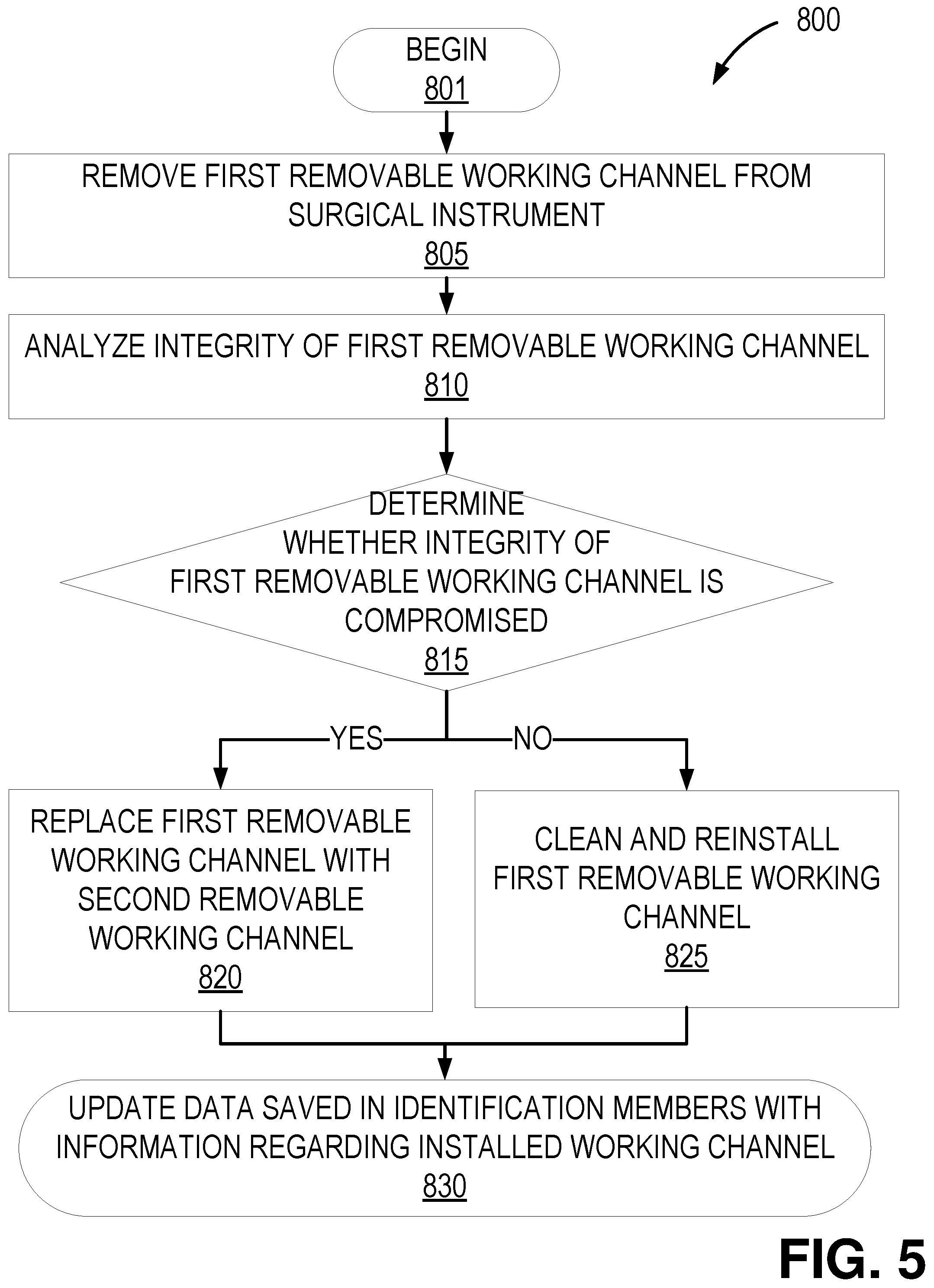
Still another aspect relates to a method for sanitizing one or more removable working channels of a surgical instrument, the method comprising: removing a first removable working channel from the surgical instrument; analyzing an integrity of the first removable working channel; cleaning and reinstalling the first removable working channel in an instrument channel of the surgical instrument in response to the integrity of the first removable working channel being uncompromised; and replacing the first removable working channel with a second removable working channel in the instrument channel in response to the integrity of the first removable working channel being compromised.
In some implementations, the one or more removable working channels further comprise at least one identification member configured to store data comprising information regarding a source of the one or more removable working channels. In some implementations, the at least one identification member comprises a radio-frequency identification (RFID) tag. Some implementations further comprise updating the identification member with data regarding whether the first removable working channel or the second removable working channel is installed in the instrument channel of the surgical instrument. In some implementations, the one or more removable working channels are made of extruded plastic.
In some implementations, removing the first removable working channel from the surgical instrument comprises removing the first removable working channel through a proximal end of the instrument. In some implementations, replacing the first removable working channel with the second removable working channel comprises inserting a distal end of the second removable working channel through a proximal end of the instrument channel until the distal end of the second removable working channel reaches near a distal end of the instrument channel.
In some implementations, the surgical instrument comprises: a proximal portion and a distal portion; an instrument channel extending through the proximal and distal portions; a working channel sheath attached to an inner surface of the instrument channel; and one or more coupling members at the proximal portion or the distal portion of the surgical instrument.
In some implementations, the one or more coupling members comprise at least one of a clamp, a friction fit component, a latch, a snap fit component, a screw lock, a luer fit, a threaded fit component, a slip fit component, a bayonet, a ball spring or pogo latch, a detent, a magnet, and an O-ring component. In some implementations, the surgical instrument comprises an endoscope.
In some implementations, the one or more removable working channels further comprise one or more locking members configured to releasably couple to the one or more coupling members of the surgical instrument.
In some implementations, removing the first removable working channel from the surgical instrument comprises: engaging a tool to at least one of (i) the one or more coupling members of the surgical instrument and (ii) the one or more locking members of the first removable working channel; actuating the tool to release the one or more coupling members of the surgical instrument from the one or more locking members of the first removable working channel; and removing the first removable working channel from the surgical instrument.
In some implementations, replacing the first removable working channel with a second removable working channel comprises inserting a distal end of the second removable working channel through a proximal end of the instrument channel until at least one of the one or more coupling members of the surgical instrument engage with at least one of the one or more locking members of the second removable working channel.
BRIEF DESCRIPTION OF THE DRAWINGS
The disclosed aspects will hereinafter be described in conjunction with the appended drawings and appendices, provided to illustrate and not to limit the disclosed aspects, wherein like designations denote like elements.
FIGS. 1A-1E illustrate an embodiment of a surgical instrument including a removable working channel in accordance with one or more aspects as described herein.
FIGS. 2A-2B illustrate another embodiment of a surgical instrument including a removable working channel in accordance with one or more aspects as described herein.
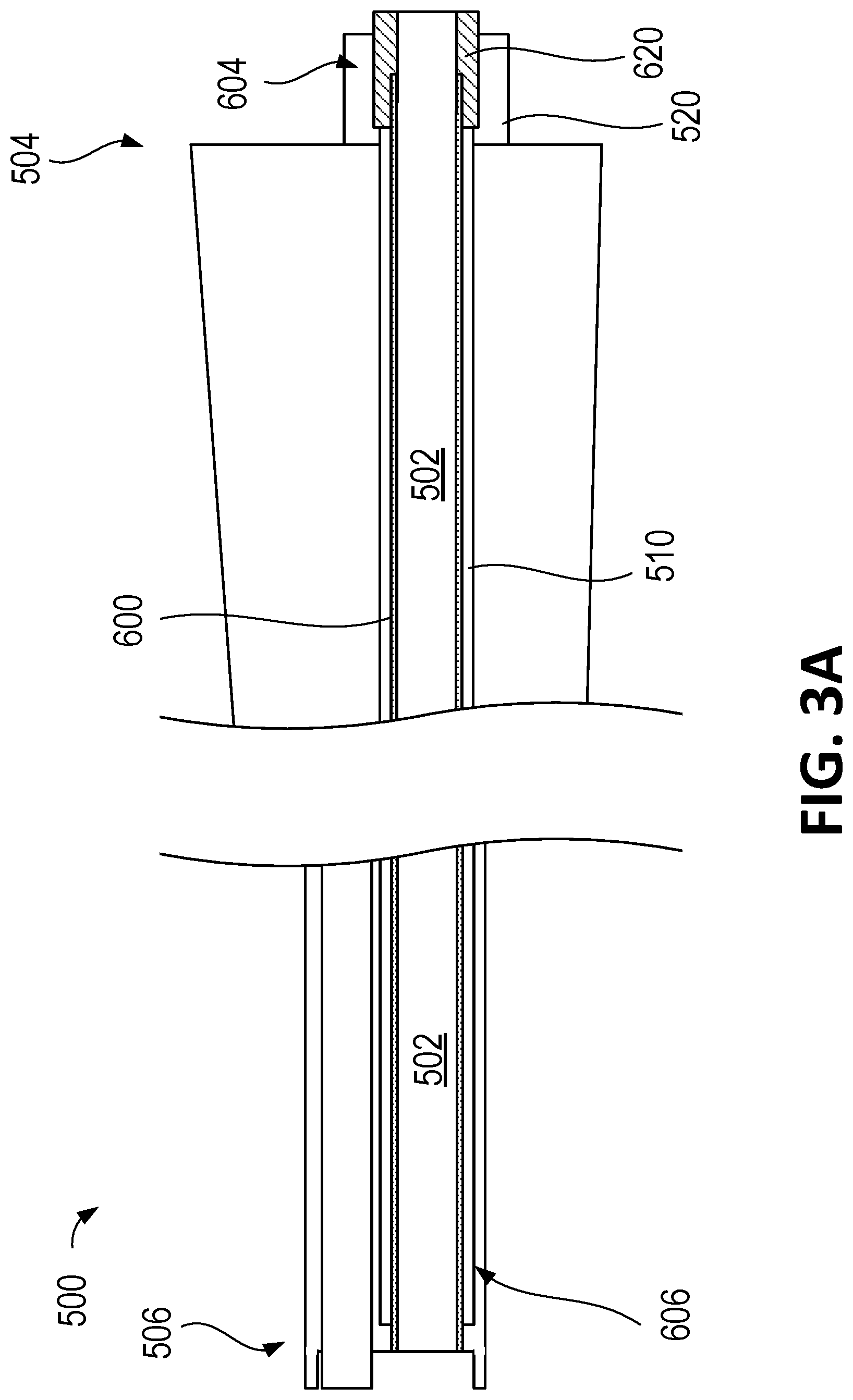
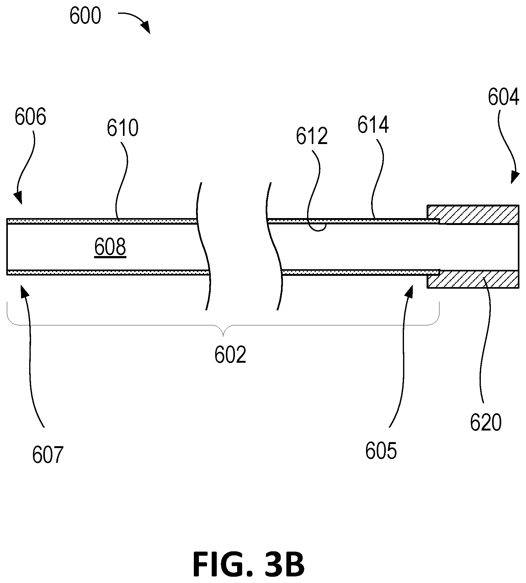
FIGS. 3A-3B illustrate another embodiment of a surgical instrument including a removable working channel in accordance with one or more aspects as described herein.
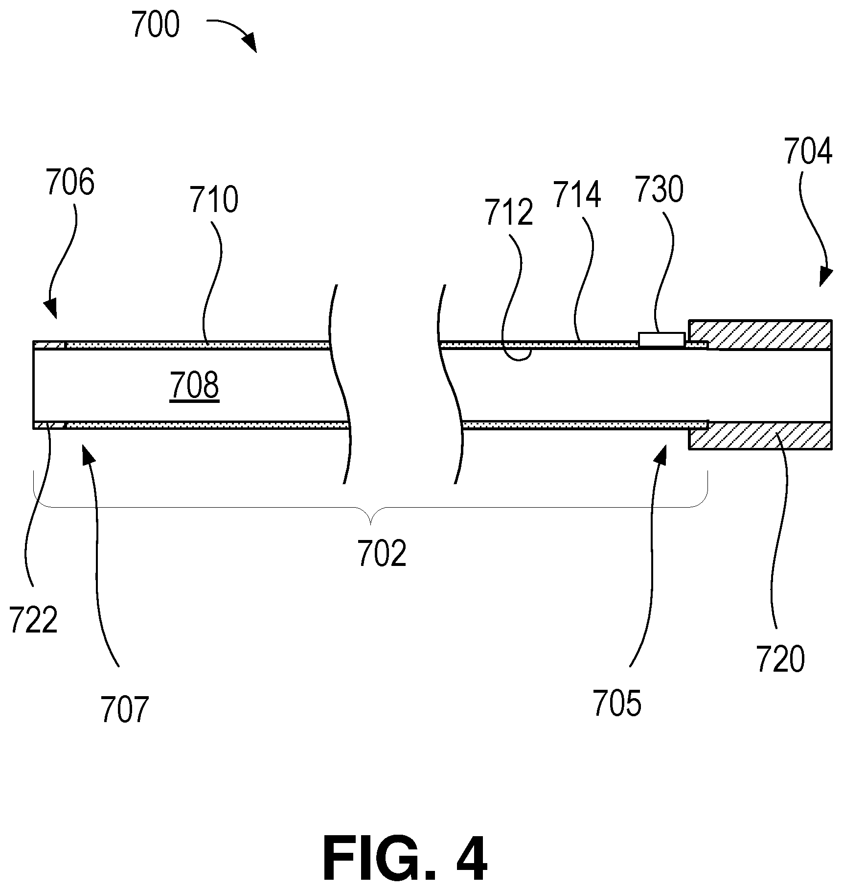
FIG. 4 illustrates another embodiment of a removable working channel in accordance with one or more aspects as described herein.
FIG. 5 illustrates a flowchart of an example methodology of replacing and/or cleaning a removable working channel of a surgical instrument.
DETAILED DESCRIPTION
Introduction
During a medical procedure (e.g., minimally invasive surgery) using a surgical instrument (e.g., a catheter, endoscope, laparoscope, etc.) comprising an instrument channel, medical tools, such as, for example, cannulas, graspers, forceps, scissors, retractors, and/or stabilizers may be inserted through the instrument channel of the surgical instrument to reach a target organ or tissue. Components of these medical tools may be made of, for example, stainless steel, tungsten, other metals, or other rigid materials. As a result, when a medical tool passes through the instrument channel of the surgical instrument, the medical tool may scratch, deform, or otherwise damage the inner surface of the instrument channel. Over repeated uses of the surgical instrument, interaction between the medical tools and the inner surface of the instrument channel can result in wear and tear of the inner surface of the instrument channel. Thus, in some cases, the service life of the surgical instrument may be limited by the service life of the instrument channel of the surgical instrument.
The present disclosure relates to removable working channel(s) that may be installed or removed from the instrument channel of the surgical instrument. The removable working channel may be configured to be installed inside the instrument channel of the surgical instrument and to at least partially cover the inner surface of the instrument channel. When the removable working channel is worn enough to warrant replacement, the worn working channel can be exchanged with a new working channel. Thus, the disclosed removable working channel can provide an improved service life of the surgical instrument.
The disclosed systems and apparatuses can provide advantages for medical procedures and applications, including but not limited to surgeries that involve the use of endoscopic, laparoscopic, and/or catheter-delivered tools. Thus, though the disclosed removable working channels are described in portions of the present disclosure below within the context of endoscopy, it should be understood that such removable working channels can also be used with other surgical instruments and in other types of procedures in order to provide the disclosed benefits. For example, a removable working channel as described herein can be used in other types of instruments including but not limited to a bronchoscope, a sinuscope (e.g., as used in sinusplasty), a nasopharyngoscope, a laryngoscope, a laparoscope, a gastroscope, a colonoscope, a hysteroscope, a cystoscope, a uroscope, a urethroscope, a cardioscope (e.g., as used in heart catheterization), and an arthroscope, and more generally in procedures that involve delivering tools through flexible and/or curved scopes, catheters, or tubes (collectively referred to as endoscopes, for simplicity of describing the various embodiments discussed herein).
As used herein, "distal" refers to a relative position or location a scope, instrument, or tool that is positioned closer to the patient during use, and "proximal" refers to a relative position or location of the scope, instrument, or tool positioned closer to the operator (e.g., a physician or robotic control system). Stated differently, the relative positions of components of the scope, instrument, tool, and/or the robotic system are described herein from the vantage point of the operator, going from a proximal location to a distal location.
As used herein, the terms "about" or "approximately" refer to a range of measurements of a length, thickness, a quantity, time period, or other measurable values. Such range of measurements encompasses variations of +/-10% or less, preferably +/-5% or less, more preferably +/-1% or less, and still more preferably +/-0.1% or less, of and from the specified value, in so far as such variations are appropriate in order to function in the disclosed devices, systems, and techniques.
Various embodiments will be described below in conjunction with the drawings for purposes of illustration. It should be appreciated that many other implementations of the disclosed concepts are possible, and various advantages can be achieved with the disclosed implementations. Headings are included herein for reference and to aid in locating various sections. These headings are not intended to limit the scope of the concepts described with respect thereto. Such concepts may have applicability throughout the entire specification.
Example Surgical Instrument and Removable Working Channel
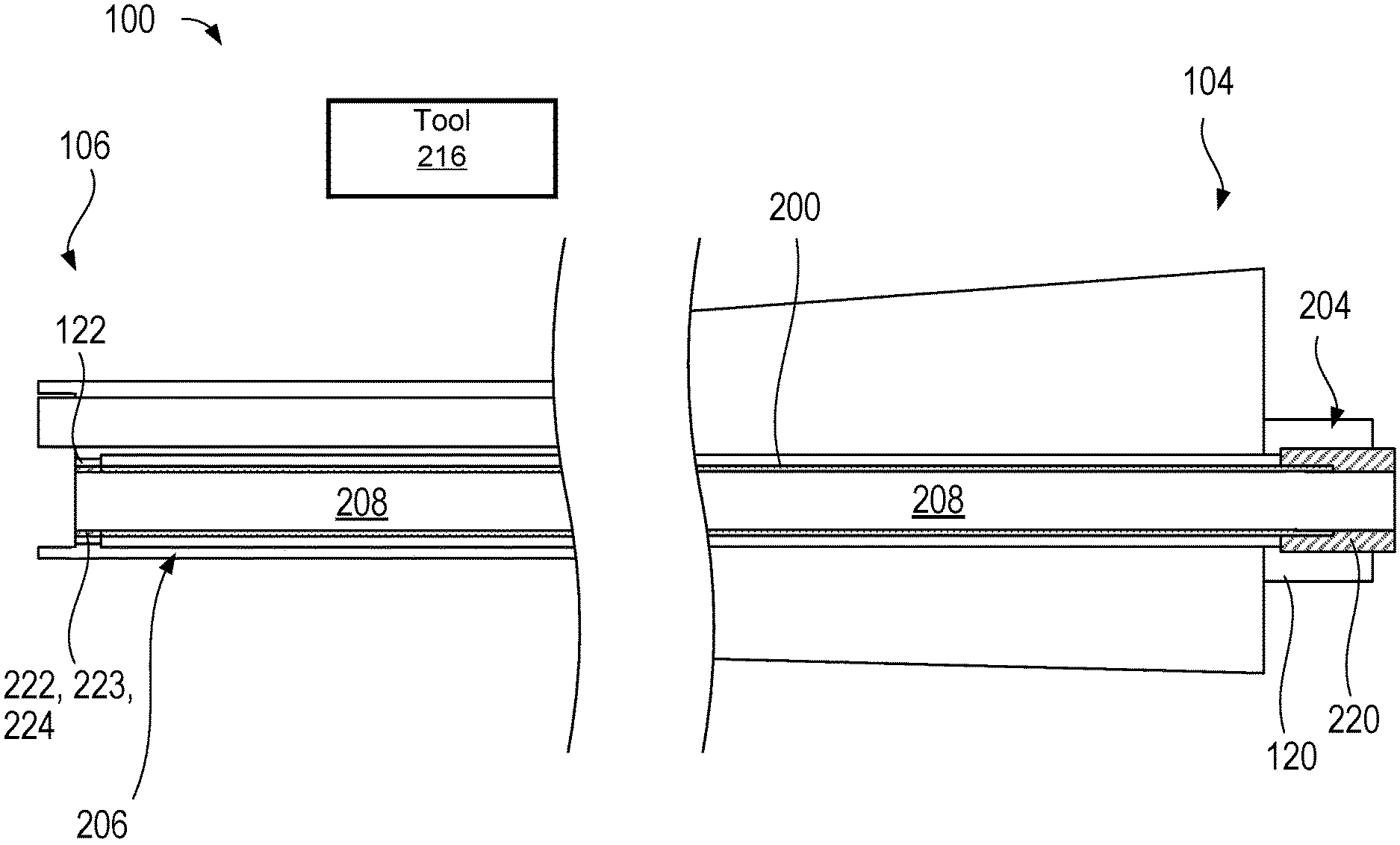
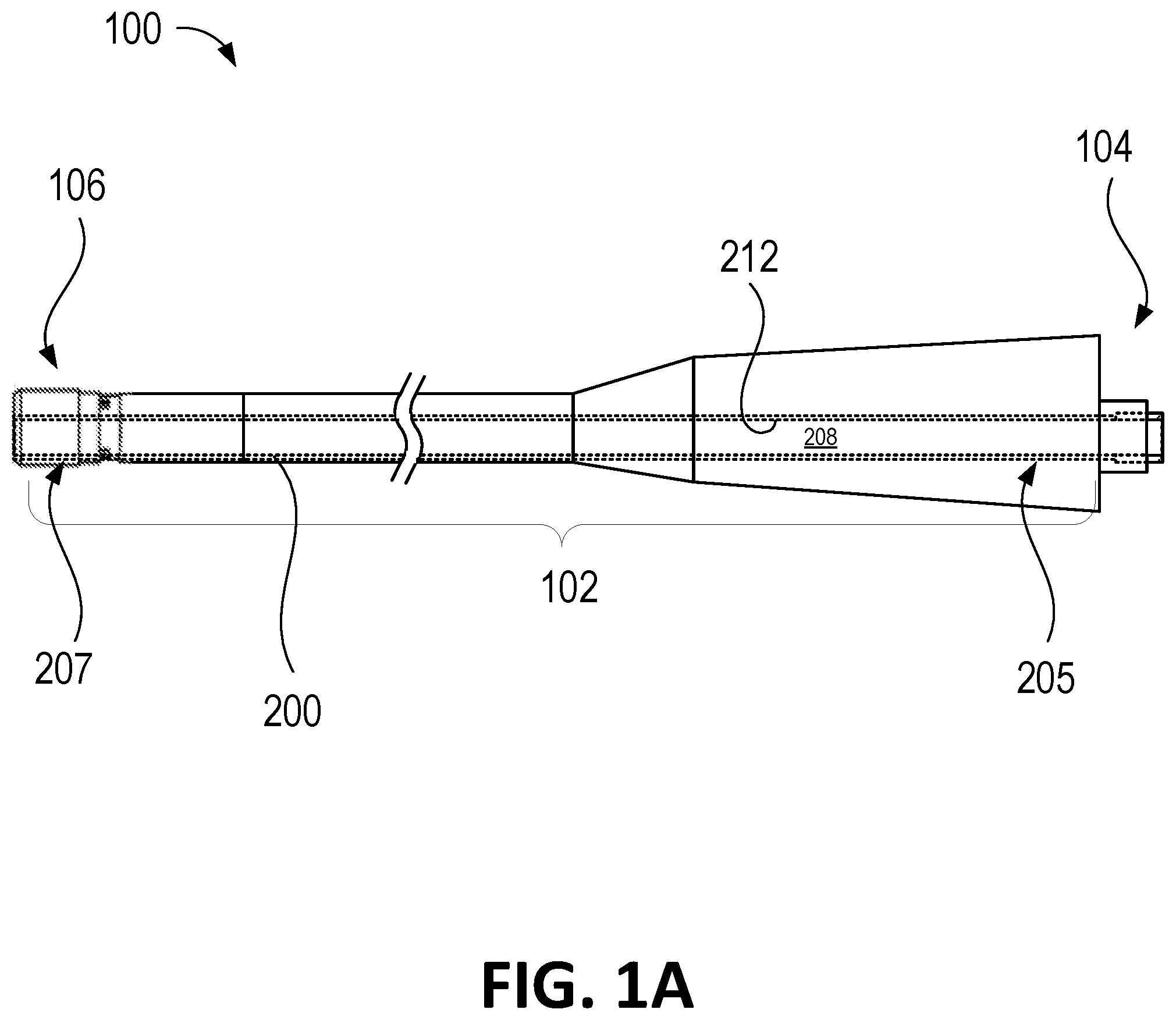
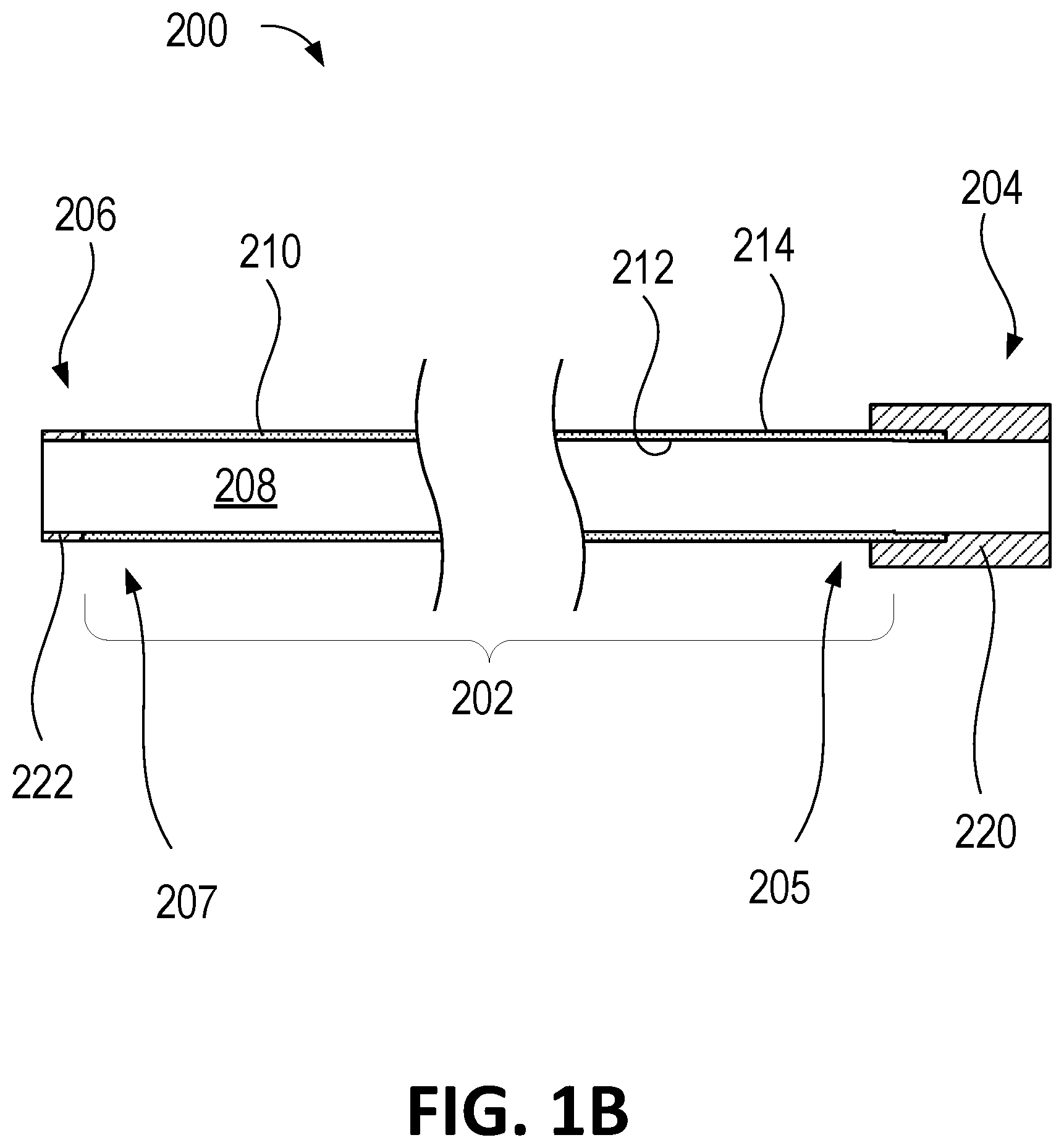
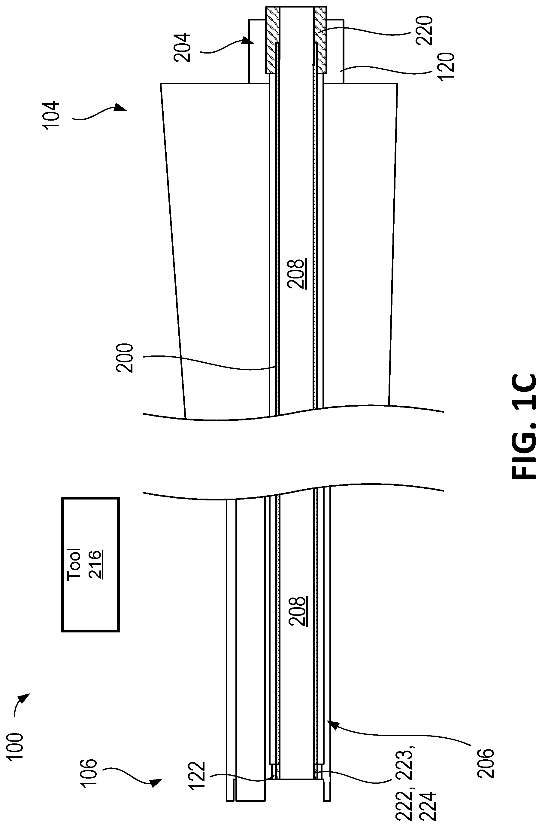
FIGS. 1A-1E illustrate an embodiment of a surgical instrument 100 including a removable working channel 200. FIG. 1A illustrates a side view of the surgical instrument 100. FIG. 1B illustrates a cross-sectional view of the removable working channel 200. FIG. 1C illustrates a cross-sectional view of a proximal portion 104 and a distal portion 106 of the surgical instrument 100, with the removable working channel 200 positioned within the surgical instrument 100. FIG. 1D illustrates a cross-sectional view of the proximal portion 104 and the distal portion 106 of the surgical instrument 100, with the removable working channel 200 removed from the surgical instrument 100. FIG. 1E illustrates a perspective view of a distal portion 106 of the surgical instrument 100. FIGS. 1A-1E are discussed together in portions of the description below due to the overlap of depicted features.
With reference to FIG. 1A, there is shown an example surgical instrument 100 that includes a proximal portion 104 and a distal portion 106 and may include at least one instrument channel 102 extending therethrough. The surgical instrument 100 may further comprise one or more coupling members (not shown here but described in greater detail below) at or near the proximal portion 104 and/or the distal portion 106 of the surgical instrument 100. Though the surgical instrument 100 disclosed in FIG. 1A is described within the context of endoscopic procedures, it will be appreciated that the surgical instrument 100 may include other types of instruments suitable for types of medical procedures. As noted above, examples of the surgical instrument 100 include but are not limited to an endoscope, a bronchoscope, a sinuscope, a nasopharyngoscope, a laryngoscope, a laparoscope, a gastroscope, a colonoscope, a hysteroscope, a cystoscope, a uroscope, a urethroscope, a cardioscope, an arthroscope, etc.
In some embodiments, the instrument channel 102 may have a diameter ranging from about 1.2 mm to about 6 mm. More specifically, the instrument channel 102 may have a diameter about 2.8 mm, about 3.7 mm, about 4.2 mm, and about 6 mm. In some embodiments, the instrument channel 102 may be substantially straight along its longitudinal axis, as illustrated in FIG. 1A. In other embodiments, at least a portion of the instrument channel 102 may be curved. It is to be appreciated that the shape of the instrument channel 102 may depend on how the surgical instrument 100 is actuated or flexed.
As shown in FIG. 1A, the instrument channel 102 of the surgical instrument 100 is configured to receive a removable working channel 200 (drawn with dotted lines to indicate that the removable working channel 200 is inside the surgical instrument 100) such that the removable working channel 200 can be inserted into and/or removed from the instrument channel 102. The removable working channel 200 may be installed within the instrument channel 102 such that an outer surface of the removable working channel 200 interfaces the inner surface of the instrument channel 102. The removable working channel 200, when installed within the instrument channel 102, protects the inner surface of the instrument channel 102 from wear and tear caused by medical tools when passed through the surgical instrument 100.
As shown, the removable working channel 200 includes a proximal region 205, a distal region 207, and an inner surface 212 defining a lumen 208. The lumen 208 of the removable working channel 200 may be a working area usable for the passage of intraoperative instruments, generally referred to herein as medical tools. In other embodiments (not illustrated), one or more additional channels may be incorporated to provide further capabilities, such as, for example, flush/irrigation, aspiration, illumination, laser energy, etc. The lumen 208 of the removable working channel 200 may also be configured to deliver a variety of therapeutic substances along with a tool configured to pass through the removable working channel 200. These substances may be delivered precisely to a target site using the insertion, articulation, and/or other capabilities of the surgical instrument 100 of the present disclosure.
With reference to FIG. 1B, there is shown a cross-sectional view of the removable working channel 200 introduced in FIG. 1A. The removable working channel 200 comprises a shaft 202 and may further comprise one or more locking members 220 and 222 at or near a proximal region 204 and at or near a distal region 206 of the removable working channel 200, respectively. As used herein, the phrase "locking member" may refer to a mechanism for securing the removable working channel to the surgical instrument. The shaft 202 includes the proximal region 205, the distal region 207, and the lumen 208 extending therethrough. The shaft 202 includes a wall 210 comprising the inner surface 212 and an outer surface 214. The inner surface 212 of the shaft 202 defines the lumen 208 extending along the longitudinal length of the shaft 202.
The outer diameter of the shaft 202 may be substantially similar to, equal to, or less than the inner diameter of the instrument channel 102 of the surgical instrument 100. One example of the removable working channel 200 can define a shaft having an outer diameter that is greater than or equal to about 1.2 mm, or less than or equal to about 6 mm. In another example, the removable working channel 200 may have a shaft having an outer diameter of about 3.2 mm. The thickness of the shaft wall 210 may be greater than or equal to about 0.1 mm or less than or equal to about 0.3 mm.
In some embodiments, the shaft 202 of the removable working channel 200 may be made of plastic materials or extruded plastic. For example, the shaft 202 may be made of at least one of polyether block amide (PEBA), Nylon, and polytetrafluoroethylene (PTFE), high-density polyethylene (HDPE), low-density polyethylene (LDPE), linear low density poly ethylene (LLDPE), polyvinyl chloride (PVC), polystyrene, acrylonitrile butadiene styrene (ABS), polypropylene (PP), thermoplastic elastomers (TPE), fluorinated ethylene propylene (FEP), acetal copolymer, polysulfone, polyetheretherketone (PEEK), polyetherimide, polyphenylene oxide (PPO), perfluoroalkoxy (PFA) plastic, polyvinylidene fluoride (PVDF), ethylene tetrafluoroethylene (ETFE), ethylene chlorotrifluoroethylene (ECTFE), tetrafluoroethylene/hexafluoropropylene/vinylidene fluoride (THV) copolymer, or other similar medical grade extrusions. Additionally or alternatively, the shaft 202 may be at least partially made of one or more compressible materials. That way, when the removable working channel 200 is inserted into the surgical instrument 100, the removable working channel 200 may be collapsible or compressible to facilitate the insertion.
In some embodiments, the shaft 202 of the removable working channel 200 may further comprise an inner liner (not shown) attached to the inner surface 212 of the shaft 202. The inner liner may be made of at least one of PTFE, HDPE, LDPE, or LLDPE, or other similar medical grade extrusions. The inner liner may reduce friction and facilitate the passing of medical instruments through the lumen 208 of the removable working channel 200. A lubricant may be added to the surface of the inner liner or the inner surface 212 of the removable working channel 200 to further reduce friction between the surface of the inner liner or the inner surface 212 and the medical instruments.
In one embodiment, the shaft 202 may further comprise a reinforcement member disposed at least partially between the inner surface 212 and the outer surface 214 of the shaft 202. In another embodiment, the reinforcement member may be disposed inside the inner surface 212 of the shaft 202 or outside the outer surface 214 of the shaft 202. Examples of the reinforcement member include one or more coils, one or more braids, or one or more cable tubes. The coils, the braids, and/or the cable tubes may be at least partially made of stainless steel (e.g., stainless steel 304 or stainless steel 316), copper, other metals, Nitinol alloy, graphite, or polymers such as polyparaphenylene terephthalamide (e.g., tradename Kevlar), Ultra-high-molecular-weight polyethylene (UHMWPE) (e.g., tradename Spectra), PEEK, or nylon. It is to be appreciated that other materials may be used depending on the application and the materials just described are not provided in a limiting manner.
As described above with reference to FIG. 1B, the removable working channel 200 may further comprise the one or more locking members 220 at or near the proximal region 204 of the removable working channel 200. The one or more locking members 220 may be configured to releasably couple with the surgical instrument (not shown; see e.g., the surgical instrument 100 in FIG. 1A). As shown in FIG. 1B, the one or more locking members 220 may be at the proximal end of the removable working channel 200. In other examples, the one or more locking members 220 may be placed anywhere in the proximal region 204 of the removable working channel 200.
Similarly, the removable working channel 200 may further comprise the one or more locking members 222 at or near the distal region 206 of the removable working channel 200. The one or more locking members 222 may be configured to releasably couple with the surgical instrument (not shown). As shown in FIG. 1B, the one or more locking members 222 may be at the distal end of the removable working channel 200. In other examples, the one or more locking members 222 may be placed anywhere in the distal region 206 of the removable working channel 200.
With reference to FIG. 1C, there is shown a cross-sectional view of the surgical instrument 100 and the removable working channel 200 inside the surgical instrument 100. The removable working channel 200 is configured to be installed within the surgical instrument 100. The one or more locking members 220 at the proximal end of the removable working channel 200 may be configured to releasably couple with the one or more coupling members 120 of the surgical instrument 100. In another embodiment in which the surgical instrument 100 does not comprise one or more coupling members 120 at or near the proximal portion 104 (not shown), the one or more locking members 220 may be configured to releasably couple to the proximal portion 104 of the surgical instrument 100.
Similarly, the one or more locking members 222 at the distal end of the removable working channel 200 may be configured to releasably couple with the one or more coupling members 122 of the surgical instrument 100. In another embodiment in which the surgical instrument 100 does not comprise one or more coupling members 122 at or near the distal portion 106 (not shown), the one or more locking members 220 may be configured to releasably couple to the distal portion 106 of the surgical instrument 100.
The locking members 220 and 222 of the removable working channel 200 on the proximal region 204 and the distal region 206, respectively, may comprise a removable luer fit component 223, a clamp, a friction fit component (also known as interference fit), a latch, a threaded fit component 224, a slip fit component, a bayonet, a ball spring or pogo latch, a detent, a magnet, a screw lock, a snap fit component, or an O-ring component.
In one example, the locking members 220 and/or 222 may comprise a removable luer fit component configured to fit into a complementary removable luer fit component of the surgical instrument 100. In another example, the locking members 220 and/or 222 may comprise a clamp configured to removably hold at least a portion of the surgical instrument 100 (e.g., proximal portion 104 or distal portion 106). In yet another example, the locking members 220 and/or 222 may comprise a friction fit component configured to slip into the instrument channel 102 of the surgical instrument 100 and lock by friction with the inner surface of the instrument channel 102. In still another example, the locking members 220 and/or 222 may comprise a latch configured to join or fasten to a latch component of the surgical instrument 100 or directly to a portion of the surgical instrument 100. The latch may comprise (1) a ball with a spring or (2) a pogo latch.
In one example, the locking members 220 and/or 222 may comprise a threaded fit component configured to rotatably fit and lock into the instrument channel 102 of the surgical instrument 100 via an interlocking between threads of the threaded fit component and those on the inner surface of the instrument channel 102. In one example, the locking members 220 and/or 222 may comprise a slip fit component configured to fit and lock into the instrument channel 102 of the surgical instrument 100. In another example, the locking members 220 and/or 222 may comprise a bayonet component. The bayonet component may comprise a catch, a detent, or a pin configured to removably couple to a receptor (e.g., a hole, a groove, or an L-shaped groove) on the inner surface of the instrument channel 102 of the surgical instrument 100. Alternatively, the bayonet component of the removable working channel 200 may be a receptor (e.g., a hole, a groove, or an L-shaped groove) configured to receive a catch, a detent, or a pin on the inner surface of the instrument channel 102 of the surgical instrument 100. In yet another example, the locking members 220 and/or 222 may comprise a magnet configured to interact with a magnet at or near the instrument channel 102 of the surgical instrument 100. In still another example, the locking members 220 and/or 222 may comprise a screw lock configured to rotatably lock the removable working channel 200 to the surgical instrument 100 via an interlocking between threads of the screw lock and those on the surgical instrument 100. In another example, the locking members 220 and/or 222 may comprise an O-ring component configured to be placed inside and seal against the instrument channel 102 of the surgical instrument 100.
In some embodiments, the locking members 220 and/or 222 of the removable working channel 200 may comprise one or more locking components configured to engage with a tool 216. The locking members 220 and/or 222 may be releasable from the surgical instrument 100 when, in use, the tool 216 engages and actuates the locking components. In another embodiment, the tool 216 may be configured to selectively actuate and release certain type or types of the locking components. For example, the tool 216 may be a key that is configured to engage and unlock only one type of the locking components. The key may be configured such that the key is not able to engage or unlock other types of the locking components. In yet another embodiment, the tool 216 may be configured to wirelessly communicate with the locking components to actuate them.
As described above with reference to FIG. 1C, the surgical instrument 100 is configured to receive the removable working channel 200. The surgical instrument 100 may further comprise one or more coupling members 122 at or near the distal portion 106 of the surgical instrument 100. The one or more coupling members 122 of the surgical instrument 100 may be configured to releasably couple with the one or more locking members 222 of the removable working channel 200. In another embodiment in which the removable working channel 200 does not comprise one or more locking members at or near the distal region 206 of the removable working channel 200 (not shown), the one or more coupling members 122 may be configured to releasably couple to the distal region 206 of the removable working channel 200. Examples of the coupling members 122 of the surgical instrument 100 are explained below.
As shown in FIG. 1C, the one or more coupling members 122 may be at the distal end of the surgical instrument 100. In other embodiments, the one or more coupling members 122 may be placed anywhere in the distal portion 106 of the surgical instrument 100.
Similarly, the surgical instrument 100 may further comprise one or more coupling members 120 at or near the proximal portion 104 of the surgical instrument 100. The one or more coupling members 120 of the surgical instrument 100 may be configured to releasably couple with the one or more locking members 220 of the removable working channel 200. In another embodiment in which the removable working channel 200 does not comprise one or more locking members at or near the proximal region 204 of the removable working channel 200 (not shown), the one or more coupling members 120 may be configured to releasably couple to the proximal region 204 of the removable working channel 200. For example, the one or more coupling members 120 may comprise a clamp mechanism configured to couple to or pinch at the proximal region 204 of the removable working channel 200.
As shown in FIG. 1C, the one or more coupling members 120 may be at the proximal end of the surgical instrument 100. In other embodiments, the one or more coupling members 120 may be placed anywhere in the proximal portion 104 of the surgical instrument 100.
The coupling members 120 and 122 on the proximal portion 104 and the distal portion 106, respectively, of the surgical instrument 100 may comprise a removable luer fit component, a clamp, a friction fit component (also known as an interference fit component), a latch, a threaded fit component, a slip fit component, a bayonet, a ball spring or pogo latch, a detent, a magnet, a screw lock, a snap fit component, or an O-ring component. In one example, the coupling members 120 and/or 122 of the surgical instrument 100 may comprise a removable luer fit component configured to fit into a complementary removable luer fit component of the removable working channel 200. In another example, the coupling members 120 and/or 122 may comprise a clamp configured to removably hold at least a portion of the removable working channel 200. In yet another example, the coupling members 120 and/or 122 may comprise a friction fit component configured to lock by friction with the outer surface of the removable working channel 200. In still another example, the coupling members 120 and/or 122 may comprise a latch configured to join or fasten to a latch component of the removable working channel 200 or directly to a portion of the removable working channel 200. The latch may comprise (1) a ball with a spring and/or (2) a pogo latch.
In one example, the coupling members 120 and/or 122 may comprise a threaded fit component configured to rotatably fit and lock with the removable working channel 200 via an interlocking between threads of the threaded fit component and those on the outer surface of the removable working channel 200. In one example, the coupling members 120 and/or 122 may comprise a slip fit component configured to fit and lock with the removable working channel 200. In another example, the coupling members 120 and/or 122 may comprise a bayonet component. The bayonet component may comprise a catch, a detent, or a pin configured to removably couple to a receptor (e.g., a hole, a groove, or an L-shaped groove) on the outer surface of the removable working channel 200. Alternatively, the bayonet component of the surgical instrument 100 may be a receptor (e.g., a hole, a groove, or an L-shaped groove) configured to receive a catch, a detent, or a pin on the outer surface of the removable working channel 200. In yet another example, the coupling members 120 and/or 122 may comprise a magnet configured to interact with a magnet placed on the removable working channel 200. In still another example, the coupling members 120 and/or 122 may comprise a screw lock configured to rotatably lock at least a portion of the surgical instrument 100 to at least a portion of the removable working channel 200 via an interlocking between threads of the screw lock and those on the removable working channel 200. In another example, the coupling members 120 and/or 122 may comprise an O-ring component configured to be seal against the removable working channel 200.
In some embodiments, the coupling members 120 and/or 122 of the surgical instrument 100 may comprise one or more locking components configured to engage with a tool 216. The coupling members 120 and/or 122 of the surgical instrument 100 may be configured to be released from the removable working channel 200 when the tool 216 engages and actuates the locking components of the coupling members 120 and/or 122. In another embodiment, the tool 216 may be configured to selectively actuate and release certain type or types of the locking components. For example, the tool 216 may be a key that is configured to engage and unlock only one type of the locking components. The key may be configured such that the key is not able to engage or unlock other types of the locking components. In yet another embodiment, the tool 216 may wirelessly communicate with the locking components to actuate them.
The surgical instrument 100 may comprise a sensor and/or a detector configured to communicate with a processor (e.g., of a surgical robotic system or a computing device in communication with the surgical robotic system) configured to process or verify the information received from the at least one identification member of the removable working channel 200. The user of the surgical instrument 100 (e.g., an operator, a physician, or a robotic surgical system) may set requirements as to which removable working channel 200 may be installed to the surgical instrument 100. After the processor receives information from the removable working channel 200 (e.g., from the sensor or detector), the processor may determine whether the removable working channel 200 satisfies the requirements set by the user. The surgical instrument 100 may be configured to only receive a removable working channel 200 whose information is verified by the processor. In some embodiments, the surgical instrument 100 may be configured to receive only removable working channels 200 whose information satisfies a certain set of requirements set by the user. For example, the surgical instrument 100 may be configured to receive removable working channels 200 produced by verifiable manufacturers only or by a certain set of one or more manufacturers only. In another embodiment, the surgical instrument 100 may be configured to receive only removable working channels 200 that have not been used before. In yet another embodiment, the processor may be configured to transmit a message or otherwise warn a user that one or more requirements of the removable working channel 200 have not been met (e.g., if the source or the manufacturer of the removable working channel 200 is not verifiable).
With reference to FIG. 1D, there is shown a cross-sectional view of the proximal portion 104 and the distal portion 106 of the surgical instrument 100, with the removable working channel 200 removed from the surgical instrument 100. As shown in FIG. 1D, at least a portion of the inner surface 109 of the instrument channel 102 may be covered by a working channel sheath 110. The working channel sheath 110 may be configured to receive the removable working channel 200 as described herein. The removable working channel 200 may be positioned inside the surgical instrument 100 such that the outer surface of the removable working channel 200 interfaces the inner surface 111 of the working channel sheath 110. The working channel sheath 110 may reduce friction between the inner surface 109 of the instrument channel 102 and the removable working channel 200, facilitating the installation and/or removal processes for the removable working channel 200. In other embodiments (not shown), the inner surface 109 of the instrument channel 102 may not be covered with the working channel sheath 110.
The working channel sheath 110 may be made of plastic or extruded plastic. In another embodiment, the working channel sheath 110 may be made of at least one of PEBA, Nylon, PTFE, HDPE, LDPE, LLDPE, PVC, polystyrene, ABS, PP, TPE, FEP, acetal copolymer, polysulfone, PEEK, polyetherimide, PPO, PFA plastic, PVDF, ETFE, ECTFE, and THV copolymer, or other similar medical grade extrusions. In another embodiment, the working channel sheath 110 may further comprise an inner liner attached to the inner surface 111 of the working channel sheath 110. The inner liner may be made of at least one of PTFE, HDPE, LDPE, LLDPE, or other similar medical grade extrusions, or hydrophilic materials. The hydrophilic inner liner coating may be useful for some applications such as tissue/stone removal or easing the passage of medical tools.
The working channel sheath 110 may further comprise one or more coils, one or more braids, or one or more cable tubes. The coils, the braids, and/or the cable tubes may be at least partially inside the working channel sheath 110. In another embodiment, the coils, the braids, and/or the cable tubes may be disposed inside the inner surface 111 of the working channel sheath 110 or outside the outer surface of the working channel sheath 110. The coils, the braids, and/or the cable tubes may be at least partially made of stainless steel (e.g., stainless steel 304 or stainless steel 316), copper, other metals, Nitinol alloy, graphite, or polymers such as polyparaphenylene terephthalamide (e.g., tradename Kevlar), UHMWPE (e.g., tradename Spectra), PEEK, or nylon. It is to be appreciated that other materials may be used depending on the application and the materials just described are not provided in a limiting manner.
Referring to FIG. 1E, the distal portion 106 of the surgical instrument 100 may comprise the distal region 107 of the instrument channel 102, light sources 150 (e.g., light emitting diode (LED), optic fiber, etc.), and a camera 155 (e.g., charge-coupled device (CCD) or complementary metal-oxide-semiconductor (CMOS) camera, terminal end of imaging fiber bundle etc.). In conjunction with the light sources 150, the camera 155 may be used, for example, to capture real-time video to assist with navigation within anatomical structures. Other channels or operating electronics may be provided along the surgical instrument 100 to provide various known capabilities at the distal portion 106, such as wiring to the camera 155, insufflation, suction, electricity, fiber optics, ultrasound transducer, electromagnetic (EM) sensing, and optical coherence tomography (OCT) sensing.
Other Examples of Surgical Instruments and Removable Working Channels
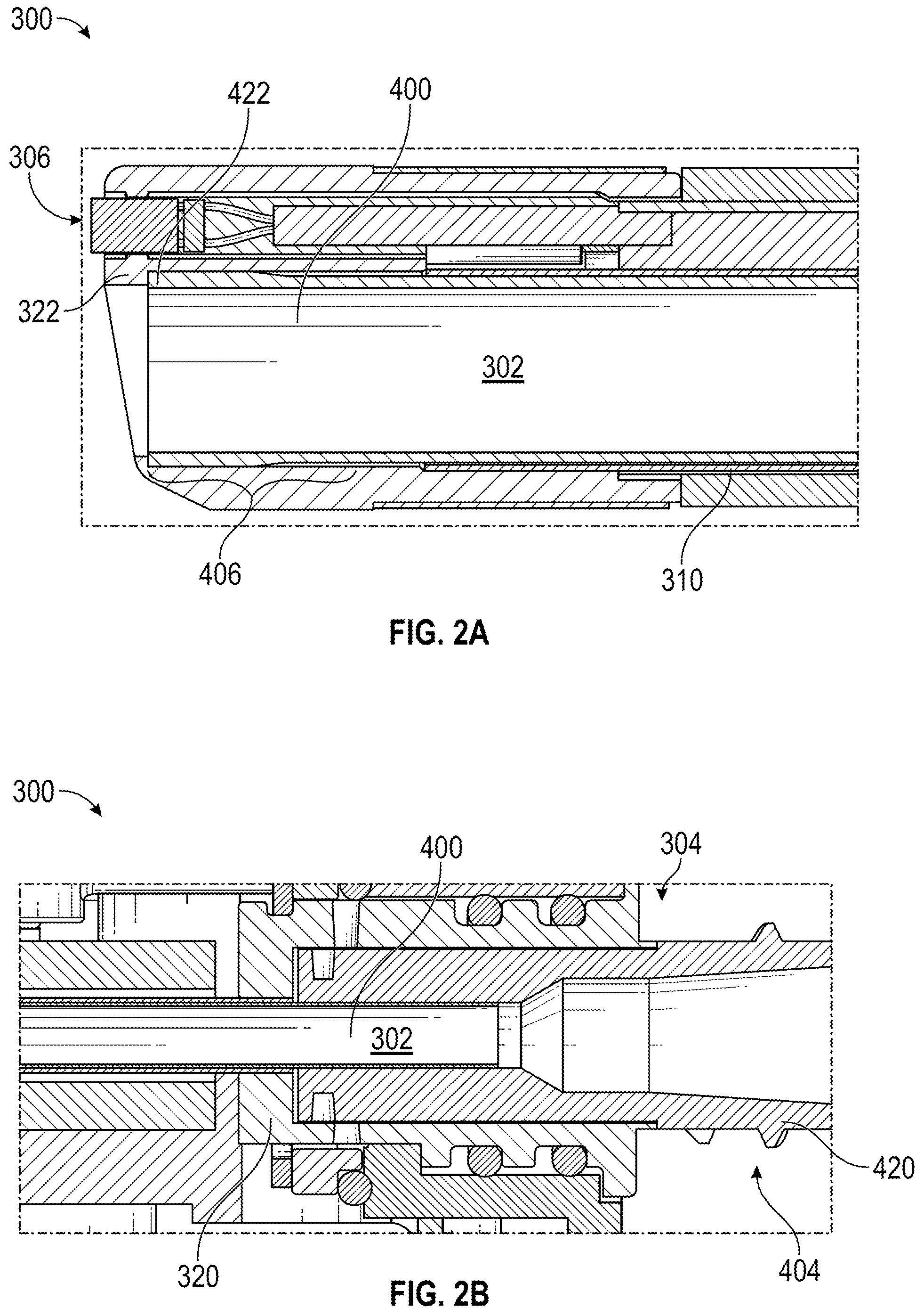
FIGS. 2A-2B illustrate aspects of another embodiment of a surgical instrument 300 including a removable working channel 400 as described herein, wherein the surgical instrument 300 comprises an endoscope and includes (1) a removable luer adapter 320 at the proximal portion 304 of the surgical instrument 300 and (2) a snap fit component 322 at the distal portion 306 of the surgical instrument 300; and the removable working channel 400 comprises (1) a removable luer component 420 at the proximal region 404 of the removable working channel 400 and (2) a snap fit component 422 at the distal region 406 of the removable working channel 400. FIG. 2A illustrates a cross-sectional view of a distal portion 306 of the surgical instrument 300. FIG. 2B illustrates a cross-sectional view of a proximal portion 304 of the surgical instrument 300. FIGS. 2A-2B are discussed together in portions of the description below due to the overlap of depicted features.
In FIGS. 2A-2B, components that can be similar to components described above with reference the embodiment of FIGS. 1A-1E and the description above are identified by similar numbers wherein the reference number used is preceded by the numbers "3" and "4" instead of "1" and "2", respectively. For example, components 302, 304 and 306 can be similar to components 102, 104 and 106, and components 402, 404 and 406 can be similar to components 202, 204 and 206. Reference can be made to the description above for additional descriptions and embodiments of these components which can be used with the embodiment of FIGS. 2A-2B.
Similar to the surgical instrument 100 of FIGS. 1A-1E, the surgical instrument 300 may include at least one instrument channel 302 extending along its longitudinal length. With reference to FIG. 2A, there is shown an embodiment of the surgical instrument 300 comprising an endoscope. The instrument channel 302 of the surgical instrument 300 is configured to receive a removable working channel 400 such that the removable working channel 400 can be inserted into, positioned within, attached to, and/or removed from the instrument channel 302.
Similar to the surgical instrument 100 of FIGS. 1A-1E, at least a portion of the inner surface of the instrument channel 302 of the surgical instrument 300 may be covered with a working channel sheath 310. An outer surface of the working channel sheath 310 interfaces with the inner surface of the instrument channel 302, and an inner surface of the working channel sheath 310 interfaces with the instrument channel 302. The working channel sheath 310 is configured to receive the removable working channel 400 as described herein.
With reference to the embodiment of FIG. 2A, the surgical instrument 300 includes a snap fit component 322 near the distal end of the surgical instrument 300. It is noted that the snap fit component 322 may be placed anywhere in the distal portion 306 of the surgical instrument 300. The snap fit component 322 comprises a step portion configured to abut a distal region 406 of the removable working channel 400. At the distal portion 306 of the surgical instrument 300, the diameter of the instrument channel 302 increases such that the distal portion of the instrument channel 302 can receive the distal region 406 of the removable working channel 400. The removable working channel 400 comprises a snap fit component 422 near the distal end of the removable working channel 400. It is noted that the snap fit component 422 may be placed anywhere in the distal region 406 of the removable working channel 400. The snap fit component 422 is configured to annularly surround the outer surface of the distal region 406 of the removable working channel 400. That way, the outer diameter of the removable working channel 400 at its distal region 406 is greater than that at other regions of the removable working channel 400. As shown in FIG. 2A, the snap fit component 422 may be integrally formed to the distal region 406 of the removable working channel 400. It is to be appreciated that an interference fit component and/or a slip fit component may be used in the distal portion 306 of the surgical instrument 300 instead of or in addition to the snap fit component 322 for simplicity.
The snap fit component 422 of the removable working channel 400 is configured to releasably couple to the snap fit component 322 of the surgical instrument 300. The outer diameter of the distal region 406 of the removable working channel 400 is greater than the diameter of the instrument channel 302 at or near its proximal end. Thus, when the removable working channel 400 is inserted into a proximal end of the instrument channel 302, the distal region 406 of the removable working channel 400 is folded toward the radially inward direction in order for the removable working channel 400 to be able to pass through the instrument channel 302. To facilitate the insertion, the removable working channel 400 may be at least partially made of one or more compressible materials. In some embodiments, when inserting the removable working channel 400 into a proximal end of the instrument channel 302, the user may use a tool (e.g., a mandrel with a handle) to move the removable working channel 400 into the instrument channel 302. When the snap fit component 422 of the removable working channel 400 reaches the distal portion 306 of the surgical instrument 300, the diameter of the instrument channel 302 becomes greater to be substantially similar to the outer diameter of the distal region 406 of the removable working channel 400. As a result, the distal region 406 of the removable working channel 400 radially expands from its folded state to conform to the shape of the instrument channel 302 at the distal portion 306. When the snap fit component 422 of the removable working channel 400 slides along the instrument channel 302 further distally, the distal region 406 of the removable working channel 400 abuts the step portion of the snap fit component 322 of the surgical instrument 300, which prevents a further distal movement of the removable working channel 400.
In some embodiments, the snap fit component 322 of the surgical instrument 300 may comprise an annular recess on an inner surface at or near the distal end of the instrument channel 302, and the snap fit component 422 of the removable working channel 400 may comprise an annular ring on its outer surface. The annular ring of the removable working channel 400 may be configured to snap into and removably couple with the annular recess of the instrument channel 302. In other embodiments, the snap fit component 422 of the removable working channel 400 may comprise a spring clamp on its outer surface. The spring clamp of the removable working channel 400 may be configured to snap into and removably couple with the annular recess of the instrument channel 302. In other embodiments, the snap fit component 322 of the surgical instrument 300 may comprise a wire spring clamp embedded at or near the distal end of the instrument channel 302 (e.g., on the inner surface at or near the distal end of the instrument channel 302). The wire spring clamp may be configured to removably hold the distal region 406 of the removable working channel 400.
The releasable coupling between the two snap fit components 322 and 422 is at least partially achieved by friction between the inner surface of the instrument channel 302 at or near the distal portion 306 and the snap fit component 422 of the removable working channel 400. When the removable working channel 400 is removed from the instrument channel 302 in a proximal direction, the snap fit component 422 of the removable working channel 400 slides in a proximal direction, so the diameter of the instrument channel 302 contacting the snap fit component 422 becomes smaller. As a result, the snap fit component 422 of the removable working channel 400 is forced into the portion of the instrument channel 302 outside the distal region 406 whose diameter is smaller than the outer diameter of the distal region 406 of the removable working channel 400. Accordingly, the snap fit component 422 of the removable working channel 400 is pushed against the inner surface of the instrument channel 302, causing frictions resisting the uncoupling between the two snap fit components 322 and 422. However, the coupling between the two snap fit components 322 and 422 is not permanent and may be released by enough pulling force and/or manipulation of the distal region 406 of the removable working channel 400 (e.g., pulling the distal region 406 toward the radially inward direction) that overcomes the forces of the snap fit. In some embodiments, one or more tools may be used to remove the removable working channel 400 from the instrument channel 302.
With reference to FIG. 2B, the removable working channel 400 comprises a removable luer component 420 at the proximal region 404 of the removable working channel 400. The surgical instrument 300 includes a removable luer adapter 320 at the proximal portion 304 of the surgical instrument 300. The removable luer component 420 of the removable working channel 400 is configured to releasably couple to the removable luer adapter 320 of the surgical instrument 300. The removable luer component 420 of the removable working channel 400 may be configured to slip and fit into the removable luer adapter 320 of the surgical instrument 300. Alternatively, the removable luer component 420 of the removable working channel 400 may be configured to rotatably fit and lock into the removable luer adapter 320 of the surgical instrument 300.
FIGS. 3A-3B illustrate yet another embodiment of a surgical instrument 500 including a removable working channel 600 as described herein, wherein the surgical instrument does not comprise one or more coupling members at or near the distal portion 506 of the surgical instrument 500. FIG. 3A illustrates a cross-sectional view of the surgical instrument 500 as described herein. FIG. 3B illustrates a cross-sectional view of the removable working channel 600 as described herein. FIGS. 3A-3B are discussed together in portions of the description below due to the overlap of depicted features.
In FIGS. 3A-3B, components that can be similar to components described above with reference the embodiment of FIGS. 1A-1E and the description above are identified by similar numbers wherein the reference number used is preceded by the numbers "5" and "6" instead of "1" and "2", respectively. For example, components 502, 504 and 506 can be similar to components 102, 104 and 106, and components 602, 604 and 606 can be similar to components 202, 204 and 206. Reference can be made to the description above for additional descriptions and embodiments of these components which can be used with the embodiment of FIGS. 3A-3B.
With reference to FIG. 3A, the surgical instrument 500 may include at least one instrument channel 502 extending along its longitudinal length. Similar to the surgical instrument 100 of FIGS. 1A-1E, the instrument channel 502 of the surgical instrument 500 is configured to receive the removable working channel 600 such that the removable working channel 600 can be inserted into and/or removed from the instrument channel 502.
Similar to the surgical instrument 100 of FIGS. 1A-1E, at least a portion of the inner surface of the instrument channel 502 of the surgical instrument 500 is covered with a working channel sheath 510. As shown in FIG. 3A, an outer surface of the working channel sheath 510 interfaces with the inner surface of the instrument channel 502, and an inner surface of the working channel sheath 510 interfaces with the instrument channel 502. The working channel sheath 510 is configured to receive the removable working channel 600 as described herein.
As shown in FIG. 3A, the surgical instrument 500 does not comprise one or more coupling members at or near the distal portion 506 of the surgical instrument 500. Thus, the distal portion 506 of the surgical instrument 500 is not configured to lock or couple to the removable working channel 600. Similar to the surgical instrument 100 of FIGS. 1A-1E, the surgical instrument 500 comprises one or more coupling members 520 at the proximal portion 504 of the surgical instrument 500. The coupling members 520 of the surgical instrument 500 may comprise a removable luer fit component, a clamp, a friction fit component (also known as an interference fit component), a latch, a threaded fit component, a slip fit component, a bayonet, a ball spring or pogo latch, a detent, a magnet, a screw lock, a snap fit component, or an O-ring component.
FIG. 3B illustrates a cross-sectional view of the removable working channel 600. Similar to the removable working channel 200 of FIG. 1B, the removable working channel 600 comprises a shaft 602. The shaft 602 includes a proximal end 605, a distal end 607, and a lumen 608 extending therethrough. The shaft 602 includes a wall 610 comprising an inner surface 612 and an outer surface 614. The inner surface 612 of the shaft 602 defines the lumen 608 extending along the longitudinal length of the shaft 602. The outer surface 614 of the shaft 602, when installed, interfaces with the instrument channel 502 of the surgical instrument (not shown).
The removable working channel 600 further comprises one or more locking members 620 at the proximal region 604 of the removable working channel 600. The locking members 620 of the removable working channel 600 are configured to releasably couple to the coupling members 520 of the surgical instrument 500. In an alternate example, the locking members 620 of the removable working channel 600 are configured to releasably couple to the proximal portion 504 of the surgical instrument 500. The locking members 620 of the removable working channel 600 may comprise a removable luer fit component, a clamp, a friction fit component (also known as an interference fit component), a latch, a threaded fit component, a slip fit component, a bayonet, a ball spring or pogo latch, a detent, a magnet, a screw lock, a snap fit component, or an O-ring component. In contrast, the removable working channel 600 does not comprise one or more locking members at or near the distal region 606 of the removable working channel 600 such that the distal region 606 of the removable working channel 600 is not configured to lock or couple to the distal portion 506 of the surgical instrument 500.
Example Identification Members
FIG. 4 illustrates another embodiment of a removable working channel 700 as described herein, wherein the removable working channel 700 further comprises an identification member 730.
In FIG. 4, components that can be similar to components described above with reference the embodiment of FIG. 1B and the description above are identified by similar numbers wherein the reference number used is preceded by the numbers "7" instead of "2", respectively. For example, components 702, 704 and 706 can be similar to components 202, 204 and 206, respectively. Reference can be made to the description above for additional descriptions and embodiments of these components which can be used with the embodiment of FIG. 4.
Similar to the removable working channel 200 of FIG. 1B, the removable working channel 700 comprises a shaft 702 including a proximal end 705, a distal end 707, and a lumen 708 extending therethrough. The shaft 702 includes a wall 710 comprising an inner surface 712 and an outer surface 714. The inner surface 712 of the shaft 702 defines the lumen 708 extending along the longitudinal length of the shaft 702. The outer surface 714 of the shaft 702, when installed, interfaces with the instrument channel of the surgical instrument (not shown). In some embodiments, the removable working channel 700 may further comprise one or more locking members 720 at the proximal region 704 of the removable working channel 700 and/or one or more locking members 722 at the distal region 706 of the removable working channel 700. The locking members 720 and/or 722 of the removable working channel 700 are configured to releasably couple to the surgical instrument (not shown) as described above. The locking members 720 and/or 722 of the removable working channel 700 may comprise a removable luer fit component, a clamp, a friction fit component (also known as an interference fit component), a latch, a threaded fit component, a slip fit component, a bayonet, a ball spring or pogo latch, a detent, a magnet, a screw lock, a snap fit component, or an O-ring component.
With reference to FIG. 4, the removable working channel 700 further comprises one or more identification members 730 configured to store data comprising information regarding the surgical instrument (e.g., one similar to the surgical instrument 100), the removable working channel 700, or both. In some embodiments, the identification member 730 may be attached to the shaft 702 (e.g., on the inner surface 712 or the outer surface 714), or to the locking members 720 and/or 722. Examples of the identification members 730 may include, but not be limited to, a radio-frequency identification (RFID) tag, a near field communication (NFC) tag, a bar code, a Quick Response (QR) code, a Bluetooth low energy (BLE) tag, an ultrasound identification tag, an infrared identification tag, or a video identification tag. The data saved in the identification members 730 may include a source, type, material, dimension, manufacture date, expiration date, and/or identification number of the surgical instrument or the removable working channel 700. In some embodiments, one or more identification members 730 may be installed on the surgical instrument, the removable working channel 700, or both. In other embodiments, the surgical instrument, the removable working channel 700, or both may further comprise at least one sensor or detector configured to read data from the identification members 730.
Example Tool to Couple and/or Uncouple Between Removable Working Channel and Surgical Instrument
In accordance with one or more aspects of the present disclosure, a tool may be configured to couple and/or uncouple between a removable working channel (e.g., removable working channel 200, 400, or 600 as described above) and a surgical instrument (e.g., surgical instrument 100, 300, or 500 as described above). The removable working channel and/or the surgical instrument may be configured to couple and/or uncouple to each other only through the use of a specific type of the tool. This way, only people with the specific type of the tool may install and/or remove the removable working channel onto/from the surgical instrument.
In some embodiments, the tool may be configured to adjust an attachment between the removable working channel and the surgical instrument. The tool may comprise an actuator configured to engage and actuate at least one of (i) one or more locking members (e.g., locking members 220, 420, and/or 620 as described above) at the proximal region of the removable working channel and (ii) one or more coupling members (e.g., coupling members 120, 320, and/or 520 as described above) at the proximal portion of the surgical instrument. In another embodiment, the actuator may be configured to engage and actuate at least one of (i) one or more locking members (e.g., locking members 222 and/or 422 as described above) at the distal region of the removable working channel and (ii) one or more coupling members (e.g., coupling members 122 and/or 322 as described above) at the distal portion of the surgical instrument.
The engagement and actuation of the at least one of (i) one or more locking members and (ii) one or more coupling members by the actuator facilitates locking and/or unlocking an attachment between the removable working channel and the surgical instrument. In another embodiment, the tool may be configured to wirelessly communicate with the one or more locking members of the removable working channel to engage or actuate the one or more locking members. In yet another embodiment, the tool may be configured to wirelessly communicate with the one or more coupling members of the surgical instrument to engage or actuate the one or more coupling members. Examples of the tool include, and are not limited to, a key, a driver, a pipe, a needle, and a transmitter.
In some embodiments, the actuator of the tool may be configured to be able to engage only with a certain type or types of the locking members and/or the coupling members. Such an exclusive engagement may be enabled by (1) physical features of the actuator, the locking members, and/or the coupling members or (2) electronic or wireless communications between the tool and the locking members or the coupling members. For example, in one embodiment, the actuator of the tool may have a physical shape that can engage with only a certain type or types of the locking members and/or the coupling members. In another embodiment, the tool may be configured to wirelessly communicate with the locking members and/or the coupling members to allow engagement with only a certain type or types of the locking members and/or the coupling members.
Example Method for Sanitizing or Replacing Removable Working Channels of Surgical Instrument
With the removable working channel and the surgical instrument described herein, a user may sanitize or replace the surgical instrument by removing a removable working channel installed in an instrument channel of the surgical instrument, checking the integrity of the removable working channel, and then either (1) cleaning and reinstalling the removable working channel or (2) replacing the removable working channel with a new removable working channel in the surgical instrument, depending on the integrity of the first removable working channel.
FIG. 5 depicts a flowchart illustrating an embodiment of a process 800 of sanitizing or replacing one or more removable working channels (e.g., removable working channels 200, 400, 600, and 700 as described above) of a surgical instrument described herein (e.g., surgical instruments 100, 300, and 500 as described above), wherein the process 800 may be conducted by a user. The user may include, but not be limited to, hospitals, physicians, healthcare practitioners, third-party cleaning service companies, medical device companies, and/or autonomous systems. The process 800 may also be implemented, entirely or in part, by an automated system (e.g., robotic system). It will be appreciated that although components described in the process 800 may be identified by the reference numbers used for the embodiment of FIGS. 1A-1E, these components are not limited to the embodiment of FIGS. 1A-1E.
At block 805, the user (e.g., a human operator or an autonomous system) may remove a first removable working channel from a surgical instrument. For example, in implementations in which the removable working channel 200 is installed in the instrument channel 102 of the surgical instrument 100, removing the first removable working channel may comprise removing the removable working channel 200 out of the proximal end of the instrument channel 102. In implementations in which the surgical instrument 100 comprises one or more coupling members 120 and/or 122, and the first removable working channel 200 comprises one or more locking members 220 and/or 222, which are configured to releasably couple to the one or more coupling members 120 and/or 122 of the surgical instrument 100, respectively, block 805 may involve (1) engaging a tool to at least one of (i) the one or more coupling members 120 and/or 122 of the surgical instrument 100 and (ii) the one or more locking members 220 an
D00000
D00001
D00002
D00003
D00004
D00005
D00006
D00007
D00008
D00009
D00010
XML
uspto.report is an independent third-party trademark research tool that is not affiliated, endorsed, or sponsored by the United States Patent and Trademark Office (USPTO) or any other governmental organization. The information provided by uspto.report is based on publicly available data at the time of writing and is intended for informational purposes only.
While we strive to provide accurate and up-to-date information, we do not guarantee the accuracy, completeness, reliability, or suitability of the information displayed on this site. The use of this site is at your own risk. Any reliance you place on such information is therefore strictly at your own risk.
All official trademark data, including owner information, should be verified by visiting the official USPTO website at www.uspto.gov. This site is not intended to replace professional legal advice and should not be used as a substitute for consulting with a legal professional who is knowledgeable about trademark law.