Methods of network peer identification and self-organization using unique tonal signatures and wells that use the methods
Walker , et al.
U.S. patent number 10,711,600 [Application Number 16/267,950] was granted by the patent office on 2020-07-14 for methods of network peer identification and self-organization using unique tonal signatures and wells that use the methods. This patent grant is currently assigned to ExxonMobil Upstream Research Company. The grantee listed for this patent is Scott William Clawson, Katie M. Walker. Invention is credited to Scott William Clawson, Katie M. Walker.
| United States Patent | 10,711,600 |
| Walker , et al. | July 14, 2020 |
Methods of network peer identification and self-organization using unique tonal signatures and wells that use the methods
Abstract
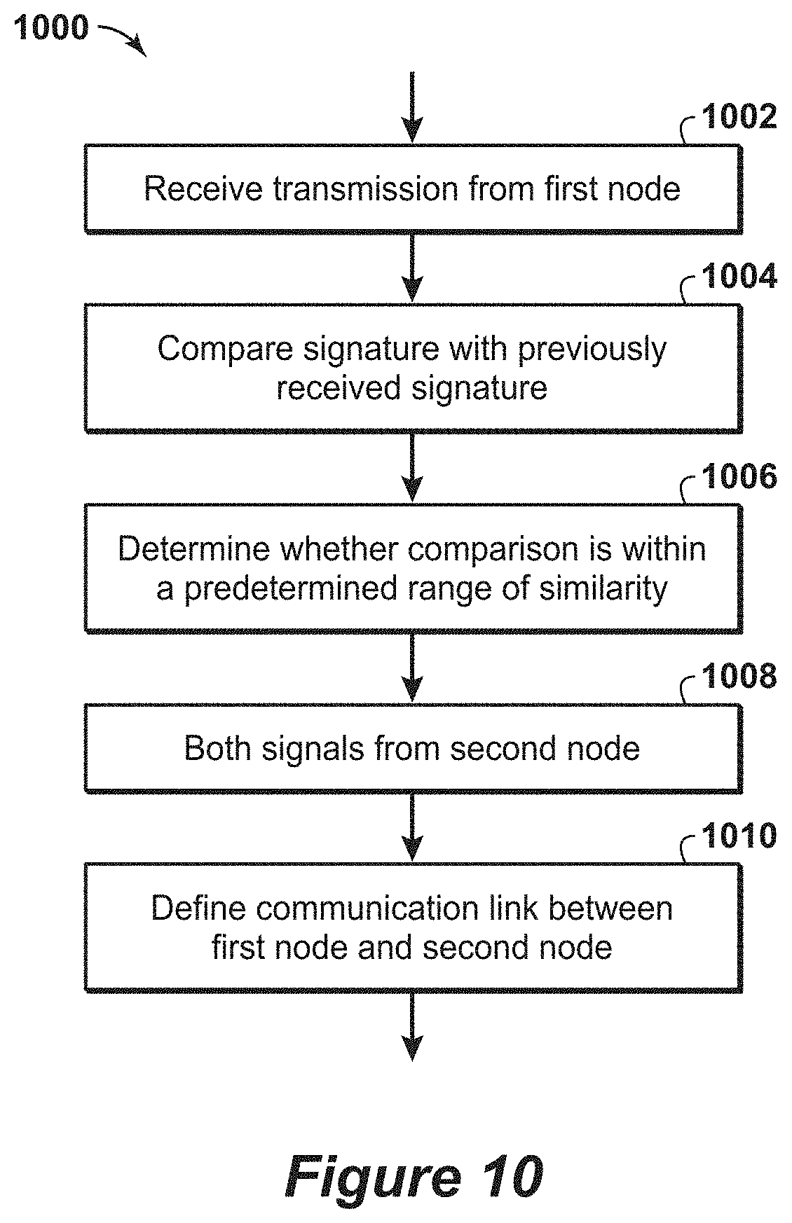
A method of communication using a wireless network is disclosed. A wireless transmission of a signal is received at a first node. The signal has a frequency signature. The frequency signature of the received signal is compared with a frequency signature of a previously received signal from a second node. If it is determined that the frequency signature of the received signal and the frequency signature of the previously received signal are within a predetermined range of similarity, the received signal and the previously received signal are accepted as having been transmitted by the second node.
| Inventors: | Walker; Katie M. (Spring, TX), Clawson; Scott William (Califon, NJ) | ||||||||||
|---|---|---|---|---|---|---|---|---|---|---|---|
| Applicant: |
|
||||||||||
| Assignee: | ExxonMobil Upstream Research
Company (Spring, TX) |
||||||||||
| Family ID: | 65494564 | ||||||||||
| Appl. No.: | 16/267,950 | ||||||||||
| Filed: | February 5, 2019 |
Prior Publication Data
| Document Identifier | Publication Date | |
|---|---|---|
| US 20190242249 A1 | Aug 8, 2019 | |
Related U.S. Patent Documents
| Application Number | Filing Date | Patent Number | Issue Date | ||
|---|---|---|---|---|---|
| 62799881 | Feb 1, 2019 | ||||
| 62628105 | Feb 8, 2018 | ||||
| Current U.S. Class: | 1/1 |
| Current CPC Class: | E21B 47/14 (20130101); H04W 24/02 (20130101); H04W 76/10 (20180201); H04B 11/00 (20130101) |
| Current International Class: | E21B 47/14 (20060101); H04W 24/02 (20090101); H04B 11/00 (20060101); H04W 76/10 (20180101) |
References Cited [Referenced By]
U.S. Patent Documents
| 3103643 | September 1963 | Kalbfell |
| 3205477 | September 1965 | Kalbfell |
| 3512407 | May 1970 | Zill |
| 3637010 | January 1972 | Malay et al. |
| 3741301 | June 1973 | Malay et al. |
| 3781783 | December 1973 | Tucker |
| 3790930 | February 1974 | Lamel et al. |
| 3900827 | August 1975 | Lamel et al. |
| 3906434 | September 1975 | Lamel et al. |
| 4001773 | January 1977 | Lamel et al. |
| 4283780 | August 1981 | Nardi |
| 4298970 | November 1981 | Shawhan et al. |
| 4302826 | November 1981 | Kent et al. |
| 4314365 | February 1982 | Petersen et al. |
| 4884071 | November 1989 | Howard |
| 4962489 | October 1990 | Medlin et al. |
| 5128901 | July 1992 | Drumheller |
| 5136613 | August 1992 | Dumestre, III |
| 5166908 | November 1992 | Montgomery |
| 5182946 | February 1993 | Boughner et al. |
| 5234055 | August 1993 | Cornette |
| 5283768 | February 1994 | Rorden |
| 5373481 | December 1994 | Orban et al. |
| 5468025 | November 1995 | Adinolfe et al. |
| 5480201 | January 1996 | Mercer |
| 5495230 | February 1996 | Lian |
| 5562240 | October 1996 | Campbell |
| 5592438 | January 1997 | Rorden et al. |
| 5667650 | September 1997 | Face et al. |
| 5850369 | December 1998 | Rorden et al. |
| 5857146 | January 1999 | Kido |
| 5924499 | July 1999 | Birchak et al. |
| 5960883 | October 1999 | Tubel et al. |
| 5995449 | November 1999 | Green et al. |
| 6049508 | April 2000 | Deflandre |
| 6125080 | September 2000 | Sonnenschein et al. |
| 6128250 | October 2000 | Reid et al. |
| 6177882 | January 2001 | Ringgenberg et al. |
| 6236850 | May 2001 | Desai |
| 6239690 | May 2001 | Burbidge et al. |
| 6300743 | October 2001 | Patino et al. |
| 6320820 | November 2001 | Gardner et al. |
| 6324904 | December 2001 | Ishikawa et al. |
| 6360769 | March 2002 | Brisco |
| 6394184 | May 2002 | Tolman et al. |
| 6400646 | June 2002 | Shah et al. |
| 6429784 | August 2002 | Beique et al. |
| 6462672 | October 2002 | Besson |
| 6543538 | April 2003 | Tolman et al. |
| 6670880 | December 2003 | Hall et al. |
| 6679332 | January 2004 | Vinegar et al. |
| 6695277 | February 2004 | Gallis |
| 6702019 | March 2004 | Dusterhoft et al. |
| 6717501 | April 2004 | Hall et al. |
| 6727827 | April 2004 | Edwards et al. |
| 6772837 | August 2004 | Dusterhoft et al. |
| 6816082 | November 2004 | Laborde |
| 6868037 | March 2005 | Dasgupta et al. |
| 6880634 | April 2005 | Gardner et al. |
| 6883608 | April 2005 | Parlar et al. |
| 6899178 | May 2005 | Tubel |
| 6909667 | June 2005 | Shah et al. |
| 6912177 | June 2005 | Smith |
| 6920085 | July 2005 | Finke et al. |
| 6930616 | August 2005 | Tang et al. |
| 6940392 | September 2005 | Chan et al. |
| 6940420 | September 2005 | Jenkins |
| 6953094 | October 2005 | Ross et al. |
| 6956791 | October 2005 | Dopf et al. |
| 6980929 | December 2005 | Aronstam et al. |
| 6987463 | January 2006 | Beique et al. |
| 7006918 | February 2006 | Economides et al. |
| 7011157 | March 2006 | Costley et al. |
| 7036601 | May 2006 | Berg et al. |
| 7051812 | May 2006 | McKee et al. |
| 7064676 | June 2006 | Hall et al. |
| 7082993 | August 2006 | Ayoub et al. |
| 7090020 | August 2006 | Hill et al. |
| 7140434 | November 2006 | Chouzenoux et al. |
| 7219762 | May 2007 | James et al. |
| 7224288 | May 2007 | Hall et al. |
| 7228902 | June 2007 | Oppelt |
| 7249636 | July 2007 | Ohmer |
| 7252152 | August 2007 | LoGiudice et al. |
| 7257050 | August 2007 | Stewart et al. |
| 7261154 | August 2007 | Hall et al. |
| 7261162 | August 2007 | Deans et al. |
| 7275597 | October 2007 | Hall et al. |
| 7277026 | October 2007 | Hall et al. |
| RE40032 | January 2008 | van Bokhorst et al. |
| 7317990 | January 2008 | Sinha et al. |
| 7321788 | January 2008 | Addy et al. |
| 7322416 | January 2008 | Burris, II et al. |
| 7325605 | February 2008 | Fripp et al. |
| 7339494 | March 2008 | Shah et al. |
| 7348893 | March 2008 | Huang et al. |
| 7385523 | June 2008 | Thomeer et al. |
| 7387165 | June 2008 | Lopez de Cardenas et al. |
| 7411517 | August 2008 | Flanagan |
| 7477160 | January 2009 | Lemenager et al. |
| 7516792 | April 2009 | Lonnes et al. |
| 7551057 | June 2009 | King et al. |
| 7590029 | September 2009 | Tingley |
| 7595737 | September 2009 | Fink et al. |
| 7602668 | October 2009 | Liang et al. |
| 7649473 | January 2010 | Johnson et al. |
| 7750808 | July 2010 | Masino et al. |
| 7775279 | August 2010 | Marya et al. |
| 7787327 | August 2010 | Tang et al. |
| 7819188 | October 2010 | Auzerais et al. |
| 7828079 | November 2010 | Oothoudt |
| 7831283 | November 2010 | Ogushi et al. |
| 7913773 | March 2011 | Li et al. |
| 7952487 | May 2011 | Montebovi |
| 7994932 | August 2011 | Huang et al. |
| 8004421 | August 2011 | Clark |
| 8044821 | October 2011 | Mehta |
| 8049506 | November 2011 | Lazarev |
| 8115651 | February 2012 | Camwell et al. |
| 8117907 | February 2012 | Han et al. |
| 8157008 | April 2012 | Lilley |
| 8162050 | April 2012 | Roddy et al. |
| 8220542 | July 2012 | Whitsitt et al. |
| 8237585 | August 2012 | Zimmerman |
| 8242928 | August 2012 | Prammer |
| 8276674 | October 2012 | Lopez de Cardenas et al. |
| 8284075 | October 2012 | Fincher et al. |
| 8284947 | October 2012 | Giesbrecht et al. |
| 8316936 | November 2012 | Roddy et al. |
| 8330617 | December 2012 | Chen et al. |
| 8347982 | January 2013 | Hannegan et al. |
| 8358220 | January 2013 | Savage |
| 8376065 | February 2013 | Teodorescu et al. |
| 8381822 | February 2013 | Hales et al. |
| 8388899 | March 2013 | Mitani et al. |
| 8411530 | April 2013 | Slocum et al. |
| 8434354 | May 2013 | Crow et al. |
| 8494070 | July 2013 | Luo et al. |
| 8496055 | July 2013 | Mootoo et al. |
| 8539890 | September 2013 | Tripp et al. |
| 8544564 | October 2013 | Moore et al. |
| 8552597 | October 2013 | Song et al. |
| 8556302 | October 2013 | Dole |
| 8559272 | October 2013 | Wang |
| 8596359 | December 2013 | Grigsby et al. |
| 8605548 | December 2013 | Froelich |
| 8607864 | December 2013 | Mcleod et al. |
| 8664958 | March 2014 | Simon |
| 8672875 | March 2014 | Vanderveen et al. |
| 8675779 | March 2014 | Zeppetelle et al. |
| 8683859 | April 2014 | Godager |
| 8689621 | April 2014 | Godager |
| 8701480 | April 2014 | Eriksen |
| 8750789 | June 2014 | Baldemair et al. |
| 8787840 | July 2014 | Srinivasan et al. |
| 8805632 | August 2014 | Coman et al. |
| 8826980 | September 2014 | Neer |
| 8833469 | September 2014 | Purkis |
| 8893784 | November 2014 | Abad |
| 8910716 | December 2014 | Newton et al. |
| 8994550 | March 2015 | Millot et al. |
| 8995837 | March 2015 | Mizuguchi et al. |
| 9062508 | June 2015 | Huval et al. |
| 9062531 | June 2015 | Jones |
| 9075155 | July 2015 | Luscombe et al. |
| 9078055 | July 2015 | Nguyen et al. |
| 9091153 | July 2015 | Yang et al. |
| 9133705 | September 2015 | Angeles Boza |
| 9140097 | September 2015 | Themig et al. |
| 9144894 | September 2015 | Barnett et al. |
| 9206645 | December 2015 | Hallundbaek |
| 9279301 | March 2016 | Lovorn et al. |
| 9284819 | March 2016 | Tolman et al. |
| 9284834 | March 2016 | Alteirac et al. |
| 9310510 | April 2016 | Godager |
| 9333350 | May 2016 | Rise et al. |
| 9334696 | May 2016 | Hay |
| 9359841 | June 2016 | Hall |
| 9363605 | June 2016 | Goodman et al. |
| 9376908 | June 2016 | Ludwig et al. |
| 9441470 | September 2016 | Guerrero |
| 9515748 | December 2016 | Jeong et al. |
| 9557434 | January 2017 | Keller et al. |
| 9617829 | April 2017 | Dale et al. |
| 9617850 | April 2017 | Fripp et al. |
| 9631485 | April 2017 | Keller et al. |
| 9657564 | May 2017 | Stolpman |
| 9664037 | May 2017 | Logan et al. |
| 9670773 | June 2017 | Croux |
| 9683434 | June 2017 | Machocki |
| 9686021 | June 2017 | Merino |
| 9715031 | July 2017 | Contant et al. |
| 9721448 | August 2017 | Wu et al. |
| 9759062 | September 2017 | Deffenbaugh et al. |
| 9816373 | November 2017 | Howell et al. |
| 9822634 | November 2017 | Gao |
| 9863222 | January 2018 | Morrow et al. |
| 9879525 | January 2018 | Morrow et al. |
| 9945204 | April 2018 | Ross et al. |
| 9963955 | May 2018 | Tolman et al. |
| 10100635 | October 2018 | Keller et al. |
| 10103846 | October 2018 | van Zelm et al. |
| 10132149 | November 2018 | Morrow et al. |
| 10145228 | December 2018 | Yarus et al. |
| 10167716 | January 2019 | Clawson et al. |
| 10167717 | January 2019 | Deffenbaugh et al. |
| 10190410 | January 2019 | Clawson et al. |
| 10196862 | February 2019 | Li-Leger et al. |
| 2002/0180613 | December 2002 | Shi et al. |
| 2003/0056953 | March 2003 | Tumlin et al. |
| 2003/0117896 | June 2003 | Sakuma et al. |
| 2004/0020063 | February 2004 | Lewis et al. |
| 2004/0200613 | October 2004 | Fripp et al. |
| 2004/0239521 | December 2004 | Zierolf |
| 2005/0269083 | December 2005 | Burris, II et al. |
| 2005/0284659 | December 2005 | Hall et al. |
| 2006/0033638 | February 2006 | Hall et al. |
| 2006/0041795 | February 2006 | Gabelmann et al. |
| 2006/0090893 | May 2006 | Sheffield |
| 2007/0139217 | June 2007 | Beique et al. |
| 2007/0146351 | June 2007 | Katsurahira et al. |
| 2007/0156359 | July 2007 | Varsamis et al. |
| 2007/0219758 | September 2007 | Bloomfield |
| 2007/0254604 | November 2007 | Kim |
| 2007/0272411 | November 2007 | Lopez de Cardenas et al. |
| 2008/0030365 | February 2008 | Fripp et al. |
| 2008/0060505 | March 2008 | Chang |
| 2008/0076536 | March 2008 | Shayesteh |
| 2008/0110644 | May 2008 | Howell et al. |
| 2008/0185144 | August 2008 | Lovell |
| 2008/0304360 | December 2008 | Mozer |
| 2009/0003133 | January 2009 | Dalton et al. |
| 2009/0030614 | January 2009 | Carnegie et al. |
| 2009/0034368 | February 2009 | Johnson |
| 2009/0045974 | February 2009 | Patel |
| 2009/0080291 | March 2009 | Tubel et al. |
| 2009/0166031 | July 2009 | Hernandez |
| 2010/0013663 | January 2010 | Cavender et al. |
| 2010/0080086 | April 2010 | Wright |
| 2010/0089141 | April 2010 | Rioufol et al. |
| 2010/0112631 | May 2010 | Hur et al. |
| 2010/0133004 | June 2010 | Burleson et al. |
| 2010/0182161 | July 2010 | Robbins et al. |
| 2010/0212891 | August 2010 | Stewart et al. |
| 2011/0061862 | March 2011 | Loretz et al. |
| 2011/0066378 | March 2011 | Lerche et al. |
| 2011/0168403 | July 2011 | Patel |
| 2011/0188345 | August 2011 | Wang |
| 2011/0297376 | December 2011 | Holderman et al. |
| 2011/0297673 | December 2011 | Zbat et al. |
| 2011/0301439 | December 2011 | Albert et al. |
| 2011/0315377 | December 2011 | Rioufol |
| 2012/0043079 | February 2012 | Wassouf et al. |
| 2012/0126992 | May 2012 | Rodney et al. |
| 2012/0152562 | June 2012 | Newton et al. |
| 2012/0179377 | July 2012 | Lie |
| 2013/0000981 | January 2013 | Grimmer et al. |
| 2013/0003503 | January 2013 | L'Her et al. |
| 2013/0106615 | May 2013 | Prammer |
| 2013/0138254 | May 2013 | Seals et al. |
| 2013/0192823 | August 2013 | Barrilleaux et al. |
| 2013/0278432 | October 2013 | Shashoua et al. |
| 2013/0319102 | December 2013 | Ringgenberg et al. |
| 2014/0060840 | March 2014 | Hartshorne et al. |
| 2014/0062715 | March 2014 | Clark |
| 2014/0079242 | March 2014 | Nguyen |
| 2014/0102708 | April 2014 | Purkis et al. |
| 2014/0133276 | May 2014 | Volker et al. |
| 2014/0152659 | June 2014 | Davidson et al. |
| 2014/0153368 | June 2014 | Bar-Cohen et al. |
| 2014/0166266 | June 2014 | Read |
| 2014/0170025 | June 2014 | Weiner et al. |
| 2014/0266769 | September 2014 | van Zelm |
| 2014/0327552 | November 2014 | Filas et al. |
| 2014/0352955 | December 2014 | Tubel et al. |
| 2015/0003202 | January 2015 | Palmer et al. |
| 2015/0009040 | January 2015 | Bowles et al. |
| 2015/0027687 | January 2015 | Tubel |
| 2015/0041124 | February 2015 | Rodriguez |
| 2015/0041137 | February 2015 | Rodriguez |
| 2015/0152727 | June 2015 | Fripp et al. |
| 2015/0159481 | June 2015 | Mebarkia et al. |
| 2015/0167425 | June 2015 | Hammer et al. |
| 2015/0176370 | June 2015 | Greening et al. |
| 2015/0292319 | October 2015 | Disko et al. |
| 2015/0292320 | October 2015 | Lynk et al. |
| 2015/0300159 | October 2015 | Stiles et al. |
| 2015/0330200 | November 2015 | Richard et al. |
| 2015/0337642 | November 2015 | Spacek |
| 2015/0354351 | December 2015 | Morrow et al. |
| 2015/0377016 | December 2015 | Ahmad |
| 2016/0010446 | January 2016 | Logan et al. |
| 2016/0047230 | February 2016 | Livescu et al. |
| 2016/0047233 | February 2016 | Butner et al. |
| 2016/0076363 | March 2016 | Morrow et al. |
| 2016/0109606 | April 2016 | Market et al. |
| 2016/0215612 | July 2016 | Morrow |
| 2017/0138185 | May 2017 | Saed et al. |
| 2017/0145811 | May 2017 | Robison et al. |
| 2017/0152741 | June 2017 | Park et al. |
| 2017/0167249 | June 2017 | Lee et al. |
| 2017/0204719 | July 2017 | Babakhani |
| 2017/0254183 | September 2017 | Vasques et al. |
| 2017/0293044 | October 2017 | Gilstrap et al. |
| 2017/0314386 | November 2017 | Orban et al. |
| 2018/0010449 | January 2018 | Roberson et al. |
| 2018/0058191 | March 2018 | Romer et al. |
| 2018/0058198 | March 2018 | Ertas et al. |
| 2018/0058202 | March 2018 | Disko et al. |
| 2018/0058203 | March 2018 | Clawson et al. |
| 2018/0058204 | March 2018 | Clawson et al. |
| 2018/0058205 | March 2018 | Clawson et al. |
| 2018/0058206 | March 2018 | Zhang et al. |
| 2018/0058207 | March 2018 | Song et al. |
| 2018/0058208 | March 2018 | Song et al. |
| 2018/0058209 | March 2018 | Song et al. |
| 2018/0066490 | March 2018 | Kjos |
| 2018/0066510 | March 2018 | Walker et al. |
| 2019/0112913 | April 2019 | Song et al. |
| 2019/0112915 | April 2019 | Disko et al. |
| 2019/0112916 | April 2019 | Song et al. |
| 2019/0112917 | April 2019 | Disko et al. |
| 2019/0112918 | April 2019 | Yi et al. |
| 2019/0112919 | April 2019 | Song et al. |
| 2019/0116085 | April 2019 | Zhang et al. |
| 102733799 | Jun 2014 | CN | |||
| 0636763 | Feb 1995 | EP | |||
| 1409839 | Apr 2005 | EP | |||
| 2677698 | Dec 2013 | EP | |||
| 2763335 | Aug 2014 | EP | |||
| WO2002/027139 | Apr 2002 | WO | |||
| WO2010/074766 | Jul 2010 | WO | |||
| WO2013/079928 | Jun 2013 | WO | |||
| WO20141018010 | Jan 2014 | WO | |||
| WO2014/049360 | Apr 2014 | WO | |||
| WO2014/100271 | Jun 2014 | WO | |||
| WO2014/134741 | Sep 2014 | WO | |||
| WO2015/117060 | Aug 2015 | WO | |||
Other References
|
US. Appl. No. 15/666,334, filed Aug. 1, 2017, Walker, Katie M. et al. cited by applicant . U.S. Appl. No. 16/175,441, filed Oct. 30, 2018, Song, Limin et al. cited by applicant . U.S. Appl. No. 16/175,467, filed Oct. 30, 2018, Kinn, Timothy F. et al. cited by applicant . U.S. Appl. No. 16/175,488, filed Oct. 30, 2018, Yi, Xiaohua et al. cited by applicant . U.S. Appl. No. 16/220,327, filed Dec. 14, 2018, Disko, Mark M. et al. cited by applicant . U.S. Appl. No. 16/220,332, filed Dec. 14, 2018, Yi, Xiaohua et al. cited by applicant . U.S. Appl. No. 16/269,083, filed Feb. 6, 2019, Zhang, Yibing. cited by applicant . U.S. Appl. No. 16/267,950, filed Feb. 5, 2019, Walker, Katie M. et al. cited by applicant . U.S. Appl. No. 62/782,153, filed Dec. 19, 2019, Yi, Xiaohua et al. cited by applicant . U.S. Appl. No. 62/782,160, filed Dec. 19, 2018, Hall, Timothy J. et al. cited by applicant . Arroyo, Javier et al. (2009) "Forecasting Histogram Time Series with K-Nearest Neighbours Methods," International Journal of Forecasting, vol. 25, pp. 192-207. cited by applicant . Arroyo, Javier et al. (2011) "Smoothing Methods for Histogram-Valued Time Seriers: An Application to Value-at-Risk," Univ. of California, Dept. of Economics, www.wileyonlinelibrary.com, Mar. 8, 2011, 28 pages. cited by applicant . Arroyo, Javier et al. (2011) "Forecasting with Interval and Histogram Data Some Financial Applications," Univ. of California, Dept. of Economics, 46 pages. cited by applicant . Emerson Process Management (2011), "Roxar downhole Wireless PT sensor system," www.roxar.com, or downhole@roxar.com, 2 pgs. cited by applicant . Gonzalez-Rivera, Gloria et al. (2012) "Time Series Modeling of Histogram-Valued Data: The Daily Histogram Time Series of S&P500 Intradaily Returns," International Journal of Forecasting, vol. 28, 36 pgs. cited by applicant . Gutierrez-Estevez, M. A. et al. (2013) "Acoustic Boardband Communications Over Deep Drill Strings using Adaptive OFDM", IEEE Wireless Comm. & Networking Conf., pp. 4089-4094. cited by applicant . Qu, X. et al. (2011) "Reconstruction fo Self-Sparse 20 NMR Spectra From undersampled Data in the Indirect Dimension", pp. 8888-8909. cited by applicant . U.S. Department of Defense (1999) "Interoperability and Performance Standards for Medium and High Frequency Radio Systems," MIL-STD-188-141B, Mar. 1, 1999, 584 pages. cited by applicant. |
Primary Examiner: Khan; Omer S
Attorney, Agent or Firm: ExxonMobil Upstream Research Company--Law Department
Parent Case Text
CROSS REFERENCE TO RELATED APPLICATIONS
This application claims priority to U.S. Provisional Application Ser. No. 62/628,105, filed Feb. 8, 2018 entitled "Methods of Network Peer Identification and Self-Organization using Unique Tonal Signatures and Wells that Use the Methods;" and U.S. Provisional Application Ser. No. 62/799,881, filed Feb. 1, 2019 entitled "Methods of Network Peer Identification and Self-Organization using Tonal Signatures and wells that use the Methods," the disclosure of each of which are incorporated herein by reference in their entirety.
This application is related to U.S. Provisional Application Ser. No. 62/428,385, filed Nov. 30, 2016, "Methods of Acoustically Communicating And Wells That Utilize The Methods," and U.S. Provisional Application Ser. No. 62/381,926, filed Aug. 31, 2016, "Plunger Lift Monitoring Via A Downhole Wireless Network Field," and U.S. Pat. No. 10,190,410, the disclosure of each of which are incorporated herein by reference in their entirety.
Claims
The invention claimed is:
1. A method of communication using a wireless network, comprising: preceding at a first node, receiving a wireless transmission of a signal, the received signal having a frequency signature and/or an amplitude signature; comparing the frequency signature and/or the amplitude signature of the received signal with a frequency signature and/or an amplitude signature of a previously received signal from a second node; and if the frequency signature and/or the amplitude signature of the received signal and the frequency signature and/or the amplitude signature of the previously received signal are within a predetermined range of similarity, accepting the received signal and the previously received signal as having been transmitted by the second node and defining the received signal and the previously received signal as a unique signal identifying a communication link between the first node and the second node; wherein the receiving step comprises receiving, with a decoding node of an acoustic wireless network and from the tone transmission medium, a received acoustic tone for a tone receipt time, and wherein the comparing step comprises: estimating a frequency of the received acoustic tone, as a function of time, during the tone receipt time, wherein the estimating includes estimating a plurality of discrete frequency values received at a corresponding plurality of discrete times within the tone receipt time; separating the tone receipt time into a plurality of time intervals, wherein each time interval in the plurality of time intervals includes a subset of the plurality of discrete frequency values received during the time interval; calculating a frequency variation within each subset of the plurality of discrete frequency values; selecting a subset of the plurality of time intervals within which the frequency variation is less than a threshold frequency variation; and averaging the plurality of discrete frequency values within the subset of the plurality of time intervals to determine major frequency of the received acoustic tone.
2. The method of claim 1, further comprising: using the unique signal, forming the wireless network independent of user intervention.
3. The method of claim 1, further comprising: using the unique signal, adapting a connection in the wireless network.
4. The method of claim 3, wherein adapting the connection comprises adapting the connection due to a changing physical environment.
5. The method of claim 3, wherein adapting the connection comprises adapting the connection to optimize network communications.
6. The method of claim 5, wherein optimizing network communications comprises at least one of minimizing energy usage in the wireless network, minimizing error rate, maximizing data rate, minimizing latency, guaranteeing a worst-case data rate, guaranteeing a worst-case latency, autonomously balancing energy usage across multiple nodes, and autonomously balancing data transmission loads.
7. The method of claim 1, further comprising: inferring physical properties between the first node and the second node based on one or more of the frequency signature and/or the amplitude signature of the received signal from the first node, and the frequency signature and/or the amplitude signature of the received signal from the second node.
8. The method of claim 1, further comprising: recording, in a memory, changes to the frequency signature and/or the amplitude signature of subsequently received signals at the first node.
9. The method of claim 1, further comprising: using at least one of the frequency signature and/or the amplitude signature of the received signal and the frequency signature and/or the amplitude signature of the previously received signal, determining a node in the wireless network most proximate to a condition of interest; and sensing the condition of interest using sensors associated with the determined node.
10. The method of claim 1, further comprising: when the frequency signature and/or the amplitude signature of an expected received signal and the frequency signature and/or the amplitude signature of the previously received signal are not within a predetermined range of similarity, establishing a second communication link between one of the first node and the second node, and a third node, prioritizing use of the second communication link over the first communication link.
11. The method of claim 1, further comprising: when the frequency signature and/or the amplitude signature of an expected received signal and the frequency signature and/or the amplitude signature of the previously received signal are not within a predetermined range of similarity, modifying one or more communication parameters of the communication link.
12. The method of claim 11, wherein the one or more communication parameters comprise ping time, wait time, symbol time, transmit amplitude, error correction type, bits per tone, type of data compression, communication link prioritization, communication frequency band, and modulation strategy.
13. The method of claim 1, further comprising: identifying, from one of the frequency signature and/or the amplitude signature of the received signal and the frequency signature and/or the amplitude signature of the previously received signal a risk to the communication link; and transmitting, from one of the first node and the second node, a message to a third node or to a user of the wireless communication network regarding the identified risk.
14. The method of claim 1, wherein the wireless network is an acoustic wireless network having a tone transmission medium.
15. The method of claim 1, further comprising: establishing a preferred path of signal traversal along the network in terms of optimal acoustic strength based at least in part on one or more of the frequency signature and/or the amplitude signature of the received signal from the first node, and the frequency signature and/or the amplitude signature of the received signal from the second node.
16. The method of claim 1, further comprising: using the unique signal as a replacement for an encoded node identifier in the received signal.
17. A well, comprising: a wellbore that extends within a subterranean formation; and a downhole acoustic wireless network including a plurality of nodes spaced-apart along a length of the wellbore, wherein the plurality of nodes includes a decoding node; a processor; and non-transitory computer readable storage media including computer-executable instructions that, when executed on the processor, direct the downhole acoustic wireless network to perform a process of communication therewith, the process including: at a first node of the plurality of nodes, receiving a wireless transmission of a signal, the received signal having a frequency signature and/or an amplitude signature; comparing the frequency signature and/or the amplitude signature of the received signal with a frequency signature and/or an amplitude signature of a previously received signal from a second node of the plurality of nodes; and if the frequency signature and/or the amplitude signature of the received signal and the frequency signature and/or the amplitude signature of the previously received signal are within a predetermined range of similarity, accepting the received signal and the previously received signal as having been transmitted by the second node and defining the received signal and the previously received signal as a unique signal identifying a communication link between the first node and the second node; wherein the receiving step comprises receiving, with the decoding node of an acoustic wireless network and from the tone transmission medium, a received acoustic tone for a tone receipt time, and wherein the comparing step comprises: estimating a frequency of the received acoustic tone, as a function of time, during the tone receipt time, wherein the estimating includes estimating a plurality of discrete frequency values received at a corresponding plurality of discrete times within the tone receipt time; separating the tone receipt time into a plurality of time intervals, wherein each time interval in the plurality of time intervals includes a subset of the plurality of discrete frequency values received during the time interval; calculating a frequency variation within each subset of the plurality of discrete frequency values; selecting a subset of the plurality of time intervals within which the frequency variation is less than a threshold frequency variation; and averaging the plurality of discrete frequency values within the subset of the plurality of time intervals to determine major frequency of the received acoustic tone.
18. Non-transitory computer readable storage media including computer-executable instructions that, when executed on a processor, direct an acoustic wireless network to perform a process of communication using a wireless network, comprising: at a first node, receiving a wireless transmission of a signal, the received signal having a frequency signature and/or an amplitude signature; comparing the frequency signature and/or the amplitude signature of the received signal with a frequency signature and/or an amplitude signature of a previously received signal from a second node; and if the frequency signature and/or the amplitude signature of the received signal and the frequency signature and/or the amplitude signature of the previously received signal are within a predetermined range of similarity, accepting the received signal and the previously received signal as having been transmitted by the second node and defining the received signal and the previously received signal as a unique signal identifying a communication link between the first node and the second node; wherein the receiving step comprises receiving, with a decoding node of an acoustic wireless network and from the tone transmission medium, a received acoustic tone for a tone receipt time, and wherein the comparing step comprises: estimating a frequency of the received acoustic tone, as a function of time, during the tone receipt time, wherein the estimating includes estimating a plurality of discrete frequency values received at a corresponding plurality of discrete times within the tone receipt time; separating the tone receipt time into a plurality of time intervals, wherein each time interval in the plurality of time intervals includes a subset of the plurality of discrete frequency values received during the time interval; calculating a frequency variation within each subset of the plurality of discrete frequency values; selecting a subset of the plurality of time intervals within which the frequency variation is less than a threshold frequency variation; and averaging the plurality of discrete frequency values within the subset of the plurality of time intervals to determine major frequency of the received acoustic tone.
Description
FIELD OF THE DISCLOSURE
The present disclosure relates generally to methods of acoustically communicating and/or to wells that use the methods.
BACKGROUND OF THE DISCLOSURE
An acoustic wireless network may be used to wirelessly transmit an acoustic signal, such as a vibration, via a tone transmission medium. In general, a given tone transmission medium will only permit communication within a certain frequency range; and, in some systems, this frequency range may be relatively small. Such systems may be referred to herein as spectrum-constrained systems. An example of a spectrum-constrained system is a well, such as a hydrocarbon well, that includes a plurality of communication nodes spaced-apart along a length thereof.
Known methods of installing and operating the nodes of such a network require significant time and energy. Nodes have been required to be installed on the casing in numeric order, requiring a large investment of time, an extended spatial footprint, and an extreme logistical plan for casing movement. Once installed in the well, operation of the network requires ongoing investigation of optimal operating conditions and potential networked node pairings. This is an iterative manual process requiring a significant testing time, and also drains energy of all nodes used to send the commands to perform the tests.
The above method also incurs significant risk. Incorrect numbering of the nodes or installation in the wrong order will result in an unworkable network, and extensive reconfiguration may be necessary to correct the mistake, costing substantial operator time and draining energy from a number of nodes on the network. Accidental misconfiguration while operating (such as assigning a duplicate or out-of-order number to a node, or linking them in an endless loop) carries with it a similar risk.
A typical method of addressing the numbering issue uses a central authority to number all manufactured nodes sequentially. This guarantees uniqueness but does not address out-of-order installation, nor does it prevent accidental misconfiguration, and the approach still requires the central authority to touch each node (to assign the number), thereby limiting manufacturing efficiency.
An alternate technique has each node assign itself a random number and eliminates the requirement to install nodes in sequential order. This removes the out-of-order risk and greatly reduces the risk of operational misconfiguration, but it cannot guarantee uniqueness because it is possible that two nodes will randomly assign themselves the same number. To minimize (though still not eliminate) the risk of duplicate numbers, a typical implementation makes the random number very large. Unfortunately, nodes must routinely transmit this number as part of each communication, so using a very large number leads to additional energy drain via excessive transmitted tones. What is needed is a method of identifying nodes in a network after installation and without using energy-draining random identification numbers.
SUMMARY OF THE DISCLOSURE
Methods of acoustically communicating and wells that use the methods are disclosed herein. The methods generally use an acoustic wireless network including a plurality of nodes spaced-apart along a length of a tone transmission medium. According to disclosed aspects, there is provided a method of communication using a wireless network, such as an acoustic wireless network using one or more well components as a tone transmission medium as described herein. A wireless transmission of a signal is received at a first node. The signal has a frequency signature and/or an amplitude signature, which in some aspects may be a time-based frequency signature and/or a time-based amplitude signature. The frequency signature and/or the amplitude signature of the received signal is compared with a frequency signature and/or an amplitude signature of a previously received signal. If it is determined that the frequency signature and/or the amplitude signature of the received signal and the frequency signature and/or the amplitude signature of the previously received signal are within a predetermined range of similarity, the received signal and the previously received signal are accepted as having been transmitted by the second node.
BRIEF DESCRIPTION OF THE DRAWINGS
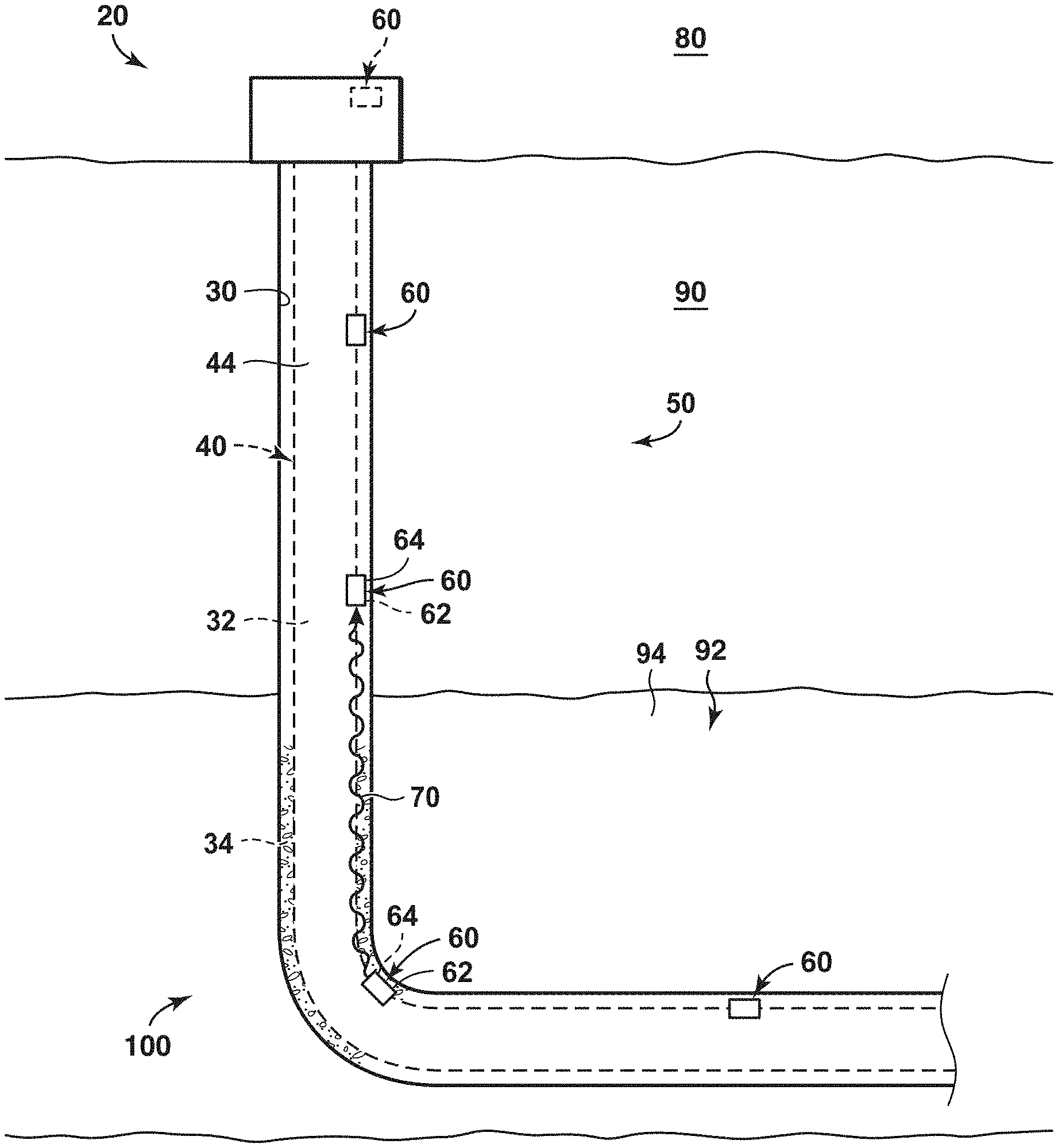
FIG. 1 is a schematic representation of a well configured to use the methods according to the present disclosure.
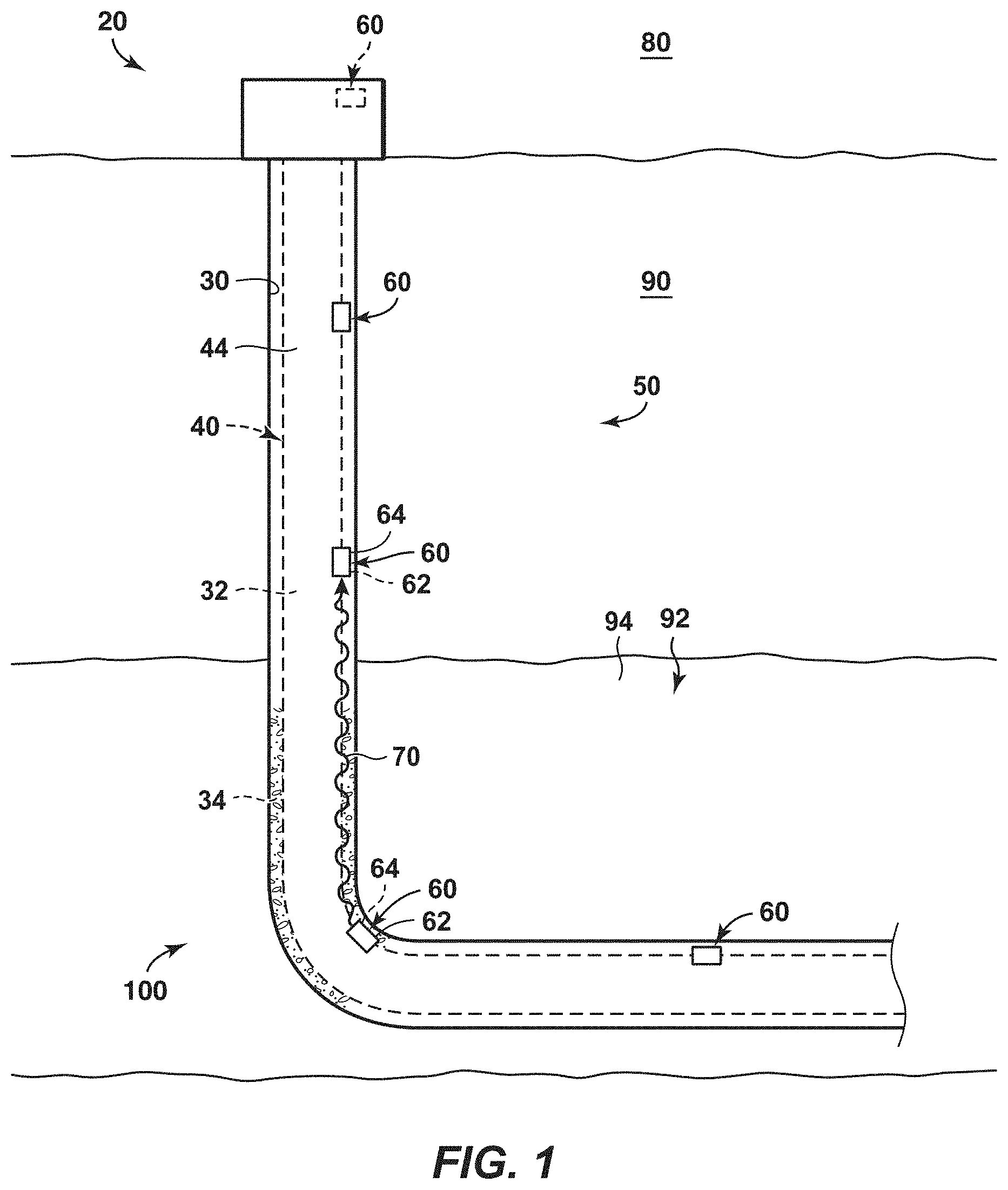
FIG. 2 is a flowchart depicting methods, according to the present disclosure, of determining a major frequency of a received acoustic tone.
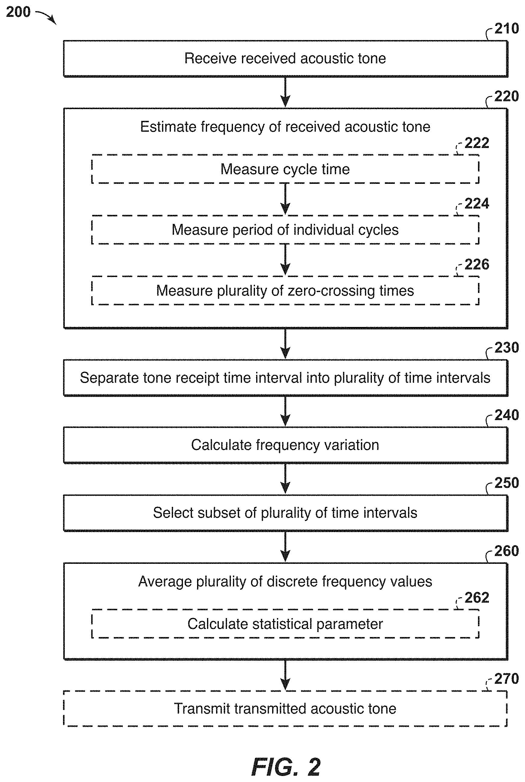
FIG. 3 is a plot illustrating a received amplitude of a plurality of received acoustic tones as a function of time.
FIG. 4 is a plot illustrating a received amplitude of an acoustic tone from FIG. 3.
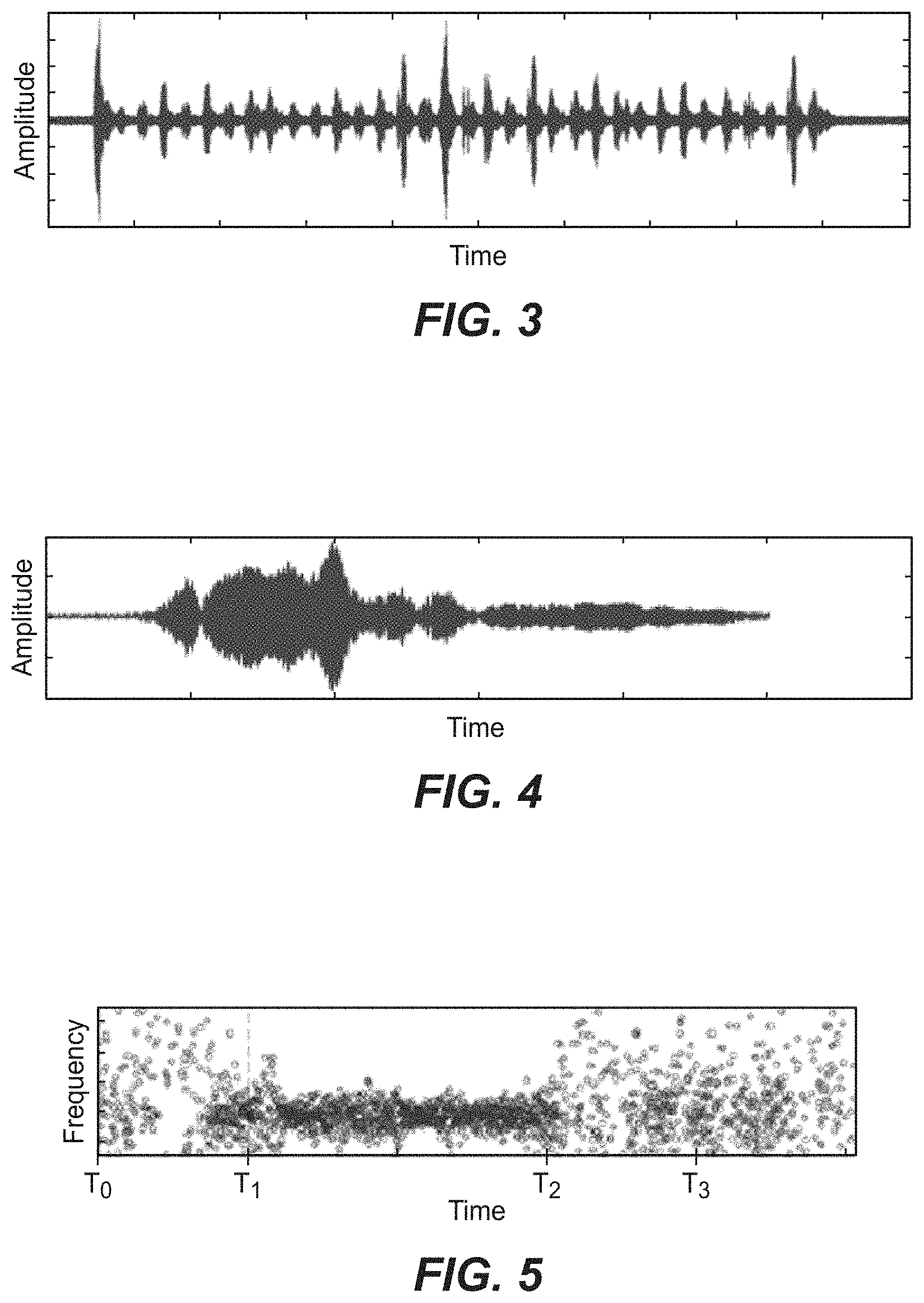
FIG. 5 is a plot illustrating frequency variation in the received acoustic tone of FIG. 4.
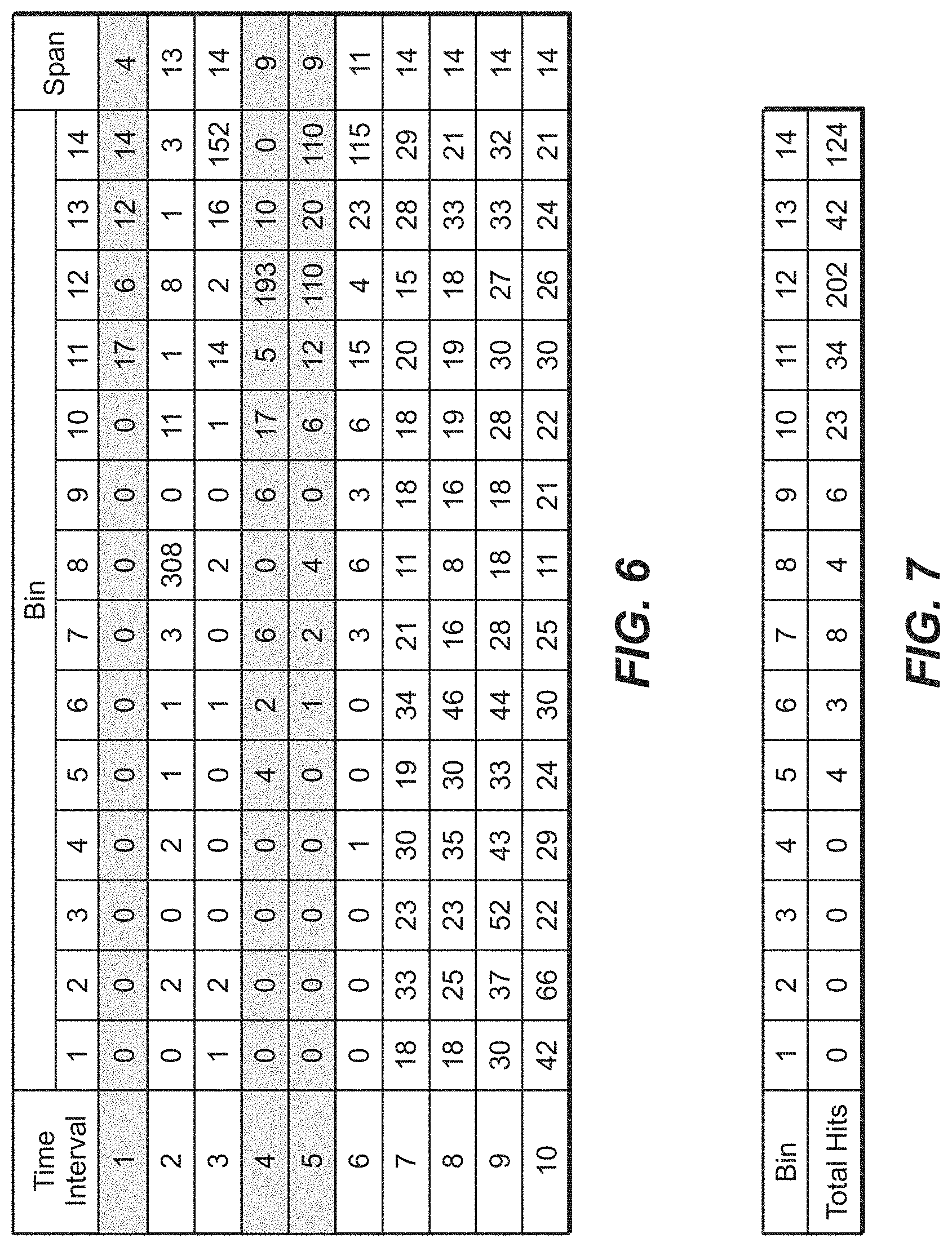
FIG. 6 is a table illustrating histogram data that may be used to determine the major frequency of the received acoustic tone of FIGS. 4-5.
FIG. 7 is a table illustrating a mechanism, according to the present disclosure, by which the major frequency of the acoustic tone of FIGS. 4-5 may be selected.
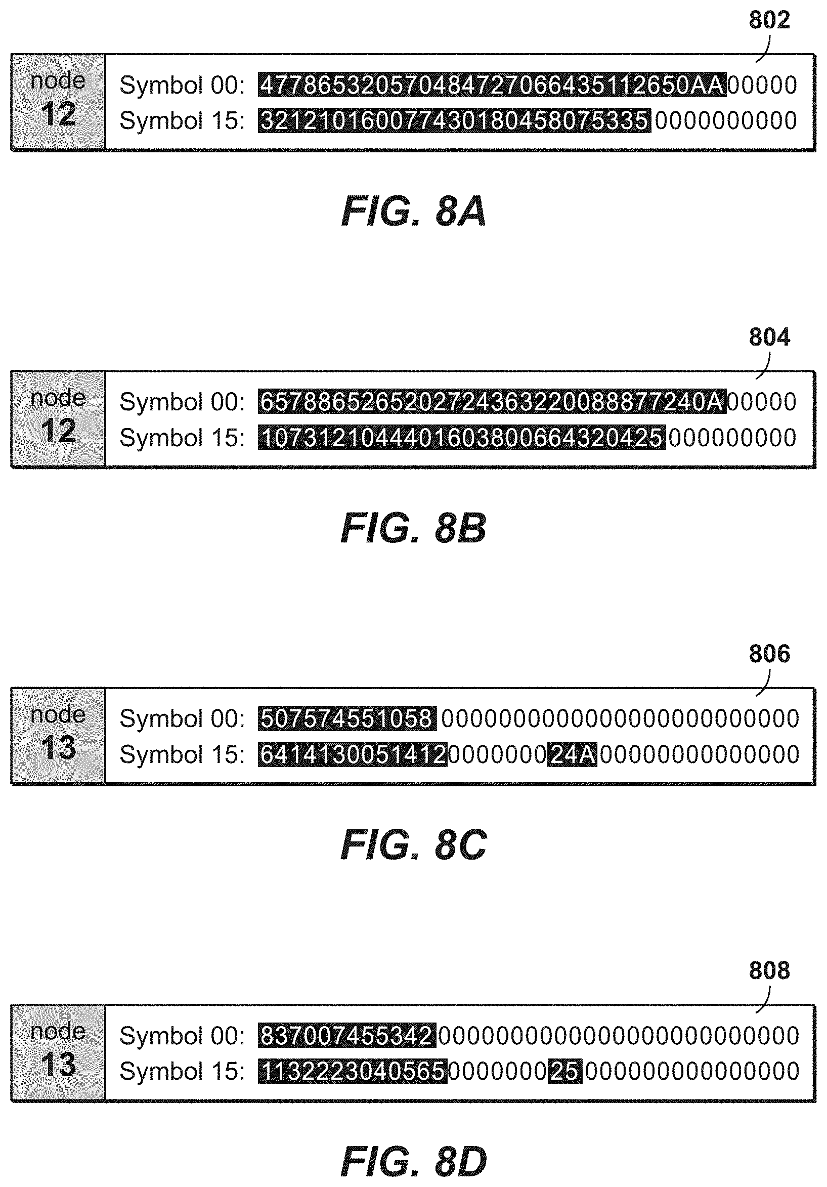
FIGS. 8A-8D depict digital representations of polyhistogram signatures of a received signal.
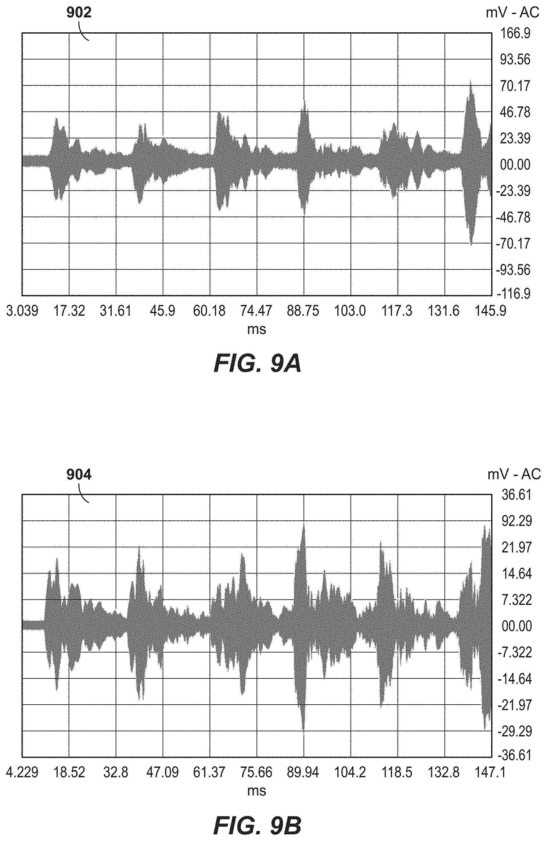
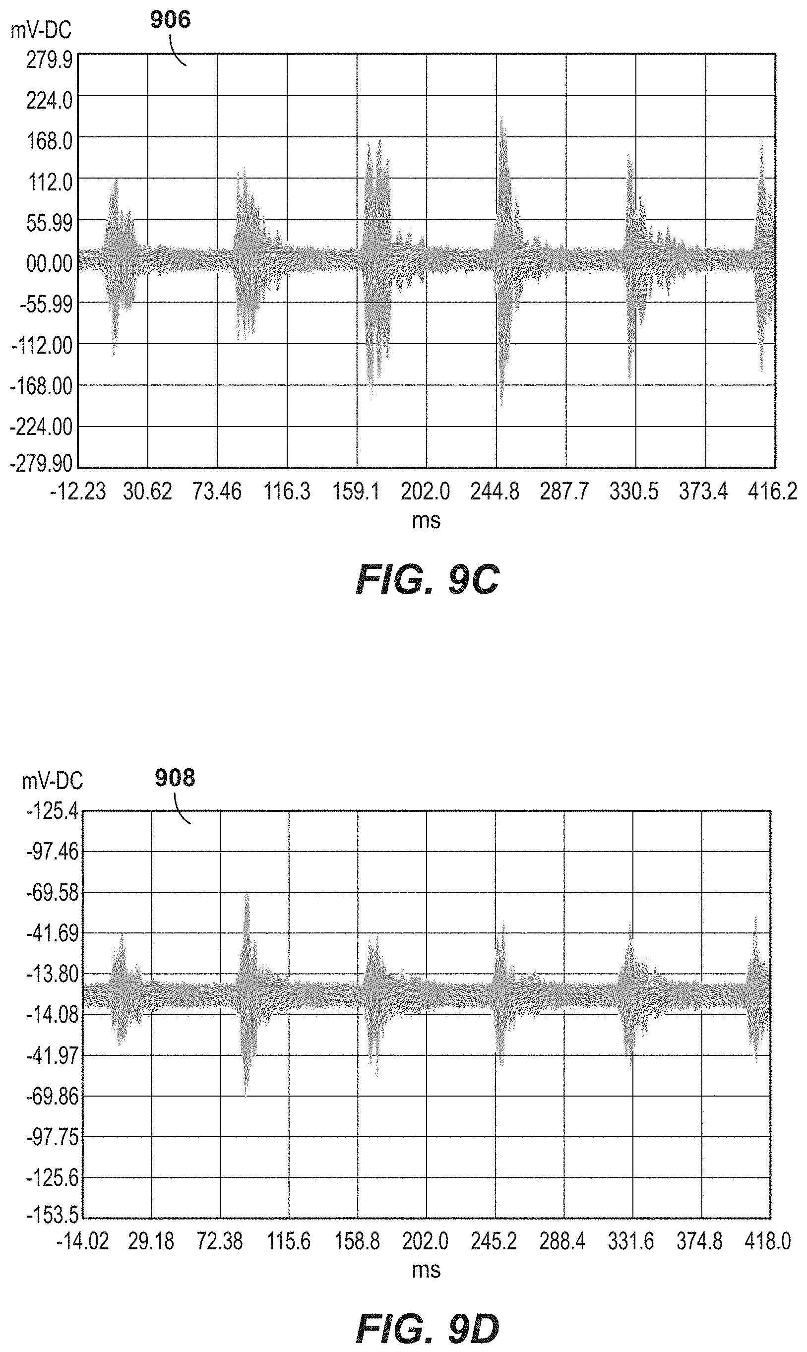
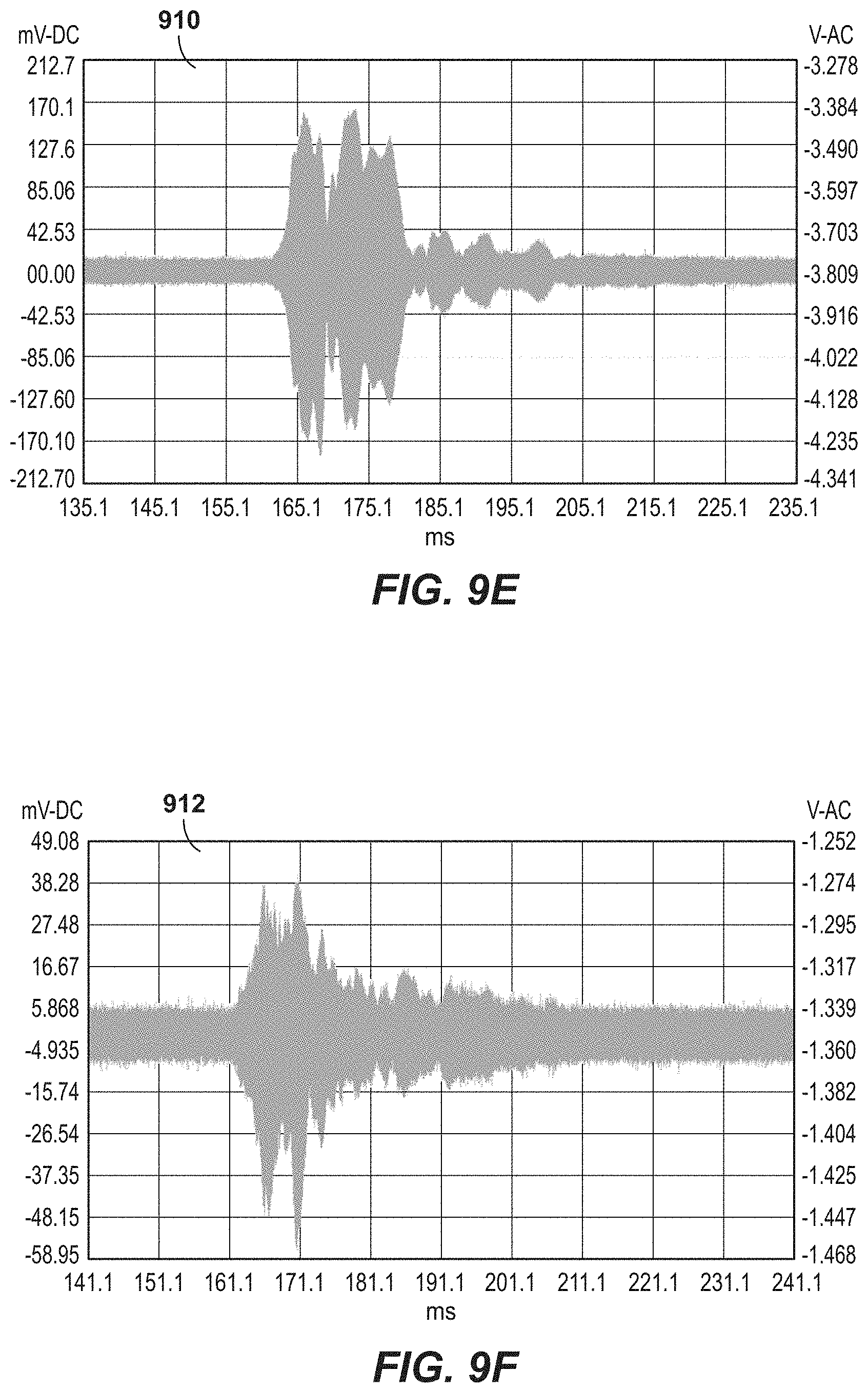
FIGS. 9A-9F are amplitude diagrams showing unique patterns or signatures of a received signal.
FIG. 10 is a flowchart depicting a method of using acoustic tonal signatures as method of network peer identification and self-organization in an acoustic wireless network.
DETAILED DESCRIPTION AND BEST MODE OF THE DISCLOSURE
The following is a non-exhaustive list of definitions of several specific terms used in this disclosure (other terms may be defined or clarified in a definitional manner elsewhere herein). These definitions are intended to clarify the meanings of the terms used herein. It is believed that the terms are used in a manner consistent with their ordinary meaning, but the definitions are nonetheless specified here for clarity.
As used herein, the term "and/or" placed between a first entity and a second entity means one of (1) the first entity, (2) the second entity, and (3) the first entity and the second entity. Multiple entities listed with "and/or" should be construed in the same manner, i.e., "one or more" of the entities so conjoined. Other entities may optionally be present other than the entities specifically identified by the "and/or" clause, whether related or unrelated to those entities specifically identified. Thus, as a non-limiting example, a reference to "A and/or B," when used in conjunction with open-ended language such as "comprising" may refer, in one embodiment, to A only (optionally including entities other than B); in another embodiment, to B only (optionally including entities other than A); in yet another embodiment, to both A and B (optionally including other entities). These entities may refer to elements, actions, structures, steps, operations, values, and the like.
As used herein, the phrase "at least one," in reference to a list of one or more entities should be understood to mean at least one entity selected from any one or more of the entity in the list of entities, but not necessarily including at least one of each and every entity specifically listed within the list of entities and not excluding any combinations of entities in the list of entities. This definition also allows that entities may optionally be present other than the entities specifically identified within the list of entities to which the phrase "at least one" refers, whether related or unrelated to those entities specifically identified. Thus, as a non-limiting example, "at least one of A and B" (or, equivalently, "at least one of A or B," or, equivalently "at least one of A and/or B") may refer, in one embodiment, to at least one, optionally including more than one, A, with no B present (and optionally including entities other than B); in another embodiment, to at least one, optionally including more than one, B, with no A present (and optionally including entities other than A); in yet another embodiment, to at least one, optionally including more than one, A, and at least one, optionally including more than one, B (and optionally including other entities). In other words, the phrases "at least one," "one or more," and "and/or" are open-ended expressions that are both conjunctive and disjunctive in operation. For example, each of the expressions "at least one of A, B and C," "at least one of A, B, or C," "one or more of A, B, and C," "one or more of A, B, or C" and "A, B, and/or C" may mean A alone, B alone, C alone, A and B together, A and C together, B and C together, A, B and C together, and optionally any of the above in combination with at least one other entity.
If any patents, patent applications, or other references are incorporated by reference herein and (1) define a term in a manner that is inconsistent with and/or (2) are otherwise inconsistent with, either the non-incorporated portion of the present disclosure or any of the other incorporated references, the non-incorporated portion of the present disclosure shall control, and the term or incorporated disclosure therein shall only control with respect to the reference in which the term is defined and/or the incorporated disclosure was present originally.
As used herein, the terms "adapted" and "configured" mean that the element, component, or other subject matter is designed and/or intended to perform a given function. Thus, the use of the terms "adapted" and "configured" should not be construed to mean that a given element, component, or other subject matter is simply "capable of" performing a given function but that the element, component, and/or other subject matter is specifically selected, created, implemented, used, programmed, and/or designed for the purpose of performing the function. It is also within the scope of the present disclosure that elements, components, and/or other recited subject matter that is recited as being adapted to perform a particular function may additionally or alternatively be described as being configured to perform that function, and vice versa.
As used herein, the phrase, "for example," the phrase, "as an example," and/or simply the term "example," when used with reference to one or more components, features, details, structures, embodiments, and/or methods according to the present disclosure, are intended to convey that the described component, feature, detail, structure, embodiment, and/or method is an illustrative, non-exclusive example of components, features, details, structures, embodiments, and/or methods according to the present disclosure. Thus, the described component, feature, detail, structure, embodiment, and/or method is not intended to be limiting, required, or exclusive/exhaustive; and other components, features, details, structures, embodiments, and/or methods, including structurally and/or functionally similar and/or equivalent components, features, details, structures, embodiments, and/or methods, are also within the scope of the present disclosure.
As used herein, "fluid" refers to gases, liquids, and combinations of gases and liquids, as well as to combinations of gases and solids, and combinations of liquids and solids.
FIGS. 1-10 provide examples of methods 200 and/or 1000, according to the present disclosure, and/or of wells 20 including acoustic wireless networks 50 that may include and/or use the methods. Elements that serve a similar, or at least substantially similar, purpose are labeled with like numbers in each of FIGS. 1-10, and these elements may not be discussed in detail herein with reference to each of FIGS. 1-10. Similarly, all elements may not be labeled in each of FIGS. 1-10, but reference numerals associated therewith may be used herein for consistency. Elements, components, and/or features that are discussed herein with reference to one or more of FIGS. 1-10 may be included in and/or used with any of FIGS. 1-10 without departing from the scope of the present disclosure. In general, elements that are likely to be included in a particular embodiment are illustrated in solid lines, while elements that are optional are illustrated in dashed lines. However, elements that are shown in solid lines may not be essential and, in some embodiments, may be omitted without departing from the scope of the present disclosure.
FIG. 1 is a schematic representation of a well 20 configured to use methods 200, and/or 1000 according to the present disclosure. Well 20 includes a wellbore 30 that extends within a subsurface region 90. Wellbore 30 also may be referred to herein as extending between a surface region 80 and subsurface region 90 and/or as extending within a subterranean formation 92 that extends within the subsurface region. Subterranean formation 92 may include a hydrocarbon 94. Under these conditions, well 20 also may be referred to herein as, or may be, a hydrocarbon well 20, a production well 20, and/or an injection well 20.
Well 20 also includes an acoustic wireless network 50. The acoustic wireless network also may be referred to herein as a downhole acoustic wireless network 50 and includes a plurality of nodes 60, which are spaced-apart along a tone transmission medium 100 that extends along a length of wellbore 30. In the context of well 20, tone transmission medium 100 may include a downhole tubular 40 that may extend within wellbore 30, a wellbore fluid 32 that may extend within wellbore 30, a portion of subsurface region 90 that is proximal wellbore 30, a portion of subterranean formation 92 that is proximal wellbore 30, and/or a cement 34 that may extend within wellbore 30 and/or that may extend within an annular region between wellbore 30 and downhole tubular 40. Downhole tubular 40 may define a fluid conduit 44.
Nodes 60 may include one or more encoding nodes 62, which may be configured to generate an acoustic tone 70 and/or to induce the acoustic tone within tone transmission medium 100. Nodes 60 also may include one or more decoding nodes 64, which may be configured to receive acoustic tone 70 from the tone transmission medium. A given node 60 may function as both an encoding node 62 and a decoding node 64 depending upon whether the given node is transmitting an acoustic tone (i.e., functioning as the encoding node) or receiving the acoustic tone (i.e., functioning as the decoding node). Stated another way, the given node may include both encoding and decoding functionality, or structures, with these structures being selectively used depending upon whether or not the given node is encoding the acoustic tone or decoding the acoustic tone.
In wells 20, transmission of acoustic tone 70 may be along a length of wellbore 30. As such, the transmission of the acoustic tone may be linear, at least substantially linear, and/or directed, such as by tone transmission medium 100. Such a configuration may be in contrast to more conventional wireless communication methodologies, which generally may transmit a corresponding wireless signal in a plurality of directions, or even in every direction.
FIG. 2 is a flowchart depicting methods 200, according to the present disclosure, of determining a major frequency of a received acoustic tone that is transmitted via a tone transmission medium using histograms generated from the received acoustic tone. Methods 200 may be performed using any suitable structure and/or structures. As an example, methods 200 may be used by an acoustic wireless network, such as acoustic wireless network 50 of FIG. 1. Under these conditions, methods 200 may be used to communicate along a length of wellbore 30.
Methods 200 include receiving a received acoustic tone at 210, estimating a frequency of the received acoustic tone at 220, and separating a tone receipt time into a plurality of time intervals at 230. Methods 200 also include calculating a frequency variation at 240, selecting a subset of the plurality of time intervals at 250, and averaging a plurality of discrete frequency values at 260. Methods 200 further may include transmitting a transmitted acoustic tone at 270.
Receiving the received acoustic tone at 210 may include receiving with a decoding node of an acoustic wireless network. Additionally or alternatively, the receiving at 210 may include receiving from the tone transmission medium and/or receiving for a tone receipt time. The receiving at 210 may include receiving for any suitable tone receipt time. As examples, the tone receipt time may be at least 1 microsecond, at least 10 microseconds, at least 25 microseconds, at least 50 microseconds, at least 75 microseconds, or at least 100 microseconds. The receiving at 210 also may include receiving at any suitable frequency, or tone frequency. Examples of the tone frequency include frequencies of at least 10 kilohertz (kHz), at least 25 kHz, at least 50 kHz, at least 60 kHz, at least 70 kHz, at least 80 kHz, at least 90 kHz, at least 100 kHz, at least 200 kHz, at least 250 kHz, at least 400 kHz, at least 500 kHz, and/or at least 600 kHz. Additionally or alternatively, the tone frequency may be at most 1 megahertz (MHz), at most 800 kHz, at most 600 kHz, at most 400 kHz, at most 200 kHz, at most 150 kHz, at most 100 kHz, and/or at most 80 kHz.
The receiving at 210 may include receiving with any suitable decoding node, such as decoding node 64 of FIG. 1. Additionally or alternatively, the receiving at 210 may include receiving with an acoustic tone receiver. Examples of the acoustic tone receiver include a piezoelectric tone receiver, a piezoresistive tone receiver, a resonant MEMS tone receiver, a non-resonant MEMS tone receiver, and/or a receiver array.
An example of a plurality of received acoustic tones is illustrated in FIG. 3, while an example of a single received acoustic tone is illustrated in FIG. 4. FIGS. 3-4 both illustrate amplitude of the received acoustic tone as a function of time (e.g., the tone receipt time). As illustrated in FIGS. 3-4, the amplitude of the received acoustic tone may vary significantly during the tone receipt time. This variation may be caused by non-idealities within the tone transmission medium and/or with the tone transmission process. Examples of these non-idealities are discussed herein and include acoustic tone reflection points within the tone transmission medium, generation of harmonics during the tone transmission process, ringing within the tone transmission medium, and/or variations in a velocity of the acoustic tone within the tone transmission medium. Collectively, these non-idealities may make it challenging to determine, to accurately determine, and/or to reproducibly determine the major frequency of the received acoustic tone, and methods 200 may facilitate this determination.
Estimating the frequency of the received acoustic tone at 220 may include estimating the frequency of the received acoustic tone as a function of time and/or during the tone receipt time. This may include estimating a plurality of discrete frequency values received at a corresponding plurality of discrete times within the tone receipt time and may be accomplished in any suitable manner.
As an example, the received acoustic tone may include, or be, a received acoustic wave that has a time-varying amplitude within the tone receipt time, as illustrated in FIGS. 3-4. The time-varying amplitude may define an average amplitude, and the estimating at 220 may include measuring a cycle time between the time-varying amplitude and the average amplitude (222), measuring a period of individual cycles of the received acoustic wave (224), and/or measuring a plurality of zero-crossing times of the received acoustic wave (226).
The estimating at 220 may be used to generate a dataset that represents the frequency of the received acoustic tone as a function of time during the tone receipt time. An example of such a dataset is illustrated in FIG. 5. As may be seen in FIG. 5 the frequency of the received acoustic tone includes time regions where there is a relatively higher amount of variation, such as the time regions from T.sub.0 to T.sub.1 and from T.sub.2 to T.sub.3 in FIG. 5, and a time region where there is a relatively lower amount of variation, such as time region from T.sub.1 to T.sub.2 in FIG. 5.
Separating the tone receipt time into the plurality of time intervals at 230 may include separating such that each time interval in the plurality of time intervals includes a subset of the plurality of discrete frequency values that was received and/or determined during that time interval. It is within the scope of the present disclosure that each time interval in the plurality of time intervals may be less than a threshold fraction of the tone receipt time. Examples of the threshold fraction of the tone receipt time include threshold fractions of less than 20%, less than 15%, less than 10%, less than 5%, or less than 1%. Stated another way, the separating at 230 may include separating the tone receipt time into at least a threshold number of time intervals. Examples of the threshold number of time intervals includes at least 5, at least 7, at least 10, at least 20, or at least 100 time intervals. It is within the scope of the present disclosure that a duration of each time interval in the plurality of time intervals may be the same, or at least substantially the same, as a duration of each other time interval in the plurality of time intervals. However, this is not required to all implementations, and the duration of one or more time interval in the plurality of time intervals may differ from the duration of one or more other time intervals in the plurality of time intervals.
Calculating the frequency variation at 240 may include calculating any suitable frequency variation within each time interval and/or within each subset of the plurality of discrete frequency values. The calculating at 240 may be performed in any suitable manner and/or may calculate any suitable measure of variation, or frequency variation. As an example, the calculating at 240 may include calculating a statistical parameter indicative of variability within each subset of the plurality of discrete frequency values. As another example, the calculating at 240 may include calculating a frequency range within each subset of the plurality of discrete frequency values. As yet another example, the calculating at 240 may include calculating a frequency standard deviation of, or within, each subset of the plurality of discrete frequency values. As another example, the calculating at 240 may include scoring each subset of the plurality of discrete frequency values.
As yet another example, the calculating at 240 may include assessing a margin, or assessing the distinctiveness of a given frequency in a given time interval relative to the other frequencies detected during the given time interval. This may include using a magnitude and/or a probability density to assess the distinctiveness and/or using a difference between a magnitude of a most common histogram element and a second most common histogram element within the given time interval to assess the distinctiveness.
As a more specific example, and when the calculating at 240 includes calculating the frequency range, the calculating at 240 may include binning, or separating, each subset of the plurality of discrete frequency values into bins. This is illustrated in FIG. 6. Therein, a number of times that a given frequency (i.e., represented by bins 1-14) is observed within a given time interval (i.e., represented by time intervals 1-10) is tabulated. A zero value for a given frequency bin-time interval combination indicates that the given frequency bin was not observed during the given time interval, while a non-zero number indicates the number of times that the given frequency bin was observed during the given time interval.
Under these conditions, the calculating at 240 may include determining a span, or range, of the frequency bins. In the example of FIG. 6, the uppermost bin that includes at least one count is bin 14, while the lowermost bin that includes at least one count is bin 11. Thus, the span, or range, is 4, as indicated.
Selecting the subset of the plurality of time intervals at 250 may include selecting a subset within which the frequency variation, as determined during the calculating at 240, is less than a threshold frequency variation. Experimental data suggests that time intervals within which the frequency variation is less than the threshold frequency variation represent time intervals that are more representative of the major frequency of the received acoustic tone. As such, the selecting at 250 includes selectively determining which time intervals are more representative of, or more likely to include, the major frequency of the received acoustic tone, thereby decreasing noise in the overall determination of the major frequency of the received acoustic tone.
The selecting at 250 may include selecting a continuous range within the tone receipt time or selecting two or more ranges that are spaced-apart in time within the tone receipt time. Additionally or alternatively, the selecting at 250 may include selecting at least 2, at least 3, at least 4, or at least 5 time intervals from the plurality of time intervals.
The selecting at 250 additionally or alternatively may include selecting such that the frequency variation within each successive subset of the plurality of discrete frequency values decreases relative to a prior subset of the plurality of discrete frequency values and/or remains unchanged relative to the prior subset of the plurality of discrete frequency values.
An example of the selecting at 250 is illustrated in FIG. 6. In this example, time intervals with a span of less than 10 are selected and highlighted in the table. These include time intervals 1, 4, and 5.
Averaging the plurality of discrete frequency values at 260 may include averaging within the subset of the plurality of time intervals that was selected during the selecting at 250 and/or averaging to determine the major frequency of the received acoustic tone. The averaging at 260 may be accomplished in any suitable manner. As an example, the averaging at 260 may include calculating a statistical parameter indicative of an average of the plurality of discrete frequency values within the subset of the plurality of time intervals. As another example, the averaging at 260 may include calculating a mean, median, or mode value of the plurality of discrete frequency values within the subset of the plurality of time intervals.
As a more specific example, and with reference to FIGS. 6-7, the averaging at 260 may include summing the bins for the time intervals that were selected during the selecting at 250. As discussed, and using one criteria for the selecting at 250, bins 1, 4, and 5 from FIG. 6 may be selected. The number of counts in these three bins then may be summed to arrive at FIG. 7, and the bin with the most counts, which represents the most common, or mode, frequency of the selected time intervals, may be selected. In the example of FIG. 7, this may include selecting bin 12, or the frequency of bin 12, as the major frequency of the received acoustic tone.
Transmitting the transmitted acoustic tone at 270 may include transmitting with an encoding node of the acoustic wireless network. The transmitting at 270 may be subsequent, or responsive, to the averaging at 260; and a transmitted frequency of the transmitted acoustic tone may be based, at least in part, on, or equal to, the major frequency of the received acoustic tone. Stated another way, the transmitting at 270 may include repeating, or propagating, the major frequency of the received acoustic tone along the length of the tone transmission medium, such as to permit and/or facilitate communication along the length of the tone transmission medium.
According to an aspect of the disclosure, an acoustic telemetry packet may be sent from node to node along a casing in a wellbore. A node in a fixed location, such as a hydrophone, may listen to the telemetry progress down the acoustic wireless network and a representation of the received acoustic signal may be recorded. This representation is known colloquially as a histogram or polyhistogram and may be generated as previously disclosed, or by collecting zero-crossings interpreted in time bins, such as 1 millisecond-long bins, by a receiver algorithm when receiving a telemetry packet. Other means of analyzing the frequency and/or amplitude of a received acoustic signal may be used, such as: performing a Fourier transform of the received acoustic signal; performing a fast Fourier transform (FFT) of the received acoustic signal; performing a discrete Fourier transform of the received acoustic signal; performing a wavelet transform of the received acoustic signal; performing a multiple least squares analysis of the received acoustic signal; margin, span with zero crossing rate to (ZCR); margin, span with Fast Fourier Transforms (FFT), and the like. The process of identifying frequencies in a wireless network using histograms is described in co-pending and commonly owned U.S. Patent Application Publication No. 2018/058,204,
References
D00000
D00001
D00002
D00003
D00004
D00005
D00006
D00007
D00008
D00009
XML
uspto.report is an independent third-party trademark research tool that is not affiliated, endorsed, or sponsored by the United States Patent and Trademark Office (USPTO) or any other governmental organization. The information provided by uspto.report is based on publicly available data at the time of writing and is intended for informational purposes only.
While we strive to provide accurate and up-to-date information, we do not guarantee the accuracy, completeness, reliability, or suitability of the information displayed on this site. The use of this site is at your own risk. Any reliance you place on such information is therefore strictly at your own risk.
All official trademark data, including owner information, should be verified by visiting the official USPTO website at www.uspto.gov. This site is not intended to replace professional legal advice and should not be used as a substitute for consulting with a legal professional who is knowledgeable about trademark law.