Plunger lift monitoring via a downhole wireless network field
Romer , et al.
U.S. patent number 10,697,287 [Application Number 15/665,952] was granted by the patent office on 2020-06-30 for plunger lift monitoring via a downhole wireless network field. This patent grant is currently assigned to ExxonMobil Upstream Research Company. The grantee listed for this patent is Timothy I. Morrow, Michael C. Romer, Randy C. Tolman. Invention is credited to Timothy I. Morrow, Michael C. Romer, Randy C. Tolman.


| United States Patent | 10,697,287 |
| Romer , et al. | June 30, 2020 |
Plunger lift monitoring via a downhole wireless network field
Abstract
A real-time system for monitoring plunger properties in a gas producing well is provided. The system includes a plunger comprising a substantially cylindrical body; at least one sensor disposed along a tubular body; at least one sensor communications node placed along the tubular body and affixed to a wall of the tubular body, the sensor communications node being in electrical communication with the at least one sensor and configured to receive signals therefrom; a topside communications node placed proximate a surface; a plurality of intermediate communications nodes spaced along the tubular body and attached to a wall of the tubular body; wherein the intermediate communications nodes are configured to transmit signals received from the at least one sensor communications node to the topside communications node in substantially a node-to-node arrangement; a receiver at the surface configured to receive signals from the topside communications node; and a plunger control system structured and arranged to communicate with the topside communications node. A method of monitoring plunger properties and controlling plunger performance, and a hydrocarbon well are also provided.
| Inventors: | Romer; Michael C. (The Woodlands, TX), Tolman; Randy C. (Spring, TX), Morrow; Timothy I. (Humble, TX) | ||||||||||
|---|---|---|---|---|---|---|---|---|---|---|---|
| Applicant: |
|
||||||||||
| Assignee: | ExxonMobil Upstream Research
Company (Spring, TX) |
||||||||||
| Family ID: | 61240356 | ||||||||||
| Appl. No.: | 15/665,952 | ||||||||||
| Filed: | August 1, 2017 |
Prior Publication Data
| Document Identifier | Publication Date | |
|---|---|---|
| US 20180058191 A1 | Mar 1, 2018 | |
Related U.S. Patent Documents
| Application Number | Filing Date | Patent Number | Issue Date | ||
|---|---|---|---|---|---|
| 62381926 | Aug 31, 2016 | ||||
| 62381330 | Aug 30, 2016 | ||||
| 62381335 | Aug 30, 2016 | ||||
| 62428367 | Nov 30, 2016 | ||||
| 62428374 | Nov 30, 2016 | ||||
| 62428385 | Nov 30, 2016 | ||||
| 62433491 | Dec 13, 2016 | ||||
| 62428425 | Nov 30, 2016 | ||||
| Current U.S. Class: | 1/1 |
| Current CPC Class: | E21B 47/13 (20200501); E21B 47/135 (20200501); E21B 47/14 (20130101); E21B 43/122 (20130101); E21B 47/06 (20130101); E21B 49/08 (20130101); E21B 47/09 (20130101); G01V 1/44 (20130101); E21B 47/008 (20200501); E21B 43/121 (20130101); E21B 41/02 (20130101); E21B 37/06 (20130101); G01V 1/22 (20130101); E21B 47/017 (20200501); G01V 1/52 (20130101) |
| Current International Class: | E21B 43/12 (20060101); E21B 47/00 (20120101); E21B 47/008 (20120101); E21B 47/09 (20120101); E21B 49/08 (20060101); E21B 47/06 (20120101); G01V 1/44 (20060101); E21B 47/13 (20120101); E21B 47/135 (20120101); E21B 47/14 (20060101); E21B 41/02 (20060101); E21B 37/06 (20060101); G01V 1/52 (20060101); G01V 1/22 (20060101); E21B 47/017 (20120101) |
References Cited [Referenced By]
U.S. Patent Documents
| 3103643 | September 1963 | Kalbfell |
| 3205477 | September 1965 | Kalbfell |
| 3512407 | May 1970 | Zill |
| 3637010 | January 1972 | Malay et al. |
| 3741301 | June 1973 | Malay et al. |
| 3781783 | December 1973 | Tucker |
| 3790930 | February 1974 | Lamel et al. |
| 3900827 | August 1975 | Lamel et al. |
| 3906434 | September 1975 | Lamel et al. |
| 4001773 | January 1977 | Lamel et al. |
| 4283780 | August 1981 | Nardi |
| 4298970 | November 1981 | Shawhan et al. |
| 4302826 | November 1981 | Kent et al. |
| 4314365 | February 1982 | Peterson et al. |
| 4884071 | November 1989 | Howard |
| 4962489 | October 1990 | Medlin et al. |
| 5128901 | July 1992 | Drumheller |
| 5136613 | August 1992 | Dumestre, III |
| 5166908 | November 1992 | Montgomery |
| 5182946 | February 1993 | Boughner et al. |
| 5234055 | August 1993 | Cornette |
| 5283768 | February 1994 | Rorden |
| 5373481 | December 1994 | Orban et al. |
| 5468025 | November 1995 | Adinolfe et al. |
| 5480201 | January 1996 | Mercer |
| 5495230 | February 1996 | Lian |
| 5562240 | October 1996 | Campbell |
| 5592438 | January 1997 | Rorden et al. |
| 5667650 | September 1997 | Face et al. |
| 5850369 | December 1998 | Rorden et al. |
| 5857146 | January 1999 | Kido |
| 5924499 | July 1999 | Birchak et al. |
| 5960883 | October 1999 | Tubel et al. |
| 5995449 | November 1999 | Green et al. |
| 6049508 | April 2000 | Deflandre |
| 6125080 | September 2000 | Sonnenschein et al. |
| 6128250 | October 2000 | Reid et al. |
| 6177882 | January 2001 | Ringgenberg et al. |
| 6236850 | May 2001 | Desai |
| 6239690 | May 2001 | Burbidge et al. |
| 6300743 | October 2001 | Patino et al. |
| 6320820 | November 2001 | Gardner et al. |
| 6324904 | December 2001 | Ishikawa et al. |
| 6360769 | March 2002 | Brisco |
| 6394184 | May 2002 | Tolman et al. |
| 6400646 | June 2002 | Shah et al. |
| 6429784 | August 2002 | Beique et al. |
| 6462672 | October 2002 | Besson |
| 6543538 | April 2003 | Tolman et al. |
| 6670880 | December 2003 | Hall et al. |
| 6679332 | January 2004 | Vinegar et al. |
| 6695277 | February 2004 | Gallis |
| 6702019 | March 2004 | Dusterhoft et al. |
| 6717501 | April 2004 | Hall et al. |
| 6727827 | April 2004 | Edwards et al. |
| 6772837 | August 2004 | Dusterhoft et al. |
| 6816082 | November 2004 | Laborde |
| 6868037 | March 2005 | Dasgupta et al. |
| 6880634 | April 2005 | Gardner et al. |
| 6883608 | April 2005 | Parlar et al. |
| 6899178 | May 2005 | Tubel |
| 6909667 | June 2005 | Shah et al. |
| 6912177 | June 2005 | Smith |
| 6920085 | July 2005 | Finke et al. |
| 6930616 | August 2005 | Tang et al. |
| 6940392 | September 2005 | Chan et al. |
| 6940420 | September 2005 | Jenkins |
| 6953094 | October 2005 | Ross et al. |
| 6956791 | October 2005 | Dopf et al. |
| 6980929 | December 2005 | Aronstam et al. |
| 6987463 | January 2006 | Beique et al. |
| 7006918 | February 2006 | Economides et al. |
| 7011157 | March 2006 | Costley et al. |
| 7036601 | May 2006 | Berg et al. |
| 7051812 | May 2006 | McKee et al. |
| 7064676 | June 2006 | Hall et al. |
| 7082993 | August 2006 | Ayoub et al. |
| 7090020 | August 2006 | Hill et al. |
| 7140434 | November 2006 | Chouzenoux et al. |
| 7219762 | May 2007 | James et al. |
| 7224288 | May 2007 | Hall et al. |
| 7228902 | June 2007 | Oppelt |
| 7249636 | July 2007 | Ohmer |
| 7217050 | August 2007 | Stewart et al. |
| 7252152 | August 2007 | LoGiudice et al. |
| 7261154 | August 2007 | Hall et al. |
| 7261162 | August 2007 | Deans et al. |
| 7275597 | October 2007 | Hall et al. |
| 7277026 | October 2007 | Hall et al. |
| RE40032 | January 2008 | van Borkhorst et al. |
| 7317990 | January 2008 | Sinha et al. |
| 7321788 | January 2008 | Addy et al. |
| 7322416 | January 2008 | Burris, II et al. |
| 7325605 | February 2008 | Fripp et al. |
| 7339494 | March 2008 | Shah et al. |
| 7348593 | March 2008 | Huang et al. |
| 7385523 | June 2008 | Thomeer et al. |
| 7387165 | June 2008 | Lopez de Cardenas et al. |
| 7411517 | August 2008 | Flanagan |
| 7477160 | January 2009 | Lemenager et al. |
| 7516792 | April 2009 | Lonnes et al. |
| 7551057 | June 2009 | King et al. |
| 7590029 | September 2009 | Tingley |
| 7595737 | September 2009 | Fink et al. |
| 7602668 | October 2009 | Liang et al. |
| 7649473 | January 2010 | Johnson et al. |
| 7750808 | July 2010 | Masino et al. |
| 7775279 | August 2010 | Marya et al. |
| 7787327 | August 2010 | Tang et al. |
| 7819188 | October 2010 | Auzerais et al. |
| 7828079 | November 2010 | Oothoudt |
| 7831283 | November 2010 | Ogushi et al. |
| 7913773 | March 2011 | Li et al. |
| 7952487 | May 2011 | Montebovi |
| 7994932 | August 2011 | Huang et al. |
| 8004421 | August 2011 | Clark |
| 8044821 | October 2011 | Mehta |
| 8049506 | November 2011 | Lazarev |
| 8115651 | February 2012 | Camwell et al. |
| 8117907 | February 2012 | Han et al. |
| 8157008 | April 2012 | Lilley |
| 8162050 | April 2012 | Roddy et al. |
| 8220542 | July 2012 | Whitsitt et al. |
| 8237585 | August 2012 | Zimmerman |
| 8242928 | August 2012 | Prammer |
| 8276674 | October 2012 | Lopez de Cardenas et al. |
| 8284075 | October 2012 | Fincher et al. |
| 8284947 | October 2012 | Giesbrecht et al. |
| 8316936 | November 2012 | Roddy et al. |
| 8330617 | December 2012 | Chen et al. |
| 8347982 | January 2013 | Hannegan et al. |
| 8358220 | January 2013 | Savage |
| 8376065 | February 2013 | Teodorescu et al. |
| 8381822 | February 2013 | Hales et al. |
| 8388899 | March 2013 | Mitani et al. |
| 8411530 | April 2013 | Slocum et al. |
| 8434354 | May 2013 | Crow et al. |
| 8494070 | July 2013 | Luo et al. |
| 8496055 | July 2013 | Mootoo et al. |
| 8539890 | September 2013 | Tripp et al. |
| 8544564 | October 2013 | Moore et al. |
| 8552597 | October 2013 | Song et al. |
| 8556302 | October 2013 | Dole |
| 8559272 | October 2013 | Wang |
| 8596359 | December 2013 | Grigsby et al. |
| 8605548 | December 2013 | Froelich |
| 8607864 | December 2013 | Mcleod et al. |
| 8664958 | March 2014 | Simon |
| 8672875 | March 2014 | Vanderveen et al. |
| 8675779 | March 2014 | Zeppetelle et al. |
| 8683859 | April 2014 | Godager |
| 8689621 | April 2014 | Godager |
| 8701480 | April 2014 | Eriksen |
| 8750789 | June 2014 | Baldemair et al. |
| 8787840 | July 2014 | Srinivasan et al. |
| 8805632 | August 2014 | Coman et al. |
| 8826980 | September 2014 | Neer |
| 8833469 | September 2014 | Purkis |
| 8893784 | November 2014 | Abad |
| 8910716 | December 2014 | Newton et al. |
| 8994550 | March 2015 | Millot et al. |
| 8995837 | March 2015 | Mizuguchi et al. |
| 9062508 | June 2015 | Huval et al. |
| 9062531 | June 2015 | Jones |
| 9075155 | July 2015 | Luscombe et al. |
| 9078055 | July 2015 | Nguyen et al. |
| 9091153 | July 2015 | Yang et al. |
| 9133705 | September 2015 | Angeles Boza |
| 9140097 | September 2015 | Themig et al. |
| 9144894 | September 2015 | Barnett et al. |
| 9206645 | December 2015 | Hallundbaek |
| 9279301 | March 2016 | Lovorn et al. |
| 9284819 | March 2016 | Tolman et al. |
| 9284834 | March 2016 | Alteirac et al. |
| 9310510 | April 2016 | Godager |
| 9331696 | May 2016 | Hay |
| 9333350 | May 2016 | Rise et al. |
| 9359841 | June 2016 | Hall |
| 9363605 | June 2016 | Goodman et al. |
| 9376908 | June 2016 | Ludwig et al. |
| 9441470 | September 2016 | Guerrero et al. |
| 9515748 | December 2016 | Jeong et al. |
| 9557434 | January 2017 | Keller et al. |
| 9617829 | April 2017 | Dale et al. |
| 9617850 | April 2017 | Fripp et al. |
| 9631485 | April 2017 | Keller et al. |
| 9657564 | May 2017 | Stolpman |
| 9664013 | May 2017 | Logan et al. |
| 9670773 | June 2017 | Croux |
| 9683434 | June 2017 | Machocki |
| 9686021 | June 2017 | Merino |
| 9715031 | July 2017 | Contant et al. |
| 9721448 | August 2017 | Wu et al. |
| 9759062 | September 2017 | Deffenbaugh et al. |
| 9816373 | November 2017 | Howell et al. |
| 9822634 | November 2017 | Gao |
| 9863222 | January 2018 | Morrow et al. |
| 9879525 | January 2018 | Morrow et al. |
| 9945204 | April 2018 | Ross et al. |
| 9963955 | May 2018 | Tolman et al. |
| 10100635 | October 2018 | Keller et al. |
| 10103846 | October 2018 | Van Zelm et al. |
| 10132149 | November 2018 | Morrow et al. |
| 10145228 | December 2018 | Yarus et al. |
| 10167716 | January 2019 | Clawson et al. |
| 10167717 | January 2019 | Disko et al. |
| 10190410 | January 2019 | Clawson et al. |
| 10196862 | February 2019 | Li-Leger et al. |
| 2002/0180613 | December 2002 | Shi et al. |
| 2003/0056953 | March 2003 | Tumlin et al. |
| 2003/0117896 | June 2003 | Sakuma et al. |
| 2004/0020063 | February 2004 | Lewis et al. |
| 2004/0200613 | October 2004 | Fripp et al. |
| 2004/0239521 | December 2004 | Zierolf |
| 2005/0269083 | December 2005 | Burris et al. |
| 2005/0284659 | December 2005 | Hall et al. |
| 2006/0033638 | February 2006 | Hall |
| 2006/0041795 | February 2006 | Gabelmann et al. |
| 2006/0054329 | March 2006 | Chisholm |
| 2006/0090893 | May 2006 | Sheffield |
| 2007/0139217 | June 2007 | Beique et al. |
| 2007/0146351 | June 2007 | Katsurahira et al. |
| 2007/0156359 | July 2007 | Varsamis et al. |
| 2007/0219758 | September 2007 | Bloomfield |
| 2007/0272411 | November 2007 | Lopez de Cardenas et al. |
| 2008/0030365 | February 2008 | Fripp et al. |
| 2008/0110644 | May 2008 | Howell et al. |
| 2008/0185144 | August 2008 | Lovell |
| 2008/0304360 | December 2008 | Mozer |
| 2009/0003133 | January 2009 | Dalton et al. |
| 2009/0030614 | January 2009 | Carnegie et al. |
| 2009/0034368 | February 2009 | Johnson |
| 2009/0045974 | February 2009 | Patel |
| 2009/0080291 | March 2009 | Tubel et al. |
| 2009/0166031 | July 2009 | Hernandez |
| 2010/0013663 | January 2010 | Cavender et al. |
| 2010/0089141 | April 2010 | Rioufol et al. |
| 2010/0133004 | June 2010 | Burleson et al. |
| 2010/0182161 | July 2010 | Robbins et al. |
| 2010/0212891 | August 2010 | Stewart et al. |
| 2011/0061862 | March 2011 | Loretz et al. |
| 2011/0066378 | March 2011 | Lerche et al. |
| 2011/0168403 | July 2011 | Patel |
| 2011/0188345 | August 2011 | Wang |
| 2011/0297376 | December 2011 | Holderman et al. |
| 2011/0297673 | December 2011 | Zbat et al. |
| 2011/0301439 | December 2011 | Albert et al. |
| 2011/0315377 | December 2011 | Rioufol |
| 2012/0043079 | February 2012 | Wassouf et al. |
| 2012/0126992 | May 2012 | Rodney et al. |
| 2012/0152562 | June 2012 | Newton et al. |
| 2012/0179377 | July 2012 | Lie |
| 2013/0000981 | January 2013 | Grimmer et al. |
| 2013/0003503 | January 2013 | L'Her et al. |
| 2013/0106615 | May 2013 | Prammer |
| 2013/0138254 | May 2013 | Seals et al. |
| 2013/0192823 | August 2013 | Barrilleaux et al. |
| 2013/0248172 | September 2013 | Angeles Boza et al. |
| 2013/0278432 | October 2013 | Shashoua et al. |
| 2013/0319102 | December 2013 | Riggenberg et al. |
| 2014/0060840 | March 2014 | Hartshorne et al. |
| 2014/0062715 | March 2014 | Clark |
| 2014/0102708 | April 2014 | Purkis et al. |
| 2014/0133276 | May 2014 | Volker et al. |
| 2014/0152659 | June 2014 | Davidson et al. |
| 2014/0153368 | June 2014 | Bar-Cohen et al. |
| 2014/0166266 | June 2014 | Read |
| 2014/0170025 | June 2014 | Weiner et al. |
| 2014/0266769 | September 2014 | van Zelm |
| 2014/0327552 | November 2014 | Filas et al. |
| 2014/0352955 | December 2014 | Tubel et al. |
| 2015/0003202 | January 2015 | Palmer et al. |
| 2015/0009040 | January 2015 | Bowles et al. |
| 2015/0027687 | January 2015 | Tubel |
| 2015/0041124 | February 2015 | Rodriguez |
| 2015/0041137 | February 2015 | Rodriguez |
| 2015/0152727 | June 2015 | Fripp et al. |
| 2015/0159481 | June 2015 | Mebarkia et al. |
| 2015/0167425 | June 2015 | Hammer et al. |
| 2015/0176370 | June 2015 | Greening et al. |
| 2015/0292319 | October 2015 | Disko et al. |
| 2015/0292320 | October 2015 | Lynk et al. |
| 2015/0292321 | October 2015 | Keller |
| 2015/0300159 | October 2015 | Stiles et al. |
| 2015/0330200 | November 2015 | Richard et al. |
| 2015/0337642 | November 2015 | Spacek |
| 2015/0354351 | December 2015 | Morrow et al. |
| 2015/0377016 | December 2015 | Ahmad |
| 2016/0010446 | January 2016 | Logan et al. |
| 2016/0047230 | February 2016 | Livescu et al. |
| 2016/0047233 | February 2016 | Butner et al. |
| 2016/0076363 | March 2016 | Morrow et al. |
| 2016/0109606 | April 2016 | Market et al. |
| 2016/0215612 | July 2016 | Morrow |
| 2017/0138185 | May 2017 | Saed et al. |
| 2017/0145811 | May 2017 | Robison et al. |
| 2017/0152741 | June 2017 | Park et al. |
| 2017/0167249 | June 2017 | Lee et al. |
| 2017/0204719 | July 2017 | Babakhani |
| 2017/0254183 | September 2017 | Vasques et al. |
| 2017/0293044 | October 2017 | Gilstrap et al. |
| 2017/0314386 | November 2017 | Orban et al. |
| 2018/0010449 | January 2018 | Roberson |
| 2018/0058191 | March 2018 | Romer et al. |
| 2018/0058198 | March 2018 | Ertas et al. |
| 2018/0058202 | March 2018 | Disko et al. |
| 2018/0058203 | March 2018 | Clawson et al. |
| 2018/0058204 | March 2018 | Clawson et al. |
| 2018/0058205 | March 2018 | Clawson et al. |
| 2018/0058206 | March 2018 | Zhang et al. |
| 2018/0058207 | March 2018 | Song et al. |
| 2018/0058208 | March 2018 | Song et al. |
| 2018/0058209 | March 2018 | Song et al. |
| 2018/0066490 | March 2018 | Kjos |
| 2018/0066510 | March 2018 | Walker et al. |
| 102733799 | Jun 2014 | CN | |||
| 0636763 | Feb 1995 | EP | |||
| 1409839 | Apr 2005 | EP | |||
| 2677698 | Dec 2013 | EP | |||
| WO2002/027139 | Apr 2002 | WO | |||
| WO2010/074766 | Jul 2010 | WO | |||
| WO2013/079928 | Jun 2013 | WO | |||
| WO 2013/079928 | Jun 2013 | WO | |||
| WO 2013/112273 | Aug 2013 | WO | |||
| WO2014/018010 | Jan 2014 | WO | |||
| WO 2014/018010 | Jan 2014 | WO | |||
| WO2014/049360 | Apr 2014 | WO | |||
| WO 2014/049360 | Apr 2014 | WO | |||
| WO2014/100271 | Jun 2014 | WO | |||
| WO2014/134741 | Sep 2014 | WO | |||
| WO 2014/134741 | Sep 2014 | WO | |||
| WO2015/117060 | Aug 2015 | WO | |||
Other References
|
US. Appl. No. 15/666,334, filed Aug. 1, 2017, Walker, Katie M. et al. cited by applicant . U.S. Appl. No. 16/139,373, filed Sep. 24, 2018, Yi, Xiaohua et al. cited by applicant . U.S. Appl. No. 16/139,384, filed Oct. 13, 2017, Disko, Mark M. et al. cited by applicant . U.S. Appl. No. 16/139,394, filed Oct. 13, 2017, Song, Limin et al. cited by applicant . U.S. Appl. No. 16/394,403, filed Oct. 13, 2017, Song, Limin et al. cited by applicant . U.S. Appl. No. 16/139414, filed Oct. 13, 2017, Zhang, Yibing et al. cited by applicant . U.S. Appl. No. 16/139421, filed Oct. 13, 2017, Song, Limin et al. cited by applicant . U.S. Appl. No. 16/139,427, filed Oct. 13, 2017, Disko, Mark M. et al. cited by applicant . U.S. Appl. No. 16/175418, filed Oct. 30, 2018, Kent, David K. et al. cited by applicant . U.S. Appl. No. 62/588067, filed Nov. 17, 2017, Song, Limin et al. cited by applicant . U.S. Appl. No. 62/588080, filed Nov. 17, 2017, Kinn, Timothy F. et al. cited by applicant . U.S. Appl. No. 62/588103, filed Nov. 17, 2017, Yi, Xiaohua et al. cited by applicant . Arroyo, Javier et al. (2009) "Forecasting Histogram Time Series with K-Nearest Neighbours Methods," International Journal of Forecasting, v.25, pp. 192-207. cited by applicant . Arroyo, Javier et al. (2011) "Smoothing Methods for Histogram-Valued Time Seriers: An Application to Value-at-Risk," Univ. of California, Dept. of Economics, www.wileyonlinelibrary.com, Mar. 8, 2011, 28 pages. cited by applicant . Arroyo, Javier et al. (2011) "Forecasting with Interval and Histogram Data Some Financial Applications," Univ. of California, Dept. of Economics, 46 pages. cited by applicant . Emerson Process Management (2011), "Roxar downhole Wireless PT sensor system," www.roxar.com or downhole@roxar.com, 2 pgs. cited by applicant . Gonzalez-Rivera, Gloria et al. (2012) "Time Series Modeling of Histogram-Valued Data: The Daily Histogram Time Series of S&P500 Intradaily Returns," International Journal of Forecasting, v.28, 36 pgs. cited by applicant . Gutierrez-Estevez, M. A. et al. (2013) "Acoustic Boardband Communications Over Deep Drill Strings using Adaptive OFDM", IEEE Wireless Comm. & Networking Conf., pp. 4089-4094. cited by applicant . Qu, X. et al. (2011) "Reconstruction fo Self-Sparse 20 NMR Spectra From undersampled Data In The Indirect Dimension", pp. 8888-8909. cited by applicant . U.S. Department of Defense (1999) "Interoperability and Performance Standards for Medium and High Frequency Radio Systems," MIL-STD-188-141B, Mar. 1, 1999, 584 pages. cited by applicant. |
Primary Examiner: Wright; Giovanna
Assistant Examiner: Akaragwe; Yanick A
Attorney, Agent or Firm: ExxonMobil Upstream Research Company--Law Department
Parent Case Text
CROSS REFERENCE TO RELATED APPLICATION
This application claims the benefit of U.S. Provisional Application Ser. No. 62/381,926 filed on Aug. 31, 2016, entitled "Plunger Lift Monitoring Via a Downhole Wireless Network Field," U.S. Provisional Application Ser. No. 62/381,330 filed Aug. 30, 2016, entitled "Communication Networks, Relay Nodes for Communication Networks, and Methods of Transmitting Data Among a Plurality of Relay Nodes," U.S. Provisional Application Ser. No. 62/381,335, filed Aug. 30, 2016 entitled "Zonal Isolation Devices Including Sensing and Wireless Telemetry and Methods of Utilizing the Same," U.S. Provisional Application Ser. No. 62/428,367, filed Nov. 30, 2016, entitled "Dual Transducer Communications Node for Downhole Acoustic Wireless Networks and Method Employing Same," U.S. Provisional Application Ser. No. 62/428,374, filed Nov. 30, 2016, entitled "Hybrid Downhole Acoustic Wireless Network," U.S. Provisional Application Ser. No. 62/428,385, filed Nov. 30, 2016 entitled "Methods of Acoustically Communicating And Wells That Utilize The Methods," U.S. Provisional Application Ser. No. 62/433,491, filed Dec. 13, 2016 entitled "Methods of Acoustically Communicating And Wells That Utilize The Methods," and U.S. Provisional Application Ser. No. 62/428,425 filed Nov. 30, 2016, entitled "Acoustic Housing for Tubulars," the disclosures of which are incorporated herein by reference in their entireties.
Claims
What is claimed is:
1. A real-time system for monitoring plunger properties in a gas producing well, comprising: at least one sensor disposed along a tubular body; a plunger located and conveyed within the tubular body,the plunger comprising a substantially cylindrical body; at least one sensor communications node placed along the tubular body and affixed to a wall of the tubular body, the sensor communications node being in electrical communication with the at least one sensor and configured to receive signals therefrom; a topside communications node placed proximate a surface; a plurality of intermiediate communications nodes spaced along the tubular body and attached to the wall of the tubular body; wherein the intermediate communications nodes are configured to acoustically transmit signals received from the at least one sensor communications node to the topside communications node in substantially a node-to-node arrangement, wherein the acoustically transmitted signals are propagated along the tubular body between adjacent intermediate communications nodes; a receiver at the surface configured to receive signals from the topside communications node; and a plunger control system structured and arranged to communicate with the topside communications node.
2. The system of claim 1, wherein the plurality of intermediate communications nodes are configured to transmit acoustic waves in combination with one or more of radio waves, low frequency electromagnetic waves, inductive electromagnetic waves, or light.
3. The system of claim 1, wherein the at least one sensor communications node is configured to transmit acoustic waves, radio waves, low frequency electromagnetic waves, inductive electromagnetic waves, light, or combinations thereof.
4. The system of claim 3, wherein the plurality of intermediate communications nodes and the at least one sensor communications node are configured to transmit acoustic waves, providing real-time plunger lift information to the plunger control system.
5. The system of claim 4, wherein each of the plurality of intermediate communications nodes comprises: a sealed housing; a power source residing within the housing; and an electro-acoustic transducer.
6. The system of claim 5, wherein each of the plurality of intermediate communications nodes further comprises a transceiver or a separate transmitter and receiver associated with the electro-acoustic transducer structured and arranged to receive and re-transmit the acoustic waves.
7. The system of claim 6, wherein the a east one sensor communications node comprises: a sealed housing; a power source residing within the housing; and an electro-acoustic transducer.
8. The system of claim 7, wherein the at least one sensor communications node further comprises a transceiver or a separate transmitter and receiver associated with the electro-acoustic transducer that is structured and arranged to communicate with the at least one sensor and transmit acoustic waves in response thereto.
9. The system of claim 8, wherein the acoustic waves represent asynchronous packets of information comprising a plurality of separate tones, with at least some of the acoustic waves being indicative of a property of the plunger.
10. The system of claim 1, wherein the at least one sensor is selected from a plunger position sensor, a plunger wear sensor, plunger velocity sensor, a fluid density sensor, a fluid resistivity sensor, a fluid velocity sensor, a pressure drop sensor or a combination thereof.
11. The system of claim 1, wherein the at least one sensor comprises a plurality of sensors.
12. The system of claim 1, wherein the at least one sensor employs passive acoustic monitoring, electromagnetic signature detection, sonar monitoring, radar monitoring, or radiation monitoring to detect plunger properties.
13. The system of claim 1, wherein data transmitted topside is utilized by the plunger lift control system for plunger surveillance and optimization.
14. A method of monitoring plunger properties and controlling plunger performance in a gas producing well having a tubular body comprising: sending a plunger responsive to pressure changes into the gas producing well and within the tubular body; sensing one or more plunger properties via one or more sensors positioned along the tubular body; receiving signals from the one or more sensors; transmitting those signals via a transmitter to an intermediate communications node attached to a wall of the tubular body; acoustically transmitting signals received by the intermediate communications node to at least one additional intermediate communications node via a transmitter associated with the intermediate communications node, wherein the acoustically transmitted signals are propagated along the tubular body between adjacent intermediate communications nodes; transmitting signals received by one of the at least one additional intermediate communications node to a topside communications node via a transmitter associated with said one of the at least one additional intermediate communications node; and controlling plunger performance to minimize hydrostatic pressure within the tubular body in response to signals received from the topside communications node.
15. The method of claim 14, wherein the intermediate communications nodes are configured to transmit acoustic waves in combination with one or more of radio waves, low frequency electromagnetic waves, inductive electromagnetic waves, or light.
16. The method of claim 14, wherein the step of transmitting the signals received from the one or more sensors via a transmitter employs at least one sensor communications node configured to transmit acoustic waves, radio waves, low frequency electromagnetic waves, inductive electromagnetic waves, light, or combinations thereof.
17. The method of claim 16, wherein the intermediate communications nodes and the at least one sensor communications node are configured to transmit acoustic waves, providing real-time plunger lift information to a plunger control system.
18. The method of claim 17, wherein each of the intermediate communications nodes comprises: a sealed housing; a power source residing within the housing; and an electro-acoustic transducer.
19. The method of claim 18, wherein each of the intermediate communications nodes further comprises a transceiver or a separate transmitter and receiver associated with the electro-acoustic transducer structured and arranged to receive and re-transmit the acoustic waves.
20. The method of claim 19, wherein the at least one sensor communications node comprises: a sealed housing; a power source residing within the housing; and an electro-acoustic transducer.
21. The method of claim 20, wherein the at least one sensor communications node further comprises a transceiver or a separate transmitter and receiver associated with the electro-acoustic transducer that is structured and arranged to communicate with the at least one sensor and transmit acoustic waves in response thereto.
22. The method of claim 21, wherein the acoustic waves represent asynchronous packets of information comprising a plurality of separate tones, with at least some of the acoustic waves being indicative of a property of the plunger.
23. The method of claim 14, wherein the one or more sensors are selected from a plunger position sensor, a plunger wear sensor, plunger velocity sensor, a fluid density sensor, a fluid resistivity sensor, a fluid velocity sensor, a pressure drop sensor or a combination thereof.
24. A hydrocarbon well, comprising: a wellbore that extends between a surface region and a subterranean formation; a tubular body that defines a wellbore conduit that extends within the wellbore; a plunger comprising a substantially cylindrical body; at least one sensor disposed along the tubular body; at least one sensor communications node placed along the tubular body and affixed to a wall of the tubular body, the sensor communications node being in electrical communication with the at least one sensor and configured to receive signals therefrom; a topside communications node placed proximate a surface; a plurality of intermediate communications nodes spaced along the tubular body and attached to the wall of the tubular body; wherein the intermediate communications nodes are configured to acoustically transmit signals received from the at least one sensor communications node to the topside communications node in substantially a node-to-node arrangement, wherein the acoustically transmitted signals are propagated along the tubular body between adjacent intermediate communications nodes; a receiver at the surface configured to receive signals from the topside communications node; and a plunger control system structured and arranged to communicate with the topside communications node.
25. The hydrocarbon well of claim 24, wherein the plurality of intermediate communications nodes are configured to transmit acoustic waves in combination with one or more of radio waves, low frequency electromagnetic waves, inductive electromagnetic waves, or light.
26. The hydrocarbon well of claim 24, wherein the at least one sensor communications node is configured to transmit acoustic waves, radio waves, low frequency electromagnetic waves, inductive electromagnetic waves, light, or combinations thereof.
27. The hydrocarbon well of claim 26, wherein the plurality of intermediate communications nodes and the at least one sensor communications node are configured to transmit acoustic waves, providing real-time plunger lift information to the plunger control system.
28. The hydrocarbon well of claim 27, wherein each of the plurality of intermediate communications nodes comprises: a sealed housing; a power source residing within the housing; and an electro-acoustic transducer.
29. The hydrocarbon well of claim 28, wherein each of the plurality of intermediate communications nodes further comprises a transceiver or a separate transmitter and receiver associated with the electro-acoustic transducer structured and arranged to receive and re-transmit the acoustic waves.
30. The hydrocarbon well of claim 29, wherein the at least one sensor communications node comprises: a sealed housing; a power source residing within the housing; and an electro-acoustic transducer.
31. The hydrocarbon well of claim 30, wherein the at least one sensor communications node further comprises a transceiver or a separate transmitter and receiver associated with the electro-acoustic transducer that is structured and arranged to communicate with the at least one sensor and transmit acoustic waves in response thereto.
32. The hydrocarbon well of claim 31, wherein the acoustic waves represent asynchronous packets of information comprising a plurality of separate tones, with at least some of the acoustic waves being indicative of a property of the plunger.
33. The hydrocarbon well of claim 24, wherein the at least one sensor is selected from a plunger position sensor, a plunger wear sensor, plunger velocity sensor, a fluid density sensor, a fluid resistivity sensor, a fluid velocity sensor, a pressure drop sensor or a combination thereof.
34. The hydrocarbon well of claim 24, wherein the at least one sensor comprises a plurality of sensors.
Description
FIELD
The present disclosure relates generally to methods and systems for improving production from wells, and in particular to a real-time method and system for monitoring plunger properties.
BACKGROUND
Horizontal and vertical gaseous hydrocarbon wells may accumulate liquids within a wellbore conduit thereof. These liquids may slow, resist, block, and/or occlude flow of a wellbore fluid stream within the wellbore conduit, thereby decreasing a production rate of the wellbore fluid stream from the wellbore conduit. This especially may be true late in the lifetime of the gaseous hydrocarbon well and/or after the production rate of the wellbore fluid stream decreases below a threshold production rate.
A gas-dominated well can be significantly advantaged by the employment of a cyclic plunger when flow rates have dropped below the critical lifting velocity. The plunger provides a barrier that inhibits gas breakthrough of the liquid slug or column. The differential pressure created by this inhibiting action assists the well in lifting liquids to the surface with lower gas velocities than those normally reached. This mitigates the cost of installing smaller internal diameter tubing to increase the gas velocity.
Plungers typically "rest" at the surface in a lubricator or section of pipe above the wellhead valves. The lubricator can drop the plunger into the well on an as needed basis, as determined by surface measurement and gauges. The well is normally shut in to allow the plunger to fall. After a sufficient measured (estimated) time, the well is allowed to produce again in hopes of returning the plunger back to surface along with liquids that have slowed or stopped gas production with their attendant hydrostatic weight.
A common goal for an optimized plunger lift system is the reduction of the hydrostatic head applied to the producing formation to the minimum flow impediment possible. Thus, optimization of the number of runs the plunger makes in a given period is desirous. However, actual downhole plunger velocities are unknown with current surveillance tools. Instead, average plunger velocity is determined from the plunger drop/receive cycle times. Incomplete plunger velocity information leads to less effective optimization and potential safety hazards from catastrophic collisions in the plunger lift lubricator when there is a "dry trip" (e.g., the plunger returns to surface without a cushioning fluid buffer ahead of it).
Thus, there exists a need for systems and methods to obtain real-time plunger velocities and other performance data of interest to improve plunger lift operations.
SUMMARY
In one aspect, a real-time system for monitoring plunger properties in a gas producing well is provided. The system includes a plunger comprising a substantially cylindrical body; at least one sensor disposed along a tubular body; at least one sensor communications node placed along the tubular body and affixed to a wall of the tubular body, the sensor communications node being in electrical communication with the at least one sensor and configured to receive signals therefrom; a topside communications node placed proximate a surface; a plurality of intermediate communications nodes spaced along the tubular body and attached to a wall of the tubular body; wherein the intermediate communications nodes are configured to transmit signals received from the at least one sensor communications node to the topside communications node in substantially a node-to-node arrangement; a receiver at the surface configured to receive signals from the topside communications node; and a plunger control system structured and arranged to communicate with the topside communications node.
In some embodiments, the plurality of intermediate communications nodes are configured to transmit acoustic waves, radio waves, low frequency electromagnetic waves, inductive electromagnetic waves, light, or combinations thereof.
In some embodiments, the at least one sensor communications node is configured to transmit acoustic waves, radio waves, low frequency electromagnetic waves, inductive electromagnetic waves, light, or combinations thereof.
In some embodiments, the plurality of intermediate communications nodes and the at least one sensor communications node are configured to transmit acoustic waves, providing real-time plunger lift information to the plunger control system.
In some embodiments, each of the plurality of intermediate communications nodes comprises: a sealed housing; a power source residing within the housing; and an electro-acoustic transducer.
In some embodiments, each of the plurality of intermediate communications nodes further comprises a transceiver or a separate transmitter and receiver associated with the electro-acoustic transducer structured and arranged to receive and re-transmit the acoustic waves.
In some embodiments, the at least one sensor communications node comprises: a sealed housing; a power source residing within the housing; and an electro-acoustic transducer.
In some embodiments, the at least one sensor communications node further comprises a transceiver or a separate transmitter and receiver associated with the electro-acoustic transducer that is structured and arranged to communicate with the at least one sensor and transmit acoustic waves in response thereto.
In some embodiments, the acoustic waves represent asynchronous packets of information comprising a plurality of separate tones, with at least some of the acoustic waves being indicative of a property of the plunger.
In some embodiments, the at least one sensor is selected from a plunger position sensor, a plunger wear sensor, plunger velocity sensor, a fluid density sensor, a fluid resistivity sensor, a fluid velocity sensor, a pressure drop sensor or a combination thereof. In some embodiments, the at least one sensor comprises a plurality of sensors.
In some embodiments, the at least one sensor employs passive acoustic monitoring, electromagnetic signature detection, sonar monitoring, radar monitoring, or radiation monitoring to detect plunger properties.
In some embodiments, data transmitted topside is utilized by the plunger lift control system for plunger surveillance and optimization.
In another aspect, provided is a method of monitoring plunger properties and controlling plunger performance in a gas producing well having a tubular body. The method includes sending a plunger responsive to pressure changes into the gas producing well; sensing one or more plunger properties via one or more sensors positioned along the tubular body; receiving signals from the one or more sensors; transmitting those signals via a transmitter to an intermediate communications node attached to a wall of the tubular body; transmitting signals received by the intermediate communications node to at least one additional intermediate communications node via a transmitter; transmitting signals received by the intermediate communications node to a topside communications node via a transmitter; and controlling plunger performance to minimize hydrostatic pressure within the tubular body in response to signals received from the topside communications node.
In some embodiments, the intermediate communications nodes are configured to transmit acoustic waves, radio waves, low frequency electromagnetic waves, inductive electromagnetic waves, light, or combinations thereof.
In some embodiments, the step of transmitting the signals received from the one or more sensors via a transmitter employs at least one sensor communications node configured to transmit acoustic waves, radio waves, low frequency electromagnetic waves, inductive electromagnetic waves, light, or combinations thereof.
In some embodiments, the intermediate communications nodes and the at least one sensor communications node are configured to transmit acoustic waves, providing real-time plunger lift information to a plunger control system.
In some embodiments, each of the intermediate communications nodes comprises: a sealed housing; a power source residing within the housing; and an electro-acoustic transducer.
In some embodiments, each of the intermediate communications nodes further comprises a transceiver or a separate transmitter and receiver associated with the electro-acoustic transducer structured and arranged to receive and re-transmit the acoustic waves.
In some embodiments, the at least one sensor communications node comprises: a sealed housing; a power source residing within the housing; and an electro-acoustic transducer.
In some embodiments, the at least one sensor communications node further comprises a transceiver or a separate transmitter and receiver associated with the electro-acoustic transducer that is structured and arranged to communicate with the at least one sensor and transmit acoustic waves in response thereto.
In some embodiments, the acoustic waves represent asynchronous packets of information comprising a plurality of separate tones, with at least some of the acoustic waves being indicative of a property of the plunger.
In some embodiments, the one or more sensors are selected from a plunger position sensor, a plunger wear sensor, plunger velocity sensor, a fluid density sensor, a fluid resistivity sensor, a fluid velocity sensor, a pressure drop sensor or a combination thereof.
In a further aspect, provided is a hydrocarbon well. The hydrocarbon well includes a wellbore that extends between a surface region and a subterranean formation; a tubular body that defines a wellbore conduit that extends within the wellbore; a plunger comprising a substantially cylindrical body; at least one sensor disposed along the tubular body; at least one sensor communications node placed along the tubular body and affixed to a wall of the tubular body, the sensor communications node being in electrical communication with the at least one sensor and configured to receive signals therefrom; a topside communications node placed proximate a surface; a plurality of intermediate communications nodes spaced along the tubular body and attached to a wall of the tubular body; wherein the intermediate communications nodes are configured to transmit signals received from the at least one sensor communications node to the topside communications node in substantially a node-to-node arrangement; a receiver at the surface configured to receive signals from the topside communications node; and a plunger control system structured and arranged to communicate with the topside communications node.
In some embodiments, the plurality of intermediate communications nodes are configured to transmit acoustic waves, radio waves, low frequency electromagnetic waves, inductive electromagnetic waves, light, or combinations thereof.
In some embodiments, the at least one sensor communications node is configured to transmit acoustic waves, radio waves, low frequency electromagnetic waves, inductive electromagnetic waves, light, or combinations thereof.
In some embodiments, the plurality of intermediate communications nodes and the at least one sensor communications node are configured to transmit acoustic waves, providing real-time plunger lift information to the plunger control system.
In some embodiments, each of the plurality of intermediate communications nodes comprises: a sealed housing; a power source residing within the housing; and an electro-acoustic transducer.
In some embodiments, each of the plurality of intermediate communications nodes further comprises a transceiver or a separate transmitter and receiver associated with the electro-acoustic transducer structured and arranged to receive and re-transmit the acoustic waves.
In some embodiments, the at least one sensor communications node comprises: a sealed housing; a power source residing within the housing; and an electro-acoustic transducer.
In some embodiments, the at least one sensor communications node further comprises a transceiver or a separate transmitter and receiver associated with the electro-acoustic transducer that is structured and arranged to communicate with the at least one sensor and transmit acoustic waves in response thereto.
In some embodiments, the acoustic waves represent asynchronous packets of information comprising a plurality of separate tones, with at least some of the acoustic waves being indicative of a property of the plunger.
In some embodiments, the at least one sensor is selected from a plunger position sensor, a plunger wear sensor, plunger velocity sensor, a fluid density sensor, a fluid resistivity sensor, a fluid velocity sensor, a pressure drop sensor or a combination thereof. In some embodiments, the at least one sensor comprises a plurality of sensors.
BRIEF DESCRIPTION OF THE DRAWINGS
The present disclosure is susceptible to various modifications and alternative forms, specific exemplary implementations thereof have been shown in the drawings and are herein described in detail. It should be understood, however, that the description herein of specific exemplary implementations is not intended to limit the disclosure to the particular forms disclosed herein. This disclosure is to cover all modifications and equivalents as defined by the appended claims. It should also be understood that the drawings are not necessarily to scale, emphasis instead being placed upon clearly illustrating principles of exemplary embodiments of the present invention. Moreover, certain dimensions may be exaggerated to help visually convey such principles. Further where considered appropriate, reference numerals may be repeated among the drawings to indicate corresponding or analogous elements. Moreover, two or more blocks or elements depicted as distinct or separate in the drawings may be combined into a single functional block or element. Similarly, a single block or element illustrated in the drawings may be implemented as multiple steps or by multiple elements in cooperation. The forms disclosed herein are illustrated by way of example, and not by way of limitation, in the figures of the accompanying drawings and in which like reference numerals refer to similar elements and in which:
FIG. 1 presents a cross-sectional view of a real-time system for monitoring plunger properties in a gas producing well, in accordance with an embodiment of the disclosure.
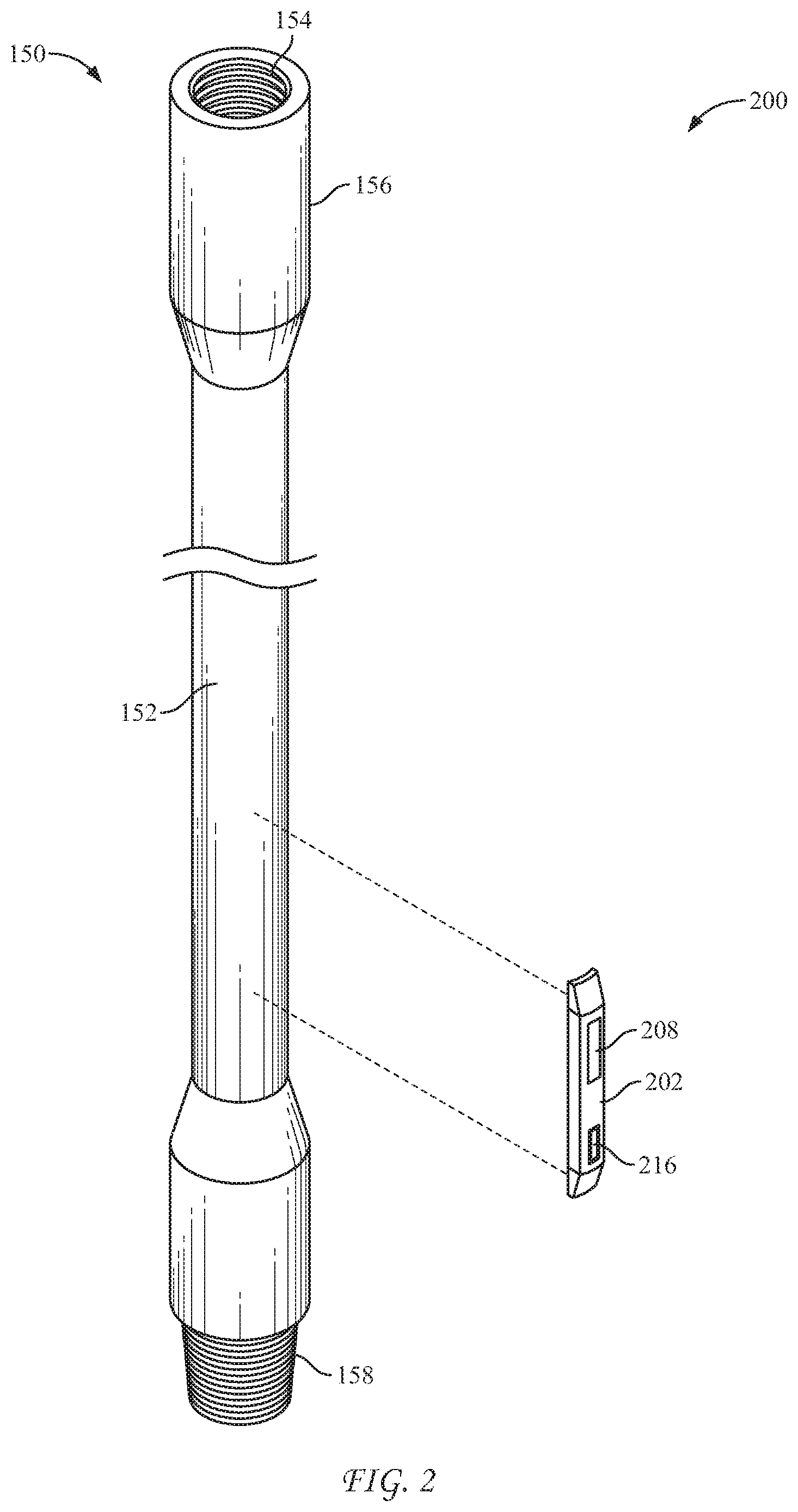
FIG. 2 presents a perspective view of an illustrative tubular section of a real-time system for monitoring plunger properties, in accordance with an embodiment of the disclosure. An intermediate communications node in accordance herewith, is shown in exploded form away from the tubular section.
FIG. 3 presents a cross-sectional view of the intermediate communications node of FIG. 2. The view is taken along the longitudinal axis of the intermediate communications node.
FIG. 4 is a cross-sectional view of an illustrative embodiment of a sensor communications node having a sensor positioned within the sensor communications node. The view is taken along the longitudinal axis of the sensor communications node.
FIG. 5 is another cross-sectional view of an illustrative embodiment of a sensor communications node having a sensor positioned along the wellbore external to the sensor communications node. The view is again taken along the longitudinal axis of the sensor communications node.
FIG. 6 is a flowchart of an exemplary method of monitoring plunger properties and controlling plunger performance in a gas producing well, in accordance with an embodiment of the disclosure.
DETAILED DESCRIPTION
Terminology
The words and phrases used herein should be understood and interpreted to have a meaning consistent with the understanding of those words and phrases by those skilled in the relevant art. No special definition of a term or phrase, i.e., a definition that is different from the ordinary and customary meaning as understood by those skilled in the art, is intended to be implied by consistent usage of the term or phrase herein. To the extent that a term or phrase is intended to have a special meaning, i.e., a meaning other than the broadest meaning understood by skilled artisans, such a special or clarifying definition will be expressly set forth in the specification in a definitional manner that provides the special or clarifying definition for the term or phrase.
For example, the following discussion contains a non-exhaustive list of definitions of several specific terms used in this disclosure (other terms may be defined or clarified in a definitional manner elsewhere herein). These definitions are intended to clarify the meanings of the terms used herein. It is believed that the terms are used in a manner consistent with their ordinary meaning, but the definitions are nonetheless specified here for clarity.
A/an: The articles "a" and "an" as used herein mean one or more when applied to any feature in embodiments and implementations of the present invention described in the specification and claims. The use of "a" and "an" does not limit the meaning to a single feature unless such a limit is specifically stated. The term "a" or "an" entity refers to one or more of that entity. As such, the terms "a" (or "an"), "one or more" and "at least one" can be used interchangeably herein.
About: As used herein, "about" refers to a degree of deviation based on experimental error typical for the particular property identified. The latitude provided the term "about" will depend on the specific context and particular property and can be readily discerned by those skilled in the art. The term "about" is not intended to either expand or limit the degree of equivalents which may otherwise be afforded a particular value. Further, unless otherwise stated, the term "about" shall expressly include "exactly," consistent with the discussion below regarding ranges and numerical data.
Above/below: In the following description of the representative embodiments of the invention, directional terms, such as "above", "below", "upper", "lower", etc., are used for convenience in referring to the accompanying drawings. In general, "above", "upper", "upward" and similar terms refer to a direction toward the earth's surface along a wellbore, and "below", "lower", "downward" and similar terms refer to a direction away from the earth's surface along the wellbore. Continuing with the example of relative directions in a wellbore, "upper" and "lower" may also refer to relative positions along the longitudinal dimension of a wellbore rather than relative to the surface, such as in describing both vertical and horizontal wells.
And/or: The term "and/or" placed between a first entity and a second entity means one of (1) the first entity, (2) the second entity, and (3) the first entity and the second entity. Multiple elements listed with "and/or" should be construed in the same fashion, i.e., "one or more" of the elements so conjoined. Other elements may optionally be present other than the elements specifically identified by the "and/or" clause, whether related or unrelated to those elements specifically identified. Thus, as a non-limiting example, a reference to "A and/or B", when used in conjunction with open-ended language such as "comprising" can refer, in one embodiment, to A only (optionally including elements other than B); in another embodiment, to B only (optionally including elements other than A); in yet another embodiment, to both A and B (optionally including other elements). As used herein in the specification and in the claims, "or" should be understood to have the same meaning as "and/or" as defined above. For example, when separating items in a list, "or" or "and/or" shall be interpreted as being inclusive, i.e., the inclusion of at least one, but also including more than one, of a number or list of elements, and, optionally, additional unlisted items. Only terms clearly indicated to the contrary, such as "only one of" or "exactly one of," or, when used in the claims, "consisting of," will refer to the inclusion of exactly one element of a number or list of elements. In general, the term "or" as used herein shall only be interpreted as indicating exclusive alternatives (i.e., "one or the other but not both") when preceded by terms of exclusivity, such as "either," "one of," "only one of," or "exactly one of".
Any: The adjective "any" means one, some, or all indiscriminately of whatever quantity.
At least: As used herein in the specification and in the claims, the phrase "at least one," in reference to a list of one or more elements, should be understood to mean at least one element selected from any one or more of the elements in the list of elements, but not necessarily including at least one of each and every element specifically listed within the list of elements and not excluding any combinations of elements in the list of elements. This definition also allows that elements may optionally be present other than the elements specifically identified within the list of elements to which the phrase "at least one" refers, whether related or unrelated to those elements specifically identified. Thus, as a non-limiting example, "at least one of A and B" (or, equivalently, "at least one of A or B," or, equivalently "at least one of A and/or B") can refer, in one embodiment, to at least one, optionally including more than one, A, with no B present (and optionally including elements other than B); in another embodiment, to at least one, optionally including more than one, B, with no A present (and optionally including elements other than A); in yet another embodiment, to at least one, optionally including more than one, A, and at least one, optionally including more than one, B (and optionally including other elements). The phrases "at least one", "one or more", and "and/or" are open-ended expressions that are both conjunctive and disjunctive in operation. For example, each of the expressions "at least one of A, B and C", "at least one of A, B, or C", "one or more of A, B, and C", "one or more of A, B, or C" and "A, B, and/or C" means A alone, B alone, C alone, A and B together, A and C together, B and C together, or A, B and C together.
Based on: "Based on" does not mean "based only on", unless expressly specified otherwise. In other words, the phrase "based on" describes both "based only on," "based at least on," and "based at least in part on."
Comprising: In the claims, as well as in the specification, all transitional phrases such as "comprising," "including," "carrying," "having," "containing," "involving," "holding," "composed of," and the like are to be understood to be open-ended, i.e., to mean including but not limited to. Only the transitional phrases "consisting of" and "consisting essentially of" shall be closed or semi-closed transitional phrases, respectively, as set forth in the United States Patent Office Manual of Patent Examining Procedures, Section 2111.03.
Couple: Any use of any form of the terms "connect", "engage", "couple", "attach", or any other term describing an interaction between elements is not meant to limit the interaction to direct interaction between the elements and may also include indirect interaction between the elements described.
Determining: "Determining" encompasses a wide variety of actions and therefore "determining" can include calculating, computing, processing, deriving, investigating, looking up (e.g., looking up in a table, a database or another data structure), ascertaining and the like. Also, "determining" can include receiving (e.g., receiving information), accessing (e.g., accessing data in a memory) and the like. Also, "determining" can include resolving, selecting, choosing, establishing and the like.
Embodiments: Reference throughout the specification to "one embodiment," "an embodiment," "some embodiments," "one aspect," "an aspect," "some aspects," "some implementations," "one implementation," "an implementation," or similar construction means that a particular component, feature, structure, method, or characteristic described in connection with the embodiment, aspect, or implementation is included in at least one embodiment and/or implementation of the claimed subject matter. Thus, the appearance of the phrases "in one embodiment" or "in an embodiment" or "in some embodiments" (or "aspects" or "implementations") in various places throughout the specification are not necessarily all referring to the same embodiment and/or implementation. Furthermore, the particular features, structures, methods, or characteristics may be combined in any suitable manner in one or more embodiments or implementations.
Exemplary: "Exemplary" is used exclusively herein to mean "serving as an example, instance, or illustration." Any embodiment described herein as "exemplary" is not necessarily to be construed as preferred or advantageous over other embodiments.
Flow diagram: Exemplary methods may be better appreciated with reference to flow diagrams or flow charts. While for purposes of simplicity of explanation, the illustrated methods are shown and described as a series of blocks, it is to be appreciated that the methods are not limited by the order of the blocks, as in different embodiments some blocks may occur in different orders and/or concurrently with other blocks from that shown and described. Moreover, less than all the illustrated blocks may be required to implement an exemplary method. In some examples, blocks may be combined, may be separated into multiple components, may employ additional blocks, and so on. In some examples, blocks may be implemented in logic. In other examples, processing blocks may represent functions and/or actions performed by functionally equivalent circuits (e.g., an analog circuit, a digital signal processor circuit, an application specific integrated circuit (ASIC)), or other logic device. Blocks may represent executable instructions that cause a computer, processor, and/or logic device to respond, to perform an action(s), to change states, and/or to make decisions. While the figures illustrate various actions occurring in serial, it is to be appreciated that in some examples various actions could occur concurrently, substantially in parallel, and/or at substantially different points in time. In some examples, methods may be implemented as processor executable instructions. Thus, a machine-readable medium may store processor executable instructions that if executed by a machine (e.g., processor) cause the machine to perform a method.
Full-physics: As used herein, the term "full-physics," "full physics computational simulation," or "full physics simulation" refers to a mathematical algorithm based on first principles that impact the pertinent response of the simulated system.
May: Note that the word "may" is used throughout this application in a permissive sense (i.e., having the potential to, being able to), not a mandatory sense (i.e., must).
Operatively connected and/or coupled: Operatively connected and/or coupled means directly or indirectly connected for transmitting or conducting information, force, energy, or matter.
Optimizing: The terms "optimal," "optimizing," "optimize," "optimality," "optimization" (as well as derivatives and other forms of those terms and linguistically related words and phrases), as used herein, are not intended to be limiting in the sense of requiring the present invention to find the best solution or to make the best decision. Although a mathematically optimal solution may in fact arrive at the best of all mathematically available possibilities, real-world embodiments of optimization routines, methods, models, and processes may work towards such a goal without ever actually achieving perfection. Accordingly, one of ordinary skill in the art having benefit of the present disclosure will appreciate that these terms, in the context of the scope of the present invention, are more general. The terms may describe one or more of: 1) working towards a solution which may be the best available solution, a preferred solution, or a solution that offers a specific benefit within a range of constraints; 2) continually improving; 3) refining; 4) searching for a high point or a maximum for an objective; 5) processing to reduce a penalty function; 6) seeking to maximize one or more factors in light of competing and/or cooperative interests in maximizing, minimizing, or otherwise controlling one or more other factors, etc.
Order of steps: It should also be understood that, unless clearly indicated to the contrary, in any methods claimed herein that include more than one step or act, the order of the steps or acts of the method is not necessarily limited to the order in which the steps or acts of the method are recited.
Ranges: Concentrations, dimensions, amounts, and other numerical data may be presented herein in a range format. It is to be understood that such range format is used merely for convenience and brevity and should be interpreted flexibly to include not only the numerical values explicitly recited as the limits of the range, but also to include all the individual numerical values or sub-ranges encompassed within that range as if each numerical value and sub-range is explicitly recited. For example, a range of about 1 to about 200 should be interpreted to include not only the explicitly recited limits of 1 and about 200, but also to include individual sizes such as 2, 3, 4, etc. and sub-ranges such as 10 to 50, 20 to 100, etc. Similarly, it should be understood that when numerical ranges are provided, such ranges are to be construed as providing literal support for claim limitations that only recite the lower value of the range as well as claims limitation that only recite the upper value of the range. For example, a disclosed numerical range of 10 to 100 provides literal support for a claim reciting "greater than 10" (with no upper bounds) and a claim reciting "less than 100" (with no lower bounds).
Description
Specific forms will now be described further by way of example. While the following examples demonstrate certain forms of the subject matter disclosed herein, they are not to be interpreted as limiting the scope thereof, but rather as contributing to a complete description.
Referring now to FIG. 1, a schematic cross-sectional view of illustrative, non-exclusive examples of a gas producing well 20 that may include and/or utilize a real-time system for monitoring plunger properties in a gas producing well 100, according to the present disclosure. Gas producing well 20 also may be referred to herein as a hydrocarbon well 20 and/or simply as a well 20. Well 20 includes a wellbore 30 that extends between a surface region 22 and a subterranean formation 26 that is present within a subsurface region 24. Well 20 further includes a tubular body 34 that defines a wellbore conduit 36. The wellbore conduit 36 extends within the wellbore 30, is defined within the wellbore 30, and/or includes at least a portion of the wellbore 30.
A plunger 50 is positionable within a target region 38 of wellbore conduit 36. Target region 38 of wellbore conduit 36 may include and/or be any suitable portion of the wellbore conduit that is located downhole from a surface tree 27, that is located and/or defined within subsurface region 24, that is located and/or defined within subterranean formation 26, and/or in which liquid 44 collects. As illustrative, non-exclusive examples, target region 38 may include, be located within, and/or be defined within a portion of subsurface region 24 that provides the wellbore fluid stream to the wellbore conduit and/or within a portion of the wellbore conduit that is distal from an uphole end of the wellbore conduit.
As another illustrative, non-exclusive example, target region 38 may be at least a threshold distance from surface region 22 along a length of wellbore 30. Illustrative, non-exclusive examples of the threshold distance include threshold distances of at least 100 meters (m), at least 250 m, at least 500 m, at least 750 m, at least 1,000 m, at least 1,250 m, at least 1,500 m, at least 2,000 m, at least 3,000 m, at least 4,000 m, at least 5,000 m, at least 7,500 m, or at least 10,000 m.
Plunger 50 may be configured to rest, reside, remain and/or be located within target region 38 of wellbore conduit 36. The plunger 50 may be conveyed within wellbore conduit 36 in uphole direction 80, as illustrated in dashed lines in FIG. 1, by and/or with wellbore fluid stream 42. This enables plunger 50 to urge and/or convey a liquid 44 and/or a solid material 46, which may be present within wellbore conduit 36, in the uphole direction. This conveying may thereby permit removal of the liquid 44 and/or the solid material 46 from the wellbore conduit and/or decrease a resistance to the flow of wellbore fluid stream 42 from the subterranean formation, within the wellbore conduit, in the uphole direction, and/or from the gaseous hydrocarbon well 20.
Subsequent to being conveyed in uphole direction 80, plunger 50 may be stored within a plunger lubricator 32 of tree 27. When conditions dictate, the well 20 may be shut in and plunger 50 permitted to fall, such as under the influence of gravity, in a downhole direction 82 and/or toward target region 38 within wellbore conduit 36. The plunger 50 then may rest, reside, remain and/or be located within the target region 38 of the wellbore conduit 36, such as for at least a period of time, before once again being conveyed in uphole direction 80 by wellbore fluid stream 42. This process may be repeated any suitable number of times and/or with any suitable frequency to remove liquid 44 and/or solid material 46 from the wellbore conduit 36.
Wellbore conduit 36 may be defined by any suitable structure and/or tubular body 34. As an illustrative, non-exclusive example, wellbore conduit 36 may be defined by tubular body 34. As another illustrative, non-exclusive example, wellbore conduit 36 may be defined by (or tubular body 34 may be) a casing string that extends within wellbore 30. As yet another illustrative, non-exclusive example, wellbore conduit 36 may be defined by (or tubular body 34 may be) a tubing or production string that extends within wellbore 30.
As illustrated in solid lines in FIG. 1, wellbore 30 may include and/or be a vertical, or at least substantially vertical, wellbore 30 (or wellbore conduit 36 may include and/or be a vertical, or at least substantially vertical, wellbore conduit 36). However, and as illustrated in dash-dot lines in FIG. 1, wellbore 30 (or wellbore conduit 36) also may include and/or define one or more horizontal and/or deviated regions. As further illustrated in FIG. 1, target region 38 may be located in any suitable portion of wellbore conduit 36, including a vertical portion, a deviated portion, and/or a horizontal portion of the wellbore conduit. Target region 38 may located within a deviated and/or horizontal portion of wellbore conduit 36 and plunger 50 may be conveyed in downhole direction 82 thereto.
As may be appreciated, target region 38 of wellbore conduit 36 may include and/or be any suitable portion of the wellbore conduit that is located downhole from surface tree 27, that is located and/or defined within subsurface region 24, that is located and/or defined within subterranean formation 26, and/or in which liquid 44 collects. As illustrative, non-exclusive examples, target region 38 may include, be located within, and/or be defined within a portion of subsurface region 24 that provides the wellbore fluid stream to the wellbore conduit and/or within a portion of the wellbore conduit that is distal from an uphole end of the wellbore conduit. As another illustrative, non-exclusive example, target region 38 may be at least a threshold distance from surface region 22 along a length of wellbore 30. Illustrative, non-exclusive examples of the threshold distance include threshold distances of at least 100 meters (m), at least 250 m, at least 500 m, at least 750 m, at least 1,000 m, at least 1,250 m, at least 1,500 m, at least 2,000 m, at least 3,000 m, at least 4,000 m, at least 5,000 m, at least 7,500 m, or at least 10,000 m.
As illustrated in FIG. 1, well 20 further may include a downhole support structure 97. Downhole support structure 97 may be configured to support, locate, and/or retain plunger 50 when the plunger is located within target region 38 of wellbore conduit 36. Should plunger 50 be provided with downhole electronics, plunger 50 may include a power source 94, such as a battery. Under these conditions, downhole support structure 97 may include a downhole electrical connection 98 that is configured to provide an electric current to power source 94, such as to charge the power source. Plunger 50 may also include a detector 92 that is configured to detect variables that may be representative of conditions proximal to plunger 50 within wellbore conduit 36.
Well 20 also may include an uphole support structure 28. Uphole support structure 28 which may be associated with, near, and/or proximal to an uphole end of wellbore 36, may be associated with, near, and/or proximal to a surface tree 27 that is associated with well 20 and/or that is configured to selectively regulate flow of wellbore fluid stream 42 from well 20. As a further example, uphole support structure 28 may be located within a lubricator 32 of surface tree 27. Similar to downhole support structure 97, uphole support structure 28 may include an uphole electrical connection 29, which may be at least substantially similar to downhole electrical connection 98. When plunger 50 is conveyed in uphole direction 80, near surface region 22, into surface tree 27, and/or into contact with uphole support structure 28, the plunger may be retained on uphole support structure 28 to permit charging of power source 94.
Wellbore fluid stream 42 may include any wellbore fluid 40 that may flow from subterranean formation 26, may flow through wellbore conduit 36, and/or may be produced from gaseous hydrocarbon well 20. Generally, wellbore fluid stream 42 will include and/or be a gaseous stream and/or a vaporous stream, and illustrative, non-exclusive examples of wellbore fluid stream 42 include a gaseous hydrocarbon stream, a vaporous hydrocarbon stream, a methane stream, and/or a natural gas stream.
Liquid 44 may include any liquid that may accumulate within wellbore conduit 36, may be present within wellbore conduit 36, and/or may (at least partially) restrict flow of wellbore fluid stream 42 within wellbore conduit 36. Illustrative, non-exclusive examples of liquid 44 include water and/or a liquid hydrocarbon. Solid material 46 may include any solid, solid-like, and/or gel material that may accumulate within wellbore conduit 36, may be present within wellbore conduit 36, and/or may (at least partially) restrict flow of wellbore fluid stream 42 within wellbore conduit 36. Illustrative, non-exclusive examples of solid material 46 include a paraffin, a wax, and/or scale. Liquid 44 and/or solid material 46 present in wellbore conduit 36 generally may be referred to herein as wellbore material 48.
As used herein, uphole direction 80 may include any direction that is along (or parallel to) a respective length (or portion) of wellbore conduit 36 and that is directed toward, or closer to, an intersection of the wellbore conduit with surface region 22 and/or toward surface tree 27, when present. Additionally or alternatively, moving an object in the uphole direction also may be described as moving the object in a direction along a trajectory of wellbore conduit 36 that tends to decrease a distance between the object and a surface terminal end 37 of wellbore conduit 36.
Conversely, downhole direction 82 may include any direction that is along (or parallel to) the respective length (or portion) of wellbore conduit 36 and that tends to move away from the intersection of the wellbore with surface region 22, away from surface tree 27, away from surface terminal end 37, toward a subterranean terminal end 39 of wellbore conduit 36, and/or toward a toe 41 (when present) of wellbore conduit 36.
Surface tree 27 may include and/or be any suitable structure that may be configured to control and/or regulate at least a portion of the fluid flows into and/or out of well 20. As illustrative, non-exclusive examples, surface tree 27 may include one or more valves, spools, and/or fittings. Surface tree 27 also may be referred to herein as a Christmas tree 27, a surface valve assembly 27, and/or as a surface flow control assembly 27.
Still, referring to FIG. 1, the real-time system for monitoring plunger properties in a gas producing well 100 includes the plunger 50, plunger 50 including a substantially cylindrical body 56; at least one sensor 102 disposed along a tubular body 34; and at least one sensor communications node 104 placed along the tubular body 34 and affixed to a wall 62 of the tubular body 34. The at least one sensor communications node 104 may be operatively connected, structured and arranged or otherwise in electrical communication with the at least one sensor 102 and configured to receive signals therefrom. In some embodiments, the at least one sensor 102 may be positioned on a surface of, or within, the at least one sensor communications node 104.
In some embodiments, the at least one sensor 102 is selected from a plunger position sensor, a plunger wear sensor, plunger velocity sensor, a fluid density sensor, a fluid resistivity sensor, a fluid velocity sensor, a pressure drop sensor or a combination thereof. In some embodiments, the at least one sensor 102 comprises a plurality of sensors 102. In some embodiments, the at least one sensor 102 employs passive acoustic monitoring, electromagnetic signature detection, sonar monitoring, radar monitoring, or radiation monitoring to detect the properties of plunger 50.
The sensor nodes could employ passive acoustic monitoring, electromagnetic signature detection, sonar, radar, radiation sources, and/or other means to detect the properties described above. The data transmitted to surface could be incorporated into the plunger lift control system for richer data collection, exception-based surveillance, autonomous optimization, etc.
The real-time system for monitoring plunger properties in a gas producing well 100 may also include a topside communications node 106 placed proximate a surface or surface region 22. In some embodiments, the topside communications node 106 is configured to receive and/or transmit acoustic signals. The topside communications node 102 can be below grade as shown in FIG. 1, or above grade.
The real-time system for monitoring plunger properties in a gas producing well 100 may also include a plurality of intermediate communications nodes 108 spaced along the tubular body 34 and attached to a wall 62 of the tubular body 34. The intermediate communications nodes 108 are configured to transmit signals received from the at least one sensor communications node 104 to the topside communications node 106 in substantially a node-to-node arrangement.
In some embodiments, one or more of the intermediate communications nodes 108 may be positioned between an at least one sensor communications node 104 and the topside communications node 106. In some embodiments, the intermediate communications nodes 108 are configured to receive and then relay acoustic signals along the length of the wellbore 30. In some embodiments, the intermediate communications nodes 108 utilize separate electro-acoustic transducers to receive and relay mechanical waves. In some embodiments, the intermediate communications nodes 108 utilize two-way electro-acoustic transducers to both receive and relay mechanical waves.
The real-time system for monitoring plunger properties in a gas producing well 100 may also include a receiver 110, which may be positioned at the surface or surface region 22. The receiver 110 may be configured to receive signals from the topside communications node 106 and a plunger lift control system 90, 90'. In some embodiments, the plunger lift control system 90 may reside or be located at or within plunger 50, and is structured and arranged to communicate with the topside communications node 106. In some embodiments, the plunger lift control system 90' may be positioned at the surface or surface region 22 or may reside or be located at or within receiver 110, and is structured and arranged to communicate with the topside communications node 106. In some embodiments, data transmitted topside is utilized by the plunger lift control system 90, 90' for plunger surveillance and optimization.
The receiver 110 includes a processor 112 that receives signals sent from the topside communications node 106. The signals may be received through a wire (not shown) such as a co-axial cable, a fiber optic cable, a USB cable, or other electrical or optical communications wire. Alternatively, the receiver 110 may receive signals from the topside communications node 106 wirelessly through a modem, a transceiver or other wireless communications link. In some embodiments, the receiver 110 receives electrical signals via a so-called Class I, Division 1 conduit, that is, a housing for wiring that is considered acceptably safe in an explosive environment. In some applications, radio, infrared or microwave signals may be utilized.
In some embodiments, the processor 112 may be incorporated into a computer 114 having a screen 116. The computer 114 may have a separate keyboard 118, as is typical for a desk-top computer, or an integral keyboard as is typical for a laptop or a personal digital assistant. In one aspect, the processor 112 is part of a multi-purpose "smart phone" having specific applications and wireless connectivity.
Data may be sent along the nodes, not only from the at least one sensor 102 up to the receiver 110, but also from the receiver 110 down to the at least one sensor 102. This transmission may be of benefit in the event that the operator wishes to make a change in the operations. This is also of benefit when the at least one sensor 102 is actually another type of device, such as an inflow control device that opens, closes or otherwise actuates in response to a signal from the surface or surface region 22.
As may be appreciated, in FIG. 1, the at least one sensor communications node 104 and the plurality of intermediate communications nodes 108 are shown schematically. Referring now to FIG. 2, an enlarged perspective view of an illustrative tubular section 150 of a tubular body 34, along with an illustrative intermediate communications node 200. The illustrative intermediate communications node 200 is shown exploded away from the tubular section 150. The tubular section 150 has an elongated wall 152 defining an internal bore 154. The tubular section 150 has a box end 156 having internal threads, and a pin end 158 having external threads.
As noted, the illustrative intermediate communications node 200 is shown exploded away from the tubular section 150. The intermediate communications node 200 is structured and arranged to attach to the wall 152 of the tubular section 150 at a selected location. In one aspect, selected tubular sections 150 will each have an intermediate communications node 200 between the box end 156 and the pin end 158. In one arrangement, the intermediate communications node 200 is placed immediately adjacent the box end 156 or, alternatively, immediately adjacent the pin end 158 of every tubular section 150. In another arrangement, the intermediate communications node 200 is placed at a selected location along every second or every third tubular section 150. In other aspects, more or less than one intermediate communications node 200 may be placed per tubular section 150.
In some embodiments, the intermediate communications node 200 shown in FIG. 2 is designed to be pre-welded onto the wall 152 of the tubular section 150. In some embodiments, intermediate communications node 200 is configured to be selectively attachable to/detachable from a intermediate by mechanical means at a well 20. This may be done, for example, through the use of clamps (not shown). Alternatively, an epoxy or other suitable acoustic couplant may be used for chemical bonding. In any instance, the intermediate communications node 200 is an independent wireless communications device that is designed to be attached to an external surface of a tubular.
There are benefits to the use of an externally-placed communications node that uses acoustic waves. For example, such a node will not interfere with the flow of fluids within the internal bore 154 of the tubular section 150. Further, installation and mechanical attachment can be readily assessed or adjusted, as necessary.
As shown in FIG. 2, the intermediate communications node 200 includes a housing 202. The housing 202 supports a power source residing within the housing, which may be one or more batteries, as shown schematically at 208. The housing 202 also supports an electro-acoustic transducer, shown schematically at 216. In some embodiments, the electro-acoustic transducer 216 may be a two-way transceiver that can both receive and transmit acoustic signals. The intermediate communications node 200 is intended to represent the plurality of intermediate communications nodes 108 of FIG. 1, in one embodiment. The two-way electro-acoustic transducer 216 in each intermediate communications node 200 allows acoustic signals to be sent from node-to-node, either up the wellbore 20 or down the wellbore 20. Where the tubular section 150 is formed of carbon steel, such as a casing or liner, the housing 202 is preferably fabricated from carbon steel. This metallurgical match avoids galvanic corrosion at the coupling.
FIG. 3 provides a cross-sectional view of the intermediate communications node 200 of FIG. 2. The view is taken along the longitudinal axis of the intermediate communications node 200. The housing 202 is dimensioned to be strong enough to protect internal electronics. In one aspect, the housing 202 has an outer wall 204 that may be about 0.2 inches (0.51 cm) in thickness. A cavity 206 houses the electronics, including, by way of example and not of limitation, a battery 208, a power supply wire 210, a transceiver 212, and a circuit board 214. The circuit board 214 will preferably include a micro-processor or electronics module that processes acoustic signals. An electro-acoustic transducer 216 is provided to convert acoustical energy to electrical energy (or vice-versa) and is coupled with outer wall 204 on the side attached to the tubular body.
FIG. 4 provides a cross-sectional view of a sensor communications node 300. The sensor communications node 300 is intended to represent the plurality of sensor communications nodes 104 of FIG. 1, in one embodiment. The view is taken along the longitudinal axis of the sensor communications node 300. The sensor communications node 300 includes a housing 302. As with the housing 202 of intermediate communications node 200, the housing 302 is structured and arranged to be attached to an outer wall of a tubular section, such as the tubular section 150 of FIG. 2. Where the tubular section is formed of a carbon steel, such as a casing or liner, the housing 302 is preferably fabricated from carbon steel. This metallurgical match avoids galvanic corrosion at the coupling.
The housing 302 is dimensioned to be strong enough to protect internal electronics. In one aspect, the housing 302 has an outer wall 304 that may be about 0.2 inches (0.51 cm) in thickness. A cavity 306 houses the electronics, including, by way of example and not of limitation, a battery 308, a power supply wire 310, a transceiver 312, and a circuit board 314. The circuit board 314 will preferably include a micro-processor or electronics module that processes acoustic signals. An electro-acoustic transducer 316 is provided to convert acoustical energy to electrical energy (or vice-versa) and is coupled with outer wall 304 on the side attached to the tubular body. The transducer 316 is in electrical communication with at least one sensor 318, which may be the at least one sensor 102 of FIG. 1, in one embodiment.
It is noted that in FIG. 4, the at least one sensor 318 resides within the housing 302 of the sensor communications node 300. Referring now to FIG. 5, an alternate embodiment is presented wherein an at least one sensor 418 is shown to reside external to a sensor communications node 400, such as above or below the sensor communications node 400 along the wellbore. In FIG. 5, the sensor communications node 400 is also intended to represent the plurality of sensor communications nodes 104 of FIG. 1, in one embodiment. The sensor communications node 400 includes a housing 402, which is structured and arranged to be attached to an outer wall of a tubular section, such as the tubular section 150 of FIG. 2.
In one aspect, the housing 402 has an outer wall 404 that may be about 0.2 inches (0.51 cm) in thickness. A cavity 406 houses the electronics, including, by way of example and not of limitation, a battery 408, a power supply wire 410, a transceiver 412, and a circuit board 414. The circuit board 414 will preferably include a micro-processor or electronics module that processes acoustic signals. An electro-acoustic transducer 416 is provided to convert acoustical energy to electrical energy (or vice-versa) and is coupled with outer wall 404 on the side attached to the tubular body. The transducer 416 is in electrical communication w
References
D00000
D00001
D00002
D00003
D00004
XML
uspto.report is an independent third-party trademark research tool that is not affiliated, endorsed, or sponsored by the United States Patent and Trademark Office (USPTO) or any other governmental organization. The information provided by uspto.report is based on publicly available data at the time of writing and is intended for informational purposes only.
While we strive to provide accurate and up-to-date information, we do not guarantee the accuracy, completeness, reliability, or suitability of the information displayed on this site. The use of this site is at your own risk. Any reliance you place on such information is therefore strictly at your own risk.
All official trademark data, including owner information, should be verified by visiting the official USPTO website at www.uspto.gov. This site is not intended to replace professional legal advice and should not be used as a substitute for consulting with a legal professional who is knowledgeable about trademark law.