Method and system for performing operations using communications for a hydrocarbon system
Song , et al.
U.S. patent number 10,690,794 [Application Number 16/175,441] was granted by the patent office on 2020-06-23 for method and system for performing operations using communications for a hydrocarbon system. This patent grant is currently assigned to ExxonMobil Upstream Research Company. The grantee listed for this patent is Scott W. Clawson, Mark M. Disko, Limin Song, Badrinarayanan Velamur Asokan, Xiaohua Yi, Yibing Zhang. Invention is credited to Scott W. Clawson, Mark M. Disko, Limin Song, Badrinarayanan Velamur Asokan, Xiaohua Yi, Yibing Zhang.


| United States Patent | 10,690,794 |
| Song , et al. | June 23, 2020 |
Method and system for performing operations using communications for a hydrocarbon system
Abstract
A method and system are described for communicating within a system, which may be along tubular members. The method includes constructing a communication network for a hydrocarbon system, which includes one or more wellbores accessing a subsurface region or a pipeline, and using the communication network in hydrocarbon operations, such as hydrocarbon exploration, hydrocarbon development, and/or hydrocarbon production.
| Inventors: | Song; Limin (West Windsor, NJ), Zhang; Yibing (Annandale, NJ), Disko; Mark M. (Glen Gardner, NJ), Clawson; Scott W. (Califon, NJ), Velamur Asokan; Badrinarayanan (Houston, TX), Yi; Xiaohua (Houston, TX) | ||||||||||
|---|---|---|---|---|---|---|---|---|---|---|---|
| Applicant: |
|
||||||||||
| Assignee: | ExxonMobil Upstream Research
Company (Spring, TX) |
||||||||||
| Family ID: | 66532304 | ||||||||||
| Appl. No.: | 16/175,441 | ||||||||||
| Filed: | October 30, 2018 |
Prior Publication Data
| Document Identifier | Publication Date | |
|---|---|---|
| US 20190154859 A1 | May 23, 2019 | |
Related U.S. Patent Documents
| Application Number | Filing Date | Patent Number | Issue Date | ||
|---|---|---|---|---|---|
| 62588067 | Nov 17, 2017 | ||||
| Current U.S. Class: | 1/1 |
| Current CPC Class: | G01V 1/46 (20130101); E21B 47/14 (20130101); G01V 11/002 (20130101); E21B 47/16 (20130101); E21B 47/017 (20200501); E21B 47/13 (20200501); G01V 1/247 (20130101) |
| Current International Class: | G01V 1/46 (20060101); E21B 47/01 (20120101); E21B 47/14 (20060101); E21B 47/16 (20060101); E21B 47/12 (20120101); G01V 11/00 (20060101); G01V 1/24 (20060101) |
References Cited [Referenced By]
U.S. Patent Documents
| 3103643 | September 1963 | Kalbfell |
| 3205477 | September 1965 | Kalbfell |
| 3512407 | May 1970 | Zill |
| 3637010 | January 1972 | Malay et al. |
| 3741301 | June 1973 | Malay et al. |
| 3781783 | December 1973 | Tucker |
| 3790930 | February 1974 | Lamel et al. |
| 3900827 | August 1975 | Lamel et al. |
| 3906434 | September 1975 | Lamel et al. |
| 4001773 | January 1977 | Lamel et al. |
| 4283780 | August 1981 | Nardi |
| 4298970 | November 1981 | Shawhan et al. |
| 4302826 | November 1981 | Kent et al. |
| 4314365 | February 1982 | Peterson et al. |
| 4884071 | November 1989 | Howard |
| 4962489 | October 1990 | Medlin et al. |
| 5128901 | July 1992 | Drumheller |
| 5136613 | August 1992 | Dumestre, III |
| 5166908 | November 1992 | Montgomery |
| 5182946 | February 1993 | Boughner et al. |
| 5234055 | August 1993 | Cornette |
| 5283768 | February 1994 | Rorden |
| 5373481 | December 1994 | Orban et al. |
| 5468025 | November 1995 | Adinolfe et al. |
| 5480201 | January 1996 | Mercer |
| 5495230 | February 1996 | Lian |
| 5562240 | October 1996 | Campbell |
| 5592438 | January 1997 | Rorden et al. |
| 5667650 | September 1997 | Face et al. |
| 5850369 | December 1998 | Rorden et al. |
| 5857146 | January 1999 | Kido |
| 5924499 | July 1999 | Birchak et al. |
| 5960883 | October 1999 | Tubel et al. |
| 5995449 | November 1999 | Green et al. |
| 6049508 | April 2000 | Deflandre |
| 6125080 | September 2000 | Sonnenschein et al. |
| 6128250 | October 2000 | Reid et al. |
| 6177882 | January 2001 | Ringgenberg et al. |
| 6236850 | May 2001 | Desai |
| 6239690 | May 2001 | Burbidge et al. |
| 6300743 | October 2001 | Patino et al. |
| 6320820 | November 2001 | Gardner et al. |
| 6324904 | December 2001 | Ishikawa et al. |
| 6360769 | March 2002 | Brisco |
| 6394184 | May 2002 | Tolman et al. |
| 6400646 | June 2002 | Shah et al. |
| 6429784 | August 2002 | Beique et al. |
| 6462672 | October 2002 | Besson |
| 6543538 | April 2003 | Tolman et al. |
| 6670880 | December 2003 | Hall et al. |
| 6679332 | January 2004 | Vinegar et al. |
| 6695277 | February 2004 | Gallis |
| 6702019 | March 2004 | Dusterhoft et al. |
| 6717501 | April 2004 | Hall et al. |
| 6727827 | April 2004 | Edwards et al. |
| 6772837 | August 2004 | Dusterhoft et al. |
| 6816082 | November 2004 | Laborde |
| 6868037 | March 2005 | Dasgupta et al. |
| 6880634 | April 2005 | Gardner et al. |
| 6883608 | April 2005 | Parlar et al. |
| 6899178 | May 2005 | Tubel |
| 6909667 | June 2005 | Shah et al. |
| 6912177 | June 2005 | Smith |
| 6920085 | July 2005 | Finke et al. |
| 6930616 | August 2005 | Tang et al. |
| 6940392 | September 2005 | Chan et al. |
| 6940420 | September 2005 | Jenkins |
| 6953094 | October 2005 | Ross et al. |
| 6956791 | October 2005 | Dopf et al. |
| 6980929 | December 2005 | Aronstam et al. |
| 6987463 | January 2006 | Beique et al. |
| 7006918 | February 2006 | Economides et al. |
| 7011157 | March 2006 | Costley et al. |
| 7036601 | May 2006 | Berg et al. |
| 7051812 | May 2006 | McKee et al. |
| 7064676 | June 2006 | Hall et al. |
| 7082993 | August 2006 | Ayoub et al. |
| 7090020 | August 2006 | Hill et al. |
| 7140434 | November 2006 | Chouzenoux et al. |
| 7219762 | May 2007 | James et al. |
| 7224288 | May 2007 | Hall et al. |
| 7228902 | June 2007 | Oppelt |
| 7249636 | July 2007 | Ohmer |
| 7252152 | August 2007 | LoGiudice et al. |
| 7257050 | August 2007 | Stewart et al. |
| 7261154 | August 2007 | Hall et al. |
| 7261162 | August 2007 | Deans et al. |
| 7275597 | October 2007 | Hall et al. |
| 7277026 | October 2007 | Hall et al. |
| RE40032 | January 2008 | van Bokhorst et al. |
| 7317990 | January 2008 | Sinha et al. |
| 7321788 | January 2008 | Addy et al. |
| 7322416 | January 2008 | Burris, II et al. |
| 7325605 | February 2008 | Fripp et al. |
| 7339494 | March 2008 | Shah et al. |
| 7348893 | March 2008 | Huang et al. |
| 7385523 | June 2008 | Thomeer et al. |
| 7387165 | June 2008 | Lopez de Cardenas et al. |
| 7411517 | August 2008 | Flanagan |
| 7477160 | January 2009 | Lemenager et al. |
| 7516792 | April 2009 | Lonnes et al. |
| 7551057 | June 2009 | King et al. |
| 7590029 | September 2009 | Tingley |
| 7595737 | September 2009 | Fink et al. |
| 7602668 | October 2009 | Liang et al. |
| 7649473 | January 2010 | Johnson et al. |
| 7750808 | July 2010 | Masino et al. |
| 7775279 | August 2010 | Marya et al. |
| 7787327 | August 2010 | Tang et al. |
| 7819188 | October 2010 | Auzerais et al. |
| 7828079 | November 2010 | Oothoudt |
| 7831283 | November 2010 | Ogushi et al. |
| 7913773 | March 2011 | Li et al. |
| 7952487 | May 2011 | Montebovi |
| 7994932 | August 2011 | Huang et al. |
| 8004421 | August 2011 | Clark |
| 8044821 | October 2011 | Mehta |
| 8049506 | November 2011 | Lazarev |
| 8115651 | February 2012 | Camwell et al. |
| 8117907 | February 2012 | Han et al. |
| 8157008 | April 2012 | Lilley |
| 8162050 | April 2012 | Roddy et al. |
| 8220542 | July 2012 | Whitsitt et al. |
| 8237585 | August 2012 | Zimmerman |
| 8242928 | August 2012 | Prammer |
| 8276674 | October 2012 | Lopez de Cardenas et al. |
| 8284075 | October 2012 | Fincher et al. |
| 8284947 | October 2012 | Giesbrecht et al. |
| 8316936 | November 2012 | Roddy et al. |
| 8330617 | December 2012 | Chen et al. |
| 8347982 | January 2013 | Hannegan et al. |
| 8358220 | January 2013 | Savage |
| 8376065 | February 2013 | Teodorescu et al. |
| 8381822 | February 2013 | Hales et al. |
| 8388899 | March 2013 | Mitani et al. |
| 8411530 | April 2013 | Slocum et al. |
| 8434354 | May 2013 | Crow et al. |
| 8494070 | July 2013 | Luo et al. |
| 8496055 | July 2013 | Mootoo et al. |
| 8539890 | September 2013 | Tripp et al. |
| 8544564 | October 2013 | Moore et al. |
| 8552597 | October 2013 | Song et al. |
| 8556302 | October 2013 | Dole |
| 8559272 | October 2013 | Wang |
| 8596359 | December 2013 | Grigsby et al. |
| 8605548 | December 2013 | Froelich |
| 8607864 | December 2013 | Mcleod et al. |
| 8664958 | March 2014 | Simon |
| 8672875 | March 2014 | Vanderveen et al. |
| 8675779 | March 2014 | Zeppetelle et al. |
| 8683859 | April 2014 | Godager |
| 8689621 | April 2014 | Godager |
| 8701480 | April 2014 | Eriksen |
| 8750789 | June 2014 | Baldemair et al. |
| 8787840 | July 2014 | Srinivasan et al. |
| 8805632 | August 2014 | Coman et al. |
| 8826980 | September 2014 | Neer |
| 8833469 | September 2014 | Purkis |
| 8893784 | November 2014 | Abad |
| 8910716 | December 2014 | Newton et al. |
| 8994550 | March 2015 | Millot et al. |
| 8995837 | March 2015 | Mizuguchi et al. |
| 9062508 | June 2015 | Huval et al. |
| 9062531 | June 2015 | Jones |
| 9075155 | July 2015 | Luscombe et al. |
| 9078055 | July 2015 | Nguyen et al. |
| 9091153 | July 2015 | Yang et al. |
| 9133705 | September 2015 | Angeles Boza |
| 9140097 | September 2015 | Themig et al. |
| 9144894 | September 2015 | Barnett et al. |
| 9206645 | December 2015 | Hallundbaek |
| 9279301 | March 2016 | Lovorn et al. |
| 9284819 | March 2016 | Tolman et al. |
| 9284834 | March 2016 | Alteirac et al. |
| 9310510 | April 2016 | Godager |
| 9333350 | May 2016 | Rise et al. |
| 9334696 | May 2016 | Hay |
| 9359841 | June 2016 | Hall |
| 9363605 | June 2016 | Goodman et al. |
| 9376908 | June 2016 | Ludwig et al. |
| 9441470 | September 2016 | Guerrero et al. |
| 9515748 | December 2016 | Jeong et al. |
| 9557434 | January 2017 | Keller et al. |
| 9617829 | April 2017 | Dale et al. |
| 9617850 | April 2017 | Fripp et al. |
| 9631485 | April 2017 | Keller et al. |
| 9657564 | May 2017 | Stolpman |
| 9664037 | May 2017 | Logan et al. |
| 9670773 | June 2017 | Croux |
| 9683434 | June 2017 | Machocki |
| 9686021 | June 2017 | Merino |
| 9715031 | July 2017 | Contant et al. |
| 9721448 | August 2017 | Wu et al. |
| 9759062 | September 2017 | Deffenbaugh et al. |
| 9816373 | November 2017 | Howell et al. |
| 9822634 | November 2017 | Gao |
| 9863222 | January 2018 | Morrow et al. |
| 9879525 | January 2018 | Morrow et al. |
| 9945204 | April 2018 | Ross et al. |
| 9963955 | May 2018 | Tolman et al. |
| 10100635 | October 2018 | Keller et al. |
| 10103846 | October 2018 | van Zelm et al. |
| 10132149 | November 2018 | Morrow et al. |
| 10145228 | December 2018 | Yarus et al. |
| 10167716 | January 2019 | Clawson et al. |
| 10167717 | January 2019 | Deffenbaugh et al. |
| 10190410 | January 2019 | Clawson et al. |
| 10196862 | February 2019 | Li-Leger et al. |
| 2002/0180613 | December 2002 | Shi et al. |
| 2003/0056953 | March 2003 | Tumlin et al. |
| 2003/0117896 | June 2003 | Sakuma et al. |
| 2004/0020063 | February 2004 | Lewis et al. |
| 2004/0200613 | October 2004 | Fripp et al. |
| 2004/0239521 | December 2004 | Zierolf |
| 2005/0269083 | December 2005 | Burris, II et al. |
| 2005/0284659 | December 2005 | Hall et al. |
| 2006/0033638 | February 2006 | Hall et al. |
| 2006/0041795 | February 2006 | Gabelmann et al. |
| 2006/0090893 | May 2006 | Sheffield |
| 2007/0139217 | June 2007 | Beique et al. |
| 2007/0146351 | June 2007 | Katsurahira et al. |
| 2007/0156359 | July 2007 | Varsamis et al. |
| 2007/0219758 | September 2007 | Bloomfield |
| 2007/0272411 | November 2007 | Lopez de Cardenas et al. |
| 2008/0030365 | February 2008 | Fripp et al. |
| 2008/0110644 | May 2008 | Howell et al. |
| 2008/0185144 | August 2008 | Lovell |
| 2008/0304360 | December 2008 | Mozer |
| 2009/0003133 | January 2009 | Dalton et al. |
| 2009/0030614 | January 2009 | Carnegie et al. |
| 2009/0034368 | February 2009 | Johnson |
| 2009/0045974 | February 2009 | Patel |
| 2009/0080291 | March 2009 | Tubel et al. |
| 2009/0166031 | July 2009 | Hernandez |
| 2010/0013663 | January 2010 | Cavender et al. |
| 2010/0089141 | April 2010 | Rioufol et al. |
| 2010/0133004 | June 2010 | Burleson et al. |
| 2010/0182161 | July 2010 | Robbins et al. |
| 2010/0212891 | August 2010 | Stewart et al. |
| 2011/0061862 | March 2011 | Loretz et al. |
| 2011/0066378 | March 2011 | Lerche et al. |
| 2011/0168403 | July 2011 | Patel |
| 2011/0188345 | August 2011 | Wang |
| 2011/0297376 | December 2011 | Holderman et al. |
| 2011/0297673 | December 2011 | Zbat et al. |
| 2011/0301439 | December 2011 | Albert et al. |
| 2011/0315377 | December 2011 | Rioufol |
| 2012/0043079 | February 2012 | Wassouf et al. |
| 2012/0126992 | May 2012 | Rodney et al. |
| 2012/0152562 | June 2012 | Newton et al. |
| 2012/0179377 | July 2012 | Lie |
| 2013/0000981 | January 2013 | Grimmer et al. |
| 2013/0003503 | January 2013 | L'Her et al. |
| 2013/0106615 | May 2013 | Prammer |
| 2013/0138254 | May 2013 | Seals et al. |
| 2013/0192823 | August 2013 | Barrilleaux et al. |
| 2013/0278432 | October 2013 | Shashoua et al. |
| 2013/0319102 | December 2013 | Ringgenberg et al. |
| 2014/0060840 | March 2014 | Hartshorne et al. |
| 2014/0062715 | March 2014 | Clark |
| 2014/0102708 | April 2014 | Purkis et al. |
| 2014/0133276 | May 2014 | Volker et al. |
| 2014/0152659 | June 2014 | Davidson et al. |
| 2014/0153368 | June 2014 | Bar-Cohen et al. |
| 2014/0166266 | June 2014 | Read |
| 2014/0170025 | June 2014 | Weiner et al. |
| 2014/0266769 | September 2014 | van Zelm |
| 2014/0273831 | September 2014 | Walton |
| 2014/0327552 | November 2014 | Filas et al. |
| 2014/0352955 | December 2014 | Tubel et al. |
| 2015/0003202 | January 2015 | Palmer et al. |
| 2015/0009040 | January 2015 | Bowles et al. |
| 2015/0027687 | January 2015 | Tubel |
| 2015/0041124 | February 2015 | Rodriguez |
| 2015/0041137 | February 2015 | Rodriguez |
| 2015/0152727 | June 2015 | Fripp et al. |
| 2015/0159481 | June 2015 | Mebarkia et al. |
| 2015/0167425 | June 2015 | Hammer et al. |
| 2015/0176370 | June 2015 | Greening et al. |
| 2015/0292319 | October 2015 | Disko et al. |
| 2015/0292320 | October 2015 | Lynk et al. |
| 2015/0300159 | October 2015 | Stiles et al. |
| 2015/0330200 | November 2015 | Richard et al. |
| 2015/0337642 | November 2015 | Spacek |
| 2015/0354351 | December 2015 | Morrow et al. |
| 2015/0377016 | December 2015 | Ahmad |
| 2016/0010446 | January 2016 | Logan et al. |
| 2016/0047230 | February 2016 | Livescu et al. |
| 2016/0047233 | February 2016 | Butner et al. |
| 2016/0076363 | March 2016 | Morrow et al. |
| 2016/0109606 | April 2016 | Market et al. |
| 2016/0215612 | July 2016 | Morrow |
| 2017/0138185 | May 2017 | Saed et al. |
| 2017/0145811 | May 2017 | Robison et al. |
| 2017/0152741 | June 2017 | Park et al. |
| 2017/0167249 | June 2017 | Lee et al. |
| 2017/0204719 | July 2017 | Babakhani |
| 2017/0254183 | September 2017 | Vasques et al. |
| 2017/0293044 | October 2017 | Gilstrap et al. |
| 2017/0314386 | November 2017 | Orban et al. |
| 2018/0010449 | January 2018 | Roberson et al. |
| 2018/0058191 | March 2018 | Romer et al. |
| 2018/0058198 | March 2018 | Ertas et al. |
| 2018/0058202 | March 2018 | Disko et al. |
| 2018/0058203 | March 2018 | Clawson et al. |
| 2018/0058204 | March 2018 | Clawson et al. |
| 2018/0058205 | March 2018 | Clawson et al. |
| 2018/0058206 | March 2018 | Zhang et al. |
| 2018/0058207 | March 2018 | Song et al. |
| 2018/0058208 | March 2018 | Song et al. |
| 2018/0058209 | March 2018 | Song et al. |
| 2018/0066490 | March 2018 | Kjos |
| 2018/0066510 | March 2018 | Walker et al. |
| 102733799 | Jun 2014 | CN | |||
| 0636763 | Feb 1995 | EP | |||
| 1409839 | Apr 2005 | EP | |||
| 2677698 | Dec 2013 | EP | |||
| WO2002/027139 | Apr 2002 | WO | |||
| WO2010/074766 | Jul 2010 | WO | |||
| WO2013/079928 | Jun 2013 | WO | |||
| WO2014/018010 | Jan 2014 | WO | |||
| WO2014/049360 | Apr 2014 | WO | |||
| WO2014/100271 | Jun 2014 | WO | |||
| WO2014/134741 | Sep 2014 | WO | |||
| WO2015/117060 | Aug 2015 | WO | |||
Other References
|
US. Appl. No. 15/666,334, filed Aug. 1, 2017, Walker, Katie M. et al. cited by applicant . U.S. Appl. No. 16/139,373, filed Sep. 24, 2018, Yi, Xiaohua et al. cited by applicant . U.S. Appl. No. 16/139,384, filed Oct. 13, 2017, Disko, Mark M. et al. cited by applicant . U.S. Appl. No. 16/139,394, filed Oct. 13, 2017, Song, Limin et al. cited by applicant . U.S. Appl. No. 16/139,403, filed Oct. 13, 2017, Song, Limin et al. cited by applicant . U.S. Appl. No. 16/139,414, filed Oct. 13, 2017, Zhang, Yibing et al. cited by applicant . U.S. Appl. No. 16/139,421, filed Oct. 13, 2017, Song, Limin et al. cited by applicant . U.S. Appl. No. 16/139,427, filed Oct. 13, 2017, Disko, Mark M. et al. cited by applicant . U.S. Appl. No. 16/175,418, filed Oct. 30, 2018, Kent, David K. et al. cited by applicant . U.S. Appl. No. 62/588,067, filed Nov. 17, 2017, Song, Limin et al. cited by applicant . U.S. Appl. No. 62/588,080, filed Nov. 17, 2017, Kinn, Timothy F. et al. cited by applicant . U.S. Appl. No. 62/588,103, filed Nov. 17, 2017, Yi, Xiaohua et al. cited by applicant . Arroyo, Javier et al. (2009) "Forecasting Histogram Time Series with K-Nearest Neighbours Methods," International Journal of Forecasting, v.25, pp. 192-207. cited by applicant . Arroyo, Javier et al. (2011) "Smoothing Methods for Histogram-Valued Time Seriers: An Application to Value-at-Risk," Univ. of California, Dept. of Economics, www.wileyonlinelibrary.com, Mar. 8, 2011, 28 pages. cited by applicant . Arroyo, Javier et al. (2011) "Forecasting with Interval and Histogram Data Some Financial Applications," Univ. of California, Dept. of Economics, 46 pages. cited by applicant . Emerson Process Management (2011), "Roxar downhole Wireless PT sensor system," www.roxar.com, or downhole@roxar.com, 2 pgs. cited by applicant . Gonzalez-Rivera, Gloria et al. (2012) "Time Series Modeling of Histogram-Valued Data: The Daily Histogram Time Series of S&P500 Intradaily Returns," International Journal of Forecasting, v.28, 36 pgs. cited by applicant . Gutierrez-Estevez, M. A. et al. (2013) "Acoustic Boardband Communications Over Deep Drill Strings using Adaptive OFDM", IEEE Wireless Comm. & Networking Conf., pp. 4089-4094. cited by applicant . Qu, X. et al. (2011) "Reconstruction fo Self-Sparse 20 NMR Spectra From undersampled Data in The Indirect Dimension", pp. 8888-8909. cited by applicant . U.S. Department of Defense (1999) "Interoperability and Performance Standards for Medium and High Frequency Radio Systems," MIL-STD-188-141B, Mar. 1, 1999, 584 pages. cited by applicant . U.S. Appl. No. 62/588,054, filed Nov. 17, 2017, Song, Limin et al. cited by applicant . U.S. Appl. No. 16/139,384, filed Sep. 24, 2018, Disko, Mark M. et al. cited by applicant . U.S. Appl. No. 16/139,394, filed Sep. 24, 2018, Song, Limin et al. cited by applicant . U.S. Appl. No. 16/139,414, filed Sep. 24, 2018, Zhang, Yibing et al. cited by applicant . U.S. Appl. No. 16/139,421, filed Sep. 24, 2018, Song, Limin et al. cited by applicant . U.S. Appl. No. 16/139,427, filed Sep. 24, 2018, Disko, Mark M. et al. cited by applicant. |
Primary Examiner: Sherwin; Ryan W
Attorney, Agent or Firm: ExxonMobil Upstream Research Company--Law Department
Parent Case Text
CROSS REFERENCE TO RELATED APPLICATION
This application claims the benefit of U.S. Provisional Application Ser. No. 62/588,067, filed Nov. 17, 2017 entitled "Method and System for Performing Operations using Communications for a Hydrocarbon System," the disclosure of which is incorporated herein by reference in its entirety.
This application is related to U.S. Patent Publication No. 2018/0058207, published Mar. 1, 2018 entitled "Dual Transducer Communications Node for Downhole Acoustic Wireless Networks and Method Employing Same;" U.S. Publication No. 2018/0058206, published Mar. 1, 2018 entitled "Communication Networks, Relay Nodes for Communication Networks, and Methods of Transmitting Data Among a Plurality of Relay Nodes;" U.S. Publication No. 2018/0058208, published Mar. 1, 2018 entitled "Hybrid Downhole Acoustic Wireless Network;" U.S. Publication No. 2018/0058203, published Mar. 1, 2018 entitled "Methods of Acoustically Communicating and Wells that Utilize the Methods;" U.S. Publication No. 2018/0058209, published Mar. 1, 2018 entitled "Downhole Multiphase Flow Sensing Methods;" U.S. Publication No. 2018/0066510, published Mar. 8, 2018 entitled "Acoustic Housing for Tubulars;" the disclosures of which are incorporated herein by reference in their entireties.
This application is related to U.S. Applications having common inventors and assignee: U.S. patent application Ser. No. 16/139,414, filed Sep. 24, 2018 entitled "Method and System for Performing Operations using Communications;" U.S. patent application Ser. No. 16/139,394, filed Sep. 24, 2018 entitled "Method and System for Performing Communications using Aliasing;" U.S. patent application Ser. No. 16/139,427, filed Sep. 24, 2018 entitled "Method and System for Performing Operations with Communications;" U.S. patent application Ser. No. 16/139,421, filed Sep. 24, 2018 entitled "Method and System for Performing Wireless Ultrasonic Communications Along a Drilling String;" U.S. patent application Ser. No. 16/139,384, filed Sep. 24, 2018 entitled "Method and System for Performing Hydrocarbon Operations with Mixed Communication Networks;" U.S. Provisional Application No. 62/588,054, filed Nov. 17, 2017 entitled "Method and System for Performing Communications During Cementing Operations;" U.S. patent application Ser. No. 16/139,373, filed Sep. 24, 2018 entitled "Vertical Seismic Profiling;" U.S. Provisional Application No. 62/588,080, filed Nov. 17, 2017 entitled "Method and System for Performing Wireless Ultrasonic Communications Along Tubulars Members;" U.S. Provisional Application No. 62/588,103, filed Nov. 17, 2017 entitled "Method and System for Performing Hydrocarbon Operations using Communications Associated with Completions;" the disclosures of which are incorporated herein by reference in their entireties.
Claims
The invention claimed is:
1. A method of communicating data among a plurality of communication nodes in a communication network, the method comprising: obtaining field data for a hydrocarbon system; creating a communication network configuration based on the obtained field data for a communication network, wherein the communication network includes a plurality of communication nodes; configuring the plurality of communication nodes based on the communication network configuration; configuring a control unit based on the communication network configuration and configured to exchange data packets with the plurality of communication nodes; installing the communication nodes in the hydrocarbon system; and exchanging data packets between the plurality of communication nodes and the control unit to perform hydrocarbon operations for the hydrocarbon system; wherein installing the communication nodes in the hydrocarbon system comprises: disposing a first set of communication nodes from the plurality of communication nodes into a first well; disposing a first topside communication node from the plurality of communication nodes to a first tree associated with the first well; disposing a second set of communication nodes from the plurality of communication nodes into a second well; and disposing a second topside communication node from the plurality of communication nodes to a second tree associated with the second well.
2. The method of claim 1, further comprising identifying one or more parameters to be measured for the hydrocarbon system; wherein one or more of the plurality of the communication nodes are configured to detect the one or more parameters.
3. The method of claim 2, wherein each of the one or more of the plurality of communication nodes is configured to detect one of water breakthrough, gas breakthrough and any combination thereof.
4. The method of claim 3, wherein each of the one or more of the plurality of communication nodes is configured to measure one of pressure, temperature, resistivity, capacitance, pH, and any combination thereof.
5. The method of claim 1, further comprising: obtaining measurements from one or more of the plurality of communication nodes, wherein the plurality of communication nodes are disposed along one or more tubular members; transmitting the obtained measurement from the one or more of the plurality of communication nodes to the control unit; and performing hydrocarbon operations based on the obtained measurements.
6. The method of claim 5, wherein each of the one or more of the plurality of communication nodes is configured to detect changes in fluid flow through one of the one or more tubular members.
7. The method of claim 6, wherein each of the one or more of the plurality of communication nodes is configured to measure one of pressure, acoustics, strain, capacitance, resistivity and any combination thereof.
8. The method of claim 1, wherein the first topside communication node is configured to measure fluid flow from the first well; and/or wherein the second topside communication node is configured to measure fluid flow from the second well.
9. The method of claim 1, wherein the first topside communication node is configured to measure fluid composition from the first well; and/or wherein the second topside communication node is configured to measure fluid composition from the second well.
10. The method of claim 1, wherein one of the communication nodes in the first well is configured to measure fluid flow within the first well; and/or wherein one of the communication node in the second node is configured to measure fluid flow within the second well.
11. The method of claim 1, wherein one of the communication nodes in the first well is configured to measure fluid composition within the first well; and/or wherein one of the communication nodes in the second well is configured to measure fluid composition from the second well.
12. The method of claim 1, wherein one of the communication nodes in the first well is configured to measure temperature within the first well; and/or wherein one of the communication node in the second node is configured to measure temperature within the second well.
13. The method of claim 1, wherein one of the communication nodes in the first well is configured to measure pressure within the first well; and/or wherein one of the communication nodes in the second well is configured to measure pressure from the second well.
14. The method of claim 1, wherein the first topside communication node and the second topside communication node are each configured to communicate via one of radio frequencies, physical connections and any combination thereof and the communication nodes with the first well and second well are configured to communicate via acoustically.
15. The method of claim 1, further comprising: configuring one or more gateway nodes based on the communication network configuration, wherein at least one of the one or more gateway nodes is configured to exchange data packets between the first topside communication node and the control unit based on the communication network configuration and to exchange data packets between the second topside communication node and the control unit based on the communication network configuration; installing the one or more gateway nodes in the hydrocarbon system; and exchanging data packets to between the first topside communication node and control unit via the at least one of the one or more gateway nodes and between the second topside communication node and control unit via the at least one of the one or more gateway nodes.
16. The method of claim 1, wherein the creation of the communication network comprises selecting one of one or more frequency bands, one or more individual tones, one or more coding methods, and any combination thereof.
17. The method of claim 1, wherein the communicating between the plurality of communication nodes comprises exchanging low-frequency signals that are less than or equal to (.ltoreq.) 20 kilohertz.
18. The method of claim 1, wherein the communicating between the plurality of communication nodes comprises exchanging low-frequency signals that are in the range between 100 hertz and 20 kilohertz.
19. The method of claim 1, wherein the communicating between the plurality of communication nodes comprises exchanging high-frequency signals that are greater than (>) 20 kilohertz.
20. The method of claim 1, wherein the communicating between the plurality of communication nodes comprises exchanging high-frequency signals that are in the range between greater than 20 kilohertz and 1 megahertz.
21. The method of claim 1, further comprising determining whether to adjust hydrocarbon operations based on the exchanged data packets to between the plurality of communication nodes and the control unit.
22. The method of claim 21, further comprising performing the adjustment to hydrocarbon operations based on the determination.
23. The method of claim 1, wherein the field data is associated with equipment installed within the wellbores and associated wellbore equipment.
24. The method of claim 1, further comprising modeling fluid compositions in the hydrocarbon system based on the data packets.
25. A hydrocarbon system comprising: a plurality of wellbores in a hydrocarbon system; a plurality of tubular members disposed in the plurality of wellbores; a communication network associated with the hydrocarbon system, wherein the communication network comprises a plurality of communication nodes, a plurality of topside nodes and one or more gateway nodes that are configured to communicate operational data between two or more of the plurality of communication nodes during hydrocarbon operations, plurality of topside nodes and one or more gateway nodes; and a control unit associated the hydrocarbon system and configured to exchange data packets with the plurality of communication nodes.
Description
FIELD OF THE INVENTION
This disclosure relates generally to the field of performing operations, such as hydrocarbon exploration, hydrocarbon development, and hydrocarbon production and, more particularly, to communicating and obtaining measurement data. Specifically, the disclosure relates to methods and systems for communicating with communication nodes, which may be disposed along one or more tubular members, such as along casing or tubing within a wellbore, along a subsea conduit and/or along a pipeline, to enhance associated operations, such as hydrocarbon exploration, hydrocarbon development, and/or hydrocarbon production.
BACKGROUND
This section is intended to introduce various aspects of the art, which may be associated with exemplary embodiments of the present disclosure. This discussion is believed to assist in providing a framework to facilitate a better understanding of particular aspects of the present invention. Accordingly, it should be understood that this section should be read in this light, and not necessarily as admissions of prior art.
In hydrocarbon exploration, hydrocarbon development, and/or hydrocarbon production operations, several real time data systems or methods have been proposed. As a first example, a physical connection, such as a cable, an electrical conductor or a fiber optic cable, is secured to a tubular member, which may be used to evaluate conditions, such as subsurface conditions or downhole conditions. The cable may be secured to an inner portion of the tubular member or an outer portion of the tubular member. The cable provides a hard wire connection to provide real-time transmission of data. Further, the cables may be used to provide high data transmission rates and the delivery of electrical power directly to downhole sensors. However, use of physical cables may be difficult as the cables have to be unspooled and attached to the tubular member sections disposed within a wellbore. Accordingly, the conduits being installed into the well may not be rotated because of the attached cables, which may be broken through such installations. This limitation may be problematic for installations into horizontal wells, which typically involve rotating the tubular members. These passages for the cables provide potential locations for leakage of fluids, which may be more problematic for configurations that involve high pressures fluids. In addition, the leakage of down-hole fluids may increase the risk of cement seal failures.
In contrast to physical connection configurations, various wireless technologies may be used for downhole communications. Such technologies are referred to as telemetry. These communication nodes communicate with each other to manage the exchange of data within the wellbore and with a computer system that is utilized to manage the hydrocarbon operations. The communication nodes may involve different wireless network types. As a first example, radio transmissions may be used for wellbore communications. However, the use of radio transmissions may be impractical or unavailable in certain environments or during certain operations. Acoustic telemetry utilizes an acoustic wireless network to wirelessly transmit an acoustic signal, such as a vibration, via a tone transmission medium. In general, a given tone transmission medium may only permit communication within a certain frequency range; and, in some systems, this frequency range may be relatively small. Such systems may be referred to herein as spectrum-constrained systems. An example of a spectrum-constrained system is a well, such as a hydrocarbon well, that includes a plurality of communication nodes spaced-apart along a length thereof.
While the downhole wireless network may be beneficial, conventional data transmission mechanisms may not be effectively utilized. The conditions within the wellbore are unknown and unpredictable, as the downhole acoustic conditions may be defined by formation, cementation, and/or fluid compositions (e.g., gas, water and oil), which vary at different locations within the wellbore. For example, the selection of the appropriate frequencies of the acoustic signals are necessary to support the predefined communication (e.g., long range communication) with minimum power consumption. In addition, the communications may be further complicated because of changes that result from hydrocarbon operations (e.g., following fracking operations). Further, conventional approaches have been involve intrusive sensing methods for flow measurement, such as differential pressure sensing of flow-restrictive devices (e.g., restriction orifice, pitot tube), internal rotating devices (e.g., turbines), and radioactive methods for material identification.
Accordingly, there remains a need in the industry for methods and systems that are more efficient and may lessen problems associated with noisy and ineffective communication. Further, a need remains for efficient approaches to perform acoustic communications along tubular members, which may be within a wellbore. The present techniques provide methods and systems that overcome one or more of the deficiencies discussed above.
SUMMARY
In one embodiment, a method of communicating data among a plurality of communication nodes in a communication network is described. The method comprising: obtaining field data for a hydrocarbon system; creating a communication network configuration based on the obtained field data for a communication network, wherein the communication network includes a plurality of communication nodes; configuring the plurality of communication nodes based on the communication network configuration; configuring a control unit based on the communication network configuration and configured to exchange data packets with the plurality of communication nodes; installing the communication nodes in the hydrocarbon system; and exchanging data packets to between the plurality of communication nodes and the control unit to perform hydrocarbon operations for the hydrocarbon system.
In other embodiments, one or more enhancements are described. The method may further comprising identifying one or more parameters to be measured for the hydrocarbon system; wherein one or more of the plurality of the communication nodes are configured to detect the one or more parameters; further comprising: obtaining measurements from one or more of the plurality of communication nodes, wherein the plurality of communication nodes are disposed along one or more tubular members, transmitting the obtained measurement from the one or more of the plurality of communication nodes to the control unit, and performing hydrocarbon operations based on the obtained measurements; wherein each of the one or more of the plurality of communication nodes is configured to detect one of water breakthrough, gas breakthrough and any combination thereof; wherein each of the one or more of the plurality of communication nodes is configured to measure one of detect pressure, temperature, resistivity, capacitance, pH, and any combination thereof; wherein each of the one or more of the plurality of communication nodes is configured to detect changes in fluid flow through one of the tubular members; wherein each of the one or more of the plurality of communication nodes is configured to measure one of pressure, acoustics, strain, capacitance, resistivity and any combination thereof; wherein installing the communication nodes in the hydrocarbon system comprises: disposing a first set of communication nodes from the plurality of communication nodes into a first well, disposing a first topside communication node from the plurality of communication nodes to a first tree associated with the first well, disposing a second set of communication nodes from the plurality of communication nodes into a second well, and disposing a second topside communication node from the plurality of communication nodes to a second tree associated with the second well; wherein the first topside communication node is configured to measure fluid flow from the first well; and/or wherein the second topside communication node is configured to measure fluid flow from the second well; wherein the first topside communication node is configured to measure fluid composition from the first well; and/or wherein the second topside communication node is configured to measure fluid composition from the second well; wherein one of the communication nodes in the first well is configured to measure fluid flow within the first well; and/or wherein one of the communication node in the second node is configured to measure fluid flow within the second well; wherein one of the communication nodes in the first well is configured to measure fluid composition within the first well; and/or wherein one of the communication nodes in the second well is configured to measure fluid composition from the second well; wherein one of the communication nodes in the first well is configured to measure temperature within the first well; and/or wherein one of the communication node in the second node is configured to measure temperature within the second well; wherein one of the communication nodes in the first well is configured to measure pressure within the first well; and/or wherein one of the communication nodes in the second well is configured to measure pressure from the second well; wherein the first topside communication node and the second topside communication node are each configured to communicate via one of radio frequencies, physical connections and any combination thereof and the communication nodes with the first well and second well are configured to communicate via acoustically; further comprising: configuring one or more gateway nodes based on the communication network configuration, wherein at least one of the one or more gateway nodes is configured to exchange data packets between the first topside communication node and the control unit based on the communication network configuration and to exchange data packets between the second topside communication node and the control unit based on the communication network configuration, installing the one or more gateway nodes in the hydrocarbon system, and exchanging data packets to between the first topside communication node and control unit via the at least one of the one or more gateway nodes and between the second topside communication node and control unit via the at least one of the one or more gateway nodes; wherein the creation of the communication network comprises selecting one of one or more frequency bands, one or more individual tones, one or more coding methods, and any combination thereof; wherein the communicating between the plurality of communication nodes comprises exchanging low-frequency signals that are less than or equal to (.ltoreq.) 20 kilohertz; wherein the communicating between the plurality of communication nodes comprises exchanging low-frequency signals that are in the range between 100 hertz and 20 kilohertz; wherein the communicating between the plurality of communication nodes comprises exchanging high-frequency signals that are greater than (>) 20 kilohertz; wherein the communicating between the plurality of communication nodes comprises exchanging high-frequency signals that are in the range between greater than 20 kilohertz and 1 megahertz; further comprising determining whether to adjust hydrocarbon operations based on the exchanged data packets to between the plurality of communication nodes and the control unit; further comprising performing the adjustment to hydrocarbon operations based on the determination; wherein the field data is associated with equipment installed within the wellbores and associated wellbore equipment; and/or further comprising modeling fluid compositions in the hydrocarbon system based on the data packets.
A hydrocarbon system is described. The system comprising: a plurality of wellbores in a hydrocarbon system; a plurality of tubular members disposed in the plurality of wellbores; a communication network associated with the hydrocarbon system, wherein the communication network comprises a plurality of communication nodes, a plurality of topside nodes and one or more gateway nodes that are configured to communicate operational data between two or more of the plurality of communication nodes during hydrocarbon operations, plurality of topside nodes and one or more gateway nodes.
BRIEF DESCRIPTION OF THE DRAWINGS
The advantages of the present invention are better understood by referring to the following detailed description and the attached drawings.
FIG. 1 is an exemplary schematic representation of a hydrocarbon system configured to utilize the methods according to the present disclosure.
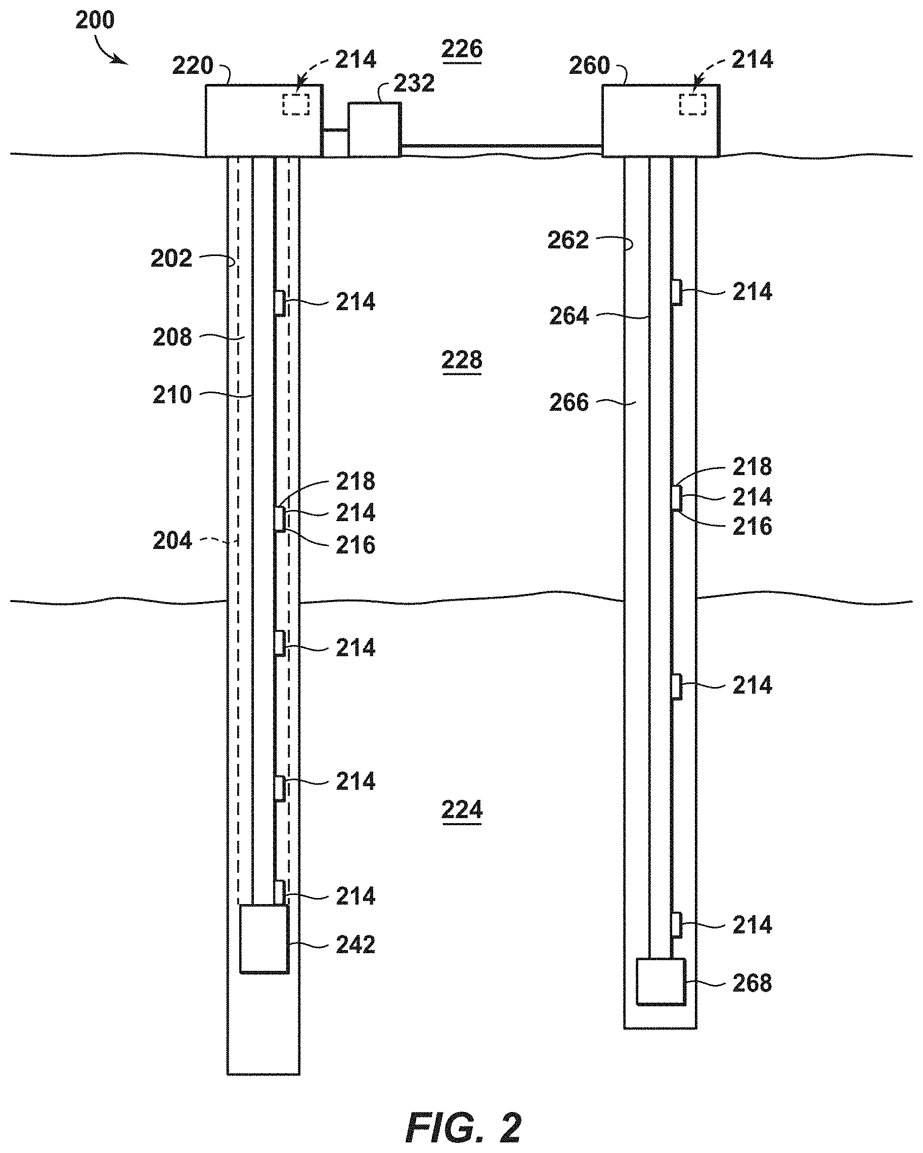
FIG. 2 is another exemplary schematic representation of a well configured to utilize the methods according to the present disclosure.
FIGS. 3A and 3B are exemplary views of communications nodes of FIG. 2.
FIG. 4 is an exemplary flow chart in accordance with an embodiment of the present techniques.
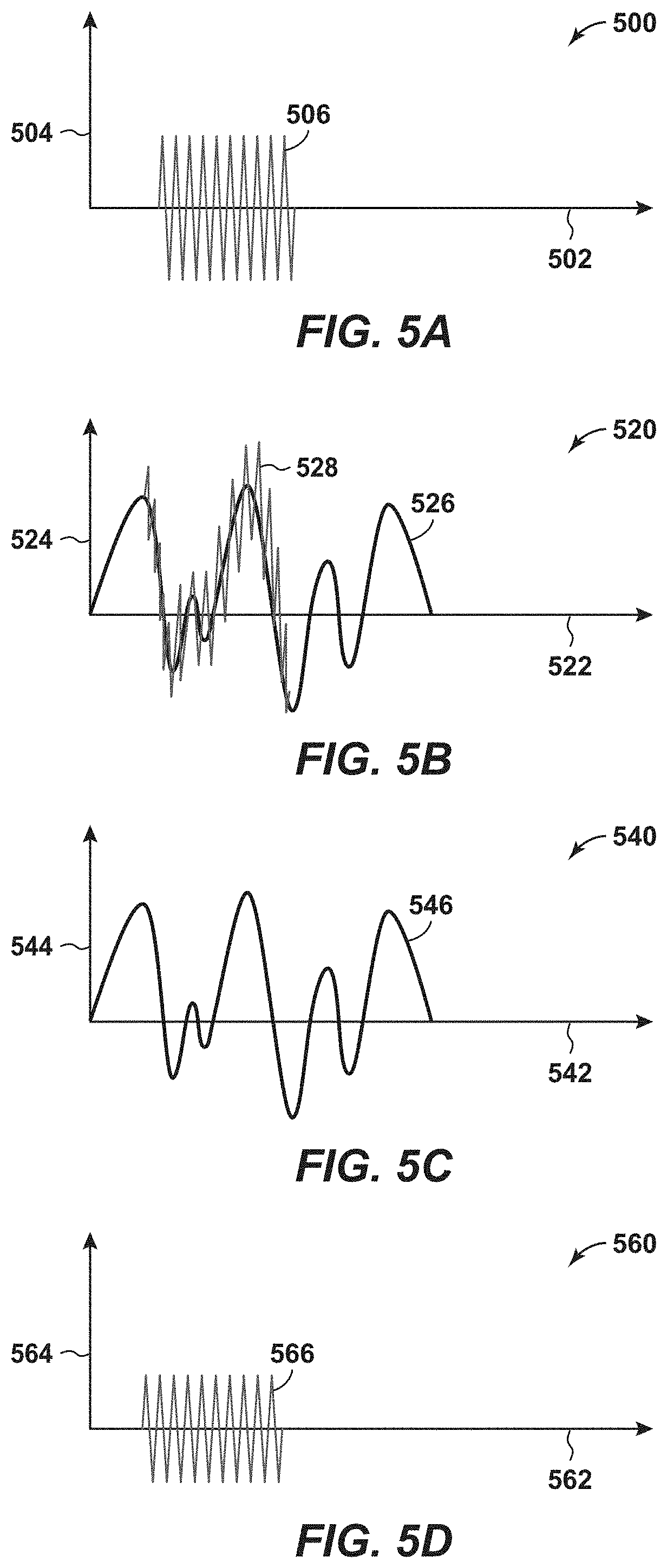
FIGS. 5A, 5B, 5C and 5D are exemplary diagrams of an acoustic communication signals used in a hydrocarbon system.
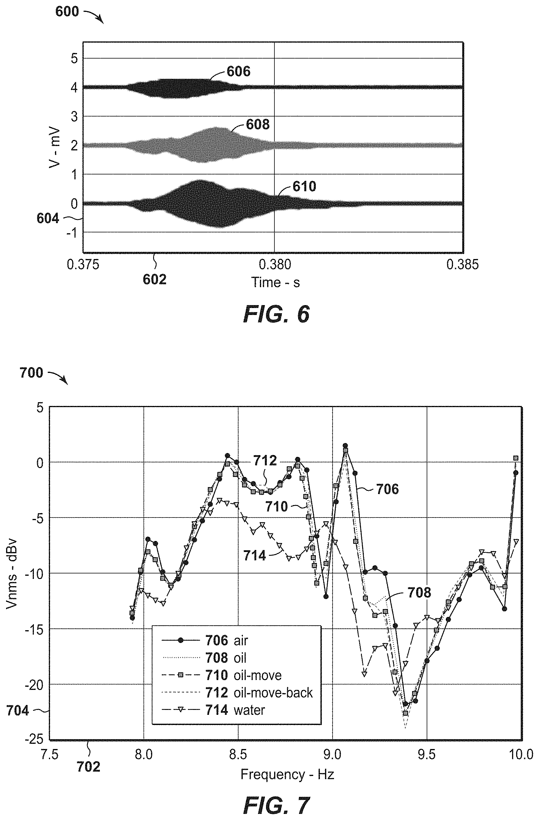
FIG. 6 is an exemplary diagram of an acoustic signal in various environments.
FIG. 7 is an exemplary diagram of an acoustic signal in various environments.
FIG. 8 is an exemplary diagram of a time domain signal in accordance with an embodiment of the present techniques.
FIG. 9 is yet another exemplary frequency domain signal in accordance with an embodiment of the present techniques.
DETAILED DESCRIPTION
In the following detailed description section, the specific embodiments of the present disclosure are described in connection with preferred embodiments. However, to the extent that the following description is specific to a particular embodiment or a particular use of the present disclosure, this is intended to be for exemplary purposes only and simply provides a description of the exemplary embodiments. Accordingly, the disclosure is not limited to the specific embodiments described below, but rather, it includes all alternatives, modifications, and equivalents falling within the true spirit and scope of the appended claims.
Various terms as used herein are defined below. To the extent a term used in a claim is not defined below, it should be given the broadest definition persons in the pertinent art have given that term as reflected in at least one printed publication or issued patent.
The articles "the", "a", and "an" are not necessarily limited to mean only one, but rather are inclusive and open ended so as to include, optionally, multiple such elements.
The directional terms, such as "above", "below", "upper", "lower", etc., are used for convenience in referring to the accompanying drawings. In general, "above", "upper", "upward" and similar terms refer to a direction toward the earth's surface along a wellbore, and "below", "lower", "downward" and similar terms refer to a direction away from the earth's surface along the wellbore. Continuing with the example of relative directions in a wellbore, "upper" and "lower" may also refer to relative positions along the longitudinal dimension of a wellbore rather than relative to the surface, such as in describing both vertical and horizontal wells.
As used herein, the term "and/or" placed between a first entity and a second entity means one of (1) the first entity, (2) the second entity, and (3) the first entity and the second entity. Multiple elements listed with "and/or" should be construed in the same fashion, i.e., "one or more" of the elements so conjoined. Other elements may optionally be present other than the elements specifically identified by the "and/or" clause, whether related or unrelated to those elements specifically identified. Thus, as a non-limiting example, a reference to "A and/or B", when used in conjunction with open-ended language such as "comprising" can refer, in one embodiment, to A only (optionally including elements other than B); in another embodiment, to B only (optionally including elements other than A); in yet another embodiment, to both A and B (optionally including other elements). As used herein in the specification and in the claims, "or" should be understood to have the same meaning as "and/or" as defined above. For example, when separating items in a list, "or" or "and/or" shall be interpreted as being inclusive, i.e., the inclusion of at least one, but also including more than one, of a number or list of elements, and, optionally, additional unlisted items. Only terms clearly indicated to the contrary, such as "only one of" or "exactly one of," or, when used in the claims, "consisting of," will refer to the inclusion of exactly one element of a number or list of elements. In general, the term "or" as used herein shall only be interpreted as indicating exclusive alternatives (i.e., "one or the other but not both") when preceded by terms of exclusivity, such as "either," "one of," "only one of," or "exactly one of".
As used herein, "about" refers to a degree of deviation based on experimental error typical for the particular property identified. The latitude provided the term "about" will depend on the specific context and particular property and can be readily discerned by those skilled in the art. The term "about" is not intended to either expand or limit the degree of equivalents which may otherwise be afforded a particular value. Further, unless otherwise stated, the term "about" shall expressly include "exactly," consistent with the discussion below regarding ranges and numerical data.
As used herein, "any" means one, some, or all indiscriminately of whatever quantity.
As used herein, "at least one," in reference to a list of one or more elements, should be understood to mean at least one element selected from any one or more of the elements in the list of elements, but not necessarily including at least one of each and every element specifically listed within the list of elements and not excluding any combinations of elements in the list of elements. This definition also allows that elements may optionally be present other than the elements specifically identified within the list of elements to which the phrase "at least one" refers, whether related or unrelated to those elements specifically identified. Thus, as a non-limiting example, "at least one of A and B" (or, equivalently, "at least one of A or B," or, equivalently "at least one of A and/or B") can refer, in one embodiment, to at least one, optionally including more than one, A, with no B present (and optionally including elements other than B); in another embodiment, to at least one, optionally including more than one, B, with no A present (and optionally including elements other than A); in yet another embodiment, to at least one, optionally including more than one, A, and at least one, optionally including more than one, B (and optionally including other elements). The phrases "at least one", "one or more", and "and/or" are open-ended expressions that are both conjunctive and disjunctive in operation. For example, each of the expressions "at least one of A, B and C", "at least one of A, B, or C", "one or more of A, B, and C", "one or more of A, B, or C" and "A, B, and/or C" means A alone, B alone, C alone, A and B together, A and C together, B and C together, or A, B and C together.
As used herein, "based on" does not mean "based only on", unless expressly specified otherwise. In other words, the phrase "based on" describes both "based only on," "based at least on," and "based at least in part on."
As used herein, "clock tick" refers to a fundamental unit of time in a digital processor. For example, one clock tick equals the inverse of the effective clock speed that governs operation of the processor. Specifically, one clock tick for a 1 MHz effective clock speed is equal to one microsecond. As another example, one clock tick may be equivalent to the minimum amount of time involved for a scalar processor to execute one instruction. A processor may operate at various effective clock speeds, and, as such, the amount of time equivalent to one clock tick may vary, but a fractional clock tick is not possible.
As used herein, "conduit" refers to a tubular member forming a physical channel through which something is conveyed. The conduit may include one or more of a pipe, a manifold, a tube or the like, or the liquid contained in the tubular member. Alternately, conduit refers to an acoustic channel of liquid which may, for example, exist between the formation and a tubular.
As used herein, "couple" refers to an interaction between elements and is not meant to limit the interaction to direct interaction between the elements and may also include indirect interaction between the elements described. Couple may include other terms, such as "connect", "engage", "attach", or any other suitable terms.
As used herein, "determining" encompasses a wide variety of actions and therefore "determining" can include calculating, computing, processing, deriving, investigating, looking up (e.g., looking up in a table, a database or another data structure), ascertaining and the like. Also, "determining" can include receiving (e.g., receiving information), accessing (e.g., accessing data in a memory) and the like. Also, "determining" can include resolving, selecting, choosing, establishing and the like.
As used herein, "one embodiment," "an embodiment," "some embodiments," "one aspect," "an aspect," "some aspects," "some implementations," "one implementation," "an implementation," or similar construction means that a particular component, feature, structure, method, or characteristic described in connection with the embodiment, aspect, or implementation is included in at least one embodiment and/or implementation of the claimed subject matter. Thus, the appearance of the phrases "in one embodiment" or "in an embodiment" or "in some embodiments" (or "aspects" or "implementations") in various places throughout the specification are not necessarily all referring to the same embodiment and/or implementation. Furthermore, the particular features, structures, methods, or characteristics may be combined in any suitable manner in one or more embodiments or implementations.
As used herein, "event" is used herein to mean a detection of a change in a communication environment along the conduit, such as a tubular member and/or any associated liquid. The event may include a change within a wellbore, a detection of a local failure in communication, a failure to operate properly, a manual trigger, and/or a lapse of a time period.
As used herein, "exemplary" is used exclusively herein to mean "serving as an example, instance, or illustration." Any embodiment described herein as "exemplary" is not necessarily to be construed as preferred or advantageous over other embodiments.
As used herein, "formation" refers to any definable subsurface region. The formation may contain one or more hydrocarbon-containing layers, one or more non-hydrocarbon containing layers, an overburden, and/or an underburden of any geologic formation.
As used herein, "hydrocarbons" are generally defined as molecules formed primarily of carbon and hydrogen atoms such as oil and natural gas. Hydrocarbons may also include other elements or compounds, such as, but not limited to, halogens, metallic elements, nitrogen, oxygen, sulfur, hydrogen sulfide (H.sub.2S), and carbon dioxide (CO.sub.2). Hydrocarbons may be produced from hydrocarbon reservoirs through wells penetrating a hydrocarbon containing formation. Hydrocarbons derived from a hydrocarbon reservoir may include, but are not limited to, petroleum, kerogen, bitumen, pyrobitumen, asphaltenes, tars, oils, natural gas, or combinations thereof. Hydrocarbons may be located within or adjacent to mineral matrices within the earth, termed reservoirs. Matrices may include, but are not limited to, sedimentary rock, sands, silicilytes, carbonates, diatomites, and other porous media.
As used herein, "hydrocarbon exploration" refers to any activity associated with determining the location of hydrocarbons in subsurface regions. Hydrocarbon exploration normally refers to any activity conducted to obtain measurements through acquisition of measured data associated with the subsurface formation and the associated modeling of the data to identify potential locations of hydrocarbon accumulations. Accordingly, hydrocarbon exploration includes acquiring measurement data, modeling of the measurement data to form subsurface models, and determining the likely locations for hydrocarbon reservoirs within the subsurface. The measurement data may include seismic data, gravity data, magnetic data, electromagnetic data, and the like. The hydrocarbon exploration activities may include drilling exploratory wells.
As used herein, "hydrocarbon development" refers to any activity associated with planning of extraction and/or access to hydrocarbons in subsurface regions. Hydrocarbon development normally refers to any activity conducted to plan for access to and/or for production of hydrocarbons from the subsurface formation and the associated modeling of the data to identify preferred development approaches and methods. By way of example, hydrocarbon development may include modeling of the subsurface formation and extraction planning for periods of production, determining and planning equipment to be utilized and techniques to be utilized in extracting the hydrocarbons from the subsurface formation, and the like.
As used herein, "hydrocarbon fluids" refers to a hydrocarbon or mixtures of hydrocarbons that are gases or liquids. For example, hydrocarbon fluids may include a hydrocarbon or mixtures of hydrocarbons that are gases or liquids at formation conditions, at processing conditions, or at ambient conditions (20.degree. Celsius (C) and 1 atmospheric (atm) pressure). Hydrocarbon fluids may include, for example, oil, natural gas, gas condensates, coal bed methane, shale oil, shale gas, and other hydrocarbons that are in a gaseous or liquid state.
As used herein, "hydrocarbon operations" refers to any activity associated with hydrocarbon exploration, hydrocarbon development, collection of wellbore data, and/or hydrocarbon production. It may also include the midstream pipelines and storage tanks, or the downstream refinery and distribution operations. By way of example, the hydrocarbon operations may include managing the communications for the wellbore through the communication nodes by utilizing the tubular members, such as drilling string and/or casing.
As used herein, "hydrocarbon production" refers to any activity associated with extracting hydrocarbons from subsurface location, such as a well or other opening. Hydrocarbon production normally refers to any activity conducted to form the wellbore along with any activity in or on the well after the well is completed. Accordingly, hydrocarbon production or extraction includes not only primary hydrocarbon extraction, but also secondary and tertiary production techniques, such as injection of gas or liquid for increasing drive pressure, mobilizing the hydrocarbon or treating by, for example, chemicals, hydraulic fracturing the wellbore to promote increased flow, well servicing, well logging, and other well and wellbore treatments.
As used herein, "mode" refers to a setting or configuration associated with the operation of communication nodes in a communication network. For example, the mode may include a setting for acoustical compression wave, acoustical shear wave, or any combination thereof.
As used herein, "monitored section" and "monitored sections" refer to locations along the tubular members that include sensors and/or are regions of interest.
As used herein, "unmonitored section" and "unmonitored sections" refer to locations along the tubular members that do not include sensors and/or are not regions of interest.
As used herein, "operatively connected" and/or "operatively coupled" means directly or indirectly connected for transmitting or conducting information, force, energy, or matter.
As used herein, "optimal", "optimizing", "optimize", "optimality", "optimization" (as well as derivatives and other forms of those terms and linguistically related words and phrases), as used herein, are not intended to be limiting in the sense of requiring the present invention to find the best solution or to make the best decision. Although a mathematically optimal solution may in fact arrive at the best of all mathematically available possibilities, real-world embodiments of optimization routines, methods, models, and processes may work towards such a goal without ever actually achieving perfection. Accordingly, one of ordinary skill in the art having benefit of the present disclosure will appreciate that these terms, in the context of the scope of the present invention, are more general. The terms may describe one or more of: 1) working towards a solution which may be the best available solution, a preferred solution, or a solution that offers a specific benefit within a range of constraints; 2) continually improving; 3) refining; 4) searching for a high point or a maximum for an objective; 5) processing to reduce a penalty function; 6) seeking to maximize one or more factors in light of competing and/or cooperative interests in maximizing, minimizing, or otherwise controlling one or more other factors, etc.
As used herein, "potting" refers to the encapsulation of electrical components with epoxy, elastomeric, silicone, or asphaltic or similar compounds for the purpose of excluding moisture or vapors. Potted components may or may not be hermetically sealed.
As used herein, "range" or "ranges", such as concentrations, dimensions, amounts, and other numerical data may be presented herein in a range format. It is to be understood that such range format is used merely for convenience and brevity and should be interpreted flexibly to include not only the numerical values explicitly recited as the limits of the range, but also to include all the individual numerical values or sub-ranges encompassed within that range as if each numerical value and sub-range is explicitly recited. For example, a range of about 1 to about 200 should be interpreted to include not only the explicitly recited limits of 1 and about 200, but also to include individual sizes such as 2, 3, 4, etc. and sub-ranges such as 10 to 50, 20 to 100, etc. Similarly, it should be understood that when numerical ranges are provided, such ranges are to be construed as providing literal support for claim limitations that only recite the lower value of the range as well as claims limitation that only recite the upper value of the range. For example, a disclosed numerical range of 10 to 100 provides literal support for a claim reciting "greater than 10" (with no upper bounds) and a claim reciting "less than 100" (with no lower bounds).
As used herein, "sealing material" refers to any material that can seal a cover of a housing to a body of a housing sufficient to withstand one or more downhole conditions including but not limited to, for example, temperature, humidity, soil composition, corrosive elements, pH, and pressure.
As used herein, "sensor" includes any electrical sensing device or gauge. The sensor may be capable of monitoring or detecting pressure, temperature, fluid flow, vibration, resistivity, or other formation data. Alternatively, the sensor may be a position sensor.
As used herein, "stream" refers to fluid (e.g., solids, liquid and/or gas) being conducted through various regions, such as equipment and/or a formation. The equipment may include conduits, vessels, manifolds, units or other suitable devices.
As used herein, "subsurface" refers to geologic strata occurring below the earth's surface.
As used herein, "telemetry diagnostic data", "diagnostic telemetry data", or "telemetry data" refer to data associated with the communication nodes exchanging information. The telemetry data may be exchanged for the purpose of assessing and proving or otherwise optimizing the communication. By example, this may include frequency and/or amplitude information.
As used herein, "physical layer" refers to the lowest layer of the Open Systems Interconnection model (OSI model) maintained by the identification ISO/IEC 7498-1. The OSI model is a conceptual model that partitions a communication system into abstraction layers. The physical layer defines basic electrical and physical specifications of the network such as acoustic frequency band, radio-frequency (RF) frequency band, acoustic versus electromagnetic communication, and other electrical and physical aspects of the communication.
As used herein, "direct mapping" refers to establishing a correspondence between communication frequencies and symbolic information such that particular communication frequencies represent a particular piece of symbolic information. Examples of symbolic information include, but are not limited to, the letters in alphabet or specific arrangements of bits in a computer memory. By way of example, direct mapping in an acoustic telemetry system may include each 100 kHz tone representing the letter "A", each 102 kHz tone representing the letter "B", each 104 kHz tone representing the letter "C", and so on. By contrast, "spread spectrum" may involve a correspondence between communication frequencies and symbolic information that changes repeatedly and in rapid fashion, such that, by way of example, a 100 kHz tone may represent the letter "A" and a 104 kHz tone may represent the letter "B" and a 102 kHz tone may represent the letter "C", then a 110 kHz tone may represent the letter "A" and a 112 kHz tone may represent the letter "B" and a 114 kHz tone may represent the letter "C", then a 90 kHz tone may represent the letter "A" and a 84 kHz tone may represent the letter "B" and a 96 kHz tone may represent the letter "C", and so on. In addition, the direct mapping may not change, while spread spectrum may change.
As used herein, "frequency combining" refers to aggregating similar frequencies by dividing the range of possible frequencies into a number of sections and classifying all frequencies within any one section as occurrences of a single frequency. It will be apparent to a person skilled in the computational arts that the totality of possible frequencies may be excessively large, leading to an excessive degree of computational complexity inherent in analysis of the frequencies, and that frequency combining can limit the number of possibilities to reduce the computational complexity inherent in analysis of the possibilities to an acceptable level. The limited number of possibilities resulting from frequency combining may be referred to as the "combined frequencies". The cadence of digital clock ticks acts as an upper bound on the number of possible combined frequencies in all cases.
As used herein, "signal strength" refers to a quantitative assessment of the suitability of a characteristic for a particular purpose. A characteristic may be an amplitude, a Fast Fourier Transform (FFT) magnitude, a signal-to-noise ratio (SNR), a zero crossing (ZCX) quality, a histogram quantity, an occurrence count, a margin or proportion above a baseline, or any other suitable measurement or calculation. By way of example, a histogram representing ZCX occurrence counts by period may assess ZCX signal strength for each period by dividing the occurrence count for each period by the maximum occurrence count in the histogram such that the ZCX signal strength for the period having the maximum occurrence count is 1 and this is the highest ZCX signal strength among all the periods in the histogram.
As used herein, "tubular member", "tubular section" or "tubular body" refer to any pipe, such as a joint of casing, a portion of a liner, a drill string, a production tubing, an injection tubing, a pup joint, a buried pipeline, underwater piping, or above-ground piping. Solid lines therein, and any suitable number of such structures and/or features may be omitted from a given embodiment without departing from the scope of the present disclosure.
As used herein, "wellbore" or "downhole" refers to a hole in the subsurface made by drilling or insertion of a conduit into the subsurface. A wellbore may have a substantially circular cross section, or other cross-sectional shape. As used herein, the term "well," when referring to an opening in the formation, may be used interchangeably with the term "wellbore."
As used herein, "well data" or "field data" may include seismic data, electromagnetic data, resistivity data, gravity data, well log data, core sample data, and combinations thereof. The field data may be obtained from memory or from the equipment in various wellbores and associated production equipment. The well data may also include the data associated with the equipment installed within the wellbore and the configuration of the wellbore equipment. For example, the well data may include the composition of the tubular members, thickness of the tubular members, length of the tubular members, fluid composition within the wellbore, formation properties, cementation within the wellbore and/or other suitable properties associated with the wellbore.
As used herein, "zone", "region", "container", or "compartment" is a defined space, area, or volume contained in the framework or model, which may be bounded by one or more objects or a polygon encompassing an area or volume of interest. The volume may include similar properties.
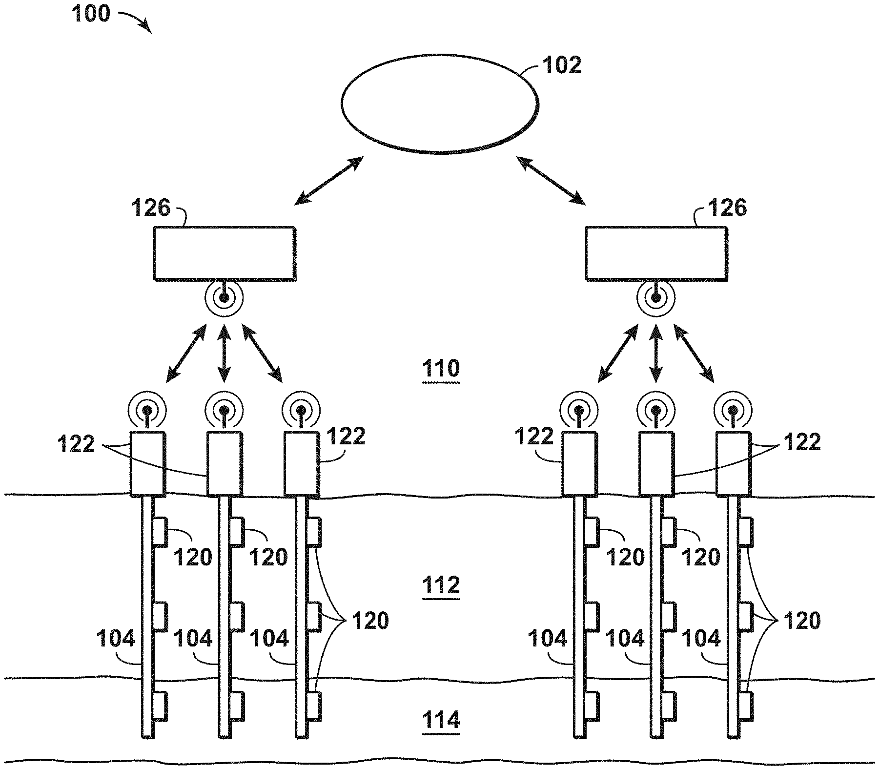
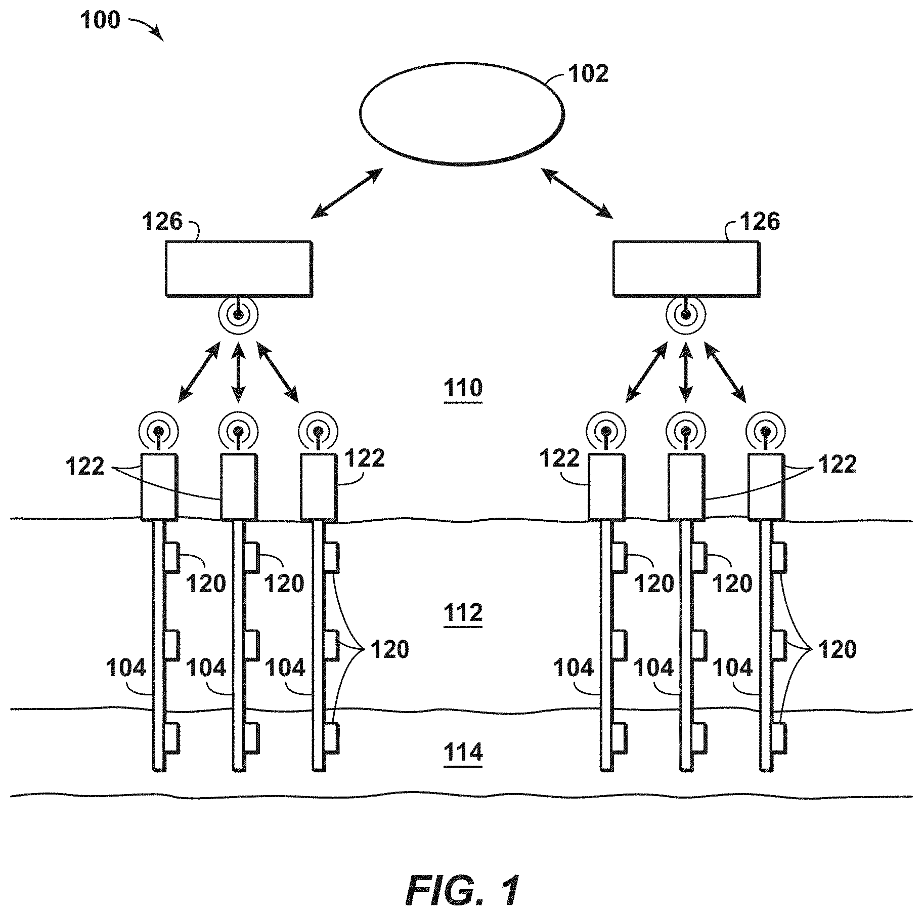
The exchange of information may be used to manage the operations for different technologies. By way of example, the communication network may include communication nodes disposed along one or more tubular members. The communication nodes may be distributed along casing or tubing within a wellbore, along a subsea conduit and/or along a pipeline, to enhance associated operations. Further, the communication nodes may communicate for various wellbores, subsea conduits and/or pipelines. To exchange information, the communication network may include physically connected communication nodes, wirelessly connected communication nodes or a combination of physically connected communication nodes and wirelessly connected communication nodes.
By way of example, the communication network may be used for data exchanges of operational data, which may be used for real-time or concurrent operations involving hydrocarbon exploration operations, hydrocarbon development operations, and/or hydrocarbon production operations, for example. In hydrocarbon operations, the system or method may involve communicating via a downhole network including various communication nodes spaced-apart along a length of tubular members, which may be a tone transmission medium (e.g., conduits). The communication nodes may communicate with each other to manage the exchange of data within the wellbore and with a computer system that is utilized to manage the hydrocarbon operations. Further, the communication network may involve the exchange of data between communication nodes from different wellbores, which may be coupled together by gateways. By way of example, the communication network may involve transmitting and/or receiving signals or tones via one or more frequencies of acoustic tones in the form of data packets via the tone transmission medium. The downhole wireless communication through the tubular members, such as casing and/or production tubing, may be beneficial for enhancing hydrocarbon operations, such as optimizing drilling, optimizing and managing completions, and performing well management. In such communications, the communication network may include communication nodes that utilize ultrasonic acoustic frequencies to exchange information.
In certain configurations, the communication nodes may include a housing that isolates various components from the associated environment, such as a surface environment and/or a wellbore environment. In particular, the communication nodes may include one or more encoding components, which may be configured to generate and/or to induce one or more acoustic tones within tone transmission medium, such as a tubular member or liquid inside the tubular member. Alternately, conduit refers to an acoustic channel of liquid which may, for example, exist between the formation and a tubular member. In addition, the communication nodes may include one or more decoding components, which may be configured to receive and/or decode acoustic tones from the tone transmission medium. The communication nodes may include one or more power supplies configured to supply energy to the other components, such as batteries. The communication nodes may include one or more sensors, which may be configured to obtain measurement data associated with the downhole environment and/or the formation. The communication nodes may include relatively small transducers to lessen the size of the communication nodes, such that they may be disposed or secured to locations having limited clearance, such as between successive layers of downhole tubular members. As an example, small acoustic transducers may be configured to transmit and/or receive tones.
In one configuration, the present techniques may involve a low-cost method to monitor well production performance for effective and efficient management of unconventional hydrocarbon fields. The desirable parameters to be monitored may include, for individual well, the material being produced (e.g., oil, gas, water, and sand), rate of production of each phase, and temporal trend of the production, and for a portion or whole hydrocarbon field, the temporal and spatial distribution of the production and performance of each of the wells in the hydrocarbon field. While wireless communication networks may be used for sensing and monitoring, conventional sensing technologies involve intrusive sensing methods for flow measurement, such as differential pressure sensing of flow-restrictive devices (e.g., orifice, pitot-tube, and the like), internal rotating devices (e.g., turbines), and radioactive methods for material identification. The present techniques utilize a wireless monitoring system that incorporates non-intrusive acoustic sensors that may be part of a communication node and wireless network technologies, which may be installed on or within a wellhead with minimal installation cost. The communication nodes having sensors or sensing components may be further extended to the downhole environment, installed on production tubing and/or casing to monitor the production from multiple zones, which may also be on multiple wells. The remote monitoring data from each individual well in a hydrocarbon field may be aggregated for effective and efficient management of the hydrocarbon field.
In certain configurations, the present techniques provides a measurement and information management system having various features. As a first feature, the system may include a non-intrusive acoustic measurement device that may be disposed on a tubular member (e.g., glued, welded, and/or mechanically secured) or wellhead without interrupting the production operations and may be performed with minimal installation effort.
As a second feature, the present techniques may include a communication node that is a self-contained device, which may be inserted into a threaded port that has direct, or indirect acoustic coupling to a production tubular, casing annulus or other maintenance or production port on a wellhead or other surface equipment. Such communication node may be installed on a tree associated with the respective wellbore. Such communication nodes may be useful for both injection equipment (e.g., injection of water, gas, hydraulic fracture fluids, proppants, and/or tracers) and/or production equipment (with or without artificial lift pumps or gas lift mechanisms).
A third feature is that the communication nodes may be equipped with a set of sensors, signal processing and data fusion capability for real-time measurement of the well production or injection rates including the material be produced and flow rate of each phase.
As a fourth feature, the communication network may include one or more gateway devices or nodes to manage the communication to the control unit. For example, the communication nodes may be equipped with wireless communication capability that are used for communicating measurement data to a gateway, and then from the gateway to a central server or control unit via long-range communication to form a sensor network of a hydrocarbon field. The topside node and/or gateway node may also store sensor data from various nodes for deferred transmission to remote users. Additionally, the gateways may replicate one another's data to facilitate data fusion and provide fault tolerance against a subset of the gateway devices becoming non-functional.
As a fifth feature, the communication nodes may be equipped with external power sources and/or a rechargeable power supply. For example, certain communication nodes, which are above the surface and/or associated with the tree may be equipped with a rechargeable battery with solar panel and/or wind-turbine for self-sufficient power. Other examples include communication nodes that are powered by vibration, or direct connection to local power source (e.g. that used for artificial lift pumps). The gateway node may optimize wide area transmissions (e.g., 3G, 4G, satellite, coaxial trunk, fixed wireless, microwave, etc.) for times when maximum energy is available (e.g., windy times, maximum sunlight, when battery has a certain minimum charge level, etc.). Additionally, the gateway devices may engage in staggered sleep modes, such that some communication nodes sleep, while others communication nodes are available to receive sensor data and as sleeping gateway node wakes, then the data may be replicated, such that the gateway node ultimately has a complete set of sensor data. The staggered sleep mode, data replication, and deferred transmission may be useful.
In a sixth feature, the housing for the communication node may be adjusted based on the associated environment. For example, the housing for communication nodes above the surface may be an explosion-proof enclosure for classified hazardous areas.
A seventh feature may include a communication network with capabilities of continuous updating well data for the various wellbores and may share the updated data to enhance the performance of the overall field measurements. The system may take action based on the 3D production profile to affect operation of the well or associated tools, such as changing the activation times and duty cycle of specific pump jacks in the field. The system may also change production controls in the field, such as taking actions causing field production to decrease when a nearby storage tank is filled beyond a certain level, and increasing field production when a nearby storage tank is filled to less than a certain level.
In one configuration, a communication node may include an acoustic sensor for nonintrusive measurement of material phase and flow rate through a portion of a well or through a portion of the production equipment. To obtain production data for the hydrocarbon field, the communication nodes may be used to measure and to estimate the material phases and their flow rates in real time or concurrently at the respective locations for each individual well. To obtain the data, the sensing method used in the communication nodes may involve a pair of acoustic transducers attached on tubular member and separated over a specific distance. The transducers may include a narrow-band ultrasonic transmitter that generates waves of certain ultrasonic frequencies either continuously, within certain windows or as needed, and a broadband receiver that may be used to sense both audible and ultrasonic vibration. Alternatively, the configuration may include the use of transmitter and receiver pair at an injection wellhead to monitor injection fluids and/or returned fluids or multiphase (e.g., gas, liquid, solid) flows.
In another configuration, the communication node may perform signal processing and data fusion. In this method, the transmitter generates waves of pre-selected one or more ultrasonic frequencies, and the receiver acquires the vibration from the tubular member, which is superposition of ultrasonic waves from the transmitter and other noises including flow-induced noise and background noise. The composite signals at the receiver may be separated into two components, which are the ultrasonic component and the audible component. The composite signal may be separated by one or more filtering methods. Extracted ultrasonic signals may be related to the property of the medium or fluid flowing inside the tubular member, and the audible signals may be related to the flow velocity within the tubular member. With proper calibration, ultrasonic and audible signals may be used to detect both fluid or medium (e.g., gas, water and/or oil) and flow velocity inside the tubular member at the same time. Thus, the average flow rate of each phase (e.g., gas, water, and/or oil) can be estimated over a given time interval.
In yet another configuration, the present techniques may be used for water and/or gas breakthrough during production operations. Water and/or gas breakthrough is one aspect that is managed in hydrocarbon operations, such as reservoir management. The communication network provides monitoring capability of water and/or gas breakthrough events. A series of communication nodes may include sensors that may be integrated with the hydrocarbon system to capture the changes before and after the breakthrough of the monitored fluid. The sensors in the communication nodes may include pressure, temperature, resistivity, capacitance, pH, chemical sensors. The event time and location may be recorded and the data may be relayed to the surface for production optimization. The present techniques may involve customizing data dissemination based on a priority (e.g., determined according to certain criteria, such as sending certain data sooner.)
In still yet another configuration, the present techniques may be used for slug detection. Some wells may experience slugging issues because of changing flow conditions. Large and frequent slugging may damage production facilities. Slugging also results in higher bottom hole pressure and thus decrease the production. The communication network may include communication disposed along the tubular members, such as production tubing, may monitor the slugging events, including location, frequency, and amplitude. The data may be collected through various sensors in one or more communication nodes, including pressure, acoustics, strain, capacitance, resistivity sensors, and the like. Further, elimination procedure can be planned based on the monitoring data.
In a further configuration, the communication network may be used to manage the communication for the communication nodes. The communication nodes may include sensors in a hydrocarbon field and may be distributed in or associated with a large number of wells. The communication nodes may be organized into clusters based on either distance or homogeneity of the reservoir property and/or both. Within each cluster, the communication nodes can communicate the data to a gateway node with short-range wireless communication techniques, such as ZigBee. The gateway node for each cluster may communicate with a central server and/or a control unit, which may be coupled to the network by wired Ethernet, by wireless Wi-Fi and/or mobile wireless communication technologies (e.g., 3G or 4G . . . ).
In yet another configuration, the communication nodes may include network intelligence, and continuous learning for measurement improvement. In each communication node, the communication node may include network intelligence component. The network intelligence component may be embedded decision managing software agents in addition to multiple signal processing and data fusion algorithms. The network intelligence component may be configured to detect and remove abnormal data points, conduct self-diagnosis of communication node or sensor health and battery condition, selection of a different algorithm, technique, or method for different flow regimes (e.g., single phase or multiphase, homogenous or annular or plug flow, or pulsing flow or flow with sand). Further, the gateway nodes may also include embedded data managing agents that are configured to manage and aggregate the flow information from the well of the cluster, and communicate the data to the central server or control unit. Then, the control unit may include data managing software that provides capability of high-level data and information management. The communication node, the gateway node and control unit each have certain learning capabilities and may be configured to share the learning throughout whole network.
In addition, other configurations may use the present techniques to perform field-wise production and injection optimization. The distributed communication nodes on the production tubing may collect various information related with production. The information from each well may serves as the profile of the production conditions in the respective well. After combining the information from the whole hydrocarbon field, a three-dimensional (3D) production profile can be generated. By way of example, a water and/or gas breakthrough information (e.g., depth, location, direction, rate, and the like), the connectivity of adjacent wells may be derived. These information can be further used for injection planning, slugging elimination, or other optimization purposes. Valves in the hydrocarbon field can also be optimized to maintain the reservoir pressure to improve the overall field production.
In certain configurations, the communication device may include performing ultrasonic telemetry and sensing in specific frequency bands. As an example, the communication network may utilize low-frequency ranges and/or high-frequency ranges (e.g., may include low-frequency communication nodes and/or high-frequency communication nodes). The low-frequency communication nodes may be configured to transmit signals and to receive signals that are less than or equal to (.ltoreq.) 200 kHz, .ltoreq.100 kHz, .ltoreq.50 kHz, or .ltoreq.20 kHz. In particular, the low-frequency communication nodes may be configured to exchange signals in the range between 100 Hz and 20 kHz; in the range between 1 kHz and 20 kHz; and in the range between 5 kHz and 20 kHz. Other configurations may include low-frequency communication nodes, which may be configured to exchange signals in the range between 100 Hz and 200 kHz; in the range between 100 Hz and 100 kHz; in the range between 1 kHz and 200 kHz; in the range between 1 kHz and 100 kHz; in the range between 5 kHz and 100 kHz and in the range between 5 kHz and 200 kHz. The communication nodes may also include high-frequency communication nodes configured to transmit and receive signals that are greater than (>) 20 kHz, >50 kHz, >100 kHz or >200 kHz. Also, the high-frequency communication nodes may be configured to exchange signals in the range between greater than 20 kHz and 1 MHz, in the range between greater than 20 kHz and 750 kHz, in the range between greater than 20 kHz and 500 kHz. Other configurations may include high-frequency communication nodes, which may be configured to exchange signals in the range between greater than 100 kHz and 1 MHz; in the range between greater than 200 kHz and 1 MHz; in the range between greater than 100 kHz and 750 kHz; in the range between greater than 200 kHz and 750 kHz; in the range between greater than 100 kHz and 500 kHz; and in the range between greater than 200 kHz and 500 kHz.
In such configurations, the low frequency bands and/or high-frequency bands may utilize piezoelectric systems to enhance operations. The communication coupling device may include piezo transducers that may be coupled to the environment to be sensed (e.g., pulse echo from piezo assembly behind a thin steel wall and thus proximate flowing media, hydrates, sand, which may be within the tubular member). The configurations may include the use of acoustic or other transducer arrays spaced on an azimuth. Such transducer arrays may be used to launch single mode acoustic or vibrational waves that may be tailored for one or more of: (i) long distance telemetry, (ii) focusing the acoustic energy in steel tubular, or within media, or outside of surface of tubular, (iii) for one or more piezoelectric transducers, the termination properties, coupling to adjoining tubular members, and preferable acoustic wave properties that may be enhanced by the radial design versus a point or wide line attachment.
In still yet another configuration, the electronic circuits are present within the communication device (e.g., including the communication nodes) to process the collected measurement data, store the data for transmission, and conduct necessary on-board computation to simplify data for transmission. Local detection of faulty data, data compression, and automated communication with neighboring sensors may be carried out with the on-board electronics, signal processing components and microprocessor.
In another configuration, the communication nodes may include a communication node (e.g., configured to function as a transmitter and/or receiver) for data transmission to topside communication nodes or other devices. In other configurations, multiple different types of devices may be connected. For example, if it is an acoustic system, piezos may be facilitated as a transmitter and a receiver to relay data back to topside or other wireline tools. If it is an electromagnetic system, then radio-frequency receivers with communication frequency ranges may be integrated.
In other configurations, the communication network may include communication nodes (e.g., configured to function as a transmitter and/or receiver) that may be oriented to receive and/or transmit inside the tubular member, outside the tubular member and/or a combination thereof. The range of the communication nodes may be extended by broadcasting directly into the tubular member versus receiving and transmitting on the exterior of the tubular member. In addition, the reliability and quality of the acoustic transmission when broadcasting into the tubular member may be enhanced.
In addition, other configurations may include the communication network may include gateway nodes integrated into communication network, which may be used to manage a set of wells. Such an integration may enhance the operations of the system by managing the data from the different wells. The use of the gateway node may enhance reliability by efficiently managing the communication from various wells to the control unit.
The configuration may include various enhancements. For example, because the wells may be in a remote or difficult-to-access location, the gateway nodes may operate on battery power and/or be otherwise power constrained. To reduce maintenance, the gateway nodes may be configured to operate in a sleep mode for various time periods. Further, the sleep behavior (e.g., sleep mode, which may vary for time, duration, etc.) may be modified as a result of an adaptive learning method or recognized pattern. Further, the downhole communication nodes for multiple wells in a field may synchronize the sensors, such that the resulting data yields a three dimensional (3D) profile (e.g., spatially across the field at various depths). Further still, the system may be configured to learn the degree to which the inflow points on various wells impact one another. For example, a particular zone in well A may be strongly related to a range of zones associated with wells B and C, but only weakly related to other zones associated with wells B and C, and may be unrelated to well D. Further, these relationships may change over time, and the system (e.g., control unit or top nodes) may track the dynamic relationships. Based on the above, the system may use learned relationships in combination with certain current sensor data, to provide a proactive alert to designated operators. These alerts or notifications may help an operator or automated system perform an action to optimize ongoing production of a particular well or across a field of wells. For example, the production of a particular well may be halted or adjusted to stimulate production in several other wells at certain moments in time. Adding to the above, the system may generate 3D production contour maps and can generate animations to show the evolution of the 3D production contour over time.
By way of example, the sensors may include a fiber optics or other sensors. Using interpretation techniques, the data may be used to evaluate fluid composition and/or fluid type in the nearby formation. Assessing some of these properties may involve additional data or knowledge of the system (e.g., well data).
In one embodiment, a method of communicating data among a plurality of communication nodes in a communication network is described. The method comprising: obtaining field data for a hydrocarbon system; creating a communication network configuration based on the obtained field data for a communication network, wherein the communication network includes a plurality of communication nodes; configuring the plurality of communication nodes based on the communication network configuration; configuring a control unit based on the communication network configuration and configured to exchange data packets with the plurality of communication nodes; installing the communication nodes in the hydrocarbon system; and exchanging data packets to between the plurality of communication nodes and the control unit to perform hydrocarbon operations for the hydrocarbon system.
In other embodiments, one or more enhancements are described. The method may further comprising identifying one or more parameters to be measured for the hydrocarbon system; wherein one or more of the plurality of the communication nodes are configured to detect the one or more parameters; further comprising: obtaining measurements from one or more of the plurality of communication nodes, wherein the plurality of communication nodes are disposed along one or more tubular members, transmitting the obtained measurement from the one or more of the plurality of communication nodes to the control unit, and performing hydrocarbon operations based on the obtained measurements; wherein each of the one or more of the plurality of communication nodes is configured to detect one of water breakthrough, gas breakthrough and any combination thereof; wherein each of the one or more of the plurality of communication nodes is configured to measure one of detect pressure, temperature, resistivity, capacitance, pH, and any combination thereof; wherein each of the one or more of the plurality of communication nodes is configured to detect changes in fluid flow through one of the tubular members; wherein each of the one or more of the plurality of communication nodes is configured to measure one of pressure, acoustics, strain, capacitance, resistivity and any combination thereof; wherein installing the communication nodes in the hydrocarbon system comprises: disposing a first set of communication nodes from the plurality of communication nodes into a first well, disposing a first topside communication node from the plurality of communication nodes to a first tree associated with the first well, disposing a second set of communication nodes from the plurality of communication nodes into a second well, and disposing a second topside communication node from the plurality of communication nodes to a second tree associated with the second well; wherein the first topside communication node is configured to measure fluid flow from the first well; and/or wherein the second topside communication node is configured to measure fluid flow from the second well; wherein the first topside communication node is configured to measure fluid composition from the first well; and/or wherein the second topside communication node is configured to measure fluid composition from the second well; wherein one of the communication nodes in the first well is configured to measure fluid flow within the first well; and/or wherein one of the communication node in the second node is configured to measure fluid flow within the second well; wherein one of the communication nodes in the first well is configured to measure fluid composition within the first well; and/or wherein one of the communication nodes in the second well is configured to measure fluid composition from the second well; wherein one of the communication nodes in the first well is configured to measure temperature within the first well; and/or wherein one of the communication node in the second node is configured to measure temperature within the second well; wherein one of the communication nodes in the first well is configured to measure pressure within the first well; and/or wherein one of the communication nodes in the second well is configured to measure pressure from the second well; wherein the first topside communication node and the second topside communication node are each configured to communicate via one of radio frequencies, physical connections and any combination thereof and the communication nodes with the first well and second well are configured to communicate via acoustically; further comprising: configuring one or more gateway nodes based on the communication network configuration, wherein at least one of the one or more gateway nodes is configured to exchange data packets between the first topside communication node and the control unit based on the communication network configuration and to exchange data packets between the second topside communication node and the control unit based on the communication network configuration, installing the one or more gateway nodes in the hydrocarbon system, and exchanging data packets to between the first topside communication node and control unit via the at least one of the one or more gateway nodes and between the second topside communication node and control unit via the at least one of the one or more gateway nodes; wherein the creation of the communication network comprises selecting one of one or more frequency bands, one or more individual tones, one or more coding methods, and any combination thereof; wherein the communicating between the plurality of communication nodes comprises exchanging low-frequency signals that are less than or equal to (.ltoreq.) 20 kilohertz; wherein the communicating between the plurality of communication nodes comprises exchanging low-frequency signals that are in the range between 100 hertz and 20 kilohertz; wherein the communicating between the plurality of communication nodes comprises exchanging high-frequency signals that are greater than (>) 20 kilohertz; wherein the communicating between the plurality of communication nodes comprises exchanging high-frequency signals that are in the range between greater than 20 kilohertz and 1 megahertz; further comprising determining whether to adjust hydrocarbon operations based on the exchanged data packets to between the plurality of communication nodes and the control unit; further comprising performing the adjustment to hydrocarbon operations based on the determination; wherein the field data is associated with equipment installed within the wellbores and associated wellbore equipment; and/or further comprising modeling fluid compositions in the hydrocarbon system based on the data packets.
A hydrocarbon system is described. The system comprising: a plurality of wellbores in a hydrocarbon system; a plurality of tubular members disposed in the plurality of wellbores; a communication network associated with the hydrocarbon system, wherein the communication network comprises a plurality of communication nodes that are configured to communicate operational data between two or more of the plurality of communication nodes during hydrocarbon operations; and a control unit associated the hydrocarbon system and configured to exchange data packets with the plurality of communication nodes. Also, the communication network may comprise a plurality of communication nodes, a plurality of topside nodes and one or more gateway nodes that are configured to communicate operational data between two or more of the plurality of communication nodes during hydrocarbon operations, plurality of topside nodes and one or more gateway nodes.
Beneficially, the present techniques provide various enhancements to the operations. Accordingly, the present techniques may be further understood with reference to FIGS. 1 to 9, which are described further below.
FIG. 1 is an exemplary schematic representation of a hydrocarbon system 100 configured to utilize the methods according to the present techniques. The hydrocarbon system 100 is configured to utilize a network 102 having the proposed configuration of communication nodes 120 for various wells 104. The wells 104 includes a wellbore that extends from above the surface 110 to subsurface regions 112 and 114, which may include hydrocarbons. Each of the wellbores of the wells 104, which may include tubular sections, which may be formed of carbon steel, such as a casi
References
D00000
D00001
D00002
D00003
D00004
D00005
D00006
D00007
XML
uspto.report is an independent third-party trademark research tool that is not affiliated, endorsed, or sponsored by the United States Patent and Trademark Office (USPTO) or any other governmental organization. The information provided by uspto.report is based on publicly available data at the time of writing and is intended for informational purposes only.
While we strive to provide accurate and up-to-date information, we do not guarantee the accuracy, completeness, reliability, or suitability of the information displayed on this site. The use of this site is at your own risk. Any reliance you place on such information is therefore strictly at your own risk.
All official trademark data, including owner information, should be verified by visiting the official USPTO website at www.uspto.gov. This site is not intended to replace professional legal advice and should not be used as a substitute for consulting with a legal professional who is knowledgeable about trademark law.