Autofocus system for a conventional camera that uses depth information from an array camera
Venkataraman , et al.
U.S. patent number 10,674,138 [Application Number 16/179,796] was granted by the patent office on 2020-06-02 for autofocus system for a conventional camera that uses depth information from an array camera. This patent grant is currently assigned to FotoNation Limited. The grantee listed for this patent is FotoNation Limited. Invention is credited to Florian Ciurea, Paul Gallagher, Ankit K. Jain, Dan Lelescu, Gabriel Molina, Semyon Nisenzon, Kartik Venkataraman.


View All Diagrams
| United States Patent | 10,674,138 |
| Venkataraman , et al. | June 2, 2020 |
Autofocus system for a conventional camera that uses depth information from an array camera
Abstract
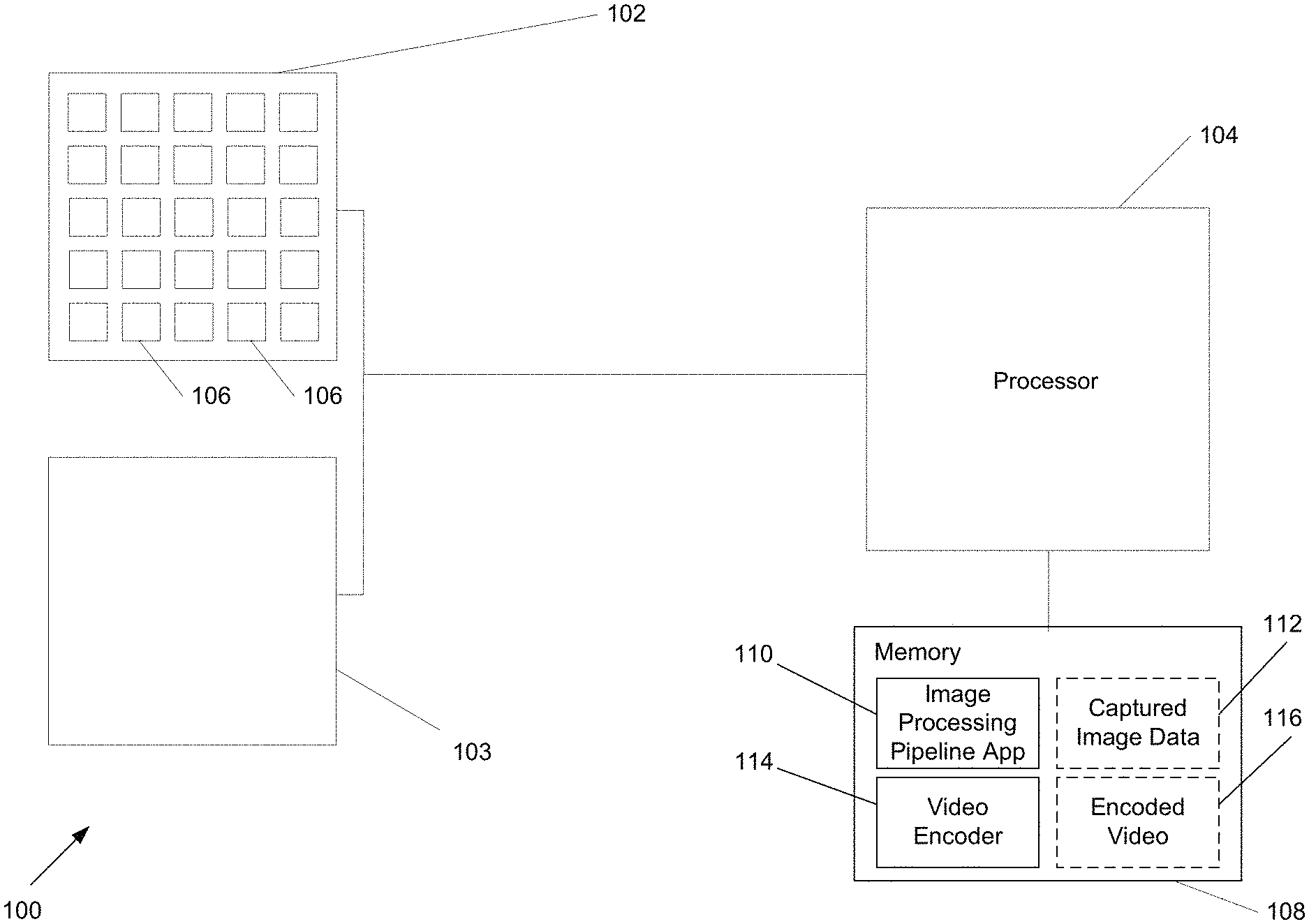
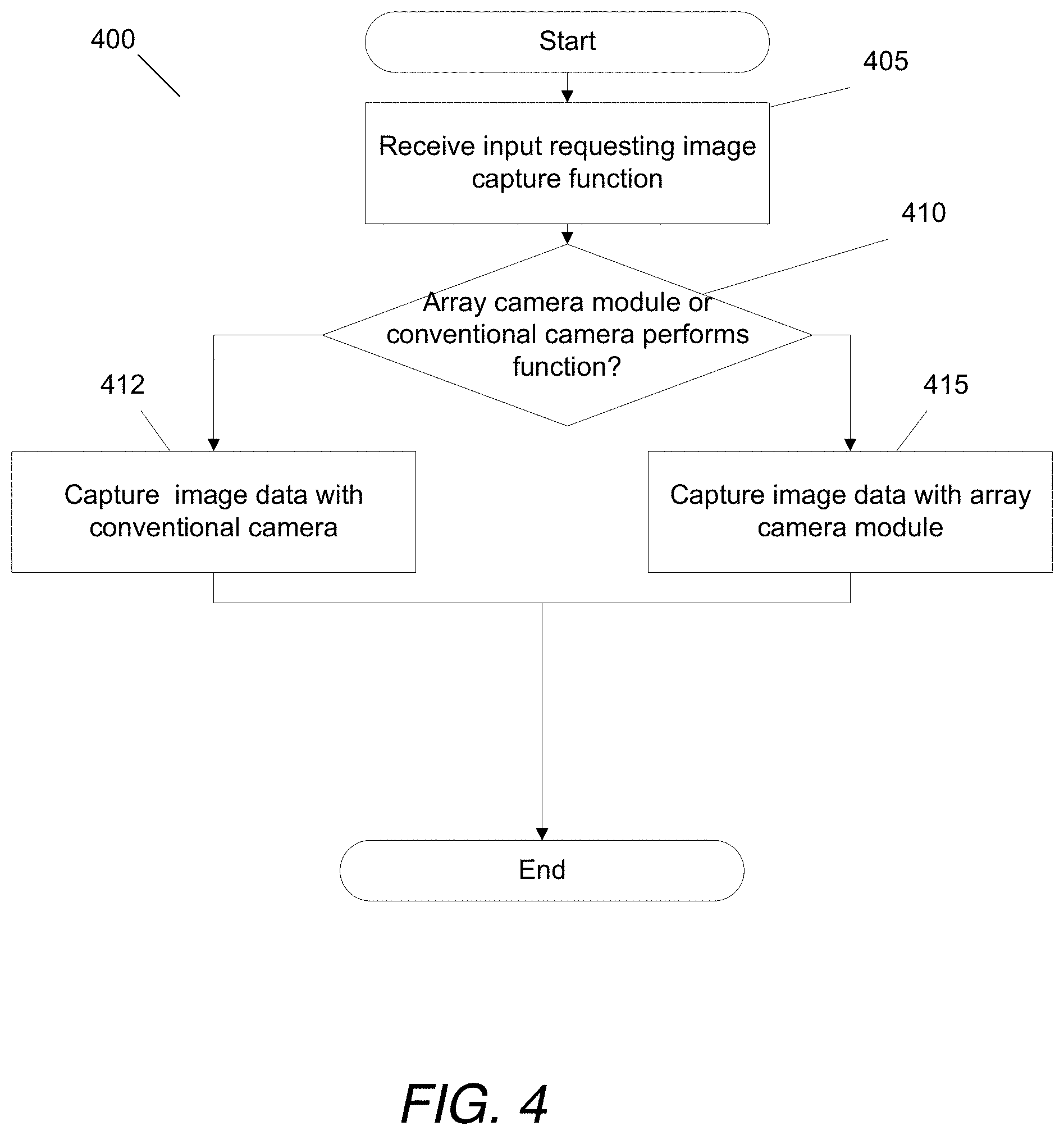
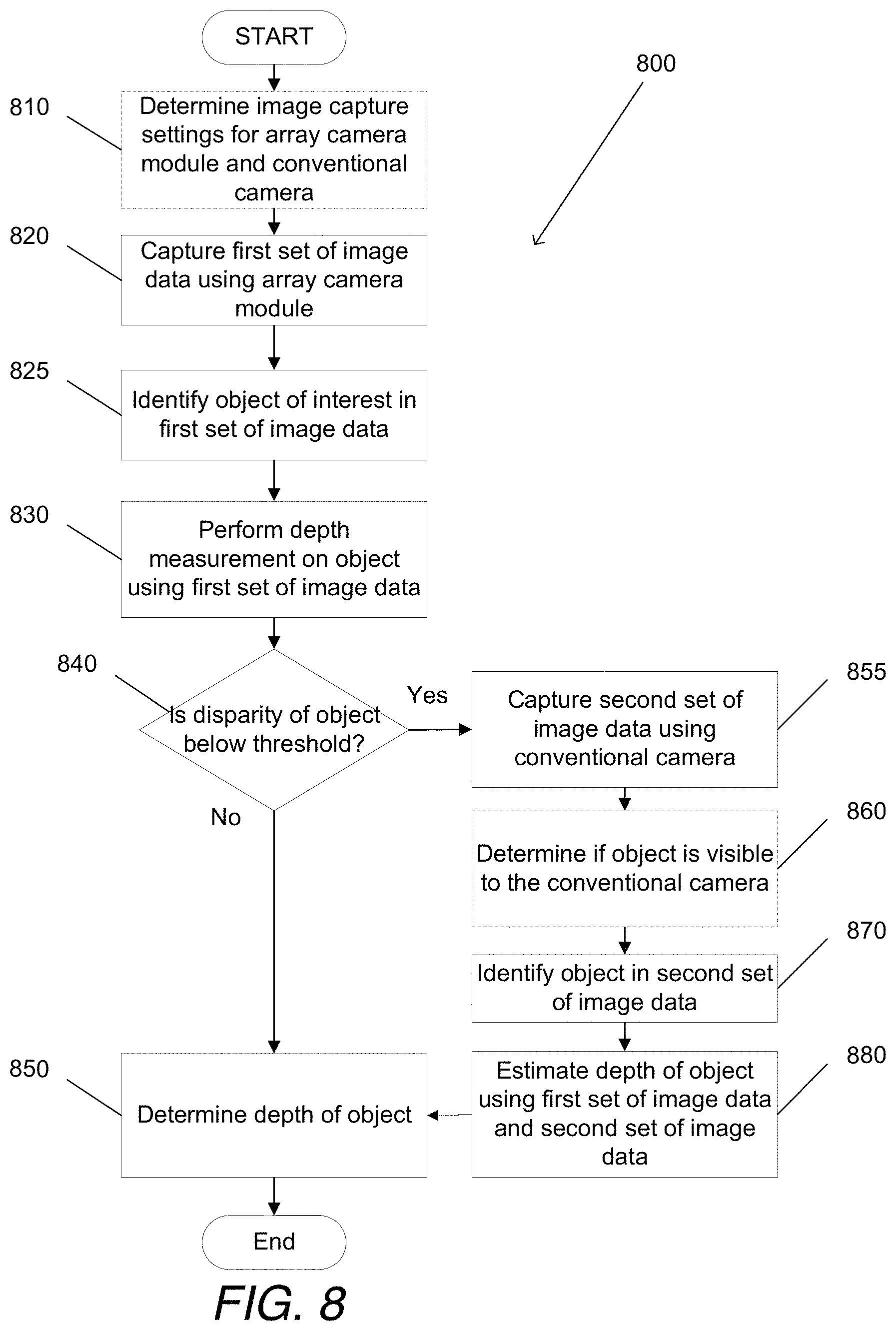
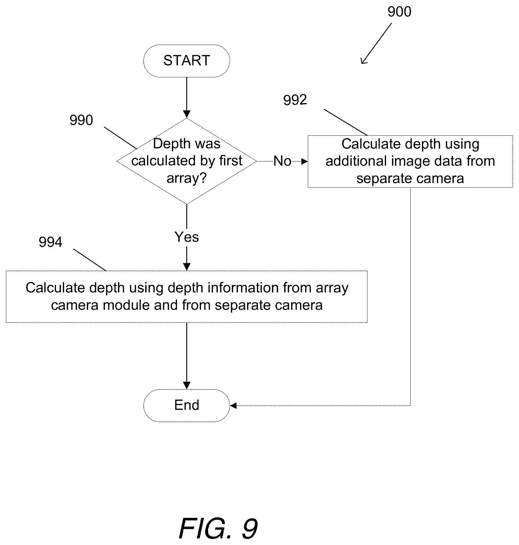
Systems with an array camera augmented with a conventional camera in accordance with embodiments of the invention are disclosed. In some embodiments, the array camera is used to capture a first set of image data of a scene and a conventional camera is used to capture a second set of image data for the scene. An object of interest is identified in the first set of image data. A first depth measurement for the object of interest is determined and compared to a predetermined threshold. If the first depth measurement is above the threshold, a second set of image data captured using the conventional camera is obtained. The object of interest is identified in the second set of image data and a second depth measurement for the object of interest is determined using at least a portion of the first set of image data and at least a portion of the second set of image data.
| Inventors: | Venkataraman; Kartik (San Jose, CA), Gallagher; Paul (San Jose, CA), Jain; Ankit K. (Mountain View, CA), Nisenzon; Semyon (Palo Alto, CA), Lelescu; Dan (Morgan Hill, CA), Ciurea; Florian (San Jose, CA), Molina; Gabriel (Grass Valley, CA) | ||||||||||
|---|---|---|---|---|---|---|---|---|---|---|---|
| Applicant: |
|
||||||||||
| Assignee: | FotoNation Limited (Galway,
IE) |
||||||||||
| Family ID: | 54070425 | ||||||||||
| Appl. No.: | 16/179,796 | ||||||||||
| Filed: | November 2, 2018 |
Prior Publication Data
| Document Identifier | Publication Date | |
|---|---|---|
| US 20190089947 A1 | Mar 21, 2019 | |
Related U.S. Patent Documents
| Application Number | Filing Date | Patent Number | Issue Date | ||
|---|---|---|---|---|---|
| 14724447 | May 28, 2015 | 10122993 | |||
| 14593369 | Apr 25, 2017 | 9633442 | |||
| 14216968 | Sep 6, 2016 | 9438888 | |||
| 61798673 | Mar 15, 2013 | ||||
| 62003015 | May 26, 2014 | ||||
| Current U.S. Class: | 1/1 |
| Current CPC Class: | H04N 13/243 (20180501); H04N 13/271 (20180501); G01P 3/38 (20130101); H04N 13/232 (20180501) |
| Current International Class: | H04N 13/271 (20180101); G01P 3/38 (20060101); H04N 13/243 (20180101); H04N 13/232 (20180101) |
References Cited [Referenced By]
U.S. Patent Documents
| 4124798 | November 1978 | Thompson |
| 4198646 | April 1980 | Alexander et al. |
| 4323925 | April 1982 | Abell et al. |
| 4460449 | July 1984 | Montalbano |
| 4467365 | August 1984 | Murayama et al. |
| 4652909 | March 1987 | Glenn |
| 4899060 | February 1990 | Lischke |
| 4962425 | October 1990 | Rea |
| 5005083 | April 1991 | Grage |
| 5070414 | December 1991 | Tsutsumi |
| 5144448 | September 1992 | Hornbaker et al. |
| 5157499 | October 1992 | Oguma et al. |
| 5325449 | June 1994 | Burt |
| 5327125 | July 1994 | Iwase et al. |
| 5463464 | October 1995 | Ladewski |
| 5488674 | January 1996 | Burt |
| 5629524 | May 1997 | Stettner et al. |
| 5638461 | June 1997 | Fridge |
| 5757425 | May 1998 | Barton et al. |
| 5793900 | August 1998 | Nourbakhsh et al. |
| 5801919 | September 1998 | Griencewic |
| 5808350 | September 1998 | Jack et al. |
| 5832312 | November 1998 | Rieger et al. |
| 5833507 | November 1998 | Woodgate et al. |
| 5880691 | March 1999 | Fossum et al. |
| 5911008 | June 1999 | Niikura et al. |
| 5933190 | August 1999 | Dierickx et al. |
| 5963664 | October 1999 | Kumar et al. |
| 5973844 | October 1999 | Burger |
| 6002743 | December 1999 | Telymonde |
| 6005607 | December 1999 | Uomori et al. |
| 6034690 | March 2000 | Gallery et al. |
| 6069351 | May 2000 | Mack |
| 6069365 | May 2000 | Chow et al. |
| 6095989 | August 2000 | Hay et al. |
| 6097394 | August 2000 | Levoy et al. |
| 6124974 | September 2000 | Burger |
| 6130786 | October 2000 | Osawa et al. |
| 6137100 | October 2000 | Fossum et al. |
| 6137535 | October 2000 | Meyers |
| 6141048 | October 2000 | Meyers |
| 6160909 | December 2000 | Melen |
| 6163414 | December 2000 | Kikuchi et al. |
| 6172352 | January 2001 | Liu et al. |
| 6175379 | January 2001 | Uomori et al. |
| 6205241 | March 2001 | Melen |
| 6239909 | May 2001 | Hayashi et al. |
| 6292713 | September 2001 | Jouppi et al. |
| 6340994 | January 2002 | Margulis et al. |
| 6358862 | March 2002 | Ireland et al. |
| 6373518 | April 2002 | Sogawa |
| 6419638 | July 2002 | Hay et al. |
| 6443579 | September 2002 | Myers |
| 6476805 | November 2002 | Shum et al. |
| 6477260 | November 2002 | Shimomura |
| 6502097 | December 2002 | Chan et al. |
| 6525302 | February 2003 | Dowski, Jr. et al. |
| 6552742 | April 2003 | Seta |
| 6563537 | May 2003 | Kawamura et al. |
| 6571466 | June 2003 | Glenn et al. |
| 6603513 | August 2003 | Berezin |
| 6611289 | August 2003 | Yu |
| 6627896 | September 2003 | Hashimoto et al. |
| 6628330 | September 2003 | Lin |
| 6628845 | September 2003 | Stone et al. |
| 6635941 | October 2003 | Suda |
| 6639596 | October 2003 | Shum et al. |
| 6647142 | November 2003 | Beardsley |
| 6657218 | December 2003 | Noda |
| 6671399 | December 2003 | Berestov |
| 6674892 | January 2004 | Melen |
| 6750904 | June 2004 | Lambert |
| 6765617 | July 2004 | Tangen et al. |
| 6771833 | August 2004 | Edgar |
| 6774941 | August 2004 | Boisvert et al. |
| 6788338 | September 2004 | Dinev |
| 6795253 | September 2004 | Shinohara |
| 6801653 | October 2004 | Wu et al. |
| 6819328 | November 2004 | Moriwaki et al. |
| 6819358 | November 2004 | Kagle et al. |
| 6833863 | December 2004 | Clemens |
| 6879735 | April 2005 | Portniaguine et al. |
| 6897454 | May 2005 | Sasaki et al. |
| 6903770 | June 2005 | Kobayashi et al. |
| 6909121 | June 2005 | Nishikawa |
| 6917702 | July 2005 | Beardsley |
| 6927922 | August 2005 | George |
| 6958862 | October 2005 | Joseph |
| 6985175 | January 2006 | Iwai et al. |
| 7015954 | March 2006 | Foote et al. |
| 7085409 | August 2006 | Sawhney |
| 7161614 | January 2007 | Yamashita et al. |
| 7199348 | April 2007 | Olsen et al. |
| 7206449 | April 2007 | Raskar et al. |
| 7215364 | May 2007 | Wachtel et al. |
| 7235785 | June 2007 | Hornback et al. |
| 7245761 | July 2007 | Swaminathan et al. |
| 7262799 | August 2007 | Suda |
| 7292735 | November 2007 | Blake et al. |
| 7295697 | November 2007 | Satoh |
| 7333651 | February 2008 | Kim et al. |
| 7369165 | May 2008 | Bosco et al. |
| 7391572 | June 2008 | Jacobowitz et al. |
| 7408725 | August 2008 | Sato |
| 7425984 | September 2008 | Chen |
| 7430312 | September 2008 | Gu |
| 7471765 | December 2008 | Jaffray et al. |
| 7496293 | February 2009 | Shamir et al. |
| 7564019 | July 2009 | Olsen |
| 7599547 | October 2009 | Sun et al. |
| 7606484 | October 2009 | Richards et al. |
| 7620265 | November 2009 | Wolff |
| 7633511 | December 2009 | Shum et al. |
| 7639435 | December 2009 | Chiang et al. |
| 7646549 | January 2010 | Zalevsky et al. |
| 7657090 | February 2010 | Omatsu et al. |
| 7667824 | February 2010 | Moran |
| 7675080 | March 2010 | Boettiger |
| 7675681 | March 2010 | Tomikawa et al. |
| 7706634 | April 2010 | Schmitt et al. |
| 7723662 | May 2010 | Levoy et al. |
| 7738013 | June 2010 | Galambos et al. |
| 7741620 | June 2010 | Doering et al. |
| 7782364 | August 2010 | Smith |
| 7826153 | November 2010 | Hong |
| 7840067 | November 2010 | Shen et al. |
| 7912673 | March 2011 | Hebert et al. |
| 7924321 | April 2011 | Nayar et al. |
| 7956871 | June 2011 | Fainstain et al. |
| 7965314 | June 2011 | Miller et al. |
| 7973834 | July 2011 | Yang |
| 7986018 | July 2011 | Rennie |
| 7990447 | August 2011 | Honda et al. |
| 8000498 | August 2011 | Shih et al. |
| 8013904 | September 2011 | Tan et al. |
| 8027531 | September 2011 | Wilburn et al. |
| 8044994 | October 2011 | Vetro et al. |
| 8055466 | November 2011 | Bryll |
| 8077245 | December 2011 | Adamo et al. |
| 8089515 | January 2012 | Chebil et al. |
| 8098297 | January 2012 | Crisan et al. |
| 8098304 | January 2012 | Pinto et al. |
| 8106949 | January 2012 | Tan et al. |
| 8111910 | February 2012 | Tanaka |
| 8126279 | February 2012 | Marcellin et al. |
| 8130120 | March 2012 | Kawabata et al. |
| 8131097 | March 2012 | Lelescu et al. |
| 8149323 | April 2012 | Li |
| 8164629 | April 2012 | Zhang |
| 8169486 | May 2012 | Corcoran et al. |
| 8180145 | May 2012 | Wu et al. |
| 8189065 | May 2012 | Georgiev et al. |
| 8189089 | May 2012 | Georgiev et al. |
| 8194296 | June 2012 | Compton |
| 8212914 | July 2012 | Chiu |
| 8213711 | July 2012 | Tam |
| 8231814 | July 2012 | Duparre |
| 8242426 | August 2012 | Ward et al. |
| 8244027 | August 2012 | Takahashi |
| 8244058 | August 2012 | Intwala et al. |
| 8254668 | August 2012 | Mashitani et al. |
| 8279325 | October 2012 | Pitts et al. |
| 8280194 | October 2012 | Wong et al. |
| 8284240 | October 2012 | Saint-Pierre et al. |
| 8289409 | October 2012 | Chang |
| 8289440 | October 2012 | Pitts et al. |
| 8290358 | October 2012 | Georgiev |
| 8294099 | October 2012 | Blackwell, Jr. |
| 8294754 | October 2012 | Jung et al. |
| 8300085 | October 2012 | Yang et al. |
| 8305456 | November 2012 | McMahon |
| 8315476 | November 2012 | Georgiev et al. |
| 8345144 | January 2013 | Georgiev et al. |
| 8360574 | January 2013 | Ishak et al. |
| 8400555 | March 2013 | Georgiev |
| 8406562 | March 2013 | Bassi et al. |
| 8411146 | April 2013 | Twede |
| 8416282 | April 2013 | Lablans |
| 8446492 | May 2013 | Nakano et al. |
| 8456517 | June 2013 | Mor et al. |
| 8493496 | July 2013 | Freedman et al. |
| 8514291 | August 2013 | Chang |
| 8514491 | August 2013 | Duparre |
| 8541730 | September 2013 | Inuiya |
| 8542933 | September 2013 | Venkataraman et al. |
| 8553093 | October 2013 | Wong et al. |
| 8559705 | October 2013 | Ng |
| 8559756 | October 2013 | Georgiev et al. |
| 8565547 | October 2013 | Strandemar |
| 8576302 | November 2013 | Yoshikawa |
| 8577183 | November 2013 | Robinson |
| 8581995 | November 2013 | Lin et al. |
| 8619082 | December 2013 | Ciurea et al. |
| 8648918 | February 2014 | Kauker et al. |
| 8655052 | February 2014 | Spooner et al. |
| 8682107 | March 2014 | Yoon et al. |
| 8687087 | April 2014 | Pertsel et al. |
| 8692893 | April 2014 | McMahon |
| 8754941 | June 2014 | Sarwari et al. |
| 8773536 | July 2014 | Zhang |
| 8780113 | July 2014 | Ciurea et al. |
| 8804255 | August 2014 | Duparre |
| 8830375 | September 2014 | Ludwig |
| 8831367 | September 2014 | Venkataraman et al. |
| 8831377 | September 2014 | Pitts et al. |
| 8836793 | September 2014 | Kriesel et al. |
| 8842201 | September 2014 | Tajiri |
| 8854462 | October 2014 | Herbin et al. |
| 8861089 | October 2014 | Duparre |
| 8866912 | October 2014 | Mullis |
| 8866920 | October 2014 | Venkataraman et al. |
| 8866951 | October 2014 | Keelan |
| 8878950 | November 2014 | Lelescu et al. |
| 8885059 | November 2014 | Venkataraman et al. |
| 8885922 | November 2014 | Ito et al. |
| 8896594 | November 2014 | Xiong et al. |
| 8896719 | November 2014 | Venkataraman et al. |
| 8902321 | December 2014 | Venkataraman et al. |
| 8928793 | January 2015 | McMahon |
| 8977038 | March 2015 | Tian et al. |
| 9001226 | April 2015 | Ng et al. |
| 9019426 | April 2015 | Han et al. |
| 9025894 | May 2015 | Venkataraman |
| 9025895 | May 2015 | Venkataraman |
| 9030528 | May 2015 | Pesach et al. |
| 9031335 | May 2015 | Venkataraman |
| 9031342 | May 2015 | Venkataraman |
| 9031343 | May 2015 | Venkataraman |
| 9036928 | May 2015 | Venkataraman |
| 9036931 | May 2015 | Venkataraman et al. |
| 9041823 | May 2015 | Venkataraman et al. |
| 9041824 | May 2015 | Lelescu et al. |
| 9041829 | May 2015 | Venkataraman et al. |
| 9042667 | May 2015 | Venkataraman et al. |
| 9047684 | June 2015 | Lelescu et al. |
| 9049367 | June 2015 | Venkataraman et al. |
| 9055233 | June 2015 | Venkataraman et al. |
| 9060120 | June 2015 | Venkataraman et al. |
| 9060124 | June 2015 | Venkataraman et al. |
| 9077893 | July 2015 | Venkataraman et al. |
| 9094661 | July 2015 | Venkataraman et al. |
| 9100586 | August 2015 | McMahon et al. |
| 9100635 | August 2015 | Duparre et al. |
| 9123117 | September 2015 | Ciurea et al. |
| 9123118 | September 2015 | Ciurea et al. |
| 9124815 | September 2015 | Venkataraman et al. |
| 9124831 | September 2015 | Mullis |
| 9124864 | September 2015 | Mullis |
| 9128228 | September 2015 | Duparre |
| 9129183 | September 2015 | Venkataraman et al. |
| 9129377 | September 2015 | Ciurea et al. |
| 9143711 | September 2015 | McMahon |
| 9147254 | September 2015 | Ciurea et al. |
| 9185276 | November 2015 | Rodda et al. |
| 9188765 | November 2015 | Venkataraman et al. |
| 9191580 | November 2015 | Venkataraman et al. |
| 9197821 | November 2015 | McMahon |
| 9210392 | December 2015 | Nisenzon et al. |
| 9214013 | December 2015 | Venkataraman et al. |
| 9235898 | January 2016 | Venkataraman et al. |
| 9235900 | January 2016 | Ciurea et al. |
| 9240049 | January 2016 | Ciurea et al. |
| 9253380 | February 2016 | Venkataraman et al. |
| 9253397 | February 2016 | Lee et al. |
| 9256974 | February 2016 | Hines |
| 9264592 | February 2016 | Rodda et al. |
| 9264610 | February 2016 | Duparre |
| 9361662 | June 2016 | Lelescu et al. |
| 9374512 | June 2016 | Venkataraman et al. |
| 9412206 | August 2016 | McMahon et al. |
| 9413953 | August 2016 | Maeda |
| 9426343 | August 2016 | Rodda et al. |
| 9426361 | August 2016 | Venkataraman et al. |
| 9438888 | September 2016 | Venkataraman et al. |
| 9445003 | September 2016 | Lelescu et al. |
| 9456134 | September 2016 | Venkataraman et al. |
| 9456196 | September 2016 | Kim et al. |
| 9462164 | October 2016 | Venkataraman et al. |
| 9485496 | November 2016 | Venkataraman et al. |
| 9497370 | November 2016 | Venkataraman et al. |
| 9497429 | November 2016 | Mullis et al. |
| 9516222 | December 2016 | Duparre et al. |
| 9519972 | December 2016 | Venkataraman et al. |
| 9521319 | December 2016 | Rodda et al. |
| 9521416 | December 2016 | McMahon et al. |
| 9536166 | January 2017 | Venkataraman et al. |
| 9576369 | February 2017 | Venkataraman et al. |
| 9578237 | February 2017 | Duparre et al. |
| 9578259 | February 2017 | Molina |
| 9602805 | March 2017 | Venkataraman et al. |
| 9633442 | April 2017 | Venkataraman et al. |
| 9635274 | April 2017 | Lin et al. |
| 9638883 | May 2017 | Duparre |
| 9661310 | May 2017 | Deng et al. |
| 9706132 | July 2017 | Nisenzon et al. |
| 9712759 | July 2017 | Venkataraman et al. |
| 9733486 | August 2017 | Lelescu et al. |
| 9741118 | August 2017 | Mullis |
| 9743051 | August 2017 | Venkataraman et al. |
| 9749547 | August 2017 | Venkataraman et al. |
| 9749568 | August 2017 | McMahon |
| 9754422 | September 2017 | McMahon et al. |
| 9766380 | September 2017 | Duparre et al. |
| 9769365 | September 2017 | Jannard |
| 9774789 | September 2017 | Ciurea et al. |
| 9774831 | September 2017 | Venkataraman et al. |
| 9787911 | October 2017 | McMahon et al. |
| 9794476 | October 2017 | Nayar et al. |
| 9800856 | October 2017 | Venkataraman et al. |
| 9800859 | October 2017 | Venkataraman et al. |
| 9807382 | October 2017 | Duparre et al. |
| 9811753 | November 2017 | Venkataraman et al. |
| 9813616 | November 2017 | Lelescu et al. |
| 9813617 | November 2017 | Venkataraman et al. |
| 9858673 | January 2018 | Ciurea et al. |
| 9864921 | January 2018 | Venkataraman et al. |
| 9888194 | February 2018 | Duparre |
| 9898856 | February 2018 | Yang et al. |
| 9917998 | March 2018 | Venkataraman et al. |
| 9924092 | March 2018 | Rodda et al. |
| 9936148 | April 2018 | McMahon |
| 9955070 | April 2018 | Lelescu et al. |
| 9986224 | May 2018 | Mullis |
| 10009538 | June 2018 | Venkataraman et al. |
| 10019816 | July 2018 | Venkataraman et al. |
| 10027901 | July 2018 | Venkataraman et al. |
| 10089740 | October 2018 | Srikanth et al. |
| 10091405 | October 2018 | Molina |
| 10119808 | November 2018 | Venkataraman et al. |
| 10122993 | November 2018 | Venkataraman et al. |
| 10127682 | November 2018 | Mullis |
| 10142560 | November 2018 | Venkataraman et al. |
| 10182216 | January 2019 | Mullis et al. |
| 10225543 | March 2019 | Mullis |
| 10261219 | April 2019 | Duparre et al. |
| 10306120 | May 2019 | Duparre |
| 10455218 | October 2019 | Venkataraman et al. |
| 2001/0005225 | June 2001 | Clark et al. |
| 2001/0019621 | September 2001 | Hanna et al. |
| 2001/0028038 | October 2001 | Hamaguchi et al. |
| 2001/0038387 | November 2001 | Tomooka et al. |
| 2002/0012056 | January 2002 | Trevino |
| 2002/0015536 | February 2002 | Warren |
| 2002/0027608 | March 2002 | Johnson et al. |
| 2002/0028014 | March 2002 | Ono |
| 2002/0039438 | April 2002 | Mori et al. |
| 2002/0057845 | May 2002 | Fossum |
| 2002/0061131 | May 2002 | Sawhney et al. |
| 2002/0063807 | May 2002 | Margulis |
| 2002/0075450 | June 2002 | Aratani |
| 2002/0087403 | July 2002 | Meyers et al. |
| 2002/0089596 | July 2002 | Suda |
| 2002/0094027 | July 2002 | Sato et al. |
| 2002/0101528 | August 2002 | Lee |
| 2002/0113867 | August 2002 | Takigawa et al. |
| 2002/0113888 | August 2002 | Sonoda et al. |
| 2002/0118113 | August 2002 | Oku et al. |
| 2002/0120634 | August 2002 | Min et al. |
| 2002/0122113 | September 2002 | Foote et al. |
| 2002/0163054 | November 2002 | Suda et al. |
| 2002/0167537 | November 2002 | Trajkovic |
| 2002/0177054 | November 2002 | Saitoh et al. |
| 2002/0190991 | December 2002 | Efran et al. |
| 2002/0195548 | December 2002 | Dowski, Jr. et al. |
| 2003/0025227 | February 2003 | Daniell |
| 2003/0086079 | May 2003 | Barth et al. |
| 2003/0124763 | July 2003 | Fan et al. |
| 2003/0140347 | July 2003 | Varsa |
| 2003/0156189 | August 2003 | Utsumi et al. |
| 2003/0179418 | September 2003 | Wengender et al. |
| 2003/0188659 | October 2003 | Merry et al. |
| 2003/0190072 | October 2003 | Adkins et al. |
| 2003/0198377 | October 2003 | Ng |
| 2003/0211405 | November 2003 | Venkataraman |
| 2003/0231179 | December 2003 | Suzuki |
| 2004/0003409 | January 2004 | Berstis |
| 2004/0008271 | January 2004 | Hagimori et al. |
| 2004/0012689 | January 2004 | Tinnerino |
| 2004/0027358 | February 2004 | Nakao |
| 2004/0047274 | March 2004 | Amanai |
| 2004/0050104 | March 2004 | Ghosh et al. |
| 2004/0056966 | March 2004 | Schechner et al. |
| 2004/0061787 | April 2004 | Liu et al. |
| 2004/0066454 | April 2004 | Otani et al. |
| 2004/0071367 | April 2004 | Irani et al. |
| 2004/0075654 | April 2004 | Hsiao et al. |
| 2004/0096119 | May 2004 | Williams |
| 2004/0100570 | May 2004 | Shizukuishi |
| 2004/0105021 | June 2004 | Hu et al. |
| 2004/0114807 | June 2004 | Lelescu et al. |
| 2004/0141659 | July 2004 | Zhang |
| 2004/0151401 | August 2004 | Sawhney et al. |
| 2004/0165090 | August 2004 | Ning |
| 2004/0169617 | September 2004 | Yelton et al. |
| 2004/0170340 | September 2004 | Tipping et al. |
| 2004/0174439 | September 2004 | Upton |
| 2004/0179008 | September 2004 | Gordon et al. |
| 2004/0179834 | September 2004 | Szajewski |
| 2004/0196379 | October 2004 | Chen et al. |
| 2004/0207600 | October 2004 | Zhang et al. |
| 2004/0207836 | October 2004 | Chhibber et al. |
| 2004/0213449 | October 2004 | Safaee-Rad et al. |
| 2004/0218809 | November 2004 | Blake et al. |
| 2004/0234873 | November 2004 | Venkataraman |
| 2004/0239782 | December 2004 | Equitz et al. |
| 2004/0239885 | December 2004 | Jaynes et al. |
| 2004/0240052 | December 2004 | Minefuji et al. |
| 2004/0251509 | December 2004 | Choi |
| 2004/0264806 | December 2004 | Herley |
| 2005/0006477 | January 2005 | Patel |
| 2005/0007461 | January 2005 | Chou et al. |
| 2005/0009313 | January 2005 | Suzuki et al. |
| 2005/0010621 | January 2005 | Pinto et al. |
| 2005/0012035 | January 2005 | Miller |
| 2005/0036778 | February 2005 | DeMonte |
| 2005/0047678 | March 2005 | Jones et al. |
| 2005/0048690 | March 2005 | Yamamoto |
| 2005/0068436 | March 2005 | Fraenkel et al. |
| 2005/0083531 | April 2005 | Millerd et al. |
| 2005/0084179 | April 2005 | Hanna et al. |
| 2005/0128509 | June 2005 | Tokkonen et al. |
| 2005/0128595 | June 2005 | Shimizu |
| 2005/0132098 | June 2005 | Sonoda et al. |
| 2005/0134698 | June 2005 | Schroeder |
| 2005/0134699 | June 2005 | Nagashima |
| 2005/0134712 | June 2005 | Gruhlke et al. |
| 2005/0147277 | July 2005 | Higaki et al. |
| 2005/0151759 | July 2005 | Gonzalez-Banos et al. |
| 2005/0168924 | August 2005 | Wu et al. |
| 2005/0175257 | August 2005 | Kuroki |
| 2005/0185711 | August 2005 | Pfister et al. |
| 2005/0205785 | September 2005 | Hornback et al. |
| 2005/0219264 | October 2005 | Shum et al. |
| 2005/0219363 | October 2005 | Kohler et al. |
| 2005/0224843 | October 2005 | Boemler |
| 2005/0225654 | October 2005 | Feldman et al. |
| 2005/0265633 | December 2005 | Piacentino et al. |
| 2005/0275946 | December 2005 | Choo et al. |
| 2005/0286612 | December 2005 | Takanashi |
| 2005/0286756 | December 2005 | Hong et al. |
| 2006/0002635 | January 2006 | Nestares et al. |
| 2006/0007331 | January 2006 | Izumi et al. |
| 2006/0013318 | January 2006 | Webb et al. |
| 2006/0018509 | January 2006 | Miyoshi |
| 2006/0023197 | February 2006 | Joel |
| 2006/0023314 | February 2006 | Boettiger et al. |
| 2006/0028476 | February 2006 | Sobel et al. |
| 2006/0029270 | February 2006 | Berestov et al. |
| 2006/0029271 | February 2006 | Miyoshi et al. |
| 2006/0033005 | February 2006 | Jerdev et al. |
| 2006/0034003 | February 2006 | Zalevsky |
| 2006/0034531 | February 2006 | Poon et al. |
| 2006/0035415 | February 2006 | Wood |
| 2006/0038891 | February 2006 | Okutomi et al. |
| 2006/0039611 | February 2006 | Rother et al. |
| 2006/0046204 | March 2006 | Ono et al. |
| 2006/0049930 | March 2006 | Zruya et al. |
| 2006/0050980 | March 2006 | Kohashi et al. |
| 2006/0054780 | March 2006 | Garrood et al. |
| 2006/0054782 | March 2006 | Olsen et al. |
| 2006/0055811 | March 2006 | Frtiz et al. |
| 2006/0069478 | March 2006 | Iwama |
| 2006/0072029 | April 2006 | Miyatake et al. |
| 2006/0087747 | April 2006 | Ohzawa et al. |
| 2006/0098888 | May 2006 | Morishita |
| 2006/0103754 | May 2006 | Wenstrand et al. |
| 2006/0125936 | June 2006 | Gruhike et al. |
| 2006/0138322 | June 2006 | Costello et al. |
| 2006/0152803 | July 2006 | Provitola |
| 2006/0157640 | July 2006 | Perlman et al. |
| 2006/0159369 | July 2006 | Young |
| 2006/0176566 | August 2006 | Boettiger et al. |
| 2006/0187322 | August 2006 | Janson, Jr. et al. |
| 2006/0187338 | August 2006 | May et al. |
| 2006/0197937 | September 2006 | Bamji et al. |
| 2006/0203100 | September 2006 | Ajito et al. |
| 2006/0203113 | September 2006 | Wada et al. |
| 2006/0210146 | September 2006 | Gu |
| 2006/0210186 | September 2006 | Berkner |
| 2006/0214085 | September 2006 | Olsen |
| 2006/0221250 | October 2006 | Rossbach et al. |
| 2006/0239549 | October 2006 | Kelly et al. |
| 2006/0243889 | November 2006 | Farnworth et al. |
| 2006/0251410 | November 2006 | Trutna |
| 2006/0274174 | December 2006 | Tewinkle |
| 2006/0278948 | December 2006 | Yamaguchi et al. |
| 2006/0279648 | December 2006 | Senba et al. |
| 2006/0289772 | December 2006 | Johnson et al. |
| 2007/0002159 | January 2007 | Olsen et al. |
| 2007/0008575 | January 2007 | Yu et al. |
| 2007/0009150 | January 2007 | Suwa |
| 2007/0024614 | February 2007 | Tam |
| 2007/0030356 | February 2007 | Yea et al. |
| 2007/0035707 | February 2007 | Margulis |
| 2007/0036427 | February 2007 | Nakamura et al. |
| 2007/0040828 | February 2007 | Zalevsky et al. |
| 2007/0040922 | February 2007 | McKee et al. |
| 2007/0041391 | February 2007 | Lin et al. |
| 2007/0052825 | March 2007 | Cho |
| 2007/0083114 | April 2007 | Yang et al. |
| 2007/0085917 | April 2007 | Kobayashi |
| 2007/0092245 | April 2007 | Bazakos et al. |
| 2007/0102622 | May 2007 | Olsen et al. |
| 2007/0126898 | June 2007 | Feldman et al. |
| 2007/0127831 | June 2007 | Venkataraman |
| 2007/0139333 | June 2007 | Sato et al. |
| 2007/0140685 | June 2007 | Wu |
| 2007/0146503 | June 2007 | Shiraki |
| 2007/0146511 | June 2007 | Kinoshita et al. |
| 2007/0153335 | July 2007 | Hosaka |
| 2007/0158427 | July 2007 | Zhu et al. |
| 2007/0159541 | July 2007 | Sparks et al. |
| 2007/0160310 | July 2007 | Tanida et al. |
| 2007/0165931 | July 2007 | Higaki |
| 2007/0166447 | July 2007 | U r-Rehman et al. |
| 2007/0171290 | July 2007 | Kroger |
| 2007/0177004 | August 2007 | Kolehmainen et al. |
| 2007/0182843 | August 2007 | Shimamura et al. |
| 2007/0201859 | August 2007 | Sarrat |
| 2007/0206241 | September 2007 | Smith et al. |
| 2007/0211164 | September 2007 | Olsen et al. |
| 2007/0216765 | September 2007 | Wong et al. |
| 2007/0225600 | September 2007 | Weibrecht et al. |
| 2007/0228256 | October 2007 | Mentzer |
| 2007/0236595 | October 2007 | Pan et al. |
| 2007/0242141 | October 2007 | Ciurea |
| 2007/0247517 | October 2007 | Zhang et al. |
| 2007/0257184 | November 2007 | Olsen et al. |
| 2007/0258006 | November 2007 | Olsen et al. |
| 2007/0258706 | November 2007 | Raskar et al. |
| 2007/0263113 | November 2007 | Baek et al. |
| 2007/0263114 | November 2007 | Gurevich et al. |
| 2007/0268374 | November 2007 | Robinson |
| 2007/0296721 | December 2007 | Chang et al. |
| 2007/0296832 | December 2007 | Ota et al. |
| 2007/0296835 | December 2007 | Olsen |
| 2007/0296847 | December 2007 | Chang et al. |
| 2007/0297696 | December 2007 | Hamza |
| 2008/0006859 | January 2008 | Mionetto et al. |
| 2008/0019611 | January 2008 | Larkin et al. |
| 2008/0024683 | January 2008 | Damera-Venkata et al. |
| 2008/0025649 | January 2008 | Liu et al. |
| 2008/0030592 | February 2008 | Border et al. |
| 2008/0030597 | February 2008 | Olsen et al. |
| 2008/0043095 | February 2008 | Vetro et al. |
| 2008/0043096 | February 2008 | Vetro et al. |
| 2008/0054518 | March 2008 | Ra et al. |
| 2008/0056302 | March 2008 | Erdal et al. |
| 2008/0062164 | March 2008 | Bassi et al. |
| 2008/0079805 | April 2008 | Takagi et al. |
| 2008/0080028 | April 2008 | Bakin et al. |
| 2008/0084486 | April 2008 | Enge et al. |
| 2008/0088793 | April 2008 | Sverdrup et al. |
| 2008/0095523 | April 2008 | Schilling-Benz et al. |
| 2008/0099804 | May 2008 | Venezia et al. |
| 2008/0106620 | May 2008 | Sawachi |
| 2008/0112059 | May 2008 | Choi et al. |
| 2008/0112635 | May 2008 | Kondo et al. |
| 2008/0117289 | May 2008 | Schowengerdt et al. |
| 2008/0118241 | May 2008 | Tekolste et al. |
| 2008/0131019 | June 2008 | Ng |
| 2008/0131107 | June 2008 | Ueno |
| 2008/0151097 | June 2008 | Chen et al. |
| 2008/0152215 | June 2008 | Horie et al. |
| 2008/0152296 | June 2008 | Oh et al. |
| 2008/0156991 | July 2008 | Hu et al. |
| 2008/0158259 | July 2008 | Kempf et al. |
| 2008/0158375 | July 2008 | Kakkori et al. |
| 2008/0158698 | July 2008 | Chang et al. |
| 2008/0165257 | July 2008 | Boettiger |
| 2008/0174670 | July 2008 | Olsen et al. |
| 2008/0187305 | August 2008 | Raskar et al. |
| 2008/0193026 | August 2008 | Horie et al. |
| 2008/0211737 | September 2008 | Kim et al. |
| 2008/0218610 | September 2008 | Chapman et al. |
| 2008/0218611 | September 2008 | Parulski et al. |
| 2008/0218612 | September 2008 | Border et al. |
| 2008/0218613 | September 2008 | Janson et al. |
| 2008/0219654 | September 2008 | Border et al. |
| 2008/0239116 | October 2008 | Smith |
| 2008/0240598 | October 2008 | Hasegawa |
| 2008/0247638 | October 2008 | Tanida et al. |
| 2008/0247653 | October 2008 | Moussavi et al. |
| 2008/0272416 | November 2008 | Yun |
| 2008/0273751 | November 2008 | Yuan et al. |
| 2008/0278591 | November 2008 | Barna et al. |
| 2008/0278610 | November 2008 | Boettiger |
| 2008/0284880 | November 2008 | Numata |
| 2008/0291295 | November 2008 | Kato et al. |
| 2008/0298674 | December 2008 | Baker et al. |
| 2008/0310501 | December 2008 | Ward et al. |
| 2009/0027543 | January 2009 | Kanehiro |
| 2009/0050946 | February 2009 | Duparre et al. |
| 2009/0052743 | February 2009 | Techmer |
| 2009/0060281 | March 2009 | Tanida et al. |
| 2009/0066693 | March 2009 | Carson |
| 2009/0079862 | March 2009 | Subbotin |
| 2009/0086074 | April 2009 | Li et al. |
| 2009/0091645 | April 2009 | Trimeche et al. |
| 2009/0091806 | April 2009 | Inuiya |
| 2009/0092363 | April 2009 | Daum et al. |
| 2009/0096050 | April 2009 | Park |
| 2009/0102956 | April 2009 | Georgiev |
| 2009/0103792 | April 2009 | Rahn et al. |
| 2009/0109306 | April 2009 | Shan |
| 2009/0127430 | May 2009 | Hirasawa et al. |
| 2009/0128644 | May 2009 | Camp et al. |
| 2009/0128833 | May 2009 | Yahav |
| 2009/0129667 | May 2009 | Ho et al. |
| 2009/0140131 | June 2009 | Utagawa et al. |
| 2009/0141933 | June 2009 | Wagg |
| 2009/0147919 | June 2009 | Goto et al. |
| 2009/0152664 | June 2009 | Klem et al. |
| 2009/0167922 | July 2009 | Perlman et al. |
| 2009/0167923 | July 2009 | Safaee-Rad et al. |
| 2009/0167934 | July 2009 | Gupta |
| 2009/0175349 | July 2009 | Ye et al. |
| 2009/0179142 | July 2009 | Duparre et al. |
| 2009/0180021 | July 2009 | Kikuchi et al. |
| 2009/0200622 | August 2009 | Tai et al. |
| 2009/0201371 | August 2009 | Matsuda et al. |
| 2009/0207235 | August 2009 | Francini et al. |
| 2009/0219435 | September 2009 | Yuan et al. |
| 2009/0225203 | September 2009 | Tanida et al. |
| 2009/0237520 | September 2009 | Kaneko et al. |
| 2009/0245573 | October 2009 | Saptharishi et al. |
| 2009/0256947 | October 2009 | Ciurea et al. |
| 2009/0263017 | October 2009 | Tanbakuchi |
| 2009/0268192 | October 2009 | Koenck et al. |
| 2009/0268970 | October 2009 | Babacan et al. |
| 2009/0268983 | October 2009 | Stone et al. |
| 2009/0273663 | November 2009 | Yoshida et al. |
| 2009/0274387 | November 2009 | Jin |
| 2009/0279800 | November 2009 | Uetani et al. |
| 2009/0284651 | November 2009 | Srinivasan |
| 2009/0290811 | November 2009 | Imai |
| 2009/0297056 | December 2009 | Lelescu et al. |
| 2009/0302205 | December 2009 | Olsen et al. |
| 2009/0317061 | December 2009 | Jung et al. |
| 2009/0322876 | December 2009 | Lee et al. |
| 2009/0323195 | December 2009 | Hembree et al. |
| 2009/0323206 | December 2009 | Oliver et al. |
| 2009/0324118 | December 2009 | Maslov et al. |
| 2010/0002126 | January 2010 | Wenstrand et al. |
| 2010/0002313 | January 2010 | Duparre et al. |
| 2010/0002314 | January 2010 | Duparre |
| 2010/0007714 | January 2010 | Kim et al. |
| 2010/0013927 | January 2010 | Nixon |
| 2010/0044815 | February 2010 | Chang et al. |
| 2010/0045809 | February 2010 | Packard |
| 2010/0053342 | March 2010 | Hwang et al. |
| 2010/0053415 | March 2010 | Yun |
| 2010/0053600 | March 2010 | Tanida et al. |
| 2010/0060746 | March 2010 | Olsen et al. |
| 2010/0073463 | March 2010 | Momonoi et al. |
| 2010/0074532 | March 2010 | Gordon et al. |
| 2010/0085351 | April 2010 | Deb et al. |
| 2010/0085425 | April 2010 | Tan |
| 2010/0086227 | April 2010 | Sun et al. |
| 2010/0091389 | April 2010 | Henriksen et al. |
| 2010/0097491 | April 2010 | Farina et al. |
| 2010/0103175 | April 2010 | Okutomi et al. |
| 2010/0103259 | April 2010 | Tanida et al. |
| 2010/0103308 | April 2010 | Butterfield et al. |
| 2010/0111444 | May 2010 | Coffman |
| 2010/0118127 | May 2010 | Nam et al. |
| 2010/0128145 | May 2010 | Pitts et al. |
| 2010/0129048 | May 2010 | Pitts et al. |
| 2010/0133230 | June 2010 | Henriksen et al. |
| 2010/0133418 | June 2010 | Sargent et al. |
| 2010/0141802 | June 2010 | Knight et al. |
| 2010/0142828 | June 2010 | Chang et al. |
| 2010/0142839 | June 2010 | Lakus-Becker |
| 2010/0157073 | June 2010 | Kondo et al. |
| 2010/0165152 | July 2010 | Lim |
| 2010/0166410 | July 2010 | Chang et al. |
| 2010/0171866 | July 2010 | Brady et al. |
| 2010/0177411 | July 2010 | Hegde et al. |
| 2010/0182406 | July 2010 | Benitez |
| 2010/0194860 | August 2010 | Mentz et al. |
| 2010/0194901 | August 2010 | van Hoorebeke et al. |
| 2010/0195716 | August 2010 | Gunnewiek et al. |
| 2010/0201809 | August 2010 | Oyama et al. |
| 2010/0201834 | August 2010 | Maruyama et al. |
| 2010/0202054 | August 2010 | Niederer |
| 2010/0202683 | August 2010 | Robinson |
| 2010/0208100 | August 2010 | Olsen et al. |
| 2010/0220212 | September 2010 | Perlman et al. |
| 2010/0223237 | September 2010 | Mishra et al. |
| 2010/0225740 | September 2010 | Jung et al. |
| 2010/0231285 | September 2010 | Boomer et al. |
| 2010/0238327 | September 2010 | Griffith et al. |
| 2010/0244165 | September 2010 | Lake et al. |
| 2010/0245684 | September 2010 | Xiao et al. |
| 2010/0254627 | October 2010 | Panahpour Tehrani et al. |
| 2010/0259610 | October 2010 | Petersen et al. |
| 2010/0265346 | October 2010 | Iizuka |
| 2010/0265381 | October 2010 | Yamamoto et al. |
| 2010/0265385 | October 2010 | Knight et al. |
| 2010/0281070 | November 2010 | Chan et al. |
| 2010/0289941 | November 2010 | Ito et al. |
| 2010/0290483 | November 2010 | Park et al. |
| 2010/0302423 | December 2010 | Adams, Jr. et al. |
| 2010/0309292 | December 2010 | Ho et al. |
| 2010/0309368 | December 2010 | Choi et al. |
| 2010/0321595 | December 2010 | Chiu et al. |
| 2010/0321640 | December 2010 | Yeh et al. |
| 2010/0329556 | December 2010 | Mitarai et al. |
| 2011/0001037 | January 2011 | Tewinkle |
| 2011/0018973 | January 2011 | Takayama |
| 2011/0019048 | January 2011 | Raynor et al. |
| 2011/0019243 | January 2011 | Constant, Jr. et al. |
| 2011/0031381 | February 2011 | Tay et al. |
| 2011/0032341 | February 2011 | Ignatov et al. |
| 2011/0032370 | February 2011 | Ludwig |
| 2011/0033129 | February 2011 | Robinson |
| 2011/0038536 | February 2011 | Gong |
| 2011/0043661 | February 2011 | Podoleanu |
| 2011/0043665 | February 2011 | Ogasahara |
| 2011/0043668 | February 2011 | McKinnon et al. |
| 2011/0044502 | February 2011 | Liu et al. |
| 2011/0051255 | March 2011 | Lee et al. |
| 2011/0055729 | March 2011 | Mason et al. |
| 2011/0064327 | March 2011 | Dagher et al. |
| 2011/0069189 | March 2011 | Venkataraman et al. |
| 2011/0080487 | April 2011 | Venkataraman et al. |
| 2011/0085028 | April 2011 | Samadani et al. |
| 2011/0090217 | April 2011 | Mashitani et al. |
| 2011/0108708 | May 2011 | Olsen et al. |
| 2011/0115886 | May 2011 | Nguyen |
| 2011/0121421 | May 2011 | Charbon |
| 2011/0122308 | May 2011 | Duparre |
| 2011/0128393 | June 2011 | Tavi et al. |
| 2011/0128412 | June 2011 | Milnes et al. |
| 2011/0129165 | June 2011 | Lim et al. |
| 2011/0141309 | June 2011 | Nagashima et al. |
| 2011/0142138 | June 2011 | Tian et al. |
| 2011/0149408 | June 2011 | Hahgholt et al. |
| 2011/0149409 | June 2011 | Haugholt et al. |
| 2011/0150321 | June 2011 | Cheong et al. |
| 2011/0153248 | June 2011 | Gu et al. |
| 2011/0157321 | June 2011 | Nakajima et al. |
| 2011/0157451 | June 2011 | Chang |
| 2011/0169994 | July 2011 | DiFrancesco et al. |
| 2011/0176020 | July 2011 | Chang |
| 2011/0181797 | July 2011 | Galstian et al. |
| 2011/0193944 | August 2011 | Lian et al. |
| 2011/0199458 | August 2011 | Hayasaka et al. |
| 2011/0200319 | August 2011 | Kravitz et al. |
| 2011/0206291 | August 2011 | Kashani et al. |
| 2011/0207074 | August 2011 | Hall-Holt et al. |
| 2011/0211068 | September 2011 | Yokota |
| 2011/0211077 | September 2011 | Nayar et al. |
| 2011/0211824 | September 2011 | Georgiev et al. |
| 2011/0221599 | September 2011 | Hogasten |
| 2011/0221658 | September 2011 | Haddick et al. |
| 2011/0221939 | September 2011 | Jerdev |
| 2011/0221950 | September 2011 | Oostra |
| 2011/0222757 | September 2011 | Yeatman, Jr. et al. |
| 2011/0228142 | September 2011 | Brueckner |
| 2011/0228144 | September 2011 | Tian et al. |
| 2011/0234825 | September 2011 | Liu et al. |
| 2011/0234841 | September 2011 | Akeley et al. |
| 2011/0241234 | October 2011 | Duparre |
| 2011/0242342 | October 2011 | Goma et al. |
| 2011/0242355 | October 2011 | Goma et al. |
| 2011/0242356 | October 2011 | Aleksic et al. |
| 2011/0243428 | October 2011 | Das Gupta et al. |
| 2011/0255592 | October 2011 | Sung |
| 2011/0255745 | October 2011 | Hodder et al. |
| 2011/0261993 | October 2011 | Weiming et al. |
| 2011/0267264 | November 2011 | McCarthy et al. |
| 2011/0267348 | November 2011 | Lin |
| 2011/0273531 | November 2011 | Ito et al. |
| 2011/0274175 | November 2011 | Sumitomo |
| 2011/0274366 | November 2011 | Tardif |
| 2011/0279705 | November 2011 | Kuang et al. |
| 2011/0279721 | November 2011 | McMahon |
| 2011/0285701 | November 2011 | Chen et al. |
| 2011/0285866 | November 2011 | Bhrugumalla et al. |
| 2011/0285910 | November 2011 | Bamji et al. |
| 2011/0292216 | December 2011 | Fergus et al. |
| 2011/0298898 | December 2011 | Jung et al. |
| 2011/0298917 | December 2011 | Yanagita |
| 2011/0300929 | December 2011 | Tardif et al. |
| 2011/0310980 | December 2011 | Mathew |
| 2011/0316968 | December 2011 | Taguchi et al. |
| 2011/0317766 | December 2011 | Lim, II et al. |
| 2012/0012748 | January 2012 | Pain et al. |
| 2012/0013748 | January 2012 | Stanwood et al. |
| 2012/0014456 | January 2012 | Martinez Bauza et al. |
| 2012/0019530 | January 2012 | Baker |
| 2012/0019700 | January 2012 | Gaber |
| 2012/0023456 | January 2012 | Sun et al. |
| 2012/0026297 | February 2012 | Sato |
| 2012/0026342 | February 2012 | Yu et al. |
| 2012/0026366 | February 2012 | Golan et al. |
| 2012/0026451 | February 2012 | Nystrom |
| 2012/0038745 | February 2012 | Yu et al. |
| 2012/0039525 | February 2012 | Tian et al. |
| 2012/0044249 | February 2012 | Mashitani et al. |
| 2012/0044372 | February 2012 | Cote et al. |
| 2012/0051624 | March 2012 | Ando |
| 2012/0056982 | March 2012 | Katz et al. |
| 2012/0057040 | March 2012 | Park et al. |
| 2012/0062697 | March 2012 | Treado et al. |
| 2012/0062702 | March 2012 | Jiang et al. |
| 2012/0062756 | March 2012 | Tian |
| 2012/0069235 | March 2012 | Imai |
| 2012/0081519 | April 2012 | Goma |
| 2012/0086803 | April 2012 | Malzbender et al. |
| 2012/0105590 | May 2012 | Fukumoto et al. |
| 2012/0105691 | May 2012 | Waqas et al. |
| 2012/0113232 | May 2012 | Joblove |
| 2012/0113318 | May 2012 | Galstian et al. |
| 2012/0113413 | May 2012 | Miahczylowicz-Wolski et al. |
| 2012/0114224 | May 2012 | Xu et al. |
| 2012/0127275 | May 2012 | Von Zitzewitz et al. |
| 2012/0147139 | June 2012 | Li et al. |
| 2012/0147205 | June 2012 | Lelescu et al. |
| 2012/0153153 | June 2012 | Chang et al. |
| 2012/0154551 | June 2012 | Inoue |
| 2012/0155830 | June 2012 | Sasaki et al. |
| 2012/0163672 | June 2012 | McKinnon |
| 2012/0163725 | June 2012 | Fukuhara |
| 2012/0169433 | July 2012 | Mullins et al. |
| 2012/0170134 | July 2012 | Bolis et al. |
| 2012/0176479 | July 2012 | Mayhew et al. |
| 2012/0176481 | July 2012 | Lukk et al. |
| 2012/0188235 | July 2012 | Wu et al. |
| 2012/0188341 | July 2012 | Klein Gunnewiek et al. |
| 2012/0188389 | July 2012 | Lin et al. |
| 2012/0188420 | July 2012 | Black et al. |
| 2012/0188634 | July 2012 | Kubala et al. |
| 2012/0198677 | August 2012 | Duparre |
| 2012/0200669 | August 2012 | Lai |
| 2012/0200726 | August 2012 | Bugnariu |
| 2012/0200734 | August 2012 | Tang |
| 2012/0206582 | August 2012 | DiCarlo et al. |
| 2012/0219236 | August 2012 | Ali et al. |
| 2012/0224083 | September 2012 | Jovanovski et al. |
| 2012/0229602 | September 2012 | Chen et al. |
| 2012/0229628 | September 2012 | Ishiyama et al. |
| 2012/0237114 | September 2012 | Park et al. |
| 2012/0249550 | October 2012 | Akeley et al. |
| 2012/0249750 | October 2012 | Izzat et al. |
| 2012/0249836 | October 2012 | Ali et al. |
| 2012/0249853 | October 2012 | Krolczyk et al. |
| 2012/0262601 | October 2012 | Choi et al. |
| 2012/0262607 | October 2012 | Shimura et al. |
| 2012/0268574 | October 2012 | Gidon et al. |
| 2012/0274626 | November 2012 | Hsieh |
| 2012/0287291 | November 2012 | McMahon et al. |
| 2012/0290257 | November 2012 | Hodge et al. |
| 2012/0293489 | November 2012 | Chen et al. |
| 2012/0293624 | November 2012 | Chen et al. |
| 2012/0293695 | November 2012 | Tanaka |
| 2012/0307093 | December 2012 | Miyoshi |
| 2012/0307099 | December 2012 | Yahata et al. |
| 2012/0314033 | December 2012 | Lee et al. |
| 2012/0314937 | December 2012 | Kim et al. |
| 2012/0327222 | December 2012 | Ng et al. |
| 2013/0002828 | January 2013 | Ding et al. |
| 2013/0003184 | January 2013 | Duparre |
| 2013/0010073 | January 2013 | Do et al. |
| 2013/0016245 | January 2013 | Yuba |
| 2013/0016885 | January 2013 | Tsujimoto et al. |
| 2013/0022111 | January 2013 | Chen et al. |
| 2013/0027580 | January 2013 | Olsen et al. |
| 2013/0033579 | February 2013 | Wajs |
| 2013/0033585 | February 2013 | Li et al. |
| 2013/0038696 | February 2013 | Ding et al. |
| 2013/0047396 | February 2013 | Au et al. |
| 2013/0050504 | February 2013 | Safaee-Rad et al. |
| 2013/0050526 | February 2013 | Keelan |
| 2013/0057710 | March 2013 | McMahon |
| 2013/0070060 | March 2013 | Chatterjee |
| 2013/0076967 | March 2013 | Brunner et al. |
| 2013/0077859 | March 2013 | Stauder et al. |
| 2013/0077880 | March 2013 | Venkataraman et al. |
| 2013/0077882 | March 2013 | Venkataraman et al. |
| 2013/0083172 | April 2013 | Baba |
| 2013/0088489 | April 2013 | Schmeitz et al. |
| 2013/0088637 | April 2013 | Duparre |
| 2013/0093842 | April 2013 | Yahata |
| 2013/0100254 | April 2013 | Morioka et al. |
| 2013/0107061 | May 2013 | Kumar et al. |
| 2013/0113888 | May 2013 | Koguchi |
| 2013/0113899 | May 2013 | Morohoshi et al. |
| 2013/0113939 | May 2013 | Strandemar |
| 2013/0120536 | May 2013 | Song et al. |
| 2013/0120605 | May 2013 | Georgiev et al. |
| 2013/0121559 | May 2013 | Hu |
| 2013/0127988 | May 2013 | Wang et al. |
| 2013/0128068 | May 2013 | Georgiev et al. |
| 2013/0128069 | May 2013 | Georgiev et al. |
| 2013/0128087 | May 2013 | Georgiev et al. |
| 2013/0128121 | May 2013 | Agarwala et al. |
| 2013/0135315 | May 2013 | Bares |
| 2013/0135448 | May 2013 | Nagumo et al. |
| 2013/0147979 | June 2013 | McMahon et al. |
| 2013/0155050 | June 2013 | Rastogi et al. |
| 2013/0162641 | June 2013 | Zhang et al. |
| 2013/0169754 | July 2013 | Aronsson et al. |
| 2013/0176394 | July 2013 | Tian et al. |
| 2013/0208138 | August 2013 | Li |
| 2013/0215108 | August 2013 | McMahon et al. |
| 2013/0215231 | August 2013 | Hiramoto et al. |
| 2013/0222556 | August 2013 | Shimada |
| 2013/0222656 | August 2013 | Kaneko |
| 2013/0223759 | August 2013 | Nishiyama et al. |
| 2013/0229540 | September 2013 | Farina et al. |
| 2013/0230237 | September 2013 | Schlosser et al. |
| 2013/0250123 | September 2013 | Zhang et al. |
| 2013/0250150 | September 2013 | Malone et al. |
| 2013/0258067 | October 2013 | Zhang et al. |
| 2013/0259317 | October 2013 | Gaddy |
| 2013/0265459 | October 2013 | Duparre et al. |
| 2013/0274596 | October 2013 | Azizian et al. |
| 2013/0274923 | October 2013 | By et al. |
| 2013/0286236 | October 2013 | Mankowski |
| 2013/0293760 | November 2013 | Nisenzon et al. |
| 2013/0308197 | November 2013 | Duparre |
| 2013/0321581 | December 2013 | El-ghoroury et al. |
| 2013/0335598 | December 2013 | Gustavsson et al. |
| 2013/0342641 | December 2013 | Morioka et al. |
| 2014/0002674 | January 2014 | Duparre et al. |
| 2014/0002675 | January 2014 | Duparre et al. |
| 2014/0009586 | January 2014 | McNamer et al. |
| 2014/0013273 | January 2014 | Ng |
| 2014/0037137 | February 2014 | Broaddus et al. |
| 2014/0037140 | February 2014 | Benhimane et al. |
| 2014/0043507 | February 2014 | Wang et al. |
| 2014/0059462 | February 2014 | Wernersson |
| 2014/0076336 | March 2014 | Clayton et al. |
| 2014/0078333 | March 2014 | Miao |
| 2014/0079336 | March 2014 | Venkataraman et al. |
| 2014/0081454 | March 2014 | Nuyujukian et al. |
| 2014/0085502 | March 2014 | Lin et al. |
| 2014/0092281 | April 2014 | Nisenzon et al. |
| 2014/0098266 | April 2014 | Nayar et al. |
| 2014/0098267 | April 2014 | Tian et al. |
| 2014/0104490 | April 2014 | Hsieh et al. |
| 2014/0118493 | May 2014 | Sali et al. |
| 2014/0118584 | May 2014 | Lee et al. |
| 2014/0125771 | May 2014 | Grossmann et al. |
| 2014/0132810 | May 2014 | McMahon |
| 2014/0139642 | May 2014 | Ni et al. |
| 2014/0139643 | May 2014 | Hogasten et al. |
| 2014/0146132 | May 2014 | Bagnato et al. |
| 2014/0146201 | May 2014 | Knight et al. |
| 2014/0176592 | June 2014 | Wilburn et al. |
| 2014/0183334 | July 2014 | Wang et al. |
| 2014/0186045 | July 2014 | Poddar et al. |
| 2014/0192154 | July 2014 | Jeong et al. |
| 2014/0192253 | July 2014 | Laroia |
| 2014/0198188 | July 2014 | Izawa |
| 2014/0204183 | July 2014 | Lee et al. |
| 2014/0218546 | August 2014 | McMahon |
| 2014/0232822 | August 2014 | Venkataraman et al. |
| 2014/0240528 | August 2014 | Venkataraman et al. |
| 2014/0240529 | August 2014 | Venkataraman et al. |
| 2014/0253738 | September 2014 | Mullis |
| 2014/0267243 | September 2014 | Venkataraman et al. |
| 2014/0267286 | September 2014 | Duparre |
| 2014/0267633 | September 2014 | Venkataraman et al. |
| 2014/0267762 | September 2014 | Mullis et al. |
| 2014/0267829 | September 2014 | McMahon et al. |
| 2014/0267890 | September 2014 | Lelescu et al. |
| 2014/0285675 | September 2014 | Mullis |
| 2014/0300706 | October 2014 | Song |
| 2014/0313315 | October 2014 | Shoham et al. |
| 2014/0321712 | October 2014 | Ciurea et al. |
| 2014/0333731 | November 2014 | Venkataraman et al. |
| 2014/0333764 | November 2014 | Venkataraman et al. |
| 2014/0333787 | November 2014 | Venkataraman et al. |
| 2014/0340539 | November 2014 | Venkataraman et al. |
| 2014/0347509 | November 2014 | Venkataraman et al. |
| 2014/0347748 | November 2014 | Duparre |
| 2014/0354773 | December 2014 | Venkataraman et al. |
| 2014/0354843 | December 2014 | Venkataraman et al. |
| 2014/0354844 | December 2014 | Venkataraman et al. |
| 2014/0354853 | December 2014 | Venkataraman et al. |
| 2014/0354854 | December 2014 | Venkataraman et al. |
| 2014/0354855 | December 2014 | Venkataraman et al. |
| 2014/0355870 | December 2014 | Venkataraman et al. |
| 2014/0368662 | December 2014 | Venkataraman et al. |
| 2014/0368683 | December 2014 | Venkataraman et al. |
| 2014/0368684 | December 2014 | Venkataraman et al. |
| 2014/0368685 | December 2014 | Venkataraman et al. |
| 2014/0368686 | December 2014 | Duparre |
| 2014/0369612 | December 2014 | Venkataraman et al. |
| 2014/0369615 | December 2014 | Venkataraman et al. |
| 2014/0376825 | December 2014 | Venkataraman et al. |
| 2014/0376826 | December 2014 | Venkataraman et al. |
| 2015/0002734 | January 2015 | Lee |
| 2015/0003752 | January 2015 | Venkataraman et al. |
| 2015/0003753 | January 2015 | Venkataraman et al. |
| 2015/0009353 | January 2015 | Venkataraman et al. |
| 2015/0009354 | January 2015 | Venkataraman et al. |
| 2015/0009362 | January 2015 | Venkataraman et al. |
| 2015/0015669 | January 2015 | Venkataraman et al. |
| 2015/0035992 | February 2015 | Mullis |
| 2015/0036014 | February 2015 | Lelescu et al. |
| 2015/0036015 | February 2015 | Lelescu et al. |
| 2015/0042766 | February 2015 | Ciurea et al. |
| 2015/0042767 | February 2015 | Ciurea et al. |
| 2015/0042833 | February 2015 | Lelescu et al. |
| 2015/0049915 | February 2015 | Ciurea et al. |
| 2015/0049916 | February 2015 | Ciurea et al. |
| 2015/0049917 | February 2015 | Ciurea et al. |
| 2015/0055884 | February 2015 | Venkataraman et al. |
| 2015/0085073 | March 2015 | Bruls et al. |
| 2015/0085174 | March 2015 | Shabtay et al. |
| 2015/0091900 | April 2015 | Yang et al. |
| 2015/0098079 | April 2015 | Montgomery et al. |
| 2015/0104076 | April 2015 | Hayasaka |
| 2015/0104101 | April 2015 | Bryant et al. |
| 2015/0122411 | May 2015 | Rodda et al. |
| 2015/0124059 | May 2015 | Georgiev et al. |
| 2015/0124113 | May 2015 | Rodda et al. |
| 2015/0124151 | May 2015 | Rodda et al. |
| 2015/0138346 | May 2015 | Venkataraman et al. |
| 2015/0146029 | May 2015 | Venkataraman et al. |
| 2015/0146030 | May 2015 | Venkataraman et al. |
| 2015/0161798 | June 2015 | Venkataraman et al. |
| 2015/0199793 | July 2015 | Venkataraman et al. |
| 2015/0199841 | July 2015 | Venkataraman et al. |
| 2015/0235476 | August 2015 | McMahon et al. |
| 2015/0237329 | August 2015 | Venkataraman et al. |
| 2015/0243480 | August 2015 | Yamada |
| 2015/0244927 | August 2015 | Laroia et al. |
| 2015/0245013 | August 2015 | Venkataraman et al. |
| 2015/0248744 | September 2015 | Hayasaka et al. |
| 2015/0254868 | September 2015 | Srikanth et al. |
| 2015/0264337 | September 2015 | Venkataraman et al. |
| 2015/0296137 | October 2015 | Duparre et al. |
| 2015/0312455 | October 2015 | Venkataraman et al. |
| 2015/0326852 | November 2015 | Duparre et al. |
| 2015/0332468 | November 2015 | Hayasaka et al. |
| 2015/0373261 | December 2015 | Rodda et al. |
| 2016/0037097 | February 2016 | Duparre |
| 2016/0044252 | February 2016 | Molina |
| 2016/0044257 | February 2016 | Venkataraman et al. |
| 2016/0057332 | February 2016 | Ciurea et al. |
| 2016/0065934 | March 2016 | Kaza et al. |
| 2016/0163051 | June 2016 | Mullis |
| 2016/0165106 | June 2016 | Duparre |
| 2016/0165134 | June 2016 | Lelescu et al. |
| 2016/0165147 | June 2016 | Nisenzon et al. |
| 2016/0165212 | June 2016 | Mullis |
| 2016/0195733 | July 2016 | Lelescu et al. |
| 2016/0198096 | July 2016 | McMahon et al. |
| 2016/0227195 | August 2016 | Venkataraman et al. |
| 2016/0249001 | August 2016 | McMahon |
| 2016/0255333 | September 2016 | Nisenzon et al. |
| 2016/0266284 | September 2016 | Duparre et al. |
| 2016/0267665 | September 2016 | Venkataraman et al. |
| 2016/0267672 | September 2016 | Ciurea et al. |
| 2016/0269626 | September 2016 | McMahon |
| 2016/0269627 | September 2016 | McMahon |
| 2016/0269650 | September 2016 | Venkataraman et al. |
| 2016/0269651 | September 2016 | Venkataraman et al. |
| 2016/0269664 | September 2016 | Duparre |
| 2016/0316140 | October 2016 | Nayar et al. |
| 2017/0006233 | January 2017 | Venkataraman et al. |
| 2017/0048468 | February 2017 | Pain et al. |
| 2017/0053382 | February 2017 | Lelescu et al. |
| 2017/0054901 | February 2017 | Venkataraman et al. |
| 2017/0070672 | March 2017 | Rodda et al. |
| 2017/0070673 | March 2017 | Lelescu et al. |
| 2017/0078568 | March 2017 | Venkataraman et al. |
| 2017/0085845 | March 2017 | Venkataraman et al. |
| 2017/0094243 | March 2017 | Venkataraman et al. |
| 2017/0099465 | April 2017 | Mullis et al. |
| 2017/0163862 | June 2017 | Molina |
| 2017/0178363 | June 2017 | Venkataraman et al. |
| 2017/0187933 | June 2017 | Duparre |
| 2017/0188011 | June 2017 | Panescu et al. |
| 2017/0244960 | August 2017 | Ciurea et al. |
| 2017/0257562 | September 2017 | Venkataraman et al. |
| 2017/0365104 | December 2017 | McMahon et al. |
| 2018/0007284 | January 2018 | Venkataraman et al. |
| 2018/0013945 | January 2018 | Ciurea et al. |
| 2018/0024330 | January 2018 | Laroia |
| 2018/0035057 | February 2018 | McMahon et al. |
| 2018/0040135 | February 2018 | Mullis |
| 2018/0048830 | February 2018 | Venkataraman et al. |
| 2018/0048879 | February 2018 | Venkataraman et al. |
| 2018/0081090 | March 2018 | Duparre et al. |
| 2018/0097993 | April 2018 | Nayar et al. |
| 2018/0109782 | April 2018 | Duparre et al. |
| 2018/0124311 | May 2018 | Lelescu et al. |
| 2018/0139382 | May 2018 | Venkataraman et al. |
| 2018/0197035 | July 2018 | Venkataraman et al. |
| 2018/0211402 | July 2018 | Ciurea et al. |
| 2018/0227511 | August 2018 | McMahon |
| 2018/0240265 | August 2018 | Yang et al. |
| 2018/0270473 | September 2018 | Mullis |
| 2018/0302554 | October 2018 | Lelescu et al. |
| 2018/0330182 | November 2018 | Venkataraman et al. |
| 2019/0037116 | January 2019 | Molina |
| 2019/0037150 | January 2019 | Srikanth et al. |
| 2019/0063905 | February 2019 | Venkataraman et al. |
| 2019/0098209 | March 2019 | Venkataraman et al. |
| 2019/0289176 | September 2019 | Duparre |
| 1669332 | Sep 2005 | CN | |||
| 1839394 | Sep 2006 | CN | |||
| 101010619 | Aug 2007 | CN | |||
| 101064780 | Oct 2007 | CN | |||
| 101102388 | Jan 2008 | CN | |||
| 101147392 | Mar 2008 | CN | |||
| 101427372 | May 2009 | CN | |||
| 101606086 | Dec 2009 | CN | |||
| 101883291 | Nov 2010 | CN | |||
| 102037717 | Apr 2011 | CN | |||
| 102375199 | Mar 2012 | CN | |||
| 103004180 | Mar 2013 | CN | |||
| 104081414 | Oct 2014 | CN | |||
| 104508681 | Apr 2015 | CN | |||
| 104662589 | May 2015 | CN | |||
| 104685513 | Jun 2015 | CN | |||
| 104685860 | Jun 2015 | CN | |||
| 104081414 | Aug 2017 | CN | |||
| 107230236 | Oct 2017 | CN | |||
| 107346061 | Nov 2017 | CN | |||
| 104685513 | Apr 2018 | CN | |||
| 104335246 | Sep 2018 | CN | |||
| 602011041799.1 | Sep 2017 | DE | |||
| 0677821 | Oct 1995 | EP | |||
| 0840502 | May 1998 | EP | |||
| 1201407 | May 2002 | EP | |||
| 1355274 | Oct 2003 | EP | |||
| 1734766 | Dec 2006 | EP | |||
| 1243945 | Jan 2009 | EP | |||
| 2026563 | Feb 2009 | EP | |||
| 2104334 | Sep 2009 | EP | |||
| 2244484 | Oct 2010 | EP | |||
| 0957642 | Apr 2011 | EP | |||
| 2336816 | Jun 2011 | EP | |||
| 2339532 | Jun 2011 | EP | |||
| 2381418 | Oct 2011 | EP | |||
| 2502115 | Sep 2012 | EP | |||
| 2569935 | Mar 2013 | EP | |||
| 2652678 | Oct 2013 | EP | |||
| 2761534 | Aug 2014 | EP | |||
| 2867718 | May 2015 | EP | |||
| 2873028 | May 2015 | EP | |||
| 2888698 | Jul 2015 | EP | |||
| 2888720 | Jul 2015 | EP | |||
| 2901671 | Aug 2015 | EP | |||
| 2973476 | Jan 2016 | EP | |||
| 3066690 | Sep 2016 | EP | |||
| 2569935 | Dec 2016 | EP | |||
| 2652678 | Sep 2017 | EP | |||
| 2817955 | Apr 2018 | EP | |||
| 3328048 | May 2018 | EP | |||
| 3075140 | Jun 2018 | EP | |||
| 2482022 | Jan 2012 | GB | |||
| 2708/CHENP/2014 | Aug 2015 | IN | |||
| 59-025483 | Feb 1984 | JP | |||
| 64-037177 | Feb 1989 | JP | |||
| 02-285772 | Nov 1990 | JP | |||
| 06129851 | May 1994 | JP | |||
| 07-015457 | Jan 1995 | JP | |||
| 09171075 | Jun 1997 | JP | |||
| 09181913 | Jul 1997 | JP | |||
| 10253351 | Sep 1998 | JP | |||
| 11142609 | May 1999 | JP | |||
| 11223708 | Aug 1999 | JP | |||
| 11325889 | Nov 1999 | JP | |||
| 2000209503 | Jul 2000 | JP | |||
| 2001008235 | Jan 2001 | JP | |||
| 2001194114 | Jul 2001 | JP | |||
| 2001264033 | Sep 2001 | JP | |||
| 2001277260 | Oct 2001 | JP | |||
| 2001337263 | Dec 2001 | JP | |||
| 2002195910 | Jul 2002 | JP | |||
| 2002205310 | Jul 2002 | JP | |||
| 2002250607 | Sep 2002 | JP | |||
| 2002252338 | Sep 2002 | JP | |||
| 2003094445 | Apr 2003 | JP | |||
| 2003139910 | May 2003 | JP | |||
| 2003163938 | Jun 2003 | JP | |||
| 2003298920 | Oct 2003 | JP | |||
| 2004221585 | Aug 2004 | JP | |||
| 2005116022 | Apr 2005 | JP | |||
| 2005181460 | Jul 2005 | JP | |||
| 2005295381 | Oct 2005 | JP | |||
| 2005303694 | Oct 2005 | JP | |||
| 2005341569 | Dec 2005 | JP | |||
| 2005354124 | Dec 2005 | JP | |||
| 2006033228 | Feb 2006 | JP | |||
| 2006033493 | Feb 2006 | JP | |||
| 2006047944 | Feb 2006 | JP | |||
| 2006258930 | Sep 2006 | JP | |||
| 2007520107 | Jul 2007 | JP | |||
| 2007259136 | Oct 2007 | JP | |||
| 2008039852 | Feb 2008 | JP | |||
| 2008055908 | Mar 2008 | JP | |||
| 2008507874 | Mar 2008 | JP | |||
| 2008172735 | Jul 2008 | JP | |||
| 2008258885 | Oct 2008 | JP | |||
| 2009064421 | Mar 2009 | JP | |||
| 2009132010 | Jun 2009 | JP | |||
| 2009300268 | Dec 2009 | JP | |||
| 2010139288 | Jun 2010 | JP | |||
| 2011017764 | Jan 2011 | JP | |||
| 2011030184 | Feb 2011 | JP | |||
| 2011109484 | Jun 2011 | JP | |||
| 2011523538 | Aug 2011 | JP | |||
| 2011203238 | Oct 2011 | JP | |||
| 2012504805 | Feb 2012 | JP | |||
| 2013509022 | Mar 2013 | JP | |||
| 2013526801 | Jun 2013 | JP | |||
| 2014521117 | Aug 2014 | JP | |||
| 2014535191 | Dec 2014 | JP | |||
| 2015522178 | Aug 2015 | JP | |||
| 2015534734 | Dec 2015 | JP | |||
| 5848754 | Jan 2016 | JP | |||
| 2016524125 | Aug 2016 | JP | |||
| 6140709 | May 2017 | JP | |||
| 2017163550 | Sep 2017 | JP | |||
| 2017163587 | Sep 2017 | JP | |||
| 2017531976 | Oct 2017 | JP | |||
| 20110097647 | Aug 2011 | KR | |||
| 20170063827 | Jun 2017 | KR | |||
| 101824672 | Feb 2018 | KR | |||
| 101843994 | Mar 2018 | KR | |||
| 191151 | Jul 2013 | SG | |||
| 200828994 | Jul 2008 | TW | |||
| 200939739 | Sep 2009 | TW | |||
| 201228382 | Jul 2012 | TW | |||
| I535292 | May 2016 | TW | |||
| 2005057922 | Jun 2005 | WO | |||
| 2006039906 | Apr 2006 | WO | |||
| 2006039906 | Apr 2006 | WO | |||
| 2007013250 | Feb 2007 | WO | |||
| 2007083579 | Jul 2007 | WO | |||
| 2007134137 | Nov 2007 | WO | |||
| 2008045198 | Apr 2008 | WO | |||
| 2008050904 | May 2008 | WO | |||
| 2008108271 | Sep 2008 | WO | |||
| 2008108926 | Sep 2008 | WO | |||
| 2008150817 | Dec 2008 | WO | |||
| 2009073950 | Jun 2009 | WO | |||
| 2009151903 | Dec 2009 | WO | |||
| 2009157273 | Dec 2009 | WO | |||
| 2010037512 | Apr 2010 | WO | |||
| 2011008443 | Jan 2011 | WO | |||
| 2011026527 | Mar 2011 | WO | |||
| 2011046607 | Apr 2011 | WO | |||
| 2011055655 | May 2011 | WO | |||
| 2011063347 | May 2011 | WO | |||
| 2011105814 | Sep 2011 | WO | |||
| 2011116203 | Sep 2011 | WO | |||
| 2011063347 | Oct 2011 | WO | |||
| 2011143501 | Nov 2011 | WO | |||
| 2012057619 | May 2012 | WO | |||
| 2012057620 | May 2012 | WO | |||
| 2012057620 | May 2012 | WO | |||
| 2012057621 | May 2012 | WO | |||
| 2012057622 | May 2012 | WO | |||
| 2012057623 | May 2012 | WO | |||
| 2012074361 | Jun 2012 | WO | |||
| 2012078126 | Jun 2012 | WO | |||
| 2012082904 | Jun 2012 | WO | |||
| 2012155119 | Nov 2012 | WO | |||
| 2013003276 | Jan 2013 | WO | |||
| 2013043751 | Mar 2013 | WO | |||
| 2013043761 | Mar 2013 | WO | |||
| 2013049699 | Apr 2013 | WO | |||
| 2013055960 | Apr 2013 | WO | |||
| 2013119706 | Aug 2013 | WO | |||
| 2013126578 | Aug 2013 | WO | |||
| 2013166215 | Nov 2013 | WO | |||
| 2014004134 | Jan 2014 | WO | |||
| 2014005123 | Jan 2014 | WO | |||
| 2014031795 | Feb 2014 | WO | |||
| 2014052974 | Apr 2014 | WO | |||
| 2014032020 | May 2014 | WO | |||
| 2014078443 | May 2014 | WO | |||
| 2014130849 | Aug 2014 | WO | |||
| 2014133974 | Sep 2014 | WO | |||
| 2014138695 | Sep 2014 | WO | |||
| 2014138697 | Sep 2014 | WO | |||
| 2014144157 | Sep 2014 | WO | |||
| 2014145856 | Sep 2014 | WO | |||
| 2014149403 | Sep 2014 | WO | |||
| 2014149902 | Sep 2014 | WO | |||
| 2014150856 | Sep 2014 | WO | |||
| 2014153098 | Sep 2014 | WO | |||
| 2014159721 | Oct 2014 | WO | |||
| 2014159779 | Oct 2014 | WO | |||
| 2014160142 | Oct 2014 | WO | |||
| 2014164550 | Oct 2014 | WO | |||
| 2014164909 | Oct 2014 | WO | |||
| 2014165244 | Oct 2014 | WO | |||
| 2014133974 | Apr 2015 | WO | |||
| 2015048694 | Apr 2015 | WO | |||
| 2015070105 | May 2015 | WO | |||
| 2015074078 | May 2015 | WO | |||
| 2015081279 | Jun 2015 | WO | |||
| 2015134996 | Sep 2015 | WO | |||
| 2015183824 | Dec 2015 | WO | |||
| 2016054089 | Apr 2016 | WO | |||
Other References
|
Rhemann et al, "Fast Cost-Volume Filtering for Visual Correspondence and Beyond", IEEE Trans. Pattern Anal. Mach. Intell, 2013, vol. 35, No. 2, pp. 504-511. cited by applicant . Rhemann et al., "A perceptually motivated online benchmark for image matting", 2009 IEEE Conference on Computer Vision and Pattern Recognition, Jun. 20-25, 2009, Miami, FL, USA, pp. 1826-1833. cited by applicant . Robert et al., "Dense Depth Map Reconstruction : A Minimization and Regularization Approach which Preserves Discontinuities", European Conference on Computer Vision (ECCV), pp. 439-451, (1996). cited by applicant . Robertson et al., "Dynamic Range Improvement Through Multiple Exposures", In Proc. of the Int. Conf. on Image Processing, 1999, 5 pgs. cited by applicant . Robertson et al., "Estimation-theoretic approach to dynamic range enhancement using multiple exposures", Journal of Electronic Imaging, Apr. 2003, vol. 12, No. 2, pp. 219-228. cited by applicant . Roy et al., "Non-Uniform Hierarchical Pyramid Stereo for Large Images", Computer and Robot Vision, 2002, pp. 208-215. cited by applicant . Sauer et al., "Parallel Computation of Sequential Pixel Updates in Statistical Tomographic Reconstruction", ICIP 1995 Proceedings of the 1995 International Conference on Image Processing, Date of Conference: Oct. 23-26, 1995, pp. 93-96. cited by applicant . Scharstein et al., "High-Accuracy Stereo Depth Maps Using Structured Light", IEEE Computer Society Conference on Computer Vision and Pattern Recognition (CVPR 2003), Jun. 2003, vol. 1, pp. 195-202. cited by applicant . Seitz et al., "Plenoptic Image Editing", International Journal of Computer Vision 48, Conference Date Jan. 7, 1998, 29 pgs., DOI: 10.1109/ICCV.1998.710696 Source: DBLP Conference: Computer Vision, Sixth International Conference. cited by applicant . Shotton et al., "Real-time human pose recognition in parts from single depth images", CVPR 2011, Jun. 20-25, 2011, Colorado Springs, CO, USA, pp. 1297-1304. cited by applicant . Shum et al., "A Review of Image-based Rendering Techniques", Visual Communications and Image Processing 2000, May 2000, 12 pgs. cited by applicant . Shum et al., "Pop-Up Light Field: An Interactive Image-Based Modeling and Rendering System", Apr. 2004, ACM Transactions on Graphics, vol. 23, No. 2, pp. 143-162. Retrieved from http://131.107.65.14/en-us/um/people/jiansun/papers/PopupLightField_TOG.p- df on Feb. 5, 2014. cited by applicant . Silberman et al., "Indoor segmentation and support inference from RGBD images", ECCV'12 Proceedings of the 12th European conference on Computer Vision, vol. Part V, Oct. 7-13, 2012, Florence, Italy, pp. 746-760. cited by applicant . Stober, "Stanford researchers developing 3-D camera with 12,616 lenses", Stanford Report, Mar. 19, 2008, Retrieved from: http://news.stanford.edu/news/2008/march19/camera-031908.html, 5 pgs. cited by applicant . Stollberg et al., "The Gabor superlens as an alternative wafer-level camera approach inspired by superposition compound eyes of nocturnal insects", Optics Express, Aug. 31, 2009, vol. 17, No. 18, pp. 15747-15759. cited by applicant . Sun et al., "Image Super-Resolution Using Gradient Profile Prior", 2008 IEEE Conference on Computer Vision and Pattern Recognition, Jun. 23-28, 2008, 8 pgs.; DOI: 10.1109/CVPR.2008.4587659. cited by applicant . Taguchi et al., "Rendering-Oriented Decoding for a Distributed Multiview Coding System Using a Coset Code", Hindawi Publishing Corporation, Eurasip Journal on Image and Video Processing, vol. 2009, Article ID 251081, Online: Apr. 22, 2009, 12 pages. cited by applicant . Takeda et al., "Super-resolution Without Explicit Subpixel Motion Estimation", IEEE Transaction on Image Processing, Sep. 2009, vol. 18, No. 9, pp. 1958-1975. cited by applicant . Tallon et al., "Upsampling and Denoising of Depth Maps via Joint-Segmentation", 20th European Signal Processing Conference, Aug. 27-31, 2012, 5 pgs. cited by applicant . Tanida et al., "Color imaging with an integrated compound imaging system", Optics Express, Sep. 8, 2003, vol. 11, No. 18, pp. 2109-2117. cited by applicant . Tanida et al., "Thin observation module by bound optics (TOMBO): concept and experimental verification", Applied Optics, Apr. 10, 2001, vol. 40, No. 11, pp. 1806-1813. cited by applicant . Tao et al., "Depth from Combining Defocus and Correspondence Using Light-Field Cameras", ICCV '13 Proceedings of the 2013 IEEE International Conference on Computer Vision, Dec. 1, 2013, pp. 673-680. cited by applicant . Taylor, "Virtual camera movement: The way of the future?", American Cinematographer, vol. 77, No. 9, Sep. 1996, 93-100. cited by applicant . Tseng et al., "Automatic 3-D depth recovery from a single urban-scene image", 2012 Visual Communications and Image Processing, Nov. 27-30, 2012, San Diego, CA, USA, pp. 1-6. cited by applicant . Vaish et al., "Reconstructing Occluded Surfaces Using Synthetic Apertures: Stereo, Focus and Robust Measures", 2006 IEEE Computer Society Conference on Computer Vision and Pattern Recognition (CVPR'06), vol. 2, Jun. 17-22, 2006, pp. 2331-2338. cited by applicant . Vaish et al., "Synthetic Aperture Focusing Using a Shear-Warp Factorization of the Viewing Transform", IEEE Workshop on A3DISS, CVPR, 2005, 8 pgs. cited by applicant . Vaish et al., "Using Plane + Parallax for Calibrating Dense Camera Arrays", IEEE Conference on Computer Vision and Pattern Recognition (CVPR), 2004, 8 pgs. cited by applicant . Van Der Wal et al., "The Acadia Vision Processor", Proceedings Fifth IEEE International Workshop on Computer Architectures for Machine Perception, Sep. 13, 2000, Padova, Italy, pp. 31-40. cited by applicant . Veilleux, "CCD Gain Lab: The Theory", University of Maryland, College Park-Observational Astronomy (ASTR 310), Oct. 19, 2006, pp. 1-5 (online], [retrieved on May 13, 2014]. Retrieved from the Internet <URL: http://www.astro.umd.edu/.about.veilleux/ASTR310/fal106/ccd_theory.pdf, 5 pgs. cited by applicant . Venkataraman et al., "PiCam: An Ultra-Thin High Performance Monolithic Camera Array", ACM Transactions on Graphics (TOG), ACM, US, vol. 32, No. 6, 1 Nov. 1, 2013, pp. 1-13. cited by applicant . Vetro et al., "Coding Approaches for End-To-End 3D TV Systems", Mitsubishi Electric Research Laboratories, Inc., TR2004-137, Dec. 2004, 6 pgs. cited by applicant . Viola et al., "Robust Real-time Object Detection", Cambridge Research Laboratory, Technical Report Series, Compaq, CRL Jan. 2001, Feb. 2001, Printed from: http://www.hpl.hp.com/techreports/Compaq-DEC/CRL-2001-1.pdf, 30 pgs. cited by applicant . Vuong et al., "A New Auto Exposure and Auto White-Balance Algorithm to Detect High Dynamic Range Conditions Using CMOS Technology", Proceedings of the World Congress on Engineering and Computer Science 2008, WCECS 2008, Oct. 22-24, 2008, 5 pgs. cited by applicant . Wang, "Calculation of Image Position, Size and Orientation Using First Order Properties", Dec. 29, 2010, OPTI521 Tutorial, 10 pgs. cited by applicant . Wang et al., "Automatic Natural Video Matting with Depth", 15th Pacific Conference on Computer Graphics and Applications, PG '07, Oct. 29-Nov. 2, 2007, Maui, HI, USA, pp. 469-472. cited by applicant . Wang et al., "Image and Video Matting: A Survey", Foundations and Trends, Computer Graphics and Vision, vol. 3, No. 2, 2007, pp. 91-175. cited by applicant . Wang et al., "Soft scissors: an interactive tool for realtime high quality matting", ACM Transactions on Graphics (TOG)--Proceedings of ACM SIGGRAPH 2007, vol. 26, Issue 3, Article 9, Jul. 2007, 6 pages, published Aug. 5, 2007. cited by applicant . Wetzstein et al., "Computational Plenoptic Imaging", Computer Graphics Forum, 2011, vol. 30, No. 8, pp. 2397-2426. cited by applicant . Wheeler et al., "Super-Resolution Image Synthesis Using Projections Onto Convex Sets in the Frequency Domain", Proc. SPIE, Mar. 11, 2005, vol. 5674, 12 pgs. cited by applicant . Wieringa et al., "Remote Non-invasive Stereoscopic Imaging of Blood Vessels: First In-vivo Results of a New Multispectral Contrast Enhancement Technology", Annals of Biomedical Engineering, vol. 34, No. 12, Dec. 2006, pp. 1870-1878, Published online Oct. 12, 2006. cited by applicant . Wikipedia, "Polarizing Filter (Photography)", retrieved from http://en.wikipedia.org/wiki/Polarizing_filter_(photography) on Dec. 12, 2012, last modified on Sep. 26, 2012, 5 pgs. cited by applicant . Wilburn, "High Performance Imaging Using Arrays of Inexpensive Cameras", Thesis of Bennett Wilburn, Dec. 2004, 128 pgs. cited by applicant . Wilburn et al., "High Performance Imaging Using Large Camera Arrays", ACM Transactions on Graphics, Jul. 2005, vol. 24, No. 3, pp. 1-12. cited by applicant . Wilburn et al., "High-Speed Videography Using a Dense Camera Array", Proceedings of the 2004 IEEE Computer Society Conference on Computer Vision and Pattern Recognition, 2004. CVPR 2004., vol. 2, Jun. 27-Jul. 2, 2004, pp. 294-301. cited by applicant . Wilburn et al., "The Light Field Video Camera", Proceedings of Media Processors 2002, SPIE Electronic Imaging, 2002, 8 pgs. cited by applicant . Wippermann et al., "Design and fabrication of a chirped array of refractive ellipsoidal micro-lenses for an apposition eye camera objective", Proceedings of SPIE, Optical Design and Engineering II, Oct. 15, 2005, 59622C-1-59622C-11. cited by applicant . Wu et al., "A virtual view synthesis algorithm based on image inpainting", 2012 Third International Conference on Networking and Distributed Computing, Hangzhou, China, Oct. 21-24, 2012, pp. 153-156. cited by applicant . Xu, "Real-Time Realistic Rendering and High Dynamic Range Image Display and Compression", Dissertation, School of Computer Science in the College of Engineering and Computer Science at the University of Central Florida, Orlando, Florida, Fall Term 2005, 192 pgs. cited by applicant . Yang et al., "A Real-Time Distributed Light Field Camera", Eurographics Workshop on Rendering (2002), published Jul. 26, 2002, pp. 1-10. cited by applicant . Yang et al., "Superresolution Using Preconditioned Conjugate Gradient Method", Proceedings of SPIE--The International Society for Optical Engineering, Jul. 2002, 8 pgs. cited by applicant . Yokochi et al., "Extrinsic Camera Parameter Estimation Based-on Feature Tracking and GPS Data", 2006, Nara Institute of Science and Technology, Graduate School of Information Science, LNCS 3851, pp. 369-378. cited by applicant . Zhang et al., "A Self-Reconfigurable Camera Array", Eurographics Symposium on Rendering, published Aug. 8, 2004, 12 pgs. cited by applicant . Zhang et al., "Depth estimation, spatially variant image registration, and super-resolution using a multi-lenslet camera", Proceedings of SPIE, vol. 7705, Apr. 23, 2010, pp. 770505-770505-8, XP055113797 ISSN: 0277-786X, DOI: 10.1117/12.852171. cited by applicant . Zheng et al., "Balloon Motion Estimation Using Two Frames", Proceedings of the Asilomar Conference on Signals, Systems and Computers, IEEE, Comp. Soc. Press, US, vol. 2 of 02, Nov. 4, 1991, pp. 1057-1061. cited by applicant . Zhu et al., "Fusion of Time-of-Flight Depth and Stereo for High Accuracy Depth Maps", 2008 IEEE Conference on Computer Vision and Pattern Recognition, Jun. 23-28, 2008, Anchorage, AK, USA, pp. 1-8. cited by applicant . Zomet et al., "Robust Super-Resolution", IEEE, 2001, pp. 1-6. cited by applicant . Cooper et al., "The perceptual basis of common photographic practice", Journal of Vision, vol. 12, No. 5, Article 8, May 25, 2012, pp. 1-14. cited by applicant . Crabb et al., "Real-time foreground segmentation via range and color imaging", 2008 IEEE Computer Society Conference on Computer Vision and Pattern Recognition Workshops, Anchorage, AK, USA, Jun. 23-28, 2008, pp. 1-5. cited by applicant . Debevec et al., "Recovering High Dynamic Range Radiance Maps from Photographs", Computer Graphics (ACM SIGGRAPH Proceedings), Aug. 16, 1997, 10 pgs. cited by applicant . Do, Minh N. "Immersive Visual Communication with Depth", Presented at Microsoft Research, Jun. 15, 2011, Retrieved from: http://minhdo.ece.illinois.edu/talks/ImmersiveComm.pdf, 42 pgs. cited by applicant . Do et al., "Immersive Visual Communication", IEEE Signal Processing Magazine, vol. 28, Issue 1, Jan. 2011, DOI: 10.1109/MSP.2010.939075, Retrieved from: http://minhdo.ece.illinois.edu/publications/ImmerComm_SPM.pdf, pp. 58-66. cited by applicant . Drouin et al., "Fast Multiple-Baseline Stereo with Occlusion", Fifth International Conference on 3-D Digital Imaging and Modeling (3DIM'05), Ottawa, Ontario, Canada, Jun. 13-16, 2005, pp. 540-547. cited by applicant . Drouin et al., "Geo-Consistency for Wide Multi-Camera Stereo", 2005 IEEE Computer Society Conference on Computer Vision and Pattern Recognition (CVPR'05), vol. 1, Jun. 20-25, 2005, pp. 351-358. cited by applicant . Drouin et al., "Improving Border Localization of Multi-Baseline Stereo Using Border-Cut", International Journal of Computer Vision, Jul. 5, 2006, vol. 83, Issue 3, 8 pgs. cited by applicant . Drulea et al., "Motion Estimation Using the Correlation Transform", IEEE Transactions on Image Processing, Aug. 2013, vol. 22, No. 8, pp. 3260-3270, first published May 14, 2013. cited by applicant . Duparre et al., "Artificial apposition compound eye fabricated by micro-optics technology", Applied Optics, Aug. 1, 2004, vol. 43, No. 22, pp. 4303-4310. cited by applicant . Duparre et al., "Artificial compound eye zoom camera", Bioinspiration & Biomimetics, Nov. 21, 2008, vol. 3, pp. 1-6. cited by applicant . Duparre et al., "Artificial compound eyes--different concepts and their application to ultra flat image acquisition sensors", MOEMS and Miniaturized Systems IV, Proc. SPIE 5346, Jan. 24, 2004, pp. 89-100. cited by applicant . Duparre et al., "Chirped arrays of refractive ellipsoidal microlenses for aberration correction under oblique incidence", Optics Express, Dec. 26, 2005, vol. 13, No. 26, pp. 10539-10551. cited by applicant . Duparre et al., "Micro-optical artificial compound eyes", Bioinspiration & Biomimetics, Apr. 6, 2006, vol. 1, pp. R1-R16. cited by applicant . Duparre et al., "Microoptical artificial compound eyes--from design to experimental verification of two different concepts", Proc. of SPIE, Optical Design and Engineering II, vol. 5962, Oct. 17, 2005, pp. 59622A-1-59622A-12. cited by applicant . Duparre et al., "Microoptical Artificial Compound Eyes--Two Different Concepts for Compact Imaging Systems", 11th Microoptics Conference, Oct. 30-Nov. 2, 2005, 2 pgs. cited by applicant . Duparre et al., "Microoptical telescope compound eye", Optics Express, Feb. 7, 2005, vol. 13, No. 3, pp. 889-903. cited by applicant . Duparre et al., "Micro-optically fabricated artificial apposition compound eye", Electronic Imaging--Science and Technology, Prod. SPIE 5301, Jan. 2004, pp. 25-33. cited by applicant . Duparre et al., "Novel Optics/Micro-Optics for Miniature Imaging Systems", Proc. of SPIE, Apr. 21, 2006, vol. 6196, pp. 619607-1-619607-15. cited by applicant . Duparre et al., "Theoretical analysis of an artificial superposition compound eye for application in ultra flat digital image acquisition devices", Optical Systems Design, Proc. SPIE 5249, Sep. 2003, pp. 408-418. cited by applicant . Duparre et al., "Thin compound-eye camera", Applied Optics, May 20, 2005, vol. 44, No. 15, pp. 2949-2956. cited by applicant . Duparre et al., "Ultra-Thin Camera Based on Artificial Apposition Compound Eyes", 10th Microoptics Conference, Sep. 1-3, 2004, 2 pgs. cited by applicant . Eng et al., "Gaze correction for 3D tele-immersive communication system", IVMSP Workshop, 2013 IEEE 11th. IEEE, Jun. 10, 2013. cited by applicant . Fanaswala, "Regularized Super-Resolution of Multi-View Images", Retrieved on Nov. 10, 2012 (Nov. 10, 2012). Retrieved from the Internet at URL:<http://www.site.uottawa.ca/-edubois/theses/Fanaswala_thesis.pdf&g- t;, 2009, 163 pgs. cited by applicant . Fang et al., "Volume Morphing Methods for Landmark Based 3D Image Deformation", SPIE vol. 2710, Proc. 1996 SPIE Intl Symposium on Medical Imaging, Newport Beach, CA, Feb. 10, 1996, pp. 404-415. cited by applicant . Farrell et al., "Resolution and Light Sensitivity Tradeoff with Pixel Size", Proceedings of the SPIE Electronic Imaging 2006 Conference, Feb. 2, 2006, vol. 6069, 8 pgs. cited by applicant . Farsiu et al., "Advances and Challenges in Super-Resolution", International Journal of Imaging Systems and Technology, Aug. 12, 2004, vol. 14, pp. 47-57. cited by applicant . Farsiu et al., "Fast and Robust Multiframe Super Resolution", IEEE Transactions on Image Processing, Oct. 2004, published Sep. 3, 2004, vol. 13, No. 10, pp. 1327-1344. cited by applicant . Farsiu et al., "Multiframe Demosaicing and Super-Resolution of Color Images", IEEE Transactions on Image Processing, Jan. 2006, vol. 15, No. 1, date of publication Dec. 12, 2005, pp. 141-159. cited by applicant . Fecker et al., "Depth Map Compression for Unstructured Lumigraph Rendering", Proc. SPIE 6077, Proceedings Visual Communications and Image Processing 2006, Jan. 18, 2006, pp. 60770B-1-60770B-8. cited by applicant . Feris et al., "Multi-Flash Stereopsis: Depth Edge Preserving Stereo with Small Baseline Illumination", IEEE Trans on PAMI, 2006, 31 pgs. cited by applicant . Fife et al., "A 3D Multi-Aperture Image Sensor Architecture", Custom Integrated Circuits Conference, 2006, CICC '06, IEEE, pp. 281-284. cited by applicant . Fife et al., "A 3MPixel Multi-Aperture Image Sensor with 0.7Mu Pixels in 0.11Mu CMOS", ISSCC 2008, Session 2, Image Sensors & Technology, 2008, pp. 48-50. cited by applicant . Fischer et al., "Optical System Design", 2nd Edition, SPIE Press, Feb. 14, 2008, pp. 191-198. cited by applicant . Fischer et al., "Optical System Design", 2nd Edition, SPIE Press, Feb. 14, 2008, pp. 49-58. cited by applicant . Gastal et al., "Shared Sampling for Real-Time Alpha Matting", Computer Graphics Forum, EUROGRAPHICS 2010, vol. 29, Issue 2, May 2010, pp. 575-584. cited by applicant . Georgeiv et al., "Light Field Camera Design for Integral View Photography", Adobe Systems Incorporated, Adobe Technical Report, 2003, 13 pgs. cited by applicant . Georgiev et al., "Light-Field Capture by Multiplexing in the Frequency Domain", Adobe Systems Incorporated, Adobe Technical Report, 2003, 13 pgs. cited by applicant . Goldman et al., "Video Object Annotation, Navigation, and Composition", In Proceedings of UIST 2008, Oct. 19-22, 2008, Monterey CA, USA, pp. 3-12. cited by applicant . Gortler et al., "The Lumigraph", In Proceedings of SIGGRAPH 1996, published Aug. 1, 1996, pp. 43-54. cited by applicant . Gupta et al., "Perceptual Organization and Recognition of Indoor Scenes from RGB-D Images", 2013 IEEE Conference on Computer Vision and Pattern Recognition, Jun. 23-28, 2013, Portland, OR, USA, pp. 564-571. cited by applicant . Hacohen et al., "Non-Rigid Dense Correspondence with Applications for Image Enhancement", ACM Transactions on Graphics, vol. 30, No. 4, Aug. 7, 2011, 9 pgs. cited by applicant . Hamilton, "JPEG File Interchange Format, Version 1.02", Sep. 1, 1992, 9 pgs. cited by applicant . Hardie, "A Fast Image Super-Algorithm Using an Adaptive Wiener Filter", IEEE Transactions on Image Processing, Dec. 2007, published Nov. 19, 2007, vol. 16, No. 12, pp. 2953-2964. cited by applicant . Hasinoff et al., "Search-and-Replace Editing for Personal Photo Collections", 2010 International Conference: Computational Photography (ICCP) Mar. 2010, pp. 1-8. cited by applicant . Hernandez-Lopez et al., "Detecting objects using color and depth segmentation with Kinect sensor", Procedia Technology, vol. 3, Jan. 1, 2012, pp. 196-204, XP055307680, ISSN: 2212-0173, DOI: 10.1016/j.protcy.2012.03.021. cited by applicant . Holoeye Photonics AG, "LC 2012 Spatial Light Modulator (transmissive)", Sep. 18, 2013, retrieved from https://web.archive.org/web/20130918151716/http://holoeye.com/spatial-lig- ht-modulators/lc-2012-spatial-light-modulator/ on Oct. 20, 2017, 3 pages. cited by applicant . Holoeye Photonics AG, "Spatial Light Modulators", Oct. 2, 2013, Brochure retrieved from https://web.archive.org/web/20131002061028/http://holoeye.com/wp-content/- uploads/Spatial_Light_Modulators.pdf on Oct. 13, 2017, 4 pgs. cited by applicant . Holoeye Photonics AG, "Spatial Light Modulators", Sep. 18, 2013, retrieved from https://web.archive.org/web/20130918113140/http://holoeye.com/spatia- l-light-modulators/ on Oct. 13, 2017, 4 pages. cited by applicant . Horisaki et al., "Irregular Lens Arrangement Design to Improve Imaging Performance of Compound-Eye Imaging Systems", Applied Physics Express, Jan. 29, 2010, vol. 3, pp. 022501-1-022501-3. cited by applicant . Horisaki et al., "Superposition Imaging for Three-Dimensionally Space-Invariant Point Spread Functions", Applied Physics Express, Oct. 13, 2011, vol. 4, pp. 112501-1-112501-3. cited by applicant . Horn et al., "LightShop: Interactive Light Field Manipulation and Rendering", In Proceedings of I3D, Jan. 1, 2007, pp. 121-128. cited by applicant . Isaksen et al., "Dynamically Reparameterized Light Fields", In Proceedings of SIGGRAPH 2000, pp. 297-306. cited by applicant . Izadi et al., "KinectFusion: Real-time 3D Reconstruction and Interaction Using a Moving Depth Camera", UIST'11, Oct. 16-19, 2011, Santa Barbara, CA, pp. 559-568. cited by applicant . Janoch et al., "A category-level 3-D object dataset: Putting the Kinect to work", 2011 IEEE International Conference on Computer Vision Workshops (ICCV Workshops), Nov. 6-13, 2011, Barcelona, Spain, pp. 1168-1174. cited by applicant . International Preliminary Report on Patentability for International Application PCT/US2011/064921, issued Jun. 18, 2013, dated Jun. 27, 2013, 14 pgs. cited by applicant . International Preliminary Report on Patentability for International Application PCT/US2013/024987, issued Aug. 12, 2014, dated Aug. 12, 2014, 13 Pgs. cited by applicant . International Preliminary Report on Patentability for International Application PCT/US2013/027146, completed Aug. 26, 2014, dated Sep. 4, 2014, 10 Pgs. cited by applicant . International Preliminary Report on Patentability for International Application PCT/US2013/039155, completed Nov. 4, 2014, dated Nov. 13, 2014, 10 Pgs. cited by applicant . International Preliminary Report on Patentability for International Application PCT/US2013/046002, issued Dec. 31, 2014, dated Jan. 8, 2015, 6 Pgs. cited by applicant . International Preliminary Report on Patentability for International Application PCT/US2013/048772, issued Dec. 31, 2014, dated Jan. 8, 2015, 8 Pgs. cited by applicant . International Preliminary Report on Patentability for International Application PCT/US2013/056502, Issued Feb. 24, 2015, dated Mar. 5, 2015, 7 Pgs. cited by applicant . International Preliminary Report on Patentability for International Application PCT/US2013/069932, issued May 19, 2015, dated May 28, 2015, 12 Pgs. cited by applicant . International Preliminary Report on Patentability for International Application PCT/US2014/017766, issued Aug. 25, 2015, dated Sep. 3, 2015, 8 Pgs. cited by applicant . International Preliminary Report on Patentability for International Application PCT/US2014/018084, issued Aug. 25, 2015, dated Sep. 3, 2015, 11 Pgs. cited by applicant . International Preliminary Report on Patentability for International Application PCT/US2014/018116, issued Sep. 15, 2015, dated Sep. 24, 2015, 12 Pgs. cited by applicant . International Preliminary Report on Patentability for International Application PCT/US2014/021439, issued Sep. 15, 2015, dated Sep. 24, 2015, 9 Pgs. cited by applicant . International Preliminary Report on Patentability for International Application PCT/US2014/022118, issued Sep. 8, 2015, dated Sep. 17, 2015, 4 pgs. cited by applicant . International Preliminary Report on Patentability for International Application PCT/US2014/022123, issued Sep. 8, 2015, dated Sep. 17, 2015, 4 Pgs. cited by applicant . International Preliminary Report on Patentability for International Application PCT/US2014/022774, issued Sep. 22, 2015, dated Oct. 1, 2015, 5 Pgs. cited by applicant . International Preliminary Report on Patentability for International Application PCT/US2014/023762, issued Mar. 2, 2015, dated Mar. 9, 2015, 10 Pgs. cited by applicant . International Preliminary Report on Patentability for International Application PCT/US2014/024407, issued Sep. 15, 2015, dated Sep. 24, 2015, 8 Pgs. cited by applicant . International Preliminary Report on Patentability for International Application PCT/US2014/024903, issued Sep. 15, 2015, dated Sep. 24, 2015, 12 Pgs. cited by applicant . International Preliminary Report on Patentability for International Application PCT/US2014/024947, issued Sep. 15, 2015, dated Sep. 24, 2015, 7 Pgs. cited by applicant . International Preliminary Report on Patentability for International Application PCT/US2014/025100, issued Sep. 15, 2015, dated Sep. 24, 2015, 4 Pgs. cited by applicant . International Preliminary Report on Patentability for International Application PCT/US2014/025904, issued Sep. 15, 2015, dated Sep. 24, 2015, 5 Pgs. cited by applicant . International Preliminary Report on Patentability for International Application PCT/US2014/028447, issued Sep. 15, 2015, dated Sep. 24, 2015, 7 Pgs. cited by applicant . International Preliminary Report on Patentability for International Application PCT/US2014/029052, issued Sep. 15, 2015, dated Sep. 24, 2015, 9 Pgs. cited by applicant . International Preliminary Report on Patentability for International Application PCT/US2014/030692, issued Sep. 15, 2015, dated Sep. 24, 2015, 6 Pgs. cited by applicant . International Preliminary Report on Patentability for International Application PCT/US2014/064693, issued May 10, 2016, dated May 19, 2016, 14 Pgs. cited by applicant . International Preliminary Report on Patentability for International Application PCT/US2014/066229, issued May 24, 2016, dated Jun. 2, 2016, 9 Pgs. cited by applicant . International Preliminary Report on Patentability for International Application PCT/US2014/067740, issued May 31, 2016, dated Jun. 9, 2016, 9 Pgs. cited by applicant . International Preliminary Report on Patentability for International Application PCT/US2015/019529, issued Sep. 13, 2016, dated Sep. 22, 2016, 9 Pgs. cited by applicant . International Preliminary Report on Patentability for International Application PCT/US2015/053013, issued Apr. 4, 2017, dated Apr. 13, 2017, 9 Pgs. cited by applicant . International Preliminary Report on Patentability for International Application PCT/US13/62720, Issued Mar. 31, 2015, dated Apr. 9, 2015, 8 Pgs. cited by applicant . International Search Report and Written Opinion for International Application No. PCT/US13/46002, completed Nov. 13, 2013, dated Nov. 29, 2013, 7 pgs. cited by applicant . International Search Report and Written Opinion for International Application No. PCT/US13/56065, Completed Nov. 25, 2013, dated Nov. 26, 2013, 8 pgs. cited by applicant . International Search Report and Written Opinion for International Application No. PCT/US13/59991, Completed Feb. 6, 2014, dated Feb. 26, 2014, 8 pgs. cited by applicant . International Search Report and Written Opinion for International Application No. PCT/US2012/056166, Completed Nov. 10, 2012, dated Nov. 20, 2012, 9 pgs. cited by applicant . International Search Report and Written Opinion for International Application No. PCT/US2013/024987, Completed Mar. 27, 2013, dated Apr. 15, 2013, 14 pgs. cited by applicant . International Search Report and Written Opinion for International Application No. PCT/US2013/027146, completed Apr. 2, 2013, dated Apr. 19, 2013, 11 pgs. cited by applicant . International Search Report and Written Opinion for International Application No. PCT/US2013/039155, completed Jul. 1, 2013, dated Jul. 11, 2013, 11 Pgs. cited by applicant . International Search Report and Written Opinion for International Application No. PCT/US2013/048772, Completed Oct. 21, 2013, dated Nov. 8, 2013, 6 pgs. cited by applicant . International Search Report and Written Opinion for International Application No. PCT/US2013/056502, Completed Feb. 18, 2014, dated Mar. 19, 2014, 7 pgs. cited by applicant . International Search Report and Written Opinion for International Application No. PCT/US2013/069932, Completed Mar. 14, 2014, dated Apr. 14, 2014, 12 pgs. cited by applicant . International Search Report and Written Opinion for International Application No. PCT/US2015/019529, completed May 5, 2015, dated Jun. 8, 2015, 11 Pgs. cited by applicant . International Search Report and Written Opinion for International Application No. PCT/US2015/032467, completed Jul. 27, 2015, dated Aug. 19, 2015, 10 Pgs. cited by applicant . International Search Report and Written Opinion for International Application No. PCT/US2015/053013, completed Dec. 1, 2015, dated Dec. 30, 2015, 9 Pgs. cited by applicant . International Search Report and Written Opinion for International Application PCT/US11/36349, completed Aug. 11, 2011, dated Aug. 22, 2011, 11 pgs. cited by applicant . International Search Report and Written Opinion for International Application PCT/US13/62720, completed Mar. 25, 2014, dated Apr. 21, 2014, 9 Pgs. cited by applicant . International Search Report and Written Opinion for International Application PCT/US14/17766, completed May 28, 2014, dated Jun. 18, 2014, 9 Pgs. cited by applicant . International Search Report and Written Opinion for International Application PCT/US14/18084, completed May 23, 2014, dated Jun. 10, 2014, 12 pgs. cited by applicant . International Search Report and Written Opinion for International Application PCT/US14/18116, completed May 13, 2014, dated Jun. 2, 2014, 12 pgs. cited by applicant . International Search Report and Written Opinion for International Application PCT/US14/21439, completed Jun. 5, 2014, dated Jun. 20, 2014, 10 Pgs. cited by applicant . International Search Report and Written Opinion for International Application PCT/US14/22118, completed Jun. 9, 2014, dated Jun. 25, 2014, 5 pgs. cited by applicant . International Search Report and Written Opinion for International Application PCT/US14/22774 report completed Jun. 9, 2014, dated Jul. 14, 2014, 6 Pgs. cited by applicant . International Search Report and Written Opinion for International Application PCT/US14/24407, report completed Jun. 11, 2014, dated Jul. 8, 2014, 9 Pgs. cited by applicant . International Search Report and Written Opinion for International Application PCT/US14/25100, report completed Jul. 7, 2014, dated Aug. 7, 2014, 5 Pgs. cited by applicant . International Search Report and Written Opinion for International Application PCT/US14/25904, report completed Jun. 10, 2014, dated Jul. 10, 2014, 6 Pgs. cited by applicant . International Search Report and Written Opinion for International Application PCT/US2009/044687, completed Jan. 5, 2010, dated Jan. 13, 2010, 9 pgs. cited by applicant . International Search Report and Written Opinion for International Application PCT/US2010/057661, completed Mar. 9, 2011, 14 pgs. cited by applicant . International Search Report and Written Opinion for International Application PCT/US2011/064921, completed Feb. 25, 2011, dated Mar. 6, 2012, 17 pgs. cited by applicant . International Search Report and Written Opinion for International Application PCT/US2012/037670, dated Jul. 18, 2012, Completed Jul. 5, 2012, 9 pgs. cited by applicant . International Search Report and Written Opinion for International Application PCT/US2012/044014, completed Oct. 12, 2012, dated Oct. 26, 2012, 15 pgs. cited by applicant . International Search Report and Written Opinion for International Application PCT/US2012/056151, completed Nov. 14, 2012, dated Nov. 30, 2012, 10 pgs. cited by applicant . International Search Report and Written Opinion for International Application PCT/US2012/058093, completed Nov. 15, 2012, dated Nov. 29, 2012, 12 pgs. cited by applicant . International Search Report and Written Opinion for International Application PCT/US2012/059813, completed Dec. 17, 2012, dated Jan. 7, 2013, 8 pgs. cited by applicant . International Search Report and Written Opinion for International Application PCT/US2014/022123, completed Jun. 9, 2014, dated Jun. 25, 2014, 5 pgs. cited by applicant . International Search Report and Written Opinion for International Application PCT/US2014/023762, Completed May 30, 2014, dated Jul. 3, 2014, 6 Pgs. cited by applicant . International Search Report and Written Opinion for International Application PCT/US2014/024903, completed Jun. 12, 2014, dated Jun. 27, 2014, 13 pgs. cited by applicant . International Search Report and Written Opinion for International Application PCT/US2014/024947, Completed Jul. 8, 2014, dated Aug. 5, 2014, 8 Pgs. cited by applicant . International Search Report and Written Opinion for International Application PCT/US2014/028447, completed Jun. 30, 2014, dated Jul. 21, 2014, 8 Pgs. cited by applicant . International Search Report and Written Opinion for International Application PCT/US2014/029052, completed Jun. 30, 2014, dated Jul. 24, 2014, 10 Pgs. cited by applicant . International Search Report and Written Opinion for International Application PCT/US2014/030692, completed Jul. 28, 2014, dated Aug. 27, 2014, 7 Pgs. cited by applicant . International Search Report and Written Opinion for International Application PCT/US2014/064693, Completed Mar. 7, 2015, dated Apr. 2, 2015, 15 pgs. cited by applicant . International Search Report and Written Opinion for International Application PCT/US2014/066229, Completed Mar. 6, 2015, dated Mar. 19, 2015, 9 Pgs. cited by applicant . International Search Report and Written Opinion for International Application PCT/US2014/067740, Completed Jan. 29, 2015, dated Mar. 3 2015, 10 pgs. cited by applicant . Office Action for U.S. Appl. No. 12/952,106, dated Aug. 16, 2012, 12 pgs. cited by applicant . "Exchangeable image file format for digital still cameras: Exif Version 2.2", Japan Electronics and Information Technology Industries Association, Prepared by Technical Standardization Committee on AV & IT Storage Systems and Equipment, JEITA CP-3451, Apr. 2002, Retrieved from: http://www.exif.org/Exif2-2.PDF, 154 pgs. cited by applicant . "File Formats Version 6", Alias Systems, 2004, 40 pgs. cited by applicant . "Light fields and computational photography", Stanford Computer Graphics Laboratory, Retrieved from: http://graphics.stanford.edu/projects/lightfield/, Earliest publication online: Feb. 10, 1997, 3 pgs. cited by applicant . Aufderheide et al., "A MEMS-based Smart Sensor System for Estimation of Camera Pose for Computer Vision Applications", Research and Innovation Conference 2011, Jul. 29, 2011, pp. 1-10. cited by applicant . Baker et al., "Limits on Super-Resolution and How to Break Them", IEEE Transactions on Pattern Analysis and Machine Intelligence, Sep. 2002, vol. 24, No. 9, pp. 1167-1183. cited by applicant . Barron et al., "Intrinsic Scene Properties from a Single RGB-D Image", 2013 IEEE Conference on Computer Vision and Pattern Recognition, Jun. 23-28, 2013, Portland, OR, USA, pp. 17-24. cited by applicant . Bennett et al., "Multispectral Bilateral Video Fusion", 2007 IEEE Transactions on Image Processing, vol. 16, No. 5, May 2007, published Apr. 16, 2007, pp. 1185-1194. cited by applicant . Bennett et al., "Multispectral Video Fusion", Computer Graphics (ACM SIGGRAPH Proceedings), Jul. 25, 2006, published Jul. 30, 2006, 1 pg. cited by applicant . Bertalmio et al., "Image Inpainting", Proceedings of the 27th Annual Conference on Computer Graphics and Interactive Techniques, 2000, ACM Pres/Addison-Wesley Publishing Co., pp. 417-424. cited by applicant . Bertero et al., "Super-resolution in computational imaging", Micron, Jan. 1, 2003, vol. 34, Issues 6-7, 17 pgs. cited by applicant . Bishop et al., "Full-Resolution Depth Map Estimation from an Aliased Plenoptic Light Field", ACCV, Nov. 8, 2010, Part II, LNCS 6493, pp. 186-200. cited by applicant . Bishop et al., "Light Field Superresolution", Computational Photography (ICCP), 2009 IEEE International Conference, Conference Date Apr. 16-17, published Jan. 26, 2009, 9 pgs. cited by applicant . Bishop et al., "The Light Field Camera: Extended Depth of Field, Aliasing, and Superresolution", IEEE Transactions on Pattern Analysis and Machine Intelligence, May 2012, vol. 34, No. 5, published Aug. 18, 2011, pp. 972-986. cited by applicant . Borman, "Topics in Multiframe Superresolution Restoration", Thesis of Sean Borman, Apr. 2004, 282 pgs. cited by applicant . Borman et al, "Image Sequence Processing", Dekker Encyclopedia of Optical Engineering, Oct. 14, 2002, 81 pgs. cited by applicant . Borman et al., "Block-Matching Sub-Pixel Motion Estimation from Noisy, Under-Sampled Frames--An Empirical Performance Evaluation", Proc SPIE, Dec. 28, 1998, vol. 3653, 10 pgs. cited by applicant . Borman et al., "Image Resampling and Constraint Formulation for Multi-Frame Super-Resolution Restoration", Proc. SPIE, published Jul. 1, 2003, vol. 5016, 12 pgs. cited by applicant . Borman et al., "Linear models for multi-frame super-resolution restoration under non-affine registration and spatially varying PSF", Proc. SPIE, May 21, 2004, vol. 5299, 12 pgs. cited by applicant . Borman et al., "Nonlinear Prediction Methods for Estimation of Clique Weighting Parameters in NonGaussian Image Models", Proc. SPIE, Sep. 22, 1998, vol. 3459, 9 pgs. cited by applicant . Borman et al., "Simultaneous Multi-Frame MAP Super-Resolution Video Enhancement Using Spatio-Temporal Priors", Image Processing, 1999, ICIP 99 Proceedings, vol. 3, pp. 469-473. cited by applicant . Borman et al., "Super-Resolution from Image Sequences--A Review", Circuits & Systems, 1998, pp. 374-378. cited by applicant . Bose et al., "Superresolution and Noise Filtering Using Moving Least Squares", IEEE Transactions on Image Processing, Aug. 2006, vol. 15, Issue 8, published Jul. 17, 2006, pp. 2239-2248. cited by applicant . Boye et al., "Comparison of Subpixel Image Registration Algorithms", Proc. of SPIE--IS&T Electronic Imaging, Feb. 3, 2009, vol. 7246, pp. 72460X-1-72460X-9; doi: 10.1117/12.810369. cited by applicant . Bruckner et al., "Artificial compound eye applying hyperacuity", Optics Express, Dec. 11, 2006, vol. 14, No. 25, pp. 12076-12084. cited by applicant . Bruckner et al., "Driving microoptical imaging systems towards miniature camera applications", Proc. SPIE, Micro-Optics, May 13, 2010, 11 pgs. cited by applicant . Bruckner et al., "Thin wafer-level camera lenses inspired by insect compound eyes", Optics Express, Nov. 22, 2010, vol. 18, No. 24, pp. 24379-24394. cited by applicant . Bryan et al., "Perspective Distortion from Interpersonal Distance Is an Implicit Visual Cue for Social Judgments of Faces", PLOS One, vol. 7, Issue 9, Sep. 26, 2012, e45301, doi:10.1371/journal.pone.0045301, 9 pages. cited by applicant . Capel, "Image Mosaicing and Super-resolution", Retrieved on Nov. 10, 2012, Retrieved from the Internet at URL:<http://citeseerx.ist.psu.edu/viewdoc/download?doi=10.1.1.226.2643- &rep=rep1 &type=pdf>, 2001, 269 pgs. cited by applicant . Carroll et al., "Image Warps for Artistic Perspective Manipulation", ACM Transactions on Graphics (TOG), vol. 29, No. 4, Jul. 26, 2010, Article No. 127, 9 pgs. cited by applicant . Chan et al., "Extending the Depth of Field in a Compound-Eye Imaging System with Super-Resolution Reconstruction", Proceedings--International Conference on Pattern Recognition, Jan. 1, 2006, vol. 3, pp. 623-626. cited by applicant . Chan et al., "Investigation of Computational Compound-Eye Imaging System with Super-Resolution Reconstruction", IEEE, ISASSP, Jun. 19, 2006, pp. 1177-1180. cited by applicant . Chan et al., "Super-resolution reconstruction in a computational compound-eye imaging system", Multidim Syst Sign Process, published online Feb. 23, 2007, vol. 18, pp. 83-101. cited by applicant . Chen et al., "Image Matting with Local and Nonlocal Smooth Priors", CVPR '13 Proceedings of the 2013 IEEE Conference on Computer Vision and Pattern Recognition, Jun. 23, 2013, pp. 1902-1907. cited by applicant . Chen et al., "Interactive deformation of light fields", Symposium on Interactive 3D Graphics, 2005, pp. 139-146. cited by applicant . Chen et al., "KNN matting", 2012 IEEE Conference on Computer Vision and Pattern Recognition, Jun. 16-21, 2012, Providence, RI, USA, pp. 869-876. cited by applicant . Chen et al., "KNN Matting", IEEE Transactions on Pattern Analysis and Machine Intelligence, Sep. 2013, vol. 35, No. 9, pp. 2175-2188. cited by applicant . Collins et al., "An Active Camera System for Acquiring Multi-View Video", IEEE 2002 International Conference on Image Processing, Date of Conference: Sep. 22-25, 2002, Rochester, NY, 4 pgs. cited by applicant . Jarabo et al., "Efficient Propagation of Light Field Edits", In Proceedings of SIACG 2011, pp. 75-80. cited by applicant . Jiang et al., "Panoramic 3D Reconstruction Using Rotational Stereo Camera with Simple Epipolar Constraints", 2006 IEEE Computer Society Conference on Computer Vision and Pattern Recognition (CVPR'06), vol. 1, Jun. 17-22, 2006, New York, NY, USA, pp. 371-378. cited by applicant . Johi, Neel S. "Color Calibration for Arrays of Inexpensive Image Sensors", Master's with Distinction in Research Report, Stanford University, Department of Computer Science, Mar. 2004, 30 pgs. cited by applicant . Joshi et al., "Synthetic Aperture Tracking: Tracking Through Occlusions", I CCV IEEE 11th International Conference on Computer Vision; Publication [online]. Oct. 2007 [retrieved Jul. 28, 2014]. Retrieved from the Internet: <URL: http:I/ieeexplore.ieee.org/stamp/stamp.jsp?tp=&arnumber=4409032&isnumber=- 4408819>; pp. 1-8. cited by applicant . Kang et al., "Handling Occlusions in Dense Multi-view Stereo", Computer Vision and Pattern Recognition, 2001, vol. 1, pp. I-103-I-110. cited by applicant . Kim, "Scene Reconstruction from a Light Field", Master Thesis, Sep. 1, 2010 (Sep. 1, 2010), pp. 1-72. cited by applicant . Kim et al., "Scene reconstruction from high spatio-angular resolution light fields", ACM Transactions on Graphics (TOG)--SIGGRAPH 2013 Conference Proceedings, vol. 32, Issue 4, Article 73, Jul. 21, 2013, 11 pages. cited by applicant . Kitamura et al., "Reconstruction of a high-resolution image on a compound-eye image-capturing system", Applied Optics, Mar. 10, 2004, vol. 43, No. 8, pp. 1719-1727. cited by applicant . Konolige, Kurt "Projected Texture Stereo", 2010 IEEE International Conference on Robotics and Automation, May 3-7, 2010, p. 148-155. cited by applicant . Krishnamurthy et al., "Compression and Transmission of Depth Maps for Image-Based Rendering", Image Processing, 2001, pp. 828-831. cited by applicant . Kubota et al., "Reconstructing Dense Light Field From Array of Multifocus Images for Novel View Synthesis", IEEE Transactions on Image Processing, vol. 16, No. 1, Jan. 2007, pp. 269-279. cited by applicant . Kutulakos et al., "Occluding Contour Detection Using Affine Invariants and Purposive Viewpoint Control", Computer Vision and Pattern Recognition, Proceedings CVPR 94, Seattle, Washington, Jun. 21-23, 1994, 8 pgs. cited by applicant . Lai et al., "A Large-Scale Hierarchical Multi-View RGB-D Object Dataset", Proceedings--IEEE International Conference on Robotics and Automation, Conference Date May 9-13, 2011, 8 pgs., D01:10.1109/ICRA.201135980382. cited by applicant . Lane et al., "A Survey of Mobile Phone Sensing", IEEE Communications Magazine, vol. 48, Issue 9, Sep. 2010, pp. 140-150. cited by applicant . Lee et al., "Automatic Upright Adjustment of Photographs", IEEE Conference on Computer Vision and Pattern Recognition (CVPR), 2012, pp. 877-884. cited by applicant . Lee et al., "Electroactive Polymer Actuator for Lens-Drive Unit in Auto-Focus Compact Camera Module", ETRI Journal, vol. 31, No. 6, Dec. 2009, pp. 695-702. cited by applicant . Lee et al., "Nonlocal matting", CVPR 2011, Jun. 20-25, 2011, pp. 2193-2200. cited by applicant . Lensvector, "How LensVector Autofocus Works", 2010, printed Nov. 2, 2012 from http://www.lensvector.com/overview.html, 1 pg. cited by applicant . Levin et al., "A Closed Form Solution to Natural Image Matting", IEEE Conference on Computer Vision and Pattern Recognition (CVPR), vol. 1, pp. 61-68, (2006). cited by applicant . Levin et al., "Spectral Matting", 2007 IEEE Conference on Computer Vision and Pattern Recognition, Jun. 17-22, 2007, Minneapolis, MN, USA, pp. 1-8. cited by applicant . Levoy, "Light Fields and Computational Imaging", IEEE Computer Society, Sep. 1, 2006, vol. 39, Issue No. 8, pp. 46-55. cited by applicant . Levoy et al., "Light Field Rendering", Proc. ADM SIGGRAPH '96, 1996, pp. 1-12. cited by applicant . Li et al., "A Hybrid Camera for Motion Deblurring and Depth Map Super-Resolution", Jun. 23-28, 2008, IEEE Conference on Computer Vision and Pattern Recognition, 8 pgs. Retrieved from www.eecis.udel.edu/.about.jye/lab_research/08/deblur-feng.pdf on Feb. 5, 2014. cited by applicant . Li et al., "Fusing Images Wth Different Focuses Using Support Vector Machines", IEEE Transactions on Neural Networks, vol. 15, No. 6, Nov. 8, 2004, pp. 1555-1561. cited by applicant . Lim, Jongwoo "Optimized Projection Pattern Supplementing Stereo Systems", 2009 IEEE International Conference on Robotics and Automation, May 12-17, 2009, pp. 2823-2829. cited by applicant . Liu et al., "Virtual View Reconstruction Using Temporal Information", 2012 IEEE International Conference on Multimedia and Expo, 2012, pp. 115-120. cited by applicant . Lo et al., "Stereoscopic 3D Copy & Paste", ACM Transactions on Graphics, vol. 29, No. 6, Article 147, Dec. 2010, pp. 147:1-147:10. cited by applicant . Martinez et al., "Simple Telemedicine for Developing Regions: Camera Phones and Paper-Based Microfluidic Devices for Real-Time, Off-Site Diagnosis", Analytical Chemistry (American Chemical Society), vol. 80, No. 10, May 15, 2008, pp. 3699-3707. cited by applicant . Mcguire et al., "Defocus video matting", ACM Transactions on Graphics (TOG)--Proceedings of ACM SIGGRAPH 2005, vol. 24, Issue 3, Jul. 2005, pp. 567-576. cited by applicant . Merkle et al., "Adaptation and optimization of coding algorithms for mobile 3DTV", Mobile3DTV Project No. 216503, Nov. 2008, 55 pgs. cited by applicant . Mitra et al., "Light Field Denoising, Light Field Superresolution and Stereo Camera Based Refocussing using a GMM Light Field Patch Prior", Computer Vision and Pattern Recognition Workshops (CVPRW), 2012 IEEE Computer Society Conference on Jun. 16-21, 2012, pp. 22-28. cited by applicant . Moreno-Noguer et al., "Active Refocusing of Images and Videos", ACM Transactions on Graphics (TOG)--Proceedings of ACM SIGGRAPH 2007, vol. 26, Issue 3, Jul. 2007, 10 pages. cited by applicant . Muehlebach, "Camera Auto Exposure Control for VSLAM Applications", Studies on Mechatronics, Swiss Federal Institute of Technology Zurich, Autumn Term 2010 course, 67 pgs. cited by applicant . Nayar, "Computational Cameras: Redefining the Image", IEEE Computer Society, Aug. 14, 2006, pp. 30-38. cited by applicant . Ng, "Digital Light Field Photography", Thesis, Jul. 2006, 203 pgs. cited by applicant . Ng et al., "Light Field Photography with a Hand-held Plenoptic Camera", Stanford Tech Report CTSR 2005-02, Apr. 20, 2005, pp. 1-11. cited by applicant . Ng et al., "Super-Resolution Image Restoration from Blurred Low-Resolution Images", Journal of Mathematical Imaging and Vision, 2005, vol. 23, pp. 367-378. cited by applicant . Nguyen et al., "Error Analysis for Image-Based Rendering with Depth Information", IEEE Transactions on Image Processing, vol. 18, Issue 4, Apr. 2009, pp. 703-716. cited by applicant . Nguyen et al., "Image-Based Rendering with Depth Information Using the Propagation Algorithm", Proceedings. (ICASSP '05). IEEE International Conference on Acoustics, Speech, and Signal Processing, 2005, vol. 5, Mar. 23-23, 2005, pp. II-589-II-592. cited by applicant . Nishihara, H.K. "PRISM: A Practical Real-Time Imaging Stereo Matcher", Massachusetts Institute of Technology, A.I. Memo 780, May 1984, 32 pgs. cited by applicant . Nitta et al., "Image reconstruction for thin observation module by bound optics by using the iterative backprojection method", Applied Optics, May 1, 2006, vol. 45, No. 13, pp. 2893-2900. cited by applicant . Nomura et al., "Scene Collages and Flexible Camera Arrays", Proceedings of Eurographics Symposium on Rendering, Jun. 2007, 12 pgs. cited by applicant . Park et al., "Multispectral Imaging Using Multiplexed Illumination", 2007 IEEE 11th International Conference on Computer Vision, Oct. 14-21, 2007, Rio de Janeiro, Brazil, pp. 1-8. cited by applicant . Park et al., "Super-Resolution Image Reconstruction", IEEE Signal Processing Magazine, May 2003, pp. 21-36. cited by applicant . Parkkinen et al., "Characteristic Spectra of Munsell Colors", Journal of the Optical Society of America A, vol. 6, Issue 2, Feb. 1989, pp. 318-322. cited by applicant . Perwass et al., "Single Lens 3D-Camera with Extended Depth-of-Field", printed from www.raytrix.de, Jan. 22, 2012, 15 pgs. cited by applicant . Pham et al., "Robust Super-Resolution without Regularization", Journal of Physics: Conference Series 124, Jul. 2008, pp. 1-19. cited by applicant . Philips 3D Solutions, "3D Interface Specifications, White Paper", Feb. 15, 2008, 2005-2008 Philips Electronics Nederland B.V., Philips 3D Solutions retrieved from www.philips.com/3dsolutions, 29 pgs., Feb. 15, 2008. cited by applicant . Polight, "Designing Imaging Products Using Reflowable Autofocus Lenses", printed Nov. 2, 2012 from http://www.polight.no/tunable-polymer-autofocus-lens-html--11.html, 1 pg. cited by applicant . Pouydebasque et al., "Varifocal liquid lenses with integrated actuator, high focusing power and low operating voltage fabricated on 200 mm wafers", Sensors and Actuators A: Physical, vol. 172, Issue 1, Dec. 2011, pp. 280-286. cited by applicant . Protter et al., "Generalizing the Nonlocal-Means to Super-Resolution Reconstruction", IEEE Transactions on Image Processing, Dec. 2, 2008, vol. 18, No. 1, pp. 36-51. cited by applicant . Radtke et al., "Laser lithographic fabrication and characterization of a spherical artificial compound eye", Optics Express, Mar. 19, 2007, vol. 15, No. 6, pp. 3067-3077. cited by applicant . Rajan et al., "Simultaneous Estimation of Super Resolved Scene and Depth Map from Low Resolution Defocused Observations", IEEE Transactions on Pattern Analysis and Machine Intelligence, vol. 25, No. 9, Sep. 8, 2003, pp. 1-16. cited by applicant . Rander et al., "Virtualized Reality: Constructing Time-Varying Virtual Worlds From Real World Events", Proc. of IEEE Visualization '97, Phoenix, Arizona, Oct. 19-24, 1997, pp. 277-283, 552. cited by applicant . Extended European Search Report for EP Application No. 11781313.9, Completed Oct. 1, 2013, dated Oct. 8, 2013, 6 pages. cited by applicant . Extended European Search Report for EP Application No. 13810429.4, Completed Jan. 7, 2016, dated Jan. 15, 2016, 6 Pgs. cited by applicant . Extended European Search Report for European Application EP12782935.6, completed Aug. 28, 2014, dated Sep. 4, 2014, 7 Pgs. cited by applicant . Extended European Search Report for European Application EP12804266.0, Report Completed Jan. 27, 2015, dated Feb. 3, 2015, 6 Pgs. cited by applicant . Extended European Search Report for European Application EP12835041.0, Report Completed Jan. 28, 2015, dated Feb. 4, 2015, 7 Pgs. cited by applicant . Extended European Search Report for European Application EP13751714.0, completed Aug. 5, 2015, dated Aug. 18, 2015, 8 Pgs. cited by applicant . Extended European Search Report for European Application EP13810229.8, Report Completed Apr. 14, 2016, dated Apr. 21, 2016, 7 pgs. cited by applicant . Extended European Search Report for European Application No. 13830945.5, Search completed Jun. 28, 2016, dated Jul. 7, 2016, 14 Pgs. cited by applicant . Extended European Search Report for European Application No. 13841613.6, Search completed Jul. 18, 2016, dated Jul. 26, 2016, 8 Pgs. cited by applicant . Extended European Search Report for European Application No. 14763087.5, Search completed Dec. 7, 2016, dated Dec. 19, 2016, 9 pgs. cited by applicant . Extended European Search Report for European Application No. 14860103.2, Search completed Feb. 23, 2017, dated Mar. 3, 2017, 7 Pgs. cited by applicant . Extended European Search Report for European Application No. 14865463.5, Search completed May 30, 2017, dated Jun. 8, 2017, 6 Pgs. cited by applicant . Extended European Search Report for European Application No. 15847754.7, Search completed Jan. 25, 2018, dated Feb. 9, 2018, 8 Pgs. cited by applicant . Extended European Search Report for European Application No. 18151530.5, Completed Mar. 28, 2018, dated Apr. 20, 2018,11 pages. cited by applicant . Supplementary European Search Report for EP Application No. 13831768.0, Search completed May 18, 2016, dated May 30, 2016, 13 Pgs. cited by applicant . Supplementary European Search Report for European Application 09763194.9, completed Nov. 7, 2011, dated Nov. 29, 2011, 9 pgs. cited by applicant . International Preliminary Report on Patentability for International Application No. PCT/US2009/044687, Completed Jul. 30, 2010, 9 pgs. cited by applicant . International Preliminary Report on Patentability for International Application No. PCT/US2012/056151, Report dated Mar. 25, 2014, 9 pgs. cited by applicant . International Preliminary Report on Patentability for International Application No. PCT/US2012/056166, Report Issued Mar. 25, 2014, Report dated Apr. 3, 2014, 8 pgs. cited by applicant . International Preliminary Report on Patentability for International Application No. PCT/US2012/058093, Report Issued Sep. 18, 2013, dated Oct. 22, 2013, 40 pgs. cited by applicant . International Preliminary Report on Patentability for International Application No. PCT/US2012/059813, Search Completed Apr. 15, 2014, 7 pgs. cited by applicant . International Preliminary Report on Patentability for International Application No. PCT/US2013/059991, Issued Mar. 17, 2015, dated Mar. 26, 2015, 8 pgs. cited by applicant . International Preliminary Report on Patentability for International Application PCT /US2015/032467, Report issued Nov. 29, 2016, dated Dec. 8, 2016, 9 Pgs. cited by applicant . International Preliminary Report on Patentability for International Application PCT/US10/057661, issued May 22, 2012, dated May 31, 2012, 10 pages. cited by applicant . International Preliminary Report on Patentability for International Application PCT/US11/036349, Report Issued Nov. 13, 2012, dated Nov. 22, 2012, 9 pages. cited by applicant . International Preliminary Report on Patentability for International Application PCT/US13/56065, Issued Feb. 24, 2015, dated Mar. 5, 2015, 4 Pgs. cited by applicant . US 8,957,977, 08/2014, Venkataraman et al. (withdrawn) cited by applicant . Extended European Search Report for European Application No. 10832330.4, completed Sep. 26, 2013, dated Oct. 4, 2013, 7 pgs. cited by applicant. |
Primary Examiner: Le; Peter D
Attorney, Agent or Firm: KPPB LLP
Parent Case Text
CROSS-REFERENCE TO RELATED APPLICATIONS
The current application is a Continuation Application of U.S. patent application Ser. No. 14/724,447, entitled "Autofocus System for a Conventional Camera That Uses Depth Information from an Array Camera" in the name Venkataraman et al. filed May 28, 2015 which is a Continuation-In-Part Application of U.S. patent application Ser. No. 14/593,369, entitled "Array Cameras Including an Array Camera Module Augmented With a Separate Camera" in the name of Venkataraman et al. filed Jan. 9, 2015 issued as U.S. Pat. No. 9,633,442 on Apr. 25, 2017 which in turn is a Continuation-In-Part Application of U.S. patent application Ser. No. 14/216,968, entitled "Systems and Methods for Stereo Imaging With Camera Arrays" in the name of Venkataraman et al. filed Mar. 17, 2014 issued as U.S. Pat. No. 9,438,888 on Sep. 6, 2016 that claims priority to U.S. Provisional Application No. 61/798,673, filed Mar. 15, 2013 and claims priority to U.S. Provisional Application 62/003,015 filed May 26, 2014 entitled "Array Camera Augmented with External Image Senor (Cyclops)" in the name of Venkataraman et al. The disclosures of these applications are hereby incorporated herein by reference in their entirety.
Claims
What is claimed is:
1. An array camera system, comprising: an array camera comprising a plurality of cameras that capture images of a scene from different viewpoints; a separate camera having a fixed geometric relationship with each of the plurality of cameras in the array camera, where the separate camera captures an image of the scene from a different viewpoint to the viewpoints of the other cameras in the array camera; a processor; and memory in communication with the processor storing software; wherein the software directs the processor to: obtain a focus window of the separate camera which includes a partial selection of image data from the separate camera, determine a focus window of the array camera which includes a partial selection of image data from the array camera based upon the focus window of the separate camera, using measurements of the fixed geometric relationship between the separate camera and each of the plurality of cameras in the array camera, wherein a baseline distance between the separate camera and each of the plurality of cameras in the array camera is larger than a baseline distance between cameras within the plurality of cameras of the array camera, such that disparities between objects in images captured by the separate camera and each of the plurality of cameras in the array camera are greater than disparities between objects in images captured by cameras within the plurality of cameras of the array camera, obtain image data pertaining to the focus window of the array camera from at least two cameras in the plurality of cameras, determine depth information for the focus window of the array camera from the image data from the at least two cameras, colocate the depth information from the focus window of the array camera to the focus window of the separate camera to generate depth information for the focus window of the separate camera, and determine a focus depth for the separate camera based upon the depth information for the focus window of the separate camera.
2. The array camera system of claim 1 wherein the focus depth is determined using a histogram of depths in the depth information for the focus window of the separate camera.
3. The array camera system of claim 1 wherein the focus depth is the closest depth to the separate camera in the depth information of the focus window of the separate camera.
4. The array camera system of claim 3 wherein the focus depth is the closest depth in the focus depth information of the focus window of the separate camera that includes a number of pixels that is greater than a threshold of a predefined number of pixels.
5. The array camera system of claim 1 wherein the software further directs the processor to: determine whether the focus depth for the separate camera can be determined from depth information; and determine the focus depth for the separate camera using a conventional autofocus process to determine the focus depth in response to a determination that the focus depth cannot be determined from depth information.
6. The array camera system of claim 1 wherein the software directs the processor to obtain the focus window information for the separate camera by: receiving image data from the separate camera; and determining the focus window from the image data from the separate camera.
7. The array camera system of claim 6 wherein the focus window is determined by performing object detection on the image data and selecting one or more detected objects.
8. The array camera system of claim 7 where the object detection is performed in an area of the image data input by the user.
9. The array camera system of claim 6 wherein the focus window is determined by an input received from the user.
10. The array camera system of claim 1 wherein the focus window of the array camera is determined by mapping the focus window in the separate camera to the focus window in a reference camera of the array camera while accounting for the parallax between the separate camera and the array camera.
11. The array camera system of claim 1 wherein the colocating of the depth information from the array camera to the depth information for the separate camera occurs in the absence of depth regularization.
12. A method for autofocusing a separate camera in an array camera system including an array camera comprising a plurality of cameras that capture images of a scene from different viewpoints, a separate camera in a fixed geometric relationship with respect to each of the plurality of cameras in the array camera, where the separate camera captures an image of the scene from a different viewpoint to the viewpoints of the other cameras in the array camera; a processor, and memory in communication with the processor storing software, comprising: obtaining a focus window of the separate camera which includes a partial selection of image data from the separate camera using the processor, determining a focus window of the array camera which includes a partial selection of image data from the array camera based upon the focus window of the separate camera and a relative parallax between the array camera and the separate camera using the processor, using measurements of the fixed geometric relationship between the separate camera and each of the plurality of cameras in the array camera, wherein a baseline distance between the separate camera and each of the plurality of cameras in the array camera is larger than a baseline distance between cameras within the plurality of cameras of the array camera, such that disparities between objects in images captured by the separate camera and each of the plurality of cameras in the array camera are greater than disparities between objects in images captured by cameras within the plurality of cameras of the array camera, obtaining image data pertaining to the focus window of the array camera from at least two cameras in the plurality of cameras using the processor, determining depth information for the focus window of the array camera from the image data from the at least two cameras using the processor, colocating the depth information from the focus window of the array camera to the focus window of the separate camera to generate depth information for the focus window of the separate camera using the processor, and determining a focus depth for the separate camera based upon the depth information for the focus window of the separate camera using the processor.
13. The method of claim 12 wherein the focus depth is determined using a histogram of depths in the depth information for the focus window of the separate camera.
14. The method of claim 12 wherein the focus depth is the closest depth to the separate camera in the depth information for the focus window of the separate camera.
15. The method of claim 14 wherein the focus depth is the closest depth in the depth information of the focus window of the separate camera that includes a number of pixels that is greater than a threshold of a predefined number of pixels.
16. The method of claim 12 further comprising: determining whether the focus depth for the separate camera can be determined from depth information using the processor; and determining the focus depth for the separate camera using a conventional autofocus process to determine the focus depth using the processor in response to a determination that the focus depth cannot be determined from the depth information.
17. The method of claim 12 wherein obtaining the focus window information for the separate camera comprises: receiving image data from the separate camera using the processor; and determining the focus window from the image data from the separate camera using the processor.
18. The method of claim 17 wherein the focus window is determined by performing object detection on the image data and selecting one or more detected objects.
19. The method of claim 18 where the object detection is performed in an area of the image data input by the user.
20. The method of claim 17 wherein the focus window of the separate camera is determined by an input received from the user.
Description
FIELD OF THE INVENTION
The present invention relates to array cameras and particularly to array cameras including an array camera module with a separate camera.
BACKGROUND
An array camera includes a plurality of individual cameras (i.e., cameras) that can capture images of a scene where the image obtained by each camera is from a slightly different viewpoint. The individual images from each of the cameras are used to generate a single image having a higher resolution than the resolution of each of the individual cameras in the array. The use of an array camera to generate real-time video can be problematic because of the high computational load involved in synthesizing a single frame of video from the individual images captured by the cameras in the frame every frame interval. This is especially true in a mobile device where high computational load can require a large amount of processing time and/or expend a significant amount of power. For example, an array camera may include 16 individual cameras in the area, where each camera includes 1000.times.750 pixels. A common output for video data is either 720p (1280.times.720 pixels) or 1080p (1920.times.1080 pixels). However, the resolution of the individual cameras (1000.times.750 pixels) is lower than either of these desired output resolutions. As such, the video images derived from the array camera must undergo a cropping process to convert to a 16:9 format (960.times.540 pixels) and correspondence (parallax) estimation process to determine a correspondence between the images and a super-resolution processing process (2.times.) to output video in the desired format. Each of these processes increases the power requirement on a mobile telephone over the existing solution of capturing video using a conventional camera. In a conventional camera, the video is captured in the desired resolution and may be processed using hardware in the sensor. As such, the video from a conventional camera is likely to require less of a computational load and draw less power than an array camera.
SUMMARY OF THE INVENTION
The above and other problems are solved and an advance in the art is made by array cameras including an array camera module augmented with a separate camera in accordance with some embodiments of this invention. In accordance with some embodiments of the invention, an array camera includes an array camera module, a separate camera, a processor and memory storing software for directing the processor. The array camera module includes multiple cameras that capture images of a scene from different viewpoints. The separate camera is located a fixed baseline distance from the array camera module and captures an image of the scene from a different viewpoint to the viewpoints of the cameras in the array camera module. The processor reads the software from the memory.
The software directs the processor to perform in the following manner. A set of images captured from different viewpoints is obtained using the cameras in the array camera module and the separate camera. The images in the set of images are captured from different viewpoints. A reference viewpoint relative to the viewpoints of the set of images captured from different viewpoints is selected. Depth estimates for pixel locations in an image from the reference viewpoint are determined using the images in the set of images captured by the array camera module.
The depth estimate for a given pixel location in the image from the reference may be determined in the following manner. Pixels in the images captured by the array camera module that correspond to the given pixel location in the image from the reference viewpoint based upon expected disparity at a different depths are identified. The similarity of the corresponding pixels identified at each of the plurality of depths are compared and the depth is selected from the different depths at which the identified corresponding pixels have the highest degree of similarity as a depth estimate for the given pixel location in the image from the reference viewpoint.
The software further directs the processor to generate a depth map for an image in the set of images captured by the separate camera using the depth estimates for pixel locations in an image from the reference viewpoint in the following manner. The pixels in an image captured by the separate camera corresponding to pixels in the image from the reference viewpoint for which depth estimates were determined using images in the set of images captured by the cameras in the array camera module identified and depth estimates determined using images in the set of images captured by the array camera module to the corresponding pixels in the image captured by the separate camera are applied.
In accordance with some embodiments, the array camera module and the separate camera are set farther apart than the cameras in the array camera module. In accordance with many embodiments, the array camera module and the separate camera are located a fixed baseline distance apart.
In accordance with some embodiments, the cameras in the array camera module and the separate camera have the same resolution. In accordance with some embodiments, the separate camera has a higher resolution than the cameras in the array camera module. In accordance with many embodiments, the separate camera and the cameras in the array camera module capture image data in multiple color channels. In various embodiments, the separate camera is a Bayer camera and the array camera module includes cameras selected from the group consisting of Bayer cameras, and monochrome cameras.
In accordance with some embodiments, the baseline distance between the array camera module and the separate camera is variable. In many embodiments, the array camera includes internal sensors including gyroscopes and accelerometers and the software further directs the processor to estimate the baseline distance between the array camera module and the separate camera from extrinsics determined from matching features in the images captured by the array camera module and the separate cameras in combination with information from the gyroscopes and accelerometers.
In accordance with some embodiments, the array camera module forms an M.times.N array of cameras.
In accordance with many embodiments, the software further directs the processor to operate in the following manner. The processor determines whether a depth estimate for pixel locations in an image from the reference viewpoint determined using the images in the set of images captured by the array camera module corresponds to an observed disparity below a predetermined threshold. When the depth estimate corresponds to an observed disparity below the predetermined threshold, the depth estimate is refined using at least one image in the set of images captured by the separate camera. In accordance with a number of embodiments, the software further directs the processor to refine a depth estimate using images in the set of images captured by the separate cameras in the following manner. Pixels in images captured by the array camera module and by the separate camera that correspond to the given pixel location in the image from the reference viewpoint based upon expected disparity at different depths are identified. The similarity of the corresponding pixels identified at each of the plurality of depths is compared. The depth from the different depths at which the identified corresponding pixels have the highest degree of similarity as a depth estimate for the given pixel location in the image from the reference viewpoint is selected. In accordance with several embodiments, the software directs the processor to refine a depth estimate using images in the set of images captured by the array camera module and the separate camera by selecting the different depths based upon the depth estimate initially determined using the images in the set of images captured by the array camera module.
In accordance with some embodiments, the software further directs the processor to generate a depth map using the depth estimates for pixel locations in an image from the reference viewpoint, where the depth map indicates distances of surfaces of scene objects from the reference viewpoint. In accordance with many embodiments, the software further directs the processor to generate a depth map by identifying pixels in an image captured by the array camera module and the separate camera corresponding to pixels for which depth estimates were determined using images in the set of images captured by the array camera module and applying depth estimates determined using images from the set of images captured by the array camera module to the corresponding pixels.
In accordance with some embodiments, the software further directs the processor to synthesize a higher resolution image from the set of images captured by the array camera module using the depth map. In many embodiments, the software further directs the processor to synthesize a higher resolution image from the set of images captured by the array camera module and the separate cameras using the depth map. In accordance with a number of embodiments, the cameras in the array camera module form a .pi. filter group. In accordance with several of these embodiments, the separate camera is a Bayer camera.
In accordance with some embodiments, an array camera includes an array camera module comprising multiple cameras that capture images of a scene from different viewpoints, a separate camera located a fixed baseline distance from the array camera module, where the separate camera captures an image of the scene from a different viewpoint to the viewpoints of the cameras in the array camera module, a processor and memory in communication with the processor storing software. The software directs the processor to operate in the following manner. An instruction to capture one of a still image and video images is received. Image data is synthesized using image data captured by the multiple cameras in the array camera module in response to an instruction to capture a still image. Video images are captured using image data from the separate camera in response to an instruction to capture video images.
BRIEF DESCRIPTION OF THE DRAWINGS
FIG. 1 is a conceptual illustration of a camera architecture including an array camera and a conventional camera in accordance with an embodiment of the invention.
FIG. 2 is an illustration of a flow diagram of a process for capturing image data using an array camera and a conventional camera in accordance with an embodiment of the invention.
FIG. 3 is an illustration of a flow diagram of a process for capturing image data using an array camera and a conventional camera in accordance with another embodiment of the invention.
FIG. 4 is an illustration of a flow diagram of a process for capturing image data using an array camera and a conventional camera in accordance with yet another embodiment of the invention.
FIG. 5 is an illustration of parallax effects on the images captured in a two camera system.
FIG. 6 is a graph illustrating object distance versus observed disparity.
FIG. 7 is a graph illustrating object distance versus depth error.
FIG. 8 is an illustration of a flow diagram of a process for measuring depth using an array camera and a conventional camera in accordance with an embodiment of the invention.
FIG. 9 is an illustration of a process for reusing depth information in accordance with embodiments of the invention.
FIG. 10 illustrates a process for measuring speed using an array camera and a conventional camera in accordance with embodiments of the invention.
FIG. 11 is an illustration of a flow diagram of a process for providing an auto focus function to a conventional camera using depth information obtained using images captured by an array camera in accordance with an embodiment of the invention.
FIG. 12 is an illustration of the arrays of pixels in cameras of an array in accordance with an embodiment of this invention.
FIG. 13 is an illustration of captured scenes and depth information for a conventional camera and an array camera in accordance with an embodiment of the invention.
FIG. 14 is a conceptual illustration of an alternative camera architecture including an array camera and a conventional camera in accordance with an embodiment of the invention.
DETAILED DISCLOSURE OF THE INVENTION
Turning now to the drawings, array cameras including an array camera module augmented with a separate camera in accordance with various embodiments of this invention are disclosed. In accordance with some embodiments of this invention, the array camera includes an array camera module positioned a known distance from a conventional camera. The term conventional camera is referred herein to describe a camera implemented using a single sensor and associated optics including a single aperture that forms a single image of a scene on the sensor, where the capture of image data by the sensor and read out of image data from the sensor can be directly performed by an external device. In several embodiments, the conventional camera has a sufficiently high resolution to capture video sequences according to the requirements of specific video capture applications. Array camera modules included in array cameras in accordance with embodiments of the invention can be utilized to capture image data from different viewpoints as disclosed in U.S. Patent Publication No. 2011/0069189, entitled "Capturing and Processing of Images using Monolithic Camera Array with Heterogeneous Images", to Venkataraman et al., the relevant disclosure from which is incorporated by reference herein in its entirety. As disclosed in U.S. Patent Publication No. 2011/0069189, an array camera typically contains two or more cameras that capture image data from multiple viewpoints that can be used in depth estimation and super-resolution processing. The combination of an array camera module and a separate camera where the resolution of the cameras in the array camera module and the resolution of the separate camera can be considered a special case of the class of non-grid array cameras disclosed in U.S. Patent Publication No. 2011/0069189. Array cameras in accordance with various embodiments of this invention utilize the presence of different types of cameras in a non-grid array camera to vary the cameras and/or image data captured based upon the requirements of specific applications. In this way, the power efficiency of video capture using a single camera can be harnessed in combination with the ability to estimate depth and perform super-resolution processing afforded by capturing image data from different viewpoints. In some embodiments, the separate camera and a set of depth cameras can be packaged as a single module where the separate camera has distinct imaging characteristics relative to the depth cameras. The specific configuration of cameras having different imaging characteristics is largely dependent upon the requirements of specific applications.
In accordance with some embodiments of the invention, the conventional camera is used to capture video images when video is desired and the array camera module is used to capture still images when still images are required. In accordance with many embodiments, the conventional camera may be used to provide preview images for use in capturing still images with the cameras in the array camera module. In accordance with a number of embodiments, the preview images are modified to indicate the scene that may be captured using the array camera module. In a number of embodiments, the image capture parameters for the conventional camera is detected while preview images are captured and the image capture parameters from the conventional camera is used to adjust the image capture parameters for the cameras in the array camera module.
In accordance with some embodiments, the conventional camera and the cameras in the array camera module capture still images when a still image is desired. The image data from the conventional camera and the cameras in the array camera module may then be used to generation depth information in accordance with many of embodiments. In a number of embodiments, the depth information includes a depth map for the image. In accordance with several of these embodiments, the still image is generated from the image data captured by the conventional camera. In accordance with still other embodiments, the still image is generated from image data captured by the cameras in the array camera module.
In accordance with some embodiments, the conventional camera and the cameras in the array camera module capture video images when video images are desired. The video image data from the conventional camera and the cameras in the array camera module may then be used to generation depth information for the images in accordance with many of embodiments. In a number of embodiments, the depth information includes a depth map for the video images. In accordance with several of these embodiments, the video image is generated from the video image data captured by the conventional camera. In accordance with still other embodiments, the video image is generated from image data captured by the cameras in the array camera module.
In accordance with some embodiments of the invention, the conventional camera and/or the array camera module are activated to capture image data based upon a desired task to be performed. In many embodiments, the array camera module is activated when depth-enabled features are activated and a conventional camera is activated when variable resolution features are activated.
In accordance with some embodiments, two or more cameras in the array camera module are used to capture depth information for use in providing an autofocus function. In accordance with many embodiments, the image data for a focus window is captured from two or more cameras in the array camera module. Depth information for the focus window is determined from the captured image data. The depth information is then translated to the focus window of a conventional camera and used to determine a focus depth for use in adjusting the actuator of an autofocus mechanism within the conventional camera to focus the conventional camera at the desired depth. In accordance with a number of these embodiments, a conventional autofocus process is used if a focal depth cannot be determined using the depth information from the two or more cameras in the array.
Array cameras including an array camera module and a separate camera in accordance with various embodiments of the invention are discussed below.
Array Camera Architecture
An array camera architecture that can be used in a variety of array camera configurations in accordance with embodiments of the invention is illustrated in FIG. 1. The array camera system 100 includes an array camera module 102 and a conventional camera 103 that are spaced a known distance apart. Both the array camera module 102 and the conventional camera 103 are connected to a processor 104. Cameras 106 in the array camera module 102 are evenly spaced in a 5.times.5 square. In other embodiments, cameras may have different spacing or can be arranged in other orientations in the array camera module.
The array camera module 102 is connected to the processor 106. The processor is also configured to communicate with one or more different types of memory 108 that can be utilized to store an image processing pipeline application 110, image data 112 captured by the array camera module 102, a video encoder 114 and encoded video 116. The image processing pipeline application 110 is typically non-transitory machine readable instructions utilized to direct the processor to perform processes including (but not limited to) the various processes described below.
Processors 108 in accordance with many embodiments of the invention can be implemented using a microprocessor, a coprocessor, an application specific integrated circuit and/or an appropriately configured field programmable gate array that is directed using appropriate software to control various operating parameters of the array camera module 102 and/or conventional camera 103. The processor 104 can also function to process the images captured by array camera module 102 to produce a synthesized higher resolution image using super-resolution processes, or transfer the images to other hardware, software, firmware or a combination thereof to process the images. The processor 104 may also process the images captured by conventional camera 103 to provide a final image or transfer the images to other hardware, software, firmware or a combination thereof to process the images. The array camera system 100 can also include memory 108 in communication with the processor 104 for storing images. In a variety of embodiments, the memory 108 includes circuitry such as, but not limited to, memory cells constructed using transistors, that are configured to store instructions. Similarly, the processor 104 can include logic gates formed from transistors (or any other device) that are configured to dynamically perform actions based on the instructions stored in the memory. In several embodiments, the instructions are embodied in a configuration of logic gates within the processor to implement and/or perform actions described by the instructions. In this way, the systems and methods described herein can be performed utilizing both general-purpose computing hardware and by single-purpose devices.
Array camera modules 102 in accordance with many embodiments of the invention can be constructed from an array camera module or sensor including an array of focal planes and an optic array including a lens stack for each focal plane in the array camera module. Sensors including multiple focal planes and the operation of such sensors are discussed in U.S. Patent Publication No. 2012/0013748 entitled "Architectures for System on Chip Array Cameras", to Pain et al., the relevant disclosure from which is incorporated herein by reference in its entirety. A sensor including a single array of pixels on which images are formed by the optics of each camera can also be utilized to capture image data. In several embodiments, each camera includes a separate sensor. In many embodiments, individual lens barrels are utilized to implement the optics of the camera. Array camera modules incorporating cameras implemented using combinations of separate sensors and optic arrays, separate sensors and separate lens barrels and a single sensor and separate lens barrels in accordance with embodiments of the invention are disclosed in U.S. patent application Ser. No. 14/536,537 entitled "Methods of Manufacturing Array Camera Modules Incorporating Independently Aligned Lens Stacks" to Rodda et al. filed Nov. 7, 2014, the relevant disclosure from which is incorporated by reference herein in its entirety. Light filters can be used within each optical channel formed by the optics of a camera in the array camera module to enable different cameras to capture image data with respect to different portions of the electromagnetic spectrum.
In accordance with some embodiments, conventional camera 103 has a wider field of view than array camera module 102 to account for the diverging viewpoints based upon the distance between conventional camera 103 and array camera module 102. In accordance with some embodiments, the cameras in array camera module 102 and the conventional camera 103 have fixed focus lengths so that the blurring profiles of the conventional camera 103 and the array camera module 102 are consistent and fixed over a wide range of scenes. The fixed focal lengths in the conventional camera 103 and the array camera module 102 can also enable the conventional camera 103 and the array camera module 102 to have similar depth of field profiles and reduce potential sources of differences during the image processing of image data captured by the cameras in the array camera module 102 and the conventional camera 103 in accordance with some embodiments.
In accordance with some embodiments, the conventional camera 103 and the array camera module 102 may be synchronized in terms of frame delivery and shutter speed. In accordance with many embodiments, the conventional camera 103 and the array camera module 102 are synchronized using linked clocks and signals indicating an image capture. In a number of embodiments, frame capture by the conventional camera 103 and the cameras in the array camera module 102 are synchronized so that frames from both cameras are captured synchronously and can be compared to each other during subsequent image processing.
In accordance with some embodiments, the individual cameras in array camera module 102 each capture images in a particular spectral channel including but not limited to Red, Green, and Blue. In accordance with a number of embodiments, the individual cameras in the array camera module 102 are Bayer cameras. In accordance with some embodiments, the conventional camera 103 is a Bayer camera. As can readily be appreciated, the specific cameras utilized in an array camera module and/or a separate conventional camera can be any of a variety of cameras that image any portion(s) of the spectral band appropriate to the requirements of a specific application.
In accordance with some embodiments, two or more array camera modules may be placed at known distances on various sides of conventional camera 103 so that each portion of the scene sampled by the conventional camera 103 is visible in at least one camera in the array camera module. Where the array camera module includes multiple types of camera that image different portions of the spectrum, then array cameras in accordance with many embodiments of the invention position the cameras in the array camera module so that one camera of each type views each portion of the scene sampled by the conventional camera. In accordance with various embodiments, the array camera module may be enhanced by synchronized gyroscopes, accelerometers, structured illumination and the like to further enhance the depth map and to keep array camera module 102 synchronous with the vertical sync of conventional camera 103.
An alternative camera architecture that can be used in a variety of array camera configurations in accordance with embodiments of the invention is illustrated in FIG. 14. Array camera system 1400 includes low resolution cameras 1405-1408 that are arranged in a defined geometrical arrangement with regard to high resolution camera 1410. In accordance with a number of embodiments, the location of high resolution camera 1410 may not be in the center of low resolution cameras 1408-1410. In the shown embodiment, the low resolution cameras are substantially near the corners of high resolution 1401. However, different geometrical arrangements of the low resolution camera 1405-1408 with regards to the high resolution camera 1410 can be used without depending on the embodiment. Furthermore, any number of low resolution cameras 1405-1408 may be used depending on the embodiment. The low resolution camera 1405-1408 form an array camera. High resolution camera 1410 has a known baseline with respect to each of the low resolution cameras 1405-1408 and/or the array camera that includes the low resolution cameras. The known baselines form the basis of a geometrical relationship between the high resolution camera and the array camera that can be used for the various process described further below.
Although specific architectures are illustrated in FIGS. 1 and 2, any of a variety of architectures including an M.times.N array of cameras that enables the capture of low resolution images and application of super-resolution processes to produce a synthesized high resolution image as well as a conventional camera a known distance from the array can be utilized in accordance with embodiments of the invention.
Image Capture Processes
In accordance with some embodiments of the invention, a system with an array camera module augmented with a conventional camera captures video images using the convention image sensor and still images using the array camera module. A flow diagram of a process of capturing image data using either the array camera module or the conventional camera in accordance with an embodiment of this invention is shown in FIG. 2. In process 200, an input requesting an image capture function is received (205). In accordance with several embodiments, the request is a user input that indicates one of a number of image capture options including (but not limited to) video image capture, and still image capture. In accordance with some of these embodiments, the input is obtained via selection of an icon on a graphical user interface. In the illustrated embodiment, the process 200 determines (210) whether video images or still images are to be captured based upon the user input.
If video images are to be captured, the convention image sensor is activated to capture video image data in a conventional manner. If still images are to be captured, the process 200 can activate the conventional camera to capture preview images (215), display the preview images from the conventional camera (220), receive a request to capture a still image (235), and capture a still image using the array camera module (240).
The conventional camera may have a viewpoint that is different from the array camera module due to space between the conventional camera and the array camera module. To show the scene that may be captured by the array camera module, the conventional camera may have a larger field of view than the fields of view of the cameras in the array camera module. Furthermore, the field of view of the convention camera can include the fields of view of the cameras in the array camera module. In this way, the portion of the scene sampled (or that will be sampled) by the cameras in the array camera module can be determined.
The preview image(s) captured by the conventional camera are displayed to the user (225). In accordance with some embodiments the display includes an indication of the field of view of the array camera module. In many embodiments, the indication may be provided by cropping the preview image(s) to approximate the scene of the field of view of the array camera module. In accordance with a number of embodiments, the indication may be an outline of a box, crosshairs, or some other graphical element super-imposed over the displayed preview image(s). In several embodiments, a depth map for the scene is generated based upon image data generated by the array camera during preview mode and a perspective correction is applied to a portion of the field of view of the images captured by the conventional camera to shift the image into the viewpoint of the array camera.
In accordance with some embodiments, process 200 optionally includes the determining of the image settings for the conventional camera (230) and the providing of image settings for the array camera module based upon the image settings of the sensor in the convention camera (235). In accordance with some embodiments, an auto-exposure loop of the conventional camera converges to a particular desired gain and exposure and/or other image settings for a scene being captured. In some embodiments, the image setting of the conventional camera is provided to the array camera module to adjust the image settings of the cameras in the array camera module. However, the array camera module may have different properties in terms of various image settings including (but not limited to) transmissivity, pixel sensitivity, available gain, and/or exposure range. Thus, a controller, circuit, or software process may convert the image settings of the conventional camera to terms for use in the array camera in accordance with many embodiments. In a number of embodiments, the conversion includes (but is not limited to) gain settings, exposure settings, color balance corrections and tone curve.
The array camera module is configured to capture an image of a scene that is indicated in the preview image(s). A request or snap is then detected (240) and the array camera module capture image data for the desired image. The image data may then be used to render an image using image processing techniques similar to those described the applications incorporated by reference above.
Although processes for capturing image data using either the array camera module or the conventional camera are described above with reference to FIG. 2, one skilled in the art will recognize that other processes for capturing image data using either a conventional camera or an array camera module may be performed as appropriate to the requirements of specific applications in accordance with various embodiments of this invention.
In accordance with some embodiments, the conventional camera may be leveraged to improve depth accuracy in image processing of images from the array camera module for still images. Likewise, array camera module may be used to improve depth accuracy in video data obtained using the convention image sensor. In particular, the conventional camera can implement both the still and video mode in some embodiments. In these embodiments, the array camera module is utilized as a depth sensor. The array camera module captures lower resolution and/or lower quality stills that contain depth enabled features including, but not limited to, matting and segmentation. A process for using the conventional camera and/or array camera module to improve depth accuracy for image processing in accordance with an embodiment of this invention is shown in FIG. 3. In process 300, an input requesting an image capture function is received (305). In accordance with some embodiments, the request is an input by user that can indicate that video image capture or still image capture is requested. In accordance with some of these embodiments, the input is a selection of an icon on a graphical user interface. The process 300 determines whether video images or still images are to be captured (310).
In accordance with some embodiments, the capturing of the preview image(s) involves capturing video image data using the conventional camera (315). The conventional camera may have a viewpoint that is different from the array camera module due to space between the conventional camera and the array camera module. To show the scene that may be captured by the array camera module, the conventional camera may have a larger field of view than the fields of view of the cameras in the array camera module. Furthermore, the field of view of the convention camera can include the fields of view of the cameras in the array camera module. In this way, the portion of the scene sampled (or that will be sampled) by the cameras in the array camera module can be determined.
The preview image(s) captured by the conventional camera are displayed to the user (320). In some embodiments, the display may also provide an indication of depth and the preview may only show the portion of the field of view of the conventional camera for which depth information is available from image data captured by the cameras in the array camera module.
An indication to capture an image is received (325). In some embodiments, the indication may be an input by a user. In accordance with many embodiments, the indication may be a signal received by another process using the array camera to capture an image. Image data is captured by the cameras in the array camera module (330) and the conventional camera (340) In accordance with some embodiments and the capture of the image data is synchronized to occur over a common image capture time interval. In accordance with some embodiments, the determination of image setting information discussed with respect to process 200 above may be performed prior to image capture with the array camera.
Depth information can be determined using image data captured by the cameras in the array camera module and conventional camera (350). In accordance with some embodiments, disparity searches along epipolar lines can be performed to identify correspondences between pixels in images captured by one or more cameras in the array camera module and pixels in the image from the conventional camera. These disparity searches can be utilized in combination with information concerning the baseline between the various cameras to perform depth estimation. The determined depth estimates can improve depth estimates determined with only image data from the cameras in the array camera module, because depth error typically increases quadratically as the baseline (distance between the cameras capturing the compared images) gets smaller. Thus, depth estimation error can be reduced in array cameras in which the baseline (distance) between the conventional camera and one or more cameras in the array camera module is larger than the baseline between the cameras in the array camera module.
In accordance with some embodiments, the individual cameras in the array camera module capture an individual spectral channel. In these embodiments, the image data captured by a camera in the array camera module within a specific spectral channel may be compared against image data captured by other cameras from within the array camera module that capture image data within the same spectral channel and/or image data captured by the conventional camera in the same spectral channel. For example, a red pixel in image data captured by a camera in the array camera module can be compared to the red channel of the image data from the conventional camera. In accordance with a number of embodiments, the individual cameras in the array camera module are Bayer cameras (capturing Red (R), Green (G), and Blue (B) spectral channels).
In accordance with some embodiments, the process may determine whether to determine the depth information only using image data from the cameras in the array camera module when the objects at very near distances because the small baselines between cameras reduces the disparity range that needs to be searched. However, the image data from the conventional camera and one or more cameras from the array camera module are used when the objects are at far distances to provide better measurements of disparity.
In many embodiments, the conventional camera may have different physical characteristics from the individual cameras within the array camera module. As such, normalizations are enacted to reduce the apparent dissimilarity between the raw image data captured by the conventional camera and the individual cameras from the array camera module to enable the correspondence searches. The normalizations may include, but are not limited to, measurement and correction of differential or absolute distortion between images captured by the conventional camera and images captured by the individual cameras in the array camera module prior to the correspondence search; measurement and correction of different photometric properties of the respective lenses in the cameras from the array camera module and/or the conventional camera; measurement and correction of different spectral properties or color biases in the respective lenses or pixels and color filters involved in the different cameras; measurement and correction or normalization of blur differences between different lenses (for example, in one embodiment blurring images from both the array camera module and the conventional camera to a common lower resolution, or blurring whichever image is captured at a higher resolution to match the frequency response of the other camera as much as possible); and measurement and correction of varying fields of view between the conventional camera and cameras in array camera module. In accordance with a number of embodiments, the images captured at a higher resolution will be appropriately filtered and downsampled to match both the pixel count and blur of the lower resolution images so that the similarity of corresponding pixels can be determined. Additionally, in some embodiments, differential responses (e.g. noise characteristics, pixel sensitivities, etc.) of pixels in the respective cameras may be characterized in order to normalize the responses prior to correspondence search.
A more complete discussion of processes for determining depth information is provided below with respect to FIGS. 5-10.
Turning back to process 300, if it is determined that video images are to be captured (310), video image data is captured with the conventional camera (350) and the array camera module (355). The video image data from the conventional camera and the array camera module are then used to generate depth information for the frames in the video sequence (360) using techniques similar to those discussed above with respect to still images.
Although specific processes for using a conventional camera and/or an array camera module to improve depth estimation accuracy during image and/or video capture are discussed above with reference to FIG. 3, other processes can be performed using one or more conventional cameras and/or an array camera module to obtain depth estimates during image and/or depth capture as appropriate to the requirements of specific applications in accordance with other embodiments of this invention.
In accordance with some embodiments, the user may be provided an option to activate the array camera module for particular desired tasks. For example, the user may be provided a choice in the camera application that allows them to indicate a desire to capture a refocusable image for a particular image. In this scenario, during the capture of the image, the array camera module is activated and image data captured by the cameras in the array camera module is at least used for depth estimation and/or synthesis of an image in accordance with some embodiments. In many embodiments, the user may be provided an option to maximize resolution, but perhaps at the expense of depth-enabled features. In such a scenario the conventional camera captures the still image provided the physical characteristics of the conventional camera enable the sensor to provide at least as high a resolution output as the array camera module. In accordance with many embodiments, the live still preview perspective is selected to match the camera selected for the particular mode of capture. For example, if the user selected a `refocusable` image, the array camera module might activate a preview capability of the array camera module for the sake of framing the scene in order to ensure that the viewpoint of the still preview reflects as closely as possible the viewpoint of the eventual captured image.
In accordance with a number of embodiments, a real-time video and/or depth mode in the array camera module may be activated upon the request of a user or application. The real-time video and/or depth mods may provide different resolutions and/or frame rates than the video mode provided by the conventional camera but could be used to additional capabilities such as augmented reality. In such a case, a higher level process in a software library or performed by a controller may manage which of the conventional camera and/or array camera is active depending on high-level options provided to users.
A process for activating either the conventional camera and/or the array camera module depending on the function being performed in accordance with an embodiment of the invention is shown in FIG. 4. In process 400, a request for an image capture function is received (405). Based on the image capture function requested, the process determines which one or both of the conventional camera and the array camera module to activate (410). If the conventional camera is needed, image data is captured with the conventional camera (412). If the array camera module is needed, image data is captured with the array camera module (415).
Although an embodiment of a process for activating one of either the conventional camera and/or the array camera module based on the image capture function to be performed is described above, other processes for activating one of either the conventional camera and/or the array camera module based on the image capture function to be performed may be utilized in accordance with other embodiments of this invention.
Depth Measurement Processes
In many embodiments of the invention, a conventional camera and an array camera module are mounted a fixed distance apart and form a pair of stereo array cameras. In many embodiments, the distance between the array camera module and conventional camera is known with reference to one or more locations on the array. In addition, the locations of each camera within array camera module are known. Therefore, the baseline (distance between any two cameras) between any camera in the array camera module and conventional camera is known or can be determined.
Distance Measurement Using An Array Camera Module and Conventional Camera
Images of a scene captured by different cameras in an array camera have differences due to the different points of view resulting from the different locations of the cameras, an effect known as parallax. These differences, referred to as disparity, provide information that can be used to measure depth of objects within a scene. Systems and methods for detecting disparity and calculating depth maps for an image are discussed in U.S. Pat. No. 8,619,082 entitled "Systems and Methods for Parallax Detection and Correction in Images Captured Using Array Cameras" to Venkataraman et al., filed Aug. 21, 2012, the disclosure of which is incorporated by reference herein in its entirety.
Parallax in a two camera system is illustrated in FIG. 5. The two cameras 500, 502, include a lens stack 504 and a focal plane 506. Each camera has a back focal length f, and the two cameras are separated by the baseline distance of 2 h. The field of view of both cameras encompasses a scene including a foreground object 508 and a background object 510. The disparity introduced by the different fields of view of the two cameras 500, 502, is equal to the difference in location of the foreground object 508 between its location in the image captured by the first camera (represented as an offset of the point on the focal plane of the first camera 500 relative to its optical axis 512 shown as -u.sub.L) and its location in the image captured by the separate cameras (represented as an offset of the point on the focal plane of the separate cameras 502 relative to its optical axis 514 is shown as u.sub.R).
U.S. Pat. No. 8,619,082 incorporated above discusses depth measurement using the following relationship between disparity and depth with respect to FIG. 5:
.DELTA..times. ##EQU00001##
From the above equation and figure, it can be seen that disparity between images captured by the different cameras is along a vector in the direction of the baseline of the two cameras, which can be referred to as the epipolar line between the two cameras. Furthermore, the magnitude of the disparity is directly proportional to the baseline separation of the two cameras and the back focal length of the cameras and is inversely proportional to the distance from the camera to an object appearing in the scene. The distance (or depth) from the two cameras to the foreground object can be obtained by determining the disparity of the foreground object in the two captured images. One method of determining depth of a pixel or object using images captured by an array camera module involves selecting an initial hypothesized depth or distance for a selected pixel from an image captured from a reference viewpoint/camera, and searching pixel locations in other images along the epipolar line between the reference viewpoint/camera and the camera capturing each of the other images for similar/matching pixels. This process is discussed in the patent incorporated by reference above, and can be modified to utilize an array camera module and conventional camera set farther apart than the cameras in a single array camera module to determine depth to a higher precision as will be discussed further below.
Techniques such as those disclosed in the patent application incorporated above are typically used to generate a depth map from a reference viewpoint. The reference viewpoint can be from the viewpoint of one of the cameras in an array camera module. Alternatively, the reference viewpoint can be an arbitrary virtual viewpoint. A depth map indicates the distance of the surfaces of scene objects from a reference viewpoint. Although a process for calculating depth using disparity is discussed above, any of a variety of techniques for calculating depth can be utilized in accordance with embodiments of the invention. Processes for depth measurement using a stereo system including an array camera module and a conventional camera are discussed below.
Enhanced Distance Measurement Using A Stereo System Including An Array Camera Module and A Conventional Camera
The closer that an object is to an array camera module, the larger the disparity that will be observed in the object's location in different images captured by different cameras in the array. A representative graph of object distance with observed disparity is illustrated in FIG. 6. It can be seen in the graph that as the object distance approaches zero (i.e., comes closer to the camera), the disparity increases dramatically. Conversely, as the object distance increases, the disparity decreases. It can also be seen that the rate of change in disparity decreases as object distance increases. A representative graph of object distance with depth error is illustrated in FIG. 7. The graph assumes a 4.times.4 array camera module where the baseline between any two adjacent cameras is 2.3 mm, the pixel size is 1.75 .mu.m, and the focal length is about 2 mm. The depth error is calculated as the percentage of depth resolution over object distance, where depth resolution indicates the resolution of the depth (the distance by which two objects should be separated for the array camera module to distinguish between the objects as two separate depths) at a given object distance. It can be seen that depth error increases with object distance.
The further a camera is from the reference viewpoint, the larger the disparity that will be observed. Typically larger shifts enable depth to be determined with greater precision. Increasing the baseline (distance between cameras) increases the observed disparity accordingly. Therefore, using a camera that captures an image from a reference viewpoint and the cameras that are further away from that camera to determine depth information can improve precision.
In many embodiments of the invention, an array camera module and a conventional camera are set apart at a known distance in a stereo camera configuration and image data from the array camera module and the conventional camera are used to generate depth information for an object observed. A process for measuring depth using a stereo system including an array camera module and a conventional camera in accordance with embodiments of the invention is illustrated in FIG. 8. The process 800 includes determining (810) image capture settings for the array camera module and the conventional camera. Image capture settings can include calibration for nonlinearities or nonconformities in the lenses (e.g., by incorporating scene-independent geometric shifts as appropriate).
A first set of image data is captured (820) using the array camera module. Typically, each individual camera collects image data that can be used to form an image from the point of view of the individual camera. In array camera modules, often one camera is designated a reference camera and the image data captured by that camera is referred to as being captured from a reference viewpoint. In many embodiments of the invention, image data that is captured includes image data from a reference camera. In several embodiments, the active cameras capturing the image data are configured with color filters or other mechanisms to limit the spectral band of light captured. The spectral band can be (but is not limited to) red, blue, green, infrared, or extended color. Extended color is a band that includes at least a portion of at the band of wavelengths of least two colors. Systems and methods for capturing and utilizing extended color are disclosed in U.S. patent application Ser. Nos. 61/798,602 and U.S. Patent Publication No. 2014/0267762, entitled "Extended Color Processing on Pelican Array Cameras" to Mullis et al., hereby incorporated by reference.
An object of interest is identified (825) in the first set of image data. The identification can be based upon a variety of techniques that include, but are not limited to: user input (e.g., selection on a screen), motion activation, shape recognition, and region(s) of interest. The identification can be made in an image generated from the first set of image data from the cameras in the array camera module. For example, the object of interest can be indicated in a preview image generated from the first set of image data or in a reference image from a reference viewpoint that corresponds to a reference camera in the array camera module. The identification can include selection of a pixel or set of pixels within the image associated with the object.
Using the first set of image data, a depth is determined (830) for the object. Techniques for determining the depth of the object can include those disclosed in U.S. Pat. No. 8,619,082 incorporated by reference and discussed further above. The effects of noise can be reduced by binning or averaging corresponding pixels across images captured by different cameras utilizing techniques such as, but not limited to, those disclosed in U.S. patent application Ser. No. 61/783,441, filed Mar. 14, 2013, entitled "Systems and Methods for Reducing Motion Blur in Images or Video in Ultra Low Light with Array Cameras" to Molina and P.C.T. Patent Publication No. WO 2014/159779, filed Mar. 12, 2014, entitled "Systems and Methods for Reducing Motion Blur in Images or Video in Ultra Low Light with Array Cameras" to Molina, the disclosures of which are hereby incorporated in their entirety. In several embodiments of the invention, intermediate images can be formed with pixel values in locations in each image where the pixel values are binned or averaged from corresponding pixels in different images. The intermediate images, which have noise components "averaged out" can then be used in depth calculation.
If the disparity of the object is above a predetermined threshold (440), i.e. is within a predetermined distance from the array camera module, the depth calculated above (830) is accepted as the depth of the object (850). A confidence measure can be given that is based on factors such as lens calibration and/or pixel resolution (the width that a pixel represents based on distance from the camera). The confidence measure can also incorporate information from a confidence map that indicates the reliability of depth measurements for specific pixels as disclosed in U.S. Pat. No. 8,619,082 incorporated by reference above.
If the disparity of the object is below the predetermined threshold (840), then the depth measurement of the object can be refined using a second set of image data from the conventional camera. As discussed further above, a longer baseline between a camera in the array camera module and the conventional camera can provide increased precision, because of increased disparity, when estimating depth to objects further away from the array camera.
A second set of image data is captured (855) using the conventional camera. The object of interest is identified (870) in the second set of image data based upon a variety of techniques that can include those discussed above with respect to identifying the object in the first set of image data or other tracking techniques known in the art. If the system does not assume that the object of interest is visible to the conventional camera, the process can first determine (860) if the object is visible to at least one camera in the second array. Visibility can be determined, for example, by searching for similar pixels as discussed with respect to FIG. 9 in U.S. Pat. No. 8,619,082 incorporated by reference above.
A depth measurement is performed (880) on the object using at least a portion of the first set of image data and at least a portion of the second set of image data. The measurement can include determining the disparity between pixel(s) associated with the object of interest in images captured by one or more cameras in the array camera module and corresponding pixel(s) in the image(s) captured by the conventional camera.
Although specific processes are described above for obtaining depth measurements using multiple array cameras, any of a variety of combinations of two or more array cameras can be utilized to obtain depth measurements based upon the disparity observed between image data captured by cameras within the two array cameras can be utilized as appropriate to specific applications in accordance with embodiments of the invention.
A stereo array configuration can be formed in an ad hoc manner using one array camera and changing the position of the array camera module. In many embodiments of the invention, an ad hoc stereo array camera module includes an array camera module capturing an image of a scene in one position, moving the array camera module to a second position, and capturing a second image with the array camera module in the second position. The two sets of images captured in this way can form an ad hoc stereo pair of sets of images. By correlating the features from the two sets of images with each other and internal sensors such as a gyroscope and/or accelerometer in combination with the matched features, the camera extrinsics (such as camera center of projection and camera viewing direction) can be determined. In several embodiments, additional image data can be captured by a conventional camera to provide a combination of stereo image capture and ad hoc stereo.
Unified Parallax Computation
A stereo system provides additional optimization possibilities in computing parallax disparities as compared to a single array camera. Parallax calculations can be performed using processes such as those disclosed in U.S. Pat. No. 8,619,082 incorporated by reference above. As discussed above with respect to certain embodiments of the invention, parallax calculations can be performed to compute depths using the cameras in an array camera module. In many embodiments, information calculated using the array camera module can be used to accelerate calculation of depths with the conventional camera. For example, in many processes for calculating depth, images are sampled for similar pixels to determine disparity as discussed in U.S. Pat. No. 8,619,082. When pixels and/or objects have a depth that was already calculated by an array camera module, the search for similar pixels in the image captured by the conventional camera can use the depth information for the same pixel/object as a starting point and/or to limit the search to the "expected" portions of the image as predicted by the existing depth information. In several embodiments, the pixel/object can be correspondingly identified in images captured by the second array such that the existing depths can be applied to the proper pixel/object, even when the corresponding pixel/object is not in the same location within the image(s). In many embodiments, correspondence of pixels/objects is not necessarily determined for part or all of an image, but the depths of each pixel in the first image are used for calculating the depth of the pixel in the same location in the second image.
A process for reusing depth information in accordance with embodiments of the invention is illustrated in FIG. 9. The process 900 includes determining (990) if depth was calculated for a pixel using the array camera module. If depth was not calculated, a depth is calculated (992) for the pixel using image data from the array camera module and image data captured by the conventional camera. If depth was estimated for the pixel, a depth is estimated (994) using image data image data from the array camera module and image data captured by the conventional camera taking into consideration the depth information from the array camera module, such as by limiting and/or refining the search for similar pixels as discussed above.
High Resolution Image Synthesis
The image data in low resolution images captured by an array camera module can be used to synthesize a high resolution image using super-resolution processes such as those described in U.S. patent application Ser. No. 12/967,807 entitled "Systems and Methods for Synthesizing High Resolution Images Using Super-Resolution Processes" to Lelescu et al. The disclosure of U.S. Patent Publication No. 2012-0147205 is hereby incorporated by reference in its entirety. A super-resolution (SR) process can be utilized to synthesize a higher resolution (HR) 2D image or a stereo pair of higher resolution 2D images from the lower resolution (LR) images captured by an array camera module. The terms high or higher resolution (HR) and low or lower resolution (LR) are used here in a relative sense and not to indicate the specific resolutions of the images captured by the array camera.
A stereo array camera configuration can also be used to create a HR image by using the cameras from both arrays. While the relatively large baseline between the array camera module and the conventional camera would result in relatively larger occlusion zones (where parallax effects block some content that is captured in one camera from being captured in another camera), in other visible areas from the array camera module and the conventional camera would enhance the final achieved solution. Preferably, each of the array camera module and the conventional camera is complete in its spectral sampling. In several embodiments, the array camera module utilizes a .pi. color filter pattern so that the image that is synthesized using the cameras in array camera module is devoid of parallax artifacts in occlusion zones. In several embodiments, color filters in individual cameras can be used to pattern the cameras in the array camera module with .pi. filter groups as further discussed in U.S. Provisional Patent Application No. 61/641,165 entitled "Camera Modules Patterned with pi Filter Groups", to Nisenzon et al. filed May 1, 2012, the disclosure of which is incorporated by reference herein in its entirety.
High resolution (HR) images can be used to enhance depth measurement using an array camera module and a conventional camera in processes such as those described further above. In several embodiments of the invention, HR images are generated from image data captured by the array camera module and/or the conventional camera. Each HR image can be generated using images captured by cameras in the array or images captured by the array camera module and the conventional camera. The HR images can then be used as image data in processes for generating depth measurement such as those described above. Measurement can be more robust using HR images because it is typically less sensitive to noise. Creating high resolution depth maps in accordance with embodiments of the invention is discussed below.
High Resolution Depth Map
The image data captured by a stereo system can be used to generate a high resolution depth map whose accuracy is determined by the baseline separation between the array camera module and the conventional camera rather than the baselines of the individual cameras within the array camera module. Depth maps can be generated by any of a variety of processes including those disclosed in U.S. Pat. No. 8,619,082 incorporated by reference above. As discussed further above, the accuracy of depth measurement by an array camera module is reduced at further distances from the array. By using images captured by the cameras in the array camera module in a stereo configuration with one or more images captured by the conventional camera, the baseline between the two cameras is significantly increased over the baseline between two cameras in a single array. Accordingly, depth estimation precision with respect to objects observed at distances from the array camera can be increased relative depth estimates made with images captured by the array camera module alone.
Speed Measurement Using Array Cameras
Motion of an object across the field of view of a digital camera can generally be translated into an angular measurement (or angular velocity with elapsed time information) if the pixel size and back focal length are known, within the tolerance of one pixel and the corresponding angular measure of one pixel. At any given distance d from the camera, the angular measure of one pixel uniquely corresponds to a linear measure. Therefore, given a starting and ending location of an object in two dimensional images captured by a digital camera and the starting and ending distance of the object from the camera, the relative starting and ending locations of the object can be determined in three dimensional space. Provided the time elapsed between the images, the speed (or velocity) of the object can also be calculated. Given one start location and one end location, this can be represented as a linear velocity. Given multiple locations over time, the distance between each pair of consecutive locations (i.e. segment) can be determined and the distances of the segments combined to give a total distance. Additionally, a total average speed can be found by dividing the total distance over the time elapsed or by averaging the speed in each segment (distance divided by time elapsed in that segment) over the total time elapsed.
Conventional digital cameras typically capture two dimensional images without the capability of depth/distance measurement and are thus limited to angular measurement of motion. As discussed further above, array camera modules can be used to determine depth by observing the disparity between multiple images that are captured by different cameras in the array. Formulas and techniques for determining distance relative to pixel disparity as in U.S. Pat. No. 8,619,082 incorporated by reference above can also be used to determine the linear measure that the width of one pixel corresponds to at a given distance from the camera. In addition, one can calculate the time elapsed between the starting and ending frames simply by counting the number of frames between them and observing the frame rate of video capture of the camera.
In many embodiments of the invention, depth information for an object is combined with an angular measure of the object's position to provide a three-dimensional location for the object. In various embodiments of the invention, depth can be calculated using an array camera module and a conventional camera in a stereo configuration as discussed further above. The three-dimension location of an object in two or more images can be used to calculate a speed and direction of the object. A process for measuring speed using an array camera in accordance with embodiments of the invention is illustrated in FIG. 10. The process 1000 includes determining (1010) image capture settings for active cameras in an array camera module and the conventional camera. Image capture settings can include calibration for nonlinearities or nonconformities in the lenses (e.g., by incorporating scene-independent geometric shifts as appropriate). For example, due to physical characteristics of a lens stack, a pixel that is closer to the center line of a camera may differ in the area of a scene captured by the pixel from a pixel that is farther from the center line.
A first set of image data is captured (1020) using active cameras in the array camera module. Typically, each camera collects image data that can be used to form an image from the point of view of the camera. In array camera modules, often one camera is designated a reference camera and the image data captured by that camera is referred to as being captured from a reference viewpoint. In many embodiments of the invention, depth measurements are made with respect to the viewpoint of the reference camera using at least one other camera (alternate view cameras) within the array.
An object of interest is identified (1030) in the first set of image data. The identification can be based upon a variety of techniques that include, but are not limited to: user input (e.g., selection on a screen), motion activation, shape recognition, and region(s) of interest. The identification can be made in an image generated from the first set of image data from the cameras in the array camera module. For example, the object of interest can be indicated in a preview image generated from the first set of image data or in a reference image from a reference viewpoint that corresponds to a reference camera in the first array. The identification can include selection of a pixel or set of pixels within the image associated with the object.
Using the first set of image data, a first depth measure and a first location are determined (1040) for the object. Techniques for determining the depth of the object can include those disclosed in U.S. Pat. No. 8,619,082 incorporated by reference and discussed further above. Depth can be calculated using image data captured by the array camera module and/or conventional camera in a stereo configuration as discussed further above. Using the two-dimensional location of the object in an image (e.g., a reference image) an angular measure can be determined for the location of the object with respect to the camera. Combining the angular measure with the depth measure gives a three-dimensional location of the object with respect to the array camera. Any of a variety of coordinate systems can be utilized in accordance with embodiments of the invention to represent the calculated location of the object. In several embodiments of the invention, the centerline of a camera is treated as the origin.
At some time t after the capture of the first set of image data, a second set of image data is captured (1050) using the cameras in the array camera module. In many embodiments of the invention, the same set of cameras utilized to capture the first set of image data are used to capture the second set of image data. In other embodiments, a second set with a different combination of cameras is used to capture the second set of image data.
The object of interest is identified (1060) in the second set of image data. Identification can be based upon a variety of techniques that can include those discussed above with respect to identifying the object in the first set of image data or other tracking techniques known in the art.
Using the second set of image data, a second depth measure and a second location are determined for the object (1070). Depth can be calculated using techniques discussed further above using a single array camera module; or an array camera module and a conventional camera in a stereo configuration. Location can be calculated using techniques discussed further above and can incorporate known information about the location of the conventional camera in relation to the array camera module (e.g., removing parallax effects).
In different scenarios, an array camera module used to capture sets of image data for speed measurement may be stationary (e.g., tripod mounted) or may be in motion (e.g., handheld or panning across a scene). It can also include an array camera module using multiple image captures from slightly different points of view to get the advantage of a larger baseline and a more accurate depth. In several embodiments of the invention, an array camera module is assumed to be stationary and need not compensate for motion of the array. In other embodiments of the invention, an array camera module includes sensors that collect camera motion information (1080) on up to six degrees of movement of the camera, including motion along and rotation about three perpendicular axes. These sensors can include, but are not limited to, inertial sensors and MEMS gyroscopes. Camera motion information that is collected can be used to incorporate motion compensation when calculating the speed and/or direction of an object of interest (i.e., using the camera as a frame of reference). Motion compensation may be appropriate for functions such as stabilization (when there is jitter from slight movements of the camera such as by hand movement) or tracking an object (panning the camera to keep a moving object within the camera's field of view). In further embodiments of the invention, an array camera module is configurable to switch between an assumption that it is stationary (no motion compensation) and that it is moving or moveable (apply motion compensation).
The speed of the object of interest is calculated (1090) using the first location and second location of the object. The direction can also be calculated from the location information, as well as a vector representing the speed and direction of the object.
A confidence measure can be given that is based on factors such as lens calibration and/or pixel resolution (the width that a pixel represents based on distance from the camera). The confidence measure can also incorporate information from a confidence map that indicates the reliability of depth measurements for specific pixels as disclosed in U.S. Pat. No. 8,619,082 incorporated by reference above.
Additionally, calculating speed in accordance with embodiments of the invention can involve calculating a refined depth measurement using an array camera module and a conventional camera as discussed further above with respect to FIG. 4 or two separate image captures with the same array camera module. The technique of using two different image captures of the same scene with the same array camera module can also be extended to conventional cameras, wherein the conventional camera captures two images from different points of view, and depth and other measurements can be obtained through cross correlation of the images. In further embodiments of the invention, super-resolution processes can be utilized to perform measurements of angular position relative to the reference viewpoint at a higher precision. The super-resolution processes synthesize higher resolution images and the pixels in the synthesized higher resolution image enable measurement of the location of an object relative to an origin point within the image with higher precision. Accordingly, synthesizing a time sequence of higher resolution images using super-resolution processes can facilitate higher precision velocity measurements than measurements obtained using the lower resolution image data captured by the reference camera. Although a specific process for calculating speed is discussed above with respect to FIG. 10, any of a variety of processes for calculating speed can be utilized in accordance with embodiments of the invention. A number of processes that can be utilized to determine the distance at which to focus a camera using depth information obtained by an array of cameras are discussed further below.
Autofocus for a Conventional Camera Using Depth Generated Using Cameras in an Array
As discussed above, the image data from two or more cameras in the array may be used to determine depth information for objects within a scene being captured in the image data. As such, the depth information generated from two or more cameras in the array may be used to determine focus depth that may be used to adjust the actuator of a conventional or first camera to focus the captured image at a desired depth. To do so, some aspects of the system need to be accounted for including, but not limited to, the depth accuracy and depth of field of the array of cameras and the conventional camera; the spatial resolution of the array of cameras as a function of distance to an object; occlusions and field of view of the array of cameras; readout and synchronization of the readout of image data from the cameras in the array and the conventional camera; geometry of the array of cameras; and colocation of a depth map generated for the array camera with a depth map for the conventional camera. A flow diagram of a process for using image data from two or more camera in an array to perform autofocusing of a conventional camera in accordance with an embodiment of the invention is shown in FIG. 11.
Process 1100 includes receiving image data from a first camera (1105). In accordance with some embodiments, this image data is a preview stream of the first camera. The process obtains a focus window that is based upon the image data received from the first camera (1110). In accordance with some embodiments, the focus window is a rectangular area. However, the focus window may be any shape depending on the particular embodiment of the invention. In accordance with many embodiments, the focus window is received as an input of the user, such as the user touching a point of interest on a display of a preview stream from the first camera. In several of these embodiments, the focus window may be sized by an automated process, such as (but not limited to) a process that performs object detection in an area specified by the user. In accordance with some other embodiments, the focus window is provided by a process that detects an object such as, but not limited to, the biggest object (area-wise) in the display and sizes the focus window to include one or more detected objects.
The process 1100 determines a focus window for multiple cameras having alternate viewpoints based upon the focus window of the first camera (1115). To do so, the relative geometry between the array of cameras as well as the depth of objects within the focus typically must be known. In accordance with some embodiments, the relative geometry between the array of cameras and the conventional camera is known and the process assumes that the objects within the focus window span the complete range of depths so as not to exclude any pixels potentially belonging to the focus window from the point of view of the array of cameras. Thus, the focus window of the array of cameras is the set of pixels that correspond to pixels within the focus window of the first camera as if the pixels spanned the entire depth range.
Examples of focus windows in the image data from an array of cameras and a conventional camera in accordance with an embodiment of the invention is shown in FIG. 13. In FIG. 13, image plane 1305 from a first camera has a focus window 1307 that is a small rectangle and the image plane 1310 from an array camera that has focus window 1312 (based on focus window 1307) that is an elongated rectangle. This elongation occurs in an embodiment where the first camera is horizontally displaced from the array of cameras. One skilled in the art will recognize that different geometric relationships between the first camera and camera array will lead to different dilations of the focus window in the array camera.
Referring back to FIG. 11, the process 1100 obtains image data for the focus window for at least two cameras in the array of cameras (1120). In many embodiments, three or more cameras that are spaced in two dimensions (i.e. do not share a common baseline) are utilized to obtain image data for the focus window. One skilled in the art will understand that most conventional digital cameras use a Phase Detect Autofocus process, which realizes a fast autofocus by reading out only the image data for the focus window. To have the same kind of response, the image data for the focus windows of the two or more cameras of the array camera are read out after the focus window is determined. In accordance with some embodiments, the image data from the two more cameras in the array are sequentially readout row by row and camera by camera where the Nth row of each the two or more cameras is readout and then the Nth+1 row of each of the two or mo
References
-
131.107.65.14/en-us/um/people/jiansun/papers/PopupLightField_TOG.pdf
-
news.stanford.edu/news/2008/march19/camera-031908.html
-
astro.umd.edu/.about.veilleux/ASTR310/fal106/ccd_theory.pdf
-
hpl.hp.com/techreports/Compaq-DEC/CRL-2001-1.pdf
-
en.wikipedia.org/wiki/Polarizing_filter
-
minhdo.ece.illinois.edu/talks/ImmersiveComm.pdf
-
-
site.uottawa.ca/-edubois/theses/Fanaswala_thesis.pdf
-
holoeye.com/spatial-light-modulators/lc-2012-spatial-light-modulator
-
-
-
exif.org/Exif2-2.PDF
-
graphics.stanford.edu/projects/lightfield
-
citeseerx.ist.psu.edu/viewdoc/download?doi=10.1.1.226.2643&rep=rep1&type=pdf
-
lensvector.com/overview.html
-
eecis.udel.edu/.about.jye/lab_research/08/deblur-feng.pdf
-
raytrix.de
-
philips.com/3dsolutions
-
polight.no/tunable-polymer-autofocus-lens-html--11.html
D00000
D00001
D00002
D00003
D00004
D00005
D00006
D00007
D00008
D00009
D00010
D00011
D00012

D00013
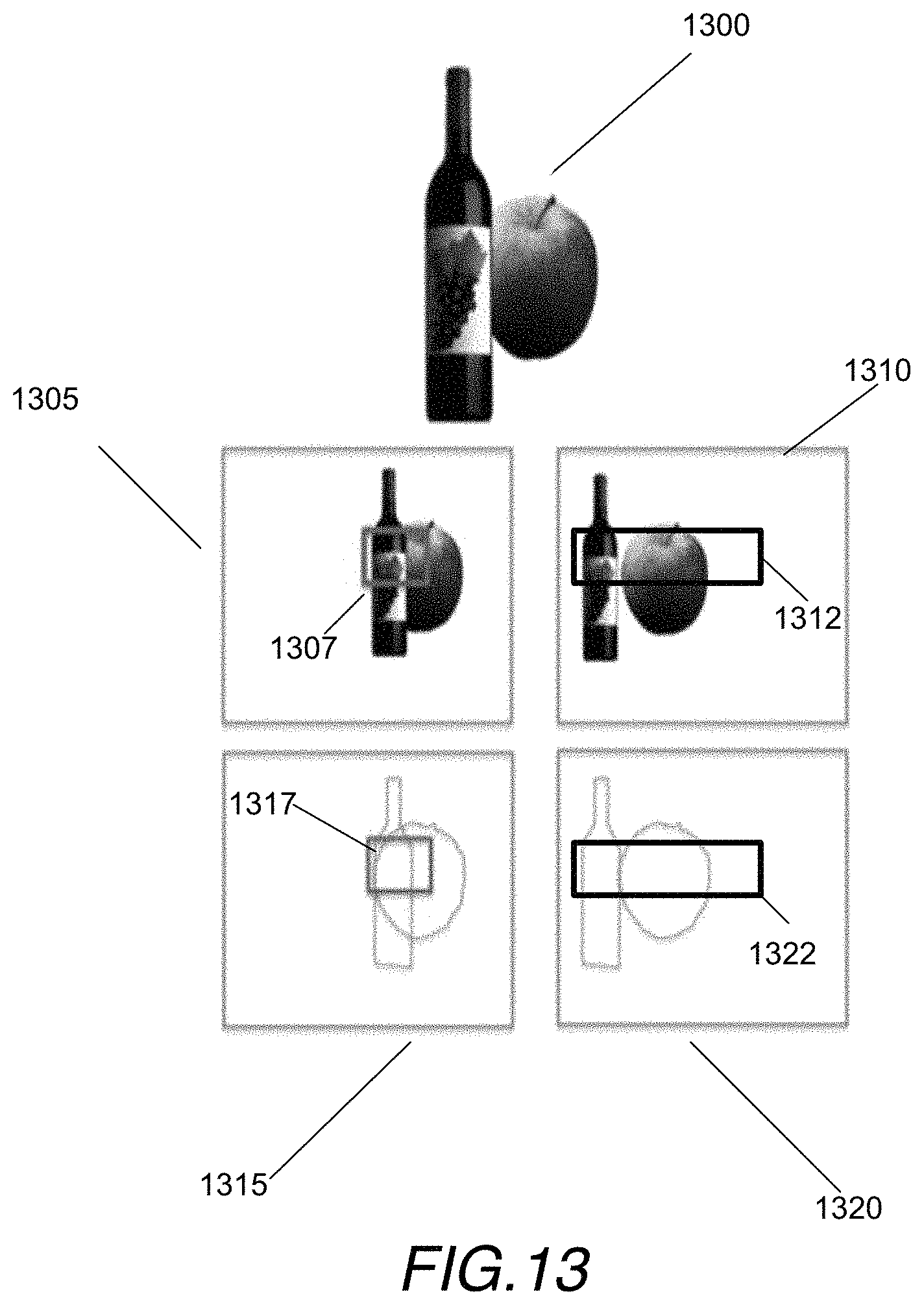
D00014

M00001

XML
uspto.report is an independent third-party trademark research tool that is not affiliated, endorsed, or sponsored by the United States Patent and Trademark Office (USPTO) or any other governmental organization. The information provided by uspto.report is based on publicly available data at the time of writing and is intended for informational purposes only.
While we strive to provide accurate and up-to-date information, we do not guarantee the accuracy, completeness, reliability, or suitability of the information displayed on this site. The use of this site is at your own risk. Any reliance you place on such information is therefore strictly at your own risk.
All official trademark data, including owner information, should be verified by visiting the official USPTO website at www.uspto.gov. This site is not intended to replace professional legal advice and should not be used as a substitute for consulting with a legal professional who is knowledgeable about trademark law.