System And Methods For Depth Regularization And Semiautomatic Interactive Matting Using Rgb-d Images
SRIKANTH; Manohar ; et al.
U.S. patent application number 16/148816 was filed with the patent office on 2019-01-31 for system and methods for depth regularization and semiautomatic interactive matting using rgb-d images. The applicant listed for this patent is FotoNation Limited. Invention is credited to Priyam CHATTERJEE, Ravi RAMAMOORTHI, Manohar SRIKANTH, Kartik VENKATARAMAN.
| Application Number | 20190037150 16/148816 |
| Document ID | / |
| Family ID | 54017866 |
| Filed Date | 2019-01-31 |
View All Diagrams
| United States Patent Application | 20190037150 |
| Kind Code | A1 |
| SRIKANTH; Manohar ; et al. | January 31, 2019 |
SYSTEM AND METHODS FOR DEPTH REGULARIZATION AND SEMIAUTOMATIC INTERACTIVE MATTING USING RGB-D IMAGES
Abstract
Systems and methods in accordance with embodiments of this invention perform depth regularization and semiautomatic interactive matting using images. In an embodiment of the invention, the image processing pipeline application directs a processor to receive (i) an image (ii) an initial depth map corresponding to the depths of pixels within the image, regularize the initial depth map into a dense depth map using depth values of known pixels to compute depth values of unknown pixels, determine an object of interest to be extracted from the image, generate an initial trimap using the dense depth map and the object of interest to be extracted from the image, and apply color image matting to unknown regions of the initial trimap to generate a matte for image matting.
| Inventors: | SRIKANTH; Manohar; (Mountain View, CA) ; RAMAMOORTHI; Ravi; (Santa Clara, CA) ; VENKATARAMAN; Kartik; (San Jose, CA) ; CHATTERJEE; Priyam; (Sunnyvale, CA) | ||||||||||
| Applicant: |
|
||||||||||
|---|---|---|---|---|---|---|---|---|---|---|---|
| Family ID: | 54017866 | ||||||||||
| Appl. No.: | 16/148816 | ||||||||||
| Filed: | October 1, 2018 |
Related U.S. Patent Documents
| Application Number | Filing Date | Patent Number | ||
|---|---|---|---|---|
| 14642637 | Mar 9, 2015 | 10089740 | ||
| 16148816 | ||||
| 61949999 | Mar 7, 2014 | |||
| Current U.S. Class: | 1/1 |
| Current CPC Class: | G06T 2207/10028 20130101; G06T 2200/24 20130101; H04N 5/232935 20180801; H04N 13/15 20180501; H04N 13/271 20180501; G06T 7/194 20170101; G06T 2200/28 20130101; H04N 2013/0081 20130101; H04N 5/272 20130101; G06T 7/11 20170101; H04N 5/23293 20130101; G06T 2207/10024 20130101; H04N 5/2621 20130101; H04N 5/23218 20180801; H04N 5/23216 20130101; H04N 5/232939 20180801; G06T 2207/20096 20130101 |
| International Class: | H04N 5/262 20060101 H04N005/262; H04N 5/232 20060101 H04N005/232; H04N 5/272 20060101 H04N005/272 |
Claims
1. An image matting system, comprising: at least one processor for executing sets of instructions; memory containing an image processing pipeline application; wherein the image processing pipeline application directs the processor to: receive (i) an image comprising a plurality of pixel color values for pixels in the image and (ii) an initial depth map corresponding to the depths of the pixels within the image; regularize the initial depth map into a dense depth map using depth values of known pixels to compute depth values of unknown pixels; determine an object of interest to be extracted from the image; generate an initial trimap using the dense depth map and the object of interest to be extracted from the image; and apply color image matting to unknown regions of the initial trimap to generate a matte for image matting.
2. The image matting system of claim 1, further comprising: a camera that captures images of a scene; and a display on the camera for providing a preview of the scene.
3. The image matting system of claim 2, wherein the image processing application further directs the processor to: detect an insufficient separation between the object of interest and remaining portions of the scene being captured; and provide a notification within the display of the camera to capture a new image at a suggested setting.
4. The image matting system of claim 2, wherein the image processing application further directs the processor to: capture a candidate image using the camera; displaying the candidate image on the display of the camera; receiving a selection of the portion of the image for image matting through a user interface of the camera; and wherein generating the initial trimap comprises using the selected portion of the image to determine foreground and background pixels of the image in the initial trimap.
5. The image matting system of claim 1, wherein regularizing the initial depth map into a dense depth map comprises performing Laplacian matting to compute a Laplacian L.
6. The image matting system of claim 5, wherein the image processing application further directs the processor to prune the Laplacian L.
7. The image matting system of claim 6, wherein pruning the Laplacian L comprises: for each pair i,j of pixels in affinity matrix A, determine if i and j have depth differences beyond a threshold; and if the difference is beyond the threshold, purge the pair i,j within the affinity matrix A.
8. The image matting system of claim 6, wherein the image processing application further directs the processor to: detect and correct depth bleeding across edges by computing a Laplacian residual R and removing incorrect depth values based on the Laplacian residual R.
9. The image matting system of claim 8, wherein the computing the Laplacian residual R comprises computing R=Lz* where z* is the regularized depth map, wherein removing incorrect depth values comprises identifying regions where R>0.
10. The image matting system of claim 1, wherein the image is defined according to a red, green, blue (RGB) color model.
11. The image matting system of claim 2, wherein the camera is at least one select from the group consisting of an array camera, a light-field camera, a time-of-flight depth camera, and a camera equipped with a depth sensor.
12. The image matting system of claim 1, wherein the image processing application further directs the processor to determine the object of interest to be extracted from the image using at least one selected from the group consisting of: face recognition and object recognition to automatically identify the object of interest in the image.
13. The image matting system of claim 2, wherein the image processing application further directs the processor to: receive a user touch input on the display of the camera indicating at least one selected from the group consisting: an object of interest, foreground region of the image, and background region of the image.
14. The image matting system of claim 1, wherein the image processing application further directs the processor to place the object of interest on a new background as a composite image.
15. The image matting system of claim 1, wherein the initial depth map is received from a device used to capture the image, wherein the device is at least one selected from the group consisting of: a camera, an array camera, a depth sensor, a time-of-flight camera, and a light-field camera.
16. An array camera, comprising: a plurality of cameras that capture images of a scene from different viewpoints; memory containing an image processing pipeline application; wherein the image processing pipeline application direct the processor to: receive (i) an image comprising a plurality of pixel color values for pixels in the image and (ii) an initial depth map corresponding to the depths of the pixels within the image; regularize the initial depth map into a dense depth map using depth values of known pixels to compute depth values of unknown pixels; determine an object of interest to be extracted from the image; generate an initial trimap using the dense depth map and the object of interest to be extracted from the image; and apply color image matting to unknown regions of the initial trimap to generate a matte for image matting.
17. The array camera of claim 1, wherein the image processing pipeline application further directs the processer to: capture a set of images using a group of cameras; determine the initial depth map using the set of images.
18. The array camera of claim 17, wherein regularizing the initial depth map into a dense depth map comprises performing Laplacian matting to compute a Laplacian L.
19. The array camera of claim 18, wherein the image processing application further directs the processor to prune the Laplacian L, wherein pruning the Laplacian L comprises: for each pair i,j of pixels in affinity matrix A, determine if i and j have depth differences beyond a threshold; and if the difference is beyond the threshold, purge the pair i,j within the affinity matrix A.
20. The array camera of claim 19, wherein the image processing application further directs the processor to: detect and correct depth bleeding across edges by computing a Laplacian residual R and removing incorrect depth values based on the Laplacian residual R.
Description
RELATED APPLICATIONS
[0001] This application claims priority to U.S. patent application Ser. No. 14/642,637 filed Mar. 9, 2015 which claims priority to U.S. patent application Ser. No. 61/949,999 filed Mar. 7, 2014, the disclosures of which are incorporated by reference herein in their entirety.
FIELD OF INVENTION
[0002] The present invention relates image matting using depth information. In particular, the present invention relates to automatic generation of a trimap for image matting using a regularized depth map and/or interactive user input.
BACKGROUND
[0003] Image matting is the process of extracting an object of interest (e.g., a foreground object) from its background an important task in image and video editing. Image matting may be used for a variety of different purposes, such as to extract an object for placement with a different background image. Current techniques exist that may be used to determine which pixels belong to the foreground object and which pixels are part of the background. In particular, many current approaches generally estimate foreground and background colors based on color values of nearby pixels, where they are known, or perform iterative nonlinear estimation by alternating foreground and background color estimation with alpha estimation. Conventional matting operations, however, could result in errors in describing certain portions of images that are more difficult to identify as belonging to the background or foreground of the image.
SUMMARY OF THE INVENTION
[0004] Systems and methods in accordance with embodiments of this invention perform depth regularization and semiautomatic interactive matting using images. In an embodiment of the invention, an image matting system includes at least one processor for executing sets of instructions, memory containing an image processing pipeline application. In an embodiment of the invention, the image processing pipeline application directs the processor to receive (i) an image comprising a plurality of pixel color values for pixels in the image and (ii) an initial depth map corresponding to the depths of the pixels within the image; regularize the initial depth map into a dense depth map using depth values of known pixels to compute depth values of unknown pixels; determine an object of interest to be extracted from the image; generate an initial trimap using the dense depth map and the object of interest to be extracted from the image; and apply color image matting to unknown regions of the initial trimap to generate a matte for image matting.
[0005] In another embodiment of the invention, the image matting system further includes: a camera that captures images of a scene; and a display on the camera for providing a preview of the scene.
[0006] In yet another embodiment of the invention, the image processing application further directs the processor to: detect an insufficient separation between the object of interest and remaining portions of the scene being captured; and provide a notification within the display of the camera to capture a new image at a suggested setting.
[0007] In still yet another embodiment of the invention, the image processing application further directs the processor to: capture a candidate image using the camera; display the candidate image on the display of the camera; receive a selection of the portion of the image for image matting through a user interface of the camera, where generating the initial trimap includes using the selected portion of the image to determine foreground and background pixels of the image in the initial trimap.
[0008] In a still further embodiment of the invention, regularizing the initial depth map into a dense depth map includes performing Laplacian matting to compute a Laplacian L.
[0009] In still a further embodiment of the invention, the image processing application directs the processor to prune the Laplacian L.
[0010] In another embodiment of the invention, pruning the Laplacian L includes: for each pair i,j of pixels in affinity matrix A, determine if i and j have depth differences beyond a threshold; and if the difference is beyond the threshold, purge the pair i,j within the affinity matrix A.
[0011] In still another embodiment of the invention, the image processing application further directs the processor to detect and correct depth bleeding across edges by computing a Laplacian residual R and removing incorrect depth values based on the Laplacian residual R.
[0012] In another embodiment of the invention, the image processing application computes the Laplacian residual R by computing R=Lz* where z* is the regularized depth map, where removing incorrect depth values includes identifying regions where R>0.
[0013] In a further embodiment of the invention, the image is defined according to a red, green, blue (RGB) color model.
[0014] In still another embodiment, the camera is at least one select from the group consisting of an array camera, a light-field camera, a time-of-flight depth camera, and a camera equipped with a depth sensor.
[0015] In a yet further embodiment, the image processing application further directs the processor to determine the object of interest to be extracted from the image using at least one selected from the group consisting of: face recognition and object recognition to automatically identify the object of interest in the image.
[0016] In another embodiment again, the image processing application further directs the processor to: receive a user touch input on the display of the camera indicating at least one selected from the group consisting: an object of interest, foreground region of the image, and background region of the image.
[0017] In another embodiment yet again, the image processing application further directs the processor to place the object of interest on a new background as a composite image.
[0018] In a still further embodiment, the initial depth map is received from a device used to capture the image, where the device is at least one selected from the group consisting of: a camera, an array camera, a depth sensor, a time-of-flight camera, and a light-field camera.
[0019] An embodiment of the invention includes an array camera, including: a plurality of cameras that capture images of a scene from different viewpoints; memory containing an image processing pipeline application; where the image processing pipeline application direct the processor to: receive (i) an image comprising a plurality of pixel color values for pixels in the image and (ii) an initial depth map corresponding to the depths of the pixels within the image; regularize the initial depth map into a dense depth map using depth values of known pixels to compute depth values of unknown pixels; determine an object of interest to be extracted from the image; generate an initial trimap using the dense depth map and the object of interest to be extracted from the image; and apply color image matting to unknown regions of the initial trimap to generate a matte for image matting.
[0020] In a further embodiment, the image processing pipeline application further directs the processer to: capture a set of images using a group of cameras and determine the initial depth map using the set of images.
[0021] In yet a further embodiment of the invention, the image processing pipeline application regularizes the initial depth map into a dense depth map by performing Laplacian matting to compute a Laplacian L.
[0022] In yet another embodiment of the invention, the image processing application further directs the processor to prune the Laplacian L, wherein pruning the Laplacian L includes for each pair i,j of pixels in affinity matrix A, determine if i and j have depth differences beyond a threshold; and if the difference is beyond the threshold, purge the pair i,j within the affinity matrix A.
[0023] In still a further embodiment of the invention, the image processing application further directs the processor to detect and correct depth bleeding across edges by computing a Laplacian residual R and removing incorrect depth values based on the Laplacian residual R.
BRIEF DESCRIPTION OF THE DRAWINGS
[0024] FIG. 1A conceptually illustrates an array camera in accordance with an embodiment of the invention.
[0025] FIG. 1B illustrates a process for interactive guided image capture for image matting in accordance with embodiments of the invention.
[0026] FIGS. 1C-1E conceptually illustrate examples of notifications provided to a user based on a captured candidate image in accordance with an embodiment of the invention.
[0027] FIG. 1F illustrates a process for depth regularization and semiautomatic interactive matting in accordance with an embodiment of the invention.
[0028] FIG. 1G conceptually illustrates an overall pipeline for semi-automatic interactive image matting in accordance with an embodiment of the invention.
[0029] FIG. 2 conceptually illustrates an example of depth map regularization for a sample 3D scene in accordance with an embodiment of the invention.
[0030] FIG. 3 conceptually illustrates Laplacian pruning and residual correction of a depth map in accordance with an embodiment of the invention.
[0031] FIG. 4 conceptually illustrates an example of depth regularization of an image produced from an array camera in accordance with an embodiment of the invention.
[0032] FIG. 5 conceptually illustrates a depth regularization comparison with several different depth sensors in accordance with embodiments of the invention.
[0033] FIG. 6 conceptually illustrates applications of regularized depths in accordance with embodiments of the invention.
[0034] FIG. 7 conceptually illustrates fully automatic image matting using object recognition in accordance with an embodiment of the invention.
[0035] FIG. 8 conceptually illustrates two mattes computed with an embodiment of the image matting system, one on a color RGB alpha matting benchmark and one with an embodiment of the image matting system.
[0036] FIG. 9 conceptually illustrates the speedup of an embodiment of the image matting system versus KNN matting in accordance with an embodiment of the invention.
[0037] FIG. 10 conceptually illustrates interactive editing of trimaps with real-time feedback in accordance with an embodiment of the invention.
[0038] FIG. 11 conceptually illustrates an example of an additional efficiency optimization tocolor matting to also solve for foreground and background efficiently in accordance with an embodiment of the invention.
[0039] FIG. 12 conceptually illustrates an example of a fast approximation optimization in accordance with an embodiment of the invention.
[0040] FIG. 13 conceptually illustrates a first example of semi-automatic interactive image matting in accordance with an embodiment of the invention.
[0041] FIG. 14 conceptually illustrates a second example of semi-automatic interactive image matting in accordance with an embodiment of the invention.
[0042] FIG. 15 conceptually illustrates a third example of semi-automatic interactive image matting in accordance with an embodiment of the invention.
[0043] FIG. 16 conceptually illustrates a fourth example of semi-automatic interactive image matting in accordance with an embodiment of the invention.
[0044] FIG. 17 conceptually illustrates a fifth example of semi-automatic interactive image matting in accordance with an embodiment of the invention.
[0045] FIG. 18 conceptually illustrates a sixth example of semi-automatic interactive image matting in accordance with an embodiment of the invention.
DETAILED DESCRIPTION
[0046] Turning now to the drawings, systems and methods for depth regularization and semiautomatic interactive matting using depth information in images in accordance with embodiments of the invention are illustrated. In some embodiments, a camera may be used to capture images for use in image matting. In several embodiments, the camera may also provide information regarding depth to objects within a scene captured by an image that may be used in image matting. In many embodiments, the depth information may be captured using any one of array cameras, time-of-flight depth cameras, light-field cameras, and/or cameras that include depth sensors, among various other types of devices capable of capturing images and/or providing depth information. In several embodiments, the depth information may be obtained through various other methods, such as using a camera that captures multiple images and computing depth information from motion, multiple images captured with different focal lengths and computing depth from defocus, among various other methods for obtaining depth information.
[0047] In a number of embodiments, in image matting, the depth information may be used to generate a trimap for use in image matting. In particular, in several embodiments, the trimap may be generated based on the depth of the pixels of the foreground relative to the depth of the pixels in the background. The discussion below may use the term "foreground object" to indicate an object of interest that is to be extracted from an image through image matting, however, this object does not necessarily have to be positioned as the foremost object in the foreground of the image, but may be located at any variety of different depths within the image. However, typically users generally are interested in extracting the foreground object(s) (e.g., faces, people, among other items) appearing in an image during image matting and for purposes of this discussion, the term foreground object may be used to specify the particular object of interest that is to be extracted with image matting.
[0048] In certain embodiments, a user may provide an indication of the object of interest (i.e., foreground object) to be extracted from an image through various types of user input and/or interaction with the device. In many embodiments, the user input may be a single stroke indicating an object of interest, a foreground and/or background of the image. In various embodiments, the image matting system may use face recognition and/or object recognition to avoid user input entirely during the image matting process.
[0049] In some embodiments, the camera may capture a candidate image and provide a preview display of the candidate image to a user and the user may then provide user input that indicates an object of interest that is to be extracted from the candidate image through image matting. In several embodiments, an image-matting system can be utilized to determine whether the indicated object of interest within the candidate image can be readily extracted from the captured candidate image or if the user should modify certain aspects of the scene being captured and/or camera settings to provide for a better candidate image for use in the matting of the indicated object of interest. In particular, in some embodiments, the camera may provide a notification to adjust the separation between the camera, foreground object of interest, and/or background relative to one another in order to provide the user with the ability to capture a better candidate image and/or depth information for use in image matting of the indicated object of interest.
[0050] As described above, the preview display of the camera in some embodiments may display a notification to the user to adjust certain properties of the camera and/or scene being captured. For example, the display may provide a notification to the user to increase the distance (i.e., separation) between the object of interest and the background, to decrease the distance between the camera lens and the object of interest (e.g., move the camera towards the object of interest or move the object closer to the camera), and/or to increase the distance both between the background, object of interest, and camera lens. In some embodiments, the particular recommendation provided within the notification may vary based on the characteristics of the candidate image and/or scene settings.
[0051] In some embodiments, the image matting system may also use the user input identifying the object of interest, foreground, and/or background of the image during various stages of the image matting process, including during the generation of the trimap from the user input.
[0052] As described above, in many embodiments, the camera may capture color images (e.g., RGB images) that also provide depth information of the scene being captured. In certain embodiments, the initial depth information is provided as an initial sparse depth map. In particular, the initial sparse depth map may not have depth values for all pixels within the captured image, or may have depth values that are below a certain confidence value regarding the accuracy of the depth, for a certain portion of the pixels within the image.
[0053] In order to be able to use the initial sparse depth map for image matting, the sparse depth map can be regularized into a dense depth map. In a number of embodiments, the dense depth map is created using an affine combination of depths at nearby pixels to compute depths for unknown and/or ambiguous pixel depths. In several embodiments, the image matting system uses dense depth regularization and matting within a unified Laplacian framework. In certain embodiments, the image matting system may also use the Laplacian residual to correct input depth errors. In particular, the resulting dense depth map may be fairly accurate in most regions, but may not be as precise at boundaries as image pixel values. Therefore, some embodiments utilize depth discontinuities in RGB-D images to automate creation of a thin uncertain region in a trimap. In these embodiments, the user may mark as little as a single foreground and/or background stroke to provide an indication of the object of interest to be extracted with image matting. In some embodiments, the image matting system may also use occlusion and visibility information to automatically create an initial trimap.
[0054] In some embodiments, the image matting system uses the dense depth map for trimap generation for use in image matting. In particular, based on an identified object of interest, in some embodiments, the image matting system generates an initial trimap with thin uncertain regions by doing a segmentation based on depth into parts of the image closer to the foreground or background depth.
[0055] Upon generating the initial trimap using the dense depth map, the image matting system can apply conventional color matting (e.g,. conventional Laplacian color matting) based on the color image to the initial thin tripmap to extract the object of interest, using an optimization to the conventional color matting that solves a reduced linear system for alpha values in only the uncertain regions of the trimap. In particular, the image matting system may use an efficient color matting algorithm that utilizes a reduced linear system to compute alpha values only at unknown pixels and to generate the matte to use for image matting, achieving speedups of one to two orders of magnitude. This also lends itself to incremental computation, enabling interactive changes to the initial automatically-generated trimap, with real-time updates of the matte. In some embodiments, the image matting system may use the matte to extract the object of interest and subsequently overlay the object of interest and/or composite it with other images including (but not limited to) background images.
[0056] Image matting using depth information from images, dense depth map regularization, and optimizations to conventional color matting processes in accordance with embodiments of the invention are described below.
Array Cameras
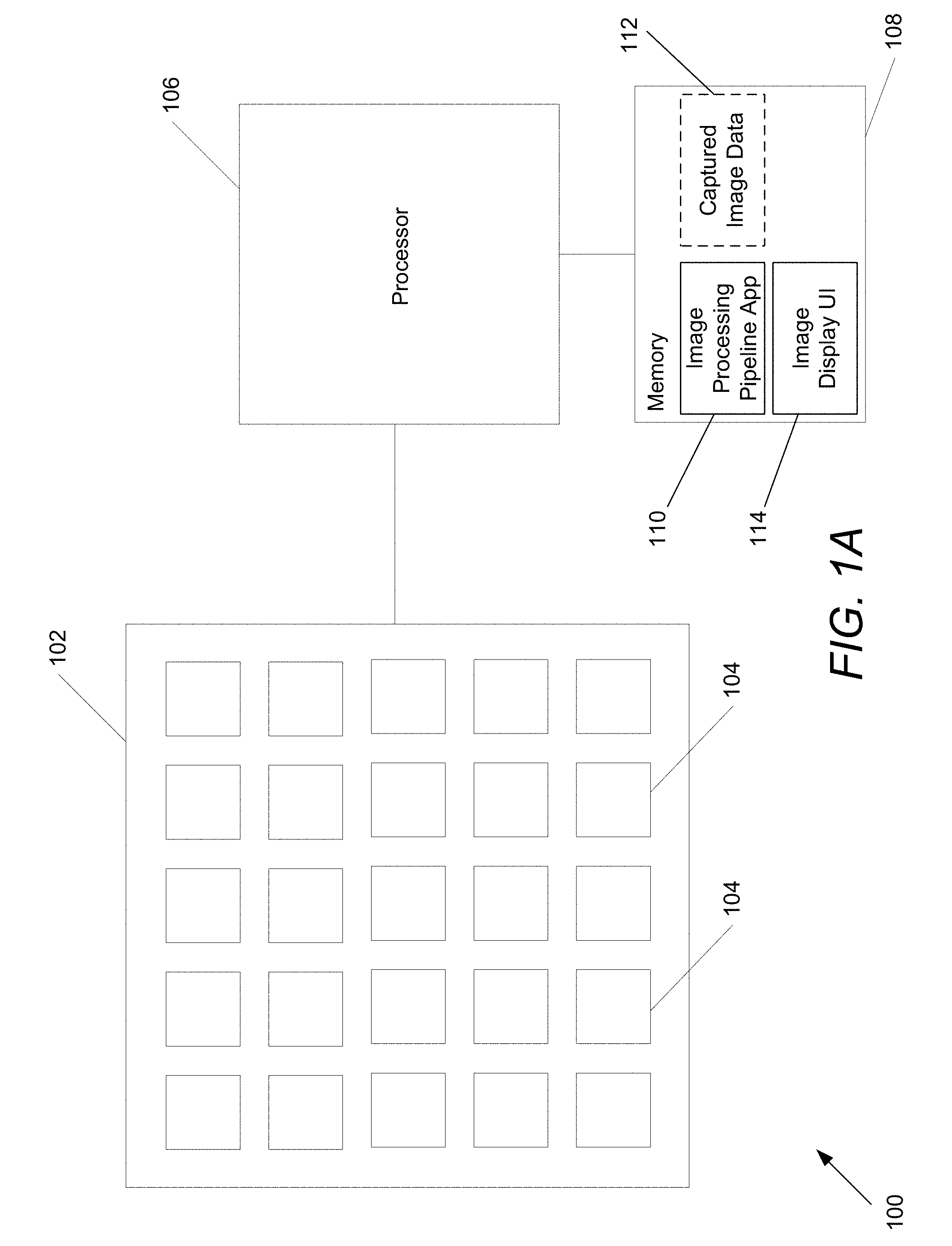
[0057] As described above, an array camera may be used to capture color images that include depth information for use in image matting. Array cameras in accordance with many embodiments of the invention can include an array camera module including an array of cameras and a processor configured to read out and process image data from the camera module to synthesize images. An array camera in accordance with an embodiment of the invention is illustrated in FIG. 1A. The array camera 100 includes an array camera module 102 with an array of individual cameras 104, where an array of individual cameras refers to a plurality of cameras in a particular arrangement, such as (but not limited to) the square arrangement utilized in the illustrated embodiment. In other embodiments, any of a variety of grid or non-grid arrangements of cameras can be utilized. Various array camera configurations including monolithic and monolithic arrays incorporating various different types of cameras are disclosed in U.S. Patent Publication No. 2011/0069189 entitled "Capturing and Processing of Images Using Monolithic Camera Array with Heterogeneous Imagers" to Venkataraman et al., the relevant disclosure with respect to different array camera configurations including (but not limited to) the disclosure with respect to arrays of arrays is hereby incorporated by reference herein in its entirety. The array camera module 102 is connected to the processor 106. The processor is also configured to communicate with one or more different types of memory 108 that can be utilized to store an image processing pipeline application 110, image data 112 captured by the array camera module 102, image matting application 108, and an image display UI 114. The image processing pipeline application 110 is typically non-transitory machine readable instructions utilized to direct the processor to perform processes including (but not limited to) the various processes described below. In several embodiments, the processes include coordinating the staggered capture of image data by groups of cameras within the array camera module 102, the estimation of depth information from the captured image data 112 and image matting of the captured images using the captured image data, include the captured depth information. The image display UI 114 receives user inputs on a display of the array camera regarding portions of a captured image to be extracted during image matting and displays the captured images on a display of the device. In some embodiments, the image display UI 114 may continuously receive user inputs for portions of a captured image to be extracted during image matting and provide these inputs to the image processing pipeline application 110. In some embodiments, the image processing pipeline application 110 may determine whether a captured image is optimal for image matting and based on this determination, provides a notification, via the image display UI 114, providing a suggestion for capturing an image to use for image matting.
[0058] Processors 108 in accordance with many embodiments of the invention can be implemented using a microprocessor, a coprocessor, an application specific integrated circuit and/or an appropriately configured field programmable gate array that is directed using appropriate software to take the image data captured by the cameras within the array camera module 102 and apply image matting to captured images in order to extract one or more objects of interest from the captured images.
[0059] In several embodiments, a captured image is rendered from a reference viewpoint, typically that of a reference camera 104 within the array camera module 102. In many embodiments, the processor is able to synthesize the captured image from one or more virtual viewpoints, which do not correspond to the viewpoints of any of the focal planes 104 in the array camera module 102. Unless all of the objects within a captured scene are a significant distance from the array camera, the images of the scene captured within the image data will include disparity due to the different fields of view of the cameras used to capture the images. Processes for detecting and correcting for disparity are discussed further below. Although specific array camera architectures are discussed above with reference to FIG. 1A, alternative architectures can also be utilized in accordance with embodiments of the invention.
[0060] Array camera modules that can be utilized in array cameras in accordance with embodiments of the invention are disclosed in U.S. Patent Publication 2011/0069189 entitled "Capturing and Processing of Images Using Monolithic Camera Array with Heterogeneous Imagers", to Venkataraman et al. and U.S. patent application Ser. No. 14/536,537 entitled "Methods of Manufacturing Array Camera Modules Incorporating Independently Aligned Lens Stacks," to Rodda et al., which are hereby incorporated by reference in their entirety. Array cameras that include an array camera module augmented with a separate camera that can be utilized in accordance with embodiments of the invention are disclosed in U.S. patent application Ser. No. 14/593,369 entitled "Array Cameras Including An Array Camera Module Augmented With A Separate Camera," to Venkataraman et al., and is herein incorporated by reference in its entirety. The use of image depth information for image matting in accordance with embodiments of the invention is discussed further below.
Guided Image Capture for Image Matting
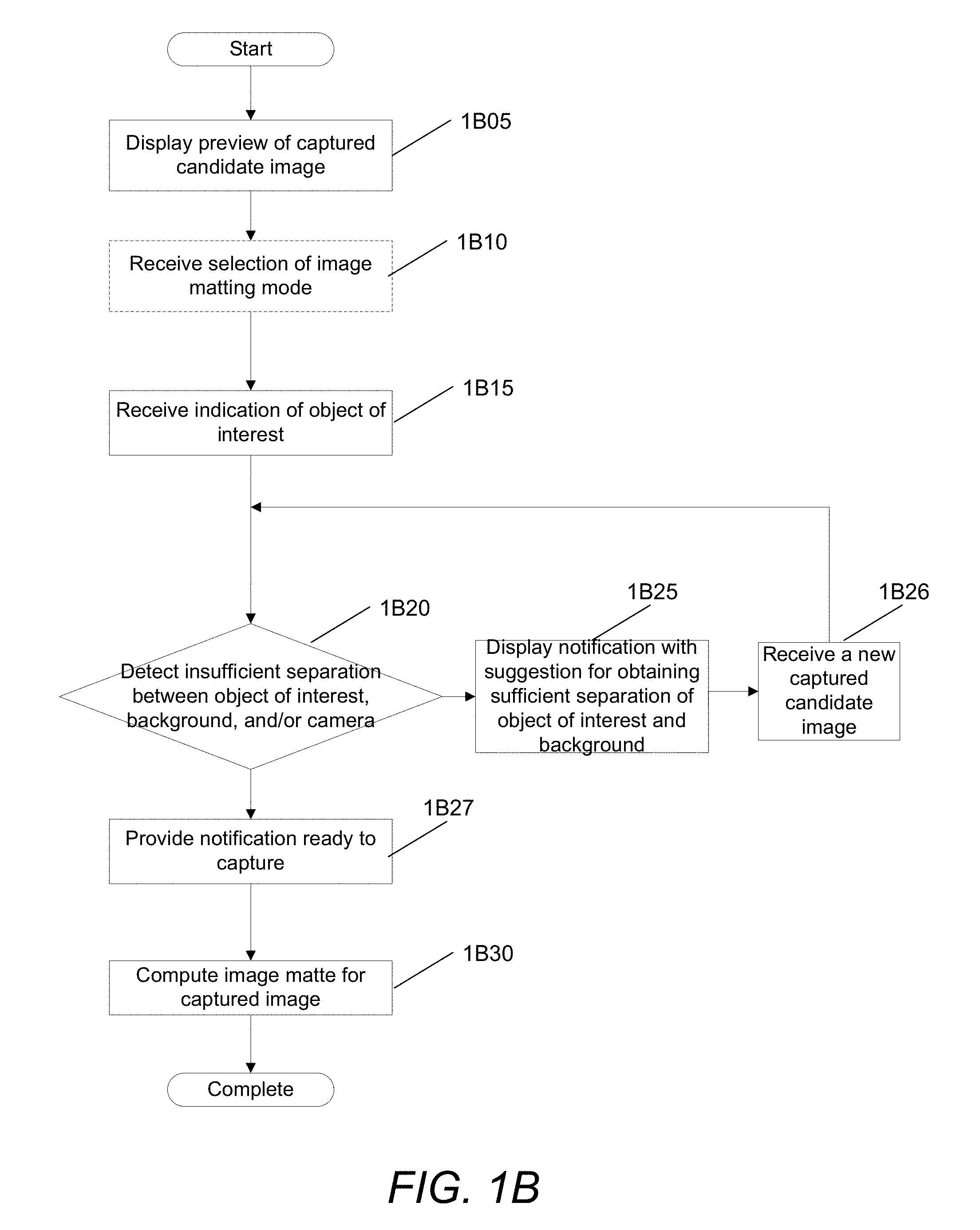
[0061] In some embodiments, the image matting system guides a user to allow the user to capture a better quality image for image matting. In particular, a camera display can provide a notification to a user to adjust camera settings and/or physical composition of the imaged scene for better image matting results. For example, the camera may display real-time notifications to the user to move the object of interest closer to the camera lens, move the object of intrest further away from the background, among various other possible notifications that would allow an image to be captured that is optimized for image matting. A process for guided image capture for image matting in accordance with an embodiment of the invention is illustrated in FIG.1B.
[0062] The process displays 1B05 a preview of a captured candidate image. In some embodiments, the image may be captured by a camera, such as an array camera, time-of-flight camera, light-field camera, among various other types of cameras. In some embodiments, the image being previewed may be captured from a camera while the depth information may be provided by a depth sensor, such as a secondary depth camera.
[0063] In some embodiments, the process displays a preview of an image (and the user does not necessarily need to provide a command to capture the image), for example, through a real-time display of the image that is being imaged by the lens of the camera device.
[0064] The process may, optionally, receive 1B10 a selection of an image matting mode. For example, a user may select the image matting mode on the camera. The image matting mode may be used to extract an object of interest from the candidate image.
[0065] The process receives 1B15 an indication of an object of interest that is to be extracted from the candidate image and/or image being previewed within the display. The selection may be received from a user input identifying the object of interest (e.g., a foreground object), such as a user stroke over the object of interest, a user touch of the display, among various other mechanisms. In some embodiments, the object of interest may be automatically identified using one or more different object recognition processes. In particular, some embodiments may use face recognition processes to automatically identify the object(s) of interest.
[0066] The process determines (at 1B20) whether it detects an insufficient separation between the object of interest, foreground, background, and/or the camera. If the process determines (at 1B20) that it does not detect an insufficient separation, the process may provide (at 1B27) a notification that it is ready to capture the image (upon which the user may trigger the capturing of an image) and the process may compute (1B30) the image matte for the captured image.
[0067] In some embodiments, in order to determine whether a candidate image provides a sufficient separation, the process estimates depths of pixels in the candidate image scene and determines whether the depths of the object of interest are within a threshold of the depths of the foreground and/or background remaining scene. In some embodiments, the process regularized the sparse depth map into a dense depth map. Techniques for depth regularization are described in detail below.
[0068] Based on the dense depth map, in several embodiments, the process computes a histogram and analyzes the distribution of pixels to determine the existence of a prominent foreground object (or object of interest) and a distribution of one or more background depths. In some embodiments, the process uses an automated threshold to separate the foreground object of interest from the background. As described above, when the object of interest is not necessarily the foremost object within the image, some embodiments may use a second threshold to exclude the foreground from the object of interest as well. In several embodiments, once a satisfactory separation of the distribution/histogram of the object of interest is obtained from the distribution/histogram of depths for the rest of the scene, the process determines that the scene satisfies criteria optimal for image matting.
[0069] If the process determines (at 1B20) that it detects an insufficient separation between the object of interest, foreground, background, and/or camera, the process displays (at 1B25) a notification with a suggestion for obtaining a sufficient separation between the object of interest, foreground, background, and/or camera that is optimized for image matting.
[0070] The process then receives a new captured candidate image, and the initial sparse depth map for the image, for image matting and returns to 1B20 to determine whether the new candidate image is of a sufficient quality for image matting. This process can iterate until a candidate image with sufficient quality is captured.
[0071] The process then completes. Although specific processes are described above with respect to FIG. 1B with respect to guided image capture for image matting, any of a variety of processes can be utilized to provide physical (e.g., vibrations), audio and/or visual guides via a user interface to direct image capture for improved image matting quality as appropriate to the requirements of specific applications in accordance with embodiments of the invention. Several examples of guided image capture will now be described.
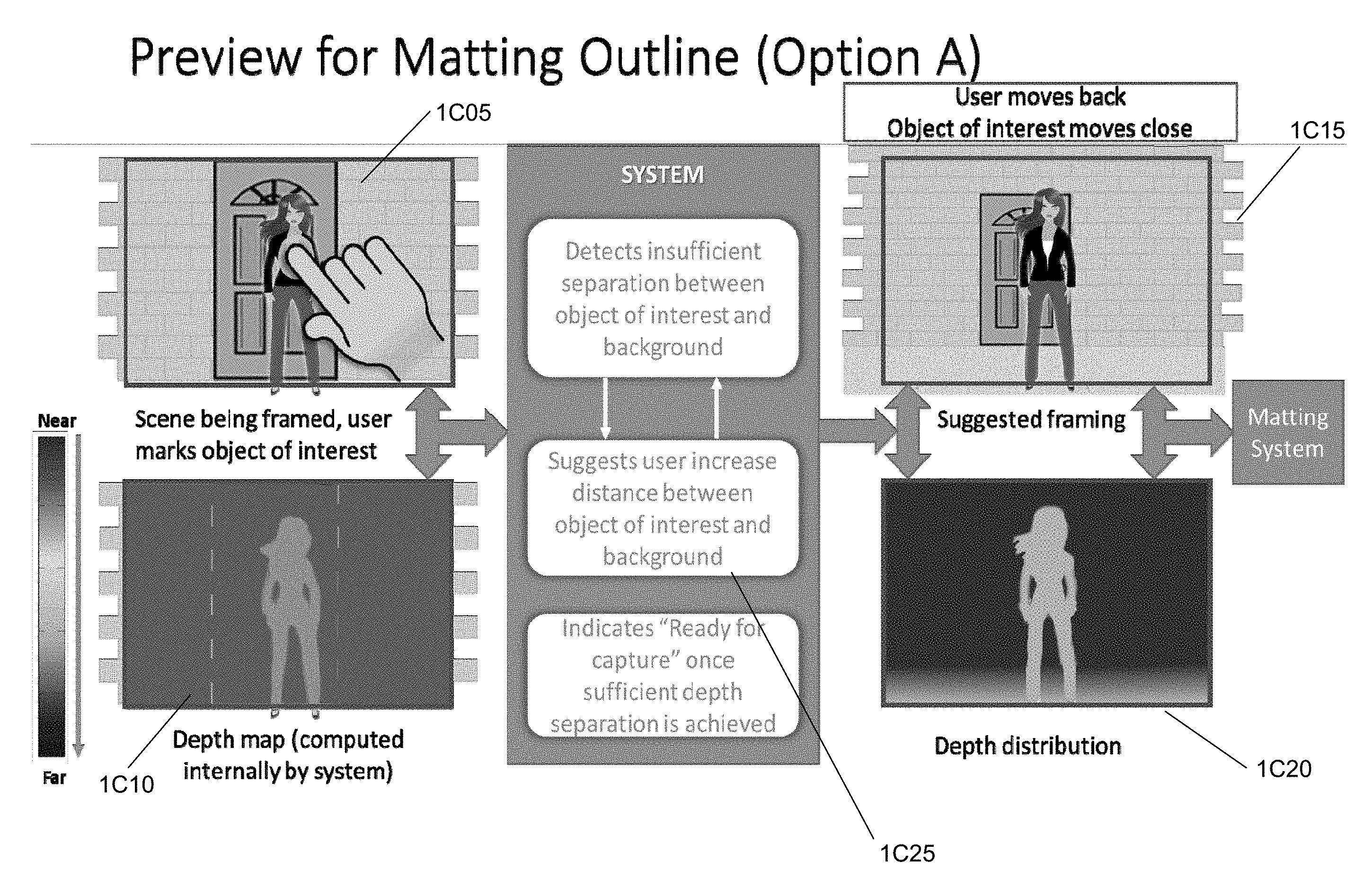
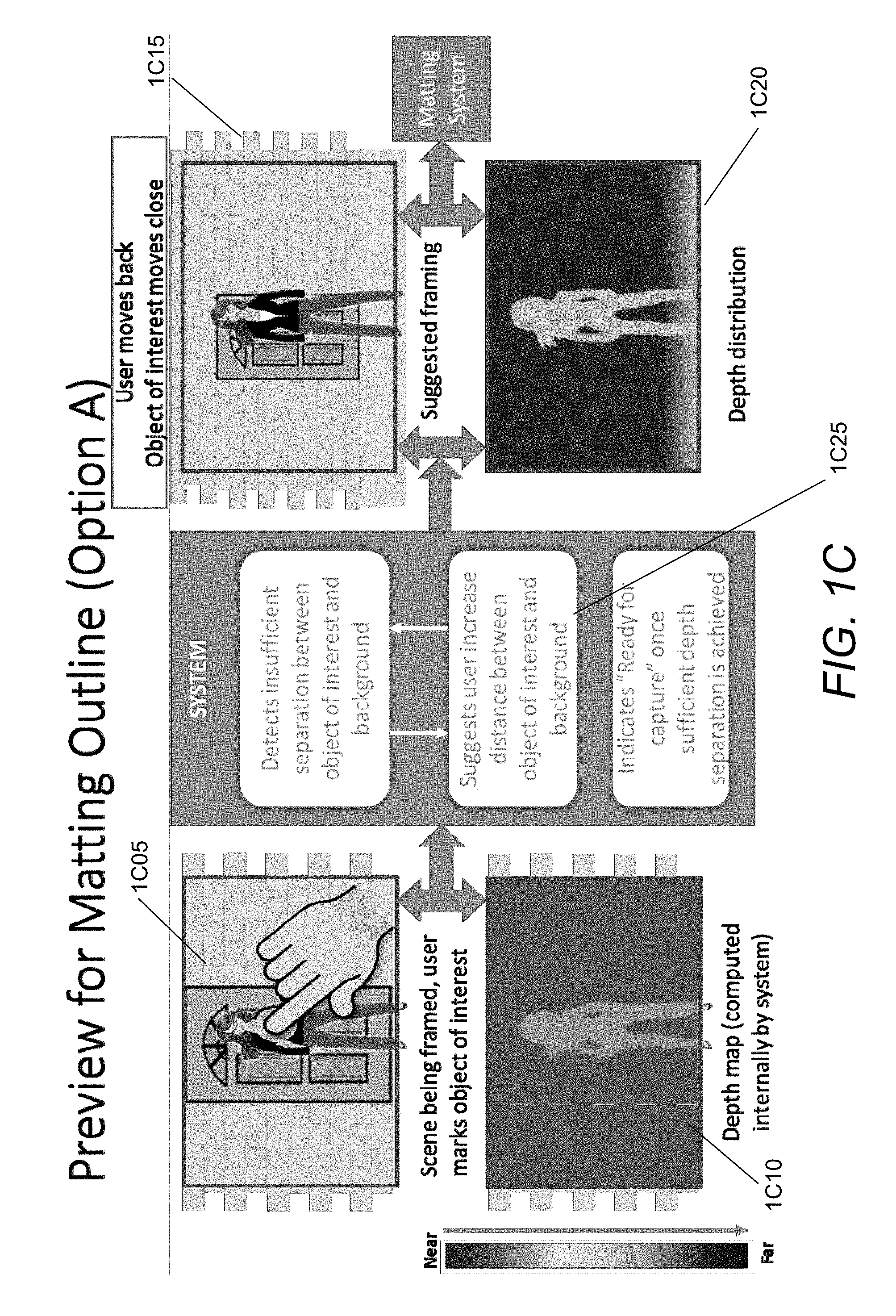
[0072] FIGS. 1C-1E illustrate several examples of various different notifications that may be provided to a user via a camera user interface based on a detection of an insufficient separation between a foreground object for image matting. In particular, FIG. 1C illustrates a candidate captured image 1C05 for image matting. In the candidate captured image 1C05, the user is selecting an object of interest of a person standing in front of a door. The image matting system computes a depth map 1C10 for the captured image. As illustrated in the depth map 1C10, the color coding for the depth of the person is a light shade of blue and that of the background is a slightly darker shade of blue, which, according to the depth key, indicate that there is relatively small depth separation between the object of interest and background.
[0073] Likewise the image matting system has detected an insufficient separation between the object of interest (i.e., the person) and the background (i.e., the door and wall), and thus provides a notification 1C25 with a suggestion that the user increase the distance between the object of interest (i.e., person) and the background. In this example, the user (i.e., camera) move back and the object of interest (i.e., person) move closer to the camera, increasing the separation between the foreground person and the background wall/door.
[0074] In some embodiments, the image matting system provides an indication of "ready for capture" once it detects a sufficient depth separation between the foreground and background. As illustrated in this example, the depth map 1C20 now illustrates a greater depth distribution between the foreground object of interest and background, with the foreground person in bright green and the background wall/door in dark blue indicating a greater depth separation as compared to the depth map 1C10.
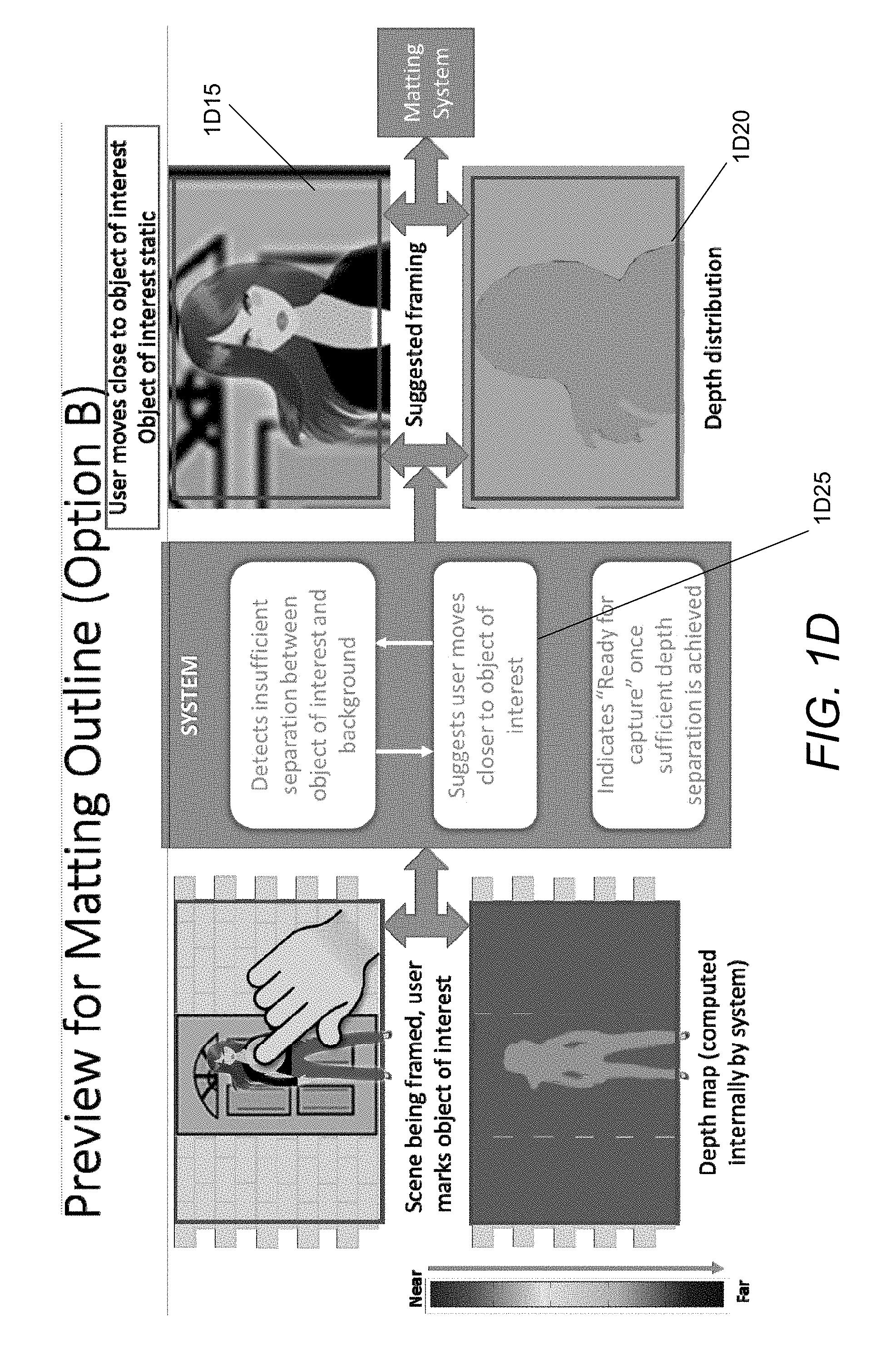
[0075] Another example of a preview for image matting in accordance with an embodiment of the invention is illustrated in FIG. 1D. Like the example illustrated in FIG. 1C, the image matting system has detected an insufficient separation between the foreground object of interest (i.e., person) and the background (i.e., wall/door). In this example, the image matting system suggests 1D25 that the user (i.e., camera) move closer to the object of interest and that the object of interest remain static. As illustrated by the new captured image 1D15 and the new depth map 1D20, there is an increase depth distribution between the foreground object of interest (illustrated as orange in the depth map) and the background (illustrated as bright green in the depth map).
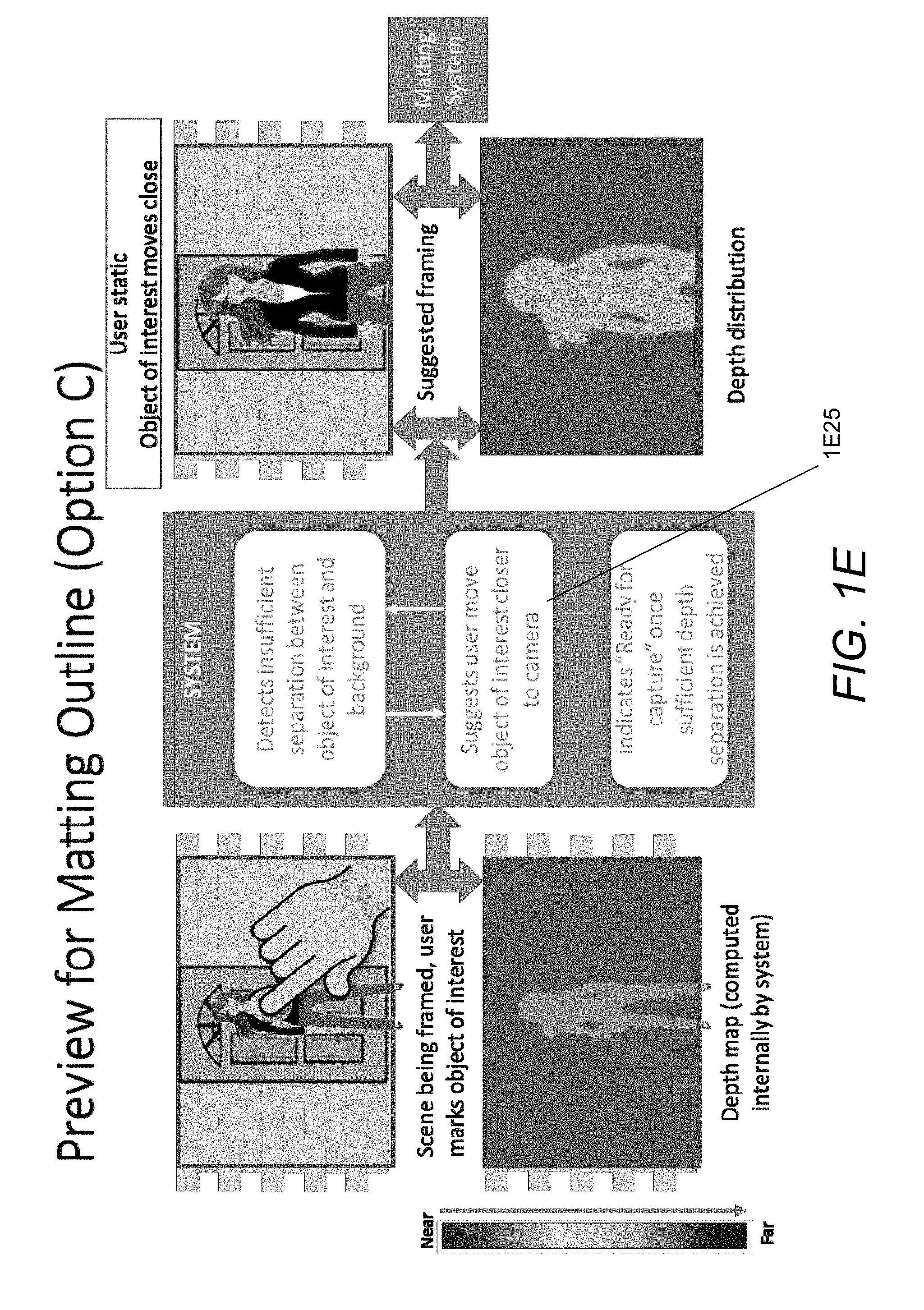
[0076] Yet another example of a preview for image matting in accordance with an embodiment of the invention is illustrated in FIG. 1E. In this example, the notification 1E25 suggests that the user remain static and the object of interest (i.e., person) move closer to the user (i.e., camera). This allows for a sufficient depth separation for image matting.
[0077] Although FIGS. 1C-1E illustrate several examples of preview for image matting, many different preview matting and/or notifications may be implemented as appropriate to the requirements of specific applications and/or scene content in accordance with embodiments of the invention. The use of depth regularization for image matting in accordance with embodiments of the invention is described further below.
Introduction to Image Matting with RGB-D Images
[0078] As described above, recent developments have made it easier to acquire RGB-D images with scene depth information D in addition to pixel RGB color. Examples of devices that may capture depth information include time-of-flight depth cameras, camera arrays, depth from light-field cameras and depth from sensors (e.g., Kinect). These developments provide for new opportunities for computer vision applications that utilize RGB-D images. However, the initial sparse depth is typically coarse and may only be available in sparse locations such as image and texture edges for stereo-based methods. Thus, in order to allow for image matting using the depth information, in some embodiments, the initial sparse depth may be regularized into a dense depth map. During the depth map regularization, some embodiments detect and correct depth bleeding across edges.
[0079] Accordingly, many embodiments provide for depth regularization and semi-automatic interactive alpha-matting of RGB-D images. In several embodiments, a compact form-factor camera array with multi-view stereo is utilized for depth acquisition. Certain embodiments may use high quality color images captured via an additional camera(s) that are registered with the depth map to create an RGB-D image. Although RGB-D images captured using array cameras are described above, image matting using image depth information provided by many different types of depth sensors may be used as appropriate to the requirements of specific application in accordance with embodiments of the invention.
[0080] As described above, many embodiments of the image matting system leverage a Laplacian-based matting framework, with the recent K Nearest Neighbors ("kNN")matting approach disclosed in Chen et al. "Knn Matting", IEEE Conference on Computer Vision and Pattern Recognition (CVPR), pp. 869-876, (2012), ("the Chen et al. 2012 paper") the relevant disclosure from which is incorporated by reference herein in its entirety, to build the Laplacian in order to regularize the initial sparse depth map into a dense depth map for image matting. Some embodiments enable semi-automatic interactive matting with RGB-D images by making the following contributions described in more detail below: (1) dense depth regularization and matting within a unified Laplacian framework, and also use of the Laplacian residual to correct input depth errors; (2) the use of the dense depth segmentation for automatic detailed trimap generation from very sparse user input (a single stroke for foreground and/or background); (3) the use of face detectors to avoid user input entirely of some embodiments; and (4) efficient interactive color matting by incrementally solving a reduced linear system.
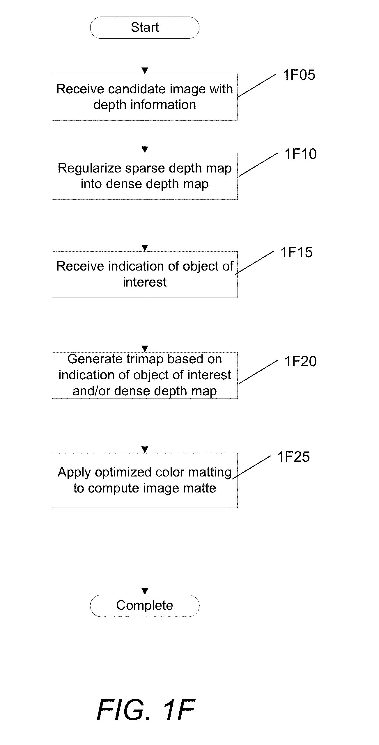
[0081] A process for depth regularization and semiautomatic interactive matting using color and/or depth information of images for image matting in accordance with an embodiment of the invention is illustrated in FIG. 1F.
[0082] The process receives (at 1F05) a candidate image that includes depth information. In some embodiments the image is an RGB-D (i.e., a red, green, blue image with an initial sparse depth map) image. In other embodiments, the image may be defined according to a different color model.
[0083] The process regularizes (at 1F10) the initial sparse depth map into a dense depth map. As described in detail below, the regularization process of some embodiments may include using Laplacian framework to compute depth values and using the Laplacian residual to correct input depth bleeding across image edges.
[0084] The process receives (at 1F15) an indication of an object of interest to be extracted by the image matting system. In some embodiments, the indication of an object of interest may be received from a user input identifying the object of interest, foreground, and/or background portions of the image. In some embodiments, the process may receive a single user stroke of foreground and the process may automatically identify the foreground and/or background layers based on the stroke. In certain embodiments, the user input may be a single stroke on the foreground and a single stroke on the background for image matting. In certain embodiments, object recognition processes, such as (but not limited to) face recognition, may be used to automatically identify an object of interest.
[0085] The process can generate (at 1F20) a trimap with a thin uncertain zone based on the indicated foreground object of interest and/or the dense depth map. In particular, in some embodiments, the process computes the average depth of the regions under the indicated foreground and/or background and segments based on depth into parts closer to the foreground depth and/or background depth. The process then automatically generates the thin trimap by dilating the boundary between foreground and background for the unknown regions. In some embodiments, the process may continue to receive user inputs (e.g., user strokes) indicative of foreground and/or background regions of the image, and the process may continue to refine the initial trimap. This may occur when the process omits parts of the object of interest (e.g., foreground object) and the user may provide more hints as to the foreground object of interest.
[0086] The process can apply (at 1F25) optimized color matting to compute the image matte. As will be described in detail below, in some embodiments, the process may apply a conventional kNN-based (K nearest-neighbor) Laplacian color matting based on the color values of the image, with the Laplacian matting optimized to solve for alpha values in only the unknown regions of the trimap. In the illustrated embodiment, the process then completes.
[0087] Although specific processes are described above with respect to FIG. 1F with respect to depth regularization and semiautomatic interactive image matting using color and depth information for an image, any of a variety of processes can be utilized for depth regularization as appropriate to the requirements of specific applications in accordance with embodiments of the invention.
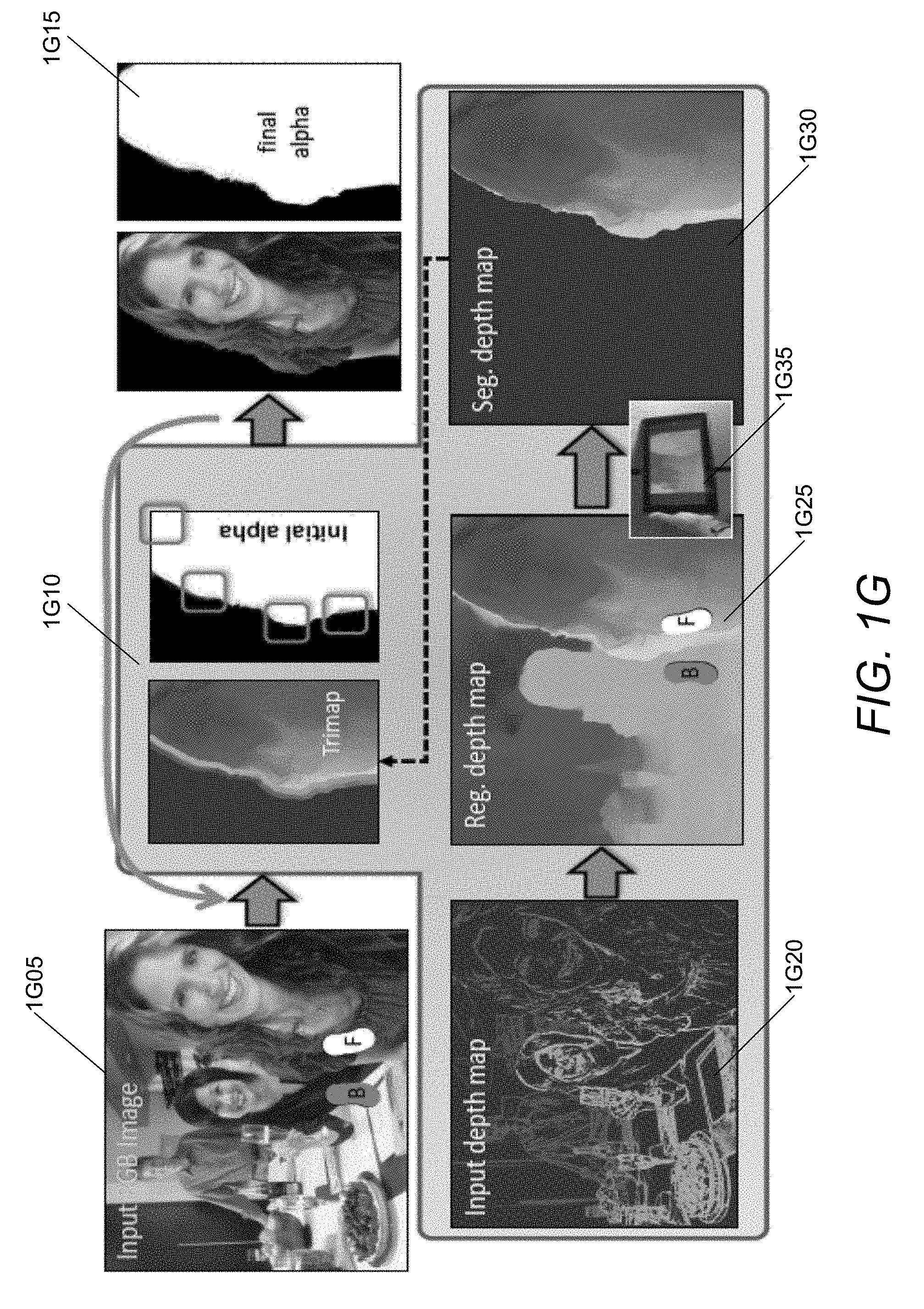
[0088] An example of the image matting pipeline for semi-automatic interactive RGB-D matting in accordance with an embodiment of the invention is illustrated in FIG. 1G. As illustrated, given an input image 1G05 with a single user stroke or blob to identify foreground (F) and background (B), the image matting system produces an alpha matte 1G15. The image matting system can automatically create a thin trimap 1G10 that can also be interactively modified (e.g., to correct it slightly near the arm and shoulder, marked by squares). The bottom row shows the input depth map 1G20 and the regularized dense depth map 1G25 that can be utilized to perform depth-based segmentation 1G30, that can be dilated to create the trimap 1G10. In some embodiments, the RGB-D image may be captured on a tablet equipped with a miniature array camera 1G35. In other embodiments, any of a variety of camera architectures including (but not limited to) an array incorporating a sub-array dedicated to depth sensing and a separate camera(s) dedicated to capturing texture (e.g. RGB) data and/or an active depth sensor can be utilized as appropriate to the requirements of specific applications.
[0089] In some embodiments of the image matting system, essentially the same machinery as Laplacian-matting may be used for depth regularization. This enables an efficient unified framework for depth computation and matting. Some embodiments also provide a novel approach of using the Laplacian residual to correct input depth bleeding across image edges. In ,many embodiments, the dense depth may also be used for other tasks, such as image-based rendering.
[0090] In several embodiments, the image matting system may receive a single stroke on the foreground and/or background to identify the foreground object that is to be extracted during image matting. During image matting, the image matting system can compute the average depth of the regions under one or both strokes (i.e,. foreground and background), and the image matting system may do a quick segmentation based on depth, into parts closer to the foreground or background depth. In some embodiments, the image matting system can automatically create a thin trimap for image matting, by dilating the boundary between foreground and background for the unknown regions. Thereafter, the image matting system may apply a kNN-based Laplacian color matting in the conventional way, but with certain optimizations described in detail below, based on the color image only (since colors typically have greater precision at object boundaries in the image than the regularized depth).
[0091] Some embodiments of the image matting system provide an optimization to conventional Laplacian color matting that makes it one to two orders of magnitude more efficient without any loss in quality. In particular, in some embodiments, instead of solving for alpha values over the entire image and treating the user-provided trimap as a soft constraint with high weight, the image matting system solves a reduced linear system for alpha values only in the unknown regions and no constraint weight is needed. Moreover, by starting the linear solver at the previous solution, the image matting system may incrementally update a matte efficiently. Thus, the user can interactively modify or correct the automatic trimap with real-time feedback.
Related Work--Alpha Matting
[0092] Laplacian matting is a popular framework. Methods like local and non-local smooth priors ("LNSP") matting build on this, achieving somewhat higher performance on the Alpha Matting benchmark by combining nonlocal and local priors. A few matting systems are interactive, but typically must make compromises in quality. Other methods are specialized to inputs from array cameras but do not apply to general RGB-D images, or demonstrate quality comparable to state of the art color matting.
[0093] Accordingly, image matting systems in accordance with many embodiments of the invention can provide for making semi-automatic and interactive, Laplacian matting methods on RGB-D images and also enable depth regularization in a unified framework.
Background of Affinity Based Matting
[0094] Described below is a brief review of Affinity-Matrix based matting. These methods typically involve construction of a Laplacian matrix. Some embodiments use this approach for its simplicity and high-quality. However, processes in accordance with several embodiments of the invention perform certain optimizations, and use the framework as the basic building block for both depth regularization and matting.
[0095] In convention matting, a color image is assumed to be generated as I=.alpha.F+(1-.alpha.)B, where I is the image, .alpha. is the matte, between 0 and 1, and F and B are the foreground and backgrounds layers. .alpha. is a number, while I, F and B are RGB intensity values (or intensity values in another appropriate color space).
[0096] The Laplacian L=D-A, where A is the affinity matrix (methods to construct A are discussed at the end of the section). D is a diagonal matrix, usually set to the row sum of A. The idea is that alpha at a pixel is an affine combination of close-by alpha values, guided by A. Some embodiments define x as a large (size of image) vector of alpha or matte values (between 0 and 1). Ideally, some embodiments provide that:
x i = j A ij x j j A ij D ii x i = j A ij x j ( 1 ) ##EQU00001##
where the diagonal matrix D is the row sum, such that D.sub.ii=.SIGMA..sub.jA.sub.ij.
[0097] Succinctly,
Lx.apprxeq.0 (2)
[0098] Since L=D-A and D is a diagonal matrix. However, solving this equation without any additional constraints is largely meaningless; for example x=x.sub.0 for any constant x.sub.0 is a solution. Therefore, Laplacian-matting systems solve:
x=arg min x.sup.TLx+.lamda.(x-y).sup.TC(x-y), (3)
where the first term optimizes for the constraint that Lx=0, and the second term enforces user constraints in a soft way, with .lamda. a user-defined parameter, y being the user-marked known region (either 0 or 1) and C being a diagonal confidence matrix (that will usually have entries of 1 for known or 0 for unknown).
[0099] The solution to this optimization problem (minimization) is:
(L+.lamda.C)x=.lamda.Cy, (4)
which can be viewed as a sum of constraints Lx=0 and Cx=Cy. This equation (6) is usually solved using preconditioned conjugate gradient descent.
[0100] Several methods have been proposed to generate the affinity matrix including the procedures described in Levin et al. "A Closed Form Solution To Natural Image Matting," IEEE Conference on Computer Vision and Pattern Recognition (CVPR), vol. 1, pages 61-68, (2006), the disclosure of which is hereby incorporated by reference in its entirety, uses the color lines model to look for neighboring pixels. Some embodiments use the kNN-method described in the Chen et al. 2012 paper. First, a feature vector may be computed for each pixel in the image, usually a combination of pixel color and scaled spatial location that may be referred to as RGBxy. Some embodiments may also use the regularized depth estimates as the feature vector, that is, the feature vector can be RGBDxy. A kd-tree may be constructed using this array of features. For each pixel (row), n nearest neighbors may be found by searching the kd-tree, and may be assigned affinity scores (mapped to the range [0, 1] based on distance in feature space). Several other methods, do not use the affinity matrix explicitly; however, one can think of them in the affinity matrix framework.
Depth Regularization
[0101] In many embodiments, before the initial sparse depth map may be usable for image matting, it may be regularized into a dense depth map. Some embodiments provide a novel matting-Laplacian based process to create the dense depth map. In particular, an unknown depth may be approximately an affine combination of depths at "nearby" pixels, just as the alpha value is in color matting, and there may be a strong correlation between image and depth discontinuities. Some embodiments thus are able to precompute the Laplacian once while creating the RGB-D image, and make it available to subsequent applications (see FIG. 6). As described above, in some embodiments, the image matting system handles depth ambiguity that is typical for depth maps obtained through multi-view stereo.
[0102] As noted above, depth map maps can be obtained using multi-view stereo (MVS) to generate the dense depth map. Other embodiments may use other depth acquisition devices with different characteristics, such as the Kinect depth sensor distributed by Microsoft Corporation of Redmond, Wash., and 3D light field cameras distributed by Raytrix GmbH of Kiel, Germany, as illustrated in the example in FIG. 5 to obtain the initial sparse depth map.
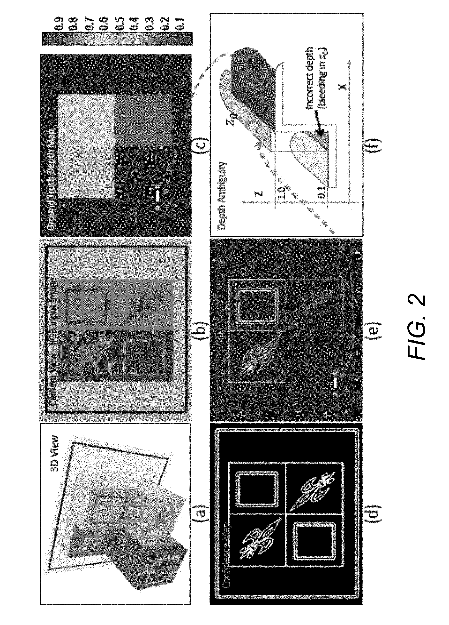
[0103] In some embodiments, the inputs to the image matting system may be a high resolution RGB image I with m.times.n pixels, and an indexed depth map z.sub.0. In the image matting system, z.sub.0 may correspond essentially to disparity, with higher z indicating greater disparity. Some embodiments may also use a binary confidence map C that indicates whether the depth at a given pixel is confident. Some embodiments may obtain C by a thresholded gradient of the intensity of the input image I, since stereo depth is generally accurate at image and texture edges. FIGS. 2-4 show synthetic (simulated) and real example outputs of the sensor.
[0104] In a number of embodiments, since the confidence map may be defined only at edges, the depth map reported may span ("bleeds" across) an edge, as shown for simple synthetic data in FIG. 2(c,f). In particular, FIG. 2 illustrates an example of a simple synthetic scene (5 depth planes). FIG. 2(a) illustrates a 3D view of the scene. FIG. 2(b) illustrates the color image. FIG. 2(c) illustrates ground truth depth map (disparity) z.sub.0* shown in false color (normalized). FIG. 2(d) illustrates the confidence map C where the depth is available (simulated), mainly at texture and object edges. FIG. 2(e) illustrates bleeding edge depth z.sub.0 reported by the sensor (simulated). FIG. 2(f) shows a sectional view of the 3D scene along a cutting plane p-q marked in FIG. 2(c) and FIG. 2(e). Bleeding depth is shown along the profile indicated by the white line segment.
[0105] In FIG. 2, 14% of the pixels are confident, 11.2% because of surface texture gradients and 2.8% from depth at edges. Of these 2.8%, half (1.4%) are the correct depth (interior of foreground object) while the other half (1.4%) are incorrect depth (bleeding), assigning foreground depth on the background object. When there is a geometric discontinuity, it is difficult to determine which side of the surface the depth really belongs to. This is a fundamental limitation. However, the depth may belong to the closer foreground layer with greater disparity, whichever side that happens to be.
Depth Regularization in Laplacian Framework
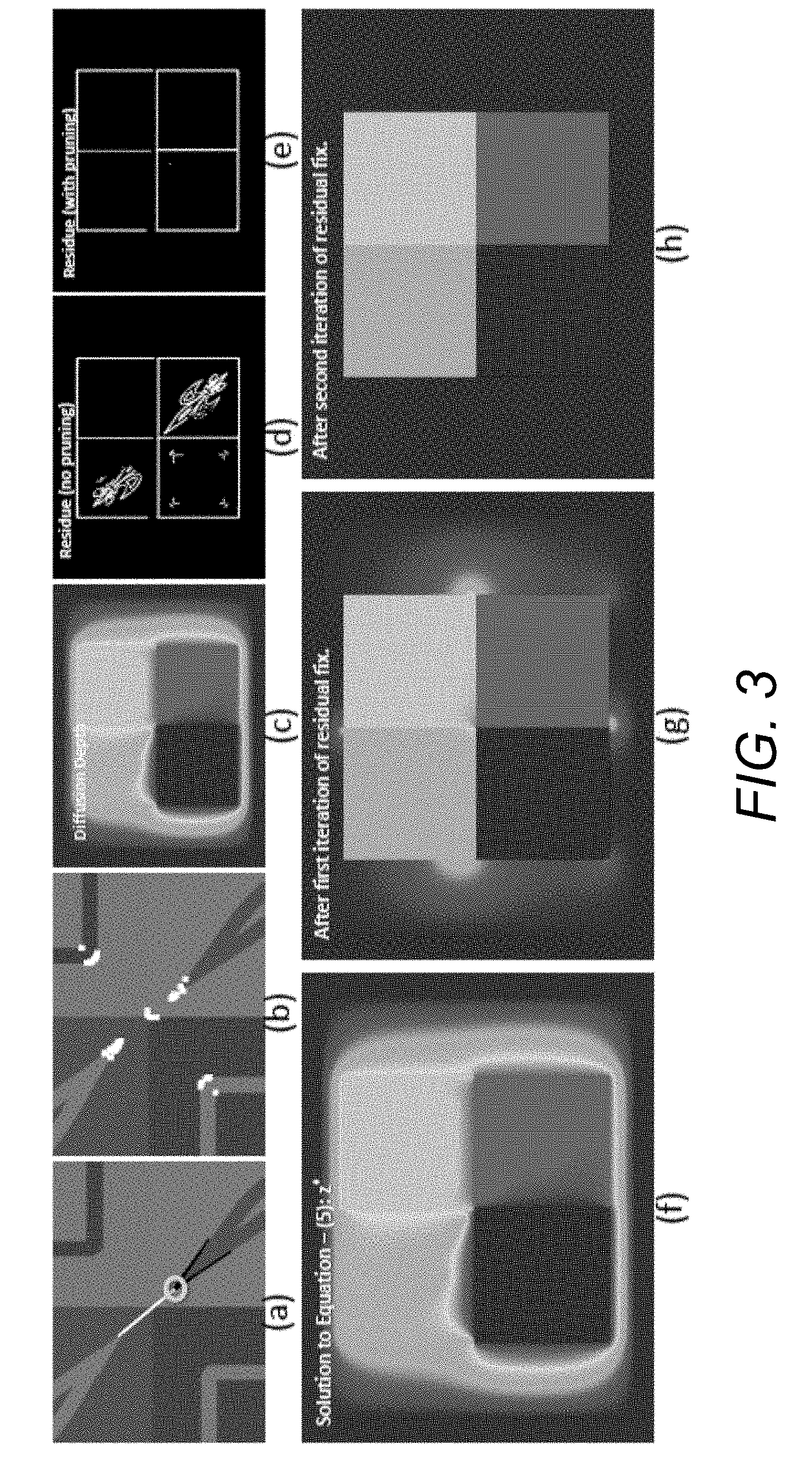
[0106] An example of Laplacian pruning and residual correction in accordance with an embodiment of the invention is illustrated in FIG. 3. The synthetic scene is from FIG. 2. FIG. (A) illustrates incorrect connection. The white line indicates the pixel highlighted by a circle is connected to another similar pixel from a different depth group. Black lines indicate acceptable connections. (B) highlights more pixels with "bad" connections. (C) illustrates diffusion depth map z.sub.D. (D) illustrates Laplacian residual R without Laplacian pruning, that is retaining all the connections shown in (A). (E) illustrates residue R after Laplacian pruning. (F) illustrates regularized depth map z*. (G) illustrates regularized depth map after first iteration of residue correction. (H) illustrates regularized depth map after second pass of residue correction.
[0107] As described above, some embodiments perform depth regularization using the Laplacian L and the data term z.sub.0 weighed by confidence map C. For mathematical convenience, some embodiments treat C as a sparse mn.times.mn diagonal matrix, whose diagonal entries are the binary confidence values. The regularized depth z* with reference to a given C can be computed through an optimization process similar to equations 3, 4 as:
z * = argmin z ( z T Lz + .lamda. ( z - z 0 ) T C ( z - z 0 ) ) ( L + .lamda. C ) z * = .lamda. Cz 0 ( 5 ) ##EQU00002##
[0108] An example of z* in accordance with an embodiment of the invention is illustrated in FIG. 3f. As illustrated, the very sparse depth at edges of the initial depth map has been regularized into a dense depth map everywhere in the image. However, the depth edges are smeared, which can be attributed to incorrect bleeding of input depth. The remainder of this sub-section addresses this issue by (1) pruning the Laplacian to avoid incorrect non-local affinity matches across depth boundaries, and (2) exploiting Laplacian residuals to detect and correct bleeding of input depths. The final result in FIG. 3(h) is much more precise.
[0109] As described above, some embodiments use the kNN approach which may pair similar pixels without regards to their depth, when constructing the affinity matrix A and Laplacian L. Two nearby color-wise similar pixels may be at two different depths (FIGS. 3(a,b)). Such non-local pairings can be beneficial to matte extraction. However, they can also cause issues in some cases for depth regularization, and unexpected results during matting if foreground and background objects have similar colors. Ideally, for each pair (i,j) corresponding to a nonzero entry in A.sub.ij, some embodiments test if i and j have depth differences beyond a threshold. However, detecting and pruning such pairs is a chicken-and-egg challenge, since depth is needed to do the pruning, but depth is obtained by using the original Laplacian. Therefore, some embodiments may first find an approximate dense depth map through a diffusion process,
(L.sub.D+.lamda.C)z.sub.D=.lamda.Cz.sub.0 (6)
where L.sub.D is the diffusion Laplacian constructed such that each pixel may be connected to 8 of its surrounding neighbors (using only spatial proximity, not RGB color values). A result is shown in FIG. 3(c). Using z.sub.D, some embodiments may compute the depth difference for each pair (i,j) as |z.sub.D(i)-z.sub.D(j)|. If this difference is above a certain threshold, some embodiments purge those pairs by assigning A.sub.ij=0. While pruning, some embodiments ensure a minimum number of connections are retained.
[0110] Processes in accordance with certain embodiments of the invention provide a novel approach to detect and correct depth bleeding across edges. The key insight is that solving equation 5 above, the basic Laplacian condition in equation 2, namely that Lz*.apprxeq.0 should also be satisfied. In some embodiments, after solving for z*, it is easy to compute the Laplacian residual,
R=Lz* (7)
[0111] As shown in the example illustrated in FIG. 3(d), the residual R is close to 0 in most regions--those pixels have depth or disparity well represented as an affine combination of values at nearby pixels. However, there are regions involving connections across different depths, with large residuals. The pruning discussed above resolves most of these issues (FIG. 3(e)), but there are still regions along depth edges where |R| is large. This residue indicates a disagreement between the Laplacian prior and the data term. It indicates the data term is enforcing an incorrect depth value.
[0112] Some embodiments seek to find and remove depth edges that have "bled" over to the wrong side. Some embodiments observe that confident depth may always belong to the foreground layer. Since z represents disparity in some embodiments, the z value (disparity) of foreground should be greater than that of background. For example, consider a pixel that should have background depth, but is incorrectly given confident foreground depth (FIG. 2(c,f)). After regularization, this pixel may have higher disparity z* than the average of its neighbors (which will include both foreground and background disparity values). The Laplacian L=D-A, and the residual R=Lz*-Az*. This is effectively the value at z* minus the average of its neighbors (connected through the affinity matrix). Since disparity z* is higher than its neighbors, incorrect confident depths can be identified as those regions where R>0.
[0113] A new confidence map can be computed and set C.sub.i=0 at pixel i whenever R.sub.1>.tau., leaving C unchanged otherwise (for example using an appropriate value such as, but not limited to, .tau.=0.005). In several embodiments, the process may iterate by solving equation 5 with the new confidence map, starting with the previous solution (compare FIGS. 3(f,g)). Results in this section are presented with two iterations found as adequate. Although, as can readily be appreciated, any number of iterations can be performed as appropriate to the requirements of a specific application. FIG. 3(h) shows the result in the synthetic case, that is much more accurate than without the residual correction.
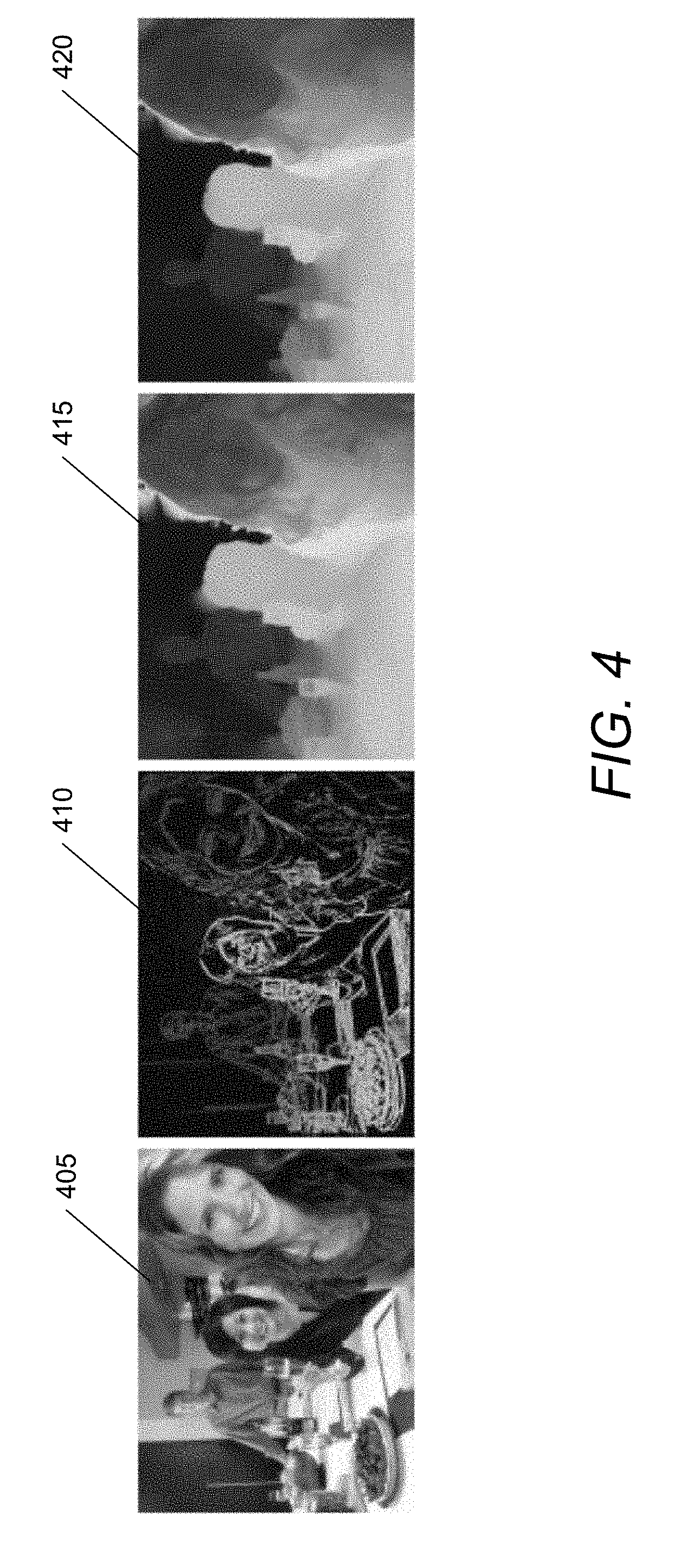
[0114] An example of image matting on a real scene in accordance with an embodiment of the invention is illustrated in FIG. 4. In particular, FIG. 4 illustrates an RGB image 405 produced from an array camera, initial sparse depth map 410 from multiview stereo at edges and texture boundaries, initial regularized depth map with bleeding 415, and final regularized depth map 420 after Laplacian residual correction. As illustrated in this example, the initial sparse depth map from the sensor is regularized into a high quality dense depth map, with Laplacian residual correction improving the results further.
Comparison and Generality:
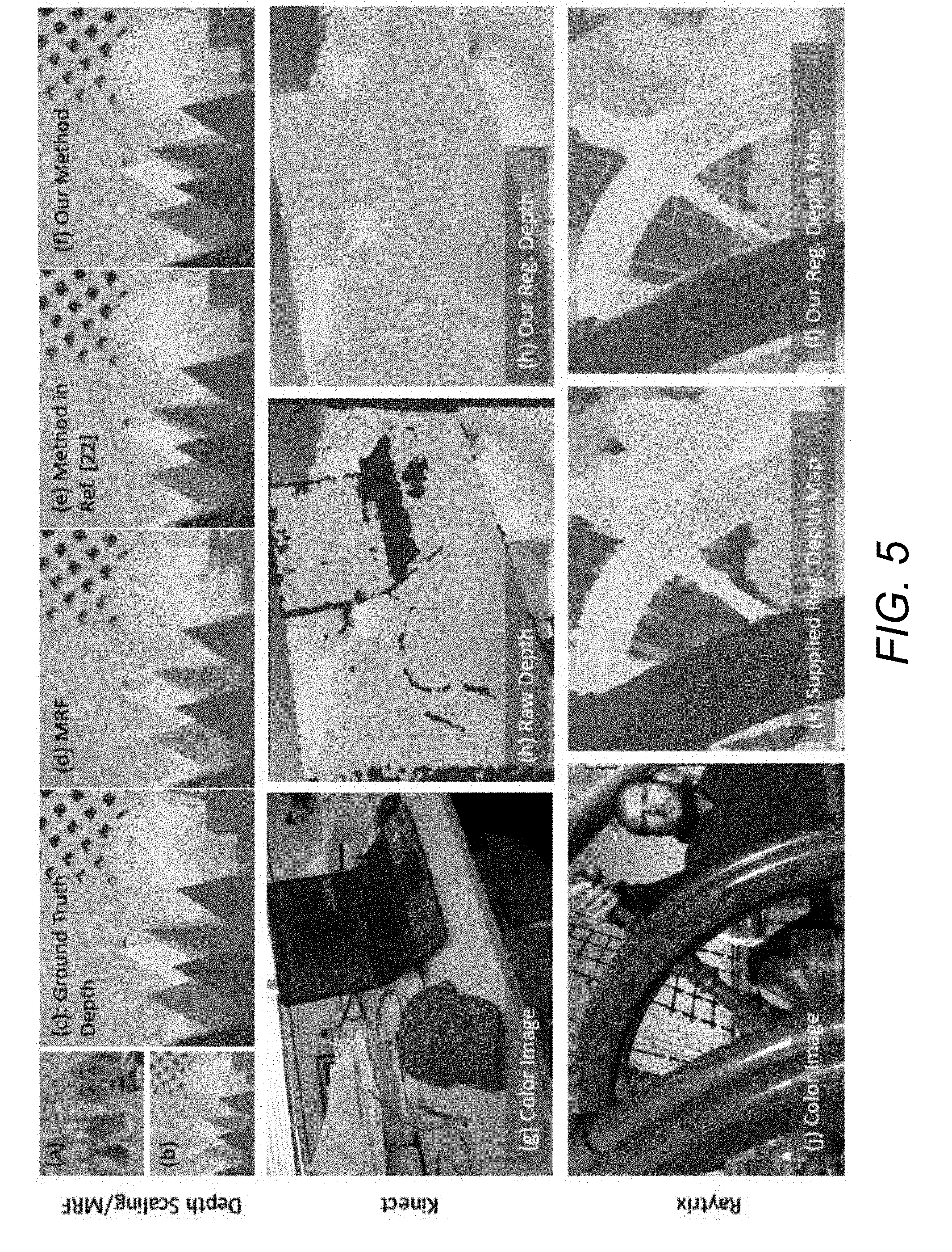
[0115] FIG. 5 shows the generality of the approach to other RGB-D systems, and compares against other methods. In all cases, it can be seen that the depth from an embodiment of the image matting system is sharper and more complete. In particular, FIG. 5 illustrates the results of depth regularization processes performed on depth maps generated by various types of depth sensing technologies and provides a comparison. The top row (a-f) provide a comparison of the image matting system to Markov Random Field (MRF) and the method described in Tallon et al., "Upsampling and Denoising of Depth Maps Via Joint-Segmentation," 20.sup.th European Signal Processing Conference (EUSIPCO), pp. 245-249 (2012), (the "Tallon et al. paper"), the relevant disclosure of which is hereby incorporated by reference in its entirety. (A) illustrates an input color image. (B) illustrates 1/8 scaled and noisy version of the ground truth depth map (c). (D) is the recovered upscaled depth map using MRF. (E)is the method in the Tallon et al. paper. (F) is an embodiment of the image matting system method that produces a depth map closer to the ground truth. The middle row (g-h) compare with Kinect images. (G) is the colored image, (h) is the Kinect depth map that has holes, (i) is the sharper and more complete version after regularization. Bottom row(j-1) compare with Raytrix images. The color image from one view is in (j). Their regularized depth map in (k) has more spurious depths and bleeding than the sharper result from an embodiment of regularization of the image matting system in (l).
[0116] To compare to MRF, source images and results from the method described in the Tallon et al. paper are used. Here, a known ground truth image is downsized to 1/8 its original size and noise is added. The Tallon et al. paper proposes a method to upscale the depth map using the original color image as prior, and also performs comparison to MRFs. The comparison started with the same downsized image, upscaled it, and regularized the depth map. Accordingly, this produces a depth map with less noise, and the edges are well defined, resembling the ground truth, as shown in FIG. 5-(top row).
[0117] Next, an RGB-D image from the Kinect sensor (depth map warped to color image) using the method disclosed in Lai et al. "A large-scale hierarchical multi-view RGB-D object dataset," Proc. IEEE International Conference on Robotics and Automation (ICRA), pp. 1817-1824 (2011), the relevant disclosure of which is herein incorporated by reference in its entirety, is considered. Due to warping errors and occlusions, the input depth map has holes and misalignment. In several embodiments, the image matting system may fill 1 in the missing values (confidence map is set to 1 when the depth is known) and may also align the depth map to the color image. In this case, residue correction (confidence set to 0) is performed wherever the absolute value of the Laplacian residual |R| is greater than a threshold. These regions essentially indicate incorrect alignment of depth. The result is shown in FIG. 5-(middle row).
[0118] Regularization was also performed on a sparse depth image captured with the Raytrix light field camera as disclosed in Perwass et al., "Single Lens 3D-Camera with Extended Depth-of-Field," SPIE 8291, 29-36, (2012), the relevant disclosure from which is hereby incorporated by reference in its entirety. A confidence map was generated based on the Raytrix depth map (wherever the depth is available, which is clustered around textured areas). The resulting regularized depth map shows a lot more depth detail, compared to the Raytrix regularization method, as seen in FIG. 5-(bottom row). However, a few outliers in are observed in the resulting regularized depth map due to a lack of access to the noise model of the input depth map, and the noisy input depth.
[0119] Various application of regularized depth maps in accordance with various embodiments of the invention are illustrated in FIG. 6. The left three images show examples of changing view-point as in image-based rendering, as well as the 3D mesh obtained simply by connecting neighboring pixels (foreground/background connections are not prevented). The right two images show refocusing on the foreground object with a simulated large aperture, and a visual effect obtained by making the light intensity fall off with depth from the camera.
Efficiency Optimizations
[0120] Performing depth regularization in large flat areas may involve redundant computation. Accordingly, in order to speed-up processing, an image can be broken into super-pixels, where the size of a super-pixel is a function of the texture content in the underlying image. For example, processes in accordance with several embodiments of the invention use a quad-tree structure, starting with an entire image as a single super-pixel and sub-divide each super-pixel into four roughly equal parts if the variance of pixel intensities within the initial super-pixel is larger than a certain threshold. This may be done recursively with the stopping criteria being: until either the variance in each super-pixel is lower than the predetermined threshold, or the number of pixels in the super-pixel is lower than a chosen number.
[0121] In some embodiments, each super-pixel can be denoted by a single feature vector. For example, RGBxy or RGBxyz feature of the centroid of each super-pixel. This process may significantly reduce the number of unknowns for images that have large texture-less regions, thus allowing the image matting system to solve a reduced system of equations.
[0122] After performing regularization on the superpixels, an interpolation can be performed to achieve smoothness at the seams of superpixels. In particular, to smoothen this out, each uncertain (unknown) pixel's depth can be estimated as a weighted average of the depths of the k-nearest super-pixels. In some embodiments, the weights may be derived as a function of the distance of the RGBxy (or RGBxyz) feature of the pixel from the super-pixel centroids.
[0123] The speedup factor can be roughly linear in the percentage of pixel reduction. For example, with superpixels equal to 10% of the original image pixels, a speed up of an order of magnitude is obtained, and the regularized depths can be accurate to within 2-5%.
Automatic Trimap Generation
[0124] In some embodiments, an initial step in matting processes may be to create a trimap. In several embodiments, the trimap includes user-marked known foreground and background regions, and the unknown region. While methods like kNN matting can work with a coarse trimap or sparse strokes, they usually produce high quality results only when given a detailed thin trimap. Creating such a trimap often involves significant user effort. Accordingly, some embodiments provide a semi-automatic solution by providing that RGB-D images enable separation of foreground and background based on depth. However, in a number of embodiments, the depth may be less precise at boundaries than the color image, even with the Laplacian-residue adjustments described above. Accordingly, some embodiments may use the depth to automatically create a detailed thin trimap from sparse user strokes, followed by color matting. Note that this is not possible with RGB only images.
[0125] As described above, FIG. 1 illustrates the overall pipeline for semi-automatic interactive RGB-D matting. As illustrated in the example in FIG. 1, the user may draw a single foreground and a single background stroke or blob. In another embodiment, the user may only select the object of interest in the scene. This object need not necessarily be the foreground (or foremost) object in the scene. The image matting system in some embodiments analyzes the user stroke, along with the distribution of objects (in 3D, i.e., including depth) in the scene and automatically suggests a depth range so as to separate the object of interest from the rest of the scene. In some embodiments, the image matting system does so by analyzing the depth histogram of the image. If a multimodal distribution is found, the image matting system attempts to estimate thresholds to segregate the mode containing the depth of the object of interest from the rest of the depth distribution.
[0126] If multiple objects lie in the same depth range, the image matting system may also automatically limit the selection to a single object by analyzing depth discontinuities. If an incorrect selection is made, the user may have the option to provide active inputs (e.g., marking regions to be region of interest or not), whereby the image matting system may refine the initial identification of the object of interest from multiple inputs.
[0127] In many embodiments, the image matting system may analyze depths within only a window around the object of interest. The trimap may be enforced globally (that is, to the entire scene), locally (only in the window selected, the window may be resizable by the user) or by an object segmentation process whereby the object of interest is identified in the entire image based on the threshold selected from the user input.
[0128] In several embodiments, the image matting system computes the average depth in the foreground versus background strokes, and simply classifies pixels based on the depth to which they are closest. As shown in FIG. 1, this may provide a good segmentation, but may not be perfect at the boundaries. Therefore, some embodiments use edge detection, and apply standard image dilation on the boundaries to create the unknown part of the trimap (FIG. 1 top row).
[0129] Many different alternatives may be possible for semi-automatic or automatic matting. In a number of embodiments, the user could simply draw a box around the region of interest. Alternatively, the image matting system could use a face detector and/or other types of automatic object detectors and automatically create the box, as illustrated in an example in FIG. 7, where the front person is matted from the background completely automatically. In particular, FIG. 7 illustrates an example of fully automatic RGB-D matting using a face detector in accordance with an embodiment of the invention. FIG. 7 illustrates the input image 705 with face detection. The image matting system creates a thin trimap 710 from which the alpha matte 715 is automatically computed. As illustrated, the insert in the alpha matte 715 shows using the same blobs for RGB-only matting; without depth information, the quality is much worse.
[0130] In some embodiments, the foreground and background blobs may be automatically computed as circles within the two largest boxes from the face detector. In certain embodiments, a comparison can be performed with simple RGB only matting, using the same foreground/background blobs (alpha inset in third sub-figure). Accordingly, the RGB-D image may be used for detailed trimap creation and high quality mattes.
Using Occlusion and Visibilty Information
[0131] As described above, initial sparse depth maps from camera arrays may be obtained through disparity estimation (e.g., parallax processing) and typically yield high confidence depth values for textured regions. As part of the disparity estimation process in the camera array pipeline, it is easy to identify regions containing occlusions, which are regions that are adjacent to foreground objects that are occluded by the foreground object to some of the cameras in the array. These occluded regions may be easily identified in the disparity estimation step and potentially seed the trimap that is needed for the start of the color image matting stage. This enables a reduction in the user inputs to the matting process resulting in an improved user experience
Efficient Interactive Laplacian Color Matting
[0132] In some embodiments, after trimap extraction, Laplacian color matting is employed to compute the matte, and extract foreground/background colors if desired. Reduced matting equations can be used that solve for alpha only in the unknown regions of the trimap, with a speedup proportional to the ratio of the full image to the unknown part of the trimap. In several embodiments, since the automatic trimap may have a thin unknown region, efficiencies of one to two orders of magnitude may be achieved, providing interactive frame rates without any loss in quality. Moreover, in a number of embodiments, the exact Laplacian equation can be solved for, without an arbitrary parameter .lamda. to enforce user-defined constraints (that by definition are now met exactly in the known regions). In certain embodiments, this method is very simple and may extend easily to incremental matting where interactive edits are made to the trimap, with real-time updates of the matte. Furthermore, as described above, some embodiments may use the interactive guided image capture for image matting.
Computational Considerations and Reduced Matting
[0133] In general, the conventional matting formulation wastes considerable effort in trying to enforce and trade-off the Laplacian constraint even for pixel values in the known regions of the trimap. Instead, some embodiments solve for the constraint only at pixels marked unknown in the trimap. In other words, these embodiments directly solve equation 2 for unknown pixels. Accordingly, this provides a much simpler system, with no parameter .lamda.. Furthermore, the image matting system is no longer under-constrained, since the unknown pixels will have neighbors that are known, and this may provide constraints that lead to a unique solution. More formally, these embodiments use superscripts u to denote unknown pixels f for foreground pixels and b for background. The pixels can be conceptually re-ordered for simplicity, so that equation 2 can be written as
( L uu L uf L ub L uf L ff L fb L ub L fb L bb ) ( x u x f x b ) = 0 ( 8 ) ##EQU00003##
[0134] So far, this is simply rewriting equation 2. In some embodiments, the image matting system may now restrict the Laplacian and solve only for the rows corresponding to the unknown pixels. Unlike in the standard formulation, these embodiments may simply leave known pixels unchanged, and do not consider the corresponding rows in the Laplacian. Accordingly, in some embodiments this is rewritten as:
( L uu L uf L ub ) ( x u x f x b ) = 0 ( 9 ) ##EQU00004##
[0135] Several embodiments can do this, in a modified form, for depth regularization. This may be especially useful for images that are well textured and regularization is only needed for a small percentage of pixels that are marked as non-confident. The formulation is as follows:
( L uu L uk ) ( x u x k ) = 0 ( 9 B ) ##EQU00005##
where L.sup.uk is the Laplacian connections between unknown (not confident) pixel with unknown depth x.sup.u and pixels with known (high confidence) depths annotated by x.sup.k.
[0136] In the above equation (9), some embodiments may now set x.sup.f=1 and x.sup.b=0, to derive
L.sup.uux.sup.u=-L.sup.uf1 (10)
where the right-hand side corresponds to row-sums of L.sup.uf (1 is a column-matrix of 1, of the same size as the number of foreground pixels).
[0137] Note that L.sup.uu is diagonally dominant, since the diagonal elements are row-sums of the full affinity matrix, which is more than the reduced affinity in L.sup.uu. Therefore, the image matting system may have a solution and is in fact usually better conditioned than the original system.
[0138] The computational savings may be considerable, since the image matting system may only need the reduced matrices for the unknown pixels. The Laplacian size is now ur rather than pr, where r is the number of neighbors for each pixel, and u<<p is the number of unknown pixels while p is the total number of pixels. If unknown pixels in the trimap are one-tenth of the image, the image matting system can easily save an order of magnitude in computation with essentially no change in the final image.
[0139] Within an interactive matting system, it may seek to update x in real-time, as the user changes the trimap. A simple approach is to use x from the previous frame as the initial value for preconditioned conjugate gradient. Often, this is close enough to the error tolerance immediately, and usually only one or two iterations are needed, making the incremental cost of an update very fast. As can readily be appreciated, motion tracking can be utilized to accommodate motion of the depth sensor and/or camera relative to the scene.
[0140] Matting also may often involve solving for foreground and background. For kNN-matting, Chen et al., "KNN Matting," IEEE Transactions on Patterm Analysis and Machine Intelligence, Vol. 35, No. 9, September 2013, (the Chen et al. 2013 paper) the relevant disclosure of which is hereby incorporated by reference in its entirety, pose an optimization problem. As described in detail below, with respect to this optimization problem, some embodiments can solve a reduced system, providing considerable speedups for layer extraction.
Accuracy and Quality
[0141] An example of a quality comparison to unoptimzed kNN on a color image (top row) and from an embodiment of the RGB-D data (bottom row) in accordance with an embodiment of the invention is illustrated in FIG. 8. The results (c,g) are almost identical to the full Laplacian solution (b,f). Solving the reduced Laplacian provides a speed benefit without any loss in quality (d,h).
[0142] In particular, FIG. 8 shows two mattes computed with our method, one on the color RGB alpha matting benchmark, and one with an image matting system in accordance with an embodiment of the invention. In both cases, the quality is essentially identical to kNN matting without the speed optimization. For all 20+ images in the alpha matting benchmark, the optimization introduced a difference in the matte of less than 0.1%, with the median being 0.0001.
[0143] An example of timings in accordance with an embodiment of the invention is illustrated in FIG. 9. The graph 905 graphs speedup vs. ratio of total to unknown trimap pixels on the alpha matting benchmark referred to above with respect to FIG. 8. Two trimaps are shown in red and blue circles, and the black line indicates the linear speedup achieved on average. The table 910 on the right illustrates timing for 1000.times.750 RGB-D images captured with the image matting system. Speedups of more than an order of magnitude are achieved, given the image matting system's detailed thin trimaps.
[0144] In particular, FIG. 9 plots 905 the speedup of the optimized method versus standard kNN. The example ran comparisons on all of the standard color only images in the alpha matting benchmark using two trimaps of varying precision (shown as red and blue circles in FIG. 9). The speed-ups are essentially linear (black line), based on the ratio of the number of total pixels to unknown trimap pixels, and obtain a 10x benefit in many cases. FIG. 9 (right) shows the running time and speedup for the final color matting step on a number of RGB-D images captured with the image matting system. Because the image matting system's method automatically creates thin detailed trimaps, speedups are even more impressive, with running times a fraction of a second. In some embodiments, a user may adjust the trimap in real-time using various interactive editing tools as described in detail below.
Interactive Editing
[0145] FIG. 10 illustrates screen shots from an example of an interactive system, that allows the user to adjust the trimap in real-time. In particular, FIG. 10 illustrates an interactive editing of trimaps with real-time feedback on the matte. FIG. 10 illustrates the graphical user interface ("GUI") 1005 and minor touch-ups to specific trimap 1010 regions, illustrated as boxes 1-4 on the trimap, to produce the final high-quality matte 1020. The user simply adds small foreground, background, or unknown strokes 1015 to modify the trimap. Updates to the matte happen in less than 0.1 seconds.
[0146] In particular, the incremental computation happens in real-time, taking an average of 0.1 seconds in Matlab to update after each edit, with between 0 and 5 iterations, starting from the previous solution. In many frames, the previous solution is close enough (using a threshold of 0.001), so no iterations or changes are required. The disclosure below includes more examples of depth regularization and matting using images from an array camera. This disclosure considers various scenes (objects, people, indoor and outdoor) and present timing and performance information.
[0147] In some embodiments, the Laplacian residual may also be applied to image matting, to automatically fix regions that are incorrectly marked in the trimap. Some embodiments may use reduced Laplacians to reduce precompute time, in addition to speeding up run-time. In some embodiments, the image matting system could also be extended to depth estimation and matting in video. In several embodiments, the image matting system may be used in potential applications in mobile devices like phones and tablets, equipped with mobile light field or camera array sensors, among various other devices.
Depth Regularization and Semiautomatic Interactive Matting Using RGB-D Images
[0148] The image matting system of some embodiments may be further optimized using various different optimization techniques, as will be described in detail below. These techniques include an extension to efficient Laplacian color matting to also solve for foreground and background efficiently. In several embodiments, a further efficiency optimization may be performed, as will be described below, that makes a small additional approximation to achieve faster times and eliminate the tradeoff parameter .lamda., as illustrated in the examples in FIG. 11 and FIG. 12.
[0149] In particular FIG. 11 illustrates (a) a color image, (b) ground truth alpha, (c) color image multiplied by alpha, with the blue background bleeding in the fur on the top, (d) foreground multiplied by alpha using kNN took 140 seconds, (e) foreground multiplied by alpha: using reduced system took 3.5 sec (speed up of 40.times.), (f) using faster approximation extraction to compute foreground multiplied by alpha. Took 1.4 sec for a net speed up of 100.times.. The images are almost identical in all cases.
[0150] FIG. 12 illustrates (a) color image multiplied by alpha; see incorrect colors in the top of the hair, (b) kNN-matting, (c) reduced system, (d) fast approximate method. The images are almost identical with two order of magnitude speedups between (d) and (b).
[0151] Finally, FIGS. 13-18 show a number of additional examples of semiautomatic interactive depth-based matting on RGB-D images from a compact array camera, beyond the results described above in accordance with embodiments of the invention. In particular, FIGS. 13-18 showcase a variety of successful examples of automatic trimap generation with minimal user input, and one failure case in FIG. 17.
Efficiently Solving for Foreground and Background
[0152] While the above description primarily focuses on estimation of the alpha value, processes in accordance with many embodiment of the invention also involve solving for the foreground and background regions of images. For kNN-matting, the Chen et al. 2013 paper poses an optimization problem. In this case, the image matting system cannot avoid the optimization, but can solve a reduced system, providing considerable speedups for layer extraction as well. This section first introduces the original formulation of Chen et al. 2013 paper (correcting a minor typographical error in their equations) and then develops the speedup. The next section develops an approximation of some embodiments that may be even faster and does not require optimization.
Optimization Formulation
[0153] The optimization considers two terms: The closeness of foreground and background to their neighbors, and faithfulness to data. The data term can be written as,
min2.lamda..SIGMA..sub.k(.alpha..sub.kF.sub.k+.alpha..sub.kB.sub.k-I.sub- .k).sup.2 (11)
where the subscript k denotes the pixel, and =1-.alpha.. Note that the data term handles each pixel separately, and couples foreground and background. Setting the derivative with respect to F.sub.k and B.sub.k to zero separately, and omitting the constant factor of 4 (that is also present in the proximity term), to obtain:
.alpha..sub.k.sup.2F.sub.k+.alpha..sub.k.alpha..sub.kB.sub.k=.alpha..sub- .kI.sub.k (12)
.alpha..sub.k.alpha..sub.kF.sub.k+.alpha..sub.k.sup.2B.sub.k.alpha..sub.- kI.sub.k (12)
[0154] One can write this in matrix form as
[ K _ ] [ F B ] = [ .alpha. I .alpha. _ I ] ( 13 ) ##EQU00006##
where the matrix K is such that K.sub.ii=.alpha..sub.i.sup.2 for 0.ltoreq.i.ltoreq.p, where p is the number of pixels (K is a 2p.times.2p), and K.sub.ii=.alpha..sub.i.sup.2 p.ltoreq.i.ltoreq.2p.
[0155] The off-diagonal values are also sparse, with K.sub.i,i+p=K.sub.i+p,i=.alpha..sub.i.alpha..sub.i f or 0.ltoreq.i<p. Some embodiments also use to denote the matrix on the right-hand side.
[0156] The proximity constraint (proximity is in the standard RGBxy space for kNN) leads to the standard Laplacian equation for foreground and background,
LF=0 LB=0 (14)
which can be combined to
[ L 0 0 L ] [ F B ] = [ 0 0 ] ( 15 ) ##EQU00007##
[0157] Some embodiments use a matrix L to encapsulate the matrix on the left. Some embodiments can combine all of these constraints to write, similar to the original matting (equation 4 above),
(L+.lamda.K)X=.lamda. (16)
where X=[FB].sup.T. This can again be solved using preconditioned conjugate gradient with an initial condition of X= . The solution is run separately for each color channel.
Reduced Formulation
[0158] As for efficient alpha matting, processes in accordance with many embodiments of the invention only solve in the unknown trimap regions (other regions are foreground or background and their colors are known). The formulation is even simpler than before, because Lu.sup.uk=0 using the weights in the Chen et al. 2013 paper (here the superscript k stands for known, that may be foreground or background). Indeed, the affinity matrix is weighted in such a way that it reduces to 0 when .alpha.=0 or .alpha.=1 (technically it uses A.sub.jk=A.sub.jk.times.min(W.sub.j, W.sub.k) where W.sub.j=1-|2.alpha.-1|.) Thus, some embodiments can simply replace the Laplacian L by the reduced form L.sup.uu writing
[ L uu 0 0 L uu ] [ F u B u ] = [ 0 0 ] ( 17 ) ##EQU00008##
[0159] Similarly, the data term can be reduced to simply looking at the unknown pixels. The ultimate reduced form is directly analogous to equation 16,
(L.sup.u+.lamda.K.sup.u)X.sup.u= .sup.u (18)
where it has simply used a single super-script u to consider the restriction of matrices/vectors to unknown rows and columns. This may immediately provide a dramatic speedup proportional to the size of the unknown region, relative to the image. Note that known regions are not needed or used here. As before, the image matting system may be well conditioned since L is diagonally-dominant, and it also has the data term. Unlike previously, the image matting system may not omit the data term, since the requirement that the alpha-matting equation hold is fundamental.
Fast Direction Estimation of .alpha.F and (1-.alpha.)B
[0160] Instead of estimating pure foreground and background colors F and B, some embodiments may seek to estimate .alpha.F and (1.alpha.)B instead. Computing only .alpha.F suffices for applications such as compositing (replacing background), since the compositing is typically achieved through I.sub.composited=.alpha.F+(1-.alpha.)B.sub.new-background.
[0161] The basic idea is similar to previous Laplacian formulations, now applied to .alpha.F instead. Note that this is technically an approximation, since even if both .alpha. and F satisfy the Laplacian condition, the product does not necessarily do so. However, as seen in FIGS. 11 and 12, the images are almost identical, while speedups of 2-3.times. are obtained over the previous section, and two orders of magnitude over standard kNN. Moreover, no .lamda. parameter or optimization is needed.
[0162] Let X=.alpha.F be the foreground layer and Y=(1-.alpha.)B be the background layer; thus X+y=I. Since .alpha. has already been computed, it possible to segment the image into three regions: foreground pixels f where .alpha.>0.99, background pixels b where .alpha.<0.01 and unknown pixels u elsewhere. Expanding equation 8 of the main paper, provides
L.sub.uuX.sup.u+L.sub.ufX.sup.f+L.sub.ubX.sup.b=0 (19)
L.sub.uuY.sup.u+L.sub.ufY.sup.f+L.sub.ubY.sup.b=0 (19)
[0163] For foreground pixels, the foreground layer is simply the image, X.sup.f=I.sup.f. Similarly, for background pixels, Y.sup.b=I.sup.b. One can assume the foreground color is black in background regions and vice-versa, so X.sup.b=0 and Y.sup.f=0. Hence, one can reduce equation 19 to
L.sub.uuX.sup.u+L.sub.ufI.sup.f+0=0 (20)
L.sub.uuY.sup.u+0+L.sub.ubI.sup.b=0 (21)
[0164] In addition, it is known that X.sup.u+Y.sup.u=I.sup.u. In principal, this is an over-constrained system of three linear equations that can only be solved for by optimization as in the previous section. However, some algebraic manipulation will allow us to derive a symmetric form that can be solved directly. Let us now solve for X.sup.u. Applying L.sub.uu on both sides, provides:
L.sub.uuY.sup.u=L.sub.uuI.sup.u-L.sub.uuX.sup.u (22)
[0165] Replacing L.sub.uuY.sup.u in equation 21 using equation 22, provides:
L.sub.uuI.sup.u-L.sub.uuX.sup.u+L.sub.ubI.sup.b=0 (23)
[0166] Note that both equations 20 and 23 constraints on X.sup.u. One simply combines (sums) the two equations rather than solving an optimization problem, to arrive at a more symmetric formulation:
2L.sub.uuX.sup.u+L.sub.ufI.sup.f-L.sub.uuI.sup.u-L.sub.ubI.sup.b=0 (24)
leading to a system that can be solved using the preconditioned conjugate gradient method:
L uu X u = - ( L uf I f - L uu I U - L ub I b ) 2 ( 25 ) ##EQU00009##
[0167] One can solve for Y.sup.u if desired simply using X.sup.u+Y.sup.u=I.sup.u. This simply flips the signs of I.sup.f and I.sup.b in the above equation.
Laplacian Pruning
[0168] In order to take advantage of known .alpha., some embodiments prune the links in the Laplacian when the .alpha. difference is high. That is for nonzero A.sub.i,j, some embodiments find the difference .alpha..sub.i-a.sub.j. If the difference is beyond a threshold, some embodiments make A.sub.i,j=0.
RGB-D Matting Examples
[0169] This section (FIGS. 13-18) shows a number of examples from a full RGB-D semi-automatic interactive matting system in accordance with an embodiment of the invention, similar to FIG. 1 describe above. As illustrated, in most cases, a very good trimap is obtained with a couple of user strokes, and minor interactive touch-ups can be used to refine the matte. FIG. 17 shows one challenging failure case near the bottom of the trunk, where similar colors/texture lead to imperfect matting. As can readily be appreciated, feedback via a user interface during image capture preview can minimize the likelihood of capturing an RGB-D image that will yield a degenerate case during matting.
[0170] FIG. 13 illustrates results: (A) input RGB image. User marked foreground (white blob) and background (orange blob). (B) segmented depth map with trimap outlining it. (C) Initial alpha matte. Circles show problematic areas, which the user then fixes through the GUI. (D) After the user fixes the trimap, final image cutout. (E) Final alpha. (F) Input raw depth map. (G) Regularized depth map. (H) Segmented depth map. In this example, the depth near the tape-roll 1305 is inaccurate, which leads to incorrect trimap generation. Even though the trimap is accurate at the top of the tea-box1310, the alpha matting has failed due to thick trimap. The user can fix the trimap by reducing the width to obtain (E).
[0171] FIG. 14 illustrates: (A) input RGB image. User marked foreground (white blob) and background (orange blob). (B) segmented depth map with trimap outlining it. (C) Initial alpha matte. Circles show problematic areas, which the user then fixes through the GUI. (D) After the user fixes the trimap, final image cutout. (E) Final alpha. (F) Input raw depth map. (G) Regularized depth map. (H) Segmented depth map. In this example, the user corrected only a very small portion of the trimap (1405 circled in (C)). After which, a high quality matte was obtained in (E).
[0172] FIG. 15 illustrates: (A) input RGB image. User marked foreground (white blob) and background (orange blob). (B) segmented depth map with trimap outlining it. (C) Initial alpha matte. Circles show problematic areas, which the user then fixes through the GUI. (D) After the user fixes the trimap, final image cutout. (E) Final alpha. (F) Input raw depth map. (G) Regularized depth map. (H) Segmented depth map. In this example, the raw depth is very sparse and noisy (on the left eye) and also on at many places on the wall. Given that the subject is really close to the wall, the user had to mark larger foreground and background blobs for trimap generation. However, the initial alpha matte had a minor issue near the left shoulder 1505 which was fixed to obtain (E).
[0173] FIG. 16 illustrates: (A) input RGB image. User marked foreground (white blob) and background (orange blob). (B) segmented depth map with trimap outlining it. (C) Initial alpha matte. Circles show problematic areas, which the user then fixes through the GUI. (D) After the user fixes the trimap, final image cutout. (E) Final alpha. (F) Input raw depth map. (G) Regularized depth map. (H) Segmented depth map. In this example, a very noisy input depth map (F) was used. In addition, the depth map was scaled down to quarter size in order to perform fast regularization. The regularized depth map was scaled up before using it for trimap generation. Even with such an operation, a thin trimap was obtained. It can be noted that, the depth map does not retain holes (in the areas 1605 marked in (C)). This is because the raw depth does not have this information. The user then manually corrected through the GUI to obtain a high quality final alpha (E).
[0174] FIG. 17 illustrates: (A) input RGB image. User marked foreground (white blob) and background (orange blob). (B) segmented depth map with trimap outlining it. (C) Initial alpha matte. Circles show problematic areas, which the user then fixes through the GUI. (D) After the user fixes the trimap, final image cutout. (E) Final alpha. (F) Input raw depth map. (G) Regularized depth map. (H) Segmented depth map. This example uses a very cluttered scene with strong highlights and shadows. The input raw depth map (F) is very sparse after noise-filtering. Even in this case, only few foreground/background blobs were sufficient. However, as expected it is hard to isolate the tree back since the depth does not provide discrimination. The user then manually cleans up only the ground area. The trimap on the trunk of the tree 1705 was found to be accurate and no adjustment was needed. The final alpha matte (E) shows the fuzzy area at the bottom of the trunk. This is because the ground has similar colors/textures as that of the tree trunk at the bottom. This is a failure case of matting.
[0175] FIG. 18 illustrates: (A) input RGB image. User marked foreground (white blob) and background (orange blob). (B) segmented depth map with trimap outlining it. (C) Initial alpha matte. Circles 1805 show problematic areas, which the user then fixes through the GUI. (D) After the user fixes the trimap, final image cutout. (E) Final alpha. (F) Input raw depth map. (G) Regularized depth map. (H) Segmented depth map. In this example, the scene is cluttered and also the input depth map has outliers (on the hair of the front most subject). As a result, the trimap fails to outline the subject correctly. However, the trimap is reasonable in most of the other places. After a few touch up strokes, a high quality final matte (E) was obtained.
[0176] While the above description contains many specific embodiments of the invention, these should not be construed as limitations on the scope of the invention, but rather as an example of embodiments thereof. Accordingly, the scope of the invention should be determined not by the embodiments illustrated, but by the appended claims and their equivalents.
* * * * *
D00000
D00001
D00002
D00003
D00004
D00005
D00006
D00007
D00008
D00009
D00010
D00011
D00012
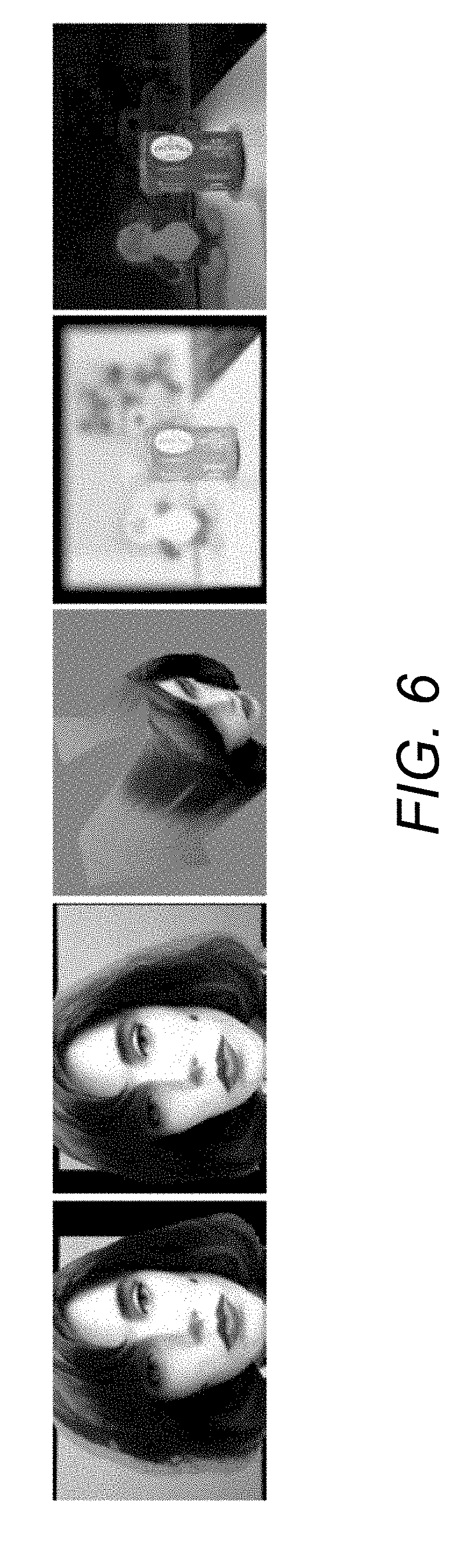
D00013
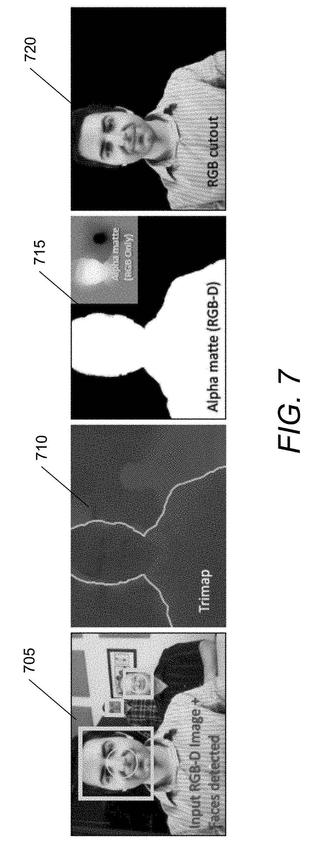
D00014
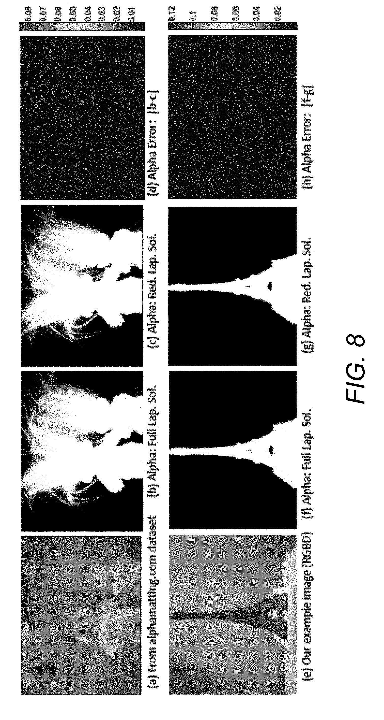
D00015
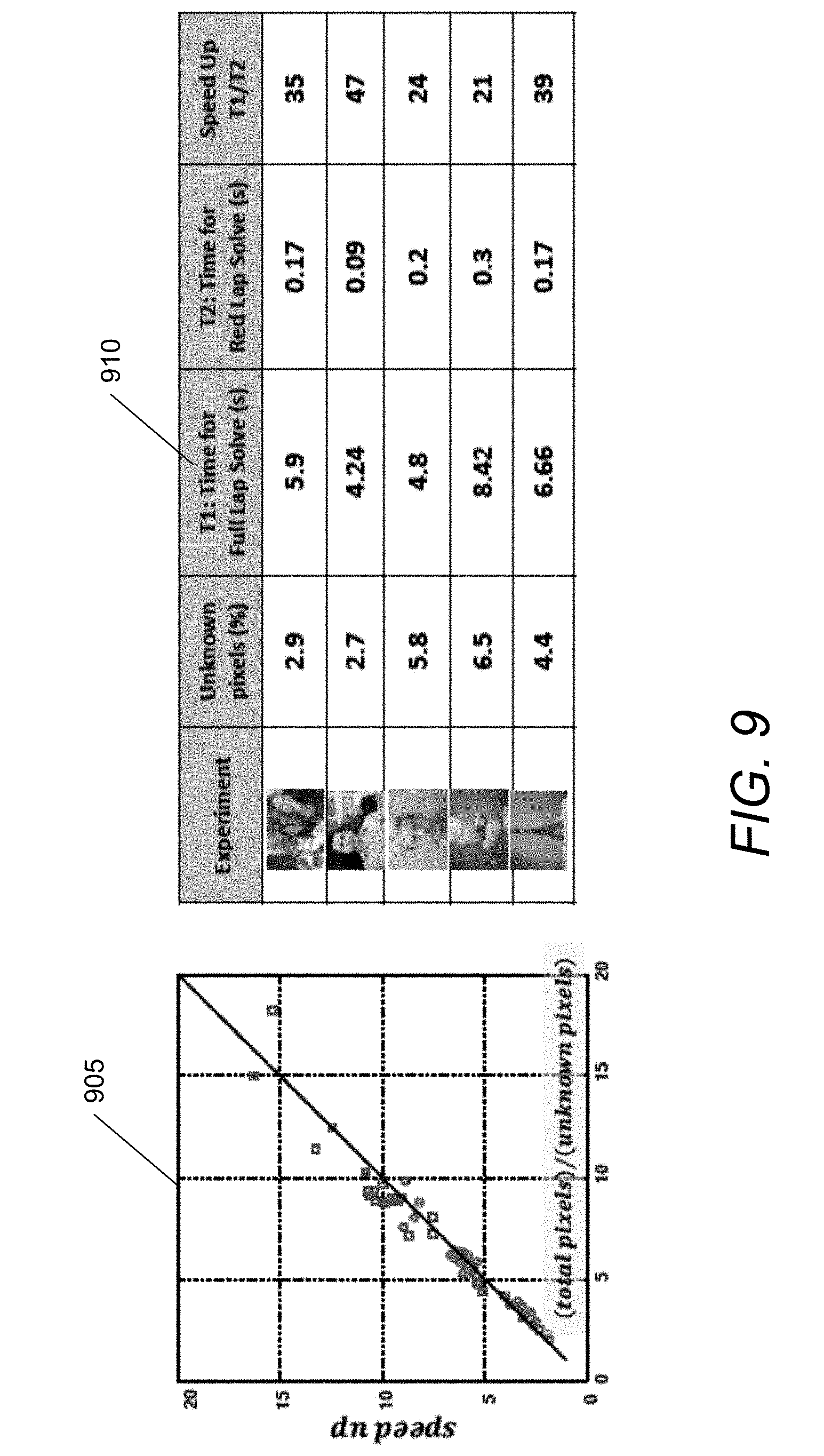
D00016
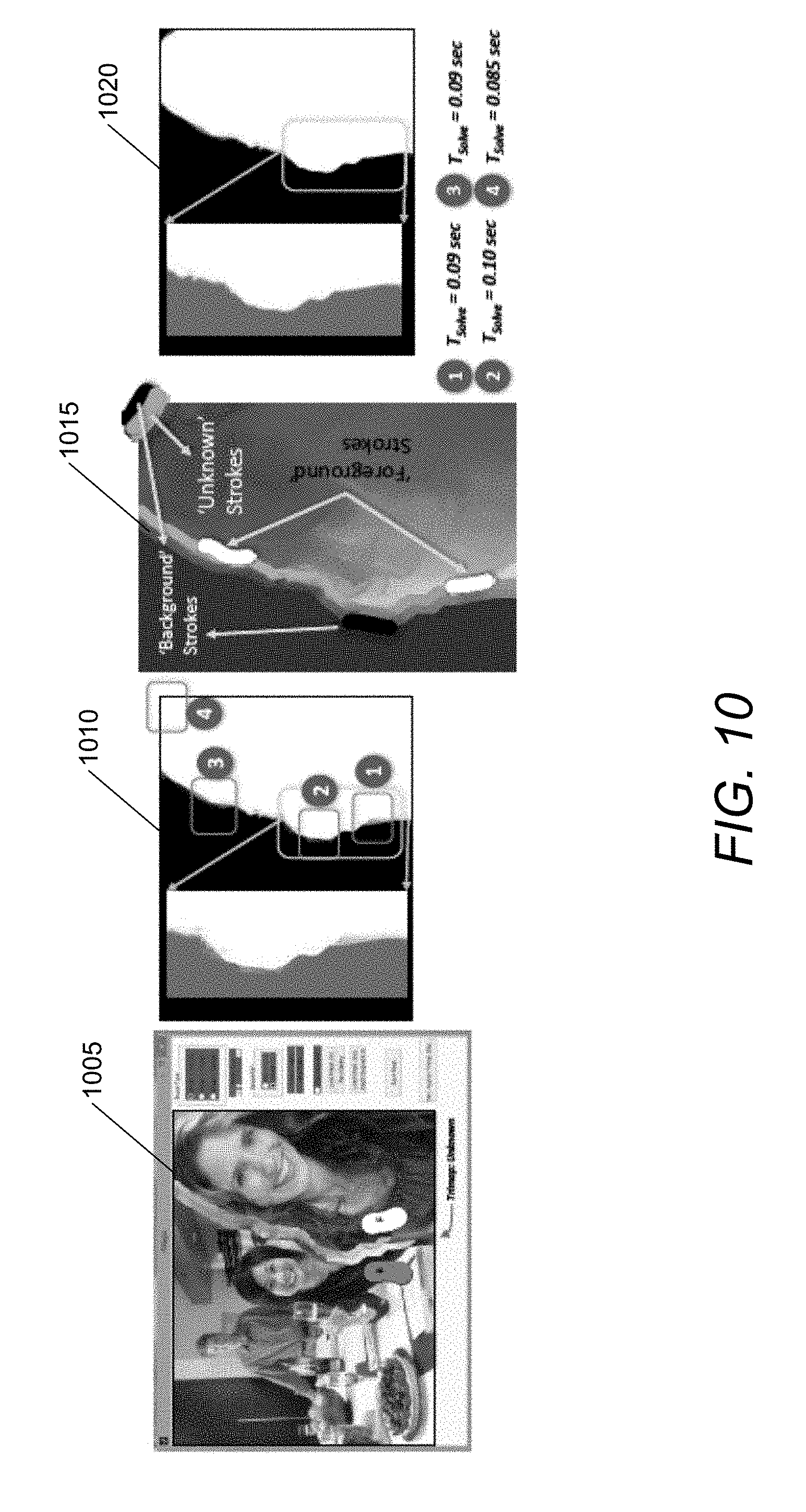
D00017
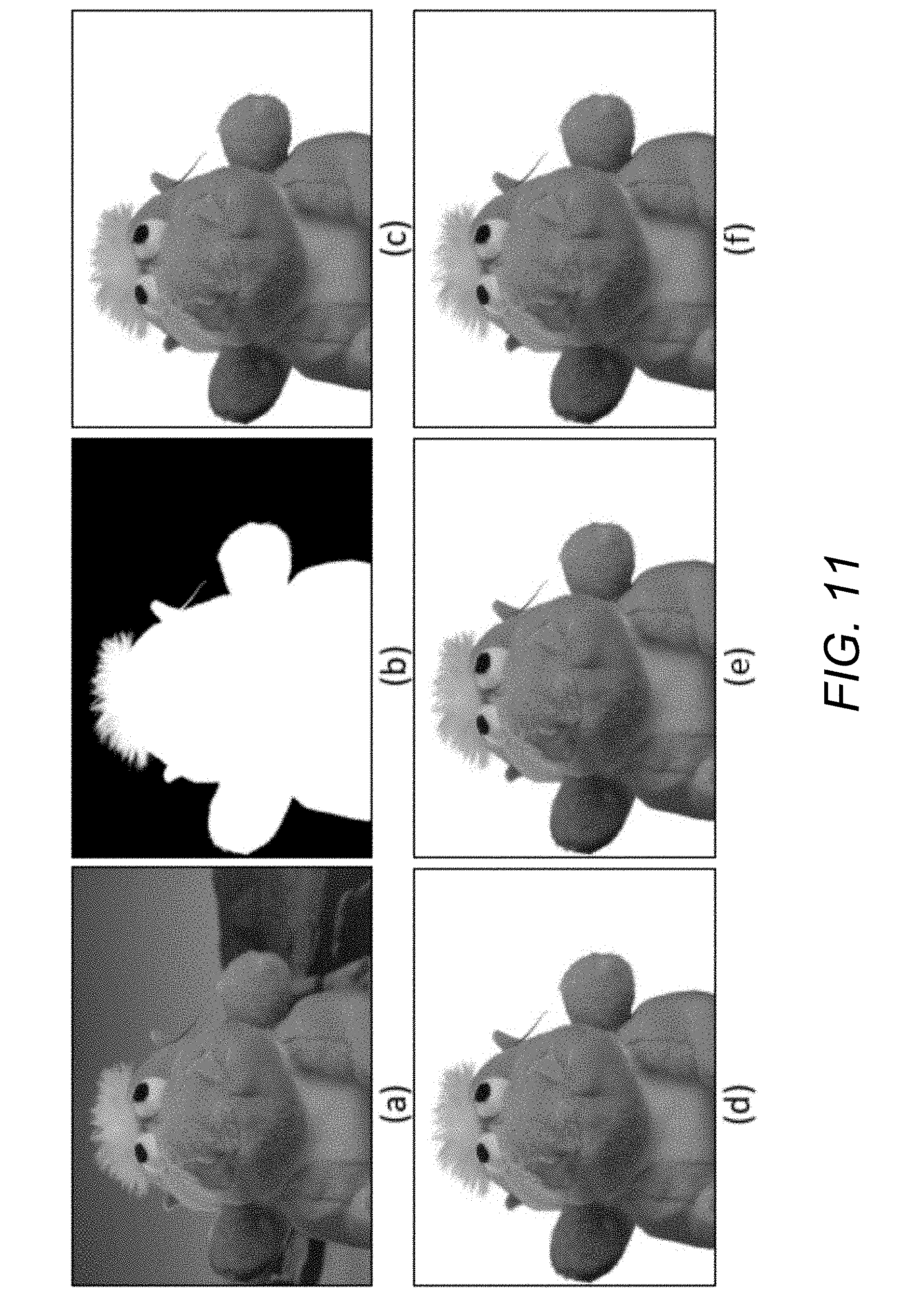
D00018
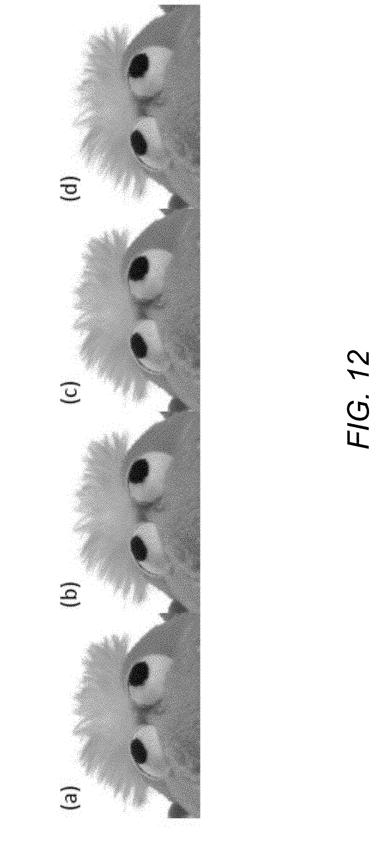
D00019
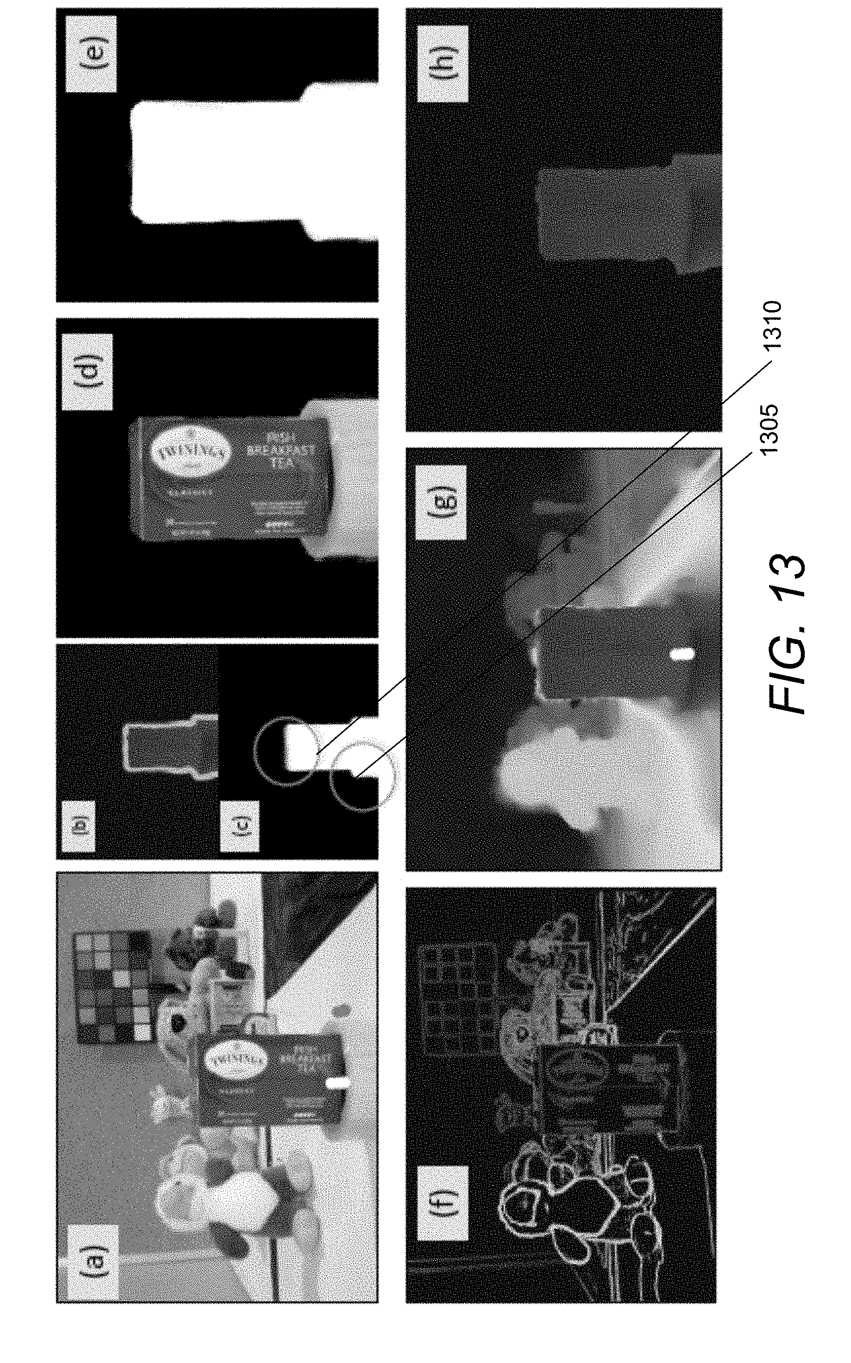
D00020
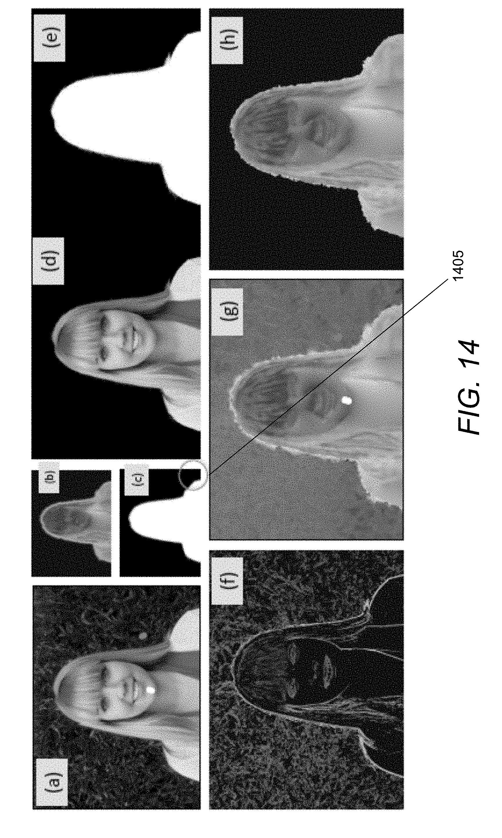
D00021
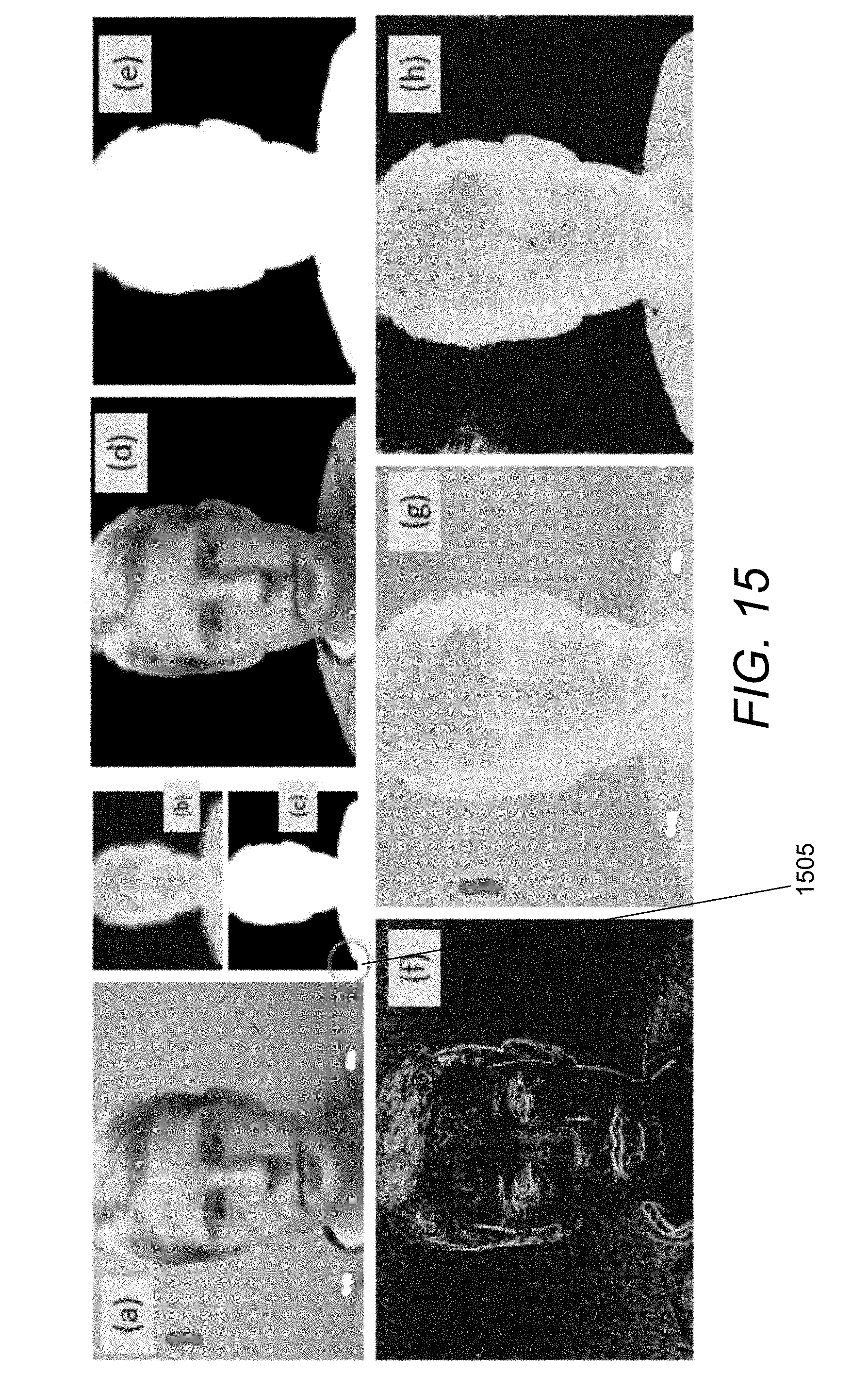
D00022
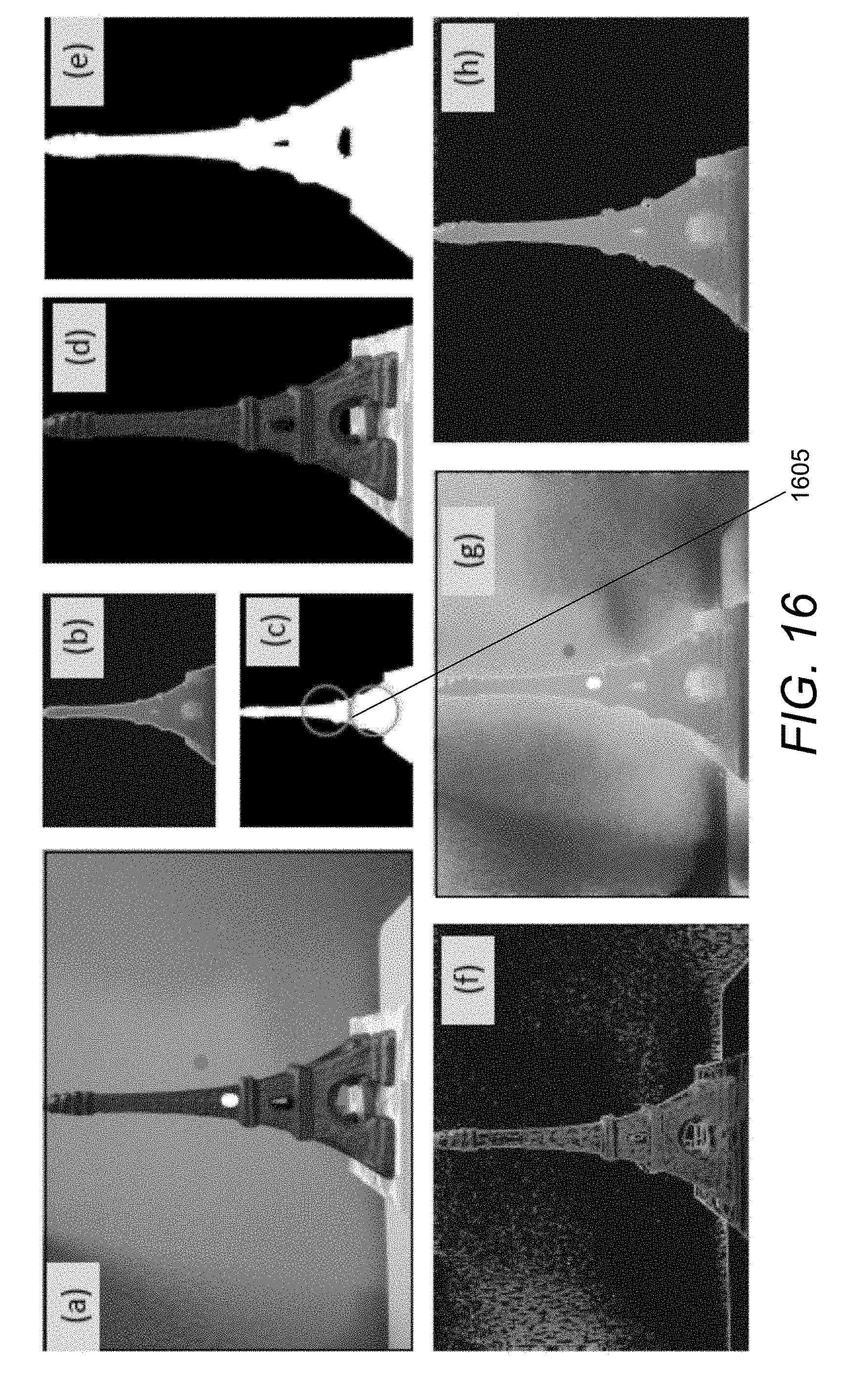
D00023
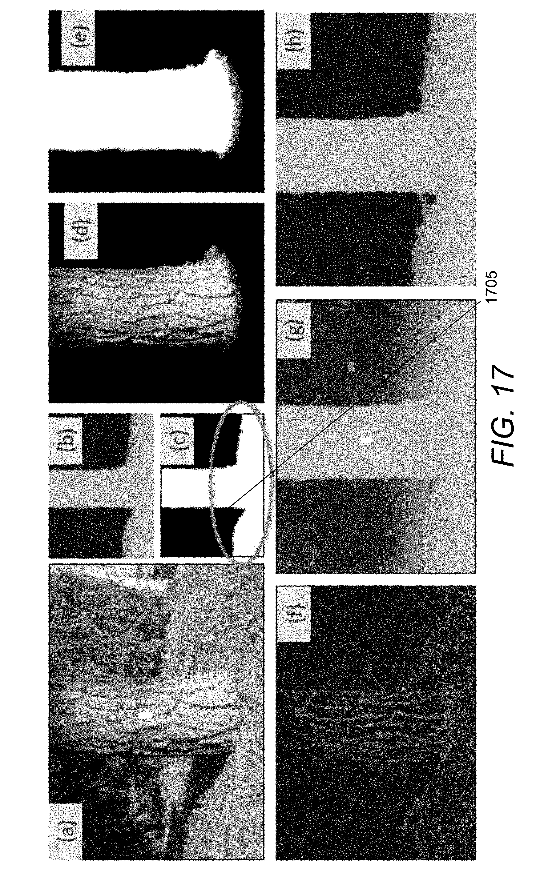
D00024
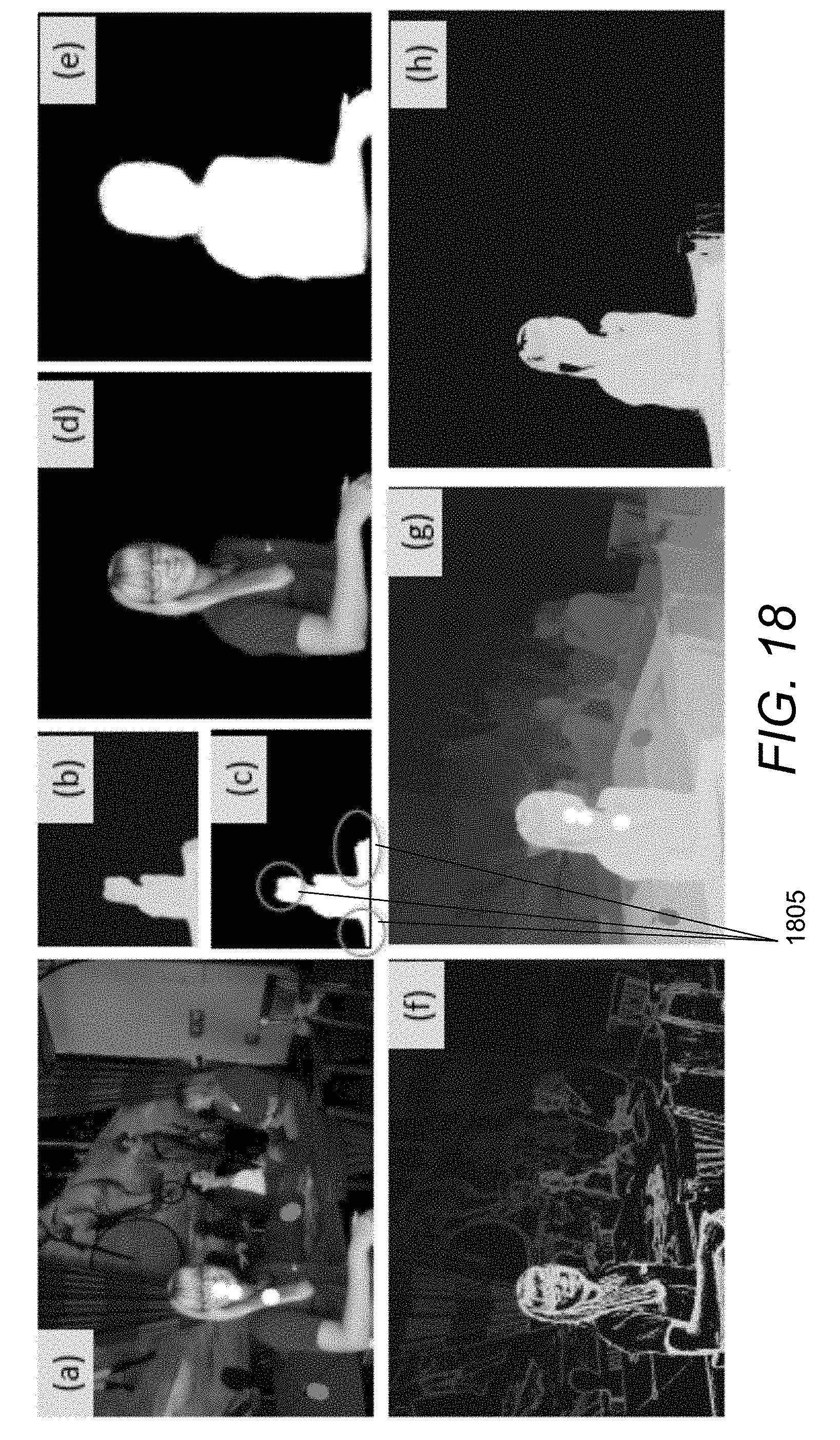
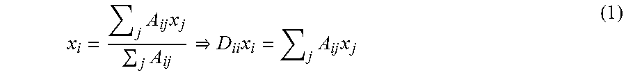

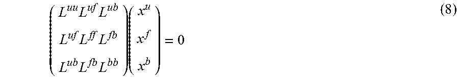
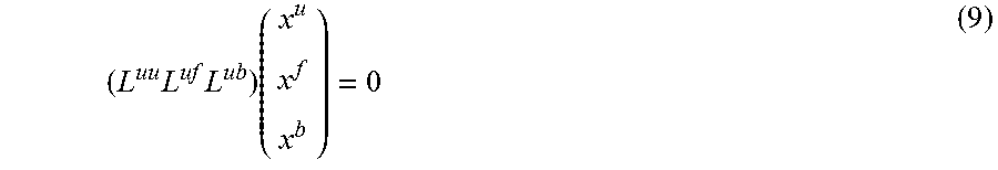
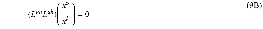


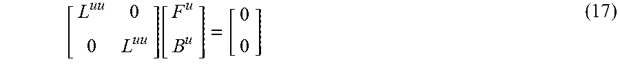

P00001

P00002

XML
uspto.report is an independent third-party trademark research tool that is not affiliated, endorsed, or sponsored by the United States Patent and Trademark Office (USPTO) or any other governmental organization. The information provided by uspto.report is based on publicly available data at the time of writing and is intended for informational purposes only.
While we strive to provide accurate and up-to-date information, we do not guarantee the accuracy, completeness, reliability, or suitability of the information displayed on this site. The use of this site is at your own risk. Any reliance you place on such information is therefore strictly at your own risk.
All official trademark data, including owner information, should be verified by visiting the official USPTO website at www.uspto.gov. This site is not intended to replace professional legal advice and should not be used as a substitute for consulting with a legal professional who is knowledgeable about trademark law.