Systems And Methods For Reducing Motion Blur In Images Or Video In Ultra Low Light With Array Cameras
MOLINA; Gabriel
U.S. patent application number 16/148317 was filed with the patent office on 2019-01-31 for systems and methods for reducing motion blur in images or video in ultra low light with array cameras. The applicant listed for this patent is FotoNation Limited. Invention is credited to Gabriel MOLINA.
| Application Number | 20190037116 16/148317 |
| Document ID | / |
| Family ID | 51625251 |
| Filed Date | 2019-01-31 |


| United States Patent Application | 20190037116 |
| Kind Code | A1 |
| MOLINA; Gabriel | January 31, 2019 |
SYSTEMS AND METHODS FOR REDUCING MOTION BLUR IN IMAGES OR VIDEO IN ULTRA LOW LIGHT WITH ARRAY CAMERAS
Abstract
Systems and methods for reducing motion blur in images or video in ultra low light with array cameras in accordance with embodiments of the invention are disclosed. In one embodiment, a method for synthesizing an image from multiple images captured using an array camera includes capturing image data using active cameras within an array camera, where the active cameras are configured to capture image data and the image data includes pixel brightness values that form alternate view images captured from different viewpoints, determining sets of corresponding pixels in the alternate view images where each pixel in a set of corresponding pixels is chosen from a different alternate view image, summing the pixel brightness values for corresponding pixels to create pixel brightness sums for pixel locations in an output image, and synthesizing an output image from the viewpoint of the output image using the pixel brightness sums.
| Inventors: | MOLINA; Gabriel; (Sunnyvale, CA) | ||||||||||
| Applicant: |
|
||||||||||
|---|---|---|---|---|---|---|---|---|---|---|---|
| Family ID: | 51625251 | ||||||||||
| Appl. No.: | 16/148317 | ||||||||||
| Filed: | October 1, 2018 |
Related U.S. Patent Documents
| Application Number | Filing Date | Patent Number | ||
|---|---|---|---|---|
| 15438542 | Feb 21, 2017 | 10091405 | ||
| 16148317 | ||||
| 14776553 | Sep 14, 2015 | 9578259 | ||
| PCT/US2014/025100 | Mar 12, 2014 | |||
| 15438542 | ||||
| 61783441 | Mar 14, 2013 | |||
| Current U.S. Class: | 1/1 |
| Current CPC Class: | H04N 5/272 20130101; H04N 5/2351 20130101; H04N 5/23248 20130101; H04N 5/235 20130101; H04N 5/2258 20130101; G06T 2207/20221 20130101; G06T 7/55 20170101; G06T 5/50 20130101; G06T 3/4015 20130101; H04N 5/265 20130101; G06T 3/4038 20130101; H04N 5/23264 20130101 |
| International Class: | H04N 5/225 20060101 H04N005/225; H04N 5/232 20060101 H04N005/232; H04N 5/235 20060101 H04N005/235; G06T 3/40 20060101 G06T003/40; H04N 5/265 20060101 H04N005/265; G06T 5/50 20060101 G06T005/50; H04N 5/272 20060101 H04N005/272; G06T 7/55 20060101 G06T007/55 |
Claims
1. A method for synthesizing an image from multiple images captured from different viewpoints using an array camera in low light conditions, the method comprising: capturing image data using a plurality of active cameras within an array camera, where the plurality of active cameras are configured to capture image data within the same spectral band and the image data captured by the active cameras comprises pixel brightness values that form a reference image and a plurality of alternate view images captured from different viewpoints; applying geometric shifts to shift the plurality of alternate view images to the viewpoint of the reference image using the processor configured by software; summing the pixel brightness values for pixels in the reference image with pixel brightness values for corresponding pixels in the alternate view images to create pixel brightness sums for the pixel locations in the reference image using the processor configured by software; and synthesizing an output image from the viewpoint of the reference image using image data comprising the pixel brightness sums for the pixel locations in the reference image using the processor configured by software.
Description
CROSS-REFERENCE TO RELATED APPLICATIONS
[0001] The current application is a continuation of U.S. patent application Ser. No. 15/438,542 entitled "Systems and Methods for Reducing Motion Blur in Images or Video in Ultra Low Light with Array Cameras" to Gabriel Molina filed Feb. 21, 2017 which application is a continuation of U.S. patent application Ser. No. 14/776,553, entitled "Systems and Methods for Reducing Motion Blur in Images or Video in Ultra Low Light with Array Cameras" to Gabriel Molina, filed Sep. 14, 2015 and issued as U.S. Pat. No. 9,578,259 on Feb. 21, 2017, which application is a 35 U.S.C. .sctn. 371 National Stage patent application of PCT Patent Application Serial No. PCT/US2014/025100 entitled "Systems and Methods for Reducing Motion Blur in Images or Video in Ultra Low Light With Array Cameras" to Gabriel Molina, filed Mar. 12, 2014, which application claims priority under 35 U.S.C. .sctn. 119(e) to U.S. Provisional Application Ser. No. 61/783,441, entitled "Systems and Methods for Reducing Motion Blur in Images or Video in Ultra Low Light with Array Cameras" to Gabriel Molina filed Mar. 13, 2013, the disclosures of which are hereby incorporated by reference in their entirety.
FIELD OF THE INVENTION
[0002] The present invention relates generally to capturing digital images and video and more specifically to the use of array cameras to reduce motion blur and/or noise when capturing images and video in low light conditions.
BACKGROUND OF THE INVENTION
[0003] Low light image capture traditionally presents challenges in producing images without excessive blurring or noise. Settings on a digital camera can typically be adjusted to compensate for low light conditions. In a digital camera, individual image sensors corresponding to pixels in an output image receive light over a predetermined exposure time (also called integration time). The exposure setting of an image sensor is typically the duration of time which light is sampled by individual pixel(s) in the image sensor. An analog gain is typically implemented through a circuit that amplifies the analog signal from a sensor before it is converted to a digital signal and processed. The exposure and gain settings on image sensors in the camera are particularly relevant in low light conditions, as increases in exposure and gain generally increase the voltage level of a pixel and thereby its apparent brightness. Under low light conditions the use of a longer exposure time can provide a brighter image but may result in motion blur, where moving objects in the scene are blurred because of movement over the time that light associated with those objects is being received by the camera. Increasing the gain can also provide a brighter image but can result in amplified noise artifacts.
SUMMARY OF THE INVENTION
[0004] Systems and methods for reducing motion blur in images or video in ultra low light with array cameras in accordance with embodiments of the invention are disclosed. In one embodiment, a method for synthesizing an image from multiple images captured from different viewpoints using an array camera includes capturing image data using active cameras within an array camera, where the active cameras are configured to capture image data and the image data captured by the active cameras includes pixel brightness values that form alternate view images captured from different viewpoints, determining sets of corresponding pixels in the alternate view images where each pixel in a set of corresponding pixels is chosen from a different alternate view image, summing the pixel brightness values for corresponding pixels in the alternate view images to create pixel brightness sums for pixel locations in an output image, and synthesizing an output image from the viewpoint of the output image using the pixel brightness sums for the pixel locations in the output image.
BRIEF DESCRIPTION OF THE DRAWINGS
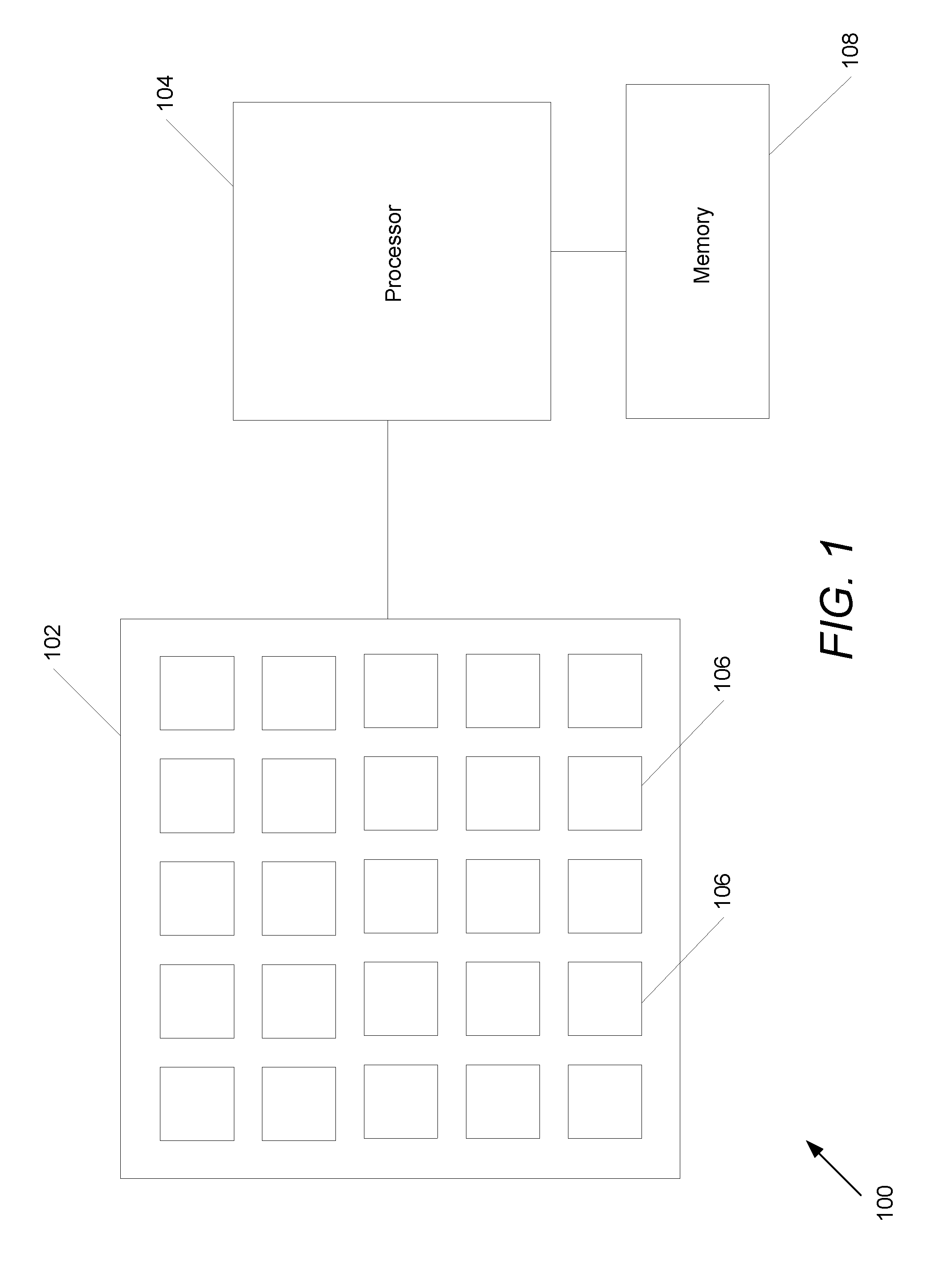
[0005] FIG. 1 is a conceptual illustration of an array camera architecture that can be used in a variety of array camera configurations in accordance with embodiments of the invention.
[0006] FIG. 1A conceptually illustrates an optic array and an imager array in an array camera module in accordance with an embodiment of the invention.
[0007] FIG. 2 is a conceptual illustration of a .pi. filter arrangement that can be used in a variety of array camera configurations in accordance with embodiments of the invention.
[0008] FIG. 3 is a flow chart showing a process for summing pixel brightness values from multiple images obtained using an array camera in accordance with an embodiment of the invention.
[0009] FIG. 4 is a flow chart showing a process for summed pixel brightness values from image data captured from a reference viewpoint and one or more alternate viewpoints in accordance with embodiments of the invention.
DETAILED DISCLOSURE OF THE INVENTION
[0010] Turning now to the drawings, systems and methods for reducing motion blur in images or video in ultra low light with array cameras in accordance with embodiments of the invention are illustrated. Array cameras including camera modules that can be utilized to capture image data from different viewpoints are disclosed in U.S. patent application Ser. No. 12/935,504, entitled "Capturing and Processing of Images using Monolithic Camera Array with Heteregeneous Images", filed May 20, 2009, the disclosure of which is incorporated by reference herein in its entirety. Array cameras offer a number of advantages and features over legacy cameras. An array camera typically contains two or more imagers (which can be referred to as cameras), each of which receives light through a separate lens system. The imagers operate to capture image data of a scene from slightly different viewpoints. Array cameras have a variety of applications, including capturing image data from multiple viewpoints that can be used in super-resolution processing and depth calculation. Imagers in the array may sense different wavelengths of light (e.g., red, green, blue, Infrared) with the application of selective filters, which can improve performance under different lighting conditions and the performance of image processing processes performed on image data captured using the array.
[0011] Array cameras in accordance with many embodiments of the invention improve the quality of images captured in low light conditions by summing the brightness of corresponding pixels from different cameras. Low light image capture is particularly challenging because the exposure time needed for a camera to receive a sufficient amount of light to produce an image can result in motion blur. Alternatively, if gain is increased to raise brightness levels, the noise level may be increased commensurately. In various embodiments of the invention, image data from a subset of cameras (imagers) in an array camera are chosen and pixel brightness values of corresponding pixels in the image data are summed, producing higher brightness levels. By summing pixel brightness values from a pixel in a reference image with a corresponding pixel from one or more alternate view image(s), the effective exposure time of the pixel in the reference image is increased by a factor equal to the number of summed pixels. Increasing exposure time can enable a reduction in analog gain and the associated noise. By exposing multiple pixels in parallel, the capture time can be significantly shorter than the effective exposure time of the pixel brightness values obtained in the reference viewpoint by summing corresponding pixels. The opportunity for motion artifacts to be present in captured image data increases with increased exposure time. Therefore, enabling an effective exposure time that is significantly longer than the actual exposure time of the pixels in the reference camera will decrease the likelihood that motion artifacts will appear in the captured image data. In addition, providing an increased effective exposure time relative to the actual capture time can provide improved low light video capture performance, where exposure time is constrained by the frame rate of the video.
[0012] In a number of embodiments, image data captured by active cameras in an array camera module is rectified (i.e. scene independent geometric shifts are applied to the image data captured by the cameras) and the rectified image data is summed. In several embodiments, parallax detection and protection processes are performed to identify scene dependent geometric corrections to apply to the image data. Systems and methods for performing parallax detection and correction are disclosed in U.S. Provisional Patent Application No. 61/691,666 entitled "Systems and Methods for Parallax Detection and Correction in Imaged Captured Using Array Cameras" to Venkataraman et al. and U.S. Pat. No. 8,619,082 entitled "Systems and Methods for Parallax Detection and Correction in Images Captured Using Array Cameras that Contain Occlusions using Subsets of Images to Perform Depth Estimation" to Ciurea et al., the disclosures of which are incorporated by reference herein in their entirety. The pixel brightness values in the image data can be summed following application of the scene dependent geometric corrections. Array cameras and methods for capturing images in low lighting conditions in accordance with embodiments of the invention are discussed further below.
Array Camera Architecture
[0013] An array camera architecture that can be used in a variety of array camera configurations in accordance with embodiments of the invention is illustrated in FIG. 1. The array camera 100 includes an imager array 102, which is connected to a processor 104. Imagers 106 in the array 102 are evenly spaced in a 5.times.5 square. In other embodiments, imagers may have different spacing or can be arranged in other orientations in the array. The processor 104 is hardware, software, firmware, or a combination thereof that controls various operating parameters of the imager array 102. The processor 104 can also function to process the images received from imager array 102 to produce a synthesized higher resolution image using super resolution processes, or transfer the images to other hardware, software, firmware or a combination thereof to process the images. The system can also include memory 108 in communication with the processor 104 for storing images. Architectures for imager arrays that can be utilized in accordance with embodiments of the invention include those disclosed in U.S. patent application Ser. No. 13/106,797, entitled "Architectures for System on Chip Array Cameras" to Pain et al., the disclosure of which is incorporated herein by reference in its entirety.
[0014] Although a specific architecture is illustrated in FIG. 1, any of a variety of architectures that enable the capture of low resolution images and application of super resolution processes to produce a synthesized high resolution image can be utilized in accordance with embodiments of the invention.
Array Camera Modules
[0015] Camera modules in accordance with many embodiments of the invention can be constructed from an imager array and an optic array. A camera module in accordance with an embodiment of the invention is illustrated in FIG. 1A. The camera module 200 includes an imager array 230 including an array of focal planes 240 along with a corresponding optic array 210 including an array of lens stacks 220. Within the array of lens stacks, each lens stack 220 creates an optical channel that forms an image of the scene on an array of light sensitive pixels within a corresponding focal plane 240. Each pairing of a lens stack 220 and focal plane 240 forms a single camera 104 within the camera module. Each pixel within a focal plane 240 of a camera 104 generates image data that can be sent from the camera 104 to the processor 108. In many embodiments, the lens stack within each optical channel is configured so that pixels of each focal plane 240 sample the same object space or region within the scene. In several embodiments, the lens stacks are configured so that the pixels that sample the same object space do so with sub-pixel offsets to provide sampling diversity that can be utilized to recover increased resolution through the use of super-resolution processes.
[0016] In several embodiments, color filters in individual cameras can be used to pattern the camera module with .pi. filter groups as further discussed in U.S. Provisional Patent Application No. 61/641,165 entitled "Camera Modules Patterned with pi Filter Groups", to Nisenzon et al. filed May 1, 2012, the disclosure of which is incorporated by reference herein in its entirety. These cameras can be used to capture data with respect to different colors, or a specific portion of the spectrum. In contrast to applying color filters to the pixels of the camera, color filters in many embodiments of the invention are included in the lens stack. For example, a green color camera can include a lens stack with a green light filter that allows green light to pass through the optical channel. In many embodiments, the pixels in each focal plane are the same and the light information captured by the pixels is differentiated by the color filters in the corresponding lens stack for each filter plane. Although a specific construction of a camera module with an optic array including color filters in the lens stacks is described above, camera modules including .pi. filter groups can be implemented in a variety of ways including (but not limited to) by applying color filters to the pixels of the focal planes of the camera module similar to the manner in which color filters are applied to the pixels of a conventional color camera. In several embodiments, at least one of the cameras in the camera module can include uniform color filters applied to the pixels in its focal plane. In many embodiments, a Bayer filter pattern is applied to the pixels of one of the cameras in a camera module. In a number of embodiments, camera modules are constructed in which color filters are utilized in both the lens stacks and on the pixels of the imager array.
[0017] In several embodiments, an array camera generates image data from multiple focal planes and uses a processor to synthesize one or more images of a scene. In certain embodiments, the image data captured by a single focal plane in the sensor array can constitute a low resolution image (the term low resolution here is used only to contrast with higher resolution images), which the processor can use in combination with other low resolution image data captured by the camera module to construct a higher resolution image through super-resolution processing.
[0018] A 4.times.4 array camera module including active cameras that capture image data used to synthesize an image from the viewpoint of a reference camera in accordance with embodiments of the invention is illustrated in FIG. 2. The 4.times.4 camera module 250 includes an arrangement of cameras with color filters such that 3.times.3 subsets of cameras are patterned using .pi. filter groups. In the illustrated embodiment, a first .pi. filter group includes a green camera at each corner, a green reference camera in the center indicated by a box 252, blue cameras above and below the reference camera, and red cameras to the left and right sides of the reference camera. In several embodiments, the locations of the red and blue cameras within the .pi. filter group are swapped and/or an alternative collection of cameras can be utilized to capture image data to synthesize images. In various embodiments, a second subset of active cameras includes a row of blue, green, and red cameras placed below the .pi. filter group and a column of blue, green, and red cameras placed to the right side of the .pi. filter group with a green camera connecting the row and the column. Although all of the cameras in the array camera module illustrated in FIG. 2 are shown as capturing image data, in many embodiments one or more of the cameras within the array camera module can be idle during image capture to conserve power as appropriate to the requirements of a specific application.
[0019] In many embodiments of the invention, one camera is designated as a reference camera capturing image data from a reference viewpoint and a number of cameras with the same color filter as the reference camera are designated alternate view cameras (that capture image data from slightly different viewpoints). In the embodiment illustrated in FIG. 2, a green camera 252 is chosen as reference camera and a plurality of other green cameras in the array including second and third green cameras 254 and 256 are chosen as alternate view cameras. The alternate view cameras can include all other green cameras or a subset of the other green cameras in the array. As will be discussed in greater detail further below, the brightness values of pixels in the alternate view cameras can be summed with the brightness values of pixels in the reference camera to increase the effective exposure time of the pixels relative to the image data capture time.
[0020] In various embodiments of the invention, an array can include multiple reference cameras with multiple subsets of alternate view cameras that can be used to synthesize images with summed pixel brightness values from different viewpoints. The diversity of image data from different viewpoints can be used in various applications such as synthesizing higher resolution images with super-resolution processes. In several embodiments of the invention, a green camera indicated by a box 258 is also a reference camera. Image data from alternate view green cameras (that can be different from the alternate view cameras associated with camera 252) are combined with image data from green camera 258 to synthesize image data representative of an image from the viewpoint of the green camera 258. The image data generated from the viewpoint of the green camera 258 can be used in combination with the image data generated from the viewpoint of the green camera 252 in applications that utilize multiple images from different viewpoints such as super-resolution processes.
[0021] Although specific array camera module configurations and partitions of cameras into subsets for synthesizing images are discussed above with respect to FIG. 2, partitions of active cameras into subsets for the purpose of capturing image data for synthesizing images can be utilized with any of a variety of camera module configurations such as, but not limited to, array camera modules including any number of cameras, array camera modules in which one or more of the cameras capture image data within multiple color channels (i.e. individual cameras in the array are possibly non-monochromatic), and/or array camera modules in which not all cameras of the camera array are active (i.e. not capturing image data or performing measurements) as appropriate to the requirements of a specific application in accordance with embodiments of the invention. Processes for utilizing array camera architectures with color filters for reducing motion blur in low light conditions is discussed below.
Reducing Motion Blur by Summing Pixel Brightness Values
[0022] As explained further above, traditional techniques to increase signal levels when capturing a digital image using image sensors include changing the exposure or gain, with some negative effects in turn. When using an array camera to capture multiple images of the same scene in the same moment an additional factor is available. By adding pixel values/signal levels together between corresponding pixels in the captured image data, a higher "boosted" signal level can be achieved with less of the negative effects of modifying the exposure and/or gain of the cameras. Furthermore, this high signal level can be achieved while lowering exposure and/or gain to decrease their negative effects.
[0023] In many embodiments of the invention, a subset of cameras in the array is chosen. Pixel values in a number of images captured by the selected cameras are combined, resulting in a pixel brightness sum corresponding to an effective exposure time equal to the number of summed pixels multiplied by the actual image data capture time. In further embodiments of the invention, because the pixel values are increased by the number of cameras from which pixel values are summed, the gain and/or exposure time of each of the cameras can be reduced accordingly.
[0024] A process for generating an image from summed pixel values from multiple images captured by an array camera in accordance with embodiments of the invention is illustrated in FIG. 3. The process 300 includes determining (310) image capture settings for active cameras in an array. Image capture settings can include (but are not limited to) exposure time, analog gain, and frame rate (when capturing video). As will be discussed further below, these settings can be adjusted based on the number of active cameras used.
[0025] Image data is captured (320) using a set of active cameras in the array. Typically, each camera produces an image from its point of view and the image data forms images made up of pixel brightness values. In array cameras, often one camera is designated a reference camera and the image data captured by that camera is referred to as being captured from a reference viewpoint. In several embodiments of the invention, the set of active cameras is chosen where the cameras have color filters such that they capture information within the same spectral band (also referred to as color channel). A spectral band can correspond to a human perceptible color (e.g., red, green, blue) or can be non-perceptible (e.g., infrared). As discussed further above, an array camera may utilize a filter pattern such that it contains cameras that separately capture green, red, and blue light (designated green, red, and blue cameras respectively). Therefore, a set of active cameras can include all cameras of one color, such as green cameras.
[0026] The pixel brightness values of corresponding pixels in the image data captured from alternate viewpoints are summed (340). Corresponding pixels can refer to pixels that represent the same scene content in each image. Parallax, due to the different fields of view of the active cameras, can affect pixel correspondence. Some pixels that capture the same portion of a scene (i.e. pixel brightness values corresponding to samples of corresponding portions of the object space) may be in different locations in different images due to parallax. In many embodiments of the invention, images are compensated (330) for parallax. Parallax compensation such as applying scene-dependent geometric shifts to the affected pixels is discussed further below. Images can also be compensated for distortions due to the physical characteristics of the particular imager (also referred to as geometric compensation or correction) using scene-independent geometric shifts to align corresponding pixels.
[0027] In many embodiments of the invention, one image is designated a reference image and the other images in the set of images are referred to as alternate view images. The designation of a reference image has particular relevance in determining a reference viewpoint and compensating for parallax. Where one image is designated a reference image, the pixels of the reference image are summed with corresponding pixels in alternate view images. In other embodiments, the reference image may be a `virtual` image synthesized in a location in the array where no physical camera exists. When a `virtual` image is used, the corresponding pixels from alternate view images can be summed into the grid for a reference viewpoint where image data may not physically exist. Systems and methods for generating a `virtual` image from the perspective of a given viewpoint include, but are not limited to, those disclosed in U.S. Provisional Application No. 61/707,691 entitled "Synthesizing Images From Light Fields Utilizing Virtual Viewpoints" to Jain, filed Sep. 28, 2012, U.S. application Ser. No. 14/042,275 entitled "Generating Images from Light Fields Utilizing Virtual Viewpoints" to Nisenzon et al., filed Sep. 30, 2013, U.S. Provisional Application No. 61/776,751 entitled "Systems and Methods for Image Data Compression" to McMahon et al., filed Mar. 11, 2013, and U.S. application Ser. No. 14/204,990 entitled "Systems and Methods for Image Data Compression" to McMahon et al., filed Mar. 11, 2014, the disclosures of which are hereby incorporated by reference in their entirety.
[0028] An output image is synthesized (350) from the pixel brightness sums. Where a reference image has been designated, values equal to the pixel brightness sums corresponding to pixels in the reference image can be placed in the same locations in the output image. Where multiple references images have been designated, super-resolution processes can be utilized to synthesize a higher resolution image using the pixel brightness sums determined for each of the reference images. In other words, multiple independently summed images can be used as inputs to a super-resolution process to generate a higher resolution image.
[0029] In further embodiments of the invention, image capture settings such as exposure time and gain can be adjusted in view of the higher signal levels resulting from the summation. For example, presume image data is captured using a 4.times.4 array where eight cameras have green filters. Image data can be combined by summing the corresponding pixels from the eight green cameras. Given that that there are eight active green cameras, the pixel brightness values are approximately eight times higher than the pixel brightness values of an image from a single green camera. Under these conditions, the exposure time can be reduced by eight times, having the effect of maintaining the same apparent brightness and noise while reducing the apparent motion blur. Alternatively, the analog gain of cameras can be reduced by eight times, having the effect of reducing the apparent noise in the image while maintaining the same brightness, or the exposure time and the analog gain can each be reduced by an amount (such as half exposure and one quarter analog gain) so that there is a total reduction by a factor of eight.
[0030] If multiple images are captured over time to generate a video sequence, the frame rate (i.e., rate at which images are captured) can be adjusted. The theoretical maximum exposure time is the inverse of frame rate. As exposure time is decreased, the frame rate can be increased accordingly. Image capture settings such as exposure time, gain, and frame rate can be determined (310) before the images are captured. Although specific processes for increasing the effective exposure times of pixels in a reference image relative to the actual image data capture time by a factor equal to the number of summed pixels are discussed above with reference to FIG. 3, any of a variety of processes can be utilized to increase effective exposure times of pixels in a reference image by summing the pixel brightness values in the reference image with the pixel brightness values of corresponding pixels in alternate view images can be utilized as appropriate to the requirements of specific applications in accordance with embodiments of the invention. The effects of parallax and techniques to compensate for parallax when summing corresponding pixels to increase effective pixel exposure times in accordance with embodiments of the invention are discussed below.
Disparity and Compensating for Parallax
[0031] Images of a scene captured by different cameras in an array camera can have slight differences due to the different fields of view resulting from the different locations of the cameras, an effect known as parallax. These differences, referred to as disparity, provide information that can be used to measure depth of objects within a scene. Once depth information has been determined, scene-dependent geometric shifts can be applied to the pixels of the captured images to remove the differences in the images that resulted from parallax. The modified images then have similar pixels, corresponding to the same observed points in the scene, in the same locations. Systems and methods for detecting and correcting parallax are discussed in U.S. Patent Application Ser. No. 61/691,666 entitled "Systems and Methods for Parallax Detection and Correction in Images Captured Using Array Cameras" to Venkataraman et al. and U.S. Pat. No. 8,619,082, the disclosures of which are incorporated by reference above.
[0032] Techniques such as those disclosed in the patent application incorporated above are typically used to generate a depth map from a reference viewpoint. The reference viewpoint can be from the viewpoint of one of the cameras in a camera array. Alternatively, the reference viewpoint can be an arbitrary virtual viewpoint. A depth map indicates the distance of the surfaces of scene objects from a reference viewpoint and can be utilized to determine scene dependent geometric corrections to apply to the pixels from each of the images within captured image data to eliminate disparity when fusing images together as in super-resolution processing (generating a higher-resolution image from multiple lower-resolution images) and/or when summing pixel brightness values for corresponding pixels.
[0033] Corrections for parallax may be desired when parallax results in scene differences in the images used for corresponding pixel summation. In several embodiments of the invention, the processes discussed above can be utilized without parallax correction where no objects are within a certain distance or where the minimum depth at which objects appear in the image (or equivalently, disparity) is determined to be below a certain threshold. For example, sparse depth information can be generated for a reference image and the pixel brightness values in the reference view image data are summed with pixel brightness values in alternate view image data when no objects are within a threshold distance according to the generated depth information. In further embodiments of the invention, images can be compensated for parallax in all situations or where the depth of objects in the image is determined to be above a predetermined threshold.
[0034] A process for generating summed pixel values from image data captured from a reference viewpoint and one or more alternate viewpoints, where parallax detection and correction is utilized to identify corresponding pixels within the image data in the in accordance with embodiments of the invention is illustrated in FIG. 4. Similar to the process described above with respect to FIG. 3, image capture settings can be determined (410) and image data captured (420). Depth measurements are calculated using at least a portion of the image data (430) and a determination is made whether any objects in the scene are within a predetermined threshold depth/distance from the camera (440). If no objects are within the predetermined threshold, pixel brightness values are summed (450) and an output image generated (460). If there is at least one object within the threshold distance, parallax correction is performed. Techniques for correcting for parallax can be utilized in a variety of ways. Processes such as those disclosed in U.S. Provisional Patent Application No. 61/780,974 entitled "Systems and Methods for Synthesizing Images from Image Data Captured by an Array Camera Using Depth Maps in which Depth Estimation Precision and Spatial Resolution Vary" to Venkataraman et al. and U.S. patent application Ser. No. 14/207,254 entitled "Systems and Methods for Synthesizing Images from Image Data Captured by an Array Camera Using Restricted Depth of Field Depth Maps in which Depth Estimation Precision Varies" to Venkataraman et al. can be utilized to correct parallax in images before pixel summing as discussed below. The disclosures of U.S. Patent Application Ser. No. 61/780,974 and Ser. No. 14/207,254 are hereby incorporated by reference in their entirety. In many embodiments of the invention, parallax detection and compensation includes one or more modes as will be discussed below.
[0035] In a first mode of operation, referred to here as user plane focus mode, parallax detection and correction is only performed with respect to pixel brightness values that sample objects in the scene that are at a specific focus depth and/or within a specific depth of field relative to the focus depth. The focus depth can be determined from at least one designated region of interest within the captured image and/or a preview image. The region of interest can be a predetermined location (e.g., an auto-focus rectangle in the center of the image) or can be selected by a user in real time. A sparse depth map can be created with higher resolution with respect to regions of the image containing objects that are located within the specified depth of field relative to the specified focus depth. Systems and methods for generating sparse depth maps include, but are not limited to, those disclosed in U.S. Patent Application Ser. No. 61/780,974 and Ser. No. 14/207,254 incorporated by reference above. In some embodiments, the depth detection might occur with denser depth sampling in the desired depth-of-field and less dense depth sampling outside the desired depth-of-field. In other embodiments, the depth of field may be set to be extremely small such that the depth detection might be entirely skipped and the depth map may be assumed to consist only of pixels at the target depth. Using the depth map, the disparity between a reference viewpoint and the alternate viewpoints can be determined (470) using the baseline between each of the alternate view cameras and the reference camera. The disparity can then be used to identify (480) corresponding pixels within the image data based upon the anticipated scene-dependent geometric shifts present in the image data. In this way, the pixels in the reference plane that are in focus are summed using corresponding pixels identified in a manner that accounts for disparity between the reference viewpoint and an alternate viewpoint. In this way, the parallax detection and correction process can reduce any blur that may be introduced by summing pixels that are incorrectly identified as corresponding. After parallax compensation, objects in the target focus depth of field will be aligned across the alternate images and summing the pixels containing those objects provides a higher effective exposure in the final image for those objects. Pixels containing objects not at the target focus depth may not be aligned across the images and summing those pixels may result in blurring. However, there may already be blurring due to the target focus not being set for those objects (they are "out of focus") so the additional blurring may not be visually significant.
[0036] In a second mode, referred to here as dense parallax compensated mode, parallax correction is performed for all pixels in an image before being summed. In this mode, a depth map is calculated for all pixels in a reference image and corresponding pixels in the alternate images are identified based upon the scene-dependent geometric shifts (470) (480) with respect to the reference image predicted by the depth map.
[0037] In a third mode, all pixels in an image are compensated before being summed. However, the same compensation is applied to all pixels irrespective of their depth indicated on a depth map. The uniform compensation can be based on a chosen depth. In many embodiments, the depth can be determined by identifying a region of interest (using techniques such as those discussed above) and calculating a depth map of the region. In several embodiments, a histogram of the depths in the region is formed. In some embodiments, the histogram can be filtered to eliminate low confidence regions of the depth map such as textureless regions or to admit only high confidence regions such as edges. In many embodiments, the median depth of the histogram is taken to be the desired depth of focus. Systems and methods for determining a depth of focus include, but are not limited to, those disclosed in U.S. Patent Application Ser. No. 61/780,974 and Ser. No. 14/207,254 incorporated by reference above. The depth is then used to compensate all pixels before summing (can be seen as equivalent to setting a depth map to a fixed depth everywhere). This will tend to attenuate regions of the image that are off the desired focal depth (not aligned) and amplify regions which are on or close to the focal depth (aligned). For objects in the reference viewpoint which are actually at or near the target depth, corresponding pixels will naturally align and the summed image will have an appearance of sharpness. For objects in the reference viewpoint which are not actually at or near the target depth, the resulting summed pixel will be an average of many non-corresponding pixels. The resulting image will typically be a synthetic aperture image where objects at the target depth will appear sharper and brighter than objects far from the target depth, which will appear blurred. This mode can allow reduced computation in situations where parallax processing is too computationally demanding, or in applications where the scene content is typically at a fixed depth (such as usually beyond a certain distance). In many embodiments, once the final image is summed it is divided or multiplied by a scale factor as needed to set a desired target brightness for final output.
[0038] When image data is captured from different perspectives and the scene includes foreground objects, the disparity in the location of the foreground object in each of the images results in portions of the scene behind the foreground object being visible in some but not all of the images. A pixel that captures image data concerning a portion of a scene, which is not visible in images captured of the scene from other viewpoints, can be referred to as an occluded pixel. These occlusions can be detected by determining whether there is a great difference between pixels that should correspond according to depth map and disparity calculations. In many embodiments, at least some portions of images that have these occlusions are not included in the summation to avoid creating artifacts. Systems and methods for detecting occlusions and correcting for parallax include, but are not limited to, those described in U.S. Patent Application Ser. No. 61/691,666 and U.S. Pat. No. 8,619,082 incorporated by reference above.
[0039] In several embodiments, where occluded pixels are detected, only those pixels corresponding to pixels visible in the reference image can be used in the summation. In many embodiments, the occluded pixels can be left out of the summation. If pixels are left out of the summation, the total of the pixels that are summed should be scaled by a factor to match the brightness of the other summed pixels. The factor can be determined by dividing the total number of images that could potentially include the pixel by the number of cameras that actually observe that pixel. For example assume N.sub.g cameras are summed for areas of an image where all pixels are visible and N.sub.gv cameras have visibility of certain pixels in an occluded area. Those pixels with visibility are summed and the sum is multiplied by a factor of N.sub.g/N.sub.gv to compensate for the pixels left out.
[0040] Although specific techniques for parallax compensation are discussed above with respect to processes for summing pixel brightness values, any of a variety of processes can be utilized to correct parallax in accordance with embodiments of the invention. Temporal frame compensation in accordance with embodiments of the invention is discussed below.
Motion-Compensated Temporal Filtering
[0041] Noise and signal performance of array cameras in low light conditions can be further improved by temporal frame compensation. Multiple frames are captured of a scene over time (e.g., frames captured at times N-1, N, and N+1). For each pixel a motion compensation vector is determined between each frame. The motion compensation vector can be calculated between individual camera images captured for each frame or between summed images formed from the images corresponding to each frame (that is, summed image at N-1, summed image at N, and image at N+1). Using the motion compensation vectors, the brightness values of corresponding pixels between frames are added to generate an image representing the sum of images from multiple cameras and multiple frames. This summation can be divided to produce an average (which may tend to reduce noise) or can be compensated for by reducing exposure time (which may tend to reduce motion blur). Producing a color image from image data captured within discrete narrow spectral bands in accordance with embodiments of the invention is discussed below.
Combining Image Data Captured in Narrow Spectral Bands into a Color Image
[0042] When utilized with sets of cameras that capture a single color, the techniques discussed above generally produce a monochrome image in that color. In many embodiments of the invention, a composite color RGB image can be formed from monochrome images of different colors (i.e., separate color channels). As discussed above, a monochrome image can be formed by summing pixel brightness values of images from a set of cameras with the same color filter in an array. The array can contain sets of green cameras, red cameras, and blue cameras. Recognizing that the number of cameras in each set may not be equal, the summed pixel brightness values can be normalized across the sets of cameras and the summed images can be combined into a color image.
[0043] Assuming the set of green cameras has the largest number of cameras, the images from the sets of red and blue cameras can be normalized as follows. A green image is generated using the processes described above to sum pixel brightness values from green cameras. Similarly, a red image is generated from the red cameras and a blue image is generated from the blue cameras. The pixel brightness values of the red image are increased by a factor N.sub.g/N.sub.r where N.sub.g is the number of green cameras and N.sub.r is the number of red cameras. Similarly, the pixel brightness values of the blue image are increased by a factor N.sub.g/N.sub.b where N.sub.b is the number of blue cameras. The images can then be combined into a color image where the relative color levels are correct with respect to each other. Increasing the signal levels for normalization can be accomplished in a variety of ways including increasing the analog gain of cameras or multiplying the signal in the digital domain after analog-to-digital conversion.
[0044] Although the present invention has been described in certain specific aspects, many additional modifications and variations would be apparent to those skilled in the art. It is therefore to be understood that the present invention may be practiced otherwise than specifically described, including various changes in the implementation such as utilizing encoders and decoders that support features beyond those specified within a particular standard with which they comply, without departing from the scope and spirit of the present invention. Thus, embodiments of the present invention should be considered in all respects as illustrative and not restrictive.
* * * * *
D00000
D00001
D00002
D00003
D00004
D00005
XML
uspto.report is an independent third-party trademark research tool that is not affiliated, endorsed, or sponsored by the United States Patent and Trademark Office (USPTO) or any other governmental organization. The information provided by uspto.report is based on publicly available data at the time of writing and is intended for informational purposes only.
While we strive to provide accurate and up-to-date information, we do not guarantee the accuracy, completeness, reliability, or suitability of the information displayed on this site. The use of this site is at your own risk. Any reliance you place on such information is therefore strictly at your own risk.
All official trademark data, including owner information, should be verified by visiting the official USPTO website at www.uspto.gov. This site is not intended to replace professional legal advice and should not be used as a substitute for consulting with a legal professional who is knowledgeable about trademark law.