Biopsy apparatus having integrated thumbwheel mechanism for manual rotation of biopsy cannula
Chudzik , et al.
U.S. patent number 10,575,833 [Application Number 15/593,739] was granted by the patent office on 2020-03-03 for biopsy apparatus having integrated thumbwheel mechanism for manual rotation of biopsy cannula. This patent grant is currently assigned to C. R. Bard, Inc.. The grantee listed for this patent is C. R. Bard, Inc.. Invention is credited to Rafal Chudzik, Angela K. Jensen, Glen V. Lazok, Jason G. Seiger.


| United States Patent | 10,575,833 |
| Chudzik , et al. | March 3, 2020 |
Biopsy apparatus having integrated thumbwheel mechanism for manual rotation of biopsy cannula
Abstract
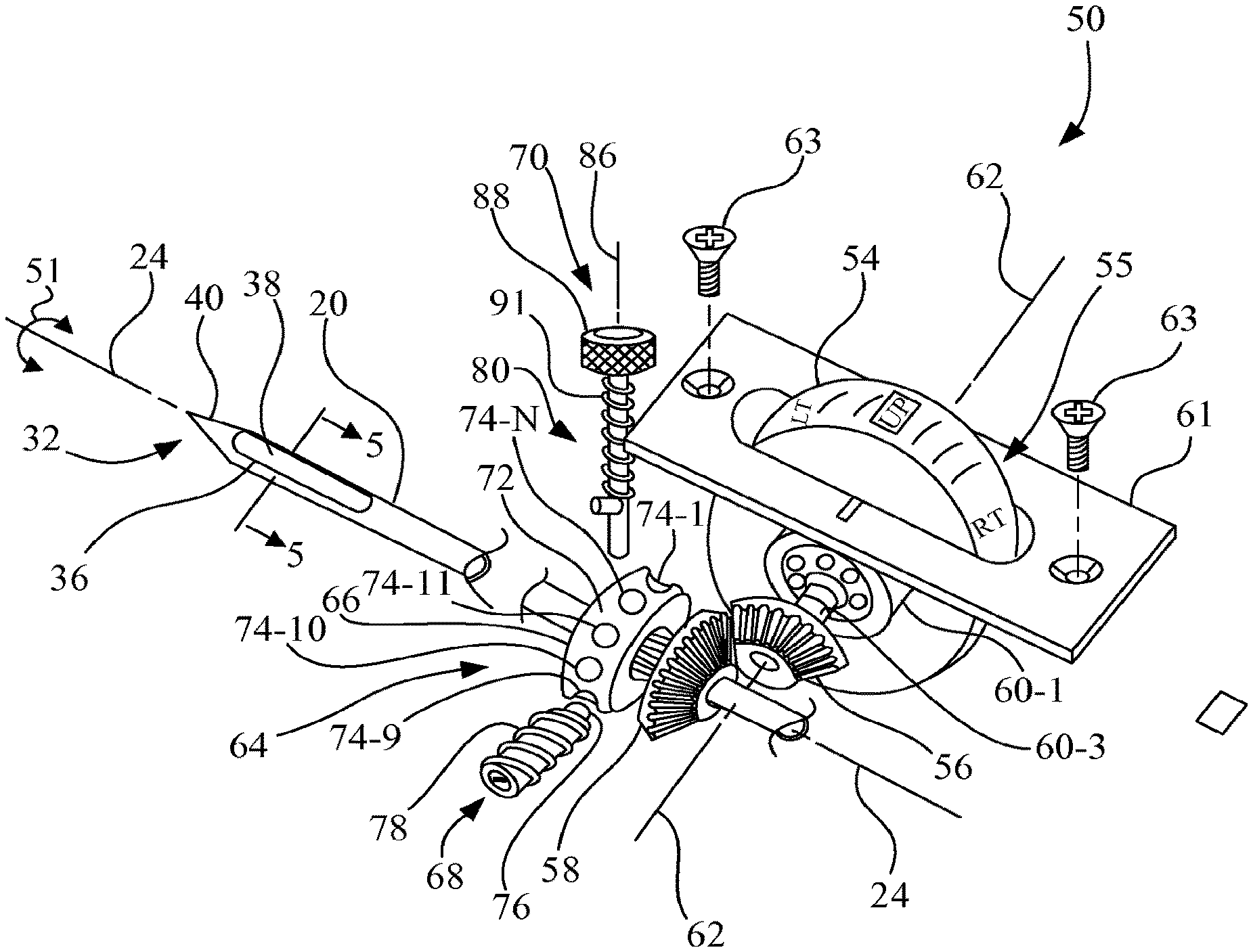
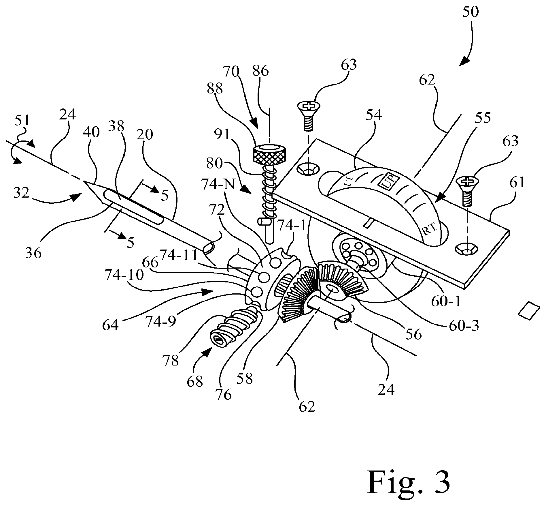
A biopsy apparatus includes a housing, a biopsy cannula mounted to the housing, and a cannula rotation mechanism mounted to the housing. The cannula rotation mechanism has a thumbwheel, a first gear, and a second gear. The thumbwheel is configured to rotate about a rotational axis, with the rotational axis being perpendicular to the longitudinal axis of the biopsy cannula. The first gear is mounted in fixed attachment to the thumbwheel. The second gear is mounted in fixed attachment to the biopsy cannula. The first gear is in mesh with the second gear such that the first gear is directly drivably engaged with the second gear to rotate the biopsy cannula about the longitudinal axis when the thumbwheel is rotated.
| Inventors: | Chudzik; Rafal (Peoria, AZ), Seiger; Jason G. (Gilbert, AZ), Jensen; Angela K. (Mesa, AZ), Lazok; Glen V. (Mesa, AZ) | ||||||||||
|---|---|---|---|---|---|---|---|---|---|---|---|
| Applicant: |
|
||||||||||
| Assignee: | C. R. Bard, Inc. (Franklin
Lakes, NJ) |
||||||||||
| Family ID: | 43586332 | ||||||||||
| Appl. No.: | 15/593,739 | ||||||||||
| Filed: | May 12, 2017 |
Prior Publication Data
| Document Identifier | Publication Date | |
|---|---|---|
| US 20170245840 A1 | Aug 31, 2017 | |
Related U.S. Patent Documents
| Application Number | Filing Date | Patent Number | Issue Date | ||
|---|---|---|---|---|---|
| 14878584 | Oct 8, 2015 | 9655599 | |||
| 13388370 | Nov 3, 2015 | 9173641 | |||
| PCT/US2009/053528 | Aug 12, 2009 | ||||
| Current U.S. Class: | 1/1 |
| Current CPC Class: | A61B 10/0283 (20130101); A61B 10/0275 (20130101); A61B 2010/0208 (20130101) |
| Current International Class: | A61B 10/02 (20060101) |
References Cited [Referenced By]
U.S. Patent Documents
| 737293 | August 1903 | Summerfeldt |
| 1585934 | May 1926 | Muir |
| 1663761 | March 1928 | Johnson |
| 2953934 | September 1960 | Sundt |
| 3019733 | February 1962 | Braid |
| 3224434 | December 1965 | Molomut et al. |
| 3289669 | December 1966 | Dwyer et al. |
| 3477423 | November 1969 | Griffith |
| 3512519 | May 1970 | Hall |
| 3561429 | February 1971 | Jewett et al. |
| 3565074 | February 1971 | Foti |
| 3606878 | September 1971 | Kellogg |
| 3727602 | April 1973 | Hyden et al. |
| 3732858 | May 1973 | Banko |
| 3785380 | January 1974 | Brumfield |
| 3800783 | April 1974 | Jamshidi |
| 3844272 | October 1974 | Banko |
| 3882849 | May 1975 | Jamshidi |
| 3889682 | June 1975 | Denis et al. |
| 3916948 | November 1975 | Benjamin |
| 4275730 | June 1981 | Hussein |
| 4282884 | August 1981 | Boebel |
| 4306570 | December 1981 | Matthews |
| 4354092 | October 1982 | Manabe et al. |
| 4393879 | July 1983 | Milgrom |
| 4445509 | May 1984 | Auth |
| 4490137 | December 1984 | Moukheibir |
| 4549554 | October 1985 | Markham |
| 4577629 | March 1986 | Martinez |
| 4589414 | May 1986 | Yoshida et al. |
| 4603694 | August 1986 | Wheeler |
| 4605011 | August 1986 | Naslund |
| 4616215 | October 1986 | Maddalena |
| 4617430 | October 1986 | Bryant |
| 4620539 | November 1986 | Andrews et al. |
| 4643197 | February 1987 | Greene et al. |
| 4645153 | February 1987 | Granzow et al. |
| 4678459 | July 1987 | Onik et al. |
| 4696298 | September 1987 | Higgins et al. |
| 4702260 | October 1987 | Wang |
| 4706687 | November 1987 | Rogers |
| 4735215 | April 1988 | Goto et al. |
| 4776346 | October 1988 | Beraha et al. |
| 4792327 | December 1988 | Swartz |
| 4832044 | May 1989 | Garg |
| 4844064 | July 1989 | Thimsen et al. |
| 4844087 | July 1989 | Garg |
| 4850354 | July 1989 | McGurk-Burleson et al. |
| 4893635 | January 1990 | de Groot et al. |
| 4907598 | March 1990 | Bauer |
| RE33258 | July 1990 | Onik et al. |
| 4940061 | July 1990 | Terwilliger et al. |
| 4952817 | August 1990 | Bolan et al. |
| 4958625 | September 1990 | Bates et al. |
| 4967762 | November 1990 | DeVries |
| 4986278 | January 1991 | Ravid et al. |
| 4986279 | January 1991 | O'Neill |
| 4986807 | January 1991 | Farr |
| 4989614 | February 1991 | Dejter, Jr. et al. |
| 5025797 | June 1991 | Baran |
| 5048538 | September 1991 | Terwilliger et al. |
| 5057822 | October 1991 | Hoffman |
| 5078603 | January 1992 | Cohen |
| 5125413 | June 1992 | Baran |
| 5138245 | August 1992 | Mattinger et al. |
| 5146921 | September 1992 | Terwilliger et al. |
| 5156160 | October 1992 | Bennett |
| 5158528 | October 1992 | Walker et al. |
| 5172702 | December 1992 | Leigh et al. |
| 5176628 | January 1993 | Charles et al. |
| 5183052 | February 1993 | Terwilliger |
| 5197484 | March 1993 | Komberg et al. |
| 5211627 | May 1993 | William |
| 5223012 | June 1993 | Best et al. |
| 5225763 | July 1993 | Krohn et al. |
| 5234000 | August 1993 | Hakky et al. |
| 5236334 | August 1993 | Bennett |
| 5242404 | September 1993 | Conley et al. |
| 5249583 | October 1993 | Mallaby |
| 5254117 | October 1993 | Rigby et al. |
| 5282476 | February 1994 | Terwilliger |
| 5282477 | February 1994 | Bauer |
| 5290253 | March 1994 | Kira |
| 5305762 | April 1994 | Acorn et al. |
| 5324306 | June 1994 | Makower et al. |
| 5334183 | August 1994 | Wuchinich |
| 5335671 | August 1994 | Clement |
| 5368029 | November 1994 | Holcombe et al. |
| 5368045 | November 1994 | Clement et al. |
| 5383874 | January 1995 | Jackson et al. |
| 5397462 | March 1995 | Higashijima et al. |
| 5400798 | March 1995 | Baran |
| 5439474 | August 1995 | Li |
| 5458112 | October 1995 | Weaver |
| 5469860 | November 1995 | De Santis |
| 5471994 | December 1995 | Guirguis |
| 5479486 | December 1995 | Saji |
| 5485917 | January 1996 | Early |
| 5492130 | February 1996 | Chiou |
| 5511556 | April 1996 | DeSantis |
| 5526822 | June 1996 | Burbank et al. |
| 5535755 | July 1996 | Heske |
| 5546957 | August 1996 | Heske |
| 5554151 | September 1996 | Hinchliffe |
| 5560373 | October 1996 | De Santis |
| 5564436 | October 1996 | Hakky et al. |
| 5569284 | October 1996 | Young et al. |
| 5575293 | November 1996 | Miller et al. |
| 5591170 | January 1997 | Spievack et al. |
| 5601583 | February 1997 | Donahue et al. |
| 5601585 | February 1997 | Banik et al. |
| 5602449 | February 1997 | Krause et al. |
| 5612738 | March 1997 | Kim |
| 5617874 | April 1997 | Baran |
| 5649547 | July 1997 | Ritchart et al. |
| 5655542 | August 1997 | Weilandt |
| 5655657 | August 1997 | Roshdy |
| 5665101 | September 1997 | Becker et al. |
| 5669394 | September 1997 | Bergey et al. |
| 5699909 | December 1997 | Foster |
| 5700265 | December 1997 | Romano |
| 5709697 | January 1998 | Ratcliff et al. |
| 5720760 | February 1998 | Becker et al. |
| 5735264 | April 1998 | Siczek et al. |
| 5752923 | May 1998 | Terwilliger |
| 5755714 | May 1998 | Murphy-Chutorian |
| 5766135 | June 1998 | Terwilliger |
| 5769086 | June 1998 | Ritchart et al. |
| 5769795 | June 1998 | Terwilliger |
| 5775333 | July 1998 | Burbank et al. |
| 5779649 | July 1998 | Herbert |
| 5788651 | August 1998 | Weilandt |
| 5792167 | August 1998 | Kablik et al. |
| 5807282 | September 1998 | Fowler |
| 5817033 | October 1998 | DeSantis et al. |
| 5817034 | October 1998 | Milliman et al. |
| 5823970 | October 1998 | Terwilliger |
| 5827305 | October 1998 | Gordon |
| 5830219 | November 1998 | Bird et al. |
| D403405 | December 1998 | Terwilliger |
| 5857982 | January 1999 | Milliman et al. |
| 5871699 | February 1999 | Ruggeri |
| 5879365 | March 1999 | Whitfield et al. |
| 5908233 | June 1999 | Heskett et al. |
| 5913857 | June 1999 | Ritchart et al. |
| 5916198 | June 1999 | Dillow |
| 5916229 | June 1999 | Evans |
| 5928164 | July 1999 | Burbank et al. |
| 5944673 | August 1999 | Gregoire et al. |
| 5951490 | September 1999 | Fowler |
| 5951575 | September 1999 | Bolduc et al. |
| 5964716 | October 1999 | Gregoire et al. |
| 5971939 | October 1999 | DeSantis et al. |
| 5976164 | November 1999 | Bencini et al. |
| 5980469 | November 1999 | Burbank et al. |
| 5980545 | November 1999 | Pacala et al. |
| 6007495 | December 1999 | Matula |
| 6007497 | December 1999 | Huitema |
| 6007556 | December 1999 | Kablik et al. |
| 6017316 | January 2000 | Ritchart et al. |
| 6018227 | January 2000 | Kumar et al. |
| 6019733 | February 2000 | Farascioni |
| 6022324 | February 2000 | Skinner |
| 6022325 | February 2000 | Siczek et al. |
| 6027458 | February 2000 | Janssens |
| 6032673 | March 2000 | Savage et al. |
| 6036657 | March 2000 | Milliman et al. |
| 6050955 | April 2000 | Bryan et al. |
| 6055870 | May 2000 | Jaeger |
| 6071247 | June 2000 | Kennedy |
| 6077230 | June 2000 | Gregoire et al. |
| 6083176 | July 2000 | Terwilliger |
| 6083237 | July 2000 | Huitema et al. |
| 6086544 | July 2000 | Hibner et al. |
| 6106484 | August 2000 | Terwilliger |
| 6110129 | August 2000 | Terwilliger |
| 6120462 | September 2000 | Hibner et al. |
| 6123957 | September 2000 | Jernberg |
| 6126617 | October 2000 | Weilandt et al. |
| 6142955 | November 2000 | Farascioni et al. |
| 6152918 | November 2000 | Padilla |
| 6162187 | December 2000 | Buzzard et al. |
| 6165136 | December 2000 | Nishtala |
| 6193673 | February 2001 | Viola et al. |
| 6196978 | March 2001 | Weilandt et al. |
| 6213957 | April 2001 | Milliman et al. |
| 6220248 | April 2001 | Voegele et al. |
| 6231522 | May 2001 | Voegele et al. |
| 6241687 | June 2001 | Voegele et al. |
| 6267759 | July 2001 | Quick |
| 6273861 | August 2001 | Bates et al. |
| 6273862 | August 2001 | Privitera et al. |
| 6280398 | August 2001 | Ritchart et al. |
| 6283925 | September 2001 | Terwilliger |
| 6322523 | November 2001 | Weilandt et al. |
| 6328701 | December 2001 | Terwilliger |
| 6331166 | December 2001 | Burbank et al. |
| 6358217 | March 2002 | Bourassa |
| 6361504 | March 2002 | Shin |
| 6402701 | June 2002 | Kaplan et al. |
| 6419641 | July 2002 | Mark et al. |
| 6428486 | August 2002 | Ritchart et al. |
| 6428487 | August 2002 | Burdorff et al. |
| 6432064 | August 2002 | Hibner et al. |
| 6432065 | August 2002 | Burdorff et al. |
| 6434507 | August 2002 | Clayton et al. |
| 6436054 | August 2002 | Viola et al. |
| 6461302 | October 2002 | Thompson |
| 6471659 | October 2002 | Eggers et al. |
| 6482158 | November 2002 | Mault |
| 6485436 | November 2002 | Truckai et al. |
| 6488636 | December 2002 | Bryan et al. |
| 6494844 | December 2002 | Van Bladel et al. |
| 6527736 | March 2003 | Attinger et al. |
| 6540694 | April 2003 | Van Bladel et al. |
| 6540761 | April 2003 | Houser |
| 6544194 | April 2003 | Kortenbach et al. |
| 6551255 | April 2003 | Van Bladel et al. |
| 6554779 | April 2003 | Viola et al. |
| 6585664 | July 2003 | Burdorff et al. |
| 6585694 | July 2003 | Smith et al. |
| 6586585 | July 2003 | Bastian |
| 6592530 | July 2003 | Farhadi |
| 6626849 | September 2003 | Huitema et al. |
| 6632182 | October 2003 | Treat |
| 6638235 | October 2003 | Miller et al. |
| 6656133 | December 2003 | Voegele et al. |
| 6659105 | December 2003 | Burbank et al. |
| 6659338 | December 2003 | Dittmann et al. |
| 6683439 | January 2004 | Takano et al. |
| 6689072 | February 2004 | Kaplan et al. |
| 6695786 | February 2004 | Wang et al. |
| 6702832 | March 2004 | Ross et al. |
| 6712773 | March 2004 | Viola |
| 6712774 | March 2004 | Voegele et al. |
| 6752768 | June 2004 | Burdorff et al. |
| 6753671 | June 2004 | Harvey |
| 6755802 | June 2004 | Bell |
| 6758824 | July 2004 | Miller et al. |
| 6764495 | July 2004 | Lee et al. |
| 6832990 | December 2004 | Kortenbach et al. |
| 6849080 | February 2005 | Lee et al. |
| 6850159 | February 2005 | Mudge |
| 6860860 | March 2005 | Viola |
| 6875183 | April 2005 | Cervi |
| 6887210 | May 2005 | Quay |
| 6908440 | June 2005 | Fisher |
| D508458 | August 2005 | Solland et al. |
| 6926676 | August 2005 | Turturro et al. |
| 6984213 | January 2006 | Horner et al. |
| 7004174 | February 2006 | Eggers et al. |
| 7010332 | March 2006 | Irvin et al. |
| 7025732 | April 2006 | Thompson et al. |
| D525583 | July 2006 | Vu |
| 7108660 | September 2006 | Stephens et al. |
| 7153274 | December 2006 | Stephens et al. |
| 7156814 | January 2007 | Williamson, IV et al. |
| 7182754 | February 2007 | Brigham et al. |
| 7189206 | March 2007 | Quick et al. |
| 7189207 | March 2007 | Viola |
| 7219867 | May 2007 | Kalis et al. |
| 7226424 | June 2007 | Ritchart et al. |
| 7252641 | August 2007 | Thompson et al. |
| 7276032 | October 2007 | Hibner |
| 7328794 | February 2008 | Lubs et al. |
| 7347828 | March 2008 | Francese et al. |
| 7347829 | March 2008 | Mark et al. |
| 7374544 | May 2008 | Freeman et al. |
| 7390306 | June 2008 | Mark |
| 7397654 | July 2008 | Mori |
| 7402140 | July 2008 | Spero et al. |
| 7405536 | July 2008 | Watts |
| 7407054 | August 2008 | Seiler et al. |
| 7419472 | September 2008 | Hibner et al. |
| 7432813 | October 2008 | Postma |
| 7452367 | November 2008 | Rassman et al. |
| 7458940 | December 2008 | Miller |
| 7464040 | December 2008 | Joao |
| 7473232 | January 2009 | Teague |
| 7481775 | January 2009 | Weikel, Jr. et al. |
| 7490048 | February 2009 | Joao |
| 7491177 | February 2009 | Hibner |
| 7494473 | February 2009 | Eggers et al. |
| 7497833 | March 2009 | Miller |
| 7510534 | March 2009 | Burdorff et al. |
| 7513877 | April 2009 | Viola |
| 7517321 | April 2009 | McCullough et al. |
| 7517322 | April 2009 | Weikel, Jr. et al. |
| 7549978 | June 2009 | Carlson et al. |
| 7575557 | August 2009 | Morton et al. |
| 7648466 | January 2010 | Stephens et al. |
| 7670299 | March 2010 | Beckman et al. |
| 7717861 | May 2010 | Weikel et al. |
| 7727164 | June 2010 | Cicenas et al. |
| 7740594 | June 2010 | Hibner |
| 7740596 | June 2010 | Hibner |
| 7740597 | June 2010 | Cicenas et al. |
| 7758515 | July 2010 | Hibner |
| 7762961 | July 2010 | Heske et al. |
| 7806834 | October 2010 | Beckman et al. |
| 7828746 | November 2010 | Teague |
| 7841991 | November 2010 | Douglas et al. |
| 7846109 | December 2010 | Parihar et al. |
| 7854706 | December 2010 | Hibner |
| 7862517 | January 2011 | Tsonton et al. |
| 7862518 | January 2011 | Parihar |
| 7871384 | January 2011 | Thompson et al. |
| 7883476 | February 2011 | Miller et al. |
| 7883494 | February 2011 | Martin |
| 7906076 | March 2011 | Fischer |
| 7914462 | March 2011 | Hutchins et al. |
| 7974681 | July 2011 | Wallace et al. |
| 8002713 | August 2011 | Heske et al. |
| 8012102 | September 2011 | McCullough et al. |
| 8016772 | September 2011 | Heske et al. |
| 8016844 | September 2011 | Privitera et al. |
| 8052614 | November 2011 | Heske et al. |
| 8052615 | November 2011 | Reuber et al. |
| 8057402 | November 2011 | Hibner et al. |
| 8073008 | December 2011 | Mehta et al. |
| 8075495 | December 2011 | Andreyko et al. |
| 8083671 | December 2011 | Boulais et al. |
| 8083687 | December 2011 | Parihar |
| 8109885 | February 2012 | Heske et al. |
| 8118755 | February 2012 | Hibner et al. |
| 8152738 | April 2012 | Li et al. |
| 8162851 | April 2012 | Heske et al. |
| 8172771 | May 2012 | Miller et al. |
| 8172773 | May 2012 | Heske et al. |
| 8187204 | May 2012 | Miller et al. |
| 8190238 | May 2012 | Moll et al. |
| 8206409 | June 2012 | Privitera et al. |
| 8251916 | August 2012 | Speeg et al. |
| 8277393 | October 2012 | Miller et al. |
| 8282574 | October 2012 | Coonahan |
| 8287465 | October 2012 | Hardin et al. |
| 8313444 | November 2012 | Thompson et al. |
| 8343069 | January 2013 | Uchiyama et al. |
| 8430825 | April 2013 | Mark |
| 8430827 | April 2013 | Nicoson et al. |
| 8597205 | December 2013 | Seiger et al. |
| 8956306 | February 2015 | Hibner |
| 9421002 | August 2016 | Heske et al. |
| 2001/0007925 | July 2001 | Ritchart et al. |
| 2001/0011156 | August 2001 | Viola et al. |
| 2001/0012919 | August 2001 | Terwilliger |
| 2001/0014779 | August 2001 | Burbank et al. |
| 2001/0034530 | October 2001 | Malackowski et al. |
| 2001/0044595 | November 2001 | Reydel et al. |
| 2001/0047183 | November 2001 | Privitera et al. |
| 2002/0000403 | January 2002 | Tanaka et al. |
| 2002/0029007 | March 2002 | Bryan et al. |
| 2002/0067151 | June 2002 | Tanishita |
| 2002/0068878 | June 2002 | Jasonni et al. |
| 2002/0082518 | June 2002 | Weiss et al. |
| 2002/0107043 | August 2002 | Adamson et al. |
| 2002/0115942 | August 2002 | Stanford et al. |
| 2002/0120212 | August 2002 | Ritchart et al. |
| 2002/0143269 | October 2002 | Neuenfeldt |
| 2002/0156395 | October 2002 | Stephens et al. |
| 2003/0023188 | January 2003 | Kritzman et al. |
| 2003/0023239 | January 2003 | Burbank et al. |
| 2003/0073929 | April 2003 | Baltschun et al. |
| 2003/0093103 | May 2003 | Malackowski et al. |
| 2003/0130593 | July 2003 | Gonzalez |
| 2003/0130677 | July 2003 | Whitman et al. |
| 2003/0163142 | August 2003 | Paltieli et al. |
| 2003/0229293 | December 2003 | Hibner et al. |
| 2003/0233101 | December 2003 | Lubock et al. |
| 2004/0015079 | January 2004 | Berger et al. |
| 2004/0019297 | January 2004 | Angel |
| 2004/0030367 | February 2004 | Yamaki et al. |
| 2004/0034280 | February 2004 | Privitera et al. |
| 2004/0049128 | March 2004 | Miller et al. |
| 2004/0054299 | March 2004 | Burdorff et al. |
| 2004/0082915 | April 2004 | Kadan |
| 2004/0092980 | May 2004 | Cesarini et al. |
| 2004/0092992 | May 2004 | Adams et al. |
| 2004/0162505 | August 2004 | Kaplan et al. |
| 2004/0167428 | August 2004 | Quick et al. |
| 2004/0186393 | September 2004 | Leigh et al. |
| 2004/0210161 | October 2004 | Burdorff et al. |
| 2004/0215103 | October 2004 | Mueller, Jr. et al. |
| 2004/0220495 | November 2004 | Cahir et al. |
| 2004/0230135 | November 2004 | Merkle |
| 2004/0230188 | November 2004 | Cioanta et al. |
| 2004/0249278 | December 2004 | Krause |
| 2004/0267157 | December 2004 | Miller et al. |
| 2005/0004492 | January 2005 | Burbank et al. |
| 2005/0004559 | January 2005 | Quick et al. |
| 2005/0010131 | January 2005 | Burbank et al. |
| 2005/0020909 | January 2005 | Moctezuma de la Barrera et al. |
| 2005/0027210 | February 2005 | Miller |
| 2005/0049489 | March 2005 | Foerster et al. |
| 2005/0049521 | March 2005 | Miller et al. |
| 2005/0054947 | March 2005 | Goldenberg |
| 2005/0065453 | March 2005 | Shabaz et al. |
| 2005/0085838 | April 2005 | Thompson et al. |
| 2005/0088120 | April 2005 | Avis |
| 2005/0101879 | May 2005 | Shidham et al. |
| 2005/0113715 | May 2005 | Schwindt et al. |
| 2005/0113716 | May 2005 | Mueller, Jr. et al. |
| 2005/0124914 | June 2005 | Dicarlo et al. |
| 2005/0124915 | June 2005 | Eggers et al. |
| 2005/0165328 | July 2005 | Heske |
| 2005/0165329 | July 2005 | Taylor et al. |
| 2005/0177117 | August 2005 | Crocker et al. |
| 2005/0187489 | August 2005 | Wardle et al. |
| 2005/0193451 | September 2005 | Quistgaard et al. |
| 2005/0209530 | September 2005 | Pflueger |
| 2005/0215921 | September 2005 | Hibner et al. |
| 2005/0275378 | December 2005 | Canino et al. |
| 2005/0277829 | December 2005 | Tsonton et al. |
| 2005/0277871 | December 2005 | Selis |
| 2005/0288605 | December 2005 | Pellegrino et al. |
| 2006/0030784 | February 2006 | Miller et al. |
| 2006/0074344 | April 2006 | Hibner |
| 2006/0074345 | April 2006 | Hibner |
| 2006/0074350 | April 2006 | Cash |
| 2006/0113958 | June 2006 | Lobert et al. |
| 2006/0116603 | June 2006 | Shibazaki et al. |
| 2006/0122535 | June 2006 | Daum |
| 2006/0129063 | June 2006 | Thompson et al. |
| 2006/0149162 | July 2006 | Daw et al. |
| 2006/0178666 | August 2006 | Cosman et al. |
| 2006/0184063 | August 2006 | Miller |
| 2006/0200042 | September 2006 | Weikel, Jr. et al. |
| 2006/0241515 | October 2006 | Jones et al. |
| 2006/0258956 | November 2006 | Haberstich et al. |
| 2006/0260994 | November 2006 | Mark et al. |
| 2007/0016101 | January 2007 | Feldman et al. |
| 2007/0032741 | February 2007 | Hibner et al. |
| 2007/0032743 | February 2007 | Hibner |
| 2007/0055173 | March 2007 | DeLonzor et al. |
| 2007/0073326 | March 2007 | Miller et al. |
| 2007/0090788 | April 2007 | Hansford et al. |
| 2007/0106176 | May 2007 | Mark et al. |
| 2007/0118048 | May 2007 | Stephens et al. |
| 2007/0118049 | May 2007 | Viola |
| 2007/0123797 | May 2007 | Krause |
| 2007/0158147 | July 2007 | Heske et al. |
| 2007/0161925 | July 2007 | Quick et al. |
| 2007/0167736 | July 2007 | Dietz et al. |
| 2007/0167782 | July 2007 | Callahan et al. |
| 2007/0167828 | July 2007 | Saadat |
| 2007/0167943 | July 2007 | Janssen et al. |
| 2007/0179401 | August 2007 | Hibner |
| 2007/0208271 | September 2007 | Voegele |
| 2007/0213590 | September 2007 | Squicciarini |
| 2007/0213630 | September 2007 | Beckman et al. |
| 2007/0213632 | September 2007 | Okazaki et al. |
| 2007/0219572 | September 2007 | Deck et al. |
| 2007/0236180 | October 2007 | Rodgers |
| 2007/0239067 | October 2007 | Hibner et al. |
| 2007/0255173 | November 2007 | Hibner |
| 2007/0270710 | November 2007 | Frass et al. |
| 2007/0276288 | November 2007 | Khaw |
| 2007/0287933 | December 2007 | Phan et al. |
| 2007/0292858 | December 2007 | Chen et al. |
| 2007/0293788 | December 2007 | Entrekin et al. |
| 2007/0293830 | December 2007 | Martin |
| 2008/0004545 | January 2008 | Garrison |
| 2008/0007217 | January 2008 | Riley |
| 2008/0021487 | January 2008 | Heisler |
| 2008/0021488 | January 2008 | Berberich |
| 2008/0030170 | February 2008 | Dacquay et al. |
| 2008/0064925 | March 2008 | Gill et al. |
| 2008/0064984 | March 2008 | Pflueger |
| 2008/0079391 | April 2008 | Schroeck et al. |
| 2008/0103411 | May 2008 | Van Bladel et al. |
| 2008/0110261 | May 2008 | Randall et al. |
| 2008/0125634 | May 2008 | Ryan et al. |
| 2008/0135443 | June 2008 | Frojd et al. |
| 2008/0146962 | June 2008 | Ritchie et al. |
| 2008/0146965 | June 2008 | Privitera et al. |
| 2008/0154151 | June 2008 | Ritchart et al. |
| 2008/0161682 | July 2008 | Kendrick et al. |
| 2008/0161718 | July 2008 | Schwindt |
| 2008/0161719 | July 2008 | Miller et al. |
| 2008/0161720 | July 2008 | Nicoson et al. |
| 2008/0183099 | July 2008 | Jorgensen et al. |
| 2008/0195066 | August 2008 | Speeg et al. |
| 2008/0200833 | August 2008 | Hardin et al. |
| 2008/0200836 | August 2008 | Speeg et al. |
| 2008/0208194 | August 2008 | Bickenbach |
| 2008/0214955 | September 2008 | Speeg et al. |
| 2008/0215056 | September 2008 | Miller et al. |
| 2008/0221443 | September 2008 | Ritchie et al. |
| 2008/0221444 | September 2008 | Ritchie et al. |
| 2008/0221478 | September 2008 | Ritchie et al. |
| 2008/0221479 | September 2008 | Ritchie et al. |
| 2008/0221480 | September 2008 | Hibner et al. |
| 2008/0228104 | September 2008 | Uber et al. |
| 2008/0232604 | September 2008 | Dufresne et al. |
| 2008/0234715 | September 2008 | Pesce et al. |
| 2008/0281225 | November 2008 | Spero et al. |
| 2008/0287826 | November 2008 | Videbaek et al. |
| 2008/0306406 | December 2008 | Thompson et al. |
| 2008/0308607 | December 2008 | Timm et al. |
| 2008/0319341 | December 2008 | Taylor et al. |
| 2009/0015208 | January 2009 | White et al. |
| 2009/0030405 | January 2009 | Quick et al. |
| 2009/0048532 | February 2009 | Stephens et al. |
| 2009/0048533 | February 2009 | Miller |
| 2009/0062624 | March 2009 | Neville |
| 2009/0082695 | March 2009 | Whitehead |
| 2009/0087249 | April 2009 | Flagle et al. |
| 2009/0088666 | April 2009 | Miller et al. |
| 2009/0112118 | April 2009 | Quick, Jr. et al. |
| 2009/0125062 | May 2009 | Arnin |
| 2009/0137927 | May 2009 | Miller |
| 2009/0137929 | May 2009 | Mccullough et al. |
| 2009/0146609 | June 2009 | Santos |
| 2009/0171242 | July 2009 | Hibner |
| 2009/0171243 | July 2009 | Hibner et al. |
| 2009/0204022 | August 2009 | Schwindt |
| 2009/0227893 | September 2009 | Coonahan et al. |
| 2009/0247833 | October 2009 | Tanaka |
| 2009/0281453 | November 2009 | Tsonton et al. |
| 2010/0030020 | February 2010 | Sanders et al. |
| 2010/0030108 | February 2010 | Anderson et al. |
| 2010/0063416 | March 2010 | Cicenas et al. |
| 2010/0102777 | April 2010 | Sa |
| 2010/0106053 | April 2010 | Videbaek et al. |
| 2010/0152610 | June 2010 | Parihar et al. |
| 2010/0152611 | June 2010 | Parihar et al. |
| 2010/0160820 | June 2010 | Weikel, Jr. et al. |
| 2010/0160823 | June 2010 | Parihar et al. |
| 2010/0160824 | June 2010 | Parihar et al. |
| 2010/0185179 | July 2010 | Chan |
| 2010/0210966 | August 2010 | Videbaek |
| 2010/0222700 | September 2010 | Hibner |
| 2010/0234760 | September 2010 | Almazan |
| 2010/0292607 | November 2010 | Moore et al. |
| 2010/0312140 | December 2010 | Smith et al. |
| 2010/0317995 | December 2010 | Hibner et al. |
| 2010/0317997 | December 2010 | Hibner et al. |
| 2010/0317998 | December 2010 | Hibner et al. |
| 2010/0324449 | December 2010 | Rostaing et al. |
| 2011/0004119 | January 2011 | Hoffa et al. |
| 2011/0021946 | January 2011 | Heske et al. |
| 2011/0054350 | March 2011 | Videbaek |
| 2011/0077551 | March 2011 | Videbaek |
| 2011/0084109 | April 2011 | Ford et al. |
| 2011/0087131 | April 2011 | Videbaek |
| 2011/0105945 | May 2011 | Videbaek et al. |
| 2011/0105946 | May 2011 | Sorensen et al. |
| 2011/0152715 | June 2011 | Delap et al. |
| 2011/0160611 | June 2011 | Ritchart et al. |
| 2011/0208085 | August 2011 | Mccullough et al. |
| 2011/0224577 | September 2011 | Park |
| 2011/0295150 | December 2011 | Mccullough et al. |
| 2011/0313316 | December 2011 | Ranpura et al. |
| 2012/0065541 | March 2012 | Videbaek |
| 2012/0071787 | March 2012 | Reuber et al. |
| 2012/0095366 | April 2012 | Heske et al. |
| 2012/0130275 | May 2012 | Chudzik et al. |
| 2012/0184873 | July 2012 | Jorgensen et al. |
| 2012/0191009 | July 2012 | Hoon et al. |
| 2012/0203135 | August 2012 | Heske et al. |
| 2012/0215130 | August 2012 | Field et al. |
| 2012/0238905 | September 2012 | Heske et al. |
| 2012/0310109 | December 2012 | Almazan |
| 2012/0323120 | December 2012 | Taylor et al. |
| 2012/0323140 | December 2012 | Taylor et al. |
| 2012/0330185 | December 2012 | Coonahan et al. |
| 2013/0023789 | January 2013 | Anderson et al. |
| 2013/0023791 | January 2013 | Thompson et al. |
| 2013/0190648 | July 2013 | Videbaek |
| 2013/0197391 | August 2013 | Videbaek |
| 2013/0289441 | October 2013 | Videbaek et al. |
| 2014/0228706 | August 2014 | Mccullough et al. |
| 2014/0371585 | December 2014 | Thompson et al. |
| 2015/0018712 | January 2015 | Seiger et al. |
| 2015/0025415 | January 2015 | Videbaek et al. |
| 2015/0073301 | March 2015 | Videbaek et al. |
| 2015/0094613 | April 2015 | Jorgensen et al. |
| 2015/0133814 | May 2015 | Almazan |
| 2015/0148702 | May 2015 | Heske et al. |
| 2015/0190124 | July 2015 | Mccullough et al. |
| 2015/0223787 | August 2015 | Coonahan et al. |
| 2015/0238174 | August 2015 | Reuber et al. |
| 2016/0256138 | September 2016 | Videbaek et al. |
| 2016/0367229 | December 2016 | Jorgensen et al. |
| 2016/0367230 | December 2016 | Almazan |
| 2016/0374650 | December 2016 | Heske et al. |
| 2017/0042517 | February 2017 | Heske et al. |
| 2017/0181732 | June 2017 | Videbaek et al. |
| 2017/0258458 | September 2017 | Seiger et al. |
| 2018/0125467 | May 2018 | Reuber et al. |
| 101011268 | Aug 2007 | CN | |||
| 101032420 | Sep 2007 | CN | |||
| 3924291 | Jan 1991 | DE | |||
| 4041614 | Oct 1992 | DE | |||
| 3924291 | Jul 2000 | DE | |||
| 10034297 | Apr 2001 | DE | |||
| 10026303 | Feb 2002 | DE | |||
| 20204363 | May 2002 | DE | |||
| 20209525 | Nov 2002 | DE | |||
| 10235480 | Feb 2004 | DE | |||
| 0433717 | Jun 1991 | EP | |||
| 0890339 | Jan 1999 | EP | |||
| 0970658 | Jan 2000 | EP | |||
| 0995400 | Apr 2000 | EP | |||
| 1074271 | Feb 2001 | EP | |||
| 1520518 | Apr 2005 | EP | |||
| 1579809 | Sep 2005 | EP | |||
| 1604615 | Dec 2005 | EP | |||
| 1665989 | Jun 2006 | EP | |||
| 1698282 | Sep 2006 | EP | |||
| 1829487 | Sep 2007 | EP | |||
| 2095772 | Sep 2009 | EP | |||
| 2106750 | Oct 2009 | EP | |||
| 1569561 | Oct 2010 | EP | |||
| 1345429 | Dec 1963 | FR | |||
| 2739293 | Apr 1997 | FR | |||
| 2018601 | Oct 1979 | GB | |||
| 2005530554 | Oct 2005 | JP | |||
| 2006509545 | Mar 2006 | JP | |||
| 2006528907 | Dec 2006 | JP | |||
| 2007502159 | Feb 2007 | JP | |||
| 9508945 | Apr 1995 | WO | |||
| 9628097 | Sep 1996 | WO | |||
| 9734531 | Sep 1997 | WO | |||
| 9825522 | Jun 1998 | WO | |||
| 9831285 | Jul 1998 | WO | |||
| 9835615 | Aug 1998 | WO | |||
| 9846290 | Oct 1998 | WO | |||
| 9933501 | Jul 1999 | WO | |||
| 0004832 | Feb 2000 | WO | |||
| 0030546 | Jun 2000 | WO | |||
| 0059378 | Oct 2000 | WO | |||
| 0172230 | Oct 2001 | WO | |||
| 0222023 | Mar 2002 | WO | |||
| 0232318 | Apr 2002 | WO | |||
| 02069808 | Sep 2002 | WO | |||
| 2005013830 | Feb 2005 | WO | |||
| 2006005342 | Jan 2006 | WO | |||
| 2006015302 | Feb 2006 | WO | |||
| 2007047128 | Apr 2007 | WO | |||
| 2007095330 | Aug 2007 | WO | |||
| 2007112751 | Oct 2007 | WO | |||
| 2008021687 | Feb 2008 | WO | |||
| 2008040812 | Apr 2008 | WO | |||
| 2008131362 | Oct 2008 | WO | |||
| 2010107424 | Sep 2010 | WO | |||
| 2010120294 | Oct 2010 | WO | |||
Assistant Examiner: Nguyen; H. Q.
Parent Case Text
CROSS REFERENCE TO RELATED APPLICATIONS
This application is a continuation application of U.S. patent application Ser. No. 14/878,584, filed Oct. 8, 2015, now U.S. Pat. No. 9,655,599, which is a division of U.S. patent application Ser. No. 13/388,370, filed Feb. 1, 2012, now U.S. Pat. No. 9,173,641, which is a U.S. national phase of International Application No. PCT/US2009/053528, filed Aug. 12, 2009. Priority is claimed based on each of these applications, each of which is incorporated herein by reference in its entirety.
Claims
What is claimed is:
1. A biopsy apparatus, comprising: a housing; a biopsy cannula mounted to the housing, the biopsy cannula having a side wall, a proximal end, a distal end, and a longitudinal axis extending between the proximal end and the distal end, the side wall having an exterior surface and an interior surface, the interior surface of the side wall defining a lumen, and the side wall having a side port proximal to the distal end that extends through the side wall to the lumen; a cannula rotation mechanism mounted to the housing, the cannula rotation mechanism having a thumbwheel, a first gear, and a second gear, the thumbwheel configured to rotate about a rotational axis, the rotational axis being perpendicular to the longitudinal axis of the biopsy cannula, the first gear mounted in fixed attachment to the thumbwheel, the second gear mounted in fixed attachment to the exterior surface of the side wall of the biopsy cannula, and the first gear being in mesh with the second gear such that the first gear is directly drivably engaged with the second gear to rotate the biopsy cannula about the longitudinal axis when the thumbwheel is rotated; a detent wheel mounted in fixed attachment to the biopsy cannula, the detent wheel having a plurality of detent recesses positioned about the longitudinal axis at predetermined angular positions; and an engagement element biased by a spring to be in constant engagement with the detent wheel to sequentially engage each of the plurality of detent recesses to produce at least one of tactile and aural feedback each time the engagement element engages one of the plurality of detent recesses.
2. The biopsy apparatus of claim 1, wherein the biopsy cannula and the cannula rotation mechanism are configured as a disposable biopsy probe, the disposable biopsy probe configured for releasable attachment to the housing.
3. The biopsy apparatus of claim 1, configured such that a user rotates the thumbwheel while grasping the housing to effect a manual rotation of the biopsy cannula to position the side port of the biopsy cannula at a desired rotational position about the longitudinal axis.
4. The apparatus of claim 1, further comprising a cutting cannula mounted to the housing, wherein: the cutting cannula and the biopsy cannula are arranged coaxially with respect to the longitudinal axis of the biopsy cannula, the biopsy cannula is disposed inside the cutting cannula, and the thumbwheel is configured to rotate the biopsy cannula about the longitudinal axis relative to the cutting cannula.
5. The apparatus of claim 4, wherein the cutting cannula is configured for linear advancement and linear retraction along the longitudinal axis.
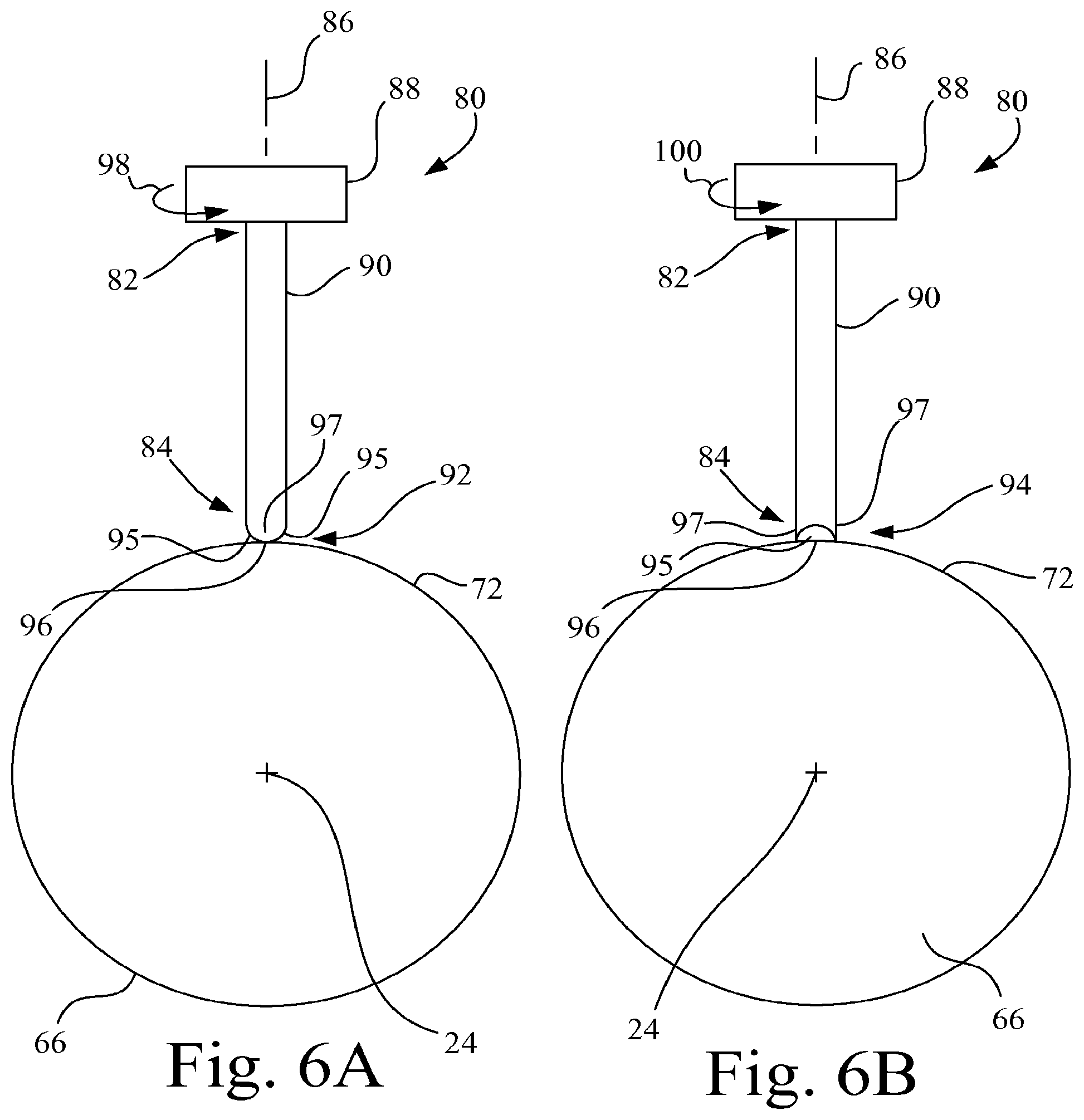
6. A biopsy apparatus, comprising: a housing; a biopsy cannula mounted to the housing, the biopsy cannula having a side wall, a proximal end, a distal end, and a longitudinal axis extending between the proximal end and the distal end, the side wall having an exterior surface and an interior surface, the interior surface of the side wall defining a lumen, and the side wall having a side port proximal to the distal end that extends through the side wall to the lumen; a cannula rotation mechanism mounted to the housing, the cannula rotation mechanism having a thumbwheel, a first gear, and a second gear, the thumbwheel configured to rotate about a rotational axis, the rotational axis being perpendicular to the longitudinal axis of the biopsy cannula, the first gear mounted in fixed attachment to the thumbwheel, the second gear mounted in fixed attachment to the exterior surface of the side wall of the biopsy cannula, and the first gear being in mesh with the second gear such that the first gear is directly drivably engaged with the second gear to rotate the biopsy cannula about the longitudinal axis when the thumbwheel is rotated; a detent wheel mounted in fixed attachment to the biopsy cannula, the detent wheel having a plurality of detent recesses positioned about the longitudinal axis at predetermined angular positions; and a lock mechanism mounted to the housing, the lock mechanism including a locking pin biased along a locking axis in constant engagement with the detent wheel, the locking pin including an engagement end having a tapered portion and a non-tapered portion angularly offset from the tapered portion about the locking axis, the locking pin having a first position and a second position, wherein: in the first position the tapered portion sequentially passes into and out of a respective detent recess of the plurality of detent recesses of the detent wheel as the biopsy cannula is rotated thereby providing at least one of aural, visual and tactile feedback of a progressive rotation of the biopsy cannula, and in the second position the engagement end rides against the detent wheel and the non-tapered portion lockably engages a next detent recess of the plurality of detent recesses of the detent wheel as the biopsy cannula is rotated to lock the biopsy cannula from further rotation.
7. A biopsy apparatus, comprising: a housing; a biopsy cannula mounted to the housing, the biopsy cannula having a side wall, a proximal end, a distal end, and a longitudinal axis extending between the proximal end and the distal end, the side wall having an exterior surface and an interior surface, the interior surface of the side wall defining a lumen, and the side wall having a side port proximal to the distal end that extends through the side wall to the lumen; a cannula rotation mechanism mounted to the housing, the cannula rotation mechanism having a thumbwheel, a first gear, and a second gear, the thumbwheel configured to rotate about a rotational axis, the rotational axis being perpendicular to the longitudinal axis of the biopsy cannula, the first gear mounted in fixed attachment to the thumbwheel, the second gear mounted in fixed attachment to the exterior surface of the side wall of the biopsy cannula, and the first gear being in mesh with the second gear such that the first gear is directly drivably engaged with the second gear to rotate the biopsy cannula about the longitudinal axis when the thumbwheel is rotated; a detent wheel mounted in fixed attachment to the biopsy cannula for coaxial rotation with the biopsy cannula about the longitudinal axis, the detent wheel having a circumferential surface and a plurality of detent recesses formed through the circumferential surface and extending radially toward the longitudinal axis, the plurality of detent recesses being positioned about the longitudinal axis at predetermined angular positions; and a lock mechanism having a locking pin biased along a locking axis in constant engagement with the detent wheel, the locking pin including an engagement end having a tapered portion and a non-tapered portion angularly offset from the tapered portion about the locking axis, the locking pin having a first rotational position relative to the locking axis wherein the engagement end rides along the circumferential surface of the detent wheel and the tapered portion sequentially passes into and out of a respective detent recess of the plurality of detent recesses of the detent wheel as the biopsy cannula is rotated thereby providing at least one of aural, visual and tactile feedback of a progressive rotation of the biopsy cannula, and the locking pin having a second rotational position relative to the locking axis wherein the engagement end rides along the circumferential surface of the detent wheel and the non-tapered portion lockably engages a next detent recess of the plurality of detent recesses of the detent wheel as the biopsy cannula is rotated to lock the biopsy cannula from further rotation.
8. A biopsy apparatus, comprising: a driver assembly having a housing configured to be grasped by a user; a biopsy probe drivably coupled to the driver assembly, the biopsy probe including a biopsy cannula having a cylindrical side wall, a proximal end, a distal end and a longitudinal axis extending between the proximal end and the distal end, the cylindrical side wall defining a lumen and having a side port located near the distal end that extends through the side wall to the lumen; a cannula rotation mechanism mounted to the housing, the cannula rotation mechanism having a thumbwheel, a first gear, and a second gear, the thumbwheel configured to rotate about a rotational axis, the rotational axis being perpendicular to the longitudinal axis of the biopsy cannula, the first gear mounted in fixed attachment to the thumbwheel, the second gear mounted in fixed attachment to the biopsy cannula, and the first gear being in mesh with the second gear such that the first gear is directly drivably engaged with the second gear to rotate the biopsy cannula about the longitudinal axis when the thumbwheel is rotated; a detent wheel mounted in fixed attachment to the biopsy cannula, the detent wheel having a plurality of detent recesses positioned about the longitudinal axis at predetermined angular positions; and an engagement element biased by a spring to be in constant engagement with the detent wheel to sequentially engage each of the plurality of detent recesses to produce at least one of tactile and aural feedback each time the engagement element engages one of the plurality of detent recesses.
9. The biopsy apparatus of claim 8, wherein the biopsy probe is configured for releasable attachment to the housing.
10. The biopsy apparatus of claim 8, configured such that a user rotates the thumbwheel while grasping the housing to effect a manual rotation of the biopsy cannula to position the side port of the biopsy cannula at a desired rotational position about the longitudinal axis.
11. A biopsy apparatus, comprising: a driver assembly having a housing configured to be grasped by a user; a biopsy probe drivably coupled to the driver assembly, the biopsy probe including a biopsy cannula having a cylindrical side wall, a proximal end, a distal end and a longitudinal axis extending between the proximal end and the distal end, the cylindrical side wall defining a lumen and having a side port located near the distal end that extends through the side wall to the lumen; a cannula rotation mechanism mounted to the housing, the cannula rotation mechanism having a thumbwheel, a first gear, and a second gear, the thumbwheel configured to rotate about a rotational axis, the rotational axis being perpendicular to the longitudinal axis of the biopsy cannula, the first gear mounted in fixed attachment to the thumbwheel, the second gear mounted in fixed attachment to the biopsy cannula, and the first gear being in mesh with the second gear such that the first gear is directly drivably engaged with the second gear to rotate the biopsy cannula about the longitudinal axis when the thumbwheel is rotated; a detent wheel mounted in fixed attachment to the biopsy cannula, the detent wheel having a plurality of detent recesses positioned about the longitudinal axis at predetermined angular positions; an engagement element biased in constant engagement with the detent wheel to sequentially engage each of the plurality of detent recesses to produce at least one of tactile and aural feedback each time the engagement element engages one of the plurality of detent recesses; and a lock mechanism mounted to the housing, the lock mechanism including a locking pin biased along a locking axis in constant engagement with the detent wheel, the locking pin including an engagement end having a tapered portion and a non-tapered portion angularly offset from the tapered portion about the locking axis, the locking pin having a first position and a second position, wherein: in the first position the tapered portion sequentially passes into and out of a respective detent recess of the plurality of detent recesses of the detent wheel as the biopsy cannula is rotated thereby providing at least one of aural, visual and tactile feedback of a progressive rotation of the biopsy cannula, and in the second position the engagement end rides along the detent wheel and the non-tapered portion lockably engages a next detent recess of the plurality of detent recesses of the detent wheel as the biopsy cannula is rotated to lock the biopsy cannula from further rotation.
12. A biopsy apparatus, comprising: a driver assembly having a housing configured to be grasped by a user; a biopsy probe drivably coupled to the driver assembly, the biopsy probe including a biopsy cannula having a cylindrical side wall, a proximal end, a distal end and a longitudinal axis extending between the proximal end and the distal end, the cylindrical side wall defining a lumen and having a side port located near the distal end that extends through the side wall to the lumen; a cannula rotation mechanism mounted to the housing, the cannula rotation mechanism having a thumbwheel, a first gear, and a second gear, the thumbwheel configured to rotate about a rotational axis, the rotational axis being perpendicular to the longitudinal axis of the biopsy cannula, the first gear mounted in fixed attachment to the thumbwheel, the second gear mounted in fixed attachment to the biopsy cannula, and the first gear being in mesh with the second gear such that the first gear is directly drivably engaged with the second gear to rotate the biopsy cannula about the longitudinal axis when the thumbwheel is rotated; a detent wheel mounted in fixed attachment to the biopsy cannula for coaxial rotation with the biopsy cannula about the longitudinal axis, the detent wheel having a circumferential surface and a plurality of detent recesses formed through the circumferential surface and extending radially toward the longitudinal axis, the plurality of detent recesses being positioned about the longitudinal axis at predetermined angular positions; and a lock mechanism having a locking pin biased along a locking axis in constant engagement with the detent wheel, the locking pin including an engagement end having a tapered portion and a non-tapered portion angularly offset from the tapered portion about the locking axis, the locking pin having a first rotational position relative to the locking axis wherein the engagement end rides along the circumferential surface of the detent wheel and the tapered portion sequentially passes into and out of a respective detent recess of the plurality of detent recesses of the detent wheel as the biopsy cannula is rotated thereby providing at least one of aural, visual and tactile feedback of a progressive rotation of the biopsy cannula, and the locking pin having a second rotational position relative to the locking axis wherein the engagement end rides along the circumferential surface of the detent wheel and the non-tapered portion lockably engages a next detent recess of the plurality of detent recesses of the detent wheel as the biopsy cannula is rotated to lock the biopsy cannula from further rotation.
Description
BACKGROUND OF THE INVENTION
1. Field of the Invention
The present invention relates to a biopsy apparatus, and, more particularly, to a biopsy apparatus having an integrated thumbwheel mechanism for manual rotation of a biopsy cannula.
2. Description of the Related Art
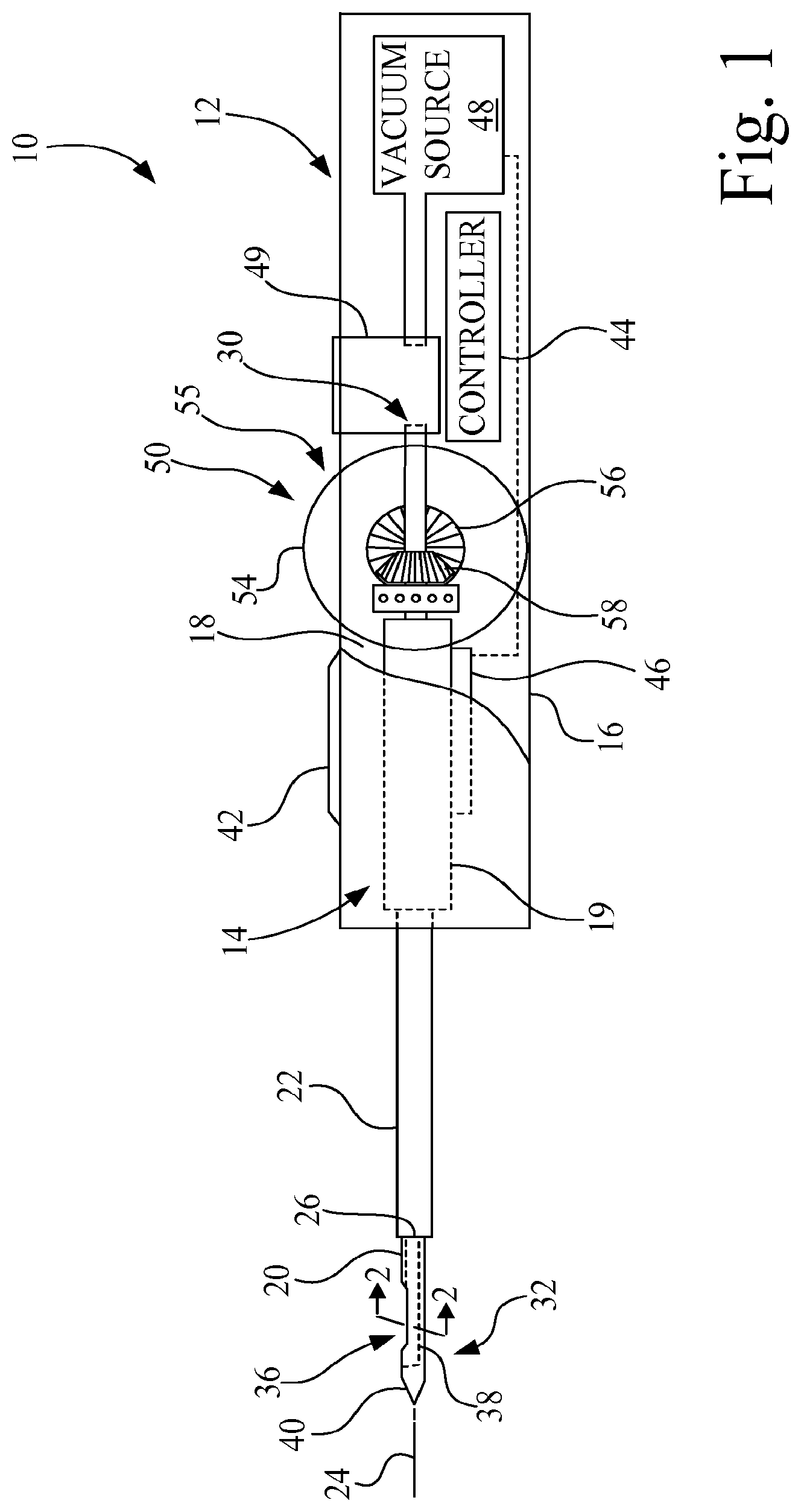
A biopsy may be performed on a patient to help in determining whether the cells in a biopsied region are cancerous. One biopsy technique used to evaluate breast tissue, for example, involves inserting a biopsy probe into the breast tissue region of interest to capture one or more tissue samples from the region. Such a biopsy technique often utilizes a vacuum to pull the tissue to be sampled into a sample notch of the biopsy probe, after which the tissue is severed and collected. One type of vacuum assisted biopsy apparatus includes a hand-held driver assembly having a vacuum source, and a disposable biopsy probe assembly configured for releasable attachment to the driver assembly. The biopsy probe typically includes a biopsy cannula, e.g., a needle, having a side port for receiving the tissue to be sampled.
During a biopsy procedure, it may be desirable to position the side port to various angular positions around a longitudinal axis of the biopsy cannula without having to rotate the hand-held driver assembly. One console-type biopsy device includes a control console tethered to a hand-held driver assembly, wherein the control module is programmed to provide automatic indexing of the side port to predetermined angular positions. However, such automatic indexing may limit the ability of the physician to make real-time changes and/or minute changes to the angular position of the side port.
Also, it is known to provide manual indexing of the side port of the biopsy cannula by attaching a knob to the distal end of the biopsy cannula, and then simply rotate the knob to position the side port to the desired angular position. One disadvantage, however, is that such an arrangement requires the physician to hold the handle of the hand-held driver assembly in one hand, while rotating the knob with the other hand.
SUMMARY OF THE INVENTION
The present invention provides a biopsy apparatus having a mechanism that enables a user to operate the biopsy apparatus and manually rotate a side port of a biopsy cannula to a desired rotational position about the longitudinal axis relative to the driver assembly through a single-handed operation of the biopsy apparatus. Mechanisms may also provide at least one of tactile, aural and visual feedback of the rotation of the biopsy cannula, as well as facilitate the selective locking of the biopsy cannula from further rotation so as to maintain a current rotational position of the side port of the biopsy cannula during the harvesting of a tissue sample.
As used herein, the terms "first" and "second" preceding an element name, e.g., first gear, second gear, etc., are for identification purposes to distinguish between different elements having similar characteristic, and are not intended to necessarily imply order, unless otherwise specified, nor are the terms "first" and "second" intended to preclude the inclusion of additional similar elements.
The invention in one form is directed to a biopsy apparatus. The biopsy apparatus includes a driver assembly having a housing configured to be grasped by a user. A biopsy probe mechanism is drivably coupled to the driver assembly. The biopsy probe mechanism includes a biopsy cannula having a cylindrical side wall, a proximal end, a distal end and a longitudinal axis extending between the proximal end and the distal end. The cylindrical side wall defines a lumen and has a side port located near the distal end that extends through the side wall to the lumen. A thumbwheel mechanism includes a thumbwheel mounted to the driver assembly to rotate about a first rotational axis, the first rotational axis being substantially perpendicular to the longitudinal axis, wherein at least a portion of the thumbwheel is exposed external to the housing. A first gear is mounted to the thumbwheel for coaxial rotation with the thumbwheel about the first rotational axis. A second gear is mounted to the biopsy cannula for coaxial rotation with the biopsy cannula about the longitudinal axis, the second gear being located to be drivably engaged by the first gear. A user grasps the housing and rotates the thumbwheel with a single hand to rotatably position the side port of the biopsy cannula at a desired rotational position about the longitudinal axis relative to the driver assembly.
The invention in another form is
D00000
D00001
D00002
D00003
D00004
D00005
XML
uspto.report is an independent third-party trademark research tool that is not affiliated, endorsed, or sponsored by the United States Patent and Trademark Office (USPTO) or any other governmental organization. The information provided by uspto.report is based on publicly available data at the time of writing and is intended for informational purposes only.
While we strive to provide accurate and up-to-date information, we do not guarantee the accuracy, completeness, reliability, or suitability of the information displayed on this site. The use of this site is at your own risk. Any reliance you place on such information is therefore strictly at your own risk.
All official trademark data, including owner information, should be verified by visiting the official USPTO website at www.uspto.gov. This site is not intended to replace professional legal advice and should not be used as a substitute for consulting with a legal professional who is knowledgeable about trademark law.