Forced convection steam assembly
Mayberry Oc
U.S. patent number 10,451,290 [Application Number 15/451,760] was granted by the patent office on 2019-10-22 for forced convection steam assembly. This patent grant is currently assigned to WHIRLPOOL CORPORATION. The grantee listed for this patent is WHIRLPOOL CORPORATION. Invention is credited to Timothy A. Mayberry.


| United States Patent | 10,451,290 |
| Mayberry | October 22, 2019 |
Forced convection steam assembly
Abstract
A convection oven includes a convection fan assembly and a trough assembly that surrounds a portion of the heating element(s) of the convection fan assembly. Fluid in the trough assembly is heated and turned into steam by the heating element(s) and blown into the cooking cavity of the convection oven by the convection fan of the convection fan assembly. The steam in the cooking cavity provides moisture to the items that are being cooked and/or heated in the cooking cavity.
| Inventors: | Mayberry; Timothy A. (St. Joseph, MI) | ||||||||||
|---|---|---|---|---|---|---|---|---|---|---|---|
| Applicant: |
|
||||||||||
| Assignee: | WHIRLPOOL CORPORATION (Benton
Harbor, MI) |
||||||||||
| Family ID: | 61283021 | ||||||||||
| Appl. No.: | 15/451,760 | ||||||||||
| Filed: | March 7, 2017 |
Prior Publication Data
| Document Identifier | Publication Date | |
|---|---|---|
| US 20180259192 A1 | Sep 13, 2018 | |
| Current U.S. Class: | 1/1 |
| Current CPC Class: | F24C 15/003 (20130101); F24C 15/327 (20130101) |
| Current International Class: | F24C 15/00 (20060101); F24C 15/32 (20060101) |
| Field of Search: | ;219/401 |
References Cited [Referenced By]
U.S. Patent Documents
| 1141176 | June 1915 | Copeman |
| 1380656 | June 1921 | Lauth |
| 1405624 | February 1922 | Patterson |
| 1598996 | September 1926 | Wheelock |
| 1808550 | June 1931 | Harpman |
| 2024510 | December 1935 | Crisenberry |
| 2530991 | November 1950 | Reeves |
| 2536613 | January 1951 | Schulze et al. |
| 2777407 | January 1957 | Schindler |
| 2781038 | February 1957 | Sherman |
| 2815018 | December 1957 | Collins |
| 2828608 | April 1958 | Cowlin et al. |
| 2847932 | August 1958 | More |
| 2930194 | May 1960 | Perkins |
| 2934957 | May 1960 | Reinhart et al. |
| D191085 | August 1961 | Kindl et al. |
| 3017924 | January 1962 | Jenson |
| 3051813 | August 1962 | Busch et al. |
| 3089407 | May 1963 | Kinkle |
| 3259120 | July 1966 | Keating |
| 3386431 | June 1968 | Branson |
| 3463138 | August 1969 | Lotter et al. |
| 3489135 | January 1970 | Astrella |
| 3548154 | December 1970 | Christiansson |
| 3602131 | August 1971 | Dadson |
| 3691937 | September 1972 | Meek et al. |
| 3731035 | May 1973 | Jarvis et al. |
| 3777985 | December 1973 | Hughes et al. |
| 3780954 | December 1973 | Genbauffs |
| 3857254 | December 1974 | Lobel |
| 3877865 | April 1975 | Duperow |
| 3899655 | August 1975 | Skinner |
| D245663 | September 1977 | Gordon |
| 4149518 | April 1979 | Schmidt et al. |
| 4363956 | December 1982 | Scheidler et al. |
| 4413610 | November 1983 | Berlik |
| 4418456 | December 1983 | Riehl |
| 4447711 | May 1984 | Fischer |
| 4466789 | August 1984 | Riehl |
| 4518346 | May 1985 | Pistien |
| 4587946 | May 1986 | Doyon et al. |
| 4646963 | March 1987 | Delotto et al. |
| 4654508 | March 1987 | Logel et al. |
| 4689961 | September 1987 | Stratton |
| 4812624 | March 1989 | Kern |
| 4846671 | July 1989 | Kwiatek |
| 4886043 | December 1989 | Homer |
| 4891936 | January 1990 | Shekleton et al. |
| D309398 | July 1990 | Lund |
| 4981416 | January 1991 | Nevin et al. |
| 4989404 | February 1991 | Shekleton |
| 5136277 | August 1992 | Civanelli et al. |
| 5171951 | December 1992 | Chartrain et al. |
| D332385 | January 1993 | Adams |
| 5190026 | March 1993 | Doty |
| D340383 | October 1993 | Addison et al. |
| 5272317 | December 1993 | Ryu |
| D342865 | January 1994 | Addison et al. |
| 5397234 | March 1995 | Kwiatek |
| D364993 | December 1995 | Andrea |
| 5491423 | February 1996 | Turetta |
| D369517 | May 1996 | Ferlin |
| 5546927 | August 1996 | Lancelot |
| D378578 | March 1997 | Eberhardt |
| 5618458 | April 1997 | Thomas |
| 5649822 | July 1997 | Gertler et al. |
| 5735261 | April 1998 | Kieslinger |
| 5785047 | July 1998 | Bird et al. |
| 5842849 | December 1998 | Huang |
| 5913675 | June 1999 | Vago et al. |
| 5928540 | July 1999 | Antoine et al. |
| D414377 | September 1999 | Huang |
| 5967021 | October 1999 | Yung |
| 6030207 | February 2000 | Saleri |
| 6050176 | April 2000 | Schultheis et al. |
| 6089219 | July 2000 | Kodera et al. |
| 6092518 | July 2000 | Dane |
| 6111229 | August 2000 | Schultheis |
| 6114665 | September 2000 | Garcia et al. |
| 6155820 | December 2000 | Dobbeling |
| 6188045 | February 2001 | Hansen et al. |
| 6192669 | February 2001 | Keller et al. |
| 6196113 | March 2001 | Yung |
| 6253759 | July 2001 | Giebel et al. |
| 6320169 | November 2001 | Clothier |
| 6322354 | November 2001 | Carbone et al. |
| 6362458 | March 2002 | Sargunam et al. |
| 6452136 | September 2002 | Berkcan et al. |
| 6452141 | September 2002 | Shon |
| 6589046 | July 2003 | Harneit |
| 6614006 | September 2003 | Pastore et al. |
| 6619280 | September 2003 | Zhou et al. |
| 6655954 | December 2003 | Dane |
| 6663009 | December 2003 | Bedetti et al. |
| 6718965 | April 2004 | Rummel et al. |
| 6837151 | January 2005 | Chen |
| 6891133 | May 2005 | Shozo et al. |
| 6930287 | August 2005 | Gerola et al. |
| 7005614 | February 2006 | Lee |
| 7017572 | March 2006 | Cadima |
| D524105 | July 2006 | Poltronieri |
| 7083123 | August 2006 | Molla |
| 7220945 | May 2007 | Wang |
| D544753 | June 2007 | Tseng |
| 7274008 | September 2007 | Arnal Valero et al. |
| 7281715 | October 2007 | Boswell |
| 7291009 | November 2007 | Kamal et al. |
| 7325480 | February 2008 | Gruhbaum et al. |
| D564296 | March 2008 | Koch et al. |
| 7348520 | March 2008 | Wang |
| 7368685 | May 2008 | Nam et al. |
| 7411160 | August 2008 | Duncan et al. |
| 7417204 | August 2008 | Nam et al. |
| D581736 | December 2008 | Besseas |
| 7468496 | December 2008 | Marchand |
| D592445 | May 2009 | Sorenson et al. |
| D598959 | August 2009 | Kiddoo |
| 7589299 | September 2009 | Fisher et al. |
| D604098 | November 2009 | Hamlin |
| 7614877 | November 2009 | McCrorey et al. |
| 7628609 | December 2009 | Pryor et al. |
| 7640930 | January 2010 | Little et al. |
| 7696454 | April 2010 | Nam et al. |
| 7708008 | May 2010 | Elkasevic et al. |
| 7721727 | May 2010 | Kobayashi |
| 7731493 | June 2010 | Starnini et al. |
| 7762250 | July 2010 | Elkasevic et al. |
| 7770985 | August 2010 | Davis et al. |
| 7781702 | August 2010 | Nam et al. |
| 7823502 | November 2010 | Hecker et al. |
| 7829825 | November 2010 | Kuhne |
| 7841333 | November 2010 | Kobayashi |
| 7964823 | June 2011 | Armstrong et al. |
| D642675 | August 2011 | Scribano et al. |
| 8006687 | August 2011 | Watkins et al. |
| 8015821 | September 2011 | Spytek |
| 8037689 | October 2011 | Oskin et al. |
| 8141549 | March 2012 | Armstrong et al. |
| 8217314 | July 2012 | Kim et al. |
| 8220450 | July 2012 | Luo et al. |
| 8222578 | July 2012 | Beier |
| D665491 | August 2012 | Goel et al. |
| 8272321 | September 2012 | Kalsi et al. |
| 8288690 | October 2012 | Boubeddi et al. |
| 8302593 | November 2012 | Cadima |
| 8304695 | November 2012 | Bonuso et al. |
| 8342165 | January 2013 | Watkins |
| 8393317 | March 2013 | Sorenson et al. |
| 8398303 | March 2013 | Kuhn |
| 8464703 | June 2013 | Ryu et al. |
| D685225 | July 2013 | Santoyo et al. |
| D687675 | August 2013 | Filho et al. |
| 8535052 | September 2013 | Cadima |
| D693175 | November 2013 | Saubert |
| 8584663 | November 2013 | Kim et al. |
| 8596259 | December 2013 | Padgett et al. |
| 8616193 | December 2013 | Padgett |
| 8660297 | February 2014 | Yoon et al. |
| 8687842 | April 2014 | Yoon et al. |
| 8707945 | April 2014 | Hasslberger et al. |
| 8747108 | June 2014 | Lona Santoyo et al. |
| 8800543 | August 2014 | Simms et al. |
| D718061 | November 2014 | Wu |
| 8887710 | November 2014 | Rossi et al. |
| 8930160 | January 2015 | Wall et al. |
| 8932049 | January 2015 | Ryu et al. |
| 8950389 | February 2015 | Horstkoetter et al. |
| 8978637 | March 2015 | Ryu et al. |
| D727489 | April 2015 | Rohskopf et al. |
| 9021942 | May 2015 | Lee et al. |
| 9074765 | July 2015 | Armanni |
| D735525 | August 2015 | Nguyen |
| 9113503 | August 2015 | Arnal Valero et al. |
| 9132302 | September 2015 | Luongo et al. |
| D743203 | November 2015 | Filho et al. |
| 9175858 | November 2015 | Tisselli et al. |
| D750314 | February 2016 | Hobson et al. |
| 9307888 | April 2016 | Baldwin et al. |
| D758107 | June 2016 | Hamilton |
| D766036 | September 2016 | Koch et al. |
| D766696 | September 2016 | Kemker |
| 9513015 | December 2016 | Estrella et al. |
| 9521708 | December 2016 | Adelmann et al. |
| 9572475 | February 2017 | Gephart et al. |
| 9644847 | May 2017 | Bhogal et al. |
| 9696042 | July 2017 | Hasslberger et al. |
| 9927129 | March 2018 | Bhogal et al. |
| 2002/0065039 | May 2002 | Benezech et al. |
| 2004/0031782 | February 2004 | Westfield |
| 2004/0195399 | October 2004 | Molla |
| 2004/0224273 | November 2004 | Inomata |
| 2004/0224274 | November 2004 | Tomiura |
| 2005/0112520 | May 2005 | Todoli et al. |
| 2005/0199232 | September 2005 | Gama et al. |
| 2005/0268794 | December 2005 | Nesterov |
| 2007/0124972 | June 2007 | Ratcliffe |
| 2007/0251936 | November 2007 | Nam et al. |
| 2007/0281267 | December 2007 | Li |
| 2008/0029081 | February 2008 | Gagas et al. |
| 2008/0050687 | February 2008 | Wu |
| 2008/0173632 | July 2008 | Jang et al. |
| 2008/0210685 | September 2008 | Beier |
| 2009/0320823 | December 2009 | Padgett |
| 2010/0035197 | February 2010 | Cadima |
| 2010/0126496 | May 2010 | Luo et al. |
| 2010/0154776 | June 2010 | Czajka et al. |
| 2010/0192939 | August 2010 | Parks |
| 2011/0027733 | February 2011 | Yamamoto et al. |
| 2011/0142998 | June 2011 | Johncock et al. |
| 2011/0163086 | July 2011 | Aldana Arjol et al. |
| 2011/0248021 | October 2011 | Gutierrez et al. |
| 2012/0017595 | January 2012 | Liu |
| 2012/0036855 | February 2012 | Hull |
| 2012/0067334 | March 2012 | Kim et al. |
| 2012/0076351 | March 2012 | Yoon et al. |
| 2012/0099761 | April 2012 | Yoon et al. |
| 2012/0160228 | June 2012 | Kim et al. |
| 2012/0171343 | July 2012 | Cadima et al. |
| 2012/0261405 | October 2012 | Kurose et al. |
| 2013/0043239 | February 2013 | Anton Falcon et al. |
| 2013/0252188 | September 2013 | Chen |
| 2013/0255663 | October 2013 | Cadima et al. |
| 2013/0260618 | October 2013 | Bally et al. |
| 2014/0048055 | February 2014 | Ruther |
| 2014/0090636 | April 2014 | Bettinzoli |
| 2014/0097172 | April 2014 | Kang et al. |
| 2014/0116416 | May 2014 | Saubert |
| 2014/0137751 | May 2014 | Bellm |
| 2014/0139381 | May 2014 | Sippel |
| 2014/0318527 | October 2014 | Silva et al. |
| 2015/0096974 | April 2015 | Freeman et al. |
| 2015/0136760 | May 2015 | Lima et al. |
| 2015/0153041 | June 2015 | Neumeier |
| 2015/0241069 | August 2015 | Brant et al. |
| 2015/0330640 | November 2015 | Stork genannt Wersborg |
| 2015/0345800 | December 2015 | Cabrera Botello |
| 2015/0359045 | December 2015 | Neukamm et al. |
| 2016/0029439 | January 2016 | Kurose et al. |
| 2016/0061490 | March 2016 | Cho et al. |
| 2016/0095469 | April 2016 | Gregory et al. |
| 2016/0116160 | April 2016 | Takeuchi |
| 2016/0153666 | June 2016 | Tcaciuc |
| 2016/0178209 | June 2016 | Park et al. |
| 2016/0178212 | June 2016 | Park et al. |
| 2016/0187002 | June 2016 | Ryu et al. |
| 2016/0201902 | July 2016 | Cadima |
| 2016/0209044 | July 2016 | Cadima |
| 2016/0295644 | October 2016 | Khokle et al. |
| 2016/0296067 | October 2016 | Laws |
| 2017/0003033 | January 2017 | Lona Santoyo et al. |
| 2017/0067651 | March 2017 | Khokle et al. |
| 2017/0082296 | March 2017 | Jeong et al. |
| 2017/0082299 | March 2017 | Rowley et al. |
| 2017/0103228 | April 2017 | Park et al. |
| 2017/0115008 | April 2017 | Erbe et al. |
| 2017/0223774 | August 2017 | Cheng et al. |
| 2017/0261213 | September 2017 | Park et al. |
| 2018/0058702 | March 2018 | Jang et al. |
| 2365023 | Jul 2002 | CA | |||
| 2734926 | Oct 2011 | CA | |||
| 201680430 | Dec 2010 | CN | |||
| 2845869 | Apr 1980 | DE | |||
| 3014908 | Oct 1981 | DE | |||
| 3238441 | Apr 1984 | DE | |||
| 3446621 | Jun 1986 | DE | |||
| 3839657 | May 1990 | DE | |||
| 4103664 | Jan 1992 | DE | |||
| 4445594 | Jun 1996 | DE | |||
| 60004581 | Jun 2004 | DE | |||
| 102004002466 | Aug 2005 | DE | |||
| 102005059505 | Jun 2007 | DE | |||
| 102005059505 | Jun 2007 | DE | |||
| 102007021297 | Nov 2008 | DE | |||
| 102008042467 | Apr 2010 | DE | |||
| 102008051829 | Apr 2010 | DE | |||
| 102008051829 | Apr 2010 | DE | |||
| 102013218714 | Apr 2014 | DE | |||
| 0000908 | Mar 1979 | EP | |||
| 0000908 | Mar 1979 | EP | |||
| 0122966 | Oct 1984 | EP | |||
| 0429120 | Nov 1990 | EP | |||
| 0690659 | Jan 1996 | EP | |||
| 1030114 | Aug 2000 | EP | |||
| 1217306 | Jun 2002 | EP | |||
| 1344986 | Sep 2003 | EP | |||
| 1617148 | Jan 2006 | EP | |||
| 1617148 | Jan 2006 | EP | |||
| 1201998 | Mar 2006 | EP | |||
| 1460342 | May 2006 | EP | |||
| 2116775 | Nov 2009 | EP | |||
| 2116829 | Nov 2009 | EP | |||
| 2276227 | Jan 2011 | EP | |||
| 2299181 | Mar 2011 | EP | |||
| 2375170 | Oct 2011 | EP | |||
| 2144012 | Sep 2012 | EP | |||
| 2657615 | Oct 2013 | EP | |||
| 2816291 | Dec 2014 | EP | |||
| 2835580 | Feb 2015 | EP | |||
| 3006832 | Apr 2016 | EP | |||
| 2789753 | Aug 2000 | FR | |||
| 3003338 | Sep 2014 | FR | |||
| 2158225 | Nov 1985 | GB | |||
| 2010038475 | Feb 2010 | JP | |||
| 2011144982 | Jul 2011 | JP | |||
| 2006136363 | Dec 2006 | WO | |||
| 2012077050 | Jun 2012 | WO | |||
| 2013098330 | Jul 2013 | WO | |||
| 2013104521 | Jul 2013 | WO | |||
| 2013104521 | Jul 2013 | WO | |||
| WO-2013104521 | Jul 2013 | WO | |||
| 2013182410 | Dec 2013 | WO | |||
| 2014194176 | Dec 2014 | WO | |||
| 2015086420 | Jun 2015 | WO | |||
Other References
|
Built-In Gas Cooktop, image post date Feb. 18, 2015, originally in U.S. Appl. No. 29/539,768 in Restriction Requirement dated Oct. 27, 2016, 10 pages, <http://www.bestbuy.com/site/kitchenaid-36-built-in-gas-cooktop- -stainless-steel/8636634.p?skuld=8636634>. cited by applicant . True-Heat burner, image post date Jan. 30, 2015, originally in U.S. Appl. No. 29/539,768 in Restriction Requirement dated Oct. 27, 2016, 2 pages, <http://ovens.reviewed.com/news/kitchenaid-has-a-new-flame>. cited by applicant . Metal Cover Gas Hob, image post date 2012, originally in U.S. Appl. No. 29/539,768 in Restriction Requirement dated Oct. 27, 2016, 13 pages, <http://inse.gmc.globalmarket.com/products/details/metal-cover-gas-hob- -8516959.html>. cited by applicant . Penny Stove, image post date 2004, originally in U.S. Appl. No. 29/539,768 in Restriction Requirement dated Oct. 27, 2016, 30 pages, <http://www.jureystudio.com/pennystove/stoveinstruction.html>. cited by applicant. |
Primary Examiner: Savani; Avinash A
Assistant Examiner: Heyamoto; Aaron H
Attorney, Agent or Firm: Price Heneveld LLP
Claims
What is claimed:
1. An oven comprising: an oven housing defining a cooking cavity; a door coupled to the housing; a convection fan assembly comprising a convection fan with a fan blade and at least one generally cylindrical heating element surrounding said blade to heat up the air in the cooking cavity; a trough assembly comprising an open trough tray portion having walls surrounding a portion of said at least one generally cylindrical heating element, and a trough supply portion shaped to receive fluid and direct it to the trough tray portion so that it can be heated and turned into steam by said at least one generally cylindrical heating element and blown into said cooking cavity by said convection fan.
2. The oven of claim 1, wherein: said trough assembly is manually filled with fluid.
3. The oven of claim 1, wherein: said trough tray portion and said trough supply portion are connected.
4. The oven of claim 1, wherein: said trough assembly is filled with fluid by a drip ball valve positioned above said trough supply portion of said trough assembly.
5. The oven of claim 4, wherein: said drip ball valve is controlled electronically.
6. The oven of claim 1, wherein: said trough assembly is filled with fluid by a fluid line connected to a solenoid valve.
7. The oven of claim 1, wherein: said fluid is water with an additive.
8. The oven of claim 1, including: a fluid delivery system that has a conduction break to prevent heat from travelling to at least one valve in said fluid delivery system.
Description
BACKGROUND
Generally, a convection oven includes a convection fan that is near one or more heating elements. The heating element heats air which is blown into the cooking cavity of the oven by the convection fan. While the convection fan is useful to heat and/or cook an item within the cooking cavity, the heated air blown into the cooking cavity can make the item very dry. Stand-alone steam systems are very large and costly to integrate into a cooking appliance. For example, a powered boiler is large, expensive, and requires welding and additional electrical power which may require sharing power with the heating elements and/or the convection fan motor. Thus, it is desirable to have a convection oven that has a smaller, less-expensive approach to provide moisture into the cooking cavity to help keep the item in the cooking cavity moist.
SUMMARY OF THE INVENTION
One aspect of the present invention is an oven with a housing defining a cooking cavity. The oven has a door coupled to the housing. The oven has a convection fan assembly with a convection fan and at least one heating element to generate heat and to heat the air in the cooking cavity. The oven also has a trough assembly with a trough tray portion located underneath a portion of the convection fan and the convection fan heating element. The trough assembly also includes a trough supply portion shaped to receive fluid and to direct the fluid to the trough tray portion so that the fluid can be heated and turned into steam by the heating element(s) and blown into the cooking cavity by the convection fan.
Another aspect of the present invention is a convection fan assembly with a steaming device. The convection fan assembly has a convection fan connected to a motor that rotates the convection fan and at least one generally annular heating element coupled near the convection fan. The convection fan assembly also has a trough assembly. The trough assembly has a trough tray located underneath a portion of the convection fan and the generally annular heating element(s). The trough assembly also has a trough supply portion shaped to receive fluid and to direct the fluid to the trough tray portion so that the fluid can be heated by the generally annular heating element(s) and turned into steam, which is blown by the convection fan.
Another aspect of the present invention is a method for providing steam to a convection oven. The method includes forming a trough tray capable of holding fluid while surrounding a portion of the heating element(s) of the convection oven. The method includes forming a trough supply portion shaped to direct fluid to the trough tray. The method also includes adding fluid to the trough tray so that the fluid can be heated by the heating element(s) of the convection oven and forced into the oven cooking cavity by the fan of the convection oven.
These and other features, advantages, and objects of the present invention will be further understood and appreciated by those skilled in the art upon studying the following specification, claims, and appended drawings.
BRIEF DESCRIPTION OF THE DRAWINGS
In the drawings:
FIG. 1 is a front perspective view of an oven according to an embodiment of the present concept;
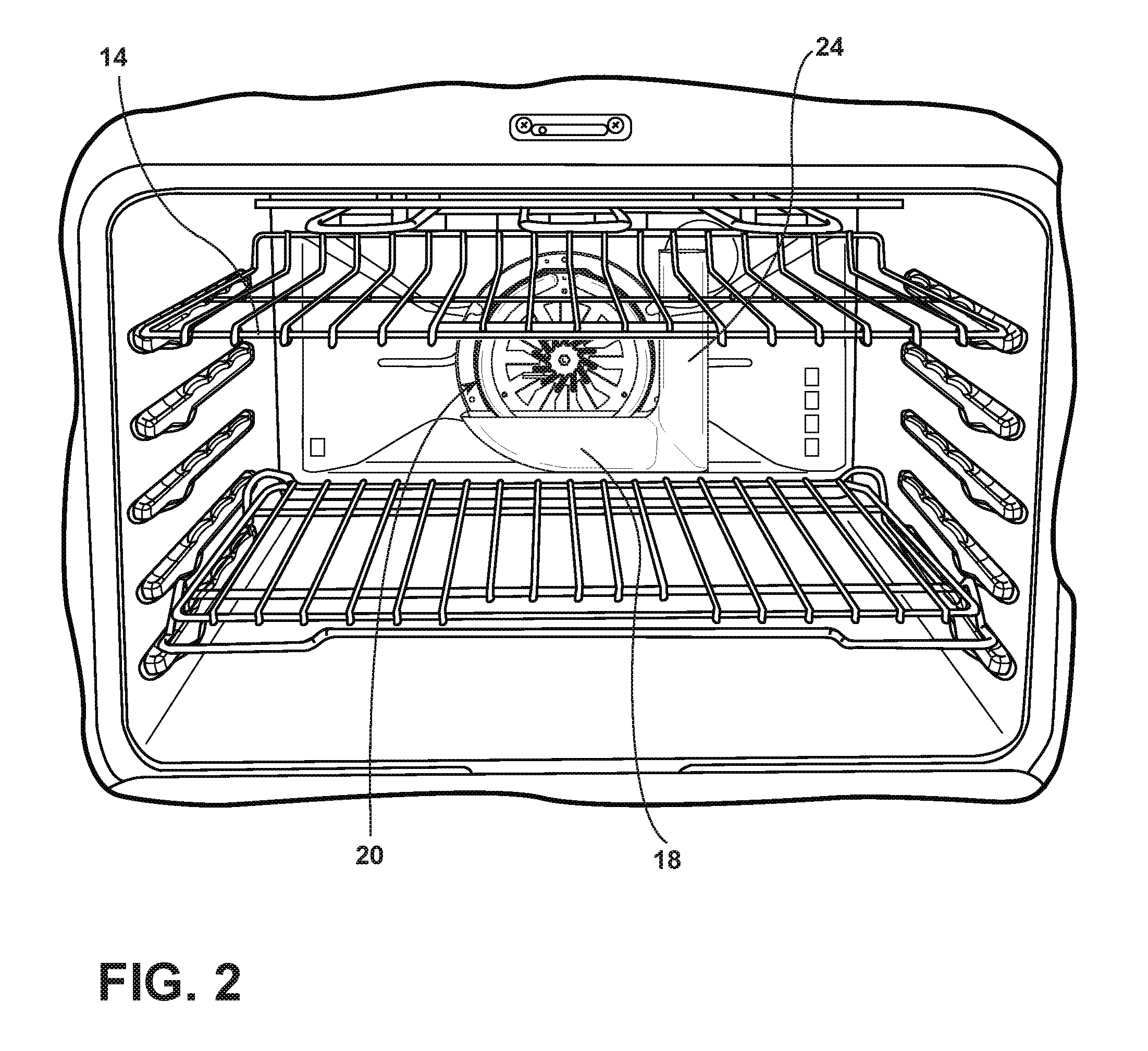
FIG. 2 is a partial front perspective view of the cavity of the oven shown in FIG. 1 with the baffle covering the convection assembly removed;
FIG. 3 is a front perspective view of the convection fan assembly and trough assembly of the oven shown in FIG. 1;
FIG. 4 is front perspective view of the convection fan assembly and trough assembly shown in FIG. 3 before the trough assembly is situated around a portion of the convection fan assembly;
FIG. 5 is a front view of the convection fan assembly and trough assembly showing a drip valve above a portion of the trough assembly; and
FIG. 6 is a partial cross section showing the convection fan assembly, the trough assembly, and fluid supply along with fluid level(s) in the trough assemblies.
DETAILED DESCRIPTION OF THE PREFERRED EMBODIMENTS
As referenced in the figures, the same reference numerals may be used herein to refer to the same parameters and components or their similar modifications and alternatives. For purposes of description herein, the terms "upper," "lower," "right," "left," "rear," "front," "vertical," "horizontal," and derivatives thereof shall relate to the present disclosure as oriented in FIG. 1. However, it is to be understood that the present disclosure may assume various alternative orientations, except where expressly specified to the contrary. It is also to be understood that the specific devices and processes illustrated in the attached drawings, and described in the following specification are simply exemplary embodiments of the inventive concepts defined in the appended claims. Hence, specific dimensions and other physical characteristics relating to the embodiments disclosed herein are not to be considered as limiting, unless the claims expressly state otherwise. The drawings referenced herein are schematic and associated views thereof are not necessarily drawn to scale.
With reference to the drawings, an oven 2 includes a cooking cavity 4 and an oven door 6. The oven door 6 can have a handle 8 to assist in the opening and closing of the oven door 6 for access to the cooking cavity 4. The oven 2 can have a number of burners 10 that are controlled by associated burner controls 12. As illustrated in FIG. 2, the cooking cavity 4 can have one or more racks 14 that are supported by rack supports 16.
The oven 2 includes a convection fan assembly 20 that provides heated air to the cooking cavity 4 to heat and/or cook items within the cooking cavity 4. Typically, a baffle (not shown) is placed over the convection fan assembly 20 to prevent contact with the components of the convection fan assembly 20 when the cooking cavity 4 is used. This baffle has apertures that allow air to pass from the convection fan assembly 20 to the cooking cavity 4.
The convection fan assembly 20 includes a mounting plate 32 that allows the convection fan assembly 20 to be coupled to the cooking cavity 4. The convection fan assembly 20 includes a fan blade 34 that is rotated by a motor coupled to a connection 36. A fastener 38 is used to secure the fan blade 34 to the connection 36.
In the illustrated embodiment, the convection fan assembly 20 has a generally annular heating element(s) 30. These heating element(s) 30 are positioned generally near the fan blade 34 but do not inhibit the movement of the fan blade 34. As illustrated in FIG. 6, the fan motor is powered by electrical connection 48, while the heating element(s) 30 are powered by electrical connection 46.
A trough assembly 18 includes a trough tray portion 22 with an interior 28 and a trough supply portion 24, as illustrated in FIGS. 2-6. While the trough tray portion 22 and trough supply portion 24 are shown as a unitary piece in the illustrated embodiment, they can be separate pieces that are positioned relative to each other.
The trough tray portion 22 is shaped to surround a portion of the convection fan assembly 20, as shown in FIGS. 2-6. When the trough tray portion 22 is situated around the convection fan assembly 20, a portion of the heating element(s) 30 is within the interior 28 of the trough tray portion 22.
The trough supply portion 24 has a generally cylindrical tubular design in the illustrated embodiment. However, the trough supply portion 24 can be of any shape, so long as it can direct fluid to the trough tray portion 22. However, in some embodiments the trough tray portion 22 can be manually filled with fluid and/or have a fluid connection directly to the trough tray portion 22 without the need for a trough supply portion 24.
The trough tray portion 22 and the trough supply portion 24 can be made of the same or different materials. The trough tray portion 22 needs to be made of a material that can withstand the heat generated by the heating element(s) 30. Thus, the trough tray portion 22 can be made of metal or a high temperature-resistant ceramic or polymeric material.
A fluid supply system can be used to supply fluid to the trough tray portion 22. As shown in FIGS. 5 and 6, that fluid supply system can be used in connection with the trough supply portion 24. For example, tube end 40 may be positioned over the interior opening 26 of the trough supply portion 24. The tube 42 extends from a valve 44 to the tube end 40, as illustrated in FIG. 6.
As illustrated in FIG. 6, the fluid level 50 can be below the heating element(s) 30. In this arrangement, the heating element(s) 30 can heat the fluid and turn it into steam to be forced into the cooking cavity 4 by rotation of the fan blade 34. Also as illustrated in FIG. 6, the fluid level 50A can actually cover a portion of the heating element(s) 30. Again, in this arrangement, the heating element(s) 30 will heat the fluid and turn it into steam to be forced into the cooking cavity 4 by rotation of the fan blade 34.
The fluid can be water or water with an additive. For example, the additives could include any number of different flavors, such as liquid smoke, liquid garlic, or any other desired flavor.
The valve 44 can be of any type of valve. For example, it can be a drip ball valve, a solenoid valve, or other type of valve.
The valve 44 may be controlled electronically. For example, the valve 44 can be opened or closed based upon any one or combination of factors, including, but not limited to, the humidity in the cooking cavity 4, the fluid level 50, 50A in the trough tray portion 22, timing, steam percent, etc.
The fluid supply can also include a conduction break to prevent heat transfer to the valve 44. In addition, the fluid supply can have multiple outlets for multiple convection fans.
The heating element(s) 30 can be any type of heating element(s). In the illustrated embodiment, the heating element(s) 30 in a calrod burner that can reach a temperature of approximately 700.degree. C. (1292.degree. F.) which will turn the fluid into steam.
It will be understood by one having ordinary skill in the art that construction of the described device and other components is not limited to any specific material. Other exemplary embodiments of the device disclosed herein may be formed from a wide variety of materials, unless described otherwise herein.
For purposes of this disclosure, the term "coupled" (in all of its forms, couple, coupling, coupled, etc.) generally means the joining of two components (electrical or mechanical) directly or indirectly to one another. Such joining may be stationary in nature or movable in nature. Such joining may be achieved with the two components (electrical or mechanical) and any additional intermediate members being integrally formed as a single unitary body with one another or with the two components. Such joining may be permanent in nature or may be removable or releasable in nature unless otherwise stated.
It is also important to note that the construction and arrangement of the elements of the device as shown in the exemplary embodiments is illustrative only. Although only a few embodiments of the present innovations have been described in detail in this disclosure, those skilled in the art who review this disclosure will readily appreciate that many modifications are possible (e.g., variations in sizes, dimensions, structures, shapes and proportions of the various elements, values of parameters, mounting arrangements, use of materials, colors, orientations, etc.) without materially departing from the novel teachings and advantages of the subject matter recited. For example, elements shown as integrally formed may be constructed of multiple parts or elements shown as multiple parts may be integrally formed, the operation of the interfaces may be reversed or otherwise varied, the length or width of the structures and/or members or connector or other elements of the system may be varied, the nature or number of adjustment positions provided between the elements may be varied. It should be noted that the elements and/or assemblies of the system may be constructed from any of a wide variety of materials that provide sufficient strength or durability, in any of a wide variety of colors, textures, and combinations. Accordingly, all such modifications are intended to be included within the scope of the present innovations. Other substitutions, modifications, changes, and omissions may be made in the design, operating conditions, and arrangement of the desired and other exemplary embodiments without departing from the spirit of the present innovations.
It will be understood that any described processes or steps within described processes may be combined with other disclosed processes or steps to form structures within the scope of the present device. The exemplary structures and processes disclosed herein are for illustrative purposes and are not to be construed as limiting.
It is also to be understood that variations and modifications can be made on the aforementioned structures and methods without departing from the concepts of the present device, and further it is to be understood that such concepts are intended to be covered by the following claims unless these claims by their language expressly state otherwise.
The above description is considered that of the illustrated embodiments only. Modifications of the device will occur to those skilled in the art and to those who make or use the device. Therefore, it is understood that the embodiments shown in the drawings and described above is merely for illustrative purposes and not intended to limit the scope of the device, which is defined by the following claims as interpreted according to the principles of patent law, including the Doctrine of Equivalents.
* * * * *
References
D00000
D00001
D00002
D00003
D00004
D00005
D00006
XML
uspto.report is an independent third-party trademark research tool that is not affiliated, endorsed, or sponsored by the United States Patent and Trademark Office (USPTO) or any other governmental organization. The information provided by uspto.report is based on publicly available data at the time of writing and is intended for informational purposes only.
While we strive to provide accurate and up-to-date information, we do not guarantee the accuracy, completeness, reliability, or suitability of the information displayed on this site. The use of this site is at your own risk. Any reliance you place on such information is therefore strictly at your own risk.
All official trademark data, including owner information, should be verified by visiting the official USPTO website at www.uspto.gov. This site is not intended to replace professional legal advice and should not be used as a substitute for consulting with a legal professional who is knowledgeable about trademark law.