Retractable steering column system, vehicle having the same, and method
Lubischer , et al. July 9, 2
U.S. patent number 10,343,706 [Application Number 14/989,153] was granted by the patent office on 2019-07-09 for retractable steering column system, vehicle having the same, and method. This patent grant is currently assigned to STEERING SOLUTIONS IP HOLDING CORPORATION. The grantee listed for this patent is Steering Solutions IP Holding Corporation. Invention is credited to Frank P. Lubischer, Richard K. Riefe.


| United States Patent | 10,343,706 |
| Lubischer , et al. | July 9, 2019 |
Retractable steering column system, vehicle having the same, and method
Abstract
A steering column system includes a steering column shaft, a steering input device coupled to the steering column shaft, an energy absorbing mechanism operatively engaged with at least one of the steering column shaft and the steering input device, a column adjustment assembly configured to translate the steering column shaft between a retracted position and a driving position, and at least one signal indicating if the steering column shaft is in the retracted position or the driving position. When the steering column shaft is in the retracted position, directional control of a vehicle is automated, and when the steering column shaft is returned to the driving position as indicated by the at least one signal, the energy absorbing mechanism is operational.
| Inventors: | Lubischer; Frank P. (Commerce Township, MI), Riefe; Richard K. (Saginaw, MI) | ||||||||||
|---|---|---|---|---|---|---|---|---|---|---|---|
| Applicant: |
|
||||||||||
| Assignee: | STEERING SOLUTIONS IP HOLDING
CORPORATION (Saginaw, MI) |
||||||||||
| Family ID: | 57515858 | ||||||||||
| Appl. No.: | 14/989,153 | ||||||||||
| Filed: | January 6, 2016 |
Prior Publication Data
| Document Identifier | Publication Date | |
|---|---|---|
| US 20160362126 A1 | Dec 15, 2016 | |
Related U.S. Patent Documents
| Application Number | Filing Date | Patent Number | Issue Date | ||
|---|---|---|---|---|---|
| 62174114 | Jun 11, 2015 | ||||
| Current U.S. Class: | 1/1 |
| Current CPC Class: | B62D 1/19 (20130101); B62D 1/28 (20130101); B62D 1/183 (20130101) |
| Current International Class: | B62D 1/183 (20060101); B62D 1/19 (20060101); B62D 1/28 (20060101) |
References Cited [Referenced By]
U.S. Patent Documents
| 1795567 | March 1931 | Maurice |
| 3369425 | February 1968 | Runkle et al. |
| 3386309 | June 1968 | Reed et al. |
| 3396600 | August 1968 | Zeigler et al. |
| 3782492 | January 1974 | Hollins |
| 4138167 | February 1979 | Ernst et al. |
| 4315117 | February 1982 | Kokubo et al. |
| 4337967 | July 1982 | Yoshida et al. |
| 4476954 | October 1984 | Johnson et al. |
| 4503300 | March 1985 | Lane, Jr. |
| 4503504 | March 1985 | Suzumura et al. |
| 4509386 | April 1985 | Kimberlin |
| 4535645 | August 1985 | De Bisschop et al. |
| 4559816 | December 1985 | Ebert et al. |
| 4561323 | December 1985 | Stromberg |
| 4570776 | February 1986 | Iwashita et al. |
| 4598604 | July 1986 | Sorsche et al. |
| 4602520 | July 1986 | Nishikawa et al. |
| 4633732 | January 1987 | Nishikawa et al. |
| 4661752 | April 1987 | Nishikawa et al. |
| 4669325 | June 1987 | Nishikawa |
| 4691587 | September 1987 | Farrand et al. |
| 4785684 | November 1988 | Nichikawa et al. |
| 4811580 | March 1989 | Jang |
| 4836566 | June 1989 | Birsching |
| 4881020 | November 1989 | Hida et al. |
| 4893518 | January 1990 | Matsumoto et al. |
| 4901544 | February 1990 | Jang |
| 4901593 | February 1990 | Ishikawa |
| 4921066 | May 1990 | Conley |
| 4941679 | July 1990 | Baumann et al. |
| 4943028 | July 1990 | Hoffmann et al. |
| 4962570 | October 1990 | Hosaka et al. |
| 4967618 | November 1990 | Matsumoto et al. |
| 4976239 | December 1990 | Hosaka |
| 5048364 | September 1991 | Minamoto et al. |
| 5226853 | July 1993 | Courgeon |
| 5240284 | August 1993 | Takada et al. |
| 5295712 | March 1994 | Omura |
| 5319803 | June 1994 | Allen |
| 5428873 | July 1995 | Hitchcock et al. |
| 5488555 | January 1996 | Asgari et al. |
| 5590565 | January 1997 | Palfenier et al. |
| 5606892 | March 1997 | Hedderly |
| 5613404 | March 1997 | Lykken et al. |
| 5618058 | April 1997 | Byon |
| 5668721 | September 1997 | Chandy |
| 5678454 | October 1997 | Cartwright et al. |
| 5690362 | November 1997 | Peitsmeier et al. |
| 5737971 | April 1998 | Riefe et al. |
| 5765116 | June 1998 | Wilson-Jones et al. |
| 5813699 | September 1998 | Donner et al. |
| 5890397 | April 1999 | Stoner et al. |
| 5893580 | April 1999 | Hoagland et al. |
| 5911789 | June 1999 | Keipert et al. |
| 5931250 | August 1999 | Kagawa et al. |
| 5941130 | August 1999 | Dlgren et al. |
| 6041677 | March 2000 | Reh et al. |
| 6070686 | June 2000 | Pollmann |
| 6079513 | June 2000 | Nishizaki et al. |
| 6142523 | November 2000 | Bathis |
| 6170862 | January 2001 | Hoagland et al. |
| 6220630 | April 2001 | Sundholm et al. |
| 6227571 | May 2001 | Sheng et al. |
| 6234040 | May 2001 | Weber et al. |
| 6264239 | July 2001 | Link |
| 6301534 | October 2001 | McDermott, Jr. |
| 6343993 | February 2002 | Duval et al. |
| 6354622 | March 2002 | Ulbrich et al. |
| 6354626 | March 2002 | Cartwright |
| 6360149 | March 2002 | Kwon et al. |
| 6373472 | April 2002 | Palalau et al. |
| 6381526 | April 2002 | Higashi et al. |
| 6390505 | May 2002 | Wilson |
| 6460427 | October 2002 | Hedderly |
| 6571587 | June 2003 | Dimig et al. |
| 6578449 | June 2003 | Anspaugh et al. |
| 6612198 | September 2003 | Rouleau et al. |
| 6612393 | September 2003 | Bohner et al. |
| 6819990 | November 2004 | Ichinose |
| 7021416 | April 2006 | Kapaan et al. |
| 7025380 | April 2006 | Arihara |
| 7048305 | May 2006 | Muller |
| 7062365 | June 2006 | Fei |
| 7140213 | November 2006 | Feucht et al. |
| 7159904 | January 2007 | Schafer et al. |
| 7213842 | May 2007 | Uehle et al. |
| 7258365 | August 2007 | Kahlenberg et al. |
| 7261014 | August 2007 | Arihara |
| 7290800 | November 2007 | Schwarzbich et al. |
| 7295904 | November 2007 | Kanevsky et al. |
| 7308964 | December 2007 | Hara et al. |
| 7410190 | August 2008 | Sawada et al. |
| 7428944 | September 2008 | Gerum |
| 7461863 | December 2008 | Muller |
| 7495584 | February 2009 | Sorensen |
| 7533594 | May 2009 | Menjak et al. |
| 7628244 | December 2009 | Chino et al. |
| 7719431 | May 2010 | Bolourchi |
| 7735405 | June 2010 | Parks |
| 7758073 | July 2010 | Chou |
| 7775129 | August 2010 | Oike et al. |
| 7784830 | August 2010 | Ulintz |
| 7793980 | September 2010 | Fong |
| 7862079 | January 2011 | Fukawatase et al. |
| 7975569 | January 2011 | Klos |
| 7894951 | February 2011 | Norris et al. |
| 7909361 | March 2011 | Oblizajek et al. |
| 7913803 | March 2011 | Hidaka |
| 8002075 | August 2011 | Markfort |
| 3021235 | September 2011 | Tinnin et al. |
| 8011265 | September 2011 | Menjak et al. |
| 8027767 | September 2011 | Klein et al. |
| 8055409 | November 2011 | Tsuchiya |
| 8069745 | December 2011 | Strieter et al. |
| 8079312 | December 2011 | Long |
| 8146945 | April 2012 | Born et al. |
| 8161839 | April 2012 | Warashina |
| 8170725 | May 2012 | Chin et al. |
| 8260482 | September 2012 | Szybalski et al. |
| 8352110 | January 2013 | Szybalski et al. |
| 8466382 | June 2013 | Donicke |
| 8479605 | July 2013 | Shavrnoch et al. |
| 8548667 | October 2013 | Kaufmann |
| 8606455 | December 2013 | Boehringer et al. |
| 8634980 | January 2014 | Urmson et al. |
| 8650982 | February 2014 | Matsuno et al. |
| 8670891 | March 2014 | Szybalski et al. |
| 8695750 | April 2014 | Hammond et al. |
| 8733201 | May 2014 | Okano et al. |
| 8818608 | August 2014 | Cullinane et al. |
| 8825258 | September 2014 | Cullinane et al. |
| 8825261 | September 2014 | Szybalski et al. |
| 8843268 | September 2014 | Lathrop et al. |
| 8874301 | October 2014 | Rao et al. |
| 8880287 | November 2014 | Lee et al. |
| 8881861 | November 2014 | Tojo |
| 8899623 | December 2014 | Stadler et al. |
| 8909428 | December 2014 | Lombrozo |
| 8948993 | February 2015 | Schulman et al. |
| 8950543 | February 2015 | Heo et al. |
| 8955407 | February 2015 | Sakuma |
| 8994521 | March 2015 | Gazit |
| 9002563 | April 2015 | Green et al. |
| 9031729 | May 2015 | Lathrop et al. |
| 9032835 | May 2015 | Davies et al. |
| 9039041 | May 2015 | Buzzard et al. |
| 9045078 | June 2015 | Tovar et al. |
| 9073574 | July 2015 | Cuddihy et al. |
| 9080895 | July 2015 | Martin et al. |
| 9092093 | July 2015 | Jubner et al. |
| 9108584 | August 2015 | Rao et al. |
| 9134729 | September 2015 | Szybalski et al. |
| 9150200 | October 2015 | Urhahne |
| 9150224 | October 2015 | Yopp |
| 9164619 | October 2015 | Goodlein |
| 9174642 | November 2015 | Wimmer et al. |
| 9186994 | November 2015 | Okuyama et al. |
| 9193375 | November 2015 | Schramm et al. |
| 9199553 | December 2015 | Cuddihy et al. |
| 9227531 | January 2016 | Cuddihy et al. |
| 9233638 | January 2016 | Lisseman et al. |
| 9235111 | January 2016 | Davidsson et al. |
| 9235211 | January 2016 | Davidsson et al. |
| 9235987 | January 2016 | Green et al. |
| 9238409 | January 2016 | Lathrop et al. |
| 9248743 | February 2016 | Enthaler et al. |
| 9260130 | February 2016 | Mizuno |
| 9290174 | March 2016 | Zagorski |
| 9290201 | March 2016 | Lombrozo |
| 9296410 | March 2016 | Isogai et al. |
| 9298184 | March 2016 | Bartels et al. |
| 9308857 | April 2016 | Lisseman et al. |
| 9308891 | April 2016 | Cudak et al. |
| 9333983 | May 2016 | Lathrop |
| 9352752 | May 2016 | Cullinane et al. |
| 9360108 | June 2016 | Pfenninger et al. |
| 9360865 | June 2016 | Yopp |
| 9421994 | August 2016 | Agbor et al. |
| 9487228 | November 2016 | Febre et al. |
| 9616914 | April 2017 | Stinebring et al. |
| 9643641 | May 2017 | Stinebring et al. |
| 9663136 | May 2017 | Stinebring et al. |
| 9744983 | August 2017 | Stinebring et al. |
| 9845106 | December 2017 | Bodtker |
| 9849904 | December 2017 | Rouleau |
| 9852752 | December 2017 | Chou et al. |
| 9862403 | January 2018 | Rouleau et al. |
| 9919724 | March 2018 | Lubischer et al. |
| 10065655 | September 2018 | Bendewald et al. |
| 10131375 | November 2018 | Schmidt et al. |
| 2002/0171235 | November 2002 | Riefe et al. |
| 2003/0046012 | March 2003 | Yamaguchi |
| 2003/0094330 | May 2003 | Boloorchi et al. |
| 2003/0146037 | August 2003 | Menjak et al. |
| 2003/0183440 | October 2003 | Thomas et al. |
| 2003/0188598 | October 2003 | Cartwright |
| 2003/0227159 | December 2003 | Muller |
| 2004/0016588 | January 2004 | Vitale et al. |
| 2004/0046346 | March 2004 | Eki et al. |
| 2004/0046379 | March 2004 | Riefe |
| 2004/0099083 | May 2004 | Choi et al. |
| 2004/0099468 | May 2004 | Chernoff et al. |
| 2004/0129098 | July 2004 | Gayer et al. |
| 2004/0204808 | October 2004 | Satoh et al. |
| 2004/0262063 | December 2004 | Kaufmann et al. |
| 2005/0001445 | January 2005 | Ercolano |
| 2005/0081675 | April 2005 | Oshita et al. |
| 2005/0197746 | September 2005 | Pelchen et al. |
| 2005/0242562 | November 2005 | Ridgway et al. |
| 2005/0263996 | December 2005 | Manwaring et al. |
| 2005/0275205 | December 2005 | Ahnafield |
| 2006/0005658 | January 2006 | Armstrong et al. |
| 2006/0186658 | August 2006 | Yasuhara et al. |
| 2006/0202463 | September 2006 | Schwarzbich et al. |
| 2006/0219499 | October 2006 | Organek |
| 2006/0224287 | October 2006 | Izawa et al. |
| 2006/0237959 | October 2006 | Dimig et al. |
| 2006/0244251 | November 2006 | Muller |
| 2006/0283281 | December 2006 | Li et al. |
| 2007/0021889 | January 2007 | Tsuchiya |
| 2007/0029771 | February 2007 | Haglund et al. |
| 2007/0046003 | March 2007 | Mori et al. |
| 2007/0046013 | March 2007 | Bito |
| 2007/0096446 | May 2007 | Breed |
| 2007/0126222 | June 2007 | Koya et al. |
| 2007/0158116 | July 2007 | Peppler |
| 2007/0241548 | October 2007 | Fong |
| 2007/0284867 | December 2007 | Cymbal et al. |
| 2008/0009986 | January 2008 | Lu et al. |
| 2008/0028884 | February 2008 | Monash |
| 2008/0047382 | February 2008 | Tomaru et al. |
| 2008/0079253 | April 2008 | Sekii et al. |
| 2008/0216597 | September 2008 | Iwakawa et al. |
| 2008/0238068 | October 2008 | Kumar et al. |
| 2008/0264196 | October 2008 | Schindler et al. |
| 2009/0024278 | January 2009 | Kondo et al. |
| 2009/0056493 | March 2009 | Dubay et al. |
| 2009/0107284 | April 2009 | Lucas et al. |
| 2009/0229400 | September 2009 | Ozsoylu et al. |
| 2009/0256342 | October 2009 | Cymbal et al. |
| 2009/0266195 | October 2009 | Tanke et al. |
| 2009/0276111 | November 2009 | Wang et al. |
| 2009/0280914 | November 2009 | Kakutani et al. |
| 2009/0292466 | November 2009 | McCarthy et al. |
| 2010/0152952 | June 2010 | Lee et al. |
| 2010/0218637 | September 2010 | Barroso |
| 2010/0222976 | September 2010 | Haug |
| 2010/0228417 | September 2010 | Lee et al. |
| 2010/0228438 | September 2010 | Lutz |
| 2010/0280713 | November 2010 | Stahlin et al. |
| 2010/0286869 | November 2010 | Katch et al. |
| 2010/0288567 | November 2010 | Bonne |
| 2011/0098922 | April 2011 | Ibrahim |
| 2011/0153160 | June 2011 | Hesseling et al. |
| 2011/0167940 | July 2011 | Shavrnoch et al. |
| 2011/0187518 | August 2011 | Strumolo et al. |
| 2011/0266396 | November 2011 | Abildgaard et al. |
| 2011/0282550 | November 2011 | Tada et al. |
| 2011/0314954 | December 2011 | Matsuno et al. |
| 2012/0136540 | May 2012 | Miller |
| 2012/0205183 | August 2012 | Rombold |
| 2012/0209473 | August 2012 | Birsching et al. |
| 2012/0215377 | August 2012 | Takemura et al. |
| 2012/0247259 | October 2012 | Mizuno et al. |
| 2012/0287050 | November 2012 | Wu |
| 2013/0002416 | January 2013 | Gazit |
| 2013/0325202 | January 2013 | Howard et al. |
| 2013/0087006 | April 2013 | Ohtsubo et al. |
| 2013/0104689 | May 2013 | Marutani et al. |
| 2013/0133463 | May 2013 | Moriyama |
| 2013/0158771 | June 2013 | Kaufmann |
| 2013/0174686 | July 2013 | Hirche et al. |
| 2013/0199866 | August 2013 | Yamamoto et al. |
| 2013/0205933 | August 2013 | Moriyama |
| 2013/0218396 | August 2013 | Moshchuk et al. |
| 2013/0233117 | September 2013 | Read et al. |
| 2013/0292955 | November 2013 | Higgins et al. |
| 2014/0028008 | January 2014 | Stadler et al. |
| 2014/0046542 | February 2014 | Kauffman et al. |
| 2014/0046547 | February 2014 | Kaufmann et al. |
| 2014/0111324 | April 2014 | Lisseman et al. |
| 2014/0116187 | May 2014 | Tinnin |
| 2014/0137694 | May 2014 | Sugiura |
| 2014/0277896 | September 2014 | Lathrop |
| 2014/0300479 | October 2014 | Wolter et al. |
| 2014/0309816 | October 2014 | Stefan et al. |
| 2015/0002404 | January 2015 | Hooton |
| 2015/0014086 | January 2015 | Eisenbarth |
| 2015/0032322 | January 2015 | Wimmer |
| 2015/0051780 | January 2015 | Hahne |
| 2015/0120142 | January 2015 | Park et al. |
| 2015/0060185 | March 2015 | Feguri |
| 2015/0246673 | April 2015 | Tseng et al. |
| 2015/0137492 | May 2015 | Rao |
| 2015/0203145 | July 2015 | Sugiura et al. |
| 2015/0203149 | July 2015 | Katayama et al. |
| 2015/0210273 | July 2015 | Kaufmann et al. |
| 2015/0251666 | July 2015 | Attard et al. |
| 2015/0283998 | September 2015 | Lind et al. |
| 2015/0324111 | September 2015 | Jubner et al. |
| 2015/0375769 | December 2015 | Abboud et al. |
| 2016/0009332 | January 2016 | Sirbu |
| 2016/0016604 | January 2016 | Johta et al. |
| 2016/0075371 | March 2016 | Varunkikar et al. |
| 2016/0082867 | March 2016 | Sugioka et al. |
| 2016/0200246 | March 2016 | Lisseman et al. |
| 2016/0114828 | April 2016 | Tanaka et al. |
| 2016/0185387 | June 2016 | Kuoch |
| 2016/0200343 | June 2016 | Lisseman et al. |
| 2016/0200344 | July 2016 | Sugioka et al. |
| 2016/0207538 | July 2016 | Urano et al. |
| 2016/0209841 | July 2016 | Yamaoka et al. |
| 2016/0229450 | July 2016 | Basting et al. |
| 2016/0231743 | July 2016 | Bendewald et al. |
| 2016/0244070 | August 2016 | Bendewald et al. |
| 2016/0244086 | August 2016 | Moriyama |
| 2016/0252133 | September 2016 | Caverly |
| 2016/0318540 | November 2016 | King |
| 2016/0318542 | November 2016 | Pattok et al. |
| 2016/0347347 | December 2016 | Lubischer |
| 2016/0347348 | December 2016 | Lubischer |
| 2016/0362084 | December 2016 | Martin et al. |
| 2016/0362117 | December 2016 | Kaufmann et al. |
| 2016/0362126 | December 2016 | Lubischer |
| 2016/0368522 | December 2016 | Lubischer |
| 2016/0375770 | December 2016 | Ryne |
| 2016/0375860 | December 2016 | Lubischer |
| 2016/0375923 | December 2016 | Schulz |
| 2016/0375924 | December 2016 | Bodtker |
| 2016/0375925 | December 2016 | Lubischer |
| 2016/0375926 | December 2016 | Lubischer |
| 2016/0375927 | December 2016 | Schulz et al. |
| 2016/0375928 | December 2016 | Magnus |
| 2016/0375929 | December 2016 | Rouleau |
| 2016/0375931 | December 2016 | Lubischer |
| 2017/0029009 | February 2017 | Rouleau |
| 2017/0029018 | February 2017 | Lubischer |
| 2017/0097071 | April 2017 | Galehr |
| 2017/0106894 | April 2017 | Bodtker |
| 2017/0106895 | April 2017 | Jager et al. |
| 2017/0113589 | April 2017 | Riefe |
| 2017/0113712 | April 2017 | Watz |
| 2017/0158222 | June 2017 | Schulz et al. |
| 2017/0151975 | July 2017 | Schmidt et al. |
| 2017/0294120 | October 2017 | Ootsuji |
| 2017/0297606 | October 2017 | Kim et al. |
| 2017/0361863 | December 2017 | Rouleau |
| 2017/0369091 | December 2017 | Nash |
| 2018/0029628 | February 2018 | Sugishita |
| 2018/0050720 | February 2018 | King et al. |
| 2018/0072339 | March 2018 | Bodtker |
| 2018/0079441 | March 2018 | McKinzie et al. |
| 2018/0086378 | March 2018 | Bell et al. |
| 2018/0111639 | April 2018 | Bodtker et al. |
| 2018/0148084 | May 2018 | Nash et al. |
| 2018/0154932 | June 2018 | Rakouth et al. |
| 2018/0229753 | August 2018 | Magnus et al. |
| 2018/0251147 | September 2018 | Heitz et al. |
| 2018/0273081 | September 2018 | Lubischer et al. |
| 2019/0002010 | January 2019 | Cao |
| 1550395 | Dec 2004 | CN | |||
| 1722030 | Jan 2006 | CN | |||
| 1736786 | Feb 2006 | CN | |||
| 101037117 | Sep 2007 | CN | |||
| 101041355 | Sep 2007 | CN | |||
| 101049814 | Oct 2007 | CN | |||
| 101291840 | Oct 2008 | CN | |||
| 101402320 | Apr 2009 | CN | |||
| 101596903 | Dec 2009 | CN | |||
| 201534560 | Jul 2010 | CN | |||
| 101954862 | Jan 2011 | CN | |||
| 102161346 | Aug 2011 | CN | |||
| 102452391 | May 2012 | CN | |||
| 102523738 | Jun 2012 | CN | |||
| 102574545 | Jul 2012 | CN | |||
| 202337282 | Jul 2012 | CN | |||
| 102806937 | Dec 2012 | CN | |||
| 103085854 | May 2013 | CN | |||
| 103419840 | Dec 2013 | CN | |||
| 103448785 | Dec 2013 | CN | |||
| 103587571 | Feb 2014 | CN | |||
| 203793405 | Aug 2014 | CN | |||
| 204222957 | Mar 2015 | CN | |||
| 4310431 | Oct 1994 | DE | |||
| 19523214 | Jan 1997 | DE | |||
| 19923012 | Nov 2000 | DE | |||
| 19954505 | May 2001 | DE | |||
| 10212782 | Oct 2003 | DE | |||
| 102005032528 | Jan 2007 | DE | |||
| 102005056438 | Jun 2007 | DE | |||
| 102006025254 | Dec 2007 | DE | |||
| 1020081057313 | Oct 2009 | DE | |||
| 102010025197 | Dec 2011 | DE | |||
| 102015216326 | Sep 2016 | DE | |||
| 1559630 | Aug 2005 | EP | |||
| 1783719 | May 2007 | EP | |||
| 1932745 | Jun 2008 | EP | |||
| 2384946 | Nov 2011 | EP | |||
| 2426030 | Mar 2012 | EP | |||
| 2489577 | Aug 2012 | EP | |||
| 2604487 | Jun 2013 | EP | |||
| 1606149 | May 2014 | EP | |||
| 2862595 | May 2005 | FR | |||
| 3016327 | Jul 2015 | FR | |||
| S58191668 | Nov 1983 | JP | |||
| S60157963 | Aug 1985 | JP | |||
| H05162652 | Jun 1993 | JP | |||
| 2007253809 | Oct 2007 | JP | |||
| 2012201334 | Oct 2012 | JP | |||
| 20100063433 | Jun 2010 | KR | |||
| 101062339 | Sep 2011 | KR | |||
| 2006099483 | Sep 2006 | WO | |||
| 2010082394 | Jul 2010 | WO | |||
| 2010116518 | Oct 2010 | WO | |||
| 2014208573 | Dec 2014 | WO | |||
Other References
|
China Patent Application No. 201510204221.5 Second Office Action dated Mar. 10, 2017, 8 pages. cited by applicant . CN Patent Application No. 201210599006.6 First Office Action dated Jan. 27, 2015, 9 pages. cited by applicant . CN Patent Application No. 201210599006.6 Second Office Action dated Aug. 5, 2015, 5 pages. cited by applicant . CN Patent Application No. 201310178012.9 First Office Action dated Apr. 13, 2015, 13 pages. cited by applicant . CN Patent Application No. 201310178012.9 Second Office Action dated Dec. 28, 2015, 11 pages. cited by applicant . CN Patent Application No. 201410089167 First Office Action and Search Report dated Feb. 3, 2016, 9 pages. cited by applicant . EP Application No. 14156903.8 Extended European Search Report, dated Jan. 27, 2015, 10 pages. cited by applicant . EP Application No. 14156903.8 Office Action dated Nov. 16, 2015, 4 pages. cited by applicant . EP Application No. 14156903.8 Office Action dated May 31, 2016, 5 pages. cited by applicant . EP Application No. 14156903.8 Partial European Search Report dated Sep. 23, 2014, 6 pages. cited by applicant . EP Application No. 15152834.6 Extended European Search Report dated Oct. 8, 2015, 7 pages. cited by applicant . European Application No. 12196665.9 Extended European Search Report dated Mar. 6, 2013, 7 pages. cited by applicant . European Search Report for European Application No. 13159950.8; dated Jun. 6, 2013; 7 pages. cited by applicant . European Search Report for related European Application No. 15152834.6, dated Oct. 8, 2015; 7 pages. cited by applicant . Gillespie, Thomas D.; "Fundamentals of Vehicle Dynamics"; Society of Automotive Enginers, Inc.; published 1992; 294 pages. cited by applicant . Kichun, et al.; "Development of Autonomous Car--Part II: A Case Study on the Implementation of an Autonomous Driving System Based on Distributed Architecture"; IEEE Transactions on Industrial Electronics, vol. 62, No. 8, Aug. 2015; 14 pages. cited by applicant . Partial European Search Report for related European Patent Application No. 14156903.8, dated Sep. 23, 2014, 6 pages. cited by applicant . Van Der Jagt, Pim; "Prediction of steering efforts during stationary or slow rolling parking maneuvers"; Jul. 2013, 20 pages. cited by applicant . Varunjikar, Tejas; Design of Horizontal Curves With DownGrades Using Low-Order Vehicle Dynamics Models; A Theisis by T. Varunkikar; 2011; 141 pages. cited by applicant . Office Action regarding related CN App. No. 10204221.5; dated Aug. 29, 2016. cited by applicant . Chinese Office Action & Search Report for Chinese Application No. 2016103666609.X dated Dec. 20, 2017, inlcuding English Translation, 16 pages. cited by applicant . Chinese Office Action & Search Report for Chinese Application No. 201610427896.0 dated Oct. 27, 2017, 16 pages, English Translation Included. cited by applicant . Chinese Office Action & Search Report for Chinese Application No. 201610620335.2 dated Jan. 22, 2018, 15 pages, English Translation Included. cited by applicant . Chinese Office Action & Search Report for Chinese Application No. 201610642300.9 dated Feb. 7, 2018, 22 pages, English Translation Only. cited by applicant . Chinese Office Action & Search Report for Chinese Application No. 201610651953.3 dated Jan. 25, 2018, 12 pages, English Translation Included. cited by applicant . Chinese Office Action & Search Report for Chinese Application No. 201610830808.1 dated Apr. 3, 2018, 30 pages, English Translation Included. cited by applicant . Chinese Office Action & Search Report for Chinese Application No. 201610830809.6 dated Mar. 12, 2018, 11 pages, English Translation Included. cited by applicant . Chinese Office Action & Search Report for Chinese Application No. 201610830810.9 dated Jan. 31, 2018, 18 pages, English Translation Included. cited by applicant . Chinese Office Action & Search Report for Chinese Application No. 201611113746.9 dated May 4, 2018, 11 pages, English Translation Included. cited by applicant . Chinese Office Action for Chinese Application No. 201610427896.0 dated May 28, 2018 16 pages, English Translation Included. cited by applicant. |
Primary Examiner: Gooden, Jr.; Barry
Attorney, Agent or Firm: Cantor Colburn LLP
Parent Case Text
CROSS-REFERENCE TO RELATED APPLICATIONS
This patent application claims priority to U.S. Provisional Patent Application Ser. No. 62/174,114, filed Jun. 11, 2015, which is incorporated herein by reference in its entirety.
Claims
Having thus described the invention, it is claimed:
1. A steering column system comprising: a steering column shaft; a steering input device comprising a rim and a hub, the steering input device coupled to the steering column shaft; an energy absorbing mechanism operatively engaged with at least one of the steering column shaft and the steering input device; a column adjustment assembly configured to translate the steering column shaft and at least the hub between a retracted position and a driving position; at least one signal indicating whether the steering column shaft is in the retracted position or the driving position, and when the steering column shaft is in the retracted position, directional control of a vehicle is automated, and when the steering column shaft is returned to the driving position as indicated by the at least one signal, the energy absorbing mechanism is operational; and a work surface integrated with the steering input device.
2. The steering column system of claim 1, wherein the energy absorbing mechanism includes at least one of an air bag and a steering column energy absorbing mechanism.
3. The steering column system of claim 1, further comprising a decoupling assembly configured to decouple the steering input device from a steering gear, the decoupling assembly providing the at least one signal.
4. The steering column assembly of claim 1, further comprising a torque interface assembly configured to detect a torque input into the steering input device.
5. The steering column assembly of claim 1, further comprising at least one sensor configured to monitor at least one of driver compartment conditions, a driver's condition, a vehicle environment, and a vehicle control system.
6. The steering column assembly of claim 1, further comprising a decoupling assembly configured to decouple the steering input device from a steering gear, wherein at least a portion of the steering input device is non-rotatable in a decoupled condition of the steering input device.
7. The steering column assembly of claim 1, wherein the rim of the steering input device is translatable between the retracted position and the driving position.
8. A vehicle comprising: a steering column shaft; a steering input device comprising a rim and a hub, the steering input device coupled to the steering column shaft; an energy absorbing mechanism operatively engaged with at least one of the steering column shaft and the steering input device; a column adjustment assembly configured to translate the steering column shaft between a retracted position and a driving position; at least one signal indicating whether the steering column shaft is in the retracted position or the driving position and when the steering column shaft is in the retracted position, directional control of the vehicle is automated, and when the steering column shaft is returned to the driving position as indicated by the at least one signal, the energy absorbing mechanism is operational; a steering gear; a decoupling assembly configured to decouple the steering input device from the steering gear, at least the rim being non-rotatable in a decoupled condition of the steering input device; and a work surface integrated with the steering input device.
9. The vehicle of claim 8, further comprising an autonomous driving assisted steering system having a controller, the controller configured to receive the at least one signal.
10. The vehicle of claim 8, further comprising an instrument panel including at least one receiving compartment configured to receive at least a portion of the steering column assembly when the steering column assembly is in the retracted position.
11. The vehicle of claim 8, wherein the hub of the steering input device is non-rotatable in the decoupled condition of the steering input device.
12. A method of operating a steering column assembly of a vehicle, the method comprising: translating a steering column shaft and at least a hub of a steering input device from a retracted position towards an extended, driving position; sending at least one signal from a steering column shaft component to a controller to indicate when the steering column shaft is in the extended, driving position; and engaging an energy absorbing mechanism to be operational when the steering column shaft is in the extended, driving position, as indicated by the at least one signal.
13. The method of claim 12, further comprising re-coupling the steering column shaft with a steering gear when the steering column shaft is in the extended, driving position.
14. The method of claim 12, further comprising translating the hub between the retracted position and the extended, driving position.
15. The method of claim 12, wherein the vehicle includes an autonomous driving assisted steering system, the method further comprising allowing the autonomous driving assisted steering system to provide directional control before the steering column shaft is in the extended, driving position.
16. The method of claim 15, wherein a driver of the vehicle provides the directional control in the extended, driving position.
17. The method of claim 12, further comprising: translating a steering column shaft from the extended, driving position to the retracted position; and, sending at least one signal from the steering column shaft component to the controller when the steering column shaft is in the retracted position.
18. The method of claim 17, wherein the vehicle includes an autonomous driving assisted steering system, the method further comprising activating the autonomous driving assisted steering system to provide directional control when the steering column shaft is moved from the extended, driving position.
Description
FIELD OF THE INVENTION
The following description relates to steering column assemblies and, more specifically, to a retractable steering column assembly.
BACKGROUND
Vehicle steering wheels are typically used to steer a vehicle. When a vehicle is equipped with an autonomous driving assist system ("ADAS"), the steering wheel does not need to rotate as the self-driving system turns the road wheels. This non-rotation allows the steering column and wheel to have another use or purpose.
Accordingly, it is desirable to provide a steering column assembly that enables the driver to manipulate the position or purpose of the steering wheel.
SUMMARY OF THE INVENTION
In one exemplary embodiment of the present disclosure, a steering column system includes a steering column shaft, a steering input device coupled to the steering column shaft, an energy absorbing mechanism operatively engaged with at least one of the steering column shaft and the steering input device, a column adjustment assembly configured to translate the steering column shaft between a retracted position and a driving position, and at least one signal indicating if the steering column shaft is in the retracted position or the driving position. When the steering column shaft is in the retracted position, directional control of a vehicle is automated, and when the steering column shaft is returned to the driving position as indicated by the at least one signal, the energy absorbing mechanism is operational.
In another exemplary embodiment of the present disclosure, a vehicle includes a steering column shaft, a steering input device coupled to the steering column shaft, an energy absorbing mechanism operatively engaged with at least one of the steering column shaft and the steering input device, a column adjustment assembly configured to translate the steering column shaft between a retracted position and a driving position, and at least one signal indicating if the steering column shaft is in the retracted position or the driving position. When the steering column shaft is in the retracted position, directional control of the vehicle is automated, and when the steering column shaft is returned to the driving position as indicated by the at least one signal, the energy absorbing mechanism is operational.
In yet another exemplary embodiment of the present invention, a method of operating a steering column assembly of a vehicle includes translating a steering column shaft from a retracted position towards an extended, driving position; sending at least one signal to a controller indicating whether the steering column shaft is in the extended, driving position; and, engaging an energy absorbing mechanism to be operational when the steering column shaft is in the extended, driving position as indicated by the at least one signal.
These and other advantages and features will become more apparent from the following description taken in conjunction with the drawings.
BRIEF DESCRIPTION OF THE DRAWINGS
The subject matter which is regarded as the invention is particularly pointed out and distinctly claimed in the claims at the conclusion of the specification. The foregoing and other features, and advantages of the invention are apparent from the following detailed description taken in conjunction with the accompanying drawings in which:
FIG. 1 is a schematic view of a vehicle and steering column assembly according to one embodiment of the disclosure; and,
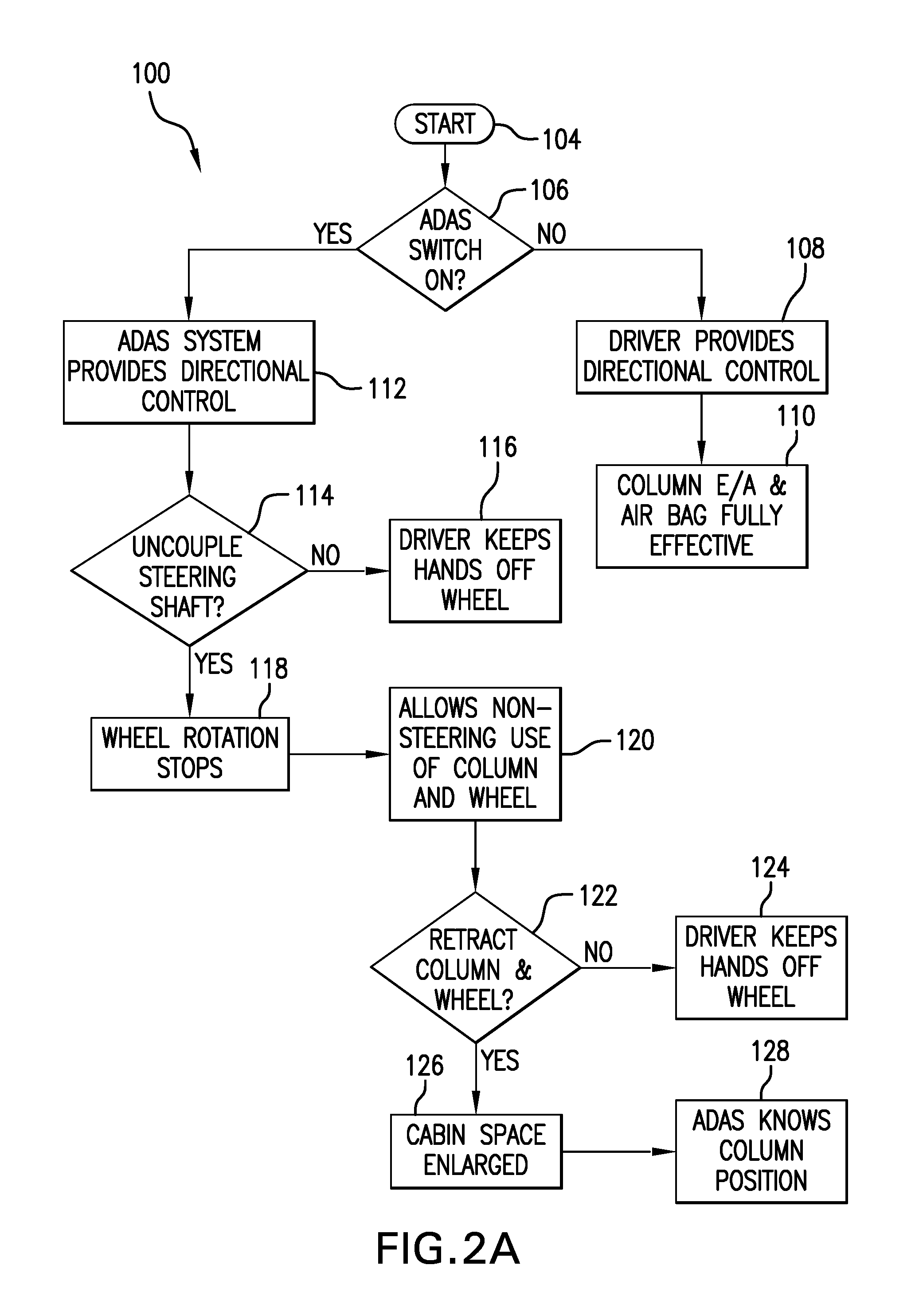
FIGS. 2A and 2B show a flowchart demonstrating an operation of the vehicle and steering column assembly according to one embodiment of the disclosure.
DETAILED DESCRIPTION
A detailed description of one or more embodiments of the disclosed system and method are presented herein by way of exemplification and not limitation with reference to the Figures.
Referring now to the Figures, where embodiments will be described, without limiting same, FIG. 1 schematically illustrates an embodiment of a vehicle 10, such as an autonomous driving assisted steering ("ADAS") equipped vehicle, generally having an instrument panel 12 and a retractable steering column assembly 14. Steering column assembly 14 generally includes a steering column shaft 16 and a steering input device, such as steering wheel 18, coupled thereto.
In the illustrated embodiment, steering column assembly 14 is movable between a retracted position 20, a deployed or driving position 22, and an accessory or utility position 24. In the retracted position 20, portions of assembly 14 such as steering wheel 18 are disposed away from the driver toward or into instrument panel 12, which provides increased space for the driver. In the illustrated embodiment, instrument panel 12 includes one or more receiving compartments or areas 26 to receive some or all of steering column assembly 14. For example, receiving area 26 may be configured to receive steering wheel 18 such that wheel 18 and thus assembly 14 may be stowed within and flush with instrument panel 12. In such an embodiment, the steering column assembly 14 is stowable, however the distance in which the assembly 14 is retracted can be varied. The displacement of the steering column shaft 16 and wheel 18 in retracted position 20 creates additional cabin space for the driver's comfort and convenience to perform non-driving activities including, but not limited to, reading, working, entertaining, eating, texting, etc.
In the driving position 22, steering wheel 18 may be used by a driver to steer the vehicle. In the accessory position 24, portions of assembly 14 such as steering wheel 18 may be used for non-driving activities such as reading, working, or other forms of entertainment. As such, at least a portion of steering wheel 18 is configured to be non-rotatable such that objects like computers or books may be rested thereupon. Further, at least a portion of the steering wheel 18 may be pivoted with respect to the steering column shaft 16 (reducing an angle between the steering column shaft 16 and the portion of the steering wheel 18) to form a work area. For example, a tray table or work surface 28 may be coupled to or integrated with steering wheel 18 to enable such activities. Alternatively, only a rim or hub of the steering wheel is non-rotatable and includes attachments such as hooks to support work surface 28. In other embodiments, an electronic device or the like is integrated into the stationary wheel 18 or work surface 28. The steering wheel 18 may also be moved to bring the work surface 28 closer to the driver as needed in the accessory position 24.
In one embodiment, steering column assembly 14 further includes a steering column adjustment assembly 30, a decoupling assembly 32, a torque interface assembly 34, and one or more sensors 36. Adjustment assembly 30 is configured to move steering column assembly 14 for driver comfort (e.g., telescope or rake adjustment) and to move assembly 14 between the retracted position 20 and the driving position 22. Adjustment assembly 30 may include one or more mechanical/electrical mechanisms such as a motor. Adjustment assembly 30 may also include a retraction mechanism that enables a driver to mechanically, electronically, or manually return steering wheel 18 from the retracted position 20 to the driving position 22.
In the driving position 22, a steering gear 44 links rotation of the steering wheel 18 to turning of the road wheels 46. The steering gear 44 may be mechanically connected to the steering column shaft 16, or alternatively may be electrically connected to the steering column shaft 16, such as in a "steer by wire" system. In one embodiment, decoupling assembly 32 is configured to selectively decouple one or more portions of assembly 14 (e.g., shaft 16) from the vehicle steering gear 44 such that steering wheel 18 is in a non-rotatable mode, removing the ability of the steering wheel 18 to control a direction of road wheels 46 through the steering gear 44. This decoupling assembly 32 may be mechanically or electrically activatable by a clutch, or by steer-by-wire, or counter-rotated by a servo-actuator, for example. Alternatively or additionally, assembly 32 may provide a counter rotation to wheel 18 to counteract any rotation of wheel 18 caused by the autonomous driver assisted steering system such that wheel 18 functions and appears as non-rotatable. The decoupling assembly 32 need not be located along the shaft 16, and may be positioned elsewhere for decoupling the shaft 16 either mechanically and/or electrically from the steering gear 44.
Further, the decoupling assembly 32 allows the steering column shaft 16 and wheel 18 to be displaced forward in the vehicle 10 to the retracted position 20 because the steering wheel 18 is no longer being used by the driver to guide the vehicle 10. The retracting action may accomplished by, for example, long stroke, electrical actuators responding to the driver's intention through a switch and motor controller, or by the driver manually releasing a clamp and pushing the steering wheel 18 and steering column shaft 16 forward to the retracted position 20. In any case, the embodiments described herein make retraction of the steering column shaft 16 and wheel 18 away from the driver possible in order to provide space for non-driving related activities such as working, reading, and game playing.
In the exemplary embodiment, torque interface assembly 34 is configured to detect and monitor driver torque input (rotational and translational) to steering wheel 18, for example, to determine if the driver is in control of the vehicle. Sensors 36 are configured to detect and monitor driver compartment conditions, the driver's condition, the vehicle environment, and/or the vehicle control systems. For example, sensors 36 may: detect objects between the retracted steering wheel and the driver that may cause an unsafe situation for the driver to safely retake control of the vehicle; detect if the driver is not in a position to safely retake control of the vehicle; and/or detect undesirable vehicle dynamics that require the driver to retake control of the vehicle. Whether in the retracted position 20, the deployed/driving position 22, or the accessory/utility position 24, the fore-aft position of the steering column shaft 16 and wheel 18 is known by the ADAS system 98 by one or both of the torque interface assembly 34 and the sensors 36, which may be positioned on the steering column shaft 16 or wheel 18. Sensors may include, but are not limited to switches and potentiometers.
The retracting or stowing process of moving the steering column shaft 16 and wheel 18 from the driving position 22 (or accessory/utility position 24) to the retracted position 20 must eventually be reversed to return steering control of the vehicle 10 to the driver. That is, the driver should be able to reach forward, grip the wheel 18, and be able to relatively quickly bring the wheel 18 to the driving position 22 to resume steering of the vehicle 10. To resume steering of the vehicle 10, the steering shaft 16 is mechanically and/or electrically reconnected to the steering gear 44. Such reconnection may be accomplished by the decoupling assembly 32, such that the decoupling assembly 32 is effectively a steering wheel coupler/de-coupler. When returned to the driving position 22, the steering column 16 and steering wheel 18 are fixed, at least temporarily, such as by the decoupling assembly 32 and/or a deactivatable, reversible lock 38, in that fore-aft position of the driving position 20. When fixed in the driving position 20, the vehicle 10 provides the ability to reduce the driver's kinetic energy, such as may result from a crash, via an energy absorbing mechanism 40 in the steering column shaft 16, the deformation of the steering wheel 18, and the deployment of the driver's air bag 42. In the deployed condition of the air bag 42, the air bag 42 is also capable of absorbing energy.
With reference now to FIGS. 2A and 2B, an embodiment of an operation 100 of the vehicle 10 is shown. Starting with FIG. 2A, a start 104 of the operation may be assessed by a controller 102 of an ADAS system, shown diagrammatically at 98 in FIG. 1. The controller 102 may receive information (signal) from, but not limited to, one or more of the steering column adjustment assembly 30, decoupling assembly 32, torque interface assembly 34, sensors 36, reversible lock 38, as well as any other feature within the vehicle 10 that is communicable with the controller 102. The operation 100 will determine, as demonstrated by block 106, whether an ADAS switch of the ADAS system 98 is on, such as by driver input to initiate the ADAS mode. When the ADAS switch is not on, then, as demonstrated by block 108, a driver provides directional control. As demonstrated by block 110, the energy absorbing mechanism 40 and air bag 42 are rendered operational (the air bag 42 is ready to deploy if required).
When the ADAS switch is on, then, as demonstrated by block 112, the ADAS system 98 provides directional control. The controller 102 further determines, as demonstrated by block 114, if the steering shaft 16 has been decoupled yet, such as by decoupling assembly 32. If not, then as demonstrated by block 116, the driver keeps hands off the steering wheel 18 in order to continue with ADAS control (otherwise, ADAS switch will be switched off due to driver input through steering wheel 18, the steering shaft 16 will remain coupled to steering gear 44, and the driver will provide control). If the steering shaft 16 is decoupled, then as demonstrated by block 118, rotation of wheel 18 is stopped. As demonstrated by block 120, the rotationally-fixed steering wheel 18 allows non-steering use of the column shaft 16 and wheel 18.
At some point during the operation 100, a driver may wish to retract the steering wheel 18. The controller 102 will determine, such as via receipt of a signal from steering column adjustment assembly 30 or any sensors 36 relating to position, as demonstrated by block 122, if the column shaft 16 and wheel 18 are fully retracted during the retracting operation to position 20. If not, then as demonstrated by block 124, the driver will keep hands off the steering wheel 18. However, if the steering column shaft 16 and wheel 18 are retracted in the retracted position 20, then as demonstrated by block 126, cabin space within the vehicle 10 is enlarged and, as demonstrated by block 128, the ADAS system 98 is aware of the position of the column 16, such as via controller 102 and at least one sensor communicable with the controller 102.
With reference now to FIG. 2B, (a continuance of the operation 100 shown in FIG. 2A), non-driving activities are enabled, as demonstrated by block 130, due to the cabin space enlargement (block 126 of FIG. 2A). During the operation 100, the controller 102 will further determine, as demonstrated by block 132, whether or not the driver has gripped the wheel 18. If the driver does not grip the wheel 18, then as demonstrated by block 134, the ADAS system 98 will continue to provide directional control. However, if the driver has gripped the wheel 18, then as demonstrated by block 136, the ADAS system 98 prepares to disengage. As demonstrated by block 138, the column shaft 16 begins to extend. Extension of the column shaft 16 may be done via the driver and/or by automatic extension as a response to driver input. The controller 102 will determine, as demonstrated by block 140, whether or not the column shaft 16 is fully extended. If the column shaft 16 is not fully extended to the driving position 22, then the ADAS system 98 will continue to provide directional control to the vehicle 10, as demonstrated by block 142. However, if the column shaft 16 is fully extended, then, as demonstrated by block 144, the driver provides direction control via the steering wheel 18, and the column energy absorbing mechanism 40 and air bag 42 are rendered operational (with the air bag 42 ready to deploy if required), as demonstrated by block 146. Complete extension of the column shaft 16 may be determined by the controller 102, for example, by actuation of the lock 38 or information from the decoupling assembly 32 or steering column adjustment assembly 30.
Thus, operation 100 ensures that the column energy absorbing mechanism 40 and air bag 42 are operational and activatable, if needed, when the steering column shaft 16 is extended to the driving position 22 and the driver is providing directional control 108 of the vehicle 10.
The use of the terms "a" and "an" and "the" and similar referents in the context of describing the invention (especially in the context of the following claims) are to be construed to cover both the singular and the plural, unless otherwise indicated herein or clearly contradicted by context. Further, it should further be noted that the terms "first," "second," and the like herein do not denote any order, quantity, or importance, but rather are used to distinguish one element from another. The modifier "about" used in connection with a quantity is inclusive of the stated value and has the meaning dictated by the context (e.g., it includes the degree of error associated with measurement of the particular quantity).
While the invention has been described in detail in connection with only a limited number of embodiments, it should be readily understood that the invention is not limited to such disclosed embodiments. Rather, the invention can be modified to incorporate any number of variations, alterations, substitutions or equivalent arrangements not heretofore described, but which are commensurate with the spirit and scope of the invention. Additionally, while various embodiments of the invention have been described, it is to be understood that aspects of the invention may include only some of the described embodiments. Accordingly, the invention is not to be seen as limited by the foregoing description.
* * * * *
D00000
D00001
D00002
D00003
XML
uspto.report is an independent third-party trademark research tool that is not affiliated, endorsed, or sponsored by the United States Patent and Trademark Office (USPTO) or any other governmental organization. The information provided by uspto.report is based on publicly available data at the time of writing and is intended for informational purposes only.
While we strive to provide accurate and up-to-date information, we do not guarantee the accuracy, completeness, reliability, or suitability of the information displayed on this site. The use of this site is at your own risk. Any reliance you place on such information is therefore strictly at your own risk.
All official trademark data, including owner information, should be verified by visiting the official USPTO website at www.uspto.gov. This site is not intended to replace professional legal advice and should not be used as a substitute for consulting with a legal professional who is knowledgeable about trademark law.