Steering Arrangement
Lubischer; Frank P. ; et al.
U.S. patent application number 15/059607 was filed with the patent office on 2016-12-29 for steering arrangement. The applicant listed for this patent is Steering Solutions IP Holding Corporation. Invention is credited to Frank P. Lubischer, Richard K. Riefe.
| Application Number | 20160375926 15/059607 |
| Document ID | / |
| Family ID | 57601852 |
| Filed Date | 2016-12-29 |


| United States Patent Application | 20160375926 |
| Kind Code | A1 |
| Lubischer; Frank P. ; et al. | December 29, 2016 |
STEERING ARRANGEMENT
Abstract
A steering arrangement provided with an autonomous vehicle includes a steering wheel. The steering wheel is selectively coupled to a steering shaft. The steering wheel is selectively switched between a rotatable condition and a non-rotatable condition by an advanced driver assist system. The steering wheel has a steering wheel body defining a receptacle and a convenience assembly that is movable between an open position and a closed position.
| Inventors: | Lubischer; Frank P.; (Commerce Twp., MI) ; Riefe; Richard K.; (Saginaw, MI) | ||||||||||
| Applicant: |
|
||||||||||
|---|---|---|---|---|---|---|---|---|---|---|---|
| Family ID: | 57601852 | ||||||||||
| Appl. No.: | 15/059607 | ||||||||||
| Filed: | March 3, 2016 |
Related U.S. Patent Documents
| Application Number | Filing Date | Patent Number | ||
|---|---|---|---|---|
| 62186078 | Jun 29, 2015 | |||
| Current U.S. Class: | 74/493 |
| Current CPC Class: | B60R 2011/001 20130101; B62D 1/183 20130101; B60R 11/02 20130101; B60R 2011/0094 20130101; B60R 2011/0075 20130101 |
| International Class: | B62D 1/183 20060101 B62D001/183; B60R 7/04 20060101 B60R007/04; B60R 11/02 20060101 B60R011/02; B60R 11/00 20060101 B60R011/00; B62D 1/06 20060101 B62D001/06; B62D 1/10 20060101 B62D001/10 |
Claims
1. A steering arrangement in a selectively autonomous vehicle, comprising: a steering wheel selectively coupled to a steering shaft, the steering wheel having a driver convenience assembly movable between a closed position and an open position; and a controller in communication with the vehicle, the controller programmed to, in response to a request to activate an advanced driver assist system, operatively decouple the steering wheel from the steering shaft and enable the driver convenience assembly to move from the closed position towards the open position.
2. The steering arrangement of claim 1, wherein the controller is further programmed to, in response to the request to activate the advanced driver assist system, inhibit rotation of the steering wheel.
3. The steering arrangement of claim 1, wherein the controller is further programmed to, in response to the request to activate the advanced driver assist system, move the steering wheel from an extended position towards a retracted position.
4. The steering arrangement of claim 1, wherein the driver convenience assembly includes a cover coupled to at least one of a steering wheel body and a rim that extends at least partially about a steering wheel body.
5. The steering arrangement of claim 4 wherein the steering wheel body defines a receptacle that is covered by the cover when in the closed position.
6. The steering arrangement of claim 4, wherein the driver convenience assembly includes a locking mechanism coupled to the steering wheel body, the locking mechanism inhibiting movement of the cover away from the closed position while the advanced driver assist system is deactivated.
7. A steering arrangement provided with an autonomous vehicle, comprising: a steering wheel, selectively coupled to a steering shaft and selectively switched between a rotatable condition and a non-rotatable condition by an advanced driver assist system, the steering wheel having: a steering wheel body defining a receptacle; and a convenience assembly movable between an open position and a closed position.
8. The steering arrangement of claim 7, wherein the steering wheel is movable between an extended position and a retracted position.
9. The steering arrangement of claim 7, wherein the convenience assembly includes a door pivotally connected to the steering wheel body, the door movable between the closed position and the open position to selectively permit access to the receptacle.
10. The steering arrangement of claim 9, wherein the door is enabled to move from the closed position towards the open position in response to the steering wheel being decoupled from the steering shaft and the steering wheel being in the non-rotatable condition.
11. The steering arrangement of claim 9, wherein the door is inhibited from moving away from the closed position while the steering wheel is operatively coupled to the steering shaft and the steering wheel being in the rotatable condition.
12. A steering arrangement, comprising: a steering wheel is provided with an autonomous vehicle, the steering wheel having a driver convenience assembly, the driver convenience assembly is enabled for use in response to activation of an advanced driver assist system and the steering wheel being in a non-rotatable condition.
13. The steering arrangement of claim 12, further comprising an adjustment assembly that translates the steering wheel from an extended position towards a retracted position, in response to a request to activate the advanced driver assist system.
14. The steering arrangement of claim 13, wherein when the steering wheel is in the retracted position the steering wheel is in the non-rotatable condition.
15. The steering arrangement of claim 13, wherein when the steering wheel is in the retracted position the steering wheel is operatively decoupled from a steering shaft.
16. The steering arrangement of claim 12, wherein the driver convenience assembly includes: a panel connected to a steering wheel body, the panel being movable between a closed position and an open position; and an extensible member received within a recess defined by the steering wheel body and connected to the steering wheel body, the extensible member movable between a stowed position and a deployed position.
17. The steering arrangement of claim 16, wherein the panel is enabled to move between the closed position and the open position when the steering wheel is in the non-rotatable condition and the advanced driver assist system is activated.
18. The steering arrangement of claim 16, wherein the extensible member is movable between the stowed position and the deployed position when the panel is in the open position.
19. The steering arrangement of claim 16, wherein the extensible member defines a working surface and a stop surface disposed opposite the working surface.
20. The steering arrangement of claim 19, wherein the stop surface engages a rim of the steering wheel when the extensible member is in the deployed position.
Description
CROSS-REFERENCES TO RELATED APPLICATIONS
[0001] This patent application claims priority to U.S. Provisional Patent Application Ser. No. 62/186,078, filed Jun. 29, 2015, which is incorporated herein by reference in its entirety.
BACKGROUND
[0002] The present disclosure relates to a steering arrangement for a selectively autonomously controlled vehicle.
[0003] Vehicle steering wheels are typically used to steer a vehicle. With advancements in sensors, electronics and computers it may be possible for a vehicle to steer itself with an autonomous driving assisted steering system.
SUMMARY
[0004] According to an embodiment of the present invention, a steering arrangement in a selectively autonomous vehicle is provided. The steering arrangement includes a steering wheel and a controller. The steering wheel is selectively coupled to a steering shaft and has a driver convenience assembly movable between a closed position and an open position. The controller is in communication with an autonomous vehicle. The controller is programmed to, in response to a request to activate an advanced driver assist system, operatively decouple the steering wheel from the steering shaft and enable the driver convenience assembly to move from the closed position towards the open position.
[0005] According to another embodiment of the present invention, a steering arrangement is provided with an autonomous vehicle. The steering arrangement includes a steering wheel that is selectively coupled to a steering shaft. The steering wheel is selectively switched between a rotatable condition and a non-rotatable condition by an advanced driver assist system. The steering wheel has a body defining a receptacle and a convenience assembly movable between an open position and a closed position.
[0006] According to yet another embodiment of the present invention, a steering arrangement is provided. The steering arrangement includes a steering wheel provided in an autonomous vehicle. The steering wheel has a driver convenience assembly. The driver convenience assembly is enabled for use in response to activation of an advanced driver assist system and the steering wheel being in a non-rotatable condition.
BRIEF DESCRIPTION OF THE DRAWINGS
[0007] The subject matter which is regarded as the invention is particularly pointed out and distinctly claimed in the claims at the conclusion of the specification. The foregoing and other features, and advantages of the invention are apparent from the following detailed description taken in conjunction with the accompanying drawings in which:
[0008] FIG. 1 a side view of a vehicle compartment having a steering arrangement in an extended position;
[0009] FIG. 2 is a side view of the vehicle compartment having the steering arrangement in a retracted position;
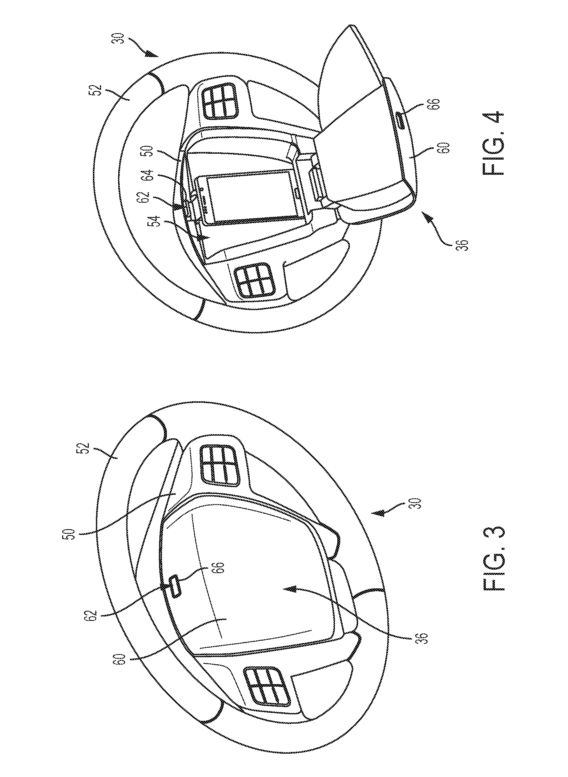
[0010] FIG. 3 is a perspective view of a steering wheel having a first embodiment of a driver convenience assembly in a closed position;
[0011] FIG. 4 is a perspective view of the steering wheel having the first embodiment of the driver convenience assembly in an open position;
[0012] FIG. 5 is a perspective view of the steering wheel having a second embodiment of a driver convenience assembly in a closed position;
[0013] FIG. 6 is a perspective view of the steering wheel having the second embodiment of the driver convenience assembly in an open position; and
[0014] FIG. 7 is a flowchart illustrating a method deploying a driver convenience assembly.
DETAILED DESCRIPTION
[0015] Referring now to the Figures, where the invention will be described with reference to specific embodiments, without limiting same, it is to be understood that the disclosed embodiments are merely illustrative of the invention that may be embodied in various and alternative forms. The figures are not necessarily to scale; some features may be exaggerated or minimized to show details of particular components. Therefore, specific structural and functional details disclosed herein are not to be interpreted as limiting, but merely as a representative basis for teaching one skilled in the art to variously employ the present invention.
[0016] Referring to FIGS. 1 and 2, a side view of a space within an autonomous vehicle, an autonomously driven vehicle, or a selectively autonomous vehicle, such as a vehicle compartment 10, is shown. The autonomous vehicle, the autonomously driven vehicle, or the selectively autonomous vehicle is provided with a steering arrangement 20 and an autonomous driving assisted steering system (ADAS) 22. The ADAS 22 allows the selectively autonomous vehicle to be at least partially autonomously controlled using sensing, steering, and/or braking technology without continuous input from a driver (e.g. steering, accelerating, braking, maneuvering, etc.). A driver of the selectively autonomous vehicle is able to selectively activate or deactivate the ADAS 22 via a switch or other mechanism. A vehicle control system or monitoring system is able to selectively activate or deactivate the ADAS 22 in response to events occurring internal or external to the selectively autonomous vehicle.
[0017] The steering arrangement 20 includes a steering wheel 30, a steering gear 32, an adjustment assembly 34, a driver convenience assembly 36 (FIGS. 3 and 4), and a controller 38. The steering wheel 30 is connected to a steering column 40. The combination of the steering wheel 30 and the steering column 40 are adjustable such that the combination is extendable or retractable along a longitudinal axis 42 that extends through the steering column 40. The combination of the steering wheel 30 and the steering column 40 are tiltable relative to the longitudinal axis 42.
[0018] The steering wheel 30 is directly or indirectly selectively coupled to a steering shaft 44 connected to the steering gear 32. The steering wheel 30 is directly or indirectly selectively coupled to the steering shaft 44 by a coupling mechanism 46. The coupling mechanism 46 may include a disconnect clutch. The steering wheel 30 is coupled to the steering shaft 44 when the disconnect clutch of the coupling mechanism 46 is at least partially engaged and the ADAS 22 is deactivated. The steering wheel 30 is decoupled from the steering shaft 44 when the disconnect clutch of the coupling mechanism 46 is disengaged and the ADAS 22 is activated.
[0019] The rotation of the steering shaft 44 results in rotation or actuation of the steering gear 32 that pivots at least one vehicle wheel to steer or turn the selectively autonomous vehicle. The steering shaft 44 is rotated by the ADAS 22 or a driver input provided to the steering wheel 30.
[0020] In at least one embodiment, the coupling mechanism 46 is configured as a component of a steer by wire system that electrically couples the steering wheel 30 to the steering shaft 44 connected to the steering gear 32. The coupling mechanism 46 includes a device, such as a rotary encoder, that interprets rotation of the steering wheel 30 and applies the information to an actuator that rotates the steering shaft 44 connected to the steering gear 32 that pivots at least one vehicle wheel. The device provides a signal to the actuator when the ADAS 22 is deactivated. The device does not provide a signal or the signal is ignored by the actuator when the ADAS 22 is activated.
[0021] The steering wheel 30 is switchable between a rotatable condition and a non-rotating condition. The steering wheel 30 is in a rotatable condition when the ADAS 22 is deactivated. The driver of the selectively autonomous vehicle is able to provide directional control of the selectively autonomous vehicle through the steering wheel 30 when the ADAS 22 is deactivated. The steering wheel 30 is in a non-rotating condition when the ADAS 22 is activated. The steering wheel 30 is inhibited from rotating in the non-rotating condition. The steering wheel 30 is in the non-rotating condition when the steering wheel 30 is operatively decoupled from the steering shaft 44. In at least one embodiment, when the ADAS 22 is activated, the steering shaft 44 counter rotates such that no rotation of the steering wheel 30 is caused by the performance of steering maneuvers controlled by the ADAS 22. It is to be appreciated that "decoupling" the steering wheel 30 from the steering shaft 44 may be done mechanically, electrically, or a combination thereof.
[0022] The steering wheel 30 and the steering column 40 are movable between an extended position and a retracted position. The extended position corresponds to a position in which a driver of the selectively autonomous vehicle is able to provide steering input via the steering wheel 30, as shown in FIG. 1. The retracted position corresponds to a position in which the driver of the selectively autonomous vehicle is not required to provide steering input via the steering wheel 30, as shown in FIG. 2. The retracted position provides increased space within the vehicle compartment 10 for the driver of the selectively autonomous vehicle to perform non-driving activities.
[0023] The steering wheel 30 is movable between the extended position and the retracted position by the adjustment assembly 34. The adjustment assembly 34 is in communication with the controller 38. The adjustment assembly 34 includes an actuator and an extension member. The actuator is disposed proximate the steering column 40. In at least one embodiment, the actuator is disposed within the selectively autonomous vehicle's instrument panel. The actuator is at least one of an electronic actuator, a hydraulic actuator, a pneumatic actuator, or the like.
[0024] The extension member is operatively coupled to the actuator and at least one of the steering wheel 30 and the steering column 40. The extension member is at least one of a lead screw, a sliding shaft, a telescoping shaft, or the like. The actuator and the extension member are arranged to move the steering wheel 30 and the steering column 40 between the extended position and the retracted position.
[0025] The adjustment assembly 34 is configured to move the steering wheel 30 and the steering column 40 from the retracted position towards the extended position in response to a request to deactivate the ADAS 22. As the steering wheel 30 moves towards the extended position or subsequent to the steering wheel 30 achieving the extended position, the coupling mechanism 46 operatively couples the steering wheel 30 to the steering shaft 44 connected to the steering gear 32.
[0026] The adjustment assembly 34 is configured to move the steering wheel 30 and the steering column 40 from the extended position towards the retracted position in response to a request to activate the ADAS 22. As the steering wheel 30 moves towards the retracted position or prior to the steering wheel 30 moving towards the retracted position, the coupling mechanism 46 operatively decouples the steering wheel 30 from the steering shaft 44 connected to the steering gear 32.
[0027] The selective activation of the ADAS 22 results in the steering wheel 30 becoming operatively decoupled from the steering shaft 44 and the steering gear 32. The steering wheel 30 switches from a rotatable condition to a non-rotatable condition, in response to the operative decoupling of the steering wheel 30 from the steering shaft 44 connected to the steering gear 32. The steering wheel 30 and the steering column 40 moves from the extended position towards the retracted position, in response to the steering wheel 30 being in a non-rotatable condition.
[0028] Referring to FIGS. 3 and 4, the steering wheel 30 includes a steering wheel body 50 and a rim 52 that extends at least partially around the steering wheel body 50. The steering wheel body 50 defines a receptacle or a recess 54. The recess 54 is configured to receive a mobile electronic device, cellular phone, a two-way radio, a tablet computing device, a portable electronic device, a book, a notepad, or the like. It is to be understood that the preceding list of examples is not exhaustive and is merely illustrative of objects or devices that may be inserted into the recess 54.
[0029] The driver convenience assembly 36 is movable between a closed position and an open position. The driver convenience assembly 36 is configured to cover the recess 54 when in the closed position. The driver convenience assembly 36 is configured to permit access to the recess 54 when in the open position.
[0030] The driver convenience assembly 36 is integral to the steering wheel 30 or the steering column 40. The driver convenience assembly 36 includes a cover 60 and a locking mechanism 62. The cover 60 is coupled to at least one of the steering wheel body 50 and the rim 52. The cover 60 is configured as a tray table, a work surface, a platform, a cover having a cup holder, or the like when in the open position. The combination of the cover 60 and the recess 54 defines a storage compartment.
[0031] The locking mechanism 62 is disposed on the steering wheel body 50. The locking mechanism 62 includes a locking element 64. Locking element 64 extends through an opening 66 defined by the cover 60 when the cover is in the closed position. The locking element 64 of the locking mechanism 62 inhibits movement of the cover 60 away from the closed position while the ADAS 22 is deactivated, the steering wheel 30 is in a rotatable condition, and/or the steering wheel 30 is operatively coupled to the steering shaft 44 connected to the steering gear 32.
[0032] The locking element 64 is enabled to be depressed or moved such that the cover 60 is movable from the closed position towards the open position. The locking element 64 of the locking mechanism 62 is enabled to be moved while the ADAS 22 is activated, the steering wheel 30 is in a non-rotatable condition, and the steering wheel 30 is operatively decoupled from the steering shaft 44 connected to the steering gear 32.
[0033] Referring to FIGS. 5 and 6, a second embodiment of a driver convenience assembly 70 is shown. The driver convenience assembly 70 includes a door 72 pivotally connected to the steering wheel body 50 and a latching mechanism 74. The door 72 is configured to cover or conceal the recess 54 or secure items that are placed within the recess 54 of the steering wheel body 50. The door 72 is movable between a closed position that inhibits access to the recess 54 and an open position that permits access to the recess 54.
[0034] The door 72 includes an extension portion 80 that is disposed opposite the latching mechanism 74. The extension portion 80 is received within a receiving portion 82 disposed within the recess 54. The extension portion 80 and the receiving portion 82 have a tab and slot configuration, respectively. The extension portion 80 and the receiving portion 82 form a hinge that connects the door 72 to the steering wheel body 50.
[0035] The latching mechanism 74 inhibits the door 72 from moving away from the closed position. The latching mechanism 74 is laterally centered across the steering wheel body 50. The latching mechanism 74 is disposed proximate an edge of the recess 54. The latching mechanism 74 includes a tab or finger 90 that extends from an end of the door 72. The finger 90 is releasably received within a slot 92. The slot 92 is defined by a sidewall of the recess 54 or defined by an interior wall of the recess 54. In at least one embodiment, the latching mechanism 74 includes a bayonet that extends from an end of the door 72 that is received within a clasp disposed within the recess 54.
[0036] The door 72 is enabled to move from the closed position towards the open position in response to the steering wheel 30 being decoupled from the steering shaft 44 connected to the steering gear 32, the steering wheel 30 being in a non-rotatable condition, and the ADAS 22 being activated. The door 72 is inhibited from moving away from the closed position in response to the steering wheel 30 being coupled to the steering shaft 44 connected to the steering gear 32, the steering wheel 30 being in a rotatable condition, and/or the ADAS 22 being deactivated.
[0037] In at least one embodiment, the driver convenience assembly 70 includes a second door 100 and a second latching mechanism 102. The second door 100 and the second latching mechanism 102 have a substantially similar, but mirrored configuration as the door 72 and the latching mechanism 74. The second door 100 is spaced apart from the door 72.
[0038] The controller 38 may be provided as part of the ADAS 22. In at least one embodiment, the controller 38 is provided as a separate component from the ADAS 22 and is in communication with the autonomous vehicle, the autonomously driven vehicle, or the selectively autonomous vehicle. The controller 38 is configured to receive information or signals from the ADAS 22, a sensor associated with the ADAS 22, the steering wheel 30, the adjustment assembly 34, the driver convenience assembly (36, 70, 110), the steering shaft 44, and the coupling mechanism 46.
[0039] The controller 38 interprets the various signals provided by the steering arrangement 20 and the ADAS 22 to determine whether to activate or deactivate the ADAS 22. The controller 38 issues commands to and receive signals from the steering arrangement 20, the ADAS 22, the steering wheel 30, the adjustment assembly 34, the driver convenience assembly (36, 70, 110), the steering shaft 44, and the coupling mechanism 46. These commands and signals may result in the steering wheel 30 being operatively coupled or operatively decoupled from the steering shaft 44 connected to the steering gear 32, and the steering wheel 30 and the steering column 40 being in a retracted position or a deployed position, the steering wheel 30 being a rotating condition or a non-rotating condition.
[0040] The controller 38 includes a microprocessor or central processing unit (CPU) in communication with various types of computer readable storage devices or media. Computer readable storage devices or media may include volatile and nonvolatile storage in read-only memory (ROM), random-access memory (RAM), and keep-alive memory (KAM), for example. KAM is a persistent or non-volatile memory that may be used to store various operating variables while the CPU is powered down. Computer-readable storage devices or media may be implemented using any of a number of known memory devices such as PROMs (programmable read-only memory), EPROMs (electrically PROM), EEPROMs (electrically erasable PROM), flash memory, or any other electric, magnetic, optical, or combination memory devices capable of storing data, some of which represent executable instructions, used by the controller 38 in controlling the steering arrangement 20 and the ADAS 22.
[0041] Referring to FIGS. 7, a flowchart illustrating a method of deploying a driver convenience assembly in a selectively autonomous vehicle is shown. As will be appreciated by one of ordinary skill in the art, the flowchart represents control logic that may be implemented or affected in hardware, software, or a combination of hardware and software. The various functions may be affected by a programmed microprocessor provided with the controller 38 or provided separately from the controller 38. The control logic may be implemented using any of a number of known programming and processing techniques or strategies and is not limited to the order or sequence illustrated. For instance, interrupt or event driven processing may be employed in real-time control applications rather than a purely sequential strategy is illustrated. Likewise, parallel processing, multitasking, or multi-threaded systems and methods may be used.
[0042] The method may be executed by the controller 38 and may be implemented as a closed loop control system. For brevity, the method will be described in the context of a single method iteration below. The method assesses the operating state of the selectively autonomous vehicle, which may include assessing whether the selectively autonomous vehicle is functional, the operational state of the ADAS 22, the position of the steering wheel 30, the rotatable or non-rotatable condition of the steering wheel 30, or the enablement of the driver convenience assembly 36, 70.
[0043] At block 200, the method assesses whether the ADAS 22 is activated. If the ADAS 22 is not activated, the method continues to block 202. At block 202, the driver of the selectively autonomous vehicle provides directional control of the selectively autonomous vehicle. The driver of the selectively autonomous vehicle provides steering or other inputs via the steering wheel 30 and the method may end. Should the ADAS 22 be activated, the method continues to block 204. At block 204, the ADAS 22 provides directional control to the selectively autonomous vehicle.
[0044] At block 206, the method assesses whether the steering wheel 30 is decoupled or uncoupled from at least one of the steering gear 32 and the steering shaft 44 or the steering shaft 44 is decoupled or uncoupled from the steering gear 32. At block 208, if the driver of the selectively autonomous vehicle keeps their hands on the steering wheel 30, the steering wheel 30 may not be decoupled or uncoupled from at least one of the steering gear 32 and the steering shaft 44, the method may end.
[0045] Should the steering wheel 30 be virtually or literally uncoupled from at least one of the steering gear 32 and a steering shaft 44 or the steering shaft 44 be uncoupled from the steering gear 32, the method continues to block 210. At block 210, the rotation of the steering wheel 30 stops. The steering wheel 30 changes from a rotatable condition to a non-rotatable condition, where the steering wheel 30 is not used to provide directional control of the selectively autonomous vehicle or is counter-rotated by a servo actuator. At block 212, the method permits a non-steering use of the steering wheel 30, in response to the steering wheel 30 being in a non-rotatable condition.
[0046] At block 214, the method determines whether the steering wheel is in an extended position or a retracted position. At block 216, if the driver of the selectively autonomous vehicle keeps their hands on the steering wheel 30, the steering wheel 30 may not be moved from the extended position towards the retracted position and the method may end. Should the driver of the selectively autonomous vehicle not have their hands on the steering wheel, the steering wheel 30 is moved from the extended position towards the retracted position to enlarge cabin space within the vehicle compartment 10 at block 218. The steering wheel 30 and the steering column 40 are displaced forward within the vehicle compartment 10 to enlarge cabin space.
[0047] At block 220, the method determines whether to deploy the driver convenience assembly. If at least one of the steering wheel 30 being in the retracted position, the steering wheel 30 being in a non-rotatable condition, and a driver of the selectively autonomous vehicle does not have their hands on the steering wheel 30 is not met, the method continues to block 222. At block 222, the method permits non-work activities that do not utilize the driver convenience assembly and the method may end. Should at least one of the steering wheel 30 being in the retracted position, the steering wheel 30 being in a non-rotatable condition, and a driver of the selectively autonomous vehicle does not have their hands on the steering wheel 30 is met, the method continues to block 224. At block 224, the method permits or enables a work surface of the driver convenience assembly to be made available for use by the driver of the selectively autonomous vehicle.
[0048] While the invention has been described in detail in connection with only a limited number of embodiments, it should be readily understood that the invention is not limited to such disclosed embodiments. Rather, the invention can be modified to incorporate any number of variations, alterations, substitutions or equivalent arrangements not heretofore described, but which are commensurate with the spirit and scope of the invention. Additionally, while various embodiments of the invention have been described, it is to be understood that aspects of the invention may include only some of the described embodiments. Accordingly, the invention is not to be seen as limited by the foregoing description.
* * * * *
D00000
D00001
D00002
D00003
D00004
XML
uspto.report is an independent third-party trademark research tool that is not affiliated, endorsed, or sponsored by the United States Patent and Trademark Office (USPTO) or any other governmental organization. The information provided by uspto.report is based on publicly available data at the time of writing and is intended for informational purposes only.
While we strive to provide accurate and up-to-date information, we do not guarantee the accuracy, completeness, reliability, or suitability of the information displayed on this site. The use of this site is at your own risk. Any reliance you place on such information is therefore strictly at your own risk.
All official trademark data, including owner information, should be verified by visiting the official USPTO website at www.uspto.gov. This site is not intended to replace professional legal advice and should not be used as a substitute for consulting with a legal professional who is knowledgeable about trademark law.