Retractable Steering Column With Rake Limiter
Rouleau; James E. ; et al.
U.S. patent application number 15/193692 was filed with the patent office on 2016-12-29 for retractable steering column with rake limiter. The applicant listed for this patent is STEERING SOLUTIONS IP HOLDING CORPORATION. Invention is credited to Shawn A. Haring, Todd M. King, James E. Rouleau, Michael Srda.
| Application Number | 20160375929 15/193692 |
| Document ID | / |
| Family ID | 57600880 |
| Filed Date | 2016-12-29 |

| United States Patent Application | 20160375929 |
| Kind Code | A1 |
| Rouleau; James E. ; et al. | December 29, 2016 |
RETRACTABLE STEERING COLUMN WITH RAKE LIMITER
Abstract
A steering column assembly includes an outer jacket, an inner jacket, a pin, and a bracket. The inner jacket is configured to telescopically slide with respect to the outer jacket along a telescopic axis. The pin is engaged to and projects radially outward from one of the inner and outer jackets. The bracket is pivotally engaged to the other of the inner and outer jackets, and includes first and second surfaces that extend substantially axially and are generally opposed to one-another for selective contact with the pin to limit a pivoting range as a function of telescopic position.
| Inventors: | Rouleau; James E.; (Burt, MI) ; Haring; Shawn A.; (Swartz Creek, MI) ; Srda; Michael; (Clio, MI) ; King; Todd M.; (Saginaw, MI) | ||||||||||
| Applicant: |
|
||||||||||
|---|---|---|---|---|---|---|---|---|---|---|---|
| Family ID: | 57600880 | ||||||||||
| Appl. No.: | 15/193692 | ||||||||||
| Filed: | June 27, 2016 |
Related U.S. Patent Documents
| Application Number | Filing Date | Patent Number | ||
|---|---|---|---|---|
| 62186002 | Jun 29, 2015 | |||
| Current U.S. Class: | 74/493 |
| Current CPC Class: | B62D 1/181 20130101; B62D 1/187 20130101 |
| International Class: | B62D 1/187 20060101 B62D001/187; B62D 1/184 20060101 B62D001/184; B62D 1/185 20060101 B62D001/185 |
Claims
1. A steering column assembly comprising: a support structure including first and second surfaces that are substantially opposed to one-another; a first jacket pivotally engaged to the support structure about a pivot axis; a second jacket configured to telescopically slide with respect to the first jacket along a telescopic axis; and a member engaged to and projecting radially outward from the second jacket with respect to the telescopic axis, and wherein the first and second surfaces extend substantially axially with respect to the telescopic axis and are configured for selective contact with the member to limit a pivoting range of the first jacket as a function of telescopic position of the second jacket.
2. The steering column assembly set forth in claim 1, wherein the second jacket is disposed at least in-part radially inward of the first jacket.
3. The steering column assembly set forth in claim 1, wherein the support structure is stationary.
4. The steering column assembly set forth in claim 3, wherein the support structure is a rake bracket.
5. The steering column assembly set forth in claim 1, wherein the member is a pin extending along a centerline that is substantially normal to the telescopic axis.
6. The steering column assembly set forth in claim 5, wherein the pivot axis is substantially normal to the telescopic axis.
7. The steering column assembly set forth in claim 6, wherein the centerline is substantially parallel to the pivot axis.
8. The steering column assembly set forth in claim 1, wherein the member is engaged to the second jacket and extends through an opening in the first jacket.
9. The steering column assembly set forth in claim 8, wherein the opening is axially elongated with respect to the telescopic axis and is defined in-part by forward and rearward stops of the first jacket for contact with the member thereby limiting a telescoping range.
10. The steering column assembly set forth in claim 1, wherein the first and second surfaces converge toward one-another in a telescoping direction along the telescopic axis.
11. The steering column assembly set forth in claim 9, wherein the first and second surfaces converge toward one-another in a telescoping direction along the telescopic axis.
12. The steering column assembly set forth in claim 11, wherein the member extends along a centerline that is substantially parallel to the pivot axis and normal to the telescopic axis.
13. The steering column assembly set forth in claim 12, wherein the first and second surfaces define at least in-part a cavity in the structure for receipt of the member.
14. The steering column assembly set forth in claim 13, wherein the cavity has a forward portion defined by opposing first segments of the respective first and second surface that extend substantially parallel to the telescopic axis.
15. The steering column assembly set forth in claim 14, wherein the cavity has a second portion disposed rearward of the forward portion and defined by opposing second segments of the respective first and second surfaces that converge toward one another as the second segments extend toward the respective first segments.
16. The steering column assembly set forth in claim 15, wherein the forward portion is defined in part by a forward stop carried by the support structure and spanning between the opposing first segments.
17. A steering column assembly comprising: an outer column jacket; an inner column jacket configured to telescopically slide with respect to the outer column jacket along a telescopic axis; a pin engaged to and projecting radially outward from one of the inner and outer jackets; and a bracket pivotally engaged to the other of the inner and outer jackets, the bracket including first and second surfaces that extend substantially axially and are generally opposed to one-another for selective contact with the pin to limit a rake tilting range of the outer jacket as a function of telescopic position.
18. The steering column assembly set forth in claim 17, wherein the pin is engaged to the inner jacket and extends through an axially extending slot in the outer jacket and the outer jacket is pivotally engaged to the bracket.
19. The steering column assembly set forth in claim 18, wherein the slot is defined in part by forward and rearward stops for contact with the pin and configured to limit a telescoping range.
20. A rake limiter for an extendable steering column assembly having a first jacket pivotally engaged to a support structure about a pivot axis and a second jacket configured to telescopically slide with respect to the first jacket along a telescopic axis disposed normal to the pivot axis, the rake limiter comprising: a member engaged to and projecting radially outward from the second jacket with respect to the telescopic axis; and first and second surfaces carried by the support structure and disposed substantially in opposition to one-another, and defining at least in-part a contoured cavity for receipt of the member, and wherein the first and second surfaces are constructed and arranged to contact the member to limit a rake tilting range of the first jacket as a function of telescopic position of the second jacket.
Description
CROSS-REFERENCE TO RELATED APPLICATION
[0001] This patent application claims priority to U.S. Provisional Patent Application Ser. No. 62/186,002, filed Jun. 29, 2015, which is incorporated herein by reference in its entirety.
BACKGROUND OF THE INVENTION
[0002] The present disclosure relates to steering column assemblies, and more particularly, to assemblies with mutually dependent rake and telescopic positions.
[0003] Steering column assemblies for automobiles are known to include various adjustment devices that permit an operator to selectively position and secure the steering column in any one of a variety of positions. Such adjustment devices may include a rake device that facilitates tilting of the steering column and a telescopic device that facilitates the length of the column which generally dictates how close a steering wheel is positioned to the operator (i.e., extended position) and/or how close to the instrument cluster of the automobile (i.e., retracted position). Unfortunately, the extent of a retracted position may be limited by the full range of the rake positions in order to prevent the steering wheel from contacting surrounding components during adjustment.
[0004] Accordingly, it is desirable to provide a mechanism that limits the range of rake positions with such limits dependent upon a particular telescopic position.
SUMMARY OF THE INVENTION
[0005] In one exemplary and non-limiting embodiment of the present disclosure, a steering column assembly includes a support structure, a first jacket, a second jacket and a member. The support structure includes first and second surfaces that are substantially opposed to one-another. The first jacket is pivotally engaged to the support structure about a pivot axis. The second jacket is configured to telescopically slide with respect to the first jacket along a telescopic axis. The member is engaged to and projects radially outward from the second jacket with respect to the telescopic axis. The first and second surfaces extend substantially axially with respect to the telescopic axis and are configured for selective contact with the member to limit a pivoting range of the first jacket as a function of telescopic position of the second jacket.
[0006] In another exemplary embodiment, a steering column assembly includes an outer jacket, an inner jacket, a pin, and a bracket. The inner jacket is configured to telescopically slide with respect to the outer jacket along a telescopic axis. The pin is engaged to and projects radially outward from one of the inner and outer jackets. The bracket is pivotally engaged to the other of the inner and outer jackets, and includes first and second surfaces that extend substantially axially and are generally opposed to one-another for selective contact with the pin to limit a pivoting range as a function of telescopic position.
[0007] These and other advantages and features will become more apparent from the following description taken in conjunction with the drawings.
BRIEF DESCRIPTION OF THE DRAWINGS
[0008] The subject matter which is regarded as the invention is particularly pointed out and distinctly claimed in the claims at the conclusion of the specification. The foregoing and other features, and advantages of the invention are apparent from the following detailed description taken in conjunction with the accompanying drawings in which:
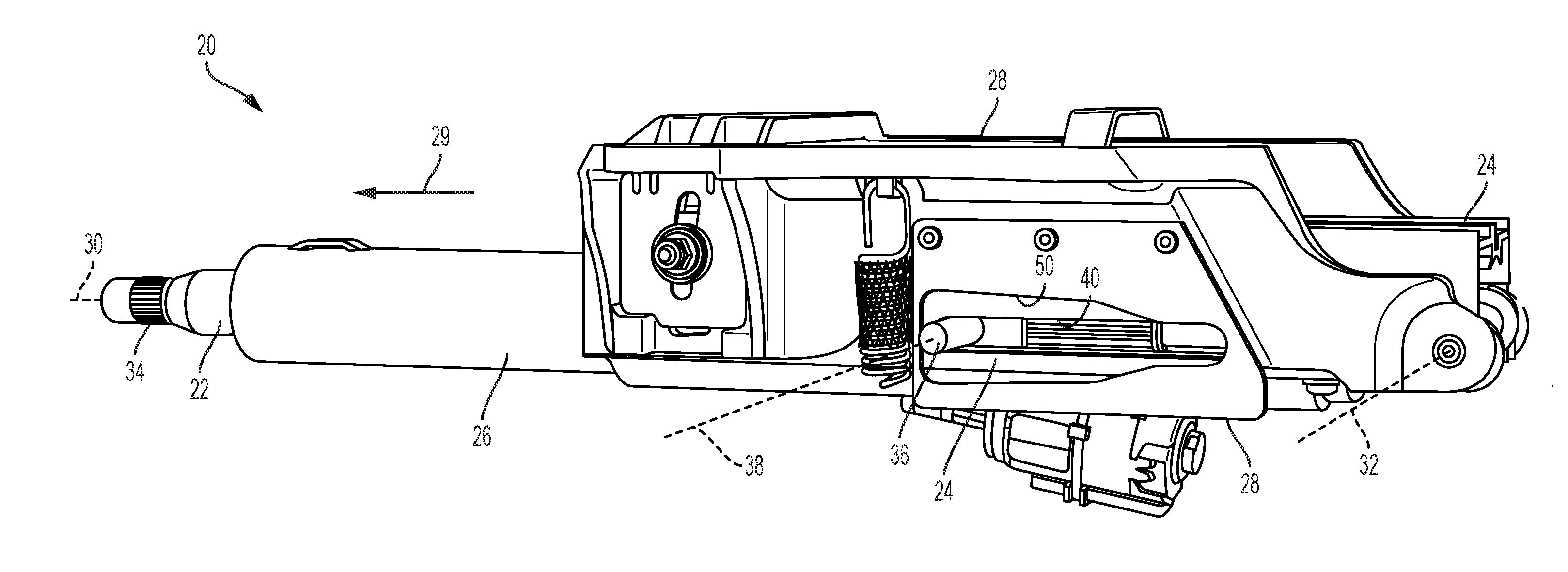
[0009] FIG. 1 is a side view of a steering column assembly in accordance with an exemplary embodiment of the present disclosure;
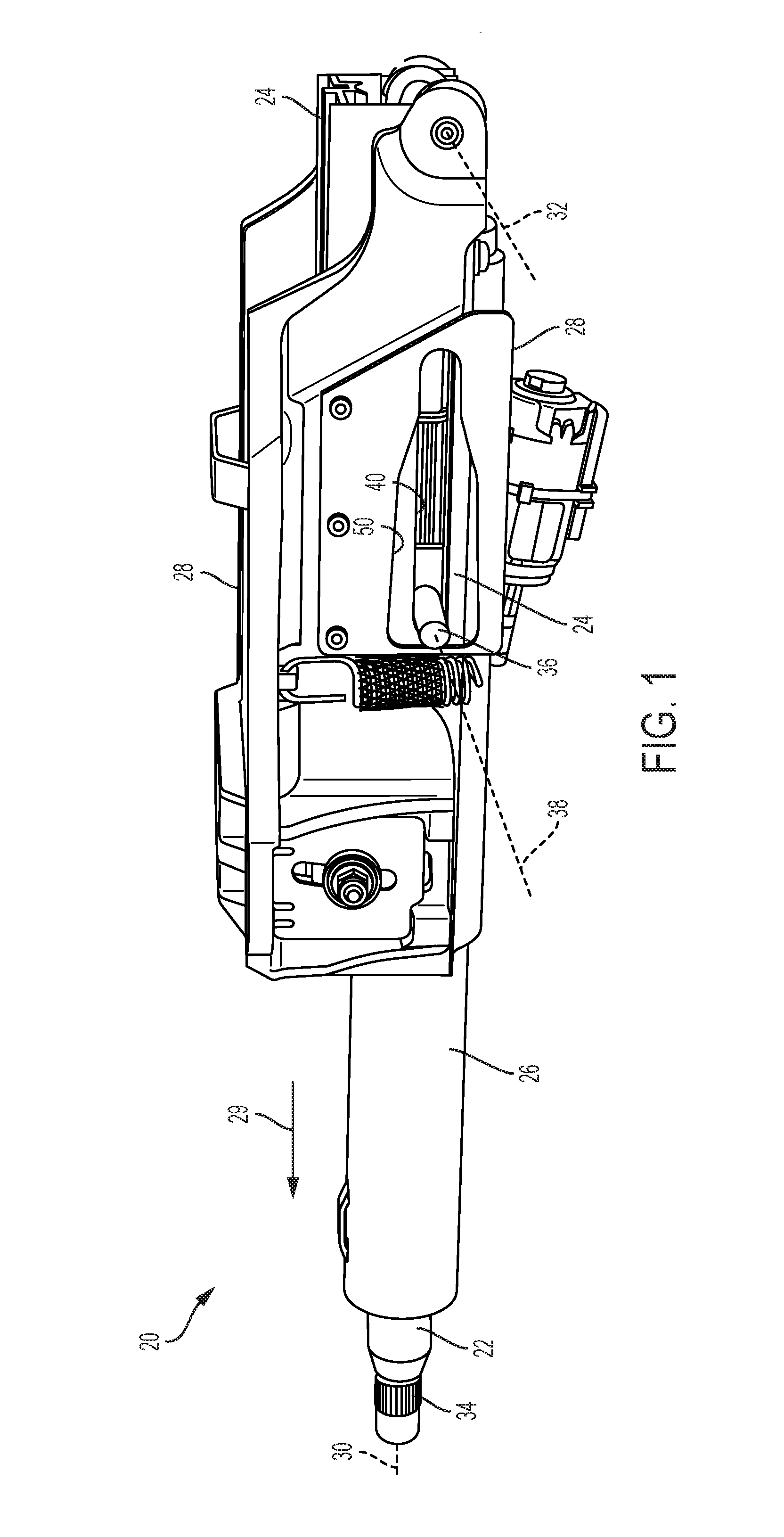
[0010] FIG. 2 is a perspective rear view of the steering column assembly;
[0011] FIG. 3 is a bottom view of the steering column assembly;
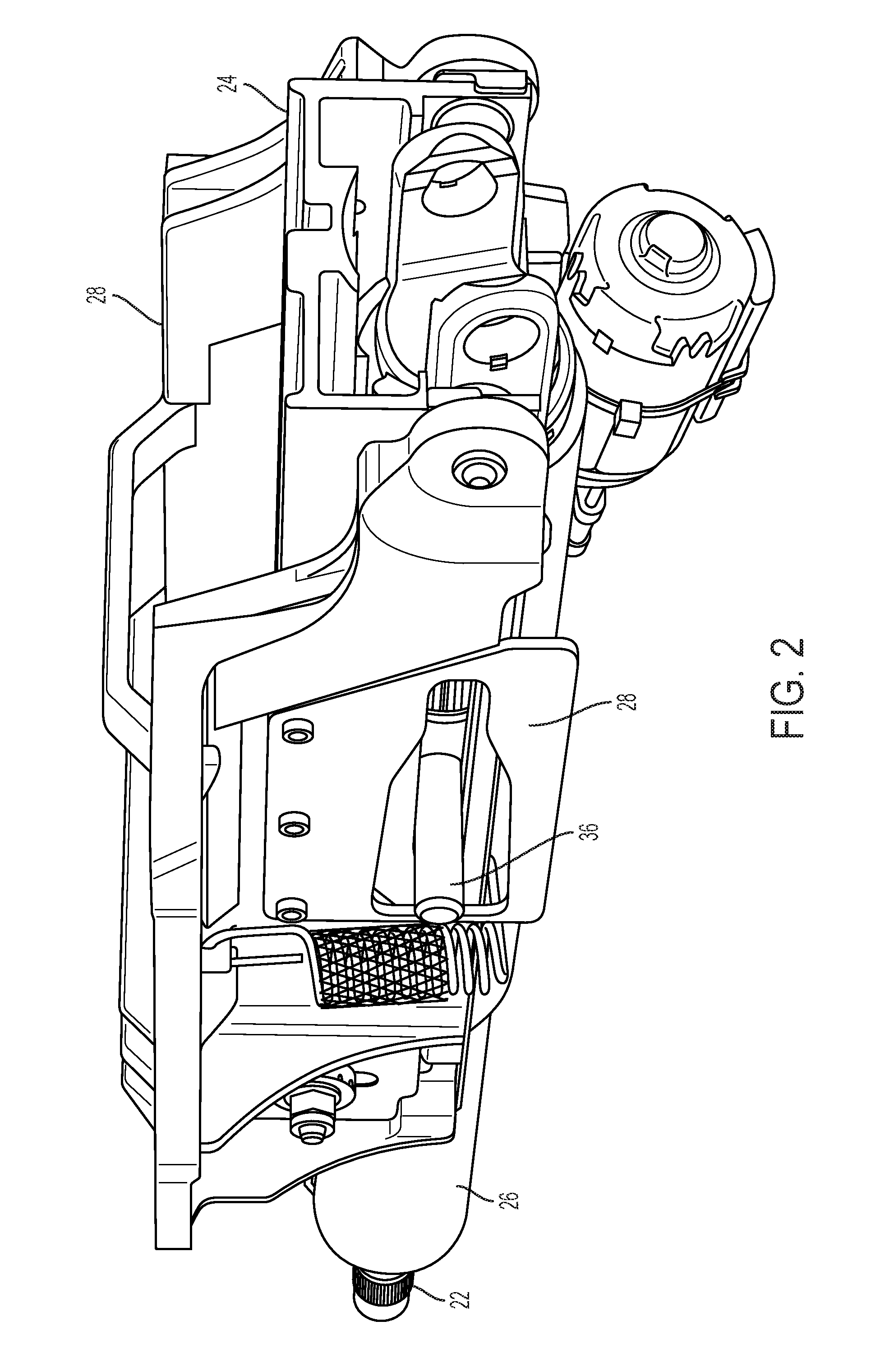
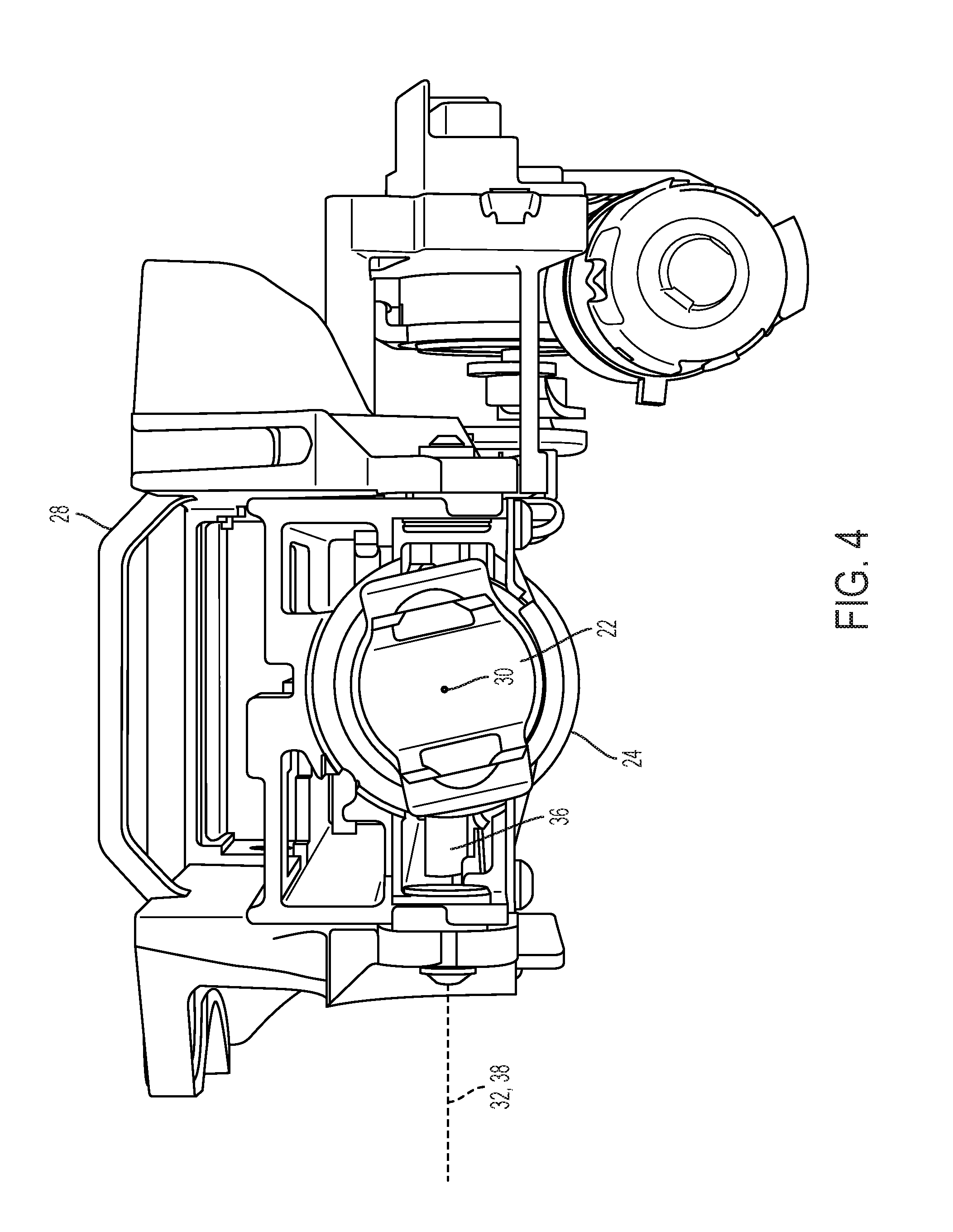
[0012] FIG. 4 is rear view of the steering column assembly;
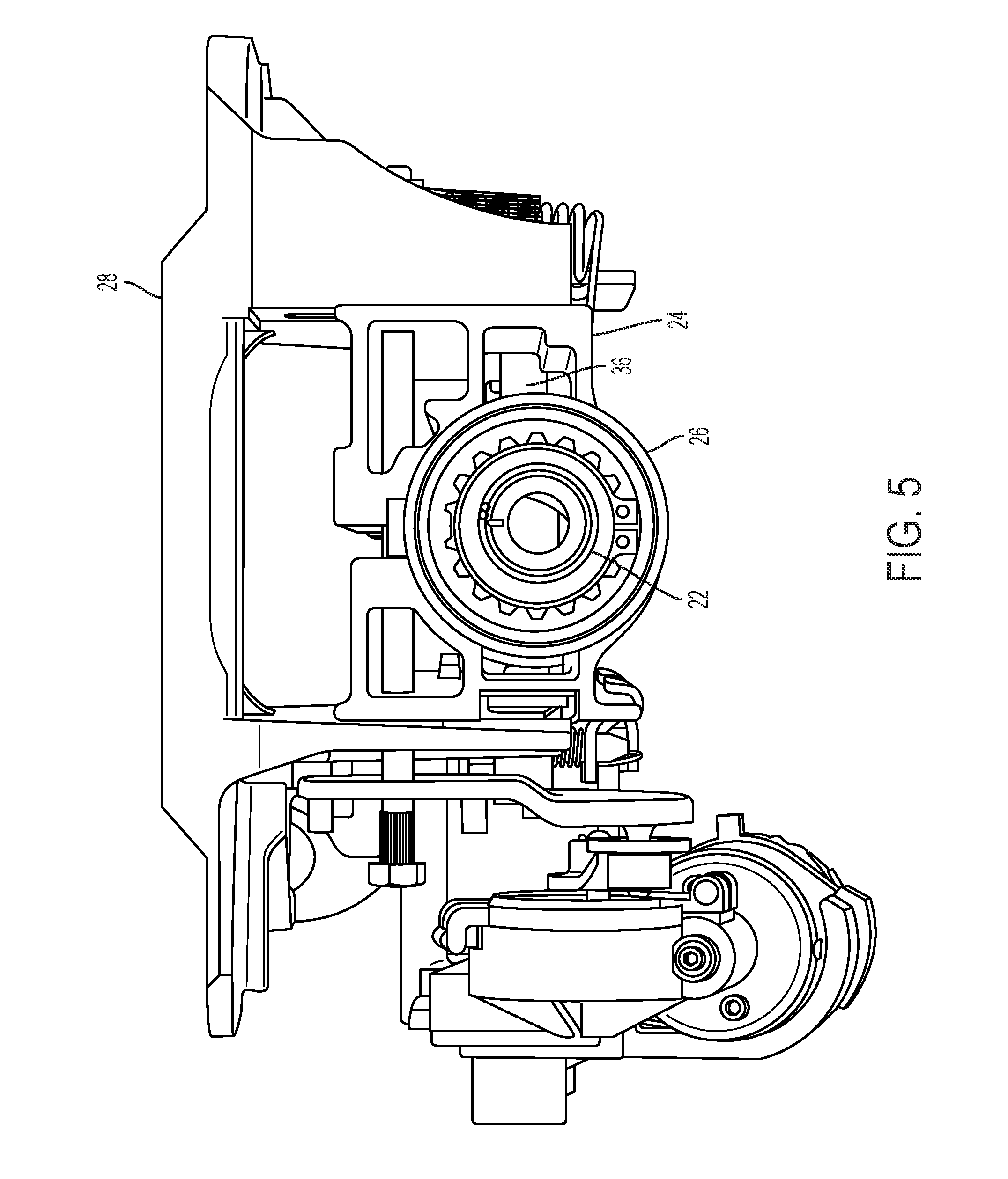
[0013] FIG. 5 is a front view of the steering column assembly;
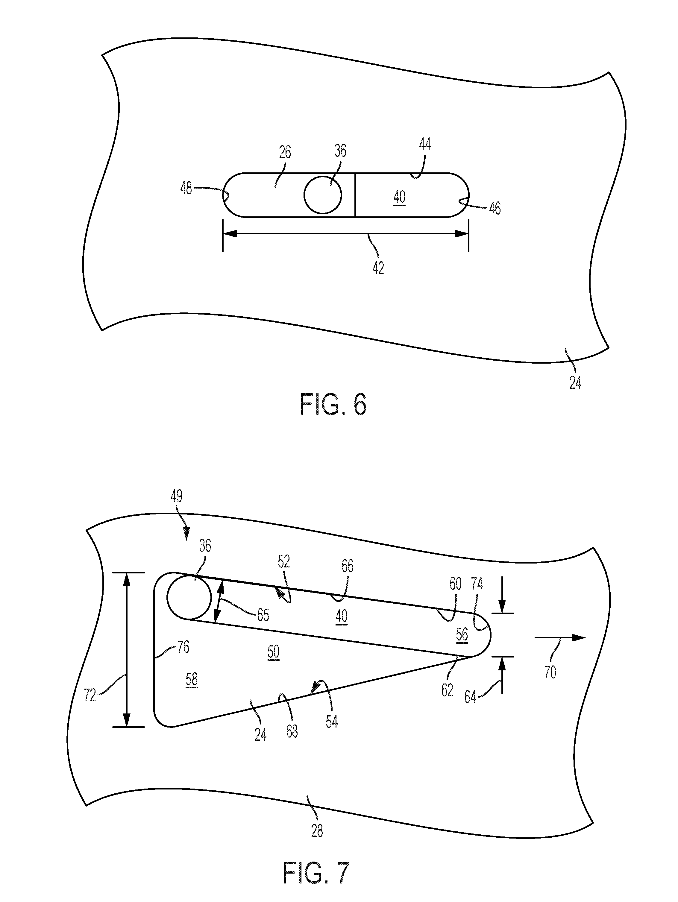
[0014] FIG. 6 is a partial plan view of a lower column jacket and pin of the steering column assembly; and
[0015] FIG. 7 is a partial plan view of a bracket and the pin of the steering column assembly.
DETAILED DESCRIPTION
[0016] Referring now to the Figures, where the invention will be described with reference to specific embodiments, without limiting same, a steering column assembly 20 of the present disclosure is capable of selective adjustment both telescopically and tilt-wise (i.e., rake). The assembly 20 is configured such that the full range of angular rake motion is dependent upon the specific telescopic position.
[0017] Referring to FIGS. 1 through 5, the steering column assembly 20 may include a steering shaft 22 mounted for rotation, first and second column jackets 24, 26, and a support structure 28. The support structure 28 may be a rake bracket that may be rigidly attached to a dash structure and/or may be integral to the dash structure or other structure of a vehicle chassis. The first column jacket 24 may be a forward column jacket (i.e., forward and away from a vehicle driver), and may include a forward end portion pivotally engaged to the support structure 28. The second column jacket 26 may be a rearward column jacket (at least in-part rearward of the first column jacket 24 and forward of the vehicle driver), and may be telescopically connected to the first column jacket 24 thereby projecting in a rearward direction (see arrow 29). The steering shaft 22 may extend along and through the first and second column jackets 24, 26, and may include a plurality of splines 34 at a distal end for engagement to a hand steering wheel (not shown).
[0018] The first column jacket 24 may pivot about a pivot axis 32, and may be further constructed and arranged to pivot between a multitude of rake positions that may be selected by the vehicle driver. Similarly, the second column jacket 26 may be constructed and arranged to slide with respect to the first column jacket 24 along a telescopic axis 30 and between a multitude of telescopic positions (i.e., extended and retracted states) that may be selected by the vehicle driver. It is further contemplated and understood that the first column jacket 24 may be generally positioned lower than the second column jacket 26, and the second column jacket 26 may be at least in-part disposed radially inward from the first column jacket 24 with respect to telescopic axis 30.
[0019] The steering column assembly 20 may further include a member 36 that may be rigidly engaged to the second column jacket 26, and may project substantially radially outward from the jacket 26 with respect to telescopic axis 30 and along a centerline 38. The centerline 38 may be substantially parallel to the pivot axis 32 and substantially normal to the telescopic axis 30. The member 36 may project through a slot 40 in the first column jacket 24 that extends substantially axially with respect to the telescopic axis 30. The member 36 may include any variety of shapes, and may be a pin that may be substantially cylindrical.
[0020] Referring to FIGS. 6 and 7, the slot 40 may have an axial length (see arrow 42) that is about equivalent to or greater than the maximum telescoping travel of the second column jacket 26 with respect to the first column jacket 24. The slot 40 may generally be defined by an edge 44 carried by the first column jacket 24. The edge 44 may be continuous, and may include a forward stop portion 46 and a rearward stop portion 48 orientated to limit the telescoping travel of the second column jacket 26 along telescopic axis 30.
[0021] In operation and when the assembly 20 is in a fully extended position (i.e., telescopically), the member 36 may be in contact with the rearward stop portion 48, and when the assembly 20 is in a fully retracted position, the member 36 may be in contact with the forward stop portion 46. It is further contemplated and understood that the assembly 20 may include alternative telescopic indexes and/or stops that may not be carried by the edge 44. For example, telescopic stops may be carried between the jackets 24, 26 at other locations and not being associated with the member 36 as part of the indexing feature. It is further understood that the slot 40 may be any clearance or opening that permits movement of the member 36 in an axial direction with respect to the telescopic axis 30 as the jackets 24, 26 move between extended and retracted positions.
[0022] The steering column assembly 20 may further include a rake limiter 49 that may include the member 36 and a contoured cavity 50 in the support structure 28 for receipt of the member 36. The member 36 extends through the slot 40 in the first column jacket 24 and into the contoured cavity 50 of the rake limiter 49. The cavity 50 is generally contoured to limit the rake travel as a function of telescopic position along axis 30. The contoured cavity 50 includes boundaries defined by, at least in-part, opposing first and second surfaces 52, 54 (see FIG. 7) carried by the support structure 28. The surfaces 52, 54 may substantially oppose one-another with the first surface 52 facing substantially downward and the second surface 54 facing substantially upward. In operation of the rake limiter 49, the member 36 may contact the first surface 52 when the steering shaft 22, along with the column jackets 24, 24 is pivotally raised to a maximum upper rake position (i.e., as illustrated in FIG. 7). Similarly, the member 36 may contact the second surface 54 when the steering shaft 22 is lowered to a maximum lower rake position (not illustrated).
[0023] The contoured cavity 50 may further include a forward portion 56 and a rearward portion 58. The forward portion 56 may include boundaries defined by opposing first segments 60, 62 of the respective first and second surfaces 52, 54. The first segments 60, 62 may be spaced from one-another by a distance (see arrow 64) that generally designates a minimum angular rake range of travel that may be about zero rake travel. That is, the distance 64 may be about equal to or slightly greater than a width (see arrow 65) of the member 36 that is in the forward portion 56.
[0024] The rearward portion 58 of the contoured cavity 50 may include boundaries defined by opposing second segments 66, 68 of the respective first and second surfaces 52, 54. The second segments 66, 68 may generally converge upon one another as they extend in a forward direction 70 to meet the respective first segments 60, 62. In operation of the assembly 20, and when the column jackets 24, 26 are about fully extended telescopically, a distance (see arrow 72) between the second segments 66, 68 may be at a maximum distance designating a maximum angular rake tilting range.
[0025] The contoured cavity 50 may be further defined by a forward surface 74 that generally faces rearward and connects forward ends of the first segments 60, 62, and a rearward surface 76 that generally faces forward and connects rearward ends of the second segments 66, 68. The forward and rearward surfaces 74, 76 may generally be stops configured to contact the member 36 instead of the stops 46, 48 previously described.
[0026] In operation, an operator of a vehicle may select a fully extended position of the steering column assembly 20. While the second column jacket 26 is moving rearward along the telescopic axis 30, from a retracted state and toward a fully extended state, the member 36 moves away from the forward stop 46 and toward the rearward stop 48. When the second column jacket 26 is not generally in the fully retracted state, the assembly 20 may be tilted or raked in an upward and/or downward pivotal direction and until the member contacts the respective second segments 66, 68.
[0027] When the steering column assembly 20 may also be placed in a fully retracted position. In such a position, the contoured cavity 50 (i.e., defined by surfaces 52, 54) may be contoured (e.g., surfaces 52, 54 may converge), such that the steering wheel (not shown) or other moving components is prevented from contacting surrounding stationary components (e.g., eyebrow of an instrument cluster). To prevent such contact, the rake tilting range may be less than the tilting range when the steering column assembly 20 is in the fully extended position. It is further contemplated and understood that when the assembly 20 is in or near the fully retracted position, the rake tilting range may be generally close to zero (i.e., no tilt adjustment capability) thus the rake may be a nominal position.
[0028] While the invention has been described in detail in connection with only a limited number of embodiments, it should be readily understood that the invention is not limited to such disclosed embodiments. Rather, the invention can be modified to incorporate any number of variations, alterations, substitutions or equivalent arrangements not heretofore described, but which are commensurate with the spirit and scope of the invention. Additionally, while various embodiments of the invention have been described, it is to be understood that aspects of the invention may include only some of the described embodiments. Accordingly, the invention is not to be seen as limited by the foregoing description.
* * * * *
D00000
D00001
D00002
D00003
D00004
D00005
D00006
XML
uspto.report is an independent third-party trademark research tool that is not affiliated, endorsed, or sponsored by the United States Patent and Trademark Office (USPTO) or any other governmental organization. The information provided by uspto.report is based on publicly available data at the time of writing and is intended for informational purposes only.
While we strive to provide accurate and up-to-date information, we do not guarantee the accuracy, completeness, reliability, or suitability of the information displayed on this site. The use of this site is at your own risk. Any reliance you place on such information is therefore strictly at your own risk.
All official trademark data, including owner information, should be verified by visiting the official USPTO website at www.uspto.gov. This site is not intended to replace professional legal advice and should not be used as a substitute for consulting with a legal professional who is knowledgeable about trademark law.