Knotless filamentary fixation devices, assemblies and systems and methods of assembly and use
Pilgeram
U.S. patent number 10,285,685 [Application Number 15/198,922] was granted by the patent office on 2019-05-14 for knotless filamentary fixation devices, assemblies and systems and methods of assembly and use. This patent grant is currently assigned to Howmedica Osteonics Corp.. The grantee listed for this patent is Howmedica Osteonics Corp.. Invention is credited to Kyle Craig Pilgeram.


View All Diagrams
| United States Patent | 10,285,685 |
| Pilgeram | May 14, 2019 |
Knotless filamentary fixation devices, assemblies and systems and methods of assembly and use
Abstract
In one embodiment, the present invention include a method of securing tissue using a filamentary construct, the method including the steps of passing a length of filament through or around tissue; implanting a filamentary sleeve, formed of filament, into tissue; and passing at least a portion of the length of filament at least partially through the filamentary sleeve to form a one-way cleat. The present invention also provides for various devices, systems, assemblies, kits and methods of use, assembly and manufacture thereof.
| Inventors: | Pilgeram; Kyle Craig (San Jose, CA) | ||||||||||
|---|---|---|---|---|---|---|---|---|---|---|---|
| Applicant: |
|
||||||||||
| Assignee: | Howmedica Osteonics Corp.
(Mahwah, NJ) |
||||||||||
| Family ID: | 50238142 | ||||||||||
| Appl. No.: | 15/198,922 | ||||||||||
| Filed: | June 30, 2016 |
Prior Publication Data
| Document Identifier | Publication Date | |
|---|---|---|
| US 20160310130 A1 | Oct 27, 2016 | |
Related U.S. Patent Documents
| Application Number | Filing Date | Patent Number | Issue Date | ||
|---|---|---|---|---|---|
| 13783804 | Mar 4, 2013 | 9402620 | |||
| Current U.S. Class: | 1/1 |
| Current CPC Class: | A61B 17/0485 (20130101); A61B 90/92 (20160201); A61B 17/0401 (20130101); A61B 2017/044 (20130101); A61B 2017/0496 (20130101); A61B 2017/0409 (20130101); A61B 2017/0406 (20130101); A61B 2017/0458 (20130101); A61B 2017/0475 (20130101); A61B 2017/0445 (20130101); A61B 2017/0427 (20130101); A61B 2017/0464 (20130101); A61B 2017/0495 (20130101) |
| Current International Class: | A61B 17/04 (20060101); A61B 90/92 (20160101) |
References Cited [Referenced By]
U.S. Patent Documents
| 749624 | January 1904 | McCullough |
| 1308798 | July 1919 | Masland |
| 1624530 | April 1927 | Caruso |
| 2073903 | March 1937 | O'Neil |
| 2250434 | July 1941 | Dugaw |
| 2267925 | December 1941 | Johnston |
| 2382019 | August 1945 | Miller |
| 2461947 | February 1949 | Weber |
| 2494229 | January 1950 | Collison |
| 2515365 | July 1950 | Zublin |
| 2547571 | April 1951 | Ettinger |
| 2773672 | December 1956 | Holmes et al. |
| 2808632 | October 1957 | Cline |
| 2833284 | May 1958 | Springer |
| 3384085 | May 1968 | Hall |
| 3407889 | October 1968 | Hjalsten et al. |
| 3461875 | August 1969 | Hall |
| 3554192 | January 1971 | Isbemer |
| 3580256 | May 1971 | Wilkinson et al. |
| 3608095 | September 1971 | Barry |
| 3659597 | May 1972 | Wolfers |
| 3750671 | August 1973 | Hedrick |
| 3810456 | May 1974 | Karman |
| 3845772 | November 1974 | Smith |
| 3867932 | February 1975 | Huene |
| 3892232 | July 1975 | Neufeld |
| 3976079 | August 1976 | Samuels et al. |
| 4212569 | July 1980 | Andersson et al. |
| 4265231 | May 1981 | Scheller, Jr. et al. |
| 4328839 | May 1982 | Lyons et al. |
| 4483562 | November 1984 | Schoolman |
| 4489446 | December 1984 | Reed |
| 4541423 | September 1985 | Barber |
| 4594033 | June 1986 | Peetz et al. |
| 4605347 | August 1986 | Jodock et al. |
| 4608972 | September 1986 | Small |
| 4611515 | September 1986 | Marbourg, Jr. |
| 4635738 | January 1987 | Schillinger et al. |
| 4646738 | March 1987 | Trott |
| 4706659 | November 1987 | Matthews et al. |
| 4728231 | March 1988 | Kunimori et al. |
| 4741330 | May 1988 | Hayhurst |
| 4748872 | June 1988 | Brown |
| 4751922 | June 1988 | DiPietropolo |
| 4781182 | November 1988 | Purnell et al. |
| 4823780 | April 1989 | Odensten et al. |
| 4842451 | June 1989 | Dugger |
| 4863471 | September 1989 | Mansat |
| 4872451 | October 1989 | Moore et al. |
| 4946462 | August 1990 | Watanabe |
| 5002546 | March 1991 | Romano |
| 5007911 | April 1991 | Baker |
| 5021059 | June 1991 | Kensey et al. |
| 5030219 | July 1991 | Matsen, III et al. |
| 5037422 | August 1991 | Hayhurst et al. |
| 5037423 | August 1991 | Kenna |
| 5061277 | October 1991 | Carpentier et al. |
| 5064431 | November 1991 | Gilbertson et al. |
| 5122134 | June 1992 | Borzone et al. |
| 5123914 | June 1992 | Cope |
| 5133720 | July 1992 | Greenberg |
| 5139520 | August 1992 | Rosenberg |
| 5141520 | August 1992 | Goble et al. |
| 5163940 | November 1992 | Bourque |
| 5165494 | November 1992 | Barr |
| 5186268 | February 1993 | Clegg |
| 5190548 | March 1993 | Davis |
| 5203595 | April 1993 | Borzone et al. |
| 5203787 | April 1993 | Noblitt et al. |
| RE34293 | June 1993 | Goble et al. |
| 5234435 | August 1993 | Seagrave, Jr. |
| 5259846 | November 1993 | Granger et al. |
| 5269785 | December 1993 | Bonutti |
| 5269809 | December 1993 | Hayhurst et al. |
| 5273380 | December 1993 | Musacchia |
| 5300077 | April 1994 | Howell |
| 5314429 | May 1994 | Goble |
| 5320115 | June 1994 | Kenna |
| 5320626 | June 1994 | Schmieding |
| 5324308 | June 1994 | Pierce |
| 5350383 | September 1994 | Schmieding et al. |
| RE34762 | October 1994 | Goble et al. |
| 5374269 | December 1994 | Rosenberg |
| 5380334 | January 1995 | Torrie et al. |
| 5385567 | January 1995 | Goble |
| 5391170 | February 1995 | McGuire et al. |
| 5391171 | February 1995 | Schmieding |
| RE34871 | March 1995 | McGuire et al. |
| 5395188 | March 1995 | Bailey et al. |
| 5403317 | April 1995 | Bonutti |
| 5403348 | April 1995 | Bonutti |
| 5405359 | April 1995 | Pierce |
| 5409494 | April 1995 | Morgan |
| 5417691 | May 1995 | Hayhurst |
| 5423824 | June 1995 | Akerfeldt et al. |
| 5423860 | June 1995 | Lizardi et al. |
| 5437675 | August 1995 | Wilson |
| 5437677 | August 1995 | Shearer et al. |
| 5441502 | August 1995 | Bartlett |
| 5443482 | August 1995 | Stone et al. |
| 5458604 | October 1995 | Schmieding |
| 5464407 | November 1995 | McGuire |
| 5464425 | November 1995 | Skiba |
| 5464426 | November 1995 | Bonutti |
| 5466243 | November 1995 | Schmieding et al. |
| 5472452 | December 1995 | Troll |
| 5486197 | January 1996 | Le et al. |
| 5488761 | February 1996 | Leone |
| 5496348 | March 1996 | Bonutti |
| 5505736 | April 1996 | Reimels et al. |
| 5520693 | May 1996 | McGuire et al. |
| 5520700 | May 1996 | Beyar et al. |
| 5522846 | June 1996 | Bonutti |
| 5527316 | June 1996 | Stone et al. |
| 5527343 | June 1996 | Bonutti |
| 5529580 | June 1996 | Kusunoki et al. |
| 5531759 | July 1996 | Kensey et al. |
| 5534012 | July 1996 | Bonutti |
| 5540703 | July 1996 | Barker, Jr. et al. |
| 5545178 | August 1996 | Kensey et al. |
| 5548862 | August 1996 | Curtis |
| 5569269 | October 1996 | Hart et al. |
| 5569306 | October 1996 | Thal |
| 5570706 | November 1996 | Howell |
| 5571111 | November 1996 | Aboczky |
| 5573542 | November 1996 | Stevens |
| 5575819 | November 1996 | Amis |
| 5584617 | December 1996 | Houser |
| 5584695 | December 1996 | Lal Sachdeva et al. |
| 5584835 | December 1996 | Greenfield |
| 5601557 | February 1997 | Hayhurst |
| 5601561 | February 1997 | Terry et al. |
| 5618314 | April 1997 | Harwin et al. |
| 5645545 | July 1997 | Bryant |
| 5645589 | July 1997 | Li |
| 5647874 | July 1997 | Hayhurst |
| 5649963 | July 1997 | McDevitt |
| 5658313 | August 1997 | Thal |
| 5662658 | September 1997 | Wenstrom, Jr. |
| 5664914 | September 1997 | Taniguchi |
| 5665110 | September 1997 | Chervitz et al. |
| 5665111 | September 1997 | Ray et al. |
| 5665112 | September 1997 | Thal |
| 5667509 | September 1997 | Westin |
| 5674279 | October 1997 | Wright et al. |
| 5681315 | October 1997 | Szabo |
| 5681320 | October 1997 | McGuire |
| 5681352 | October 1997 | Clancy, III et al. |
| 5683401 | November 1997 | Schmieding et al. |
| 5683418 | November 1997 | Luscombe et al. |
| 5683419 | November 1997 | Thal |
| 5690676 | November 1997 | DiPoto et al. |
| 5690677 | November 1997 | Schmieding et al. |
| 5695513 | December 1997 | Johnson et al. |
| 5699657 | December 1997 | Paulson |
| 5702397 | December 1997 | Goble et al. |
| 5707374 | January 1998 | Schmidt |
| 5709708 | January 1998 | Thal |
| 5713905 | February 1998 | Goble et al. |
| 5716397 | February 1998 | Myers |
| 5718717 | February 1998 | Bonutti |
| 5720765 | February 1998 | Thal |
| 5725530 | March 1998 | Popken |
| 5725541 | March 1998 | Anspach, III et al. |
| 5725557 | March 1998 | Gatturna et al. |
| 5728136 | March 1998 | Thal |
| 5732606 | March 1998 | Chiang |
| 5733306 | March 1998 | Bonutti |
| 5733307 | March 1998 | Dinsdale |
| 5749899 | May 1998 | Bardin et al. |
| 5755724 | May 1998 | Yoon |
| 5755731 | May 1998 | Grinberg |
| 5759185 | June 1998 | Grinberg |
| 5766221 | June 1998 | Benderev et al. |
| 5782862 | July 1998 | Bonutti |
| 5782864 | July 1998 | Lizardi |
| 5782866 | July 1998 | Wenstrom, Jr. |
| 5788699 | August 1998 | Bobst et al. |
| 5797918 | August 1998 | McGuire et al. |
| 5810825 | September 1998 | Huebner |
| 5814056 | September 1998 | Prosst et al. |
| 5836953 | November 1998 | Yoon |
| 5851208 | December 1998 | Trott |
| 5885294 | March 1999 | Pedlick et al. |
| 5888034 | March 1999 | Greenberg |
| 5891168 | April 1999 | Thal |
| 5895179 | April 1999 | Gschwend et al. |
| 5897574 | April 1999 | Bonutti |
| 5906626 | May 1999 | Carrillo |
| 5908423 | June 1999 | Kashuba et al. |
| 5921986 | July 1999 | Bonutti |
| 5928244 | July 1999 | Tovey et al. |
| 5941139 | August 1999 | Vodehnal |
| 5941883 | August 1999 | Sklar |
| 5947659 | September 1999 | Mays |
| 5948002 | September 1999 | Bonutti |
| 5951559 | September 1999 | Burkhart |
| 5968078 | October 1999 | Grotz |
| 5970697 | October 1999 | Jacobs et al. |
| 5980539 | November 1999 | Kontos |
| 5980558 | November 1999 | Wiley |
| 5980559 | November 1999 | Bonutti |
| 5989252 | November 1999 | Fumex |
| 5993451 | November 1999 | Burkhart |
| 5997541 | December 1999 | Schenk |
| 6007566 | December 1999 | Wenstrom, Jr. |
| 6007567 | December 1999 | Bonutti |
| 6010515 | January 2000 | Swain et al. |
| 6010525 | January 2000 | Bonutti et al. |
| 6019767 | February 2000 | Howell |
| 6024758 | February 2000 | Thal |
| 6030406 | February 2000 | Davis et al. |
| 6045574 | April 2000 | Thal |
| 6053922 | April 2000 | Krause et al. |
| 6068642 | May 2000 | Johnson et al. |
| 6077292 | June 2000 | Bonutti |
| 6083522 | July 2000 | Chu et al. |
| 6120511 | September 2000 | Chan |
| 6143017 | November 2000 | Thal |
| 6146385 | November 2000 | Torrie et al. |
| 6152949 | November 2000 | Bonutti |
| 6156039 | December 2000 | Thal |
| 6156056 | December 2000 | Kearns et al. |
| 6159234 | December 2000 | Bonutti et al. |
| 6183461 | February 2001 | Matsuura et al. |
| 6187011 | February 2001 | Torrie |
| 6189422 | February 2001 | Stihl |
| 6210415 | April 2001 | Bester |
| 6224608 | May 2001 | Ciccolella et al. |
| 6245081 | June 2001 | Bowman |
| 6254604 | July 2001 | Howell |
| 6258093 | July 2001 | Edwards et al. |
| 6270501 | August 2001 | Freiberg et al. |
| 6306138 | October 2001 | Clark et al. |
| 6306159 | October 2001 | Schwartz et al. |
| 6312438 | November 2001 | Adams |
| 6343482 | February 2002 | Endo et al. |
| 6352538 | March 2002 | McGuire et al. |
| 6358253 | March 2002 | Torrie et al. |
| 6364886 | April 2002 | Sklar |
| 6383188 | May 2002 | Kuslich et al. |
| 6416517 | July 2002 | Harder et al. |
| 6419678 | July 2002 | Asfora |
| 6419684 | July 2002 | Heisler et al. |
| 6431801 | August 2002 | Vasudeva et al. |
| 6436100 | August 2002 | Berger |
| 6436124 | August 2002 | Anderson et al. |
| 6440138 | August 2002 | Reiley et al. |
| 6440141 | August 2002 | Philippon |
| 6447518 | September 2002 | Krause et al. |
| 6464713 | October 2002 | Bonutti |
| 6474425 | November 2002 | Truax et al. |
| 6475230 | November 2002 | Bonutti et al. |
| 6478800 | November 2002 | Fraser et al. |
| 6485504 | November 2002 | Johnson et al. |
| 6494272 | December 2002 | Eppink et al. |
| 6500195 | December 2002 | Bonutti |
| RE37963 | January 2003 | Thal |
| 6508830 | January 2003 | Steiner |
| 6511498 | January 2003 | Fumex |
| 6517578 | February 2003 | Hein |
| 6544281 | April 2003 | ElAttrache et al. |
| 6558386 | May 2003 | Cragg |
| 6558390 | May 2003 | Cragg |
| 6569187 | May 2003 | Bonutti et al. |
| 6572635 | June 2003 | Bonutti |
| 6575979 | June 2003 | Cragg |
| 6610080 | August 2003 | Morgan |
| 6635073 | October 2003 | Bonutti |
| 6638279 | October 2003 | Bonutti |
| 6638283 | October 2003 | Thal |
| 6641597 | November 2003 | Burkhart et al. |
| 6660023 | December 2003 | McDevitt et al. |
| 6712822 | March 2004 | Re et al. |
| 6716234 | April 2004 | Grafton et al. |
| 6730092 | May 2004 | Songer |
| 6740090 | May 2004 | Cragg et al. |
| 6746451 | June 2004 | Middleton et al. |
| 6780188 | August 2004 | Clark et al. |
| 6783533 | August 2004 | Green et al. |
| 6790210 | September 2004 | Cragg et al. |
| 6805697 | October 2004 | Helm et al. |
| 6824552 | November 2004 | Robison et al. |
| 6830570 | December 2004 | Frey et al. |
| 6863672 | March 2005 | Reiley et al. |
| 6874978 | April 2005 | Gongola |
| 6878150 | April 2005 | McGuire et al. |
| 6887259 | May 2005 | Lizardi |
| 6893445 | May 2005 | Revie et al. |
| 6899716 | May 2005 | Cragg |
| 6921403 | July 2005 | Cragg et al. |
| 6923811 | August 2005 | Carl et al. |
| 6923814 | August 2005 | Hildebrand et al. |
| 6936052 | August 2005 | Gellman et al. |
| 6955683 | October 2005 | Bonutti |
| 6960214 | November 2005 | Burkinshaw |
| 6991636 | January 2006 | Rose |
| 6994719 | February 2006 | Grafton |
| 6994725 | February 2006 | Goble |
| 6995683 | February 2006 | Smithson et al. |
| 7008431 | March 2006 | Simonson |
| 7018144 | March 2006 | Sasagawa et al. |
| 7025770 | April 2006 | McGuire et al. |
| 7029479 | April 2006 | Tallarida et al. |
| 7029490 | April 2006 | Grafton et al. |
| 7041107 | May 2006 | Pohjonen et al. |
| 7048754 | May 2006 | Martin et al. |
| 7060073 | June 2006 | Frey et al. |
| 7067132 | June 2006 | Grabstein et al. |
| 7077863 | July 2006 | Schmieding et al. |
| 7087058 | August 2006 | Cragg |
| 7087073 | August 2006 | Bonutti |
| 7204839 | April 2007 | Dreyfuss et al. |
| 7217279 | May 2007 | Reese |
| 7217290 | May 2007 | Bonutti |
| 7235091 | June 2007 | Thornes |
| 7241297 | July 2007 | Shaolian et al. |
| 7258692 | August 2007 | Thelen et al. |
| 7261016 | August 2007 | Miller |
| 7309338 | December 2007 | Cragg |
| 7326215 | February 2008 | Myers et al. |
| 7331263 | February 2008 | Erickson et al. |
| 7381213 | June 2008 | Lizardi |
| 7488322 | February 2009 | Brunnett et al. |
| 7488329 | February 2009 | Thelen et al. |
| 7494490 | February 2009 | Justin |
| 7500977 | March 2009 | Assell et al. |
| 7503920 | March 2009 | Siegal |
| 7520898 | April 2009 | Re et al. |
| 7563266 | July 2009 | Camino et al. |
| 7578836 | August 2009 | Justin et al. |
| 7585300 | September 2009 | Cha |
| 7601155 | October 2009 | Petersen |
| 7601165 | October 2009 | Stone |
| 7604636 | October 2009 | Walters et al. |
| 7608098 | October 2009 | Stone et al. |
| 7611521 | November 2009 | Lubbers et al. |
| 7621912 | November 2009 | Harms et al. |
| 7621940 | November 2009 | Harms et al. |
| 7651509 | January 2010 | Bojarski et al. |
| 7651515 | January 2010 | Mack et al. |
| 7658751 | February 2010 | Stone et al. |
| 7666189 | February 2010 | Gerber et al. |
| 7678134 | March 2010 | Schmieding et al. |
| 7749250 | July 2010 | Stone et al. |
| 7776049 | August 2010 | Curran et al. |
| 7803173 | September 2010 | Burkhart et al. |
| 7857830 | December 2010 | Stone et al. |
| 7875057 | January 2011 | Cook et al. |
| 7875058 | January 2011 | Holmes, Jr. |
| 7879037 | February 2011 | Brunnett et al. |
| 7892235 | February 2011 | Ellis |
| 7892256 | February 2011 | Grafton et al. |
| 7901431 | March 2011 | Shumas |
| 7905903 | March 2011 | Stone et al. |
| 7905904 | March 2011 | Stone et al. |
| 7909547 | March 2011 | Jordan et al. |
| 7909851 | March 2011 | Stone et al. |
| 7914539 | March 2011 | Stone et al. |
| 7918874 | April 2011 | Siegal |
| 7959650 | June 2011 | Kaiser et al. |
| 7963967 | June 2011 | Woods |
| 7981117 | July 2011 | Newton et al. |
| 7981140 | July 2011 | Burkhart |
| 7993369 | August 2011 | Dreyfuss |
| 8002733 | August 2011 | Kraft et al. |
| 8043253 | October 2011 | Kraft et al. |
| 8057500 | November 2011 | Mitusina |
| 8070750 | December 2011 | Wenstrom, Jr. et al. |
| 8088130 | January 2012 | Kaiser et al. |
| 8109700 | February 2012 | Jordan et al. |
| 8114088 | February 2012 | Miller |
| 8118836 | February 2012 | Denham et al. |
| 8123750 | February 2012 | Norton et al. |
| 8128640 | March 2012 | Harris et al. |
| 8128658 | March 2012 | Kaiser et al. |
| 8128669 | March 2012 | Bonutti |
| 8133231 | March 2012 | Martinek et al. |
| 8137382 | March 2012 | Denham et al. |
| 8147514 | April 2012 | Bonutti |
| 8162997 | April 2012 | Struhl |
| 8172846 | May 2012 | Brunnett et al. |
| 8231654 | July 2012 | Kaiser et al. |
| 8231674 | July 2012 | Albertorio et al. |
| 8241305 | August 2012 | Stone |
| 8267959 | September 2012 | Fallman |
| 8273106 | September 2012 | Stone et al. |
| 8292921 | October 2012 | Stone et al. |
| 8298262 | October 2012 | Stone et al. |
| 8303604 | November 2012 | Stone et al. |
| 8312942 | November 2012 | Ho et al. |
| 8317825 | November 2012 | Stone |
| 8337525 | December 2012 | Stone et al. |
| 8361113 | January 2013 | Stone et al. |
| 8366713 | February 2013 | Long et al. |
| 8394129 | March 2013 | Morgenstern Lopez et al. |
| 8398678 | March 2013 | Baker et al. |
| 8409253 | April 2013 | Stone et al. |
| 8439976 | May 2013 | Albertorio et al. |
| 8469998 | June 2013 | Sojka et al. |
| 8512340 | August 2013 | Easley et al. |
| 8518087 | August 2013 | Lopez et al. |
| 8562645 | October 2013 | Stone et al. |
| 8591578 | November 2013 | Albertorio et al. |
| 8597333 | December 2013 | Morgenstern Lopez et al. |
| 8623051 | January 2014 | Bojarski et al. |
| 8663324 | March 2014 | Schmieding et al. |
| 8801800 | August 2014 | Bagga et al. |
| 8814905 | August 2014 | Sengun et al. |
| 8821543 | September 2014 | Hernandez et al. |
| 8821544 | September 2014 | Sengun et al. |
| 8821545 | September 2014 | Sengun |
| 8936620 | January 2015 | Kaiser et al. |
| 9370350 | June 2016 | Norton |
| 9445803 | September 2016 | Marchand et al. |
| 9451938 | September 2016 | Overes et al. |
| 2001/0027320 | October 2001 | Sasso |
| 2002/0019635 | February 2002 | Wenstrom et al. |
| 2002/0183758 | December 2002 | Middleton et al. |
| 2002/0188301 | December 2002 | Dallara et al. |
| 2003/0032961 | February 2003 | Pelo et al. |
| 2003/0176919 | September 2003 | Schmieding |
| 2003/0195565 | October 2003 | Bonutti |
| 2003/0220646 | November 2003 | Thelen et al. |
| 2003/0233098 | December 2003 | Markworth |
| 2004/0010264 | January 2004 | Acker et al. |
| 2004/0010287 | January 2004 | Bonutti |
| 2004/0030346 | February 2004 | Frey et al. |
| 2004/0049194 | March 2004 | Harvie et al. |
| 2004/0073227 | April 2004 | Dreyfuss et al. |
| 2004/0073306 | April 2004 | Eichhorn et al. |
| 2004/0092933 | May 2004 | Shaolian et al. |
| 2004/0149093 | August 2004 | Tang |
| 2004/0193168 | September 2004 | Long et al. |
| 2004/0193217 | September 2004 | Lubbers et al. |
| 2004/0208717 | October 2004 | Greenhalgh |
| 2004/0260300 | December 2004 | Gorensek et al. |
| 2004/0267277 | December 2004 | Zannis et al. |
| 2004/0267317 | December 2004 | Higgins et al. |
| 2005/0015153 | January 2005 | Goble et al. |
| 2005/0033362 | February 2005 | Grafton |
| 2005/0038427 | February 2005 | Perriello et al. |
| 2005/0070906 | March 2005 | Clark et al. |
| 2005/0137600 | June 2005 | Jacobs et al. |
| 2005/0137601 | June 2005 | Assell et al. |
| 2005/0143741 | June 2005 | Timmermans et al. |
| 2005/0147478 | July 2005 | Greenberg |
| 2005/0177168 | August 2005 | Brunnett et al. |
| 2005/0187537 | August 2005 | Loeb et al. |
| 2005/0203527 | September 2005 | Carrison et al. |
| 2005/0228399 | October 2005 | Kubo et al. |
| 2005/0251159 | November 2005 | Ewers et al. |
| 2005/0251208 | November 2005 | Elmer et al. |
| 2005/0261604 | November 2005 | Stephens et al. |
| 2005/0283156 | December 2005 | Schmieding et al. |
| 2005/0288710 | December 2005 | Fallin et al. |
| 2006/0001518 | January 2006 | Hayashi et al. |
| 2006/0004369 | January 2006 | Patel et al. |
| 2006/0015108 | January 2006 | Bonutti |
| 2006/0015110 | January 2006 | Pepper |
| 2006/0074434 | April 2006 | Wenstrom et al. |
| 2006/0079904 | April 2006 | Thal |
| 2006/0100631 | May 2006 | Sullivan et al. |
| 2006/0155329 | July 2006 | Grafton et al. |
| 2006/0178748 | August 2006 | Dinger et al. |
| 2006/0189993 | August 2006 | Stone |
| 2006/0190042 | August 2006 | Stone et al. |
| 2006/0212055 | September 2006 | Karabey et al. |
| 2006/0247641 | November 2006 | Re et al. |
| 2006/0247642 | November 2006 | Stone et al. |
| 2006/0282085 | December 2006 | Stone et al. |
| 2006/0293689 | December 2006 | Miller et al. |
| 2007/0010843 | January 2007 | Green |
| 2007/0010857 | January 2007 | Sugimoto et al. |
| 2007/0032800 | February 2007 | Ortiz et al. |
| 2007/0093840 | April 2007 | Pacelli et al. |
| 2007/0185532 | August 2007 | Stone et al. |
| 2007/0191853 | August 2007 | Stone |
| 2007/0213734 | September 2007 | Bleich et al. |
| 2007/0213735 | September 2007 | Saadat et al. |
| 2007/0225721 | September 2007 | Thelen et al. |
| 2007/0233151 | October 2007 | Chudik |
| 2007/0255317 | November 2007 | Fanton et al. |
| 2007/0260259 | November 2007 | Fanton et al. |
| 2007/0276392 | November 2007 | Beyar et al. |
| 2007/0288023 | December 2007 | Pellegrino et al. |
| 2007/0288031 | December 2007 | Dreyfuss et al. |
| 2008/0004659 | January 2008 | Burkhart et al. |
| 2008/0009904 | January 2008 | Bourque et al. |
| 2008/0027446 | January 2008 | Stone et al. |
| 2008/0027457 | January 2008 | Dienst et al. |
| 2008/0046009 | February 2008 | Albertorio et al. |
| 2008/0058816 | March 2008 | Philippon et al. |
| 2008/0065080 | March 2008 | Assell et al. |
| 2008/0065092 | March 2008 | Assell et al. |
| 2008/0065114 | March 2008 | Stone et al. |
| 2008/0071282 | March 2008 | Assell et al. |
| 2008/0082127 | April 2008 | Stone et al. |
| 2008/0082128 | April 2008 | Stone |
| 2008/0109037 | May 2008 | Steiner et al. |
| 2008/0114364 | May 2008 | Goldin et al. |
| 2008/0114399 | May 2008 | Bonutti |
| 2008/0132932 | June 2008 | Hoeppner et al. |
| 2008/0140078 | June 2008 | Nelson et al. |
| 2008/0140092 | June 2008 | Stone et al. |
| 2008/0140093 | June 2008 | Stone et al. |
| 2008/0140116 | June 2008 | Bonutti |
| 2008/0147063 | June 2008 | Cauldwell et al. |
| 2008/0147064 | June 2008 | Cauldwell et al. |
| 2008/0147071 | June 2008 | Serra et al. |
| 2008/0154275 | June 2008 | Assell et al. |
| 2008/0161814 | July 2008 | McAllister et al. |
| 2008/0167660 | July 2008 | Moreau et al. |
| 2008/0188854 | August 2008 | Moser |
| 2008/0188935 | August 2008 | Saylor et al. |
| 2008/0243163 | October 2008 | Masseglia et al. |
| 2008/0249481 | October 2008 | Crainich et al. |
| 2008/0255613 | October 2008 | Kaiser et al. |
| 2008/0262544 | October 2008 | Burkhart |
| 2008/0275431 | November 2008 | Stone et al. |
| 2008/0306483 | December 2008 | Iannarone |
| 2008/0312689 | December 2008 | Denham et al. |
| 2008/0319478 | December 2008 | Foerster et al. |
| 2009/0012526 | January 2009 | Fletcher |
| 2009/0018654 | January 2009 | Schmieding et al. |
| 2009/0024130 | January 2009 | Lombardo |
| 2009/0054928 | February 2009 | Denham et al. |
| 2009/0062854 | March 2009 | Kaiser et al. |
| 2009/0076514 | March 2009 | Haines |
| 2009/0082805 | March 2009 | Kaiser |
| 2009/0099554 | April 2009 | Forster et al. |
| 2009/0105775 | April 2009 | Mitchell et al. |
| 2009/0112270 | April 2009 | Lunn et al. |
| 2009/0131940 | May 2009 | Brunnett et al. |
| 2009/0138015 | May 2009 | Conner et al. |
| 2009/0138042 | May 2009 | Thal |
| 2009/0143784 | June 2009 | Petersen et al. |
| 2009/0149858 | June 2009 | Fanelli et al. |
| 2009/0157081 | June 2009 | Homan et al. |
| 2009/0157124 | June 2009 | Ferragamo et al. |
| 2009/0160112 | June 2009 | Ostrovsky |
| 2009/0171359 | July 2009 | Sterrett |
| 2009/0192468 | July 2009 | Stone |
| 2009/0194446 | August 2009 | Miller et al. |
| 2009/0198258 | August 2009 | Workman |
| 2009/0216238 | August 2009 | Stark |
| 2009/0216243 | August 2009 | Re |
| 2009/0221922 | September 2009 | Lec et al. |
| 2009/0234386 | September 2009 | Dean et al. |
| 2009/0234451 | September 2009 | Manderson |
| 2009/0240104 | September 2009 | Ogdahl et al. |
| 2009/0248029 | October 2009 | Paulos |
| 2009/0265002 | October 2009 | Re et al. |
| 2009/0306671 | December 2009 | McCormack et al. |
| 2009/0306711 | December 2009 | Stone |
| 2009/0312763 | December 2009 | McCormack et al. |
| 2009/0312776 | December 2009 | Kaiser et al. |
| 2009/0312792 | December 2009 | Fallin et al. |
| 2009/0312793 | December 2009 | Huxel et al. |
| 2009/0318961 | December 2009 | Stone et al. |
| 2009/0326538 | December 2009 | Sennett et al. |
| 2010/0049196 | February 2010 | Re |
| 2010/0049202 | February 2010 | Re |
| 2010/0057045 | March 2010 | Albritton, IV et al. |
| 2010/0076440 | March 2010 | Pamichev et al. |
| 2010/0082033 | April 2010 | Germain |
| 2010/0087857 | April 2010 | Stone et al. |
| 2010/0121332 | May 2010 | Crainich et al. |
| 2010/0121333 | May 2010 | Crainich et al. |
| 2010/0145341 | June 2010 | Ranck et al. |
| 2010/0145384 | June 2010 | Stone et al. |
| 2010/0152739 | June 2010 | Sidebotham et al. |
| 2010/0160962 | June 2010 | Dreyfuss et al. |
| 2010/0185238 | July 2010 | Cauldwell et al. |
| 2010/0185283 | July 2010 | Baird et al. |
| 2010/0191241 | July 2010 | McCormack et al. |
| 2010/0211075 | August 2010 | Stone |
| 2010/0241121 | September 2010 | Logan et al. |
| 2010/0249786 | September 2010 | Schmieding et al. |
| 2010/0262146 | October 2010 | Tulkis |
| 2010/0268275 | October 2010 | Stone et al. |
| 2010/0292731 | November 2010 | Gittings et al. |
| 2010/0292732 | November 2010 | Hirotsuka et al. |
| 2010/0292792 | November 2010 | Stone et al. |
| 2010/0305709 | December 2010 | Metzger et al. |
| 2011/0015674 | January 2011 | Howard et al. |
| 2011/0015675 | January 2011 | Howard et al. |
| 2011/0022083 | January 2011 | DiMatteo et al. |
| 2011/0022084 | January 2011 | Sengun et al. |
| 2011/0046625 | February 2011 | Boileau et al. |
| 2011/0054526 | March 2011 | Stone et al. |
| 2011/0087247 | April 2011 | Fung et al. |
| 2011/0087280 | April 2011 | Albertorio |
| 2011/0087284 | April 2011 | Stone et al. |
| 2011/0098727 | April 2011 | Kaiser et al. |
| 2011/0106089 | May 2011 | Brunnett et al. |
| 2011/0106153 | May 2011 | Stone et al. |
| 2011/0125189 | May 2011 | Stoll, Jr. et al. |
| 2011/0152927 | June 2011 | Deng et al. |
| 2011/0160767 | June 2011 | Stone et al. |
| 2011/0160768 | June 2011 | Stone et al. |
| 2011/0184516 | July 2011 | Baird et al. |
| 2011/0208194 | August 2011 | Steiner et al. |
| 2011/0208239 | August 2011 | Stone et al. |
| 2011/0208240 | August 2011 | Stone et al. |
| 2011/0213416 | September 2011 | Kaiser |
| 2011/0213417 | September 2011 | Foerster et al. |
| 2011/0218538 | September 2011 | Sherman et al. |
| 2011/0218625 | September 2011 | Berelsman et al. |
| 2011/0224799 | September 2011 | Stone |
| 2011/0264138 | October 2011 | Avelar et al. |
| 2011/0264140 | October 2011 | Lizardi et al. |
| 2011/0264141 | October 2011 | Denham et al. |
| 2011/0270278 | November 2011 | Overes et al. |
| 2011/0270293 | November 2011 | Malla et al. |
| 2011/0270306 | November 2011 | Denham et al. |
| 2011/0295279 | December 2011 | Stone et al. |
| 2011/0301708 | December 2011 | Stone et al. |
| 2011/0319896 | December 2011 | Papenfuss et al. |
| 2012/0004672 | January 2012 | Giap et al. |
| 2012/0041485 | February 2012 | Kaiser et al. |
| 2012/0041486 | February 2012 | Stone et al. |
| 2012/0046693 | February 2012 | Denham et al. |
| 2012/0053629 | March 2012 | Reiser et al. |
| 2012/0053630 | March 2012 | Denham et al. |
| 2012/0053641 | March 2012 | Meridew |
| 2012/0059417 | March 2012 | Norton et al. |
| 2012/0059418 | March 2012 | Denham et al. |
| 2012/0071976 | March 2012 | May et al. |
| 2012/0089193 | April 2012 | Stone et al. |
| 2012/0095470 | April 2012 | Kaiser et al. |
| 2012/0095556 | April 2012 | Re et al. |
| 2012/0109142 | May 2012 | Dayan |
| 2012/0109156 | May 2012 | Overes et al. |
| 2012/0109194 | May 2012 | Miller et al. |
| 2012/0116452 | May 2012 | Stone et al. |
| 2012/0123474 | May 2012 | Zajac et al. |
| 2012/0150203 | June 2012 | Brady et al. |
| 2012/0150297 | June 2012 | Denham et al. |
| 2012/0150301 | June 2012 | Gamache et al. |
| 2012/0165866 | June 2012 | Kaiser et al. |
| 2012/0165867 | June 2012 | Denham et al. |
| 2012/0165938 | June 2012 | Denham et al. |
| 2012/0172986 | July 2012 | Stone et al. |
| 2012/0179254 | July 2012 | Saliman |
| 2012/0180291 | July 2012 | Oren et al. |
| 2012/0197271 | August 2012 | Astorino et al. |
| 2012/0203288 | August 2012 | Lange et al. |
| 2012/0209325 | August 2012 | Gagliano et al. |
| 2012/0239086 | September 2012 | Reznik et al. |
| 2012/0245585 | September 2012 | Kaiser et al. |
| 2012/0253355 | October 2012 | Murray et al. |
| 2012/0290002 | November 2012 | Astorino |
| 2012/0290004 | November 2012 | Lombardo et al. |
| 2012/0290006 | November 2012 | Collins et al. |
| 2012/0296345 | November 2012 | Wack et al. |
| 2012/0296427 | November 2012 | Conner et al. |
| 2012/0303046 | November 2012 | Stone et al. |
| 2013/0012962 | January 2013 | Stone |
| 2013/0018416 | January 2013 | Lombardo et al. |
| 2013/0023928 | January 2013 | Dreyfuss |
| 2013/0023929 | January 2013 | Sullivan et al. |
| 2013/0023930 | January 2013 | Stone et al. |
| 2013/0035698 | February 2013 | Stone et al. |
| 2013/0046341 | February 2013 | Stone et al. |
| 2013/0053897 | February 2013 | Brown et al. |
| 2013/0072989 | March 2013 | Overes et al. |
| 2013/0085568 | April 2013 | Smith et al. |
| 2013/0096611 | April 2013 | Sullivan |
| 2013/0096612 | April 2013 | Zajac et al. |
| 2013/0110165 | May 2013 | Burkhart et al. |
| 2013/0116730 | May 2013 | Denham et al. |
| 2013/0131722 | May 2013 | Marchand |
| 2013/0158596 | June 2013 | Miller et al. |
| 2013/0158601 | June 2013 | Stone et al. |
| 2013/0165972 | June 2013 | Sullivan |
| 2013/0178898 | July 2013 | Arnett et al. |
| 2013/0190818 | July 2013 | Norton |
| 2013/0190819 | July 2013 | Norton |
| 2013/0237997 | September 2013 | Arai et al. |
| 2013/0245700 | September 2013 | Choinski |
| 2013/0268000 | October 2013 | Harner et al. |
| 2013/0296931 | November 2013 | Sengun |
| 2013/0296934 | November 2013 | Sengun |
| 2013/0317544 | November 2013 | Ferguson et al. |
| 2013/0325063 | December 2013 | Norton et al. |
| 2013/0345749 | December 2013 | Sullivan |
| 2014/0039503 | February 2014 | Pilgeram |
| 2014/0081322 | March 2014 | Sengun et al. |
| 2014/0135835 | May 2014 | Stone et al. |
| 2014/0163679 | June 2014 | Re et al. |
| 2014/0188163 | July 2014 | Sengun |
| 2014/0257382 | September 2014 | McCartney |
| 3131496 | Feb 1983 | DE | |||
| 4231101 | Mar 1994 | DE | |||
| 4243715 | Jul 1994 | DE | |||
| 19503504 | Mar 1996 | DE | |||
| 153831 | Sep 1985 | EP | |||
| 253526 | Jan 1988 | EP | |||
| 0440371 | Aug 1991 | EP | |||
| 0611551 | Aug 1994 | EP | |||
| 1155776 | Nov 2001 | EP | |||
| 1174584 | Jan 2002 | EP | |||
| 1369089 | Dec 2003 | EP | |||
| 1398455 | Mar 2004 | EP | |||
| 2544607 | Jan 2013 | EP | |||
| 2548519 | Jan 2013 | EP | |||
| 2596755 | May 2013 | EP | |||
| 2662030 | Nov 2013 | EP | |||
| 2662032 | Nov 2013 | EP | |||
| 1166884 | Nov 1958 | FR | |||
| 2606996 | May 1988 | FR | |||
| 2676638 | Nov 1992 | FR | |||
| 2093353 | Sep 1982 | GB | |||
| 95011631 | May 1995 | WO | |||
| 9628100 | Sep 1996 | WO | |||
| 9704908 | Feb 1997 | WO | |||
| 9722301 | Jun 1997 | WO | |||
| 0044291 | Aug 2000 | WO | |||
| 0128457 | Apr 2001 | WO | |||
| 0160268 | Aug 2001 | WO | |||
| 03007861 | Jan 2003 | WO | |||
| 03/092514 | Nov 2003 | WO | |||
| 2004092531 | Oct 2004 | WO | |||
| 2007/010389 | Jan 2007 | WO | |||
| 2008128075 | Oct 2008 | WO | |||
| 2009105880 | Sep 2009 | WO | |||
| 2011112371 | Sep 2011 | WO | |||
| 2012134999 | Oct 2012 | WO | |||
| 2012158583 | Nov 2012 | WO | |||
| 2013006820 | Jan 2013 | WO | |||
Other References
|
Extended European Search Report for Application No. EP14157877 dated Jul. 4, 2016. cited by applicant . CONMED: LINVATEC: Shoulder Restoration System Y-Knot 1.3mm All Suture Anchor, .COPYRGT. 2011 Linvatec Corporation, a subsidiary of ConMed Corporation--CBR 3057 (4 pages). cited by applicant . BIOMET Sports Medicine: Micromax Flex Suture Anchor, (2008). cited by applicant . International Search Report PCT/US2010/042264, dated Sep. 30, 2010. cited by applicant . European Search Report, EP 10173568, dated Nov. 30, 2010. cited by applicant . Chen et al., Journal of Orthopaedic Research, pp. 1432-1438, Nov. 2009. cited by applicant . Chen et al., Poster No. 538, 54th Annual Meeting of the Orthopaedic Research Society, San Francisco, CA Mar. 2008. cited by applicant . HHS Tube, Fort Wayne Metals Research Products Corp., 2009. cited by applicant . Cole et al., American Journal of Sports Medicine, vol. XX, No. X, 2011. cited by applicant . Medtronic, The VISAO High-Speed Otologic Drill Catalog, 2007. cited by applicant . U.S. Appl. No. 13/303,849, filed Nov. 23, 2011. cited by applicant . U.S. Appl. No. 13/368,730, filed Feb. 8, 2012. cited by applicant . Burkinshaw, U.S. Appl. No. 60/418,545, filed Oct. 15, 2002. cited by applicant . U.S. Appl. No. 13/588,586, filed Aug. 17, 2012. cited by applicant . U.S. Appl. No. 13/588,592, filed Aug. 17, 2012. cited by applicant . U.S. Appl. No. 13/783,804, filed Mar. 4, 2013. cited by applicant . U.S. Appl. No. 61/679,336, filed Aug. 3, 2012. cited by applicant . Perthes, German Surgery Periodical, vol. 85, Commermorative Publication, pp. 2-18, 1906. cited by applicant . Perthes, Ober Operationen bel habitueller Schulterluxaton, X, pp. 199-227, 85. cited by applicant . Bugaya et al., Journal of Bone and Joint Surgery, vol. 85-A, No. 5, pp. 878-884, May 2003. cited by applicant . U.S. Appl. No. 13/085,882, filed Apr. 13, 2011. cited by applicant . Extended European Search Report for Application No. EP 12164104 dated Jul. 11, 2012. cited by applicant . U.S. Appl. No. 13/792,982, filed Mar. 11, 2013. cited by applicant . Stamboulis, et al., "Mechanical properties of biodegradable polymer sutures coated with bioactive glass", Journal of Materials Science: Materials in Medicine, vol. 13, 2002, pp. 843-848. cited by applicant . Bretca, et al., "Bioactivity of degradable polymer sutures coated with bioactive glass", Journal of Materials Science: Materials in Medicine, vol. 15, 2004, pp. 893-899. cited by applicant . Boccaccini, et al., "Composite Surgical Sutures with Bioactive Glass Coating", J Biomed Mater Res Part B: Appl Biomater 67B, pp. 618-626, 2003. cited by applicant . Australian Examination Report for Application No. 2013202699 dated Feb. 21, 2014. cited by applicant . Extended European Search Report for Application No. EP14159656 dated Jun. 6, 2014. cited by applicant . International Search Report and Written Opinion for Application No. PCT/US2014/021231 dated Jun. 25, 2014. cited by applicant . Extended European Search Report for Application No. EP14157129 dated Oct. 9, 2014. cited by applicant . Partial International Search Report for Application No. PCT/US2014/069087 dated Mar. 12, 2015. cited by applicant . International Search Report and Written Opinion for Application No. PCT/US2014/069087 dated Jun. 17, 2015. cited by applicant . Partial European Search Report for Application No. 13162591 dated Aug. 14, 2015. cited by applicant. |
Primary Examiner: Rodjom; Katherine M
Attorney, Agent or Firm: Lerner, David, Littenberg, Krumholz & Mentlik, LLP
Parent Case Text
CROSS-REFERENCE TO RELATED APPLICATIONS
This application is a continuation of U.S. application Ser. No. 13/783,804, filed on Mar. 4, 2013, the disclosure of which is incorporated herein by reference.
Claims
The invention claimed is:
1. A filamentary fixation assembly for securing tissue, comprising: a filamentary sleeve having a length defined between first and second ends and a pathway extending through the sleeve along at least a portion of its length; and a shuttle having an inner and outer member and a first and second end, the inner and outer members separately formed so that they constitute discrete members of the shuttle, the inner member having a portion thereof extending from the outer member at the second end of the shuttle so as to form a loop structure configured to receive a working suture therein, the inner member also having a first free end extending from the outer member at the first end of the shuttle, and the shuttle being slidably disposed within the pathway of the filamentary sleeve so that the first end of the shuttle and the loop structure of the second end extend from the pathway at opposite ends thereof, wherein the filamentary sleeve and the shuttle are each made from a flexible material such that they together have a folded and unfolded configuration, in the folded configuration the filamentary sleeve and shuttle are each folded along their respective lengths from the unfolded configuration while the shuttle is disposed in the pathway, and wherein the shuttle is configured to be slidably removable from the filamentary sleeve while the shuttle and filamentary sleeve are in the folded configuration so that, upon tensioning the first end to remove the shuttle from the filamentary sleeve, the loop structure passes entirely through the pathway.
2. The assembly of claim 1, wherein the pathway extends through the first and second ends of the filamentary sleeve, the first end of the shuttle extends from the first end of the sleeve, and the loop structure extends from the second end of the filamentary sleeve.
3. The assembly of claim 1, wherein the outer member has a length and a passageway extending along at least a part of the length thereof, the inner member being disposed within the passageway of the outer member and being slidable therein.
4. The assembly of claim 3, wherein the outer member is folded onto itself into a folded configuration such that a loop is at one end opposite first and second tails at another end, wherein the loop of the outer member is at the second end of the shuttle and the first and second tails are at the first end of the shuttle.
5. The assembly of claim 4, wherein the loop structure of the inner member extends from the loop of the outer member.
6. The assembly of claim 4, wherein the outer member includes first and second openings which extend through a sidewall of the outer member at first and second locations towards the first and second tails, respectively, through which extend the first free end and a second free end of the inner member, respectively.
7. The assembly of claim 3, wherein the filamentary sleeve is constructed of a filament having a larger inner diameter than an outer diameter of the outer member of the shuttle, and the outer member is formed of a filament having an inner diameter that is equal to or greater than an outer diameter of the inner member.
8. A filamentary device, comprising: a filamentary sleeve anchor made from a flexible filamentary material having an opening extending therethrough; a shuttle disposed within the opening of the filamentary sleeve anchor, the shuttle having a first end, a second end, a length between the first and second ends, an interior passageway along at least a portion of the length; and an inner filament positioned within at least a portion of the interior passageway of the shuttle, wherein the inner filament extends from the interior passageway at a first location to at least partially define a loop structure and at a second location to define free tail of the inner filament, the first location being remote from the second location, wherein the inner filament is slidable within the interior passageway such that tensioning the free tail causes another free tail of the inner filament to exit the interior passageway and then reenter the interior passageway at the first location thereby opening the loop structure to release a working filament disposed therein.
9. The device of claim 8, wherein the shuttle is folded on itself such that the first and second ends are at one end and a loop portion is at the other end.
10. The device of claim 9, wherein the loop structure of the inner filament extends from the loop portion of the shuttle.
11. The device of claim 8, wherein the shuttle is formed of a filament and the interior passageway has a diameter that is the same or greater than an outer diameter of the inner filament.
12. The device of claim 8, wherein the shuttle includes first and second openings which extend through a sidewall of the shuttle, and the inner filament includes a second free tail that extends through the second opening while the first free tail extends through the first opening, the inner filament also includes an intermediate portion disposed between the first and second ends, the intermediate portion at least partially defining the loop structure.
13. The assembly of claim 8, wherein the loop structure is configured to receive and retain a filament in a working relationship with tissue of a mammalian subject.
14. A filamentary fixation assembly for securing tissue, comprising: a filamentary sleeve having its entire length defined between first and second ends thereof and a pathway extending through the sleeve along its length and through the first and second ends thereof; and a shuttle disposed within at least a portion of the pathway and having: an outer member having a length defined between first and second ends and a passageway extending along at least a part of the length thereof; and an inner member being partially disposed within the passageway of the outer member such that a free end of the inner member extends from the passageway at the first end of the outer member and a folded portion of the inner member extends from the passageway at the second end of the outer member so as to define a loop structure disposed external to the outer member and configured to receive a working suture therein, wherein the shuttle extends along the length of the filamentary sleeve so that the outer and inner members extend from both the first and second ends of the filamentary sleeve.
15. The assembly of claim 14, wherein the inner member is slidable within the outer member such that the loop structure is adapted to have a force applied thereto to pull the inner member out of the passageway of the outer member.
16. The assembly of claim 14, wherein the outer member is made from a single length of filament and the passageway is a hollow core of the single length of filament.
17. The assembly of claim 16, wherein the inner member is made from a single length of filament that is adapted to be folded over along its length while disposed within the passageway.
18. The assembly of claim 14, wherein the filamentary sleeve is constructed of a filament having a larger inner diameter than an outer diameter of the outer member of the shuttle, and the outer member is formed of a filament having an inner diameter that is equal to or greater than an outer diameter of the inner member.
19. The assembly of claim 18, wherein, with the filamentary sleeve deployed within a bone hole and a working suture positioned through the loop structure, the outer diameter of the outer member of the shuttle is adapted to preserve a diameter of the pathway through the filamentary sleeve that is equal to or greater than a diameter of the working suture to allow for passage of the working suture through the pathway by sliding of the shuttle out of the pathway.
20. The assembly of claim 14, wherein the inner member is slidable within the passageway such that tensioning the free end of the inner member causes another free end of the inner member to slide toward the second end of the outer member, and continued tensioning causes the other free end of the inner member to exit the passageway at the second end of the outer member to release a working suture captured within the loop structure.
Description
BACKGROUND OF THE INVENTION
A recent trend in tissue anchor and suture anchor devices is the "soft" device, also referred to as a "filamentary" fixation device, in which the device itself is constructed of a filamentary material, such as suture or the like. Such filamentary fixation devices can replace traditional metal or hard polymer devices in numerous soft tissue repair and replacement surgical procedures. Such filamentary fixation devices may provide solutions to various problems encountered with traditional metal or hard polymer devices. In many instances, such traditional devices tend to be large in diameter, and must include sufficient material, or other additional structures, to withstand the forces pulling against the device, whether via a suture or directly against the device itself. The size of such devices may limit the possible implantation locations in the body, as sufficient bone mass is required to accommodate the device. Moreover, a large hole must be drilled into the bone to allow for passage of the device through the cortical layer and into the cancellous bone. The larger drill holes may be too invasive resulting in excessive loss of healthy bone, or creation of a large repair site.
Despite the many benefits these filamentary fixation devices provide, such devices to date cannot be used to perform knotless surgical procedures, that is, surgical procedures using filaments (such as sutures or the like) where the filament is secured without the need of tying knots, such as half hitches or the like. Such surgical procedures are beneficial as knots have the tendency to loosen over time, thereby reducing the likelihood of a successful repair. Additionally, knot tying can take up an inordinate amount of time during a surgical procedure, as well as making the suture more susceptible to breakage, particularly at the location of the knot itself, which is commonly known as a weak point of surgical repairs. Furthermore, the stack of knots that is created after tying the sufficient amount of half hitches or the like can be undesirable as they interface with surrounding anatomy such as tissue, bone, and cartilage. Therefore, there is a need for improved filamentary fixation devices capable for use in knotless surgical procedures.
BRIEF SUMMARY OF THE INVENTION
Generally, the present invention includes various devices, assemblies, systems and methods of assembly and use including fixation devices, assemblies and systems, and specifically filamentary fixation devices, assemblies and systems, suitable for knotless applications. In one embodiment, the present invention includes a filamentary sleeve, a filamentary shuttle and a length of filament. Together, the sleeve, shuttle and length of filament can be assembled and used to secure tissue without the use of knots such as half hitches and the like. Such filamentary fixation devices may be used in a variety of surgical procedures to repair tissue, and in particular various soft tissues. While the majority of embodiments disclosed herein relate to the use of the filamentary devices, assemblies and systems of the present invention as a "suture anchor" for placement in bone, and to attach, reattach or otherwise secure soft tissue thereto, other uses of the filamentary devices, assemblies and systems are also possible, examples of which are also described herein.
In another embodiment, the present invention includes a fixation assembly for securing tissue including a fixation device, a filamentary shuttle positioned through at least one portion of the device, the filamentary shuttle including an outer filament having a first end and a second end, and a length therebetween, and an inner filament having a first end and a second end, and a length therebetween, wherein the second end of the inner filament includes a loop structure, and a length of filament having a first free end, a second free end and a length therebetween, the length of filament adapted to have a working relationship with the tissue. The fixation device may be a filamentary sleeve formed of filament, and the filamentary sleeve can be adapted to be implanted in a tissue and deploy therein to become fixedly secured to the tissue. In a specific example, the filamentary sleeve can be adapted to be positioned within a bore hole in a bone such that, once deployed, the filamentary sleeve is fixedly secured within the bore hole.
Further as to this assembly, wherein each of the filamentary sleeve, filamentary shuttle outer filament, filamentary shuttle inner filament and length of filament are formed of suture, wherein the filamentary sleeve is formed of a suture having a larger inner diameter than the filamentary shuttle outer filament, and the filamentary shuttle outer filament is formed of a suture having a larger diameter than both the inner filament and the length of filament.
In a further embodiment, the present invention includes a filamentary fixation system for securing tissue including a filamentary sleeve formed of filament; a filamentary shuttle positioned through at least one portion of the filamentary sleeve, the filamentary shuttle having an eyelet; a length of filament having a first free end, a second free end and a length therebetween, the length of filament adapted to have a working relationship with the tissue; and an instrument adapted to implant the filamentary sleeve into an anatomical location adjacent the tissue to be secured. Further, the filamentary shuttle further can include a first end, a second end, a length between the first and second ends, an interior passageway along at least a portion of the length and an inner filament positioned within the interior passageway of the filamentary shuttle, wherein a portion of the inner filament can extend out of the interior passageway and the portion includes the eyelet. Additionally, the instrument may be adapted to position the filamentary sleeve within a bore hole in a bone and the filamentary sleeve is adapted to deploy within the bore hole such that, once deployed, the filamentary sleeve is fixedly secured within the bore hole.
In yet another embodiment, the present invention includes a method of securing tissue using a filamentary construct, the method having the steps of passing a length of filament through or around tissue; implanting a filamentary sleeve, formed of filament, into tissue; and passing at least a portion of the length of filament at least partially through the filamentary sleeve to form a one-way cleat. The filamentary sleeve can be implanted into tissue, such as bone. The method can include the additional step of, upon implanting the sleeve in bone, deploying the sleeve to fixedly secure the sleeve relative to the bone.
Further to this embodiment, the filamentary sleeve can include a filamentary shuttle and the step of passing the portion of the length of filament may include engaging the portion of the length of filament with the filamentary shuttle and pulling the portion of the length of filament through the filamentary sleeve. Additionally, in one example, the one-way cleat can be formed by continuing to pull at least a portion of the length of filament into and through the sleeve, thereby forming a loop configuration on the length of filament, wherein in this position, the length of filament is folded over itself, forming the loop configuration at one end and at least one filament free end at the other end; passing the at least one free end of the length of filament through the loop configuration; and tensioning the at least one free end such that the loop configuration travels towards and into the filamentary sleeve, the length of filament adapted to apply tension to the tissue, and the at least one filament free end, passed through the loop configuration, is secured within the loop configuration.
In still another embodiment, the present invention includes a method of securing tissue using a filamentary construct, the method having the steps of obtaining a filamentary sleeve having a length along a longitudinal axis and a pathway therethrough and a filamentary shuttle positioned at least partially through the pathway; engaging a length of filament with the filamentary shuttle, the length of filament in working relationship with the tissue; pulling at least a portion of the length of filament into the filamentary sleeve; continuing to pull at least a portion of the length of filament into and through the sleeve, thereby forming a loop configuration on the length of filament, wherein in this position, the length of filament is folded over itself, forming the loop configuration at one end and at least one filament free end at the other end; passing the at least one free end of the length of filament through the loop configuration; and tensioning the at least one free end such that the loop configuration travels towards and into the filamentary sleeve, the length of filament adapted to apply tension to the tissue, and the at least one filament free end, passed through the loop configuration, is secured within the loop configuration.
Continuing with this embodiment, the filamentary shuttle may include an eyelet formed by an inner filament, positioned within an interior passageway of the filamentary shuttle, wherein a portion of the inner filament extends out of the interior passageway and the portion includes the eyelet. The method can further include, prior to the step of engaging the length of filament with the filamentary shuttle, implanting the filamentary sleeve into a prepared bore hole in a bone and deploying the filamentary sleeve such that the filamentary sleeve is fixedly secured within the bore hole.
In another embodiment, the present invention includes a method of manufacture or assembly, wherein the method includes the steps of obtaining a filamentary sleeve having a length along a longitudinal axis and a pathway therethrough and a filamentary shuttle positioned at least partially through the pathway; engaging a length of filament with the filamentary shuttle; pulling at least a portion of the length of filament into the filamentary sleeve; continuing to pull at least a portion of the length of filament into and through the sleeve, thereby forming a loop configuration on the length of filament, wherein in this position, the length of filament is folded over itself, forming the loop configuration at one end and at least one filament free end at the other end; passing the at least one free end of the length of filament through the loop configuration; and tensioning the at least one free end such that the loop configuration travels towards and into the filamentary sleeve and the at least one filament free end, passed through the loop configuration, is secured within the loop configuration.
In yet a further embodiment, the present invention includes a fixation device for securing tissue including a filamentary fixation device and a length of filament, wherein the filament is positioned through at least a portion of the filamentary fixation device to secure a tissue to the filamentary fixation device, where the tissue is secured without tying any knots.
In this embodiment, both the fixation device and filament may be formed of suture, and the filament is passed through the at least a portion of the fixation device, and secured thereto, by forming a one-way cleat using only the fixation device and filament. Specifically, the one-way cleat can be formed by pulling at least a portion of the filament into and through the fixation device, thereby forming a loop configuration on the filament, wherein in this position, the filament is folded over itself, forming the loop configuration at one end and at least one filament free end at the other end; passing the at least one free end of the filament through the loop configuration; and tensioning the at least one free end such that the loop configuration travels towards and into the fixation device, the filament adapted to apply tension to the tissue, and the at least one filament free end, passed through the loop configuration, is secured within the loop configuration.
In another embodiment, the present invention includes a system for the repair of soft tissue including at least one filamentary fixation assembly, at least one instrument for insertion of the filamentary fixation assembly, and a surgical procedure. The surgical procedure may include instructions or protocol for using the filamentary fixation assembly and instrument to repair soft tissue.
In an associated embodiment, the present invention includes a method of providing instructions or information to practice any of the various methods of performing soft tissue repair described herein. For example, the method may include supplying a surgical protocol, or like document, to provide step-by-step instructions for performing any of the method embodiments of the present invention.
BRIEF DESCRIPTION OF THE DRAWINGS
FIGS. 1A and 1B illustrate various embodiments of a filamentary assembly.
FIG. 2 illustrates the filamentary assembly of FIG. 1A, positioned on an instrument for an exemplary use for the repair of torn labrum tissue.
FIG. 3A illustrates one embodiment of the use of the filamentary assembly of FIG. 1A in which the assembly is positioned in a bore hole in bone in a first configuration, while FIG. 3B illustrates the assembly deploying to a second configuration.
FIG. 4A illustrates a representative use of one embodiment of a filamentary assembly or system for the exemplary use for the repair of torn labrum tissue.
FIG. 4B illustrates a close-up of another embodiment of one aspect of the filamentary assembly or system.
FIG. 5 illustrates a step of one embodiment of a method of use or assembly.
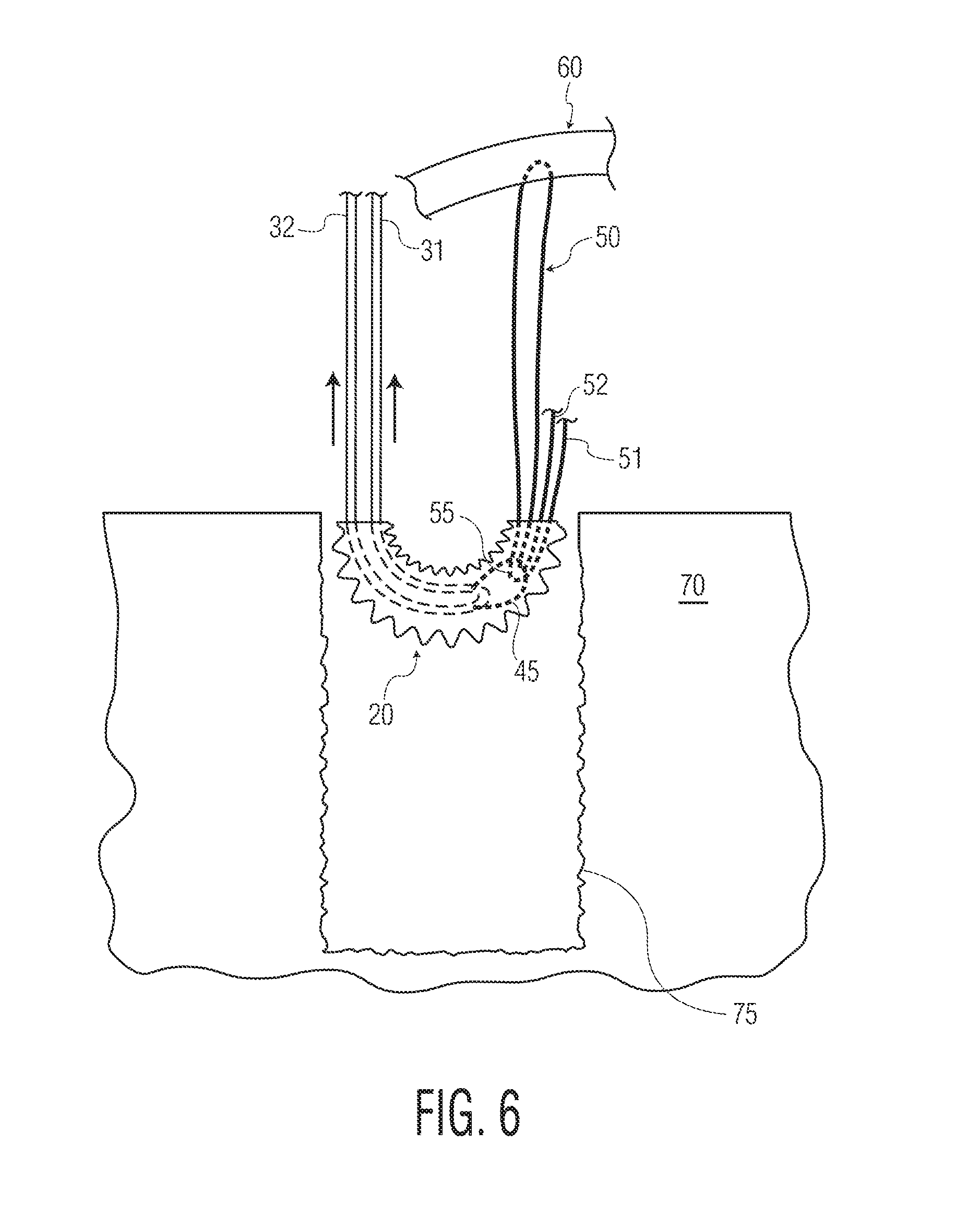
FIG. 6 illustrates another step of the method embodiment of FIG. 5.
FIGS. 7A and 7B illustrate an additional, optional step of the method of FIGS. 5 and 6.
FIG. 8A illustrates yet another step of the method of FIGS. 5-7.
FIG. 8B is a representative view of the step of FIG. 8A illustrating how such a method would be performed through a cannula during arthroscopic repair.
FIG. 9A illustrates yet a further step of the method of FIGS. 5-8.
FIG. 9B illustrates a step of a method of use or assembly utilizing a filamentary assembly or system, a portion of such assembly or system illustrated in FIG. 4B.
FIGS. 10A and 10B illustrate various embodiments of methods of use or assembly.
FIGS. 11A-C illustrate yet another embodiment of a method of use or assembly.
FIGS. 12A and 12B illustrate a further embodiment of a method of use or assembly.
DETAILED DESCRIPTION
The fixation devices, assemblies, systems, kits and associated methods of use, manufacture and assembly, of the present invention are intended for use in the repair, reattachment, replacement or otherwise securement of tissue, including both hard tissue (i.e., bone or the like) and soft tissue. Soft tissue may be, for example, meniscus, cartilage, capsule, ligaments and tendons, replacement grafts of any of these soft tissues, or the like. While many of the exemplary methods disclosed herein are directed towards the use of the filamentary fixation devices, assemblies and systems as a suture anchor for implantation into a bone hole, other uses, some of which are described herein, are also envisioned. As used herein, "proximal" or "proximally" means closer to or towards an operator, e.g., surgeon, while "distal" or "distally" means further from or away from the operator.
As used herein, the term "filament" or "filamentary" is defined as a suture or other thread-like material. Such filaments may be constructed of synthetic material (e.g., PLGA, UHMWPE (ultra high molecular weight polyethylene), polyester, PEEK, Nylon, polypropylene, aramids (for example, Kevlar.RTM.-based fibers) or the like, or blends thereof), organic material (silk, animal tendon, or the like or blends thereof), or blends of both one or more organic materials and one or more synthetic materials. Alternatively, filaments may include thin metal wires. While any of these materials may be used, it is preferable, and is disclosed herein, that the various filaments or filamentary aspects of the present invention be constructed out of suture, such as UHMWPE, polyester or blends thereof.
In one embodiment, illustrated in detail in FIG. 1A, a filamentary fixation device, assembly or system, designated as filamentary fixation assembly 10, of the present invention includes a filamentary sleeve 20, a filamentary shuttle 30 and a length of filament 50.
The filamentary sleeve 20 includes a generally cylindrical shape along a longitudinal axis, defined by a first end 21 and a second end 22, and a hollow pathway 23 extending therethrough along the longitudinal axis. While this filamentary sleeve 20 is one embodiment, it is envisioned that alternative configurations of the sleeve 20 may also be incorporated into the various assemblies, systems, and methods, and may include alternative shapes, sizes, or features as desired, one example of which is shown in FIG. 1B, discussed below. Additional examples of alternative configurations are disclosed in U.S. Provisional Application No. 61/679,336, filed Aug. 3, 2012, U.S. application Ser. No. 13/303,849, filed Nov. 23, 2011, Ser. No. 13/588,586, filed Aug. 17, 2012, and Ser. No. 13/588,592, filed Aug. 17, 2012, and U.S. Pat. Nos. 5,989,252 and 6,511,498, the entireties of which are incorporated by reference herein as if fully set forth herein and all of which are assigned to the same entity as the present application. Another exemplary filamentary sleeve for use in the present invention is the ICONIX.TM. line of filamentary fixation products (Howmedical Osteonics, Mahwah, N.J.). Other alternative configurations are also envisioned. For example, the sleeve 20 may be constructed by braiding multiple filaments together, such that the sleeve is a braided or woven structure.
The filamentary shuttle 30 includes a first end or tail 31 and a second end or tail 32, a length therebetween, and an interior passageway 33 along at least a portion of the length. The shuttle 30 may also include at least two openings 36, 37, and optionally at least four openings 36, 37, 38, 39 (as in FIG. 1), which extend through a sidewall from the interior passageway 33 to an outer surface 34 of the shuttle. As the shuttle 30 is preferably constructed from a length of suture having a hollow core, the interior passageway 33 would extend along the entire length of the shuttle filament 30. However, if the shuttle is constructed of another material, or is formed from a unique braid, or the like, the passageway may not extend the entire length of the shuttle, though it should at least extend along the length of the shuttle spanning the distance between the at least two openings, or at least four openings, if four openings are present (as illustrated in FIG. 1), for reasons discussed further below. Shuttle 30 can also include a structure for engaging the length of filament 50 (described in detail below), such as a loop structure as exemplified by loop configuration 35.
Additionally, an inner filament 40 can be positioned within at least a portion of the interior passageway 33 of the filamentary shuttle 30. As illustrated in FIG. 1, for example, the inner filament 40 can extend through the passageway 33, from end 31 and towards the loop configuration 35, and out of opening 36. The inner filament 40 can continue outside of the passageway 33 and to opening 37, forming a structure for engaging the length of filament 50 (described in detail below) outside of the passageway 30 and at a position on or adjacent to the loop configuration 35. The inner filament 40 can then pass through opening 37 and back into passageway 30, towards end 32. This engaging structure can be a loop structure as is exemplified by filament eyelet 45. The inner filament 40 first and second ends 41, 42 may remain in position within the inner passageway 33, may extend to and through the first and second ends 31, 32 of the shuttle 30, or, as illustrated, exit the passageway 33 through additional openings 38, 39.
The filamentary shuttle 30, with or without the inner filament 40 present, in turn, can be folded over itself, as in FIG. 1, forming the loop configuration 35, with the first and second ends 31, 32 extending therefrom. In this position, the shuttle 30 can be positioned through the hollow pathway 23 of the filamentary sleeve 20 such that at least a portion of the loop configuration 35 is positioned outside the pathway 23 at the first end 21 of the filamentary sleeve, and the first and second ends 31, 32 extend through the pathway 23 and out past the second end 22 of the filamentary sleeve. The shuttle 30 may be positioned as such, for example, by the use of a separate length of wire or suture (not shown) positioned through the pathway 23 and having a loop or hook on one end. The shuttle 30 may be engaged with the loop or hook and pulled into and through the sleeve 20 to a position as illustrated in FIG. 1. One example of such use of a loading wire or suture is illustrated in the heretofore referenced '586 and '592 applications, incorporated by reference herein.
FIG. 1 also illustrates the length of repair filament 50 having first and second free ends 51, 52. As discussed in detail below, the length of repair filament 50 and/or plurality of repair filaments 50 are used to engage the soft tissue (as in FIG. 4a), or otherwise apply tension or force to soft tissue, and secure tissue by similarly engaging the filamentary sleeve 20 in a manner which does not require any knots.
It is preferred, as illustrated in FIG. 1 and throughout this disclosure, that the filamentary sleeve 20 be constructed of a filament which has a larger inner diameter than an outer diameter of the filamentary shuttle 30, and that the shuttle 30 has a larger outer diameter than either of the inner filament 40 and the length of filament 50. Moreover, the inner diameter of the passageway 33 of the shuttle should be equal to or greater than the outer diameter of the inner filament 40. Furthermore, the diameter of the length of filament 50 may be about one half or less of the diameter of the hollow pathway 23 of the sleeve 20, which may allow for simplified maneuvering of the filament 50, relative to the sleeve 20, during manipulation in the various methods described below. However, such sizes may be dependent upon the desires of the operator and whether a tighter or looser fit is desired between the various filamentary elements of the present invention. In one example, the filamentary shuttle 30 may be #5 suture, the inner filament 40, if present, may be #1 suture, and the length of repair filament 50 may be #2 suture (which is normally used for working or repair suture in the orthopedic field).
FIG. 1B illustrates another embodiment of a filamentary fixation device including a sleeve 120 and a filamentary shuttle 130. It should be understood that either sleeve 20, 120 may be used with either shuttle 30, 130, or any variations or combinations thereof. Sleeve 120 includes first and second ends 121, 122, similar to shuttle 20, though shuttle 120 also includes first and second openings 126, 127 through which the shuttle 130 may be positioned such that, between openings 126, 127, the shuttle 130 is positioned outside of pathway 123. As discussed in the various incorporated references, cited above, positioning the shuttle 130 in this manner can reduce the overall size of the filamentary construct (i.e., sleeve and shuttle) on the end of an inserter (as in FIG. 2) thereby allowing the construct to be positioned in a smaller bone hole or otherwise to be more easily maneuvered in small spaces, such as through a cannula. Specifically, with shuttle 130 positioned outside of sleeve 120 at the point where the construct is folded onto an instrument allows the sleeve and shuttle to be vertically stacked on an inserter separately rather than being an integrated body
The filamentary shuttle 130 illustrated in FIG. 1B differs from shuttle 30 in that shuttle 130 is not folded onto itself (see FIG. 1A versus FIG. 1B) and thus the shuttle 130 is positioned through the sleeve 120 such that a first end 131 is positioned outside one end 122 of the sleeve 120 while the second end 132 is positioned outside the other end 121 of the sleeve 120. FIG. 1B also illustrates how an inner filament 40 would be positioned in such a shuttle 130. In this embodiment, inner filament 40 is double over onto itself and positioned through at least a portion of passageway 133 through sleeve 130. Inner filament 40 may extend out through second end 132 of shuttle 130 to form a structure for engaging filament 50, such as a loop structure exemplified by eyelet 45. Alternatively, eyelet 45 of this embodiment could also be formed by passing the inner filament through the sidewall of the sleeve 130, towards second end 132, in similar fashion as is illustrated in FIG. 1A. While the sizes of the various filaments of FIG. 1B can vary as desired, similar to FIG. 1A, in a preferred example the shuttle 130 may be #7 suture, the inner filament 40, if present, may be #1 suture, and the length of repair filament 50 may be #2 suture. Of course, shuttle 130 may be larger than shuttle 30 since shuttle 130 is not being doubled over within the filamentary sleeve.
The embodiment of FIG. 1B is preferred for a few reasons. Having a shuttle 30 that originates as a straight filament as seen in FIG. 1B rather than the folded over configuration shown in FIG. 1A could offer the advantage of minimizing the risk of the shuttle becoming tangled or inadvertently ensnaring other filaments, tissue, or surgical equipment that are adjacent to it during various steps of a surgical procedure such as engaging of filament 50 and subsequent passing or shuttling of filament 50, particularly through a cannula in arthroscopic applications.
It should be noted that while the sleeve 120 and shuttle 130 of FIG. 1B is a preferred embodiment, and can be used in any of the illustrated and envisioned embodiments of the present invention, sleeve 20 and shuttle 30 will be illustrated and used in the exemplary embodiments herein for reasons of clarity and simplicity.
FIG. 2 illustrates one embodiment of how the filamentary fixation assembly 10 can be used in conjunction with an instrument 80. As illustrated, the sleeve 20 is folded around a distal end of the instrument, which has a shape of a blunt end, flat end, or a "field goal" post (i.e., the sleeve fits between the "goal posts"). When positioned on the instrument, the filamentary shuttle 30 should be sufficiently long such that both the loop configuration 35 and the first and second ends 31, 32 can extend proximally to or towards the handle 85, and can be held at such a position by the operator or by some connection point on the instrument 80. As will be discussed below, positioning the shuttle 30 in such a manner is useful for the operator, particularly for arthroscopic applications. The instrument 80 may be used to position the filamentary assembly 10 in a specific anatomical location, such as towards and into a bore hole 75 in a bone 70, e.g., as illustrated, a bore hole in a glenoid for the repair of labrum tissue 60. Potential instrumentation for use with the assembly, particularly for arthroscopic repairs, would also include a cannula (an example of which is illustrated in FIG. 8B as cannula 88), as is known in the art for arthroscopic applications, through which the assembly 10 and instrument 80 would pass through to the surgical site in the anatomy. Such instrumentation, including exemplary instruments 80, cannulas 88 and the use thereof, are described in the heretofore referenced applications, such as the '586 and '592 applications, incorporated by reference herein. In one example, the cannula may have an inner diameter of about 3.3 mm, which may be suitable for insertion of either or both a 2.3 mm drill (to prepare a bore hole) and instrument 80 with assembly 10.
In another embodiment, the present invention is a system for the repair of tissue including the above assembly 10. The system may further include instrument 80 as well as additional instrumentation such as a cannula, a drill or reamer (not shown) for preparation of a bore hole in bone (if required), needles and/or trocars which may be used to position the length of filament 50 around or through tissue, and a loading wire or suture as discussed above for positioning the shuttle 30 within the sleeve (though, it is preferred that the shuttle 30 be positioned within the sleeve 20 at time of manufacture, and thus would arrive at the operator packaged as such).
In a further embodiment, the present invention is a kit including at least one filamentary sleeve 20, at least one filamentary shuttle 30, and a plurality of lengths of filaments 50 (or filaments 150, or any combination of filaments 50, 150). The plurality of filaments 50 can vary in length, color, diameter, strength, or the like, or, they can be identical to one another. In one example, such a kit may be packaged and offered to operators as a kit for labrum repair, in which a plurality of filaments 50 may be used with a single sleeve 20 and shuttle 30 (packaged as a unit (as in FIG. 1), or separate.
Such a kit may also include, for example, a plurality of sleeves 20 and shuttles 30 of varying length, width, material, color, or the like, or of identical characteristics. Such a kit could also include various configurations of sleeves 20, 120 (or other variations) and shuttles 30, 130 (or other variations) from which an operator can select the best types for a particular surgical procedure. Optionally, some or all of the plurality of shuttles can include an inner filament 40, and thus, a filamentary eyelet 45. In one further example, a variation of a kit could include a plurality of sleeves of various sizes, and at least one shuttle, which could be used, for example, for larger labrum tears which require multiple reattachment points on both the glenoid and labrum.
In another embodiment, a kit of the present invention may be specific to, for example, meniscal repair, and would include a plurality of filamentary sleeves 20 positioned on a single filamentary shuttle 30 or, alternatively, each on an individual filamentary shuttle 30. The kit can also include at least one length of repair filament 50, and thus, the filament 50 may be used with all of the sleeves 20 together (e.g., the sleeves operate as multiple "back stops" for multiple passes of the filament 50 through the meniscus tissue), or a single filament 50 can be provided for use with each sleeve 20 individually.
Such kits can also include additional components, such as at least one instrument 80, as well as additional instrumentation such as a cannula, a drill or reamer (not shown) for preparation of bore hole in bone (if required), needles (particularly for meniscus repair) and/or trocars which may be used to position the length of filament 50 around or through tissue (or, for example, through meniscus tissue and a tear through the meniscus tissue), and a loading wire or suture as discussed above for positioning the shuttle 30 within the sleeve (though, it is preferred that the shuttle 30 be positioned within the sleeve 20 at time of manufacture, and thus would arrive at the operator packaged as such).
While filamentary fixation devices, assemblies, systems and kits are preferred, it is also envisioned that other fixation devices, other than filamentary fixation devices such as filamentary sleeve 20, 120, can also be used in any of the devices, systems, kits and assemblies and methods of use and assembly described or envisioned herein. For example, a tubular, flexible, plastic implant can replace the sleeve and be used. Alternatively, traditional suture anchors (as in FIG. 11A-C) could also be used.
Certain exemplary embodiments of methods of assembly and use will now be described. While such methods will be described in terms of a repair and reattachment of labrum tissue 60 to a glenoid 70, it is envisioned that the assembly 10 of the present invention may be performed in other anatomical locations and for other anatomical repairs such as, for example, acetabular labral repair, meniscal repair, rotator cuff repair, and the like. Similarly, it is envisioned that the filamentary fixation devices, assemblies and systems of the present invention may also be used in bone-bone repair such as reducing fractures, reattaching bone fragments and chips to bone, and for the repair of bone-bone joints such as the acromioclavicular joint. However, for ease of reference, the methods of assembly and use will be directed towards the repair of soft tissue using the filamentary fixation assembly 10, and specifically, the deployment of the filamentary sleeve 20 into a bore hole 75 in the glenoid 70 for repair and reattachment of labrum tissue 60, unless stated otherwise.
It should be understood that FIGS. 3A-8A and 9A-9B illustrate certain embodiments of methods of assembly and use as a close-up, simplified illustration. FIG. 8B, on the other hand, provides an illustration of how any of these particular methods would likely be performed in an actual arthroscopic surgical method--i.e., through a cannula 88, with many of the filament manipulation steps occurring outside of the surgical site in plain view of the operator. It should be understood that FIGS. 3A-8A and 9A-9B are presented in such a way merely for the sake of clarity and that each of the illustrated steps can and, in a preferred embodiment should, be performed through a cannula, as in FIG. 8B.
Generally, the present invention, in one embodiment, includes a method of securing tissue including passing or positioning a length of filament 50 around or through tissue to be secured, implanting a filamentary sleeve 30 into an another tissue (such as bone, another portion of the tissue to be secured, other adjacent tissue, or the like) and passing at least a portion of filament 50 through the sleeve to form a one-way cleat. As will be described below, the one-way cleat secures the tissue, through filament 50, to the filamentary sleeve and the another tissue. In a specific example, the filament 50 is positioned around or through a labrum tissue and the filament sleeve is positioned in the glenoid, such that the assembly of the filament and sleeve secures the labrum tissue to bone.
FIGS. 3A and 3B illustrate one embodiment of a method of repairing tissue of the present invention. Specifically, FIGS. 3A and 3B of positioning of the assembly 10, specifically the filamentary sleeve 20. As will be discussed further below, while the preferred embodiment of the present invention includes placement of the assembly 10 into a bore hole 75 in a bone 70, the assembly may be positioned in other anatomical locations other than within a bone.
Continuing with this embodiment, FIG. 3A illustrates (with the surrounding soft tissue and instrument 80 removed for clarity) the initial positioning and a filamentary sleeve 20, with filamentary shuttle 30 therein, into the bore hole 75 in the bone 70. For example, the bone may be a glenoid, and the bore hole 75 may be at an anatomical position for reattachment of torn labrum tissue 65 thereto. FIG. 3B illustrates deployment of the sleeve 20 within the bore hole 75. Such deployment is achieved by the operator grasping and tensioning, in a proximal direction, the first and second ends 31, 32 and the loop configuration 35. Such deployment of the sleeve 20 renders the sleeve 20 fixedly secured within the bore hole such that the filamentary shuttle 30 may be used to pass the length of filament 50 therethrough while the sleeve 20 remains within the bore hole 75. Of course, such deployment may alternatively be only a partial deployment wherein the sleeve 20 partially deploys, and as such, the sleeve is removeably secured within the bore hole. However, from a practical standpoint, it is preferred that the operator fully deploy the sleeve 20 such that, during the tensioning step of the filament 50 and tissue 60, the sleeve 20 does not inadvertently exit the bore hole, though it is appreciated that the tensioning of the filament 50 and tissue 60 may result in additional deployment (e.g., crushing or bunching of the sleeve 20, or possible movement of the sleeve relative to the surrounding bone). Such deployment is discussed further in the heretofore referenced applications incorporated by reference herein.
With the filamentary sleeve 20 in the bore hole 75, and deployed towards or into the second configuration (FIG. 3B), the sleeve 20 is now ready for engagement with the length of filament 50. The length of filament, either before or after implantation of the sleeve 20, is passed around or through the soft tissue 60, and specifically through the tissue at or adjacent to tear 65, as in FIG. 4A, such that the first and second free ends 51, 52 extend from the tissue 60. If desired, the filament 50 could be passed through tissue more than once; for example, passed twice to create what is commonly called a mattress stitch. Continuing with the example of an arthroscopic repair, the ends 51, 52 should be brought outside the surgical site and to the loop configuration 35 of the filamentary shuttle which is also already positioned outside the surgical site (as is was originally positioned adjacent handle 95 of instrument 80, though by this point in the procedure, typically prior to deployment of sleeve 20, the inserter is removed from the cannula and surgical site). The ends 51, 52 may then be engaged with the shuttle 30, such as by being passed through a loop structure, such as the loop configuration 35 or alternatively, if present, the filament eyelet 45 of the inner filament 40. Of course, if shuttle 130 and were used in this method, the filament ends would be engaged by the eyelet 45 as this embodiment does not include a separate loop configuration on the sleeve 130 itself.
In one alternative embodiment, illustrated in FIG. 4B, the length of filament 150 may include a loop 152 on one free end of the filament. As illustrated, the loop 152 may be used in such a way that the filament 150 may be passed through or around tissue 60, and free end 151 may be passed through the loop 152 and tensioned to draw the loop 152 against the tissue 60 in a "luggage tag" configuration. Of course, in this instance, the filament 150 would only have one end 151 extending from the tissue rather than two ends 51, 52 as when the filament 50 is used. However, a filament 150 including two lengths of filament extending from the loop 152 may also be used to provide the operator with two free ends even when a luggage tag arrangement is used. Examples of such filaments are disclosed in U.S. application Ser. No. 13/441,290, filed Apr. 6, 2012, the entirety of which is incorporated by reference herein as if fully set forth herein, and which is assigned to the same entity as the present application.
Regardless of which length of filament 50, 150 is used (and continuing as to the length of filament 50 for discussion purposes), FIG. 5 illustrates, in representative fashion only, passing the first and second free ends 51, 52 through the filament eyelet 45. As it is preferable to have the loop configuration 35 or filament eyelet 45 adjacent the handle 85 of the instrument 80, this step may be preformed outside of the surgical site (though instrument 80 is typically removed at this point) such that the free ends 51, 52 are brought outside the surgical site to the loop configuration 35 or filament eyelet 45. However, it is envisioned that this step, or any of the steps of this method, may alternatively be performed within the patient and at the surgical site with the assistance of an endoscope or other viewing instrumentation as known in the art.
FIG. 6 illustrates the next step of drawing the length of filament 50 into the filamentary sleeve 20 by pulling on the filament end 31, and 32 (specifically as to shuttle 30), of the shuttle 30 (and ends 41, 42 of inner filament 40, if present). As the loop configuration 35 or filament eyelet 45 travels through the sleeve 20, a second loop configuration 55 is formed on the length of filament, wherein in this position, the length of filament is folded over itself and is positioned through the sleeve such that at least a portion of the second loop configuration 55 is positioned outside the sleeve at end 22 of the filamentary sleeve, and the two or more filament free ends 51, 52 extend through the sleeve. Continuing with the example of an arthroscopic surgical procedure, the length of filament 50 may have a sufficient length such that the second loop configuration 55 as well as the two filament free ends 51, 52 may extend out of the surgical site proximally through a cannula (if present, see FIG. 8B), and to the operator, though alternatively, even in arthroscopic procedures, the loop and free ends may remain within the surgical site.
With the filamentary sleeve 20 fully deployed prior to this step, it is noted that, commonly, the pathway 23 crushes or compresses along with the entirety of the sleeve 20 as the sleeve deploys (FIG. 3b). Such compression may make it difficult to slide filaments through the pathway 23. In light of this potential issue, the filamentary shuttle 30 has an equivalent or preferably a larger diameter than the folded length of filament 50 (as discussed above, and also shuttle 130 would similarly have a larger diameter than filament 50). The differences in thickness allow the shuttle 30 to act as a larger placeholder within the pathway 23 during deployment, such that a suitably sized pathway can be preserved to provide for simplified passing or shuttling of the filament 50 through the sleeve 20, particularly since both ends 51, 52 of the filament 50 will be doubled over themselves and passed through the sleeve 20 (unless filament 150 is used, in which case only a single free end 151 would be doubled over itself). Similarly, the use of the inner filament 40, and eyelet 45, may also provide for simplified passing of the filament 50 into and through the sleeve because, with the filament 50 wrapping around the eyelet 45 rather than the loop configuration 35, a smaller diameter at the intersection of the filament 50 and inner filament 40 is maintained. This benefit may also be realized relative to shuttle 130, which, while not folded onto itself, still has a large diameter.
FIGS. 7A and 7B illustrate an optional step performed if the inner filament 40 is used (again, these steps apply equally to both examples of sleeve 30, 130 illustrated in FIGS. 1A and 1B). Following the positioning of the length of filament 50 through the filamentary sleeve 20, the filamentary shuttle 30, or outer filament, may be separated from the inner filament 40 such that the inner filament 40 can be removed from the second loop configuration 55. Alternatively, the inner filament may be simply cut, or, if ends 41 and 42 are accessible (i.e., projecting from openings 38, 39), the operator may simply pull on one of the ends 41, 42 to slide the inner filament 40 from the shuttle 30 and second loop configuration 55.
Regardless of whether the inner filament 40 is used, FIGS. 8A and 8B illustrate the next step once the filamentary shuttle 30, and optionally inner filament 40, is removed from the second loop configuration 55. Again, the second loop configuration may remain within the surgical site or may extend proximally outside of the surgical site and towards the operator, as in FIG. 8B, which is preferred. In either situation, the free ends 51, 52 of the length of filament 50 are then maneuvered through the second loop configuration 55. Such a configuration would also allow for multiple filaments to be positioned in this fashion. Alternatively, if filament 150 (or multiple filaments 150) is used, only a single free end 151 of each filament 150 will be passed through a second loop configuration 155.
As noted above, FIG. 8B provides a representative view of how this embodiment of the method can be performed in an arthroscopic surgical procedure, with the steps being performed outside of the surgical site, and further, any of the other steps of this embodiment, as have been described, can also be performed through a cannula 88 as in FIG. 8B.
FIG. 9A illustrates the completed configuration of assembly 10 in which the tissue 60 is secured, reattached, or the like. In maintaining the example of labrum tissue repair, the completed configuration of the assembly 10, within the glenoid, secures the labrum back against the surface of the glenoid to compress the tear 65. Specifically, the free ends 51, 52 (together or alternating by cycling between one free end and the other) are tensioned such that the second loop configuration 55 travels towards and into the pathway 23 of the filamentary sleeve 20, the length of filament 50 applies tension to the tissue 60, and the free ends, passed through the second loop configuration, are secured within the second loop configuration. Optionally, the second loop configuration 55 may be forced towards and into the pathway 23 of the filamentary sleeve 20 with a knot pusher or the like, or by pulling the free ends 51, 52 apart from each other. The second loop configuration, as tensioned, effectively forms a one-way cleat such that the free ends 51, 52 may be tensioned further, but any tension applied on the assembly by the tissue 60, i.e., in a direction opposite the free ends 51, 52, would only force the second loop configuration into or up against the sleeve 20 and thereby prevent the free ends 51, 52 from loosening.
Similarly, FIG. 9B illustrates the completed configuration of assembly 10 in which the tissue 60 is secured, reattached, or the like, as above, though including the length of filament 150 (or filaments 150) rather than filament 50. Similar to the assembly of FIG. 9A, the second loop configuration 155 as tensioned, effectively forms a one-way cleat such that the free end 51 may be tensioned further, but any tension applied on the assembly by the tissue 60, i.e., in a direction opposite the free end 151, would only force the second loop configuration into or up against the sleeve 20 and thereby prevent the free end 151 from loosening. The use of filament 151 may reduce the size of the overall repair, and possibly, even the size of the bore hole, as compared to the use of filament(s) 50.
It is envisioned that, if filament 150 is used, it would be easier to utilize multiple filaments 150 (not shown) which may be passed through the tissue 60 at multiple points, as desired based on the position, size and type of tear 65 to the tissue. Each of the filaments 150 may then be directed to the loop configuration 35 and positioned through a single sleeve 20 (or multiple sleeves of course) and tensioned as above. In another embodiment, such as in a rotator cuff repair, it would be common for multiple filaments 50 (2-4 such filaments 50, for example) to be shuttled through a single sleeve 20. For the glenoid repair described above, multiple filaments 50 could be used, though filaments 150 would be preferred as they each would include only a single free end 151 doubled over itself in the sleeve, and thus more filaments 150 may be positioned in a single sleeve 20 than filaments 50.
Following sufficient tensioning of the filament 50, 150, the excess portion of the filament free end 151, or ends 51, 52, may be cut away and the surgical site closed as is known in the art. Such an embodiment can achieve repair and attachment of soft tissue 60 without the need to tie any knots, and thus, the repair is simple to perform for an operator, is free of any knots which may loosen or come untied or interfere with anatomy, and is sufficiently strong to hold the soft tissue in place until the tissue 60 heals to the repair site.
In one alternative embodiment, the result of which is illustrated in FIG. 10A, assembly 10 may be used to repair other types of soft tissue 160 whereby the filamentary sleeve 20 is not positioned within a bore hole in a bone, but instead is positioned merely to abut an edge or surface of a soft tissue to be repaired. Such a repair may be particularly useful in the repair of a tear 165 in meniscus 160, or alternatively, bone-bone applications to reduce one bone or fragment to another bone or fragment. Similar to the above embodiment, length of filament 50 is passed through the meniscal tissue, and through the tear 165, as is known in the art, to, preferably, an exterior side of the meniscus where the sleeve 20 will be positioned. The filament 50 is stabilized in the tissue by wrapping around the opposite edge of the tissue to form a u-turn 58. The u-turn may be buttressed using a back stop such as a button anchor, another sleeve 20, or other implant as is known in the art. The filament 50 may be positioned through the pathway 23 of the sleeve 20, as explained above, and the free ends 51, 52 may be tensioned to reduce the second loop configuration 55 and tension the tissue to compress the tear 165. As before, the second loop configuration 55 effectively forms a one-way cleat to secure the tissue, sleeve and filament to one another and complete the repair.
FIG. 10B illustrates an alternative embodiment where a second filamentary fixation device, filamentary sleeve 20', is inserted through the soft tissue and deployed on the exterior side of the meniscus, featuring an integrated filament 150 where end 151 is routed through a separate sleeve 20 as similarly shown in FIG. 9B. As illustrated, the loop 152 of filament 150 would be positioned through the sleeve 20' and the first free end 151 positioned through the loop would be tensioned to deploy sleeve 20' and secure the sleeve 20' against the external side of the meniscus. As in FIG. 9A, the free end 151 may then be passed through the meniscus in any configuration desired (either during the surgical procedure or pre-packaged with the desired filament routing). Illustrated is a preferred configuration, in which the free end 151 passes through the tissue to a position adjacent the tear 165, passing over the tear and re-entering the meniscal tissue at u-turn 58. The free end 151 can then navigate through the tear 165 and the tissue 160 to a second position and second sleeve 20. The filament may then be passed through sleeve 20 and a one-way cleat may be forms as described above. Optionally, and assuming the filament 150 has sufficient length, the free end 151 may pass through the meniscal tissue, and through tear 165, again and to a third or more sleeve, another backstop, tied into a knot, or the like. Also, of course, sleeve 20' may be replaced by another sufficient backstop structure, may be tied into a knot, or the like. In another alternative, the free end 151 and loop 152 may simply be positioned through the meniscus to form the "luggage tag" configuration as disclosed above, from where the free end 151 may then proceed to sleeve 20 or other anchor.
In a preferred embodiment, for example, the sleeves 20, 20' and filament 150 would be pre-fabricated such that both sleeves are positioned along the filament as illustrated in FIG. 10B. The sleeves would then be positioned on an instrument, such as an elongated needle, such that the needle may puncture the meniscus tissue in two places (illustrated as the two openings through which filament 150 pass) and deploy the two sleeves 20, 20' as shown. Once puncturing and positioning the two anchors, the free end 151 may simply be tensioned to deploy the two sleeves, form the one-way cleat with second loop configuration 155, and compress the meniscus tear 165 to complete the procedure. Essentially, such a method would remove the need for a operator to route the filament 150 through the tissue and through the sleeves. Instead, with the filament 150 already positioned through the sleeves, the needle instrument can simply puncture the tissue and position the sleeves as shown, which may result in a more efficient and reliable repair.
In another embodiment, the above method may be performed using a system including a filamentary fixation device including first sleeve 20, a second sleeve 20' and a filament 150, wherein the filament is positioned through at least a portion of the first sleeve and at least a portion of the second sleeve, and an instrument (not shown) adapted to deploy the filamentary fixation device to repair a tissue.
It is envisioned that multiple sleeves 20 may be used as necessary dependent on the position, size and type of tear in tissue amenable to such a repair. For example, using the aforementioned kit disclosed above, a single filamentary shuttle 30 may be positioned through multiple sleeves 20 (not shown), or multiple shuttles may be positioned through multiple sleeves, such that the filament 50, 150 (or filaments) can be positioned through the sleeves and secured within each one. One preferred configuration would include a sleeve at the sides of the tissue after each pass of the filament through the meniscus, such that each pass of the filament may be tensioned to compress the tissue along each pass.
In yet another embodiment, the present invention includes a method for the repair of a tissue, such as a rotator cuff. As illustrated in FIG. 12A, a filament 150 including two tails 151 and 151' extending from the loop 152 is positioned through tissue 260 in a "luggage tag" configuration, as discussed above. Such a filament, and configuration through tissue, is described in the '290 application incorporated by reference above. FIG. 12A illustrates one example where tissue 260 is a rotator cuff and 265 is a rotator cuff tear for ease of reference, though this embodiment is not limited to this anatomy. From the "luggage tag" configuration, the first free end 151 is shuttled through a sleeve 20 as described above to create a one-way cleat with second loop configuration 155. During this step, sleeve 20 would be implanted and deployed in bore hole 75 (as described above) but is shown outside for clarity of the filament routing of the assembly. Then, the second free end 151' is shuttled through a second sleeve 20' as described above to create another one-way cleat. Again, during this step, sleeve 20' would be implanted in bore hole 75' (as described above) but is shown outside for clarity of the filament routing of the assembly. It should be noted that bore holes 75, 75' are considered lateral bore holes for rotator cuff repair, as known in the art. The two free ends 151, 151' would then be tensioned to apply tension to the rotator cuff which may pull the cuff laterally towards bore holes 75, 75'. Alternatively two separate and independent filaments 50 (or filaments 150 with a single tail each) could have been passed through the rotator cuff and secured to the two separate holes 75, 75' but the luggage tag offers additional tissue compression or engagement with the same amount of filament passing steps through the rotator cuff tissue.
FIG. 12B illustrates an alternative configuration of FIG. 12A in which filament 150 (with two tails 151 and 151') is instead positioned through a third filamentary fixation device 20'', positioned in bore hole 75''. Bore hole 75'' is considered a medial bore hole, which, once the repair is complete will be positioned beneath the rotator cuff tissue, as is known in the art. The third device 20'' can be an ICONIX.RTM. filamentary device (mentioned above). The addition of the device 20'' can allow for the luggage tag configuration of loop 152 and free end 151 to compress the tissue down directly to the bone at the desired hole location 75'' which may result in an improved repair.
FIGS. 11A-C illustrate a further embodiment of the present invention including a method of securing tissue. Generally, this method includes steps which are similar to the above-discussed embodiments, though the fixation device has been replaced--such that sleeve 20 has been replaced by a traditional suture or tissue anchor 120. One example of anchor 120 may be a TwinLoop.RTM. anchor (Howmedica Osteonics, Mahwah, N.J.), which includes two suture loops 121, 122 for attachment of a filament, and tissue, thereto. Additionally, this embodiment utilizes length of filament 150, though filament 50 may also be used as desired. As illustrated, anchor 120 can be positioned in a bore hole 75 in bone 70 or threaded directly into bone as is known in the art. In an alternative embodiment, the anchor 120 itself may include a U-shaped passage therethrough rather than suture loops 121, 122, such that the filament (and shuttle) can be positioned through the U-shaped passage in a similar manner. For example, if suture loops 121, 122 are removed from the TwinLoop.RTM. anchor, the anchor includes such a U-shaped passage which may be used. While either embodiment is envisioned, the embodiment using loops 121, 122 will now be described.
FIG. 11A illustrates the first step, as in FIGS. 4A and 5 above, where filament 150 is directed to and threaded through loop configuration 35 of filamentary shuttle 30, which is positioned through suture loops 121, 122. As with any of the disclosed embodiments, shuttle 130 (and optionally inner filament 40) may also be used. FIG. 11B, similar to FIGS. 6 and 7A, above, illustrate tensioning shuttle ends 31, 32 to pull filament 150 into and through suture loops 121, 122 to form a second loop configuration 155. The shuttle may be withdrawn from the second loop configuration 155 and discarded. Finally, in FIG. 11C, as in FIGS. 8A and 8B, free end 151 is passed through the second loop configuration 155. The free end 151 can continue to be tensioned, as in FIGS. 9A and 9B above, to compress loop configuration 155 and form the aforementioned one-way cleat as to free end 151. Suture loops 121, 122 must be sufficiently small to create the one-way cleat but sufficiently large to allow shuttling of filament 150. Moreover, as with the embodiments discussed above, it is preferred that these various steps be performed through a cannula (as in FIG. 8B) in an arthroscopic manner, such that, for example, the loop configuration 35 and ends 31, 32 of shuttle 30, free end 151, and formed loop configuration 155 are all positioned proximally through the cannula and outside to the operator such that each of these steps can be performed outside of the surgical site. Also, it is envisioned that multiple filaments 50, 150 may be used with a single anchor 120, or multiple anchors as desired.
In another embodiment, the present invention includes a system for the repair of soft tissue including at least one filamentary fixation assembly, at least one instrument for insertion of the filamentary fixation assembly, and a surgical procedure. The surgical procedure may include instructions or protocol for using the filamentary fixation assembly and instrument to repair soft tissue. The protocol may include aspects of any of the above-discussed embodiments, though other variations are also envisioned within the scope of the present invention.
In an associated embodiment, the present invention includes a method of providing instructions or information to practice any of the various methods of performing soft tissue repair described herein. For example, the method may include supplying a surgical protocol, or like document, to provide step-by-step instructions for performing any of the method embodiments of the present invention.
Although the invention herein has been described with reference to particular embodiments, it is to be understood that these embodiments are merely illustrative of the principles and applications of the present invention. It is therefore to be understood that numerous modifications may be made to the illustrative embodiments and that other arrangements may be devised without departing from the spirit and scope of the present invention as defined by the appended claims.
* * * * *
D00000
D00001
D00002
D00003
D00004
D00005
D00006
D00007
D00008
D00009
D00010
D00011
D00012

D00013

D00014

D00015

D00016
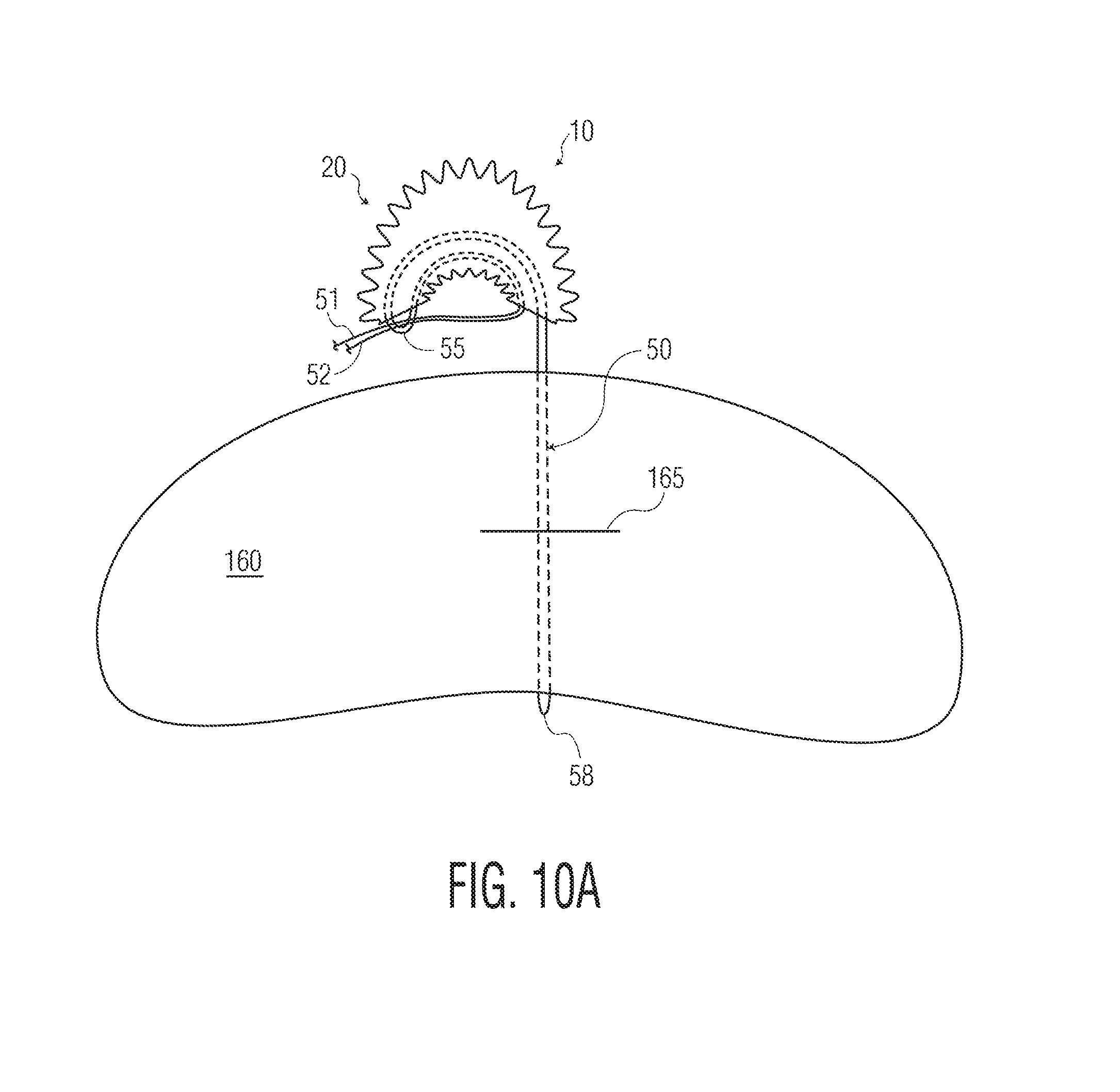
D00017
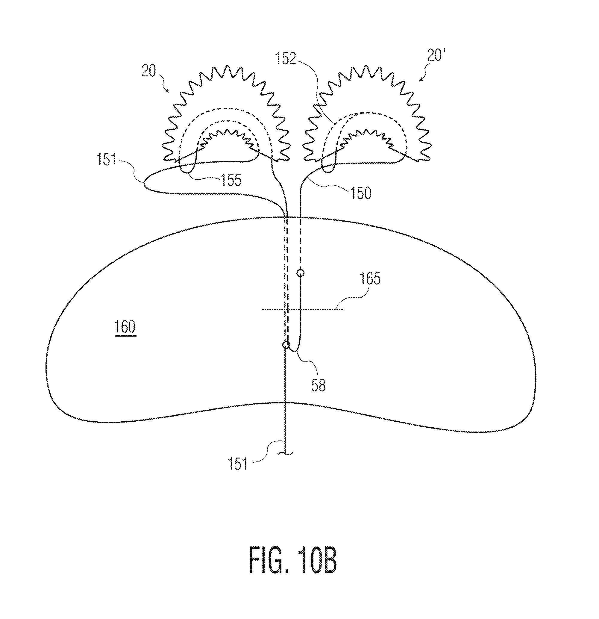
D00018

D00019

D00020
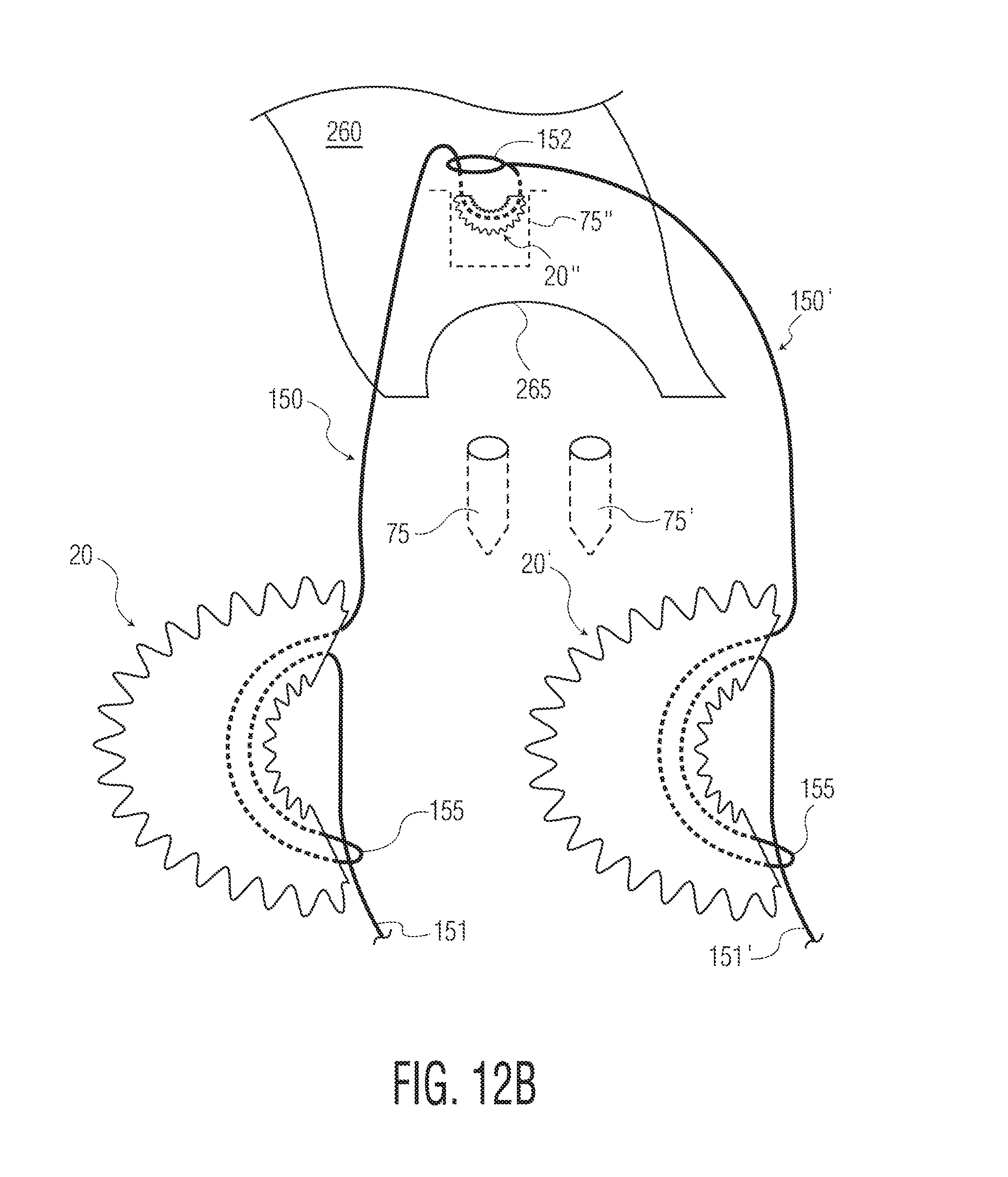
XML
uspto.report is an independent third-party trademark research tool that is not affiliated, endorsed, or sponsored by the United States Patent and Trademark Office (USPTO) or any other governmental organization. The information provided by uspto.report is based on publicly available data at the time of writing and is intended for informational purposes only.
While we strive to provide accurate and up-to-date information, we do not guarantee the accuracy, completeness, reliability, or suitability of the information displayed on this site. The use of this site is at your own risk. Any reliance you place on such information is therefore strictly at your own risk.
All official trademark data, including owner information, should be verified by visiting the official USPTO website at www.uspto.gov. This site is not intended to replace professional legal advice and should not be used as a substitute for consulting with a legal professional who is knowledgeable about trademark law.