Rotation control assembly for a steering column
Bodtker , et al.
U.S. patent number 10,239,552 [Application Number 15/293,900] was granted by the patent office on 2019-03-26 for rotation control assembly for a steering column. This patent grant is currently assigned to STEERING SOLUTIONS IP HOLDING CORPORATION. The grantee listed for this patent is STEERING SOLUTIONS IP HOLDING CORPORATION. Invention is credited to Joen C. Bodtker, Melvin Lee Tinnin.


| United States Patent | 10,239,552 |
| Bodtker , et al. | March 26, 2019 |
Rotation control assembly for a steering column
Abstract
A rotation control assembly for a steering column assembly includes a steering shaft. Also included is a driving tab rotatable with the steering shaft. Further included is a rotating plate surrounding the steering shaft and rotatable relative to the steering shaft, the rotating plate having a driven tab extending from the rotating plate, the driving tab engageable with the driven tab to rotate the rotating plate. Yet further included is an end stop extending from a structure disposed radially outward of the steering shaft and radially positioned to engage the driven tab upon rotation of the driven tab to the end stop, engagement of the driven tab and the end stop limiting rotation of the steering shaft.
| Inventors: | Bodtker; Joen C. (Gaines, MI), Tinnin; Melvin Lee (Clio, MI) | ||||||||||
|---|---|---|---|---|---|---|---|---|---|---|---|
| Applicant: |
|
||||||||||
| Assignee: | STEERING SOLUTIONS IP HOLDING
CORPORATION (Saginaw, MI) |
||||||||||
| Family ID: | 61902589 | ||||||||||
| Appl. No.: | 15/293,900 | ||||||||||
| Filed: | October 14, 2016 |
Prior Publication Data
| Document Identifier | Publication Date | |
|---|---|---|
| US 20180105198 A1 | Apr 19, 2018 | |
| Current U.S. Class: | 1/1 |
| Current CPC Class: | B62D 5/005 (20130101); B62D 1/16 (20130101); B60R 21/203 (20130101) |
| Current International Class: | B62D 5/00 (20060101); B62D 1/16 (20060101); B60R 21/203 (20060101) |
References Cited [Referenced By]
U.S. Patent Documents
| 3420586 | January 1969 | Gerner |
| 4315117 | February 1982 | Kokubo et al. |
| 4337967 | July 1982 | Yoshida et al. |
| 4503300 | March 1985 | Lane, Jr. |
| 4503504 | March 1985 | Suzumura et al. |
| 4561323 | December 1985 | Stromberg |
| 4691587 | September 1987 | Farrand et al. |
| 4836566 | June 1989 | Birsching |
| 4921066 | May 1990 | Conley |
| 4962570 | October 1990 | Hosaka et al. |
| 4967618 | November 1990 | Matsumoto et al. |
| 4976239 | December 1990 | Hosaka |
| 5240284 | August 1993 | Takada et al. |
| 5295712 | March 1994 | Omura |
| 5319803 | June 1994 | Allen |
| 5488555 | January 1996 | Asgari |
| 5618058 | April 1997 | Byon |
| 5668721 | September 1997 | Chandy |
| 5690362 | November 1997 | Peitsmeier et al. |
| 5765116 | June 1998 | Wilson-Jones et al. |
| 5893580 | April 1999 | Hoagland et al. |
| 5911789 | June 1999 | Keipert et al. |
| 6070686 | June 2000 | Pollmann |
| 6138788 | October 2000 | Bohner et al. |
| 6170862 | January 2001 | Hoagland et al. |
| 6212453 | April 2001 | Kawagoe et al. |
| 6227571 | May 2001 | Sheng et al. |
| 6256561 | July 2001 | Asanuma |
| 6301534 | October 2001 | McDermott, Jr. |
| 6354622 | March 2002 | Ulbrich et al. |
| 6360149 | March 2002 | Kwon et al. |
| 6373472 | April 2002 | Palalau et al. |
| 6381526 | April 2002 | Higashi et al. |
| 6390505 | May 2002 | Wilson |
| 6481526 | November 2002 | Millsap et al. |
| 6575263 | June 2003 | Hjelsand et al. |
| 6578449 | June 2003 | Anspaugh et al. |
| 6598695 | July 2003 | Menjak et al. |
| 6612392 | September 2003 | Park et al. |
| 6612393 | September 2003 | Bohner et al. |
| 6778890 | August 2004 | Shimakage et al. |
| 6799654 | October 2004 | Menjak et al. |
| 6817437 | November 2004 | Magnus et al. |
| 6819990 | November 2004 | Ichinose |
| 6820713 | November 2004 | Menjak et al. |
| 7018299 | March 2006 | da Silva |
| 7021416 | April 2006 | Kapaan et al. |
| 7048305 | May 2006 | Muller |
| 7062365 | June 2006 | Fei |
| 7295904 | November 2007 | Kanevsky et al. |
| 7308964 | December 2007 | Hara et al. |
| 7428944 | September 2008 | Gerum |
| 7461863 | December 2008 | Muller |
| 7495584 | February 2009 | Sorensen |
| 7628244 | December 2009 | Chino et al. |
| 7719431 | May 2010 | Bolourchi |
| 7735405 | June 2010 | Parks |
| 7793980 | September 2010 | Fong |
| 7862079 | January 2011 | Fukawatase et al. |
| 7894951 | February 2011 | Norris et al. |
| 7909361 | March 2011 | Oblizajek et al. |
| 8002075 | August 2011 | Markfort |
| 8027767 | September 2011 | Klein et al. |
| 8055409 | November 2011 | Tsuchiya |
| 8069745 | December 2011 | Strieter et al. |
| 8079312 | December 2011 | Long |
| 8146945 | April 2012 | Born et al. |
| 8150581 | April 2012 | Iwazaki et al. |
| 8170725 | May 2012 | Chin et al. |
| 8260482 | September 2012 | Szybalski et al. |
| 8352110 | January 2013 | Szybalski et al. |
| 8452492 | May 2013 | Buerkle et al. |
| 8479605 | July 2013 | Shavrnoch et al. |
| 8548667 | October 2013 | Kaufmann |
| 8606455 | December 2013 | Boehringer et al. |
| 8632096 | January 2014 | Quinn et al. |
| 8634980 | January 2014 | Urmson et al. |
| 8650982 | February 2014 | Matsuno et al. |
| 8670891 | March 2014 | Szybalski et al. |
| 8695750 | April 2014 | Hammond et al. |
| 8725230 | May 2014 | Lisseman et al. |
| 8818608 | August 2014 | Cullinane et al. |
| 8825258 | September 2014 | Cullinane et al. |
| 8825261 | September 2014 | Szybalski et al. |
| 8843268 | September 2014 | Lathrop et al. |
| 8874301 | October 2014 | Rao et al. |
| 8880287 | November 2014 | Lee et al. |
| 8881861 | November 2014 | Tojo |
| 8899623 | December 2014 | Stadler et al. |
| 8909428 | December 2014 | Lombrozo |
| 8948993 | February 2015 | Schulman et al. |
| 8950543 | February 2015 | Heo et al. |
| 8994521 | March 2015 | Gazit |
| 9002563 | April 2015 | Green et al. |
| 9031729 | May 2015 | Lathrop et al. |
| 9032835 | May 2015 | Davies et al. |
| 9045078 | June 2015 | Tovar et al. |
| 9073574 | July 2015 | Cuddihy et al. |
| 9092093 | July 2015 | Jubner et al. |
| 9108584 | August 2015 | Rao et al. |
| 9134729 | September 2015 | Szybalski et al. |
| 9150200 | October 2015 | Urhahne |
| 9150224 | October 2015 | Yopp |
| 9159221 | October 2015 | Stantchev |
| 9164619 | October 2015 | Goodlein |
| 9174642 | November 2015 | Wimmer et al. |
| 9186994 | November 2015 | Okuyama et al. |
| 9193375 | November 2015 | Schramm et al. |
| 9199553 | December 2015 | Cuddihy et al. |
| 9227531 | January 2016 | Cuddihy et al. |
| 9233638 | January 2016 | Lisseman et al. |
| 9235111 | January 2016 | Davidsson et al. |
| 9235211 | January 2016 | Davidsson et al. |
| 9235987 | January 2016 | Green et al. |
| 9238409 | January 2016 | Lathrop et al. |
| 9248743 | February 2016 | Enthaler et al. |
| 9260130 | February 2016 | Mizuno |
| 9290174 | March 2016 | Zagorski |
| 9290201 | March 2016 | Lombrozo |
| 9298184 | March 2016 | Bartels et al. |
| 9308857 | April 2016 | Lisseman et al. |
| 9308891 | April 2016 | Cudak et al. |
| 9333983 | May 2016 | Lathrop et al. |
| 9352752 | May 2016 | Cullinane et al. |
| 9360865 | June 2016 | Yopp |
| 9725098 | August 2017 | Abou-Nasr et al. |
| 9810727 | November 2017 | Kandler et al. |
| 9852752 | December 2017 | Chou et al. |
| 9868449 | January 2018 | Holz et al. |
| 9878732 | January 2018 | Urushibata |
| 2003/0046012 | March 2003 | Yamaguchi |
| 2003/0094330 | May 2003 | Boloorchi et al. |
| 2003/0227159 | December 2003 | Muller |
| 2004/0016588 | January 2004 | Vitale et al. |
| 2004/0046346 | March 2004 | Eki et al. |
| 2004/0099468 | May 2004 | Chernoff et al. |
| 2004/0129098 | July 2004 | Gayer et al. |
| 2004/0204808 | October 2004 | Satoh et al. |
| 2004/0262063 | December 2004 | Kaufmann et al. |
| 2005/0001445 | January 2005 | Ercolano |
| 2005/0081675 | April 2005 | Oshita et al. |
| 2005/0155809 | July 2005 | Krzesicki et al. |
| 2005/0197746 | September 2005 | Pelchen et al. |
| 2005/0275205 | December 2005 | Ahnafield |
| 2006/0224287 | October 2006 | Izawa et al. |
| 2006/0244251 | November 2006 | Muller |
| 2006/0271348 | November 2006 | Rossow et al. |
| 2007/0021889 | January 2007 | Tsuchiya |
| 2007/0029771 | February 2007 | Haglund et al. |
| 2007/0046003 | March 2007 | Mori et al. |
| 2007/0046013 | March 2007 | Bito |
| 2007/0241548 | October 2007 | Fong |
| 2007/0284867 | December 2007 | Cymbal et al. |
| 2008/0009986 | January 2008 | Lu et al. |
| 2008/0238068 | October 2008 | Kumar et al. |
| 2009/0024278 | January 2009 | Kondo et al. |
| 2009/0189373 | July 2009 | Schramm et al. |
| 2009/0256342 | October 2009 | Cymbal et al. |
| 2009/0276111 | November 2009 | Wang et al. |
| 2009/0292466 | November 2009 | McCarthy et al. |
| 2010/0152952 | June 2010 | Lee et al. |
| 2010/0222976 | September 2010 | Haug |
| 2010/0228417 | September 2010 | Lee et al. |
| 2010/0228438 | September 2010 | Buerkle |
| 2010/0280713 | November 2010 | Stahlin et al. |
| 2010/0286869 | November 2010 | Katch et al. |
| 2010/0288567 | November 2010 | Bonne |
| 2011/0098922 | April 2011 | Ibrahim |
| 2011/0153160 | June 2011 | Hesseling et al. |
| 2011/0167940 | July 2011 | Shavrnoch et al. |
| 2011/0187518 | August 2011 | Strumolo et al. |
| 2011/0266396 | November 2011 | Abildgaard et al. |
| 2011/0282550 | November 2011 | Tada et al. |
| 2012/0136540 | May 2012 | Miller |
| 2012/0150388 | June 2012 | Boissonnier et al. |
| 2012/0197496 | August 2012 | Limpibunterng et al. |
| 2012/0205183 | August 2012 | Rombold |
| 2012/0209473 | August 2012 | Birsching et al. |
| 2012/0215377 | August 2012 | Takemura et al. |
| 2013/0002416 | January 2013 | Gazit |
| 2013/0087006 | April 2013 | Ohtsubo et al. |
| 2013/0158771 | June 2013 | Kaufmann |
| 2013/0218396 | August 2013 | Moshchuk et al. |
| 2013/0233117 | September 2013 | Read et al. |
| 2013/0253765 | September 2013 | Bolourchi et al. |
| 2013/0292955 | November 2013 | Higgins et al. |
| 2013/0325202 | December 2013 | Howard et al. |
| 2014/0028008 | January 2014 | Stadler et al. |
| 2014/0046542 | February 2014 | Kauffman et al. |
| 2014/0046547 | February 2014 | Kauffman et al. |
| 2014/0111324 | April 2014 | Lisseman et al. |
| 2014/0152551 | June 2014 | Mueller et al. |
| 2014/0156107 | June 2014 | Karasawa et al. |
| 2014/0168061 | June 2014 | Kim |
| 2014/0172231 | June 2014 | Terada et al. |
| 2014/0277896 | September 2014 | Lathrop et al. |
| 2014/0277945 | September 2014 | Chandy |
| 2014/0300479 | October 2014 | Wolter et al. |
| 2014/0309816 | October 2014 | Stefan et al. |
| 2014/0354568 | December 2014 | Andrews et al. |
| 2015/0002404 | January 2015 | Hooton |
| 2015/0006033 | January 2015 | Sekiya |
| 2015/0014086 | January 2015 | Eisenbarth |
| 2015/0032322 | January 2015 | Wimmer |
| 2015/0032334 | January 2015 | Jang |
| 2015/0051780 | February 2015 | Hahne |
| 2015/0210273 | February 2015 | Kaufmann et al. |
| 2015/0060185 | March 2015 | Feguri |
| 2015/0120141 | April 2015 | Lavoie et al. |
| 2015/0120142 | April 2015 | Park et al. |
| 2015/0123947 | May 2015 | Jubner et al. |
| 2015/0246673 | September 2015 | Tseng et al. |
| 2015/0251666 | September 2015 | Attard et al. |
| 2015/0283998 | October 2015 | Lind et al. |
| 2015/0324111 | November 2015 | Jubner et al. |
| 2015/0338849 | November 2015 | Nemec et al. |
| 2016/0009332 | January 2016 | Sirbu |
| 2016/0075371 | March 2016 | Varunkikar et al. |
| 2016/0082867 | March 2016 | Sugioka et al. |
| 2016/0185387 | June 2016 | Kuoch |
| 2016/0200246 | July 2016 | Lisseman et al. |
| 2016/0200343 | July 2016 | Lisseman et al. |
| 2016/0200344 | July 2016 | Sugioka et al. |
| 2016/0207538 | July 2016 | Urano et al. |
| 2016/0209841 | July 2016 | Yamaoka et al. |
| 2016/0229450 | August 2016 | Basting et al. |
| 2016/0231743 | August 2016 | Bendewald et al. |
| 2016/0291862 | October 2016 | Yaron et al. |
| 2016/0318540 | November 2016 | King |
| 2016/0318542 | November 2016 | Pattok et al. |
| 2016/0347347 | December 2016 | Lubischer |
| 2016/0347348 | December 2016 | Lubischer |
| 2016/0355207 | December 2016 | Urushibata |
| 2016/0362084 | December 2016 | Martin et al. |
| 2016/0362117 | December 2016 | Kaufmann et al. |
| 2016/0362126 | December 2016 | Lubischer |
| 2016/0364003 | December 2016 | O'Brien |
| 2016/0368522 | December 2016 | Lubischer |
| 2016/0375860 | December 2016 | Lubischer |
| 2016/0375923 | December 2016 | Schulz |
| 2016/0375925 | December 2016 | Lubischer et al. |
| 2016/0375926 | December 2016 | Lubischer et al. |
| 2016/0375927 | December 2016 | Schulz et al. |
| 2016/0375928 | December 2016 | Magnus |
| 2016/0375929 | December 2016 | Rouleau |
| 2016/0375931 | December 2016 | Lubischer |
| 2017/0029009 | February 2017 | Rouleau |
| 2017/0029018 | February 2017 | Lubischer |
| 2017/0113712 | April 2017 | Watz |
| 2017/0151978 | June 2017 | Oya et al. |
| 2017/0158055 | June 2017 | Kim et al. |
| 2017/0158222 | June 2017 | Schulz et al. |
| 2017/0225704 | August 2017 | Urushibata |
| 2017/0240204 | August 2017 | Raad et al. |
| 2017/0293306 | October 2017 | Riefe et al. |
| 2017/0297606 | October 2017 | Kim et al. |
| 2017/0305458 | October 2017 | Wang et al. |
| 2017/0356487 | December 2017 | Muntener |
| 2018/0029632 | February 2018 | Bodtker et al. |
| 2018/0072341 | March 2018 | Schulz et al. |
| 2018/0093700 | April 2018 | Chandy |
| 1722030 | Jan 2006 | CN | |||
| 1736786 | Feb 2006 | CN | |||
| 101037117 | Sep 2007 | CN | |||
| 101041355 | Sep 2007 | CN | |||
| 101596903 | Dec 2009 | CN | |||
| 102320324 | Jan 2012 | CN | |||
| 102452391 | May 2012 | CN | |||
| 202563346 | Nov 2012 | CN | |||
| 103158699 | Jun 2013 | CN | |||
| 103419840 | Dec 2013 | CN | |||
| 103448785 | Dec 2013 | CN | |||
| 104024084 | Sep 2014 | CN | |||
| 19523214 | Jan 1997 | DE | |||
| 19923012 | Nov 2000 | DE | |||
| 10212782 | Oct 2003 | DE | |||
| 102005032528 | Jan 2007 | DE | |||
| 102005056438 | Jun 2007 | DE | |||
| 102006025254 | Dec 2007 | DE | |||
| 102008057313 | Oct 2009 | DE | |||
| 102010025197 | Dec 2011 | DE | |||
| 102012010887 | Dec 2013 | DE | |||
| 102015212857 | Jan 2016 | DE | |||
| 1559630 | Aug 2005 | EP | |||
| 1783719 | May 2007 | EP | |||
| 1932745 | Jun 2008 | EP | |||
| 2384946 | Nov 2011 | EP | |||
| 2426030 | Mar 2012 | EP | |||
| 2489577 | Aug 2012 | EP | |||
| 2604487 | Jun 2013 | EP | |||
| 1606149 | May 2014 | EP | |||
| 2862595 | May 2005 | FR | |||
| 3016327 | Jul 2015 | FR | |||
| S60157963 | Aug 1985 | JP | |||
| S60164629 | Aug 1985 | JP | |||
| H05162652 | Jun 1993 | JP | |||
| 2007253809 | Oct 2007 | JP | |||
| 20174099 | Jan 2017 | JP | |||
| 20100063433 | Jun 2010 | KR | |||
| 2006099483 | Sep 2006 | WO | |||
| WO-2008120231 | Oct 2008 | WO | |||
| 2010082394 | Jul 2010 | WO | |||
| 2010116518 | Oct 2010 | WO | |||
| 2013080774 | Jun 2013 | WO | |||
| 2013101058 | Jul 2013 | WO | |||
Other References
|
Gillespie, Thomas D.; "Fundamentals of Vehicle Dynamics"; Society of Automotive Enginers, Inc.; published 1992; 294 pages. cited by applicant . Kichun, et al.; "Development of Autonomous Car-Part II: A Case Study on the Implementation of an Autonomous Driving System Based on Distributed Architecture"; IEEE Transactions on Industrial Electronics, vol. 62, No. 8, Aug. 2015; 14 pages. cited by applicant . Van Der Jagt, Pim; "Prediction of steering efforts during stationary or slow rolling parking maneuvers"; Jul. 2013, 20 pages. cited by applicant . Varunjikar, Tejas; Design of Horizontal Curves With DownGrades Using Low-Order Vehicle Dynamics Models; A Theisis by T. Varunkikar; 2011; 141 pages. cited by applicant . CN Patent Application No. 201610575225.9 First Office Action dated Jan. 22, 2018, 10 pages. cited by applicant . English Translation of Chinese Office Action and Search Report for Chinese Application No. 2016103666609.X dated Dec. 20, 2017, 8 pages. cited by applicant. |
Primary Examiner: Fleming; Faye M
Attorney, Agent or Firm: Cantor Colburn LLP
Claims
The invention claimed is:
1. A rotation control assembly for a steering column assembly comprising: a steering shaft; a driving tab rotatable with the steering shaft; a rotating plate surrounding the steering shaft and rotatable relative to the steering shaft, the rotating plate having a driven tab extending from the rotating plate, the driving tab engageable with the driven tab to rotate the rotating plate; and an end stop extending from a structure disposed radially outward of the steering shaft and radially positioned to engage the driven tab upon rotation of the driven tab to the end stop, engagement of the driven tab and the end stop limiting rotation of the steering shaft.
2. The assembly of claim 1, wherein the steering column assembly comprises a steering column that is mechanically decoupled from a steering gear.
3. The assembly of claim 2, wherein the steering column assembly is a steer-by-wire assembly.
4. The assembly of claim 2, wherein the steering column assembly is a mechanical steering system having an I-shaft decoupling device.
5. The assembly of claim 1, further comprising a fixed plate surrounding the steering shaft and fixedly coupled thereto to rotate with the steering shaft, the driving tab integrally formed with the fixed plate and engaged with a keyway defined by the steering shaft to rotatably drive the driving tab during rotation of the steering shaft.
6. The assembly of claim 1, wherein the rotating plate is one of a plurality of rotating plates, each rotating plate surrounding the steering shaft and rotatable relative to the steering shaft, each rotating plate having a driven tab extending from the respective rotating plate, the driving tab engageable with one of the driven tabs to rotate the rotating plates.
7. The assembly of claim 6, further comprising at least one spacer plate surrounding the steering shaft, the at least one spacer plate disposed between the plurality of rotating plates.
8. The assembly of claim 6, wherein the angular rotation limit of the steering shaft is adjustable by modifying the number of the plurality of rotating plates.
9. The assembly of claim 6, wherein the angular rotation limit of the steering shaft is adjustable by modifying the width of the driven tabs.
10. The assembly of claim 5, further comprising a spacer plate disposed between the fixed plate and the rotating plate.
11. The assembly of claim 1, wherein the structure disposed radially outward of the steering shaft comprises a steering column jacket.
12. The assembly of claim 1, wherein the structure disposed radially outward of the steering shaft comprises a column housing.
13. A rotation control assembly for a steering column assembly comprising: a steering shaft; a fixed plate fixedly coupled to the steering shaft to rotate with the steering shaft, the fixed plate having a fixed plate pin extending therefrom; a plurality of rotating plates surrounding the steering shaft and rotatable relative to the steering shaft, each of the rotating plates having a rotating plate pin extending from the rotating plate, at least one of the rotating plate pins engageable with the fixed plate pin to rotate the rotating plates; and an end stop extending from a structure disposed radially outward of the steering shaft and radially positioned to engage one of the rotating plate pins upon rotation of the rotating plate pin to the end stop, engagement of the rotating plate pin and the end stop limiting rotation of the steering shaft.
14. The assembly of claim 13, wherein the steering column assembly comprises a steering column that is mechanically decoupled from a steering gear.
15. The assembly of claim 14, wherein the steering column assembly is a steer-by-wire assembly.
16. The assembly of claim 13, wherein the angular rotation limit of the steering shaft is adjustable by modifying the number of the plurality of rotating plates.
17. The assembly of claim 13, wherein the structure disposed radially outward of the steering shaft comprises a steering column jacket.
18. The assembly of claim 13, wherein the structure disposed radially outward of the steering shaft comprises a column housing.
19. A rotation control assembly for a steering column assembly comprising: a steering shaft; a fixed plate surrounding the steering shaft and fixedly coupled thereto to rotate with the steering shaft, the fixed plate having a driving pin extending therefrom and having a first rotation axis coaxial with a rotation axis of the steering shaft; and a driven wheel having a second rotation axis offset from and parallel to the first rotation axis, the driven wheel defining a plurality of slots extending radially inwardly, at least one of the slots extending to a shallower depth relative to the other slots, the driving pin engageable with the plurality of slots, engagement of the driving pin and the slot having a shallower depth limiting rotation of the steering shaft.
20. The assembly of claim 19, wherein the steering column assembly is a steer-by-wire assembly.
Description
BACKGROUND
The embodiments disclosed herein relate to steering column assemblies and, more particularly, to a rotation control assembly for steering column assemblies.
Steer-by-wire steering columns may not have a mechanical connection to a steering gear. The mechanical connection may be replaced by an artificial road feel device, typically a servo motor controlled to provide road force feedback to the driver. It can also provide enough force to indicate the end of wheel travel or lock-to-lock end stops. When the vehicle is powered down it may be desired to not draw battery power to provide the static steer efforts. In this situation, the steering wheel is easy to rotate. It may be possible to rotate the wheel beyond the wiring limits of a supplemental inflatable restraint (SIR) coil, thus severing the wire and making the vehicle non-functional or unsafe to drive.
SUMMARY OF THE INVENTION
In one embodiment of the disclosure, a rotation control assembly for a steering column assembly includes a steering shaft. Also included is a driving tab rotatable with the steering shaft. Further included is a rotating plate surrounding the steering shaft and rotatable relative to the steering shaft, the rotating plate having a driven tab extending from the rotating plate, the driving tab engageable with the driven tab to rotate the rotating plate. Yet further included is an end stop extending from a structure disposed radially outward of the steering shaft and radially positioned to engage the driven tab upon rotation of the driven tab to the end stop, engagement of the driven tab and the end stop limiting rotation of the steering shaft.
In another embodiment of the disclosure, a rotation control assembly for a steering column assembly includes a steering shaft. Also included is a fixed plate fixedly coupled to the steering shaft to rotate with the steering shaft, the fixed plate having a fixed plate pin extending therefrom. Further included is a plurality of rotating plates surrounding the steering shaft and rotatable relative to the steering shaft, each of the rotating plates having a rotating plate pin extending from the rotating plate, one of the rotating plate pins engageable with the fixed plate pin to rotate the rotating plates. Yet further included is an end stop extending from a structure disposed radially outward of the steering shaft and radially positioned to engage one of the rotating plate pins upon rotation of the rotating plate pin to the end stop, engagement of the rotating plate pin and the end stop limiting rotation of the steering shaft.
In yet another embodiment of the disclosure, a rotation control assembly for a steering column assembly includes a steering shaft. Also included is a fixed plate surrounding the steering shaft and fixedly coupled thereto to rotate with the steering shaft, the fixed plate having a driving pin extending therefrom and having a first rotation axis coaxial with a rotation axis of the steering shaft. Further included is a driven wheel having a second rotation axis offset from and parallel to the first rotation axis, the driven wheel defining a plurality of slots extending radially inwardly, at least one of the slots extending to a shallower depth relative to the other slots, the driving pin engageable with the plurality of slots, engagement of the driving pin and the slot having a shallower depth limiting rotation of the steering shaft.
These and other advantages and features will become more apparent from the following description taken in conjunction with the drawings.
BRIEF DESCRIPTION OF THE DRAWINGS
The subject matter which is regarded as the invention is particularly pointed out and distinctly claimed in the claims at the conclusion of the specification. The foregoing and other features, and advantages of the invention are apparent from the following detailed description taken in conjunction with the accompanying drawings in which:
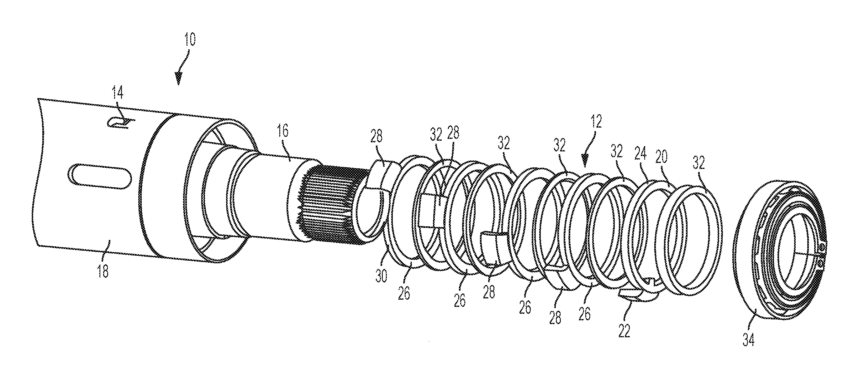
FIG. 1 is a perspective, partially disassembled view of a rotation control assembly for a steering column;
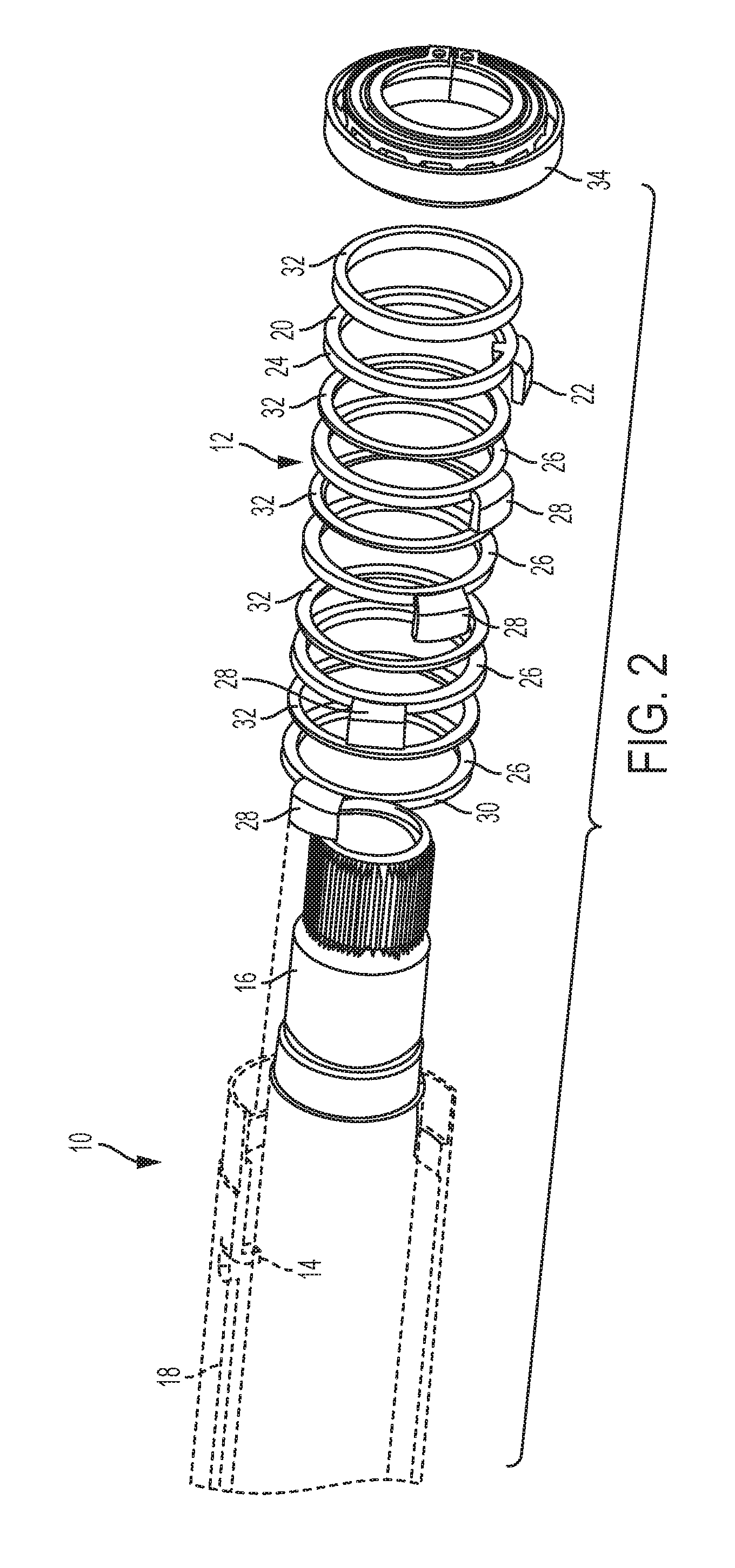
FIG. 2 is a perspective, cross-sectional, partially disassembled view of the rotation control assembly;
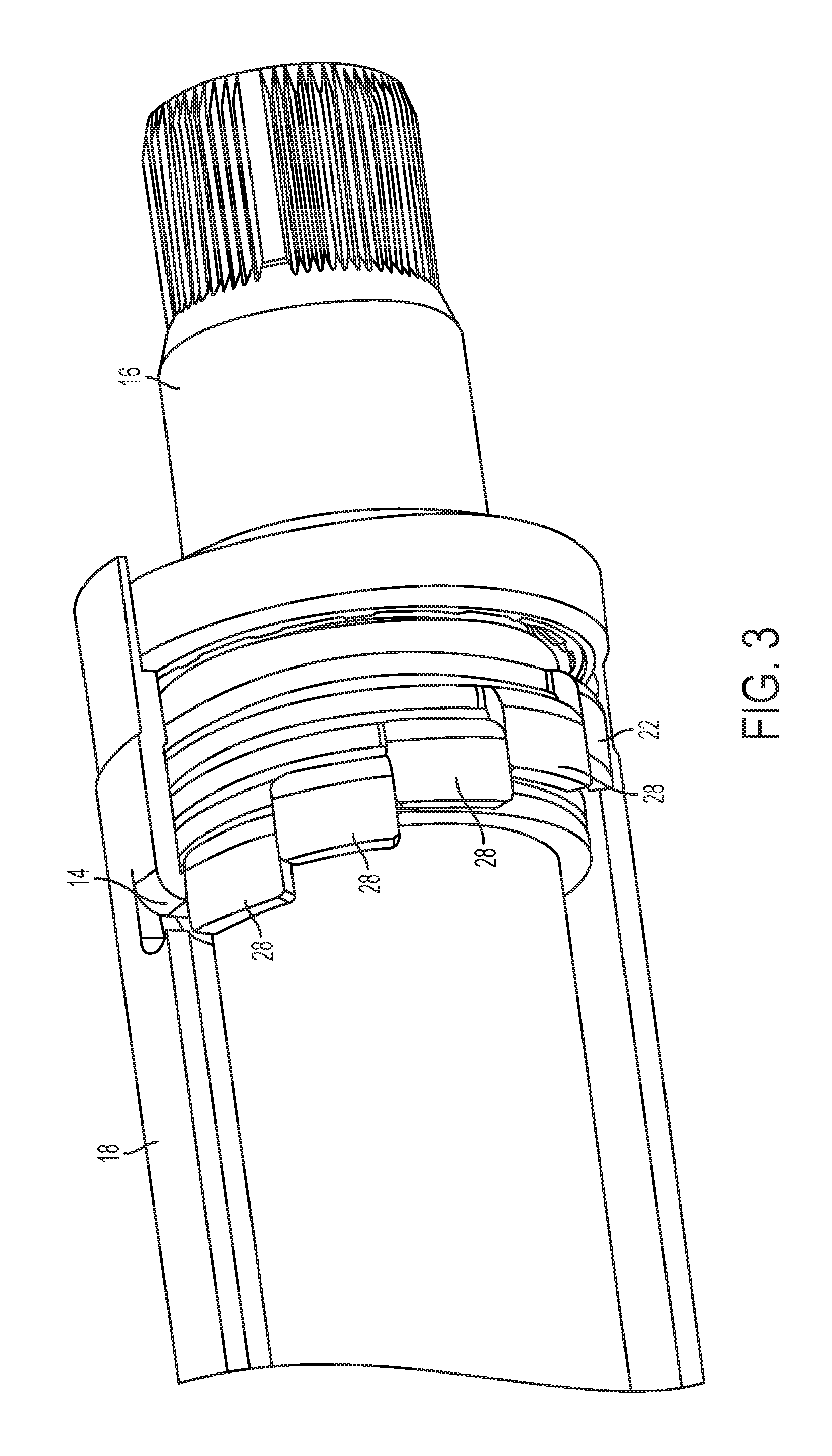
FIG. 3 is a perspective view of the rotation control assembly in a fully rotated position;
FIG. 4 is an end view of the rotation control assembly;
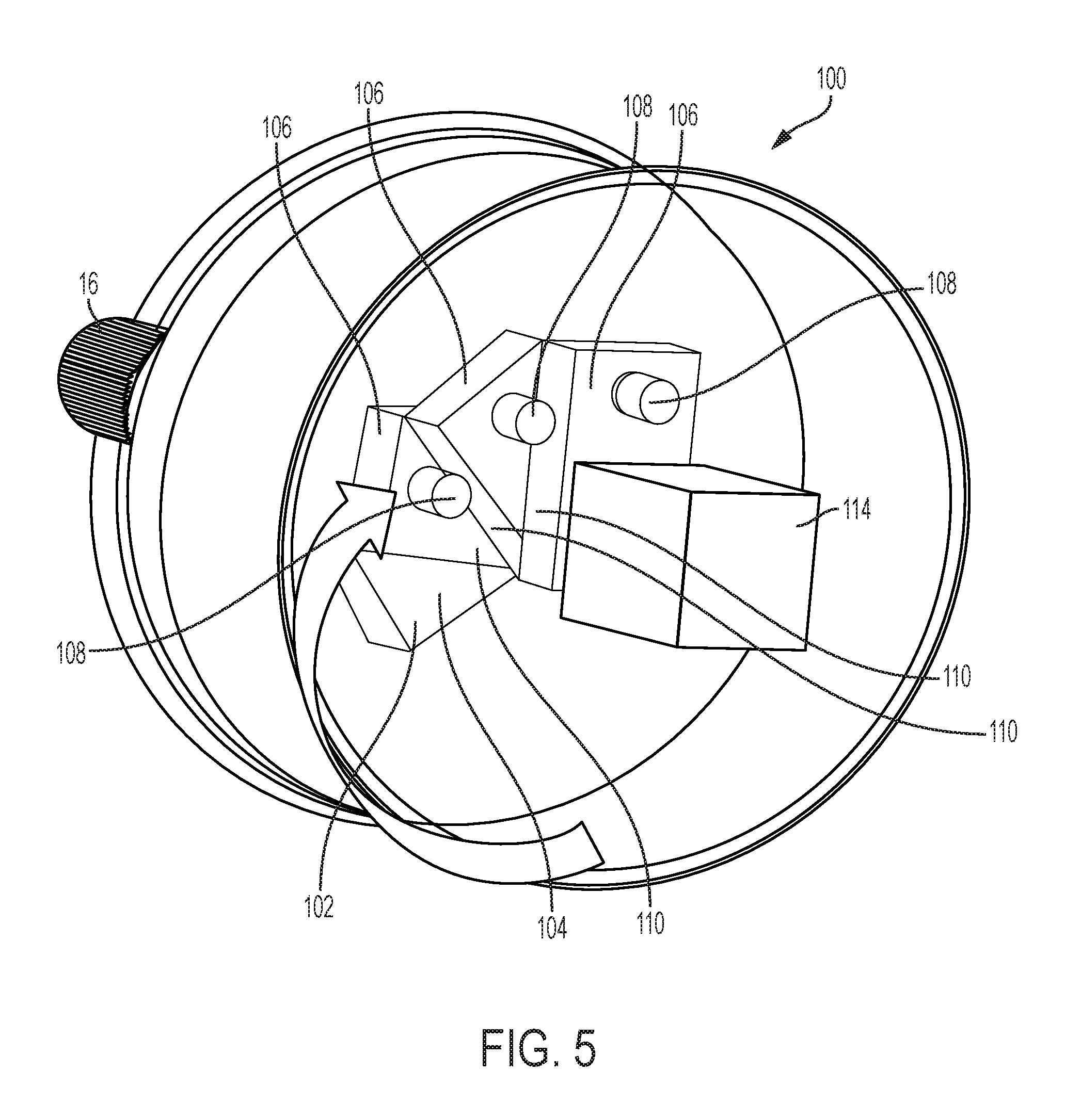
FIG. 5 is a perspective view of the rotation control assembly according to another aspect of the disclosure; and
FIG. 6 is a schematic view of the rotation control assembly according to yet another aspect of the disclosure.
DETAILED DESCRIPTION
Referring now to the Figures, where embodiments will be described, without limiting same, FIGS. 1-4 illustrate a steering column assembly generally referenced with numeral 10. The steering column assembly 10 may be employed on various types of vehicles. In some embodiments, the steering column assembly 10 is employed in an automobile and is a steering column that may be mechanically disconnected from a steering gear (not shown). For example, a steer-by-wire steering system may benefit from the embodiments described herein. In other embodiments, the steering column is part of a mechanical steering system having an I-shaft decoupling device.
In some situations, a steering wheel (not shown) operatively coupled to the steering column assembly 10 is easy to rotate. It may be possible to rotate the wheel beyond the wiring limits of a supplemental inflatable restraint (SIR) coil, thus severing the wire and making the vehicle non-functional or unsafe to drive. To address this issue, a rotation control assembly 12 is provided. The rotation control assembly 12 limits the angular rotation of the steering column assembly 10 by providing an end stop 14 that mechanically stops the angular travel of the steering column assembly 10.
The steering column assembly 10 includes a steering shaft 16 that rotates upon input from a user via rotation of the steering wheel. The steering shaft 16 is disposed radially inward of, and rotates within, a column jacket 18 that remains rotationally stationary, relative to the steering shaft 16. The end stop 14 that provides a hard stop for rotational travel of the steering shaft 16 is operatively coupled to, or integrally formed with, the column jacket 18 and extends radially inwardly therefrom. Alternatively, the end stop 14 may be operatively coupled to, or integrally formed with, a different steering column housing structure.
A fixed plate 20 surrounds at least a portion of the steering shaft 16 and is operatively coupled to, or integrally formed with, the steering shaft 16 in a manner that allows the fixed plate 20 to rotate with the steering shaft 16. In the illustrated embodiment, the fixed plate 20 is a cylindrical ring that extends completely around the steering shaft 16, but it is to be appreciated that alternative shapes may be utilized in some embodiments. Extending from the fixed plate 20 is a driving tab 22. In some embodiments, the driving tab 22 extends radially outward from a radially outer surface 24 of the fixed plate 20. Additionally, the driving tab 22 extends from the fixed plate 20 in an axial direction that facilitates engagement of the driving tab 22 with a tab of an adjacent plate, as described in detail below.
At least one rotating plate 26 surrounds the steering shaft 16, but is free to rotate relative to the steering shaft 16, unlike the fixed plate 20. As with the fixed plate 20, the rotating plate(s) 26 may be cylindrical rings that extend completely around the steering shaft 16, but it is to be appreciated that alternative shapes may be utilized in some embodiments. As shown in the illustrated embodiments, a plurality of rotating plates may be employed. In particular, the illustrated embodiments disclose four rotating plates, but the number of rotating plates may be modified to adjust the angular rotation limit of the steering shaft 16, as will be appreciated from the description herein. Regardless of the number of rotating plates 26, each rotating plate 26 includes a driven tab 28 extending therefrom. In some embodiments, the driven tab 28 extends radially outward from a radially outer surface 30 of the rotating plate 26. Additionally, the driven tab 28 extends from the rotating plate 26 in an axial direction that facilitates engagement of the driven tab 28 with a tab of an adjacent plate or the end stop 14.
As shown, a spacer plate 32 may be provided between adjacent rotating plates 26 and/or between a rotating plate 26 and the fixed plate 20. The spacer plate(s) 32 are cylindrical rings in the illustrated embodiment and surround the steering shaft 16. The spacer plate 32 is free to rotate relative to the steering shaft 16 and may be easily removed in an axial direction to allow adjustment of the number of rotating plates 26 included in the assembly. A shaft bearing 34 axially constrains the rotating plate(s) 26, the fixed plate 20 and the spacer plate(s) 32 and surrounds the steering shaft 16. It is to be appreciated that other axial retention components may be employed to axially constrain the rotating plate(s) 26, the fixed plate 20 and the spacer plate(s) 32.
In operation, the fixed plate 20 rotates in response to rotation of the steering shaft 16. This is due to engagement of the driving tab 22 with a keyway defined by the steering shaft 16 in some embodiments. In other embodiments, the fixed plate 20 is coupled to the steering shaft 16 in a manner that produces simultaneous rotation of the steering shaft 16 and the fixed plate 20, such as a welded securement or the like. Rotation of the fixed plate 20 results in rotation of the driving tab 22 until engagement with the driven tab 28 of an adjacent rotating plate 26 occurs. Further rotation results in rotation of the driving tab 22 and the driven tab 28 until engagement of the driven tab 28 engages an adjacent driven tab 28. This continues until a driven tab 28 of the rotating plate 26 located axially closest to the end stop 14 occurs. Engagement of the driven tab 28 closest to the end stop 14 results in a hard stop of angular movement by the steering shaft 16, thus avoiding undesirable consequences of over-rotation of the steering shaft 16.
Referring now to FIG. 5, another embodiment of the rotation control assembly is illustrated and referenced with numeral 100. The rotation control assembly 100 includes a fixed plate 102 that is operatively coupled to, or integrally formed with, the steering shaft 16 in a manner that allows the fixed plate 102 to rotate with the steering shaft 16. A fixed plate pin 104 extending perpendicularly, or substantially perpendicularly, from the fixed plate 102 is provided. At least one rotating plate 106 surrounds the steering shaft 16, but is free to rotate relative to the steering shaft 16, unlike the fixed plate 102. As shown, a plurality of rotating plates 106 may be employed. As is the case with the embodiment of FIGS. 1-4, the number of rotating plates may be modified to adjust the angular rotation limit of the steering shaft 16. In each embodiment, the number of rotating plates determines the angular degree of rotational travel of the steering shaft 16. Each of the rotating plates 106 include a rotating plate pin 108 that extends perpendicularly, or substantially perpendicularly, from the rotating plate 106.
In operation, the fixed plate 102 rotates in response to rotation of the steering shaft 16. Rotation of the fixed plate 102 results in rotation of the fixed plate pin 104 until engagement with an engagement surface 110 of an adjacent rotating plate 106 occurs. Further rotation results in rotation of the fixed plate pin 104 and the rotating plate pin 108 until engagement of the rotating plate pin 108 engages an engagement surface 110 of an adjacent rotating plate 106. This continues until a rotating plate pin 108 of the rotating plate 106 located axially closest to the end stop 114 engages the end stop 114. Engagement of the rotating plate pin 108 closest to the end stop 114 results in a hard stop of angular movement by the steering shaft 16, thus avoiding undesirable consequences of over-rotation of the steering shaft 16.
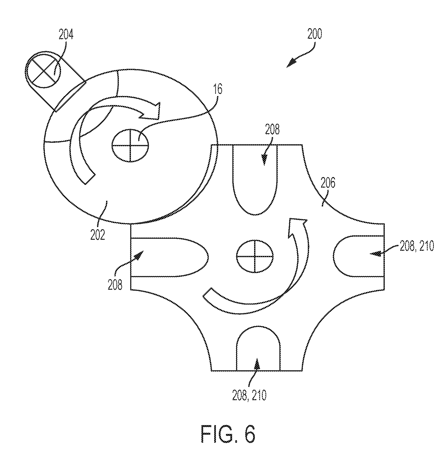
Referring now to FIG. 6, another embodiment of the rotation control assembly is illustrated and referenced with numeral 200. The rotation control assembly 200 includes a fixed plate 202 operatively coupled to, or integrally formed with, the steering shaft 16 in a manner that allows the fixed plate 202 to rotate with the steering shaft 16. A driving pin 204 extending perpendicularly, or substantially perpendicularly, from the fixed plate 202 is provided. A driven wheel 206 is disposed in proximity to the fixed plate 202 and rotates about an axis that is offset from, but parallel to, a rotation axis of the steering shaft 16 and the fixed plate 202. The driving pin 204 extends into one of a plurality of slots 208 of the driven wheel 206 to advance the driven wheel 206 by one step. This mechanism may be referred to as a Geneva gear that translates a continuous rotation of the steering shaft 16 and the fixed plate 202 into an intermittent rotary motion of the driven wheel 206. The fixed plate 202 may also have a raised blocking disc that locks the driven wheel 206 in position between steps.
In operation, as the steering shaft 16 rotates, the driving pin 204 engages one of the slots 208 of the driven wheel 206. As shown, some of the slots 208 extend radially deeper into the driven wheel 206 relative to other slots 208. The deeper slots allow continued rotation of the driven wheel 206 and consequently the fixed plate 202 and the steering shaft 16. The shallower slots do not allow continued rotation and are therefore considered end stops 210. The steering shaft 16 is free to reverse direction without binding or impulse locking.
While the invention has been described in detail in connection with only a limited number of embodiments, it should be readily understood that the invention is not limited to such disclosed embodiments. Rather, the invention can be modified to incorporate any number of variations, alterations, substitutions or equivalent arrangements not heretofore described, but which are commensurate with the spirit and scope of the invention. Additionally, while various embodiments of the invention have been described, it is to be understood that aspects of the invention may include only some of the described embodiments. Accordingly, the invention is not to be seen as limited by the foregoing description.
* * * * *
D00000
D00001
D00002
D00003
D00004
D00005
D00006
XML
uspto.report is an independent third-party trademark research tool that is not affiliated, endorsed, or sponsored by the United States Patent and Trademark Office (USPTO) or any other governmental organization. The information provided by uspto.report is based on publicly available data at the time of writing and is intended for informational purposes only.
While we strive to provide accurate and up-to-date information, we do not guarantee the accuracy, completeness, reliability, or suitability of the information displayed on this site. The use of this site is at your own risk. Any reliance you place on such information is therefore strictly at your own risk.
All official trademark data, including owner information, should be verified by visiting the official USPTO website at www.uspto.gov. This site is not intended to replace professional legal advice and should not be used as a substitute for consulting with a legal professional who is knowledgeable about trademark law.