Medical device delivery system and method
Euteneuer , et al.
U.S. patent number 10,226,325 [Application Number 14/883,170] was granted by the patent office on 2019-03-12 for medical device delivery system and method. This patent grant is currently assigned to Rotation Medical, Inc.. The grantee listed for this patent is Rotation Medical, Inc.. Invention is credited to Charles L. Euteneuer, Duane Frion, Rebecca McCarville, Nathaniel Zenz-Olson.


| United States Patent | 10,226,325 |
| Euteneuer , et al. | March 12, 2019 |
Medical device delivery system and method
Abstract
A tendon repair implant delivery system and methods incorporating a guide member having a temporary fixation member on or adjacent to the distal end. The point of fixation defines a target site for placement of the tendon repair implant which is subsequently affixed to the tendon.
| Inventors: | Euteneuer; Charles L. (St. Michael, MN), McCarville; Rebecca (Spring Park, MN), Frion; Duane (Brooklyn Center, MN), Zenz-Olson; Nathaniel (Blaine, MN) | ||||||||||
|---|---|---|---|---|---|---|---|---|---|---|---|
| Applicant: |
|
||||||||||
| Assignee: | Rotation Medical, Inc.
(Plymouth, MN) |
||||||||||
| Family ID: | 42738325 | ||||||||||
| Appl. No.: | 14/883,170 | ||||||||||
| Filed: | October 14, 2015 |
Prior Publication Data
| Document Identifier | Publication Date | |
|---|---|---|
| US 20160030157 A1 | Feb 4, 2016 | |
Related U.S. Patent Documents
| Application Number | Filing Date | Patent Number | Issue Date | ||
|---|---|---|---|---|---|
| 12729029 | Mar 22, 2010 | 9179910 | |||
| 61162234 | Mar 20, 2009 | ||||
| Current U.S. Class: | 1/1 |
| Current CPC Class: | A61B 17/064 (20130101); A61F 2/0805 (20130101); A61B 17/068 (20130101); A61B 17/00234 (20130101); A61B 17/1155 (20130101); A61B 17/07292 (20130101); A61B 2017/00349 (20130101); A61F 2/08 (20130101); A61B 2017/22047 (20130101); A61B 2017/22044 (20130101); A61B 2017/0647 (20130101); A61B 2017/22038 (20130101) |
| Current International Class: | A61F 2/08 (20060101); A61B 17/064 (20060101); A61B 17/068 (20060101); A61B 17/00 (20060101); A61B 17/072 (20060101); A61B 17/115 (20060101); A61B 17/22 (20060101) |
References Cited [Referenced By]
U.S. Patent Documents
| 511238 | December 1893 | Hieatzman |
| 765793 | July 1904 | Ruckel |
| 1728316 | September 1929 | Von Wachenfeldt |
| 1855546 | April 1932 | File |
| 1868100 | July 1932 | Goodstein |
| 1910688 | May 1933 | Goodstein |
| 1940351 | December 1933 | Howard |
| 2034785 | March 1936 | Wappler |
| 2075508 | March 1937 | Davidson |
| 2131321 | September 1938 | Hart |
| 2158242 | May 1939 | Maynard |
| 2199025 | April 1940 | Conn |
| 2201610 | May 1940 | Dawson, Jr. |
| 2254620 | September 1941 | Miller |
| 2277931 | March 1942 | Moe |
| 2283814 | May 1942 | La Place |
| 2316297 | April 1943 | Southerland et al. |
| 2421193 | May 1947 | Gardner |
| 2571813 | October 1951 | Austin |
| 2630316 | March 1953 | Foster |
| 2684070 | July 1954 | Kelsey |
| 2744251 | May 1956 | Vollmer |
| 2790341 | April 1957 | Keep et al. |
| 2817339 | December 1957 | Sullivan |
| 2825162 | March 1958 | Flood |
| 2881762 | April 1959 | Lowrie |
| 2910067 | October 1959 | White |
| 3068870 | December 1962 | Levin |
| 3077812 | February 1963 | Dietrich |
| 3103666 | September 1963 | Bone |
| 3123077 | March 1964 | Alcamo |
| 3209754 | October 1965 | Brown |
| 3221746 | December 1965 | Noble |
| 3470834 | October 1969 | Bone |
| 3527223 | September 1970 | Shein |
| 3570497 | March 1971 | Lemole |
| 3577837 | May 1971 | Bader, Jr. |
| 3579831 | May 1971 | Stevens et al. |
| 3643851 | February 1972 | Green et al. |
| 3687138 | August 1972 | Jarvik |
| 3716058 | February 1973 | Tanner, Jr. |
| 3717294 | February 1973 | Green |
| 3757629 | September 1973 | Schneider |
| 3777538 | December 1973 | Weatherly et al. |
| 3837555 | September 1974 | Green |
| 3845772 | November 1974 | Smith |
| 3875648 | April 1975 | Bone |
| 3960147 | June 1976 | Murray |
| 3976079 | August 1976 | Samuels et al. |
| 4014492 | March 1977 | Rothfuss |
| 4127227 | November 1978 | Green |
| 4259959 | April 1981 | Walker |
| 4263903 | April 1981 | Griggs |
| 4265226 | May 1981 | Cassimally |
| 4317451 | March 1982 | Cerwin et al. |
| 4400833 | August 1983 | Kurland |
| 4422567 | December 1983 | Haynes |
| 4454875 | June 1984 | Pratt et al. |
| 4480641 | November 1984 | Failla et al. |
| 4485816 | December 1984 | Krumme |
| 4526174 | July 1985 | Froehlich |
| 4549545 | October 1985 | Levy |
| 4570623 | February 1986 | Ellison et al. |
| 4595007 | June 1986 | Mericle |
| 4624254 | November 1986 | McGarry et al. |
| 4627437 | December 1986 | Bedi et al. |
| 4632100 | December 1986 | Somers et al. |
| 4635637 | January 1987 | Schreiber |
| 4669473 | June 1987 | Richards et al. |
| 4696300 | September 1987 | Anderson |
| 4719917 | January 1988 | Barrows et al. |
| 4738255 | April 1988 | Goble et al. |
| 4741330 | May 1988 | Hayhurst |
| 4762260 | August 1988 | Richards et al. |
| 4799495 | January 1989 | Hawkins et al. |
| 4809695 | March 1989 | Gwathmey et al. |
| 4851005 | July 1989 | Hunt et al. |
| 4858608 | August 1989 | McQuilkin |
| 4884572 | December 1989 | Bays et al. |
| 4887601 | December 1989 | Richards |
| 4924866 | May 1990 | Yoon |
| 4930674 | June 1990 | Barak |
| 4968315 | November 1990 | Gatturna |
| 4976715 | December 1990 | Bays et al. |
| 4994073 | February 1991 | Green |
| 4997436 | March 1991 | Oberlander |
| 5002563 | March 1991 | Pyka et al. |
| 5013316 | May 1991 | Goble et al. |
| 5015249 | May 1991 | Nakao et al. |
| 5037422 | August 1991 | Hayhurst et al. |
| 5041129 | August 1991 | Hayhurst et al. |
| 5046513 | September 1991 | Gatturna et al. |
| 5053047 | October 1991 | Yoon |
| 5059206 | October 1991 | Winters |
| 5062563 | November 1991 | Green et al. |
| 5100417 | March 1992 | Cerier et al. |
| 5102421 | April 1992 | Anspach, Jr. |
| 5116357 | May 1992 | Eberbach |
| 5122155 | June 1992 | Eberbach |
| 5123913 | June 1992 | Wilk et al. |
| RE34021 | August 1992 | Mueller et al. |
| 5141515 | August 1992 | Eberbach |
| 5141520 | August 1992 | Goble et al. |
| 5156609 | October 1992 | Nakao et al. |
| 5156616 | October 1992 | Meadows et al. |
| 5167665 | December 1992 | McKinney |
| 5171259 | December 1992 | Inoue |
| 5174295 | December 1992 | Christian et al. |
| 5174487 | December 1992 | Rothfuss et al. |
| 5176682 | January 1993 | Chow |
| 5176692 | January 1993 | Wilk et al. |
| 5203787 | April 1993 | Noblitt et al. |
| 5211650 | May 1993 | Noda |
| 5217472 | June 1993 | Green et al. |
| 5224946 | July 1993 | Hayhurst et al. |
| 5242457 | September 1993 | Akopov et al. |
| 5246441 | September 1993 | Ross et al. |
| 5251642 | October 1993 | Handlos |
| 5261914 | November 1993 | Warren |
| 5269753 | December 1993 | Wilk |
| 5269783 | December 1993 | Sander |
| 5282829 | February 1994 | Hermes |
| 5289963 | March 1994 | McGarry et al. |
| 5290217 | March 1994 | Campos |
| 5304187 | April 1994 | Green |
| 5333624 | August 1994 | Tovey |
| 5342396 | August 1994 | Cook |
| 5350400 | September 1994 | Esposito et al. |
| 5352229 | October 1994 | Goble et al. |
| 5354292 | October 1994 | Braeuer et al. |
| 5364408 | November 1994 | Gordon |
| 5366460 | November 1994 | Eberbach |
| 5370650 | December 1994 | Tovey et al. |
| 5372604 | December 1994 | Trott |
| 5380334 | January 1995 | Torrie et al. |
| 5383477 | January 1995 | DeMatteis |
| 5397332 | March 1995 | Kammerer et al. |
| 5403326 | April 1995 | Harrison et al. |
| 5405360 | April 1995 | Tovey |
| 5411522 | May 1995 | Trott |
| 5411523 | May 1995 | Goble |
| 5417691 | May 1995 | Hayhurst |
| 5417712 | May 1995 | Whittaker et al. |
| 5425490 | June 1995 | Goble et al. |
| 5441502 | August 1995 | Bartlett |
| 5441508 | August 1995 | Gazielly et al. |
| 5456720 | October 1995 | Schultz et al. |
| 5464403 | November 1995 | Kieturakis et al. |
| 5478354 | December 1995 | Tovey et al. |
| 5486197 | January 1996 | Le et al. |
| 5497933 | March 1996 | DeFonzo et al. |
| 5500000 | March 1996 | Feagin et al. |
| 5501695 | March 1996 | Anspach, Jr. et al. |
| 5503623 | April 1996 | Tilton, Jr. |
| 5505735 | April 1996 | Li |
| 5507754 | April 1996 | Green et al. |
| 5520700 | May 1996 | Beyar et al. |
| 5522817 | June 1996 | Sander et al. |
| 5545180 | August 1996 | Le et al. |
| 5560532 | October 1996 | DeFonzo et al. |
| 5562689 | October 1996 | Green et al. |
| 5569306 | October 1996 | Thal |
| 5582616 | December 1996 | Bolduc et al. |
| 5584835 | December 1996 | Greenfield |
| 5618314 | April 1997 | Harwin et al. |
| 5622257 | April 1997 | Deschenes et al. |
| 5628751 | May 1997 | Sander et al. |
| 5643319 | July 1997 | Green et al. |
| 5643321 | July 1997 | McDevitt |
| 5647874 | July 1997 | Hayhurst |
| 5649963 | July 1997 | McDevitt |
| 5662683 | September 1997 | Kay |
| 5667513 | September 1997 | Torrie et al. |
| 5674245 | October 1997 | Ilgen |
| 5681342 | October 1997 | Benchetrit |
| 5702215 | December 1997 | Li |
| 5713903 | February 1998 | Sander et al. |
| 5720753 | February 1998 | Sander et al. |
| 5725541 | March 1998 | Anspach, III et al. |
| 5741282 | April 1998 | Anspach, III et al. |
| 5766246 | June 1998 | Mulhauser et al. |
| 5782864 | July 1998 | Lizardi |
| 5797909 | August 1998 | Michelson |
| 5797931 | August 1998 | Bito et al. |
| 5797963 | August 1998 | McDevitt |
| 5807403 | September 1998 | Beyar et al. |
| 5830221 | November 1998 | Stein et al. |
| 5836961 | November 1998 | Kieturakis et al. |
| 5868762 | February 1999 | Cragg et al. |
| 5873891 | February 1999 | Sohn |
| 5885258 | March 1999 | Sachdeva et al. |
| 5885294 | March 1999 | Pedlick et al. |
| 5893856 | April 1999 | Jacob et al. |
| 5904696 | May 1999 | Rosenman |
| 5919184 | July 1999 | Tilton, Jr. |
| 5922026 | July 1999 | Chin |
| 5928244 | July 1999 | Tovey et al. |
| 5948000 | September 1999 | Larsen et al. |
| 5957939 | September 1999 | Heaven et al. |
| 5957953 | September 1999 | DiPoto et al. |
| 5968044 | October 1999 | Nicholson et al. |
| 5980557 | November 1999 | Iserin et al. |
| 5989265 | November 1999 | Bouquet De La Joliniere et al. |
| 5997552 | December 1999 | Person et al. |
| 6063088 | May 2000 | Winslow |
| 6156045 | December 2000 | Ulbrich et al. |
| 6179840 | January 2001 | Bowman |
| 6193731 | February 2001 | Oppelt et al. |
| 6193733 | February 2001 | Adams |
| 6245072 | June 2001 | Zdeblick et al. |
| 6302885 | October 2001 | Essiger |
| 6312442 | November 2001 | Kieturakis et al. |
| 6315789 | November 2001 | Cragg |
| 6318616 | November 2001 | Pasqualucci et al. |
| 6322563 | November 2001 | Cummings et al. |
| 6325805 | December 2001 | Ogilvie et al. |
| 6387113 | May 2002 | Hawkins et al. |
| 6391333 | May 2002 | Li et al. |
| 6413274 | July 2002 | Pedros |
| 6425900 | July 2002 | Knodel |
| 6436110 | August 2002 | Bowman et al. |
| 6447522 | September 2002 | Gambale et al. |
| 6447524 | September 2002 | Knodel et al. |
| 6478803 | November 2002 | Kapec et al. |
| 6482178 | November 2002 | Andrews et al. |
| 6482210 | November 2002 | Skiba et al. |
| 6506190 | January 2003 | Walshe |
| 6511499 | January 2003 | Schmieding et al. |
| 6517564 | February 2003 | Grafton et al. |
| 6524316 | February 2003 | Nicholson et al. |
| 6527795 | March 2003 | Lizardi |
| 6540769 | April 2003 | Miller, III |
| 6551333 | April 2003 | Kuhns et al. |
| 6554852 | April 2003 | Oberlander |
| 6569186 | May 2003 | Winters et al. |
| 6575976 | June 2003 | Grafton |
| 6599289 | July 2003 | Bojarski et al. |
| 6620185 | September 2003 | Harvie et al. |
| 6629988 | October 2003 | Weadock |
| 6638297 | October 2003 | Huitema |
| 6648893 | November 2003 | Dudasik |
| 6666872 | December 2003 | Barreiro et al. |
| 6673094 | January 2004 | McDevitt et al. |
| 6685728 | February 2004 | Sinnott et al. |
| 6692506 | February 2004 | Ory et al. |
| 6723099 | April 2004 | Goshert |
| 6726704 | April 2004 | Loshakove et al. |
| 6726705 | April 2004 | Peterson et al. |
| 6740100 | May 2004 | Demopulos et al. |
| 6746472 | June 2004 | Frazier et al. |
| 6764500 | July 2004 | Muijs Van De Moer et al. |
| 6770073 | August 2004 | McDevitt et al. |
| 6779701 | August 2004 | Bailly et al. |
| 6800081 | October 2004 | Parodi |
| 6835206 | December 2004 | Jackson |
| 6849078 | February 2005 | Durgin et al. |
| 6887259 | May 2005 | Lizardi |
| 6926723 | August 2005 | Mulhauser et al. |
| 6932834 | August 2005 | Lizardi et al. |
| 6939365 | September 2005 | Fogarty et al. |
| 6946003 | September 2005 | Wolowacz et al. |
| 6949117 | September 2005 | Gambale et al. |
| 6964685 | November 2005 | Murray et al. |
| 6966916 | November 2005 | Kumar |
| 6972027 | December 2005 | Fallin et al. |
| 6984241 | January 2006 | Lubbers et al. |
| 6991597 | January 2006 | Gellman et al. |
| 7008435 | March 2006 | Cummins |
| 7021316 | April 2006 | Leiboff |
| 7025772 | April 2006 | Gellman et al. |
| 7033379 | April 2006 | Peterson |
| 7037324 | May 2006 | Martinek |
| 7048171 | May 2006 | Thornton et al. |
| 7063711 | June 2006 | Loshakove et al. |
| 7083638 | August 2006 | Foerster |
| 7087064 | August 2006 | Hyde |
| 7112214 | September 2006 | Peterson et al. |
| 7118581 | October 2006 | Friden |
| 7144413 | December 2006 | Wilford et al. |
| 7144414 | December 2006 | Harvie et al. |
| 7150750 | December 2006 | Damarati |
| 7153314 | December 2006 | Laufer et al. |
| 7160314 | January 2007 | Sgro et al. |
| 7160326 | January 2007 | Ball |
| 7163551 | January 2007 | Anthony et al. |
| 7163563 | January 2007 | Schwartz et al. |
| 7169157 | January 2007 | Kayan |
| 7189251 | March 2007 | Kay |
| 7201754 | April 2007 | Stewart et al. |
| 7214232 | May 2007 | Bowman et al. |
| 7226469 | June 2007 | Benavitz et al. |
| 7229452 | June 2007 | Kayan |
| 7247164 | July 2007 | Ritchart et al. |
| 7303577 | December 2007 | Dean |
| 7309337 | December 2007 | Colleran et al. |
| 7320692 | January 2008 | Bender et al. |
| 7320701 | January 2008 | Haut et al. |
| 7322935 | January 2008 | Palmer et al. |
| 7326231 | February 2008 | Phillips et al. |
| 7343920 | March 2008 | Toby et al. |
| 7368124 | May 2008 | Chun et al. |
| 7377934 | May 2008 | Lin et al. |
| 7381213 | June 2008 | Lizardi |
| 7390329 | June 2008 | Westra et al. |
| 7399304 | July 2008 | Gambale et al. |
| 7404824 | July 2008 | Webler et al. |
| 7416554 | August 2008 | Lam et al. |
| 7452368 | November 2008 | Liberatore et al. |
| 7460913 | December 2008 | Kuzma et al. |
| 7463933 | December 2008 | Wahlstrom et al. |
| 7465308 | December 2008 | Sikora et al. |
| 7481832 | January 2009 | Meridew et al. |
| 7485124 | February 2009 | Kuhns et al. |
| 7497854 | March 2009 | Gill et al. |
| 7500972 | March 2009 | Voegele et al. |
| 7500980 | March 2009 | Gill et al. |
| 7500983 | March 2009 | Kaiser et al. |
| 7503474 | March 2009 | Hillstead et al. |
| 7506791 | March 2009 | Omaits et al. |
| 7559941 | July 2009 | Zannis et al. |
| 7572276 | August 2009 | Lim et al. |
| 7585311 | September 2009 | Green et al. |
| 7766208 | August 2010 | Epperly et al. |
| 7771440 | August 2010 | Ortiz et al. |
| 7776057 | August 2010 | Laufer et al. |
| 7780685 | August 2010 | Hunt et al. |
| 7785255 | August 2010 | Malkani |
| 7807192 | October 2010 | Li et al. |
| 7819880 | October 2010 | Zannis et al. |
| 7918879 | April 2011 | Yeung et al. |
| 8114101 | February 2012 | Criscuolo et al. |
| 8197837 | June 2012 | Jamiolkowski et al. |
| 8668718 | March 2014 | Euteneuer et al. |
| 8763878 | July 2014 | Euteneuer et al. |
| 8821536 | September 2014 | Euteneuer et al. |
| 9179910 | November 2015 | Euteneuer et al. |
| 9179961 | November 2015 | Euteneuer et al. |
| 2002/0077687 | June 2002 | Ahn |
| 2002/0090725 | July 2002 | Simpson et al. |
| 2002/0123767 | September 2002 | Prestel |
| 2002/0165559 | November 2002 | Grant et al. |
| 2003/0073979 | April 2003 | Naimark |
| 2003/0212456 | November 2003 | Lipchitz et al. |
| 2004/0059416 | March 2004 | Murray et al. |
| 2004/0073219 | April 2004 | Skiba et al. |
| 2004/0138705 | July 2004 | Heino et al. |
| 2004/0167519 | August 2004 | Weiner et al. |
| 2005/0015021 | January 2005 | Shiber |
| 2005/0049618 | March 2005 | Masuda et al. |
| 2005/0051597 | March 2005 | Toledano |
| 2005/0059996 | March 2005 | Bauman et al. |
| 2005/0060033 | March 2005 | Vacanti et al. |
| 2005/0107807 | May 2005 | Nakao |
| 2005/0113736 | May 2005 | Orr et al. |
| 2005/0171569 | August 2005 | Girard et al. |
| 2005/0187576 | August 2005 | Whitman et al. |
| 2005/0240222 | October 2005 | Shipp |
| 2005/0274768 | December 2005 | Cummins et al. |
| 2006/0074423 | April 2006 | Alleyne et al. |
| 2006/0178743 | August 2006 | Carter |
| 2006/0235442 | October 2006 | Huitema |
| 2006/0293760 | December 2006 | DeDeyne |
| 2007/0078477 | April 2007 | Heneveld, Sr. et al. |
| 2007/0083236 | April 2007 | Sikora et al. |
| 2007/0112361 | May 2007 | Schonholz et al. |
| 2007/0179531 | August 2007 | Thornes |
| 2007/0185506 | August 2007 | Jackson |
| 2007/0190108 | August 2007 | Datta et al. |
| 2007/0219558 | September 2007 | Deutsch |
| 2007/0270804 | November 2007 | Chudik |
| 2007/0288023 | December 2007 | Pellegrino et al. |
| 2008/0027470 | January 2008 | Hart et al. |
| 2008/0051888 | February 2008 | Ratcliffe et al. |
| 2008/0065153 | March 2008 | Allard et al. |
| 2008/0090936 | April 2008 | Fujimura et al. |
| 2008/0125869 | May 2008 | Paz et al. |
| 2008/0135600 | June 2008 | Hiranuma et al. |
| 2008/0173691 | July 2008 | Mas et al. |
| 2008/0188874 | August 2008 | Henderson |
| 2008/0188936 | August 2008 | Ball et al. |
| 2008/0195119 | August 2008 | Ferree |
| 2008/0200949 | August 2008 | Hiles et al. |
| 2008/0241213 | October 2008 | Chun et al. |
| 2008/0272173 | November 2008 | Coleman et al. |
| 2008/0306408 | December 2008 | Lo |
| 2009/0001122 | January 2009 | Prommersberger et al. |
| 2009/0012521 | January 2009 | Axelson, Jr. et al. |
| 2009/0030434 | January 2009 | Paz et al. |
| 2009/0069806 | March 2009 | De La Mora Levy et al. |
| 2009/0076541 | March 2009 | Chin et al. |
| 2009/0105535 | April 2009 | Green et al. |
| 2009/0112085 | April 2009 | Eby |
| 2009/0134198 | May 2009 | Knodel et al. |
| 2009/0156986 | June 2009 | Trenhaile |
| 2009/0156997 | June 2009 | Trenhaile |
| 2009/0182245 | July 2009 | Zambelli |
| 2009/0242609 | October 2009 | Kanner |
| 2010/0145367 | June 2010 | Ratcliffe |
| 2010/0147922 | June 2010 | Olson |
| 2010/0163598 | July 2010 | Belzer |
| 2010/0191332 | July 2010 | Euteneuer et al. |
| 2010/0241227 | September 2010 | Euteneuer et al. |
| 2010/0249801 | September 2010 | Sengun et al. |
| 2010/0256675 | October 2010 | Romans |
| 2010/0274278 | October 2010 | Fleenor et al. |
| 2010/0292715 | November 2010 | Nering et al. |
| 2010/0292791 | November 2010 | Lu et al. |
| 2010/0327042 | December 2010 | Amid et al. |
| 2011/0011917 | January 2011 | Loulmet |
| 2011/0034942 | February 2011 | Levin et al. |
| 2011/0040310 | February 2011 | Levin et al. |
| 2011/0040311 | February 2011 | Levin et al. |
| 2011/0066166 | March 2011 | Levin et al. |
| 2011/0106154 | May 2011 | DiMatteo et al. |
| 2011/0114700 | May 2011 | Baxter, III et al. |
| 2011/0224702 | September 2011 | Van Kampen et al. |
| 2012/0160893 | June 2012 | Harris et al. |
| 2012/0193391 | August 2012 | Michler et al. |
| 2012/0209401 | August 2012 | Euteneuer et al. |
| 2012/0211543 | August 2012 | Euteneuer |
| 2012/0248171 | October 2012 | Bailly et al. |
| 2012/0316608 | December 2012 | Foley |
| 2013/0153627 | June 2013 | Euteneuer et al. |
| 2013/0153628 | June 2013 | Euteneuer |
| 2013/0158554 | June 2013 | Euteneuer et al. |
| 2013/0158587 | June 2013 | Euteneuer et al. |
| 2013/0158661 | June 2013 | Euteneuer et al. |
| 2013/0172920 | July 2013 | Euteneuer et al. |
| 2013/0172997 | July 2013 | Euteneuer et al. |
| 2013/0184716 | July 2013 | Euteneuer et al. |
| 2013/0240598 | September 2013 | Euteneuer et al. |
| 2013/0245627 | September 2013 | Euteneuer et al. |
| 2013/0245682 | September 2013 | Euteneuer et al. |
| 2013/0245683 | September 2013 | Euteneuer et al. |
| 2013/0245706 | September 2013 | Euteneuer et al. |
| 2013/0245707 | September 2013 | Euteneuer et al. |
| 2013/0245762 | September 2013 | Van Kampen et al. |
| 2013/0245774 | September 2013 | Euteneuer et al. |
| 2390508 | May 2001 | CA | |||
| 0142225 | May 1985 | EP | |||
| 0298400 | Jan 1989 | EP | |||
| 0390613 | Oct 1990 | EP | |||
| 0543499 | May 1993 | EP | |||
| 0548998 | Jun 1993 | EP | |||
| 0557963 | Sep 1993 | EP | |||
| 0589306 | Mar 1994 | EP | |||
| 0908152 | Apr 1999 | EP | |||
| 1491157 | Dec 2004 | EP | |||
| 1559379 | Aug 2005 | EP | |||
| 2030576 | Mar 2009 | EP | |||
| 2154688 | Sep 1985 | GB | |||
| 2397240 | Jul 2007 | GB | |||
| 58188442 | Nov 1983 | JP | |||
| 2005506122 | Mar 2005 | JP | |||
| 2006515774 | Jun 2006 | JP | |||
| 85005025 | Nov 1985 | WO | |||
| 0176456 | Oct 2001 | WO | |||
| 200234140 | May 2002 | WO | |||
| 2003105670 | Dec 2003 | WO | |||
| 2004000138 | Dec 2003 | WO | |||
| 2004093690 | Nov 2004 | WO | |||
| 2005016389 | Feb 2005 | WO | |||
| 2006086679 | Aug 2006 | WO | |||
| 2007014910 | Feb 2007 | WO | |||
| 2007030676 | Mar 2007 | WO | |||
| 2007078978 | Jul 2007 | WO | |||
| 2007082088 | Jul 2007 | WO | |||
| 2008111073 | Sep 2008 | WO | |||
| 2008111078 | Sep 2008 | WO | |||
| 2008139473 | Nov 2008 | WO | |||
| 2009079211 | Jun 2009 | WO | |||
| 2009143331 | Nov 2009 | WO | |||
| 2011095890 | Aug 2011 | WO | |||
Other References
|
Abbaroodle et al., "Rotator Cuff Tear," Wikipedia, pp. 1-14, Web. Dec. 6, 2012. cited by applicant . Alexander et al., "Ligament and Tendon Repair with an Absorbable Polymer-Coated Carbon Fiber Stent," Bulletin of the Hospital; for Joint Diseases Orthopaedic Institute, vol. 46(2):155-173, 1986. cited by applicant . Bahler et al., "Trabecular Bypass Stents Decrease Intraocular Pressure in Cultured Human Anterior Segments," American Journal of Opthalmology, vol. 138(6):988-994, 2004. cited by applicant . Chamay et al., "Digital Contracture Deformity after Implantation of a Silicone Prosthesis: Light and Electron Microscopic Study," The Journal of Hand Surgery, vol. 3(3):266-270, 1978. cited by applicant . D'Ermo et al., "Our Results with the Operation of ab externo Trabeculotomym" Ophthalmologica, vol. 168, 347-355, 1971. cited by applicant . France et al., "Biomechanical Evaluation of Rotator Cuff Fixation Methods," The American Journal of Sports Medicine, vol. 17(2): 176-181,1989. cited by applicant . Goodship et al., "An Assessment of Filamentous Carbon Fibre for the Treatment of Tendon Injury in the Horse," The Veterinary Record, vol. 106, 217-221, 1980. cited by applicant . Hunter et al., "Flexor-Tendon Reconstruction in Severely Damaged Hands," The Journal of Bone and Joint Surgery (American Volume), vol. 53-A(5):329-358, 1971. cited by applicant . Johnstone et al., "Microsurgery of Schlemm's Canal and the Human Aqueous Outflow System," American Journal Opthalmology, vol. 76(6):906-917, 1973. cited by applicant . Kowalsky et al., "Evaluation of Suture Abrasion Against Rotator Cuff Tendon and Proximal Humerus Bone," Arthroscopy: The Journal of Arthroscopic and Related Surgery, vol. 24(3): 329-334, 2008. cited by applicant . Lee et al., "Aqueous-venous Shunt and Intraocular Pressure. Preliminary Report of Animal Studies," Investigative Opthalmology, vol. 5(1):59-64, 1966. cited by applicant . Maepea et al., "The Pressures in the Episcleral Veins, Schlemm's Canal and the Trabecular Meshwork in Monkeys: Effects of Changes in Intraocular Pressure," Exp. Eye Res., vol. 49, 645-663, 1989. cited by applicant . Nicolle et al., "A Silastic Tendon Prosthesis as an adjunct to Flexor Tendon Grafting: An Experimental and Clinical Evaluation," British Journal of Plastic Surgery, vol. 22, Issues 3-4, 224-236, 1969. cited by applicant . Rubin et al., "The Use of Acellular Biologic Tissue Patches in Foot and Ankle Surgery," Clinics in Podiatric Medicine and Surgery, vol. 22, 533-552, 2005. cited by applicant . Schultz, "Canaloplasty Procedure Shows Promise for Open-angle Glaucoma in European Study," Ocular Surgery News, pp. 34-35, 2007. cited by applicant . Spiegel et al., "Schlemm's Canal Implant: A New Method of Lower Intraocular Pressure in Patients with POAG?" Opthalmic Surgery and Lasers, vol. 30(6): 492-494, 1999. cited by applicant . Stetson et al., "Arthroscopic Treatment of Partial Rotator Cuff Tears," Operative Techniques in Sports Medicine, vol. 12, Issue 2, pp. 135-148, 2004. cited by applicant . Valdez et al., "Repair of Digital Flexor Tendon Lacerations in the Horse, Using Carbon Fiber Implants," JAVMA, vol. 177(5): 427-435, 1980. cited by applicant. |
Primary Examiner: Woznicki; Jacqueline
Attorney, Agent or Firm: Seager, Tufte & Wickhem LLP
Parent Case Text
CROSS REFERENCE TO RELATED APPLICATIONS
This application is a continuation of U.S. application Ser. No. 12/729,029 filed on Mar. 22, 2010, which claims benefit to U.S. Provisional Patent Application No. 61/162,234, filed on Mar. 20, 2009, which is related to U.S. patent application Ser. No. 12/684,774, filed on Jan. 8, 2010. The disclosures of each of which are herein incorporated by reference in their entirety.
Claims
What is claimed is:
1. An implant delivery system comprising: a sheath member having a distal end and a proximal end, the sheath member extending along a longitudinal axis; a locating guide having a proximal end and a distal end and disposed at least partially within the sheath member; a tendon repair implant disposed within the sheath member, the tendon repair implant having a first side and a second side opposite the first side: and a support disposed at least partially within the sheath member; wherein the support frame assumes a compact configuration when disposed within the sheath member and assumes an expanded configuration when uncovered by the sheath member, wherein the support in the expanded configuration is configured to overlay and contact only the first side of the tendon repair implant to press the tendon repair implant against tissue, wherein the locating guide further comprises a temporary fixation mechanism disposed proximate the distal end of the locating guide, and wherein, when the support is in the expanded configuration, a distal portion of the locating guide extends through the tendon repair implant from the first side to the second side, such that the temporary fixation mechanism is positioned distal of the tendon repair implant to penetrate tissue.
2. The implant delivery system of claim 1, wherein in the expanded configuration the support lies in a plane parallel to the longitudinal axis.
3. The implant delivery system of claim 1, wherein the sheath member is retractable relative to the support to uncover the support.
4. The implant delivery system of claim 1, wherein the tendon repair implant is slidable relative to the locating guide.
5. An implant delivery system comprising: a sheath member having a distal end and a proximal end; a locating guide having a proximal end and a distal end and disposed at least partially within the sheath member; a tendon repair implant disposed within the sheath member, the tendon repair implant having a first side and a second side opposite the first side; and a support disposed at least partially within the sheath member, wherein at least a portion of the support assumes a compact configuration within the sheath member, wherein when the portion of the support in the compact configuration is uncovered by the sheath member, the support expands from the compact configuration to an expanded configuration, wherein the support in the expanded configuration is configured to overlay the tendon repair implant and contact only the first side of the tendon repair implant to press the tendon repair implant against tissue, wherein the locating guide comprises a temporary fixation feature disposed adjacent the locating guide distal end, the temporary fixation feature extends through the tendon repair implant from the first side to the second side such that the temporary fixation feature is positioned distal of the tendon implant to penetrate tissue when the support is in the expanded configuration.
6. The implant delivery system of claim 5, wherein the support resides within a support sheath, wherein the support sheath is disposed within the sheath member, and wherein the support assumes the expanded configuration when uncovered by both the sheath member and the support sheath.
7. The implant delivery system of claim 5, wherein the locating guide extends through a portion of the tendon repair implant.
8. The implant delivery system of claim 5, further comprising an implant push rod to advance the tendon repair implant distally through the sheath member.
9. The implant delivery system of claim 5, wherein the tendon repair implant is self-expanding.
Description
INCORPORATION BY REFERENCE
All publications and patent applications mentioned in this specification are herein incorporated by reference to the same extent as if each individual publication or patent application was specifically and individually indicated to be incorporated by reference.
FIELD OF THE INVENTION
The present invention relates generally to orthopedic medicine and surgery. More particularly, the present invention relates to methods and apparatus for delivery and fixation of medical devices, such as for treating articulating joints.
BACKGROUND OF THE INVENTION
The shoulder joint is found where the head of the humerus mates with a shallow depression in the scapula. The movement of the humerus relative to the scapula is controlled by a number of muscles including: the deltoid, the supraspinatus, the infraspinatus, the subscapularis, and the teres minor. Various patterns of activating these muscles create various rotational moments because the shoulder joint has no fixed axis. The tendons linking the supraspinatus, the infraspinatus, the subscapularis, and the teres minor to the humerus are typically referred to as the rotator cuff tendons. Some studies suggest that 85% of people over the age of 65 have some degree of rotator cuff damage. This damage may include thinning, fraying, and/or tearing of the rotator cuff tendons. Various factors may contribute to this rotator cuff damage. These factors include aging, overuse of the shoulder, and wearing of the tendons. Wearing of the tendons can occur, for example, when the rotator cuff tendons rub against a bone (e.g., the acromium of the scapula).
SUMMARY OF THE INVENTION
In accordance with various aspects of the present disclosure, a tendon repair implant and delivery system is provided that, in some embodiments includes a guide member having a temporary fixation member disposed adjacent to or on a distal end thereof. In some embodiments, the temporary fixation member is disposed proximate the distal end of the guide member. The guide member can be arthroscopically inserted to an implantation site and temporarily fixed at the site. A tendon repair implant including a sheet-like structure disposed in a collapsed configuration can be disposed over the guide member for slidable positioning to a target site.
The tendon repair implant can be pleat folded to the collapsed configuration and upon delivery to the target site assume an expanded shape.
The temporary fixation member can include a projection for piercing a tendon to provide a fixed target site for delivery of the tendon repair implant. The fixation member can also include a retractable barb for temporarily fixing the fixation member to the tendon. Alternatively, the temporary fixation member can include a threaded projection.
In some embodiments, the system of the present invention can include a tendon repair implant delivery tool which assists in placing and affixing the tendon repair implant to the tendon. The tendon repair implant delivery tool can include a support ring tube defining a lumen within which is disposed an anchor. Further, a pull wire is disposed within the lumen defined by the support ring tube and extends through a channel defined by the anchor. The pull wire can include a flange adjacent a proximal end of the anchor with the flange having a diameter greater than a width of the channel such that force applied to the pull wire causes the flange to deploy the anchor into adjacent tissue.
In some embodiments, the present invention also includes a method for positioning a tendon repair implant to overlay at least a portion of a supraspinatus tendon in the shoulder of a patient. The method includes providing an implant delivery device including a guide member having a temporary fixation member thereon which is then positioned with a distal portion of the guide member adjacent a bursal side of the supraspinatus tendon at a target site. The guide member is temporarily fixed to target site with the temporary fixation member. The tendon repair implant is advanced over the guide member for delivering the tendon repair implant to the target site and fixed to the supraspinatus tendon. The guide member is then removed from the target site. In some exemplary methods, the distal portion of the guide member is inserted from the front or back of the patient to a position adjacent the supraspinatus tendon. The guide member may be oriented so that it is generally parallel or tangent to an outer surface of the supraspinatus tendon.
BRIEF DESCRIPTION OF THE DRAWINGS
FIG. 1A is an isometric view of a shoulder including a humerus and a scapula.
FIG. 1B and FIG. 1C are cross-sectional views illustrating two states of an exemplary temporary fixation mechanism.
FIG. 2 is a plan view of an exemplary tendon repair implant delivery system.
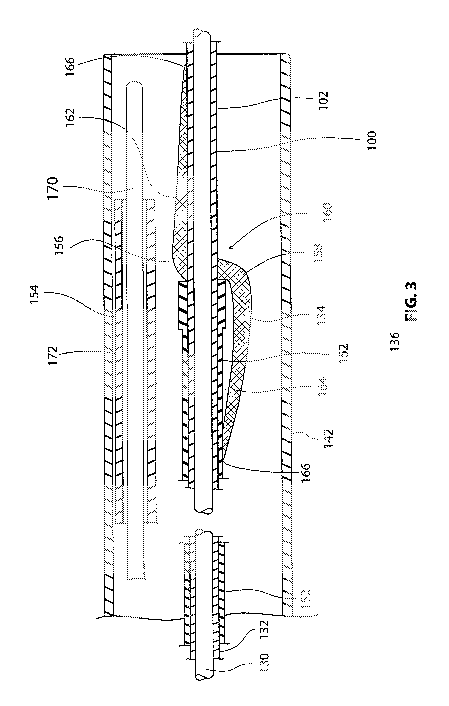
FIG. 3 is a cross-sectional view illustrating a distal portion of an exemplary tendon repair implant delivery system.
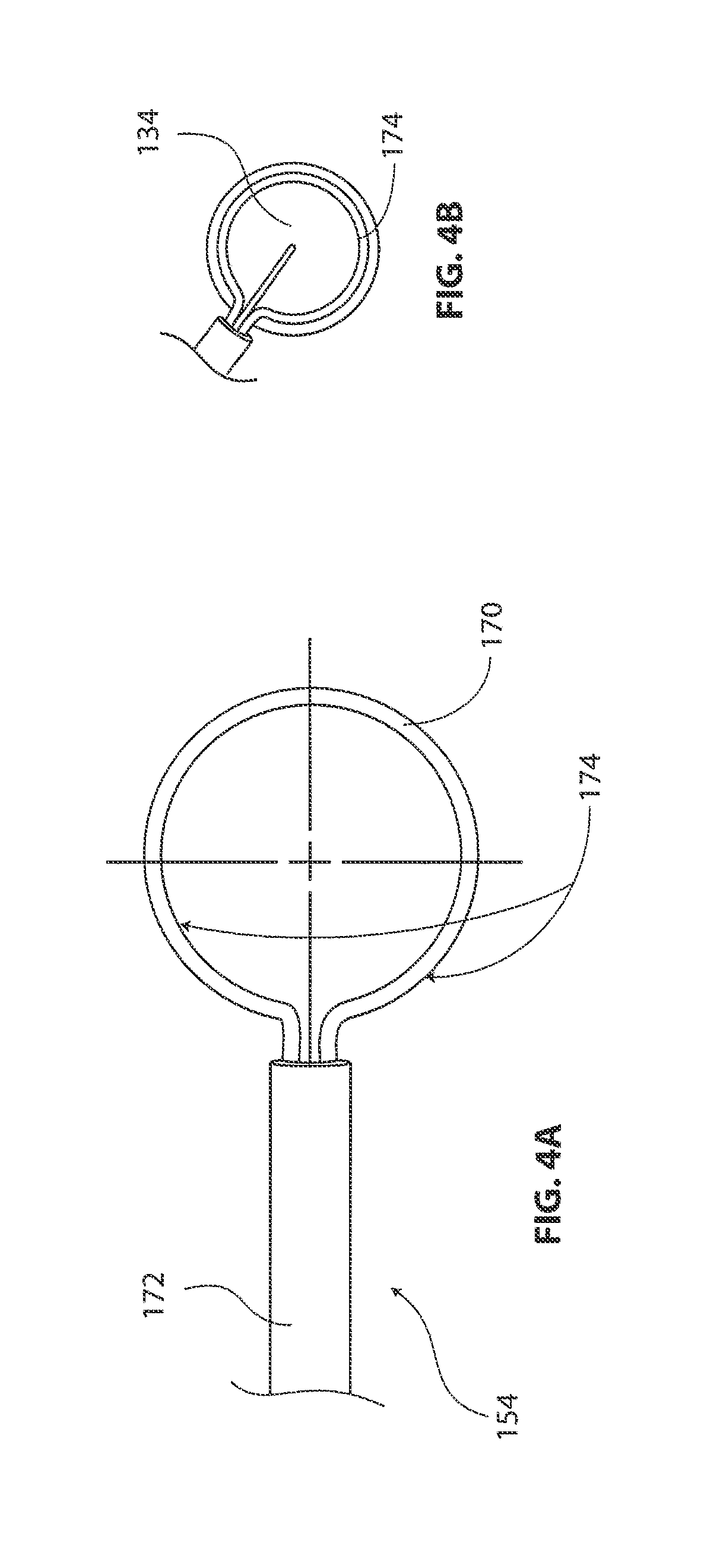
FIG. 4A is a top view of anchor delivery device.
FIG. 4B is a plan view showing a support ring of anchor delivery device overlaying a tendon repair implant.
FIG. 4C is a cross-sectional view of an anchor delivery device.
FIG. 4D is an additional cross-sectional view of the anchor delivery device shown in FIG. 4C.
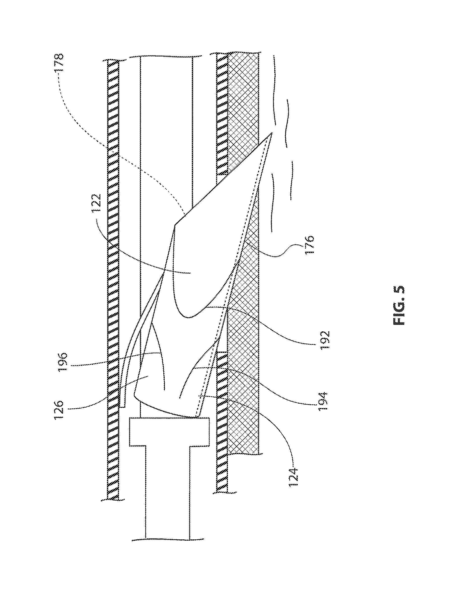
FIG. 5 is an enlarged view of an anchor shown in FIG. 4C.
FIG. 6 is a flow chart describing a method for treating a patient.
DETAILED DESCRIPTION OF THE INVENTION
The following detailed description should be read with reference to the drawings in which similar elements in different drawings are numbered the same. The drawings, which are not necessarily to scale, depict illustrative embodiments and are not intended to limit the scope of the invention.
Related U.S. application Ser. No. 12/684,774 filed Jan. 8, 2010 and entitled Impantable Tendon Protection System and Related Methods, provides an example of a medical device that may be delivered into a patient's shoulder joint through a cannula. During such an arthroscopic procedure, a surgeon's field of view through the cannula or arthroscope is typically very short. Accordingly, it can be difficult to accurately locate a target site for permanently implanting or temporarily placing such a medical device. Further, once a device is placed adjacent the target site and/or unfurled, many or all of the landmarks used by the surgeon to locate the target sight may be obscured. In the particular situation of the device being implanted as described in the above application, the target site may be spherically shaped and comprise slippery tissue, making placement of the implant even more difficult.
During such a delivery procedure, it may be desirable to first affirmatively locate the target site to which the medical device will be attached, and temporarily attach a locating guide to the target site to aid in delivering the medical device, according to aspects of the present detailed description. Once the medical device is attached to the target site, the located guide may be detached and removed. While the descriptions below and associated drawings refer to implanting a tendon protection device in a shoulder joint, in particular a sheet-like structure or disk-like structure, the system and method described herein and modified versions thereof may also be used to aid in temporarily or permanently placing other devices in other locations within a patient.
FIG. 1A is an isometric view of a shoulder 20. Shoulder 20 includes a humerus 22 and a scapula 24. Scapula 24 comprises an acromium 26 and a glenoid fossa 28. The movement of humerus 22 relative to scapula 24 is controlled by a number of muscles including: the deltoid, the supraspinatus, the infraspinatus, the subscapularis, and the teres minor. For purposes of illustration, only the supraspinatus 30 is shown in FIG. 1. With reference to FIG. 1, it will be appreciated that a distal tendon 32 of the supraspinatus 30 meets humerus 22 at an insertion point
In FIG. 1, a head 34 of humerus 22 is shown mating with glenoid fossa 28 of scapula 24 at a glenohumeral joint 38. In FIG. 1, a subacromial bursa 36 is shown extending between acromium 26 of scapula 24 and head 34 of humerus 22. Subacromial bursa 36 is shown overlaying supraspinatus 30 in FIG. 1. Subacromial bursa 36 is one of over one hundred and fifty bursae found the human body. Each bursa comprises a fluid filled sac. The presence of these bursae in the body reduces friction between bodily tissues. Injury and/or infection of the bursa can cause it to become inflamed. This condition is sometimes referred to as bursitis.
A locating guide 100 is also shown in FIG. 1. Locating guide 100 comprises a shaft 102 having a proximal end and a distal end. A handle 104 is fixed to the proximal end of shaft 102. In FIG. 1, a distal portion of shaft 102 is shown extending into an anterior side of shoulder 20 from a location in the front of the patient. The distal portion of shaft 102 may be inserted into the shoulder so that the longitudinal axis of the shaft extends generally parallel or tangent to an outer surface of a rotator cuff tendon (e.g., a supraspinatus tendon). This allows maneuvering the distal end of the shaft 102 to a target site for placing the tendon repair implant. In the exemplary embodiment of FIG. 1, shaft 102 may be moved in a generally posterior direction as the distal end of shaft 102 is advanced into the anterior side of shoulder 20. Shaft 102 may be advanced in other directions to insert the distal portion of shaft 102 without deviating from the spirit and scope of this detailed description. In some cases, for example, shaft 102 may be moved in a generally anterior direction as the distal end of shaft 102 is advanced into the posterior side of shoulder 20. Shaft 102 may also be moved in a generally superior or inferior direction as the distal end of shaft 102 is advanced into shoulder 20 in some cases. In some useful embodiments, locating guide 100 includes a temporary fixation mechanism proximate the distal end of shaft 102. A method in accordance with the present detailed description may include temporarily fixing the distal end of a shaft to a target site and advancing a tendon repair implant, which can include a sheet-like structure or tendon disk, over the shaft for delivering the implant to the target site.
FIG. 1B and FIG. 1C are cross-sectional views illustrating two states of an exemplary temporary fixation mechanism 108. In FIG. 1B, temporary fixation mechanism 108 is shown in a retracted state. In FIG. 1C, temporary fixation mechanism 108 is shown in a fixing state.
Shaft 102 of locating guide 100 comprises core wire 130 and a guide sheath 132. With reference to FIG. 1C, it will be appreciated that locating guide 100 includes a selectively deployable barb 120. In the embodiment of FIG. 1, barb 120 is biased to extend away from a longitudinal axis of core wire 130 as shown in FIG. 1C. In the embodiment of FIG. 1B, however, guide sheath 132 is urging barb 120 toward the longitudinal axis of core wire 130. In FIG. 1C, barb 120 is shown extending through an aperture defined by the wall of guide sheath 132. In one exemplary method of use, the distal end of shaft 102 is positioned adjacent a target site and inserted into the tendon tissue. The barb 120 is then deployed by moving guide sheath 132 longitudinally which temporarily affixes the locating guide 100 to the tendon for providing a track to deliver the tendon repair implant. When implantation is complete, the guide sheath 132 can be returned to its original position which urges the barb 120 against the core wire and releases the tendon. In an alternative embodiment (not shown), a helical screw tip may be employed on the distal end of core wire 130 to temporarily secure guide 100 to the tissue with a twisting motion of core wire 130. The temporary fixation structure can also comprise a projection that inserts into the tendon and holds or fixes a lateral position but can be released from the position by lifting the projection out of the tendon. A suture passed through the tendon may also be used to secure guide 100.
FIG. 2 is a plan view of an exemplary tendon repair implant delivery system 140. The tendon repair implant can be a sheet-like or disk-like structure that overlays a portion of a tendon when implanted. In the embodiment of FIG. 2, tendon repair implant delivery system 140 comprises a delivery system sheath 142 and a handle 104. In the exemplary embodiment of FIG. 2, handle 104 has a pistol grip shape. It will be appreciated that handle 104 may have various shapes in addition to the exemplary shape shown in FIG. 2.
In the embodiment of FIG. 2, a tendon repair implant which comprises a sheet-like or disk-like structure 134 is disposed inside a distal portion 136 of delivery system sheath 142. Tendon repair implant delivery system 140 may be used to deploy tendon repair implant 134 within the body of a patient. Some methods in accordance with this description include attaching the implant to a tendon using a plurality of anchors. Tendon repair implant delivery system 140 may include an anchor delivery device for this purpose. In some useful embodiments, the anchor delivery device is capable of delivering a plurality of anchors for attaching the tendon repair implant to the tendon.
Tendon repair implant delivery system 140 may be used to perform various functions including deploying a sheet-like or disk-like structure within the body of a patient and anchoring the structure to a tendon. Tendon repair implant delivery system 140 includes a plurality of controls that may be used on conjunction with the various functions that can be performed using delivery system 140. The controls of delivery system 140 include a knob 144, a slide button 146, a trigger 148, and a toggling lever 150.
In the embodiment of FIG. 2, the position of delivery system sheath 142 may be altered by moving slide button 146 which is mechanically linked internally to delivery system sheath 142. Two positions of slide button 146 are shown in FIG. 2. In FIG. 2, a first position is shown with solid lines and a second position is shown with dashed lines. When slide button 146 is in the first position, implant delivery sheath will assume the advanced position shown in FIG. 2. When slide button 146 is in the second position, delivery system sheath 142 will assume a retracted position.
Knob 144 of implant delivery system 140 may be used to operate a locating guide 100. For example, knob 144 may be used to actuate a temporary fixation mechanism of locating guide 100. Knob 144 may cause the temporary fixation mechanism of locating guide 100 to alternate between the retracted state and the fixing state. When the temporary fixation mechanism is in the fixing state, it will selectively fix the distal end of locating guide 100 to a target site. For example, knob 144 may be mechanically connected to sheath 132, depicted in FIG. 1B such that actuating knob 144 results in longitudinal movement of sheath 132 to deploy or retract the barb as necessary to temporarily fix the distal end of the location member.
Implant delivery system 140 also includes a toggling lever 150. A support ring sheath of implant delivery system 140 may be advanced and retracted using toggling lever 150. Toggling lever 150 may be moved between a first position and a second position. In FIG. 2, the first position of toggling lever 150 is shown with solid lines and the second position of toggling lever 150 is shown with dashed lines.
When the support ring sheath is retracted, support ring tube will form a support ring. In some embodiments, a plurality of anchors are disposed inside the support ring tube. For example, six anchors may be evenly spaced along the support ring tube. In the embodiment of FIG. 2, trigger 148 may be used to dispense the anchors. In some embodiments, one anchor will be dispensed each time trigger 148 is actuated. In other embodiments, two or more anchors will be dispensed each time trigger 148 is actuated.
FIG. 3 is a cross-sectional view further illustrating a distal portion 136 of delivery system sheath 142. In FIG. 3, a tendon repair implant 134 can be seen residing inside a lumen defined by delivery system sheath 142. In the embodiment of FIG. 3, a locating guide 100, an implant push rod 152, and an anchor delivery device 154 are also disposed in the lumen defined by delivery system sheath 142.
Tendon repair implant 134 of FIG. 3 comprises a first lateral fold 156 and a second lateral fold 158. An intermediate portion 160 of tendon repair implant 134 is disposed between first lateral fold 156 and second lateral fold 158. With reference to FIG. 3, it will be appreciated that a shaft 102 of locating guide 100 extends through a hole in intermediate portion 160 of tendon repair implant 134.
In FIG. 3, a distal portion 162 of tendon repair implant 134 can be seen extending between first lateral fold 156 and an outer edge 166 of tendon repair implant 134. A proximal portion 164 of tendon repair implant 134 can be seen extending between second lateral fold 158 and outer edge 166 of tendon repair implant 134 in FIG. 3. Tendon repair implant 134 may also include a plurality of longitudinal folds (not visible in FIG. 3). For example, tendon repair implant 134 may be folded into a pleated shape including a plurality of longitudinal folds. In some embodiments, the tendon repair implant is folded or otherwise compacted to a collapsed configuration prior to insertion to the target or implant site. When properly positioned at the target site the tendon repair implant is reconfigured to an open or non-collapsed configuration to overlay at least a portion of the tendon. The tendon repair implant may be self-expanding such that when the implant is extended outside the sheath of the delivery system, it unfurls or expands to an open or sheet-like configuration.
In the embodiment of FIG. 3, locating guide 100 comprises a shaft 102. Shaft 102 comprises a guide sheath 132 disposed about core wire 130. In the embodiment of FIG. 3, an implant push rod 152 is disposed about guide sheath 132 of shaft 102. Implant push rod 152 may by used to urge tendon repair implant 134 distally along shaft 102 of locating guide 100.
In the embodiment of FIG. 3, an exemplary anchor delivery device 154 is disposed in the lumen defined by delivery system sheath 142. Anchor delivery device 154 comprises a support ring tube 170 and a support ring sheath 172 that is disposed about support ring tube 170. Support ring tube 170 is biased to form a support ring when support ring sheath 172 is in a retracted position. Support ring tube 170 assumes a contracted shape when support ring tube 170 is retracted into a lumen defined by support ring sheath 172. The operation of anchor delivery device 154 may be further explained with reference to the next figure.
FIG. 4 includes a plurality of additional views further illustrating anchor delivery device 154 shown in the previous figure. FIG. 4A is a top view of anchor delivery device 154. In the embodiment of FIG. 4A, support ring tube 170 is forming a support ring 174. Support ring 174 of FIG. 4A comprises a portion of support ring tube 170 that is extending beyond support ring sheath 172. In the embodiment of FIG. 4B, support ring tube 170 will be urged to assume a contracted shape when support ring tube 170 is retracted into a lumen defined by support ring sheath 172.
FIG. 4B is a plan view showing support ring 174 of anchor delivery device 154 overlaying a tendon repair implant 134. In some exemplary methods in accordance with the present description, support ring 174 is used to hold tendon repair implant 134 in intimate contact with a tendon. Support ring 174 of FIG. 4A comprises a portion of support ring tube 170 that is extending beyond support ring sheath 172. A shaft 102 of a locating guide 100 can be seen extending through a hole in tendon repair implant 134 in FIG. 4B.
FIG. 4C is a cross-sectional view of anchor delivery device 154. In some embodiments, anchor delivery device 154 comprises a plurality of anchors 176 that can be used to fix an implant to a tendon. One anchor 176 is visible in FIG. 4C. The anchor can be a blind anchor that is inserted into the tendon on the bursal side. In the embodiment of FIG. 4C, anchor 176 defines a channel 178. In FIG. 4C, a pull wire 180 can be seen extending through channel 178. A top surface 182 of anchor 176 and a bottom surface 184 of anchor 176 are both visible in FIG. 4C. Top surface 182 defines an open side of channel 178.
Anchor 176 and pull wire 180 are both disposed inside a lumen defined by a support ring tube 170. The wall of support ring tube 170 defines a plurality of apertures 186. Each anchor 176 of anchor delivery device 154 may be selectively urged through an aperture 186 to anchor an implant to a tendon.
With reference to FIG. 4C, it will be appreciated that pull wire 180 has a plurality of flanges 188. In FIG. 4C, a flange 188 can be seen contacting a proximal end of anchor 176. Flange 188 and pull wire 180 may apply force to anchor 176. For example, force from pull wire 180 and flange 188 may be used to urge a distal point 190 of anchor 176 through an implant and into a tendon.
FIG. 4D is an additional cross-sectional view of anchor delivery device 154. In FIG. 4D, anchor 176 is shown extending through an aperture 186 defined by the wall of support ring tube 170. In the embodiment of FIG. 4D, an anchor deflector 193 is applying a deflecting force to anchor 176. This deflecting force is represented with an arrow FD in FIG. 4D. In FIG. 4D, an arrow FA is used to represent a force that flange 188 is applying to anchor 176. An additional arrow FB is also visible in FIG. 4D. Arrow FB represents a pulling force that is being applied to pull wire 180. In the embodiment of FIG. 4, distal point 190 of anchor 176 has penetrated the cuff of a tendon repair implant 134. Distal point 190 is shown residing in a tendon.
FIG. 5 is an enlarged view of anchor 176 shown in the previous figure. With reference to FIG. 5, it will be appreciated that anchor 176 comprises a body 198 having a distal point 190. Body 198 of anchor 176 defines a channel 178. Body 198 includes a first notch 192, a second notch 194, and a third notch 196. First notch 192 defines a first barb 122 of anchor 176. Second notch 194 and third notch 196 define a second barb 124 and a third barb 126 respectively. The barbs of anchor 176 may expand outward once anchor 176 is deployed.
FIG. 6 is a flow chart describing a method for treating a patient. A method in accordance with the present description may include accessing a target site in the body of a patient. In some applications, arthroscopic equipment may be used to access a joint (e.g., a shoulder joint) in the patient's body. The arthroscopic equipment may include, for example, a cannula. The cannula may be positioned so that the distal end of the cannula is inside the shoulder of the patient. The cannula defines a lumen. Various devices may be advanced through a proximal opening of the cannula and into the lumen defined by the cannula. The cannula then guides the device into the shoulder.
A method in accordance with the present detailed description may include anchoring the distal end of a guide shaft to a target site and advancing a tendon repair implant over the shaft for delivering the tendon repair implant to the target site. Some methods in accordance with this description include attaching the implant to a tendon using a plurality of anchors. An anchor delivery device may be used for this purpose. In some useful embodiments, the anchor delivery device is capable of delivering a plurality of anchors for attaching the implant to the tendon.
A therapeutic agent may be applied to the tendon repair implant prior to positioning at the target site. Therapeutic agents can include: drugs, anti-inflammatory agents, painkillers, antibiotics, proteins, hormones, growth factors, and growth factor sources. Growth factor sources may include, for example, platelets and platelet rich plasma (PRP). A tendon repair implant may contain calcium chloride for causing platelet aggregation, which will cause release of growth factors. Examples of growth factors that may be suitable in some applications include but are not limited to heparin binding growth factor ("HBGF"), platelet-derived growth factor ("PDGF"), transforming growth factor alpha or beta ("TGF-.alpha." or "TGF-.beta."), basic fibroblast growth factor ("bFGF"), epidermal growth factor ("EGF"), and vascular endothelial growth factor ("VEGF"). Examples of hormones that may be suitable in some applications include but are not limited to insulin, glucagon, and estrogen. It will be appreciated that therapeutic agents can be delivered to the target site apart from the tendon repair implant, either before or after placement of the implant.
While exemplary embodiments of the present invention have been shown and described, modifications may be made, and it is therefore intended in the appended claims to cover all such changes and modifications which fall within the true spirit and scope of the invention.
* * * * *
D00000
D00001
D00002
D00003
D00004
D00005
D00006
D00007
XML
uspto.report is an independent third-party trademark research tool that is not affiliated, endorsed, or sponsored by the United States Patent and Trademark Office (USPTO) or any other governmental organization. The information provided by uspto.report is based on publicly available data at the time of writing and is intended for informational purposes only.
While we strive to provide accurate and up-to-date information, we do not guarantee the accuracy, completeness, reliability, or suitability of the information displayed on this site. The use of this site is at your own risk. Any reliance you place on such information is therefore strictly at your own risk.
All official trademark data, including owner information, should be verified by visiting the official USPTO website at www.uspto.gov. This site is not intended to replace professional legal advice and should not be used as a substitute for consulting with a legal professional who is knowledgeable about trademark law.