Hernia Stapler With Integrated Mesh Manipulator
Amid; Parviz K. ; et al.
U.S. patent application number 12/880492 was filed with the patent office on 2010-12-30 for hernia stapler with integrated mesh manipulator. Invention is credited to Parviz K. Amid, Scott Arp, Christian Martin.
| Application Number | 20100327042 12/880492 |
| Document ID | / |
| Family ID | 41065857 |
| Filed Date | 2010-12-30 |


View All Diagrams
| United States Patent Application | 20100327042 |
| Kind Code | A1 |
| Amid; Parviz K. ; et al. | December 30, 2010 |
HERNIA STAPLER WITH INTEGRATED MESH MANIPULATOR
Abstract
A surgical stapler for use during an open hernia repair comprises an elongated shaft having a handle 120 at its proximal end and a downwardly disposed staple discharge head 130 at its distal end. A squeeze trigger 122 on the handle 120 is operable to cause a supply of staples 160 to be selectively discharged from the port. One or more mesh manipulators 150 are provided on the head 130 and serve to assist in positioning or otherwise manipulating surgical mesh prior to fixation with the staples.
| Inventors: | Amid; Parviz K.; (Calabasas, CA) ; Martin; Christian; (Miami, FL) ; Arp; Scott; (Village of Palmetto Bay, FL) |
| Correspondence Address: |
    Woodard, Emhardt, Moriarty, McNett & Henry LLP
    111 Monument Circle, Suite 3700
    Indianapolis
    IN
    46204-5137
    US
|
| Family ID: | 41065857 |
| Appl. No.: | 12/880492 |
| Filed: | September 13, 2010 |
Related U.S. Patent Documents
| Application Number | Filing Date | Patent Number | ||
|---|---|---|---|---|
| PCT/US2009/037119 | Mar 13, 2009 | |||
| 12880492 | ||||
| 61036644 | Mar 14, 2008 | |||
| Current U.S. Class: | 227/176.1 ; 606/151 |
| Current CPC Class: | A61B 17/0684 20130101; A61B 2017/00349 20130101; A61B 17/00234 20130101; A61B 17/0644 20130101; A61F 2/0063 20130101 |
| Class at Publication: | 227/176.1 ; 606/151 |
| International Class: | A61B 17/068 20060101 A61B017/068 |
Claims
1. A surgical stapler for use during an open hernia repair: comprising: an elongated shaft having a handle at its proximal end and a downwardly disposed staple discharge port at its distal end, wherein the handle is operable to cause a supply of staples to be selectively discharged from the port; and one or more mesh manipulators near the staple discharge port and projecting distal to the plane defined by the port so as to be useful in manipulating a surgical mesh.
2. The stapler of claim 1 wherein the one or more mesh manipulators comprise one or more fixed prongs extending from a discharge head defining the discharge port.
3. The stapler of claim 2 wherein a plurality of fixed prongs are disposed on opposing sides of the discharge port.
4. The stapler of claim 2 wherein the one or more mesh manipulators comprise a wire having a non-linear portion.
5. The stapler of claim 1 wherein the one or more mesh manipulators are retractable.
6. The stapler of claim 1 wherein the stapler comprises an angled array of staples.
7. The stapler of claim 1 wherein the stapler comprises a staple magazine mounted to a downwardly disposed discharge head and to the elongated shaft.
8. The stapler of claim 1 wherein a staple former in the discharge head is driven by a trigger in the handle via an actuating assembly extending through the shaft.
9. The stapler of claim 8 wherein the actuating assembly comprises a rigid rod in a straight section of the shaft and a flexible member spanning a curved section of the shaft.
10. The stapler of claim 9 wherein the flexible member is planar.
11. A surgical stapler comprising: an elongated shaft having a handle at its proximal end, a downwardly disposed discharge head at its distal end, and an angled magazine of staples mounted between the discharge head and the shaft.
12. The surgical stapler of claim 11 wherein the discharge head is driven by a trigger in the handle via an actuating assembly extending longitudinally through the shaft.
13. The surgical stapler of claim 12 wherein the actuating assembly comprises a rigid rod in a straight section of the shaft and a flexible member spanning a curved section of the shaft.
14. The surgical stapler of claim 11 further comprising one or more mesh manipulators extending from the discharge head.
15. The surgical stapler of claim 14 wherein the one or more mesh manipulators comprise a plurality of fixed prongs.
16. The surgical stapler of claim 14 wherein the one or more mesh manipulators are retractable.
17. A method of attaching a surgical mesh comprising: providing a surgical stapler comprising: an elongated shaft having a handle at its proximal end and a downwardly disposed staple discharge port at its distal end, wherein the handle is operable to cause a supply of staples to be selectively discharged from the port; and one or more mesh manipulators near the staple discharge port; using the mesh manipulator to position the mesh; and using the stapler to attach the mesh to tissue.
18. The method of claim 17 wherein the tissue is the inguinal ligament.
19. The method of claim 17 wherein the mesh manipulator comprises one or more prongs extending from a discharge head of the stapler.
20. The method of claim 17 wherein the mesh manipulator comprises a wire
21. An apparatus for use by a person stapling mesh to body tissue at a site of inguinal hernia surgery and comprising: a handle for holding the apparatus adjacent the surgery site, and having a proximal end and a distal end; a shaft defining a longitudinal axis and having a proximal end and a distal end and having the proximal end mounted to the distal end of the handle; a staple discharge head having one end with a mounting portion connected to the distal end of the shaft, and having another end with a staple exit port; the head adapted to fire a staple out from the head through the port along a line and in a direction away from the handle, wherein the direction of staple firing is downward relative to the longitudinal axis of the shaft; and a plurality of mesh manipulating prongs extending from the head, wherein said prongs are configured to engage a mesh useful for embedding in a body cavity during inguinal hernia surgery, for connecting and moving said mesh to a location for stapling the mesh to body tissue at the surgery site.
22. The apparatus of claim 21 wherein the prongs extend at least about 3 mm distal to a plane defined by a staple outlet port in the head.
23. During inguinal hernia repair, a method of attaching a mesh covering herniated membrane, to body tissue adjacent and bordering the site of the herniation, and comprising: inserting the head of a stapling apparatus into an opening bordered by said tissue and directing a staple discharge port downward toward said mesh at a near side of said opening and firing staples from said port through said mesh into some of said tissue adjacent said herniation, at multiple locations on the near side of said opening; moving the head of a stapling apparatus in an opening bordered by said tissue and directing a staple discharge port upward toward said mesh at a far side of said opening and firing staples from said port through said mesh into some of said tissue, at multiple locations on the far side of said opening.
24. The method of claim 23 and further comprising: engaging said mesh with one or more mesh manipulating members mounted to said head; and moving said mesh with said probe to position said mesh at a location on said tissue where a staple is to be fired into said mesh and said tissue.
25. The method of claim 24 wherein the mesh manipulating members comprise a plurality of prongs extending from said head.
Description
RELATED APPLICATION DATA
[0001] This application is a continuation of PCT/US2009/037119 filed Mar. 13, 2009, which claims the benefit of U.S. Provisional Application Ser. No. 61/036,644 filed Mar. 14, 2008, the disclosure of which are hereby incorporated by reference.
BACKGROUND
[0002] This application is generally related to means for applying surgical staples to fasten a surgical mesh. More specifically, but not exclusively, it is related to a surgical stapler having a distal manipulator for positioning a surgical mesh prior to application of the staples.
[0003] Chapters 14 and 23, "Lichtenstein Tension-Free Hernioplasty For The Repair of Primary and Recurrent Inguinal Hernias", and "The Transabdominal Preperitoneal Laparoscopic Herniorrhaphy", pages 149-157, and 256-268 of Nyhus and Condon's Hernia, Fifth Edition, edited by Robert J. Fitzgibbons and A. Gerson Greenburg, published by Lippincott Williams & Wilkins, Philadelphia, 2002, describe some procedures for repair of inguinal hernias. A sheet of monofilamented polypropylene mesh is mentioned as a material suitable for use in such procedures. After shaping and placement of the mesh in the repair site, it is sutured to adjacent tissue.
[0004] While suturing is a long-standing practice for securing the mesh, some stapling is frequently favored because of the speed and relative ease of doing it. At some locations desired for attachment of the mesh to tissue, stapling is possible, but holding and stapling the mesh to tissue at some other locations where attachment is desired, can be challenging, if not impossible, for one pair of hands. Improvement is needed.
SUMMARY
[0005] The present invention provides systems and techniques for applying surgical staples and for using staples to hold a surgical mesh, for example during an inguinal hernia repair. The systems and techniques may also be applied during ventral/incisional hernia repair, used for skin closure or used in other surgical procedures as would occur to the skilled artisan. While the actual nature of the invention covered herein can only be determined with reference to the claims appended hereto, certain aspects of the invention that are characteristic of the embodiments disclosed herein are described briefly as follows.
[0006] According to one aspect, an improved surgical stapler for attaching surgical mesh includes an elongated shaft having a handle at its proximal end and a downwardly disposed staple discharge port at its distal end. The handle includes a trigger that is configured to cause a supply of staples to be selectively discharged from the discharge port. One or more mesh manipulators are provided near the discharge port and are operable to assist in the positioning of the surgical mesh prior to firing a staple to secure the mesh to tissue. The mesh manipulators may be fixed in position or made to be retractable. In one particular aspect, the mesh manipulator is in the form of an elongated shaft that is selectively extended from a housing mounted beneath the elongated shaft. In another particular aspect, the mesh manipulator comprises a plurality of prongs mounted on oppositely disposed sides of the discharge port.
[0007] According to another aspect, a novel surgical stapler comprises an elongated shaft having a handle at its proximal end, a downwardly disposed discharge head at its distal end, and an angled magazine of staples mounted between the discharge head and the shaft. A staple former in the discharge head is driven by a trigger in the handle via an actuating member extending through the shaft. The actuating member may comprise a rigid rod in a straight section of the shaft and a flexible member spanning a curved section of the shaft.
[0008] These and other aspects are discussed below.
BRIEF DESCRIPTION OF THE DRAWINGS
[0009] FIG. 1 is a side elevational view of an embodiment of the present invention.
[0010] FIG. 1A is an enlarged fragmentary view of a portion of the stapler head showing a staple projecting from the staple exit port and showing the tip of a mesh positioning probe wire.
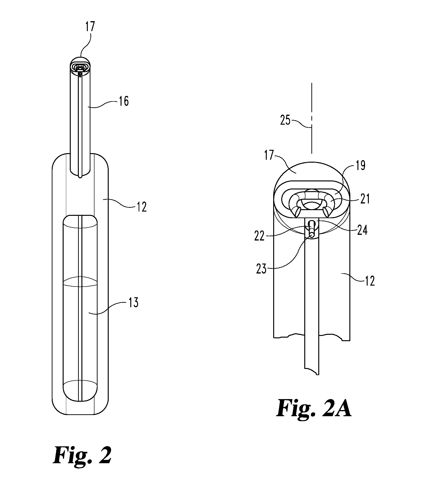
[0011] FIG. 2 is a front elevational view of the stapler.
[0012] FIG. 2A is an enlarged fragmentary front view of the stapler head portion.
[0013] FIG. 3 is an enlarged fragmentary schematic view of the stapler head portion with a probe wire type curved forward to push mesh to a desired position on body tissue for stapling.
[0014] FIG. 3A illustrates the actual use of the wire pushing a piece of mesh forward.
[0015] FIG. 4 is a view similar to FIG. 3 but showing the probe wire tip portion angled backward to pull the mesh.
[0016] FIG. 4A is similar to FIG. 3A but showing the tip of FIG. 4 engaged to pull the mesh.
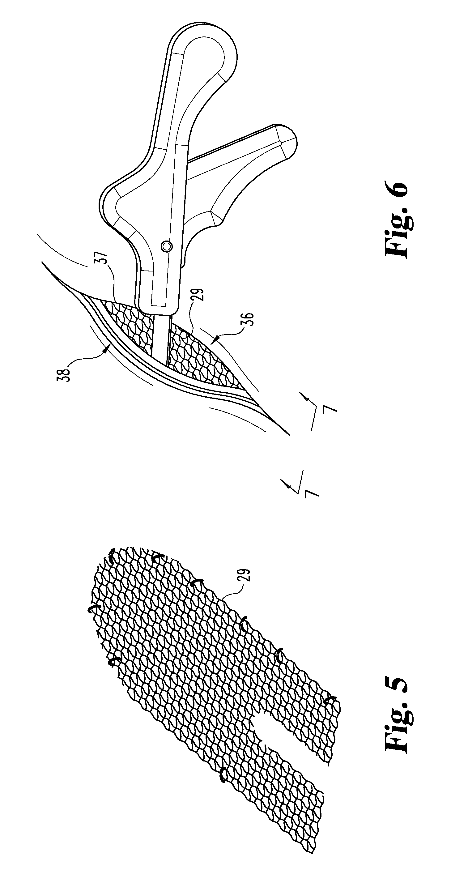
[0017] FIG. 5 is a schematic view of a piece of mesh shaped for placement in the repair site and illustrating the location where stapling is desired.
[0018] FIG. 6 is a schematic view of the repair site with stapler head in the opening.
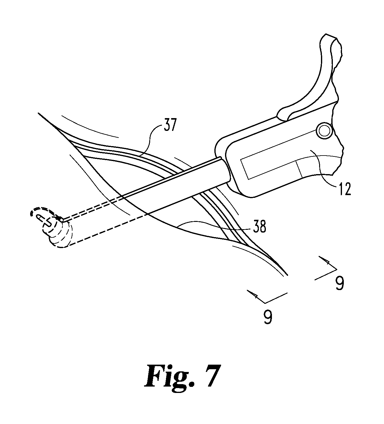
[0019] FIG. 7 is a schematic view of the repair site with the stapler in position for stapling the mesh to the underside of body tissue at the far side of the opening.
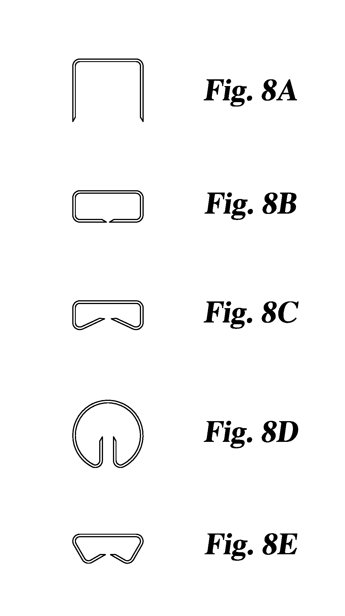
[0020] FIG. 8A is a view of a staple before installation.
[0021] FIGS. 8B, 8C, 8D and 8E represent four possible different configurations of the staple after stapling, the shapes being determined by staple forming features specified for incorporation in the stapler head.
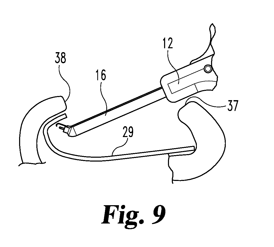
[0022] FIG. 9 is a schematic of the site and viewed in the direction of arrows 9-9 in FIG. 7.
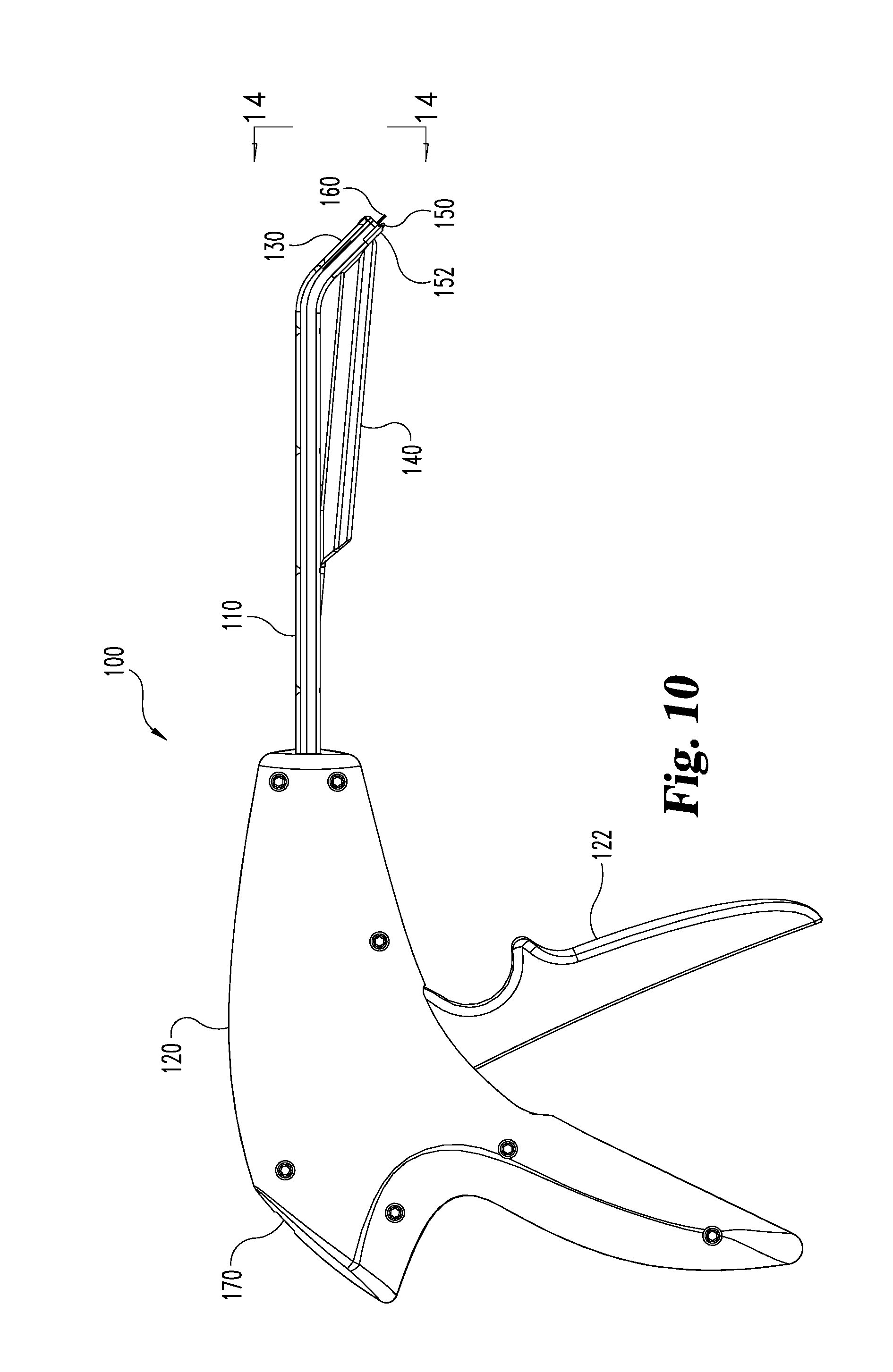
[0023] FIG. 10 is a side elevational view of a stapler of new construction.
[0024] FIG. 11 is an exploded view of the FIG. 10 stapler with the second half of the handle omitted for clarity.
[0025] FIG. 12 is an underside view of the staple discharge head of the FIG. 10 stapler with the front wall piece 152 and the supporting magazine 140 for the staples removed for clarity.
[0026] FIG. 13 is the underside view of FIG. 13 with a staple partially formed.
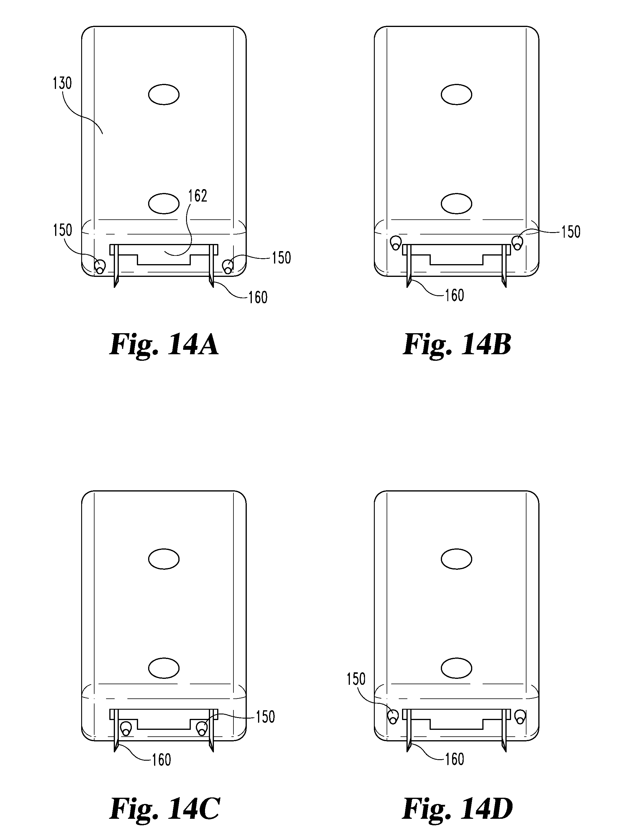
[0027] FIG. 14A is an end view of the discharge head of the FIG. 10 stapler, viewed in the direction of arrows 14-14 in FIG. 10.
[0028] FIGS. 14B-D are views of alternative arrangements for the prongs on the discharge head.
DETAILED DESCRIPTION OF THE ILLUSTRATED EMBODIMENTS
[0029] Referring to FIGS. 1-2A, a stapler 11 has a handle 12 with a trigger 13 pivotally mounted to the handle at 14. A tube 16 is fixed to the handle and has a stapler head portion 17 at its distal end. The head portion turns downward at an angle of about forty degrees (A in FIG. 1) from the axis 18 and has a staple discharge port 19 through which staples are shot, one staple for each trigger pull. The trigger coupling to the staple shooter is a two-stage system whereby the staple 21 can be advanced from within the head to a position shown in FIGS. 1 and 1A. Then, upon further pull of the trigger it can be shot through the mesh into the tissue.
[0030] One inventive feature is the provision of a mesh manipulator near the outlet port of the stapler. As used herein, a "mesh manipulator" does not include the staple itself, but rather it is a structure other than the staple that is operable to be used to manipulate surgical mesh. In FIGS. 1 and 1A, the mesh manipulator comprises an elongated member or wire 22 having a distal portion including a tip 23 which projects downward under the head 17 in the plane 25 (FIG. 2A) containing the axis 18 of the tube 16 and bisecting the handle 12. This elongated member extends from the tip portion backward through a channel 24 at the bottom of the tube 16. A wire control button 26 slidable on the channel and connected to the proximal end of the wire, is provided to slide the wire forward to extend the tip 23 farther below the staple outlet port 19, or retract it into the channel 24 when, and to what extent desired by the surgeon. Other locations for the wire control knob or button can be used when and desired by the user. One example is in the handle itself.
[0031] For purposes of useful mesh manipulation, the wire 22 would often, but not always, be positioned such that the tip 23 projects several millimeters beyond the plane 40 defined by the outlet port 19, as shown in FIG. 1A. For example, it is expected that useful mesh manipulation can be achieved when the tip 23 is at least about 2 mm, 3 mm, 4 mm, 5 mm, 6 mm, 7 mm, 8 mm, 9 mm, or 10 mm distal to plane 40.
[0032] Referring now to FIGS. 3 and 3A, a wire 27 is provided with a curved tip portion 28 curved downward and forward for insertion through the mesh 29 and pushing it forward in the direction of arrow 31 to move it to the position desired for stapling. This forward movement may be made by moving the stapler itself using the handle or by moving the wire by moving the slider button 26.
[0033] Referring to FIGS. 4 and 4A, the wire 32 has a tip portion 33 which is curved rearward to enable the wire tip to pass through the mesh 29 and pull it rearward in the direction of arrow 34 to position the mesh where desired relative to the location at which the stapling through the mesh to the tissue is desired.
[0034] Referring now to FIG. 5, there is a schematic showing the mesh 29 cut from a sheet into a shape desired for placement at the surgery site. There are shown eleven sites at the edges of the mesh indicating where stapling inboard from the edges is desired. This is an example, as different sizes and shapes and numbers of staples may be chosen depending upon the requirements of the site.
[0035] FIG. 6 is a schematic illustration of the site with the staple head inserted into the opening 36. Consider that the opening edge 37 nearest the surgeon is referred to in this context, as the near edge, and the opposite edge 38 is the far edge. Attachment of the mesh to tissue below the near edge 37 by stapling can be relatively straight forward with the stapler oriented as shown in FIG. 6, but pulled outward to place the head at the near edge 37 and move the head downward to the mesh and shoot the staple down into the mesh with the prongs into the tissue below. On the opposite edge, the mesh is to be stapled to the upper inside face of the tissue. That is extremely difficult with conventional instruments. But the present invention is capable of being turned upside down as shown in FIGS. 7 and 9 so that the discharge port 19 and wire 23 are facing upwardly to the tissue and pushed or pulled by a wire tip such as shown in FIG. 3 or FIG. 4, depending upon the most effective approach to push or pull the mesh to the location desired for stapling and then fire the staple upward with the prongs through the mesh and into inverted or lofted tissue.
[0036] In FIG. 1, for example and without limitation, the head 17 has the discharge port angled down as shown at A. As an example, this angle can be between 30 and 50 degrees from the center line 18 of the shaft. 45 degrees might be optimal.
[0037] The total offset B between the bottom of the head and top of the shaft is preferably between 12 and 25 millimeters. Other angles and offset dimensions may be used if desired or necessary to the particular surgical site. The overall length between the head and the proximal end of shaft 16 at its entrance to the handle 12 may be 85 millimeters, for example. Again, other dimensions may be determined according to the preference of the surgeon and the nature of the surgical site. The same is true as to the shape and nature of the handle, one example of a different shape is illustrated in FIGS. 10-11 as will be described. The width of the staple between the prongs may be 5 millimeters, for example, but staples of other widths might be selected for particular cases. For example, it may be desirable to produce a fully formed box staple using 0.5 mm staple wire wherein the formed staple has a width of about 7.5 mm and a height of about 3.5 mm. In some tools, it might be considered desirable to make the shaft rotatable in the handle and/or to provide an articulation joint in the shaft near where it enters the handle, but, for the present, it appears that simply inverting the handle from the attitude as shown in FIG. 1 to that as shown in FIGS. 7 and 9 would appear to be adequate. A variety of mechanisms for discharging a staple can be implemented. For example, U.S. Pat. No. 5,829,662 and U.S. Pat. No. 5,743,456 describe endoscopic stapling equipment that could be adapted to implement the present invention.
[0038] Referring now to FIGS. 10-14A, stapler 100 comprises a handle unit 120 and a downwardly disposed discharge head 130 at either end of an elongated shaft 110. A staple magazine 140 containing a supply of staples (e.g. 15) is mounted to the underside of the shaft 110. Trigger 122 is operative to cause a staple 160 to be formed and discharged from the outlet port 162 of head 130. Successive pulls of the trigger form and discharge successive staples from the magazine 140, and a running staple count is displayed in a window at 170.
[0039] Formation and discharge of a staple is accomplished via a single stroke of pusher plate 116, which is coupled to trigger 122 via a mechanical linkage that extends through the shaft 130. More specifically, drive block 125 is mounted in a slot in housing 123 with one end of compression spring 127 over tab 126 and the other end against tab 124. The drive block 125 is coupled to a driver 113 or rigid bar, which is slidably disposed in the channel of shaft 110 defined between the upper cover 111 and base 114. A stiffener 112 is also provided in the shaft channel to increase structural rigidity of the elongated straight portion of the shaft 110. A flexible pusher 115 is coupled to the end of driver 113 and traverses the curved portion of channel, which includes support ribs for flexible pusher 115 in the upper cover 111 to reduce the possibility that the flexible pusher 115 would buckle or otherwise deform. Pusher plate 116 is laminated to the distal end of flexible pusher 115 for a seamless connection. Other connections are possible as well.
[0040] In operation, squeezing the trigger 122 drives block 125 to the right (FIGS. 10, 11), overcoming the restoring forces of springs 127, 128. Springs 127 and 128 each function as a return spring, thereby providing redundancy, but their spring parameters may be selected to produce a desired effect (e.g. substantially increased return force at max trigger depression). As block 125 travels right, a one way clutch assembly 129 engages cogs (not shown) on the underside of block 125 to prevent retraction of block 125 short of a full stroke. In addition, shuttle plate 176 is carried above block 125 and operates to advance numbered ribbon 172, which is sandwiched between shuttle plate 176 and stay plate 174 and provides a running count of staples via a window adjacent backing plate 170.
[0041] At the beginning of a stoke, pusher plate 116 is withdrawn into the discharge head 130, and the first staple in the magazine 140 is advanced into the firing breech. As shown in FIGS. 12 and 13, the staples in the magazine 140 are in the form of an angled stack, with each staple 160 in the stack oriented in its firing direction (i.e. parallel to the back wall 132 of the breech) and the axis of the stack 40-50.degree. from orthogonal to the firing direction.
[0042] As illustrated, the staples in the magazine are generally "M" shaped and are mounted over the front rails of a holder 144, with each hump over one of the rails. A cover plate 143 is secured to the top of holder 144 and a spring pusher 145 biases the staple stack 160 towards the open, angled end of the holder 144. As illustrated, the spring biasing pusher 145 has an uncompressed length greater than the length of the staple stack, which can serve to provide a more constant force on the staple stack as staples are discharged. Guide 146 is positioned at the open end of holder 144 and provides angled fingers that prevent the staples from dropping out the angled, open end prematurely. The staple magazine 140 is mounted to supporting rails on base 114 and covered by a protective shroud 142, and front wall piece 152 is secured to complete the assembly.
[0043] As it advances in its stroke, the forming fingers 135 of pusher plate 116 pick off the first staple from the stack and form the staple around anvil 133. FIG. 13 illustrates a partially formed staple extending from outlet port 162. Continuation of the forming fingers 135 serves to fully form the staple into a desired box like shape, and preferably with the staple prongs inverted slightly rearward. Retraction of forming fingers 135 releases the leaf springs 134, which had been displaced on the downstroke, which serves to displace the now-formed staple from anvil 133. Because the formed staple is narrower, it slips readily through the wider central opening of outlet port 162, as shown in FIGS. 14A-D.
[0044] As illustrated, stapler 100 includes fixed prongs 150 on the underside outside of outlet port 162. Prongs 150 serve as mesh manipulators and may be used in any fashion contemplated herein. FIGS. 14B-D provide illustrations of additional or alternative locations for mesh manipulating prongs about the staple discharge port. Fixed prongs can also be used in combination with a retractable wire to provide further combinations of manipulating capabilities.
[0045] It is also contemplated that stapler 100 can be used without any means for mesh manipulation.
[0046] Numerous variations of the staplers described herein can be employed. For example, it may be desirable to provide one or more points of articulation along the shaft of the staplers described. As one example, a joint capable of 90.degree. articulation can be along shaft 110, for example near where shaft 110 and handle 120 meet. The provision of such an articulation joint may make it easier for the right handed surgeon, when operating on a right inguinal hernia, to place the staples that attach the mesh to the inguinal ligament.
[0047] Staples used herein can be absorbable or non absorbable with material inside the absorbable material for forming the staple. Square shaped, round shaped, G shaped, etc. The staples can be stacked together along a rack inside the shaft that guides the staples to the distal end of the shaft with a spring loaded action, or a mechanism in the handle.
Procedures
[0048] Either under local anesthesia with sedation or general anesthesia, the lower abdomen is prepped and draped. A linear 6 to 8 cm. skin incision is made along the natural skin lines. Hemostasis is obtained. The external oblique aponeurosis is divided, exposing the spermatic cord. Depending on what type of hernia, the hernia sac is dissected from adjacent tissues, emptied of any contents and pushed back into the peritoneal cavity. The mesh to be used, is cut to its standard shape and size, and a tail slit is placed to accommodate the spermatic cord. The stapler is then used to fix the mesh to the insertion of the rectus sheath and along the inguinal ligament. More specifically, the stapler is used to fix the mesh to the rectus sheath, above its insertion to the pubic bone. (The stapler is sized and shaped to assure the safety of the femoral vessels and nerve.) The upper edge of the mesh is stapled to the rectus sheath and the internal oblique apponeurosis avoiding the iliohypogastric nerve. Either a staple or a single non-absorbable suture is then placed through the lower edges of the tails at the level of the internal ring. The wound is then closed in layers after all bleeding has been stopped and the sponge and instrument count is correct. The wound (i.e. the skin) can be closed with the stapler or with a conventional suture.
[0049] It is to be appreciated that what has been described includes an improved surgical stapler for attaching surgical mesh, comprising an elongated shaft having a handle at its proximal end and a downwardly disposed staple discharge port at its distal end, wherein the handle is operable to cause a supply of staples to be selectively discharged from the port; and one or more mesh manipulators near the port and projecting distal to the plane defined by the port.
[0050] What has also been described includes an apparatus for use by a person stapling mesh to body tissue at a site of inguinal hernia surgery and comprising: a handle for holding the apparatus adjacent the surgery site, and having a proximal end and a distal end; a shaft defining a longitudinal axis and having a proximal end and a distal end and having the proximal end mounted to the distal end of the handle; a staple discharge head having one end with a mounting portion connected to the distal end of the shaft, and having another end with a staple exit port; the head adapted to fire a staple out from said head through said port along a line and in a direction away from the handle, wherein the direction of staple firing is downward relative to the longitudinal axis of the shaft; an elongated member mounted to said shaft and extending generally parallel to the shaft and in a direction forward away from said handle, the member having a distal end portion in a plane containing the direction of staple firing, and the distal end portion of said member being spaced from said line and under the line; and the distal end portion of said member having a tip configured to engage a mesh useful for embedding in a body cavity during inguinal hernia surgery, for connecting and moving said mesh to a location for stapling the mesh to body tissue at the surgery site. In one refinement, the distal end portion of said member is strait and curves downward and then forward in said plane to said tip. In another refinement, the distal end portion of said member is strait and curves downward and then rearward in the plane to the tip. In another refinement, a guide on the shaft receives the elongated member and has a proximal end near the handle and a distal end opening exposing the distal end portion of the wire forward of the distal end opening of said guide, and confining the elongated member from the distal end portion of the member rearward to a location adjacent the handle. It may further include a manipulator on the elongated member adjacent the handle for alternately advancing and retracting the tip of the member.
[0051] What is also described is an apparatus for use in stapling mesh to body tissue at a site of inguinal hernia repair surgery and comprising: a shaft having a proximal end and a distal end; a staple discharging head at the distal end of the shaft; a staple inside the head, the staple having a generally U-shaped configuration with spaced prongs in a first plane; and a discharge port on the head for discharge of said staple outward from said head through the discharge port; and a mesh manipulator connected to the head and having a tip adjacent the port the tip of the manipulator is spaced from said first plane a short distance from said first plane to avoid contact by the staple when discharged outward from the port into the mesh.
[0052] What is also described includes, during inguinal hernia repair, a method of attaching a mesh covering herniated membrane, to body tissue adjacent and bordering the site of the herniation, and comprising: inserting the head of a stapling apparatus into an opening bordered by said tissue and directing a staple discharge port downward toward said mesh at a near side of said opening and firing staples from said port through said mesh into some of said tissue adjacent said herniation, at multiple locations on the near side of said opening; moving the head of a stapling apparatus in an opening bordered by said tissue and directing a staple discharge port upward toward said mesh at a far side of said opening and firing staples from said port through said mesh into some of said tissue, at multiple locations on the far side of said opening. The method may further include engaging said mesh with a probe point mounted to said head and located between said port and said mesh, and moving said mesh with said probe to position said mesh at a location on said tissue where a staple is to be fired into said mesh and said tissue. The method may further include moving said mesh is by pushing said mesh with said probe point and/or pulling said mesh with said probe point. Pulling the mesh may be used to lift said mesh on said far side. The mesh may be pierced to facilitate said moving of said mesh.
* * * * *
D00000
D00001
D00002
D00003
D00004
D00005
D00006
D00007
D00008
D00009
D00010
D00011
XML
uspto.report is an independent third-party trademark research tool that is not affiliated, endorsed, or sponsored by the United States Patent and Trademark Office (USPTO) or any other governmental organization. The information provided by uspto.report is based on publicly available data at the time of writing and is intended for informational purposes only.
While we strive to provide accurate and up-to-date information, we do not guarantee the accuracy, completeness, reliability, or suitability of the information displayed on this site. The use of this site is at your own risk. Any reliance you place on such information is therefore strictly at your own risk.
All official trademark data, including owner information, should be verified by visiting the official USPTO website at www.uspto.gov. This site is not intended to replace professional legal advice and should not be used as a substitute for consulting with a legal professional who is knowledgeable about trademark law.