Delivery device including reactive material for programmable discrete delivery of a substance
Dang , et al. January 5, 2
U.S. patent number 10,881,788 [Application Number 14/928,508] was granted by the patent office on 2021-01-05 for delivery device including reactive material for programmable discrete delivery of a substance. This patent grant is currently assigned to International Business Machines Corporation. The grantee listed for this patent is International Business Machines Corporation. Invention is credited to Bing Dang, Gregory M Fritz, Eric P Lewandowski, Joana S. B. T. Maria, Bucknell C Webb, Steven L Wright.

| United States Patent | 10,881,788 |
| Dang , et al. | January 5, 2021 |
Delivery device including reactive material for programmable discrete delivery of a substance
Abstract
A digital biomedical device includes a substrate forming a cavity, a seal formed around the cavity, a lid coupled to the substrate by the seal, a reactive metal structure comprising a plurality of metal layers, wherein the reactive metal structure is a component of at least one of the substrate and the lid, a metal trace configured to initiate a self-propagating reaction between the plurality of metal layers of the reactive metal structure and release contents of the cavity, and a power supply configured to apply an electric current to the metal trace.
| Inventors: | Dang; Bing (Chappaqua, NY), Fritz; Gregory M (Wakefield, MA), Lewandowski; Eric P (Morristown, NJ), Maria; Joana S. B. T. (New York, NY), Webb; Bucknell C (Yorktown Heights, NY), Wright; Steven L (Cortlandt Manor, NY) | ||||||||||
|---|---|---|---|---|---|---|---|---|---|---|---|
| Applicant: |
|
||||||||||
| Assignee: | International Business Machines
Corporation (Armonk, NY) |
||||||||||
| Family ID: | 57571037 | ||||||||||
| Appl. No.: | 14/928,508 | ||||||||||
| Filed: | October 30, 2015 |
Prior Publication Data
| Document Identifier | Publication Date | |
|---|---|---|
| US 20170119960 A1 | May 4, 2017 | |
| Current U.S. Class: | 1/1 |
| Current CPC Class: | A61M 5/14276 (20130101); A61M 5/14 (20130101); A61M 2205/0277 (20130101); A61M 2205/04 (20130101); A61M 2205/0244 (20130101) |
| Current International Class: | A61M 5/142 (20060101) |
References Cited [Referenced By]
U.S. Patent Documents
| 3993071 | November 1976 | Higuchi et al. |
| 4917895 | April 1990 | Lee et al. |
| 4941205 | July 1990 | Horst et al. |
| 5366454 | November 1994 | Currie et al. |
| 5474529 | December 1995 | Arenberg |
| 5606323 | February 1997 | Heinrich et al. |
| 5912632 | June 1999 | Dieska et al. |
| 6068853 | May 2000 | Giannos et al. |
| 6243013 | June 2001 | Duan et al. |
| 6334859 | January 2002 | Richter |
| 6436853 | August 2002 | Lin et al. |
| 6551838 | April 2003 | Santini, Jr. et al. |
| 6593845 | July 2003 | Friedman et al. |
| 6703921 | March 2004 | Wuidart et al. |
| 6773429 | August 2004 | Sheppard, Jr. et al. |
| 6831548 | December 2004 | Eber et al. |
| 6849463 | February 2005 | Santini, Jr. et al. |
| 6875208 | April 2005 | Santini, Jr. et al. |
| 6953455 | October 2005 | Cho |
| 6969382 | November 2005 | Richter |
| 7001372 | February 2006 | Richter |
| 7070592 | July 2006 | Santini, Jr. et al. |
| 7114312 | October 2006 | Coppeta et al. |
| 7226442 | June 2007 | Sheppard, Jr. et al. |
| 7260371 | August 2007 | Yones |
| 7372359 | May 2008 | Wuidart et al. |
| 7455667 | November 2008 | Uhland et al. |
| 7473248 | January 2009 | Santini, Jr. et al. |
| 7510551 | March 2009 | Uhland et al. |
| 7534241 | May 2009 | Coppeta et al. |
| 7563255 | July 2009 | Adamis et al. |
| 7587190 | September 2009 | Balachandran et al. |
| 7598864 | October 2009 | Sugimura et al. |
| 7642918 | January 2010 | Kippelen et al. |
| 7652313 | January 2010 | Ellis-Monaghan et al. |
| 7652557 | January 2010 | Kantrowitz et al. |
| 7791481 | September 2010 | Landt et al. |
| 7901397 | March 2011 | Santini, Jr. et al. |
| 7910151 | March 2011 | Uhland et al. |
| 7983565 | July 2011 | Varshneya et al. |
| 8083710 | December 2011 | Hood et al. |
| 8095197 | January 2012 | Santini, Jr. et al. |
| 8205800 | June 2012 | Addy |
| 8211092 | July 2012 | Uhland et al. |
| 8273610 | September 2012 | Dr-Bach et al. |
| 8369786 | February 2013 | Witschnig et al. |
| 8477015 | July 2013 | Pai |
| 8924023 | December 2014 | Akpan |
| 9042281 | May 2015 | Miller et al. |
| 9055902 | June 2015 | Liu |
| 9108006 | August 2015 | Jensen et al. |
| 9734371 | August 2017 | Friedman et al. |
| 9755701 | September 2017 | Friedman et al. |
| 9937124 | April 2018 | Chey et al. |
| 10007819 | June 2018 | Friedman et al. |
| 10090889 | October 2018 | Friedman et al. |
| 10255467 | April 2019 | Friedman et al. |
| 10286198 | May 2019 | Dang et al. |
| 2001/0004236 | June 2001 | Letkomiller et al. |
| 2001/0051766 | December 2001 | Gazdzinski |
| 2003/0175354 | September 2003 | Drizen et al. |
| 2003/0198474 | October 2003 | Mooney et al. |
| 2004/0020173 | February 2004 | Cho |
| 2004/0062556 | April 2004 | Kubo et al. |
| 2004/0106914 | June 2004 | Coppeta |
| 2004/0106953 | June 2004 | Yomtov |
| 2004/0166140 | August 2004 | Santini, Jr. et al. |
| 2004/0230182 | November 2004 | Heruth et al. |
| 2005/0001724 | January 2005 | Heinrich et al. |
| 2005/0050859 | March 2005 | Coppeta et al. |
| 2005/0055014 | March 2005 | Coppeta et al. |
| 2005/0061870 | March 2005 | Stockton |
| 2005/0096587 | May 2005 | Santini, Jr. |
| 2005/0143715 | June 2005 | Cima et al. |
| 2005/0152261 | July 2005 | Kahlman |
| 2005/0206504 | September 2005 | Sugimura et al. |
| 2005/0240370 | October 2005 | Diorio et al. |
| 2006/0105275 | May 2006 | Maloney et al. |
| 2006/0115323 | June 2006 | Coppeta |
| 2006/0127097 | June 2006 | Obrea et al. |
| 2006/0222134 | October 2006 | Eldredge et al. |
| 2006/0248576 | November 2006 | Levinson |
| 2006/0284770 | December 2006 | Jo et al. |
| 2007/0015549 | January 2007 | Hernandez et al. |
| 2007/0050683 | March 2007 | Attinella et al. |
| 2007/0096880 | May 2007 | Nagai |
| 2007/0103311 | May 2007 | Kippelen et al. |
| 2007/0230322 | October 2007 | Morita |
| 2007/0253137 | November 2007 | Maloney |
| 2007/0273485 | November 2007 | Balachandran et al. |
| 2008/0042043 | February 2008 | Reime et al. |
| 2008/0088417 | April 2008 | Smith et al. |
| 2008/0094245 | April 2008 | Hardacker et al. |
| 2008/0154230 | June 2008 | Subramony et al. |
| 2008/0231458 | September 2008 | Fein |
| 2008/0244273 | October 2008 | Chen et al. |
| 2009/0099553 | April 2009 | Langereis et al. |
| 2009/0202254 | August 2009 | Majumdar et al. |
| 2009/0294535 | December 2009 | Paeschke et al. |
| 2009/0306633 | December 2009 | Trovato et al. |
| 2010/0061734 | March 2010 | Knapp |
| 2010/0128749 | May 2010 | Amann et al. |
| 2010/0182160 | July 2010 | Lu |
| 2010/0328043 | December 2010 | Jantunen et al. |
| 2011/0053503 | March 2011 | Witschnig et al. |
| 2011/0108616 | May 2011 | Wang |
| 2011/0163852 | July 2011 | Kanda et al. |
| 2011/0188800 | August 2011 | Futami |
| 2011/0205134 | August 2011 | Blumberg, Jr. |
| 2011/0215156 | September 2011 | Johnson, II et al. |
| 2011/0318013 | December 2011 | Primm |
| 2012/0013446 | January 2012 | Ino |
| 2012/0032785 | February 2012 | Kamata |
| 2012/0153910 | June 2012 | Bulzacchelli et al. |
| 2012/0161338 | June 2012 | Lowenthal et al. |
| 2012/0234922 | September 2012 | Sample et al. |
| 2012/0245565 | September 2012 | Shachar et al. |
| 2012/0294625 | November 2012 | Dynes et al. |
| 2013/0030763 | January 2013 | Mazzillo |
| 2013/0106607 | May 2013 | Clement et al. |
| 2013/0206837 | August 2013 | Szu |
| 2013/0216219 | August 2013 | Honda et al. |
| 2013/0285795 | October 2013 | Virtanen et al. |
| 2014/0015642 | January 2014 | White |
| 2014/0016945 | January 2014 | Pan |
| 2014/0022057 | January 2014 | Trosper |
| 2014/0296773 | October 2014 | Bulent et al. |
| 2014/0332663 | November 2014 | Zecri |
| 2015/0102908 | April 2015 | Griesmann et al. |
| 2015/0162984 | June 2015 | Liu et al. |
| 2015/0227766 | August 2015 | Koezuka et al. |
| 2015/0272830 | October 2015 | Iordanov et al. |
| 2015/0310715 | October 2015 | Nekoogar et al. |
| 2015/0382425 | December 2015 | Lewis et al. |
| 2016/0074323 | March 2016 | Chey et al. |
| 2016/0117583 | April 2016 | Butler et al. |
| 2016/0119059 | April 2016 | Chandra et al. |
| 2016/0242124 | August 2016 | Zhou et al. |
| 2016/0292470 | October 2016 | Friedman et al. |
| 2016/0294481 | October 2016 | Friedman et al. |
| 2017/0105260 | April 2017 | Ho et al. |
| 2017/0119960 | May 2017 | Dang et al. |
| 2017/0140182 | May 2017 | Mizuno |
| 2017/0147915 | May 2017 | Butler et al. |
| 2017/0228568 | August 2017 | Friedman et al. |
| 2017/0272125 | September 2017 | Friedman et al. |
| 2017/0325746 | November 2017 | Niichel et al. |
| 2018/0133152 | May 2018 | Chey et al. |
| 201725352 | Jan 2011 | CN | |||
| 202600746 | Dec 2012 | CN | |||
| 202711296 | Jan 2013 | CN | |||
| 203562013 | Apr 2014 | CN | |||
| 103955736 | Jul 2014 | CN | |||
| 102016204669 | Oct 2016 | DE | |||
| 2013061888 | Apr 2013 | JP | |||
| 20090098472 | Sep 2009 | KR | |||
| WO2008091826 | Jul 2008 | WO | |||
| WO2009064402 | May 2009 | WO | |||
| WO2009107136 | Sep 2009 | WO | |||
Other References
|
Hu et al., "A composite thermo-responsive membrane system for improved controlled-release", Journal of Chemical Engineering and Technology 30.4 on Apr. 1, 2007,: pp. 523-529 (p. 523 only). cited by applicant . Fritz et al. "Thresholds for igniting exothermic reactions in Al/Ni multilayers using pulses of electrical, mechanical, and thermal energy," J. Appl. Phys. 113, 014901, Jan. 2013, pp. 1-11. cited by applicant . Maloney et al, "Electrothermally activated microchips for implantable drug delivery and biosensing," Journal of Controlled Release 109 (Nov. 8, 2005) pp. 244-255. cited by applicant . Roy et al., RFID: From Supply Chains to Sensor Nets, Proceedings of the IEEE, Jul. 2010, pp. 1583-1592, vol. 98, No. 3. cited by applicant . Buckner et al., GPS and Sensor-Enabled RFID Tags, Unclassified Document, Oak Ridge National Laboratory, http://www.oml.gov/webworks/cppr/y2001/pres/118169.pdf, 2001, 5 pages. cited by applicant . Sample et al., Design of a passively-powered, programmable sensing platform for UHF RFID systems. In 2007 IEEE International Conference on RFID, pp. 149-156, IEEE, Mar. 2007. cited by applicant . E.E. Nuxoll et al., "BioMEMS Devices for Drug Delivery," IEEE Engineering in Medicine and Biology Magazine, Jan./Feb. 2009, pp. 31-39. cited by applicant . Knowles, "New Product: Ultrasonic MEMS Microphone," http://www.knowles.com/eng/Newsroom/New-product-Ultrasonic-MEMS-Microphon- e, Feb. 1, 2016, 2 pages. cited by applicant . R. Colin Johnson, "MEMS Mics Taking Over, Tasks Once Performed by Specialized Chips," EETimes, http://www.eetimes.com/document.asp?doc_id=1324827, Dec. 2, 2014, 3 pages. cited by applicant . Focused Ultrasound Foundation, "Overview," http://www.fusfoundation.org/the-technology/overview, Feb. 1, 2016, 2 pages. cited by applicant . J. M. Maloney et al., "Electrothermally Activated Microchips for Implantable Drug Delivery and Biosensing," Science Direct, Journal of Controlled Release vol. 109, Issues 1-3, Dec. 2005, pp. 244-255. cited by applicant . L. Hu et al., "A Composite Thermo-Responsive Membrane System for Improved Controlled-Release," Chemical Engineering & Technology, vol. 30, No. 4, 2007, pp. 523-529. cited by applicant . Fritz et al., "Thresholds for Igniting Exothermic Reactions in Al/Ni Multilayers Using Pulses of Electrical, Mechanical, and Thermal Energy," Jorunal of Applied Physics, vol. 113, No. 1, 2013, 12 pages. cited by applicant . Paul J. Otterstedt, List of IBM Patents or Patent Applications Treated as Related, Aug. 10, 2020, pp. 1-2. cited by applicant. |
Primary Examiner: Carpenter; William R
Assistant Examiner: Darb; Hamza A
Attorney, Agent or Firm: Kelly; L. Jeffrey Otterstedt, Wallace & Kammer, LLP
Claims
What is claimed is:
1. A digital biomedical device comprising: a substrate forming a cavity; a seal formed on the substrate and encircling the cavity; a lid coupled to the substrate by the seal, the lid comprising at least one via; a reactive metal structure comprising a plurality of metal layers, wherein the reactive metal structure is disposed in the at least one via of the lid; a metal trace configured to initiate a self-propagating reaction between the plurality of metal layers of the reactive metal structure and release contents of the cavity through the at least one via; and a power supply configured to apply an electric current to the metal trace.
2. The digital biomedical device of claim 1, wherein a thickness of each of the plurality of metal layers is between about 5 nanometers and about 50 nanometers.
3. The digital biomedical device of claim 1, wherein the reactive metal structure comprises a first layer of aluminum (Al) and a second layer of palladium (Pd).
4. The digital biomedical device of claim 1, wherein at least a portion of the lid comprises the reactive metal structure.
5. The digital biomedical device of claim 1, wherein the metal trace is a heater electrode.
6. The digital biomedical device of claim 1, wherein the self-propagating reaction of the reactive metal structure is initiated by electrical current passed through the reactive metal structure via the metal trace.
7. The digital biomedical device of claim 1, wherein the reactive metal structure is configured to fracture upon the application of the electric current to the metal trace.
8. The digital biomedical device of claim 1, wherein the lid is a composite structure containing at least a portion of the reactive metal structure and a non-reactive support structure, and wherein the reactive metal structure is a sacrificial material, removed during the self-propagating reaction.
9. The digital biomedical device of claim 8, wherein the composite structure is configured to become a porous structure upon the application of the electric current to the metal trace.
10. The digital biomedical device of claim 8, wherein a baffle structure is disposed outside the composite structure, and is configured to block the reactive metal structure from exiting the digital biomedical device following the self-propagating reaction.
11. The digital biomedical device of claim 1, wherein the lid is mechanically stressed and configured to peel upon the application of the electric current to the metal trace.
12. The digital biomedical device of claim 1, wherein the self-propagating reaction is initiated by a heater electrode.
13. The digital biomedical device of claim 1, wherein the reactive metal structure is configured to melt upon initiation of the self-propagating reaction.
14. The digital biomedical device of claim 1, wherein the reactive metal structure is configured to compromise the seal upon initiation of the self-propagating reaction.
Description
BACKGROUND
The present disclosure relates to devices for delivering substances, and more particularly to a biomedical device having controllable seals formed on a reactive material.
Biomedical devices are typically implanted into, worn on, or otherwise inserted in the body. The functions of a biomedical device can include medication delivery, sensor activation, sensor data collection and analysis, etc.
Digital biomedical devices, such as controlled release devices, medication delivery and bio-sensing devices based on MEMS (MicroElectro-Mechanical-Systems) technology, etc., typically use electricity to generate heat and melt a membrane in order to open a reservoir. These devices are typically limited by battery capacity.
BRIEF SUMMARY
According to an exemplary embodiment of the present invention, a digital biomedical device comprising a substrate forming a cavity, a seal formed around the cavity, a lid coupled to the substrate by the seal, a reactive metal structure comprising a plurality of metal layers, wherein the reactive metal structure is a component of at least one of the substrate and the lid, a metal trace configured to initiate a self-propagating reaction between the plurality of metal layers of the reactive metal structure and release contents of the cavity, and a power supply configured to apply an electric current to the metal trace.
According to an exemplary embodiment of the present invention, in a digital biomedical device comprising a substrate forming a cavity, a seal formed around the cavity, and a lid coupled to the substrate by the seal, a method of activating the device comprises initiating a self-propagating reaction in a reactive metal structure by applying an electric current to the reactive metal structure comprising a plurality of metal layers, wherein the reactive metal structure is a component of at least one of the substrate and the lid, and exposing contents of the cavity to an exterior of the digital biomedical device upon the self-propagating reaction of the reactive metal structure.
BRIEF DESCRIPTION OF THE SEVERAL VIEWS OF THE DRAWINGS
Preferred embodiments of the present invention will be described below in more detail, with reference to the accompanying drawings:
FIG. 1 shows a reactive material based releasable seal according to an exemplary embodiment of the present invention;
FIG. 2 shows a layered structure for connecting the membrane to a substrate according to an exemplary embodiment of the present invention;
FIG. 3 is a diagram of a digital biomedical device according to an exemplary embodiment of the present invention;
FIG. 4 is a cross section of the digital biomedical device of FIG. 3 according to an exemplary embodiment of the present invention;
FIG. 5 is a diagram of a digital biomedical device according to an exemplary embodiment of the present invention;
FIG. 6 is a cross section of the digital biomedical device of FIG. 5 according to an exemplary embodiment of the present invention;
FIG. 7 is a diagram of a digital biomedical device according to an exemplary embodiment of the present invention;
FIG. 8 is a diagram of a digital biomedical device according to an exemplary embodiment of the present invention;
FIG. 9 is a cross section of the digital biomedical device of FIG. 8 according to an exemplary embodiment of the present invention;
FIG. 10 is a diagram of a digital biomedical device according to an exemplary embodiment of the present invention;
FIG. 11 is a cross section of the digital biomedical device of FIG. 10 according to an exemplary embodiment of the present invention;
FIG. 12 is a diagram of a digital biomedical device according to an exemplary embodiment of the present invention;
FIG. 13 is a diagram of a digital biomedical device according to an exemplary embodiment of the present invention;
FIG. 14 is a cross section of the digital biomedical device of FIG. 13 according to an exemplary embodiment of the present invention;
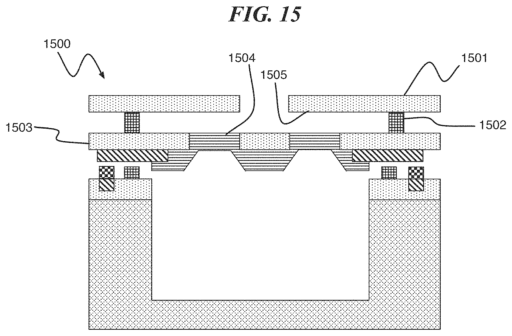
FIG. 15 is a cross section of the digital biomedical device comprising a baffle structure, according to an exemplary embodiment of the present invention; and
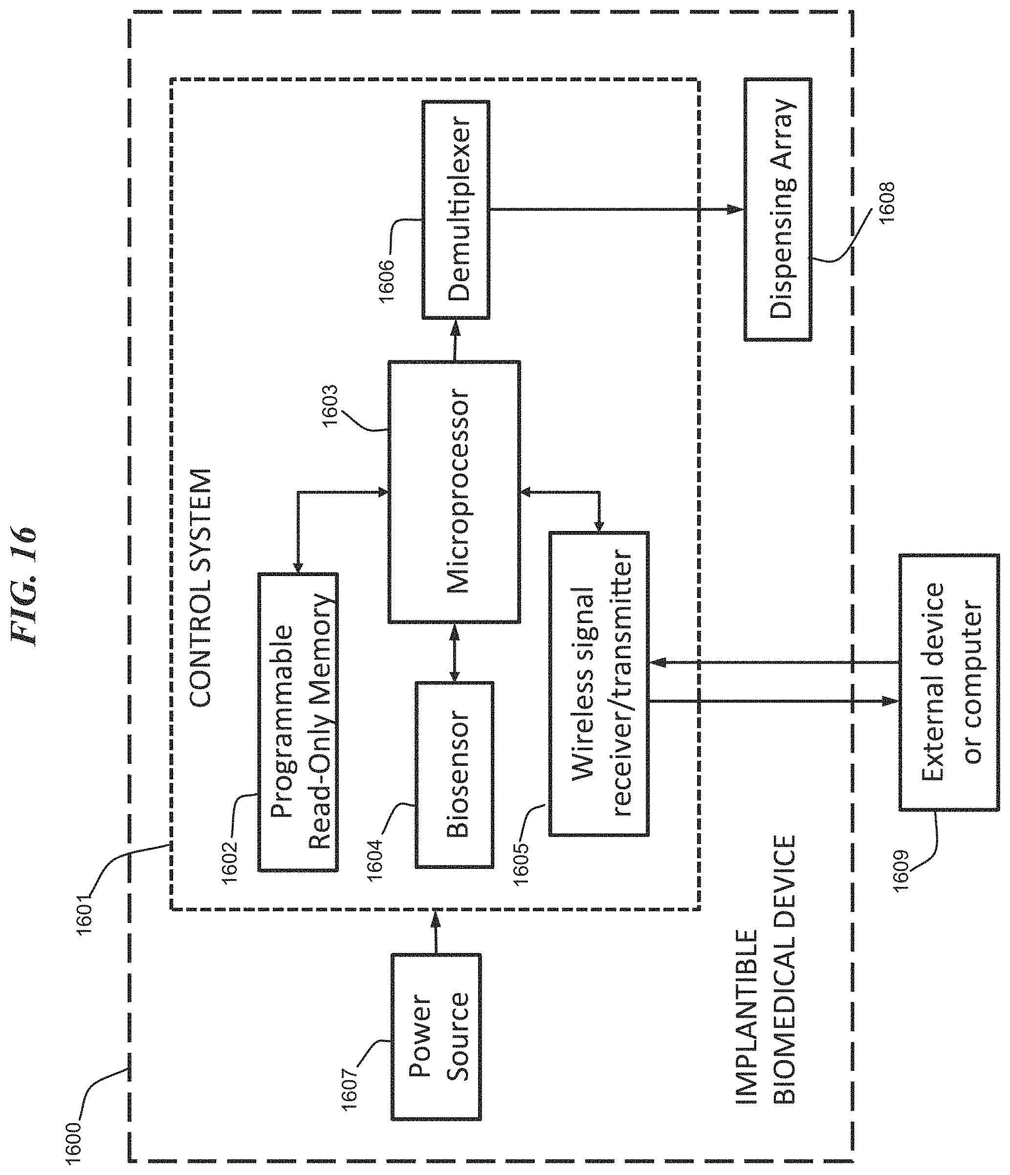
FIG. 16 is a diagram of a computer system configured to control a digital biomedical device according to an exemplary embodiment of the present invention.
DETAILED DESCRIPTION
According to an exemplary embodiment of the present invention, a digital biomedical device includes a reactive metal structure, wherein the digital biomedical device is configured to be activated, initiating a reaction of the reactive metal structure at low temperature and with low energy. According to an exemplary embodiment of the present invention, the digital biomedical device comprises a plurality of discrete, electronically-addressable structures (e.g., cavities or reservoirs). The electronically-addressable structures can be disposed in an array.
In one or more embodiments, the digital biomedical device includes a plurality of reservoirs containing a substance, such as an active agent, chemical or medication, which can be controllably released. In other embodiments, the digital biomedical device includes a plurality of cavities containing sensors for chemical activation or exposure. Each electronically-addressable structure is sealed with an electrically activated membrane or lid structure. The membrane or lid structure can be partially or completely opened under the control of the digital biomedical device.
FIG. 1 shows a delivery device 100 comprising reactive material based releasable seal according to one or more embodiments of the present invention. The delivery device 100 includes a substrate 101 having a cavity 102, a seal 103 and a lid 104. The seal 103 can be formed of a solder, oxide bonding or a polymer adhesive. A substance, such as an active agent 105, can be held in the cavity 102. According to at least one embodiment of the present invention, the seal 103 adheres the lid 104 to the substrate 101, thereby isolating the contents of the electronically-addressable structures (e.g., reservoirs) from the surrounding environment.
According to one or more embodiments of the present invention, the mechanism for releasing the contents of the cavity 102 depends on an implementation of a reactive material. For example, in one exemplary embodiment, the lid 104 includes a membrane formed of a reactive material. In another exemplary embodiment the lid 104 is released when a reactive material compromises the integrity of the seal 103. These and other embodiments are described herein.
In at least one embodiment of the present invention, the lid 104 is tethered in a stressed state (e.g., see FIG. 4). In another embodiment, the lid 104 is a non-tethered flat releasable structure (e.g., see FIG. 2). The type of lid can depend on the application, for example, for use in vivo the lid 104 is formed of a bio-compatible and/or bio-degradable materials.
Ignition of the reactive material can be initiated via a resistive heater, a high current density electric pulse, etc. In at least one embodiment of the present invention, the active agent 105 is released when a membrane is melted by the heat of reaction in the reactive material. In at least one embodiment of the present invention, the lid 104 is released upon activation of the delivery device and a phase change of the reactive material. In at least one embodiment, the phase change occurs without melting and/or vaporizing the membrane. In at least one embodiment, the phase change results in a change in membrane density, thereby introducing/relieving stress in the lid 104. In at least one embodiment, stress in the lid 104 is relieved with the formation of cracks that allow the active agent 105 to permeate a membrane component of the lid 104 and exit the delivery device 100. In another embodiment, as determined by the design of the structure, stress in the lid 104 is relieved by strain and shear (e.g., delamination) of an interface between a membrane component of the lid 104 and the seal 103, or by shear of the interface between the seal 103 and the substrate 101 including a membrane formed of a reactive material.
It should be understood that the lid structure is an overall structure, which encloses the cavity. Furthermore, the lid can include the membrane formed of the reactive material. In at least one embodiment, the membrane includes a reactive metal structure and is formed as a component of a substrate disposed adjacent to a seal.
FIG. 2 shows a layered structure 200 for connecting the lid 104 to the substrate 101. A first layer 201, comprising a metal or adhesion layer, is formed on the lid 104. A second layer 202 (e.g., a solder, polymer or oxide) is formed on the first layer 201. A first metal or adhesion layer 203, a reactive material layer 204, an insulator layer 205 (e.g., silicon dioxide (SiO.sub.2)) and a second a second solder or adhesion layer 206 are sequentially formed on the substrate 101, which can be a silicon (Si) substrate. According to an exemplary embodiment of the present invention, the insulator layer 205 restricts heat flow from the reactive material layer 204 into the lid 104, or in the case of electrical activation, restricts an electrical current from flowing into the lid 104. In at least one embodiment, if sufficient heat is generated in activation of the reactive material 204, such that heat loss into the lid 104 does not prevent self-propagation of the reaction in layer 204, then insulator layer 205 can be omitted.
The digital biomedical device according to an embodiment of the present invention is configured for controlled-release of the active agent. Controlled release can refer to a release time of the active agent, a release rate, or both. In at least one embodiment of the present invention, the controlled release is a sustained/continuous release of the active agent over a period of time (e.g., one hour, 12, hours, multiple days). Such a controlled release can be applied for cancer treatment, pain management, hypertension, angina, etc. In one or more embodiments of the present invention, the controlled release is a pulsatile release of discrete amounts of drug at variable time intervals. Such a controlled release can be applied for delivery of an active agent that mimics the way the body produces some compounds like growth hormone and insulin.
According to an exemplary embodiment of the present invention, a reactive metal material includes two or more alternating dissimilar layers of metallic elements. Table 1 shows exemplary combinations of layers to form a reactive material.
TABLE-US-00001 TABLE 1 Adiabatic State of Heat of Reaction Reactants T.sub.max (.degree. C.) Product (cal/g) (cal/cc) Si + 2B 230 Solid 76.4 177 Cu + Pd 600 Solid 44.5 472 Al + Ti 1324 Solid 240 872 Si + Co 1460 Solid-Liquid 299 1450 Al + Ni 1638 Solid 330 1710 Al + Pt 2800 Liquid 216 2510 Al + Pd 2380 Liquid 327 2890
Known methods for forming the layers of reactive metals can be used. These include rolling thick laminated layers into thin sheets, evaporation or sputtering of thin film layers onto a substrate, etc. For a suitable combination of materials, layer thickness and structure, the metals undergo an exothermic, self-propagating reaction upon application of a stimulus. To enable a reaction with good energy release and self-propagation, the layers are formed with low or no intermixing or diffusion between layers during fabrication. According to an embodiment of the present invention, the layers are thin, without being intermixed, to reduce the energy needed to initiate a reaction. According to an embodiment of the present invention, for typical deposition technologies, the thickness of the individual layers is between about 5 nanometers (nm) and 50 nm, and preferably greater than about 10 nm to avoid intermixing and reaction during layer deposition. The reactive metal material reaction can be initiated by electrical, magnetic, optical, thermal or mechanical means. For example, in at least one embodiment, the reactive metal material is heated by passing an electric current through a heater electrode disposed in close proximity to the reactive metal. In another example, the electric current is passed through the reactive metal itself. In yet another example, external methods of heating can be used including inductive heating, radiative heating, and mechanical shock. The dependence of ignition energy on layer thickness for the reactive material system aluminum (Al)+nickel (Ni) was studied by Fritz et al. (J. Applied Physics 113, 014901 (2013)), and a thermal ignition temperature as low as 232.degree. C. was obtained for a bilayer thickness of 30 nm.
In the exemplary case of a reactive material formed of Al and palladium (Pd), the reaction is about 3 times larger than the energy needed to bring the individual components up to a melting temperature of the alloy, or to melt the alloy itself. Since the ignition temperature is relatively low, the ignition energy can be about 5-10 times smaller than that needed to melt the structure, assuming uniform heating of the entire structure.
In the case that the reactive materials Al and Pd are thermally isolated, only about 1% of the volume of material needs to be heated to the ignition temperature to initiate a self-propagating reaction. With localized heating, the ignition energy can be about 500-1000 times less than that needed to melt the components of the structure. Assuming 1% volume heating, the released energy can be in the range 1500-3000 times larger than the ignition energy.
According to an exemplary embodiment of the present invention, the membrane is an activated porous membrane structure. The activated porous membrane structure is a composite structure including two or more components. At least a first component is a mechanical support structure. In one or more embodiments, the mechanical support structure is an insulating material, such as SiO.sub.2 or silicon nitride (SiNx). In one or more embodiments, the mechanical support structure includes multiple vias. According to at least one embodiment of the present invention, the vias are filled or sealed with a second component comprising a reactive metal material. According to at least one embodiment of the present invention, upon activation, the reactive metal material is compromised (e.g., melted, removed, opened, permeated, etc.), while the support structure remains intact. After activation, the membrane allows a substance to pass (e.g., a medication or chemical), and/or exposes a sensor contained within an underlying structure to the surrounding environment.
A digital biomedical device according to an embodiment of the present invention comprises a membrane formed as a reactive metal structure and configured to initiate a reaction at low temperature with low energy needs. For example, for a certain type of lid, the electrical energy needed to open an underlying structure (i.e., compromise the reactive metal material) is less than about 1 microjoule (.mu.J).
According to at least one embodiment of the present invention, for a membrane comprising two reactive materials formed of thin layers of Al and Pd, the layers can be made to react to release about 90 kilojoule (kJ)/mole of energy. For films of 50.times.50 microns and 1 .mu.m thickness, the released heat energy for a Al+Pd structure would be about 30 .mu.J. This energy is larger than that needed to melt the individual components under adiabatic conditions (about 12 .mu.J), or that needed to melt an AlPd alloy (about 12.7 .mu.J).
According to at least one embodiment of the present invention, the energy needed to heat an entire Al+Pd membrane with dimensions 50.times.50.times.1 micrometer (.mu.m) to an ignition temperature of 250.degree. C. is about 1.8 .mu.J. Additionally, the Al+Pd membrane can be locally triggered, which substantially reduces a total energy needed to start the reaction. According to at least one embodiment of the present invention, the reaction continues in a self-propagation manner until the Al and Pd reactants are consumed and the stored chemical energy is released.
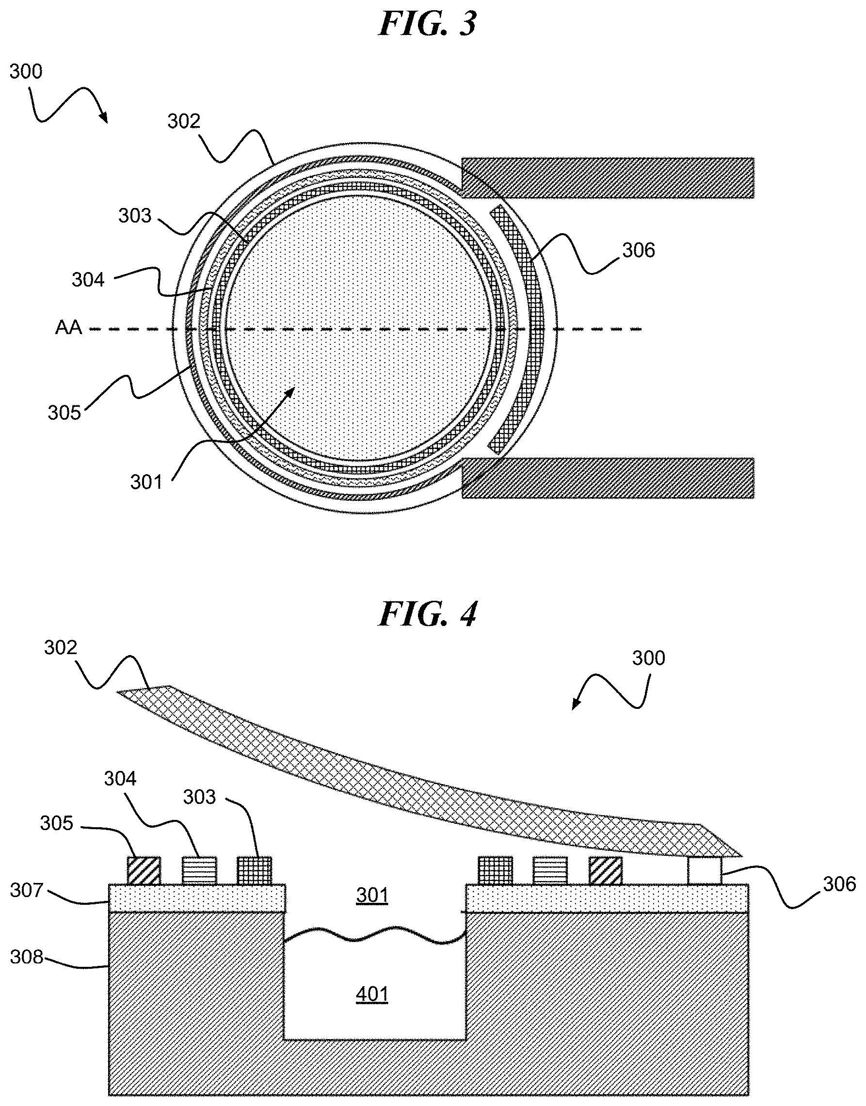
Referring to FIG. 3, a digital biomedical device 300 according to an embodiment of the present invention includes a cavity 301 surrounded by a stressed lid 302 enveloping a cavity seal 303, reactive metal layers 304, heater electrode 305 and hinge 306. The cavity 301 is formed in a substrate formed of, for example, a first layer 307 of SiO.sub.2 formed on a second layer 308 of Si.
The release of the cavity seal 303 can be initiated by heat generated by the heater electrode 305 initiating and propagating an exothermic reaction in layer 304. In at least one embodiment, the heat generated from heater electrode 305 and reactive metal layers 304 combine to melt or degrade the cavity seal 303, thereby releasing the stressed lid 302. In a suitably-designed structure, the heat is substantially confined to the region containing the reactive metal layers 304 and cavity seal 303 such that the stressed lid 302 adhesion to the hinge structure 306 remains intact.
In at least one embodiment, the digital biomedical device is formed wherein the stressed lid 302 comprises a membrane composed of reactive material. In this case, a patterned electrode structure can be used to provide heat to the stressed lid 302 to ignite the reactive material.
FIG. 4 is a cross-section of FIG. 3 along line AA in an open state, with an active agent 401 disposed within the cavity 301. According to one or more embodiments of the present invention, the lid is a stressed structure that curls when the cavity seal 303 is opened.
According to an exemplary embodiment of the present invention, the layered structure is electrically conductive, bio-compatible and generates little or no gas during a reaction. The reactive layers can melt or fracture the cavity seal or fracture themselves. The reactive layers both get hot and undergo dimensional changes creating stress.
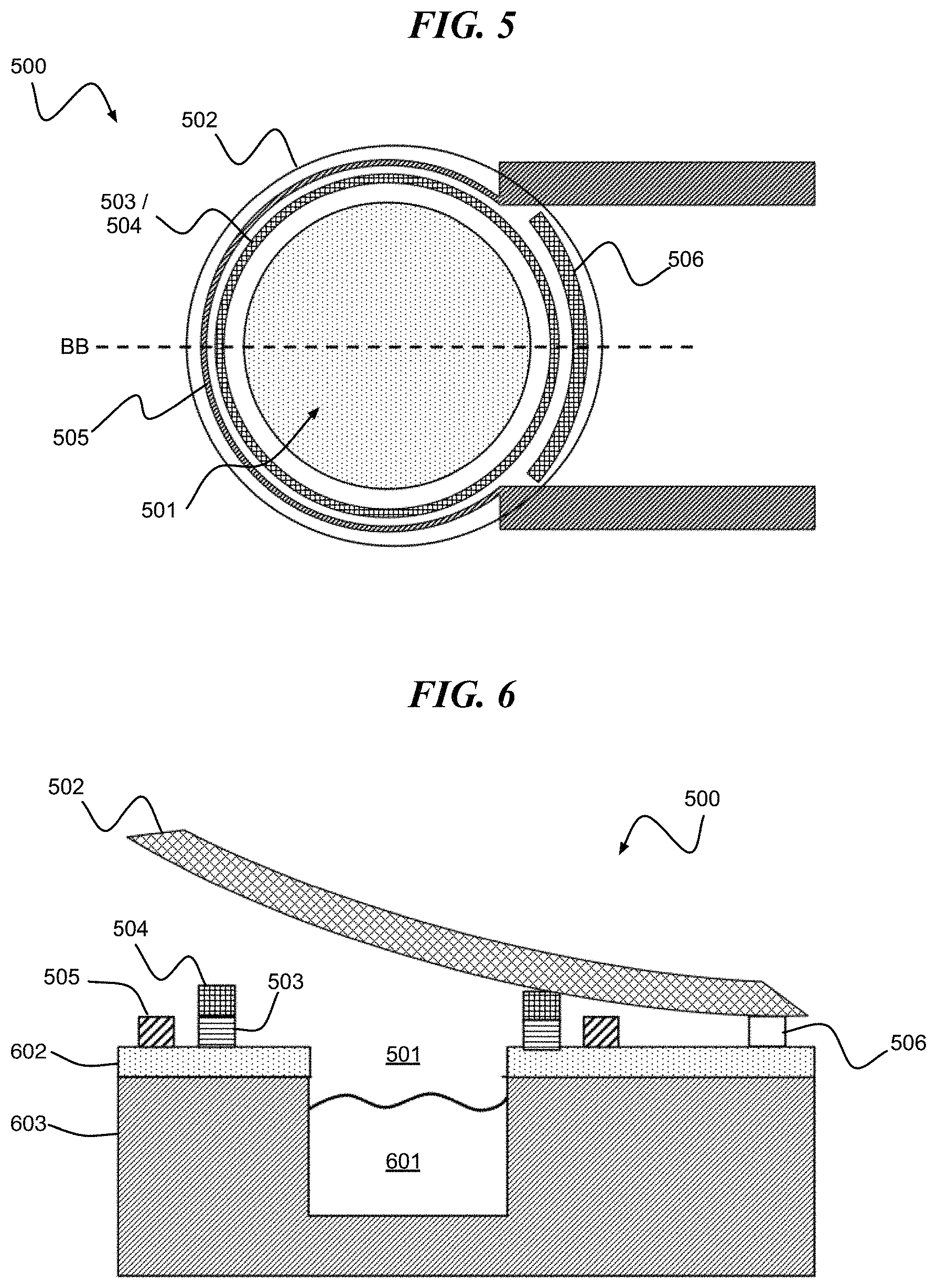
Referring to FIG. 5, a digital biomedical device 500 according to an embodiment of the present invention includes a cavity 501 surrounded by a stressed lid 502. The stressed lid 502 envelopes a composite structure including a cavity seal 503 and reactive metal layers 504. The digital biomedical device 500 further includes a heater electrode 505 and hinge 506.
FIG. 6 is a cross-section of FIG. 5 along line BB in an open state. FIG. 6 shows an active agent 601 disposed within the cavity 501. Also shown are substrate layers 602 and 603 formed of, for example, SiO.sub.2 and Si, respectively.
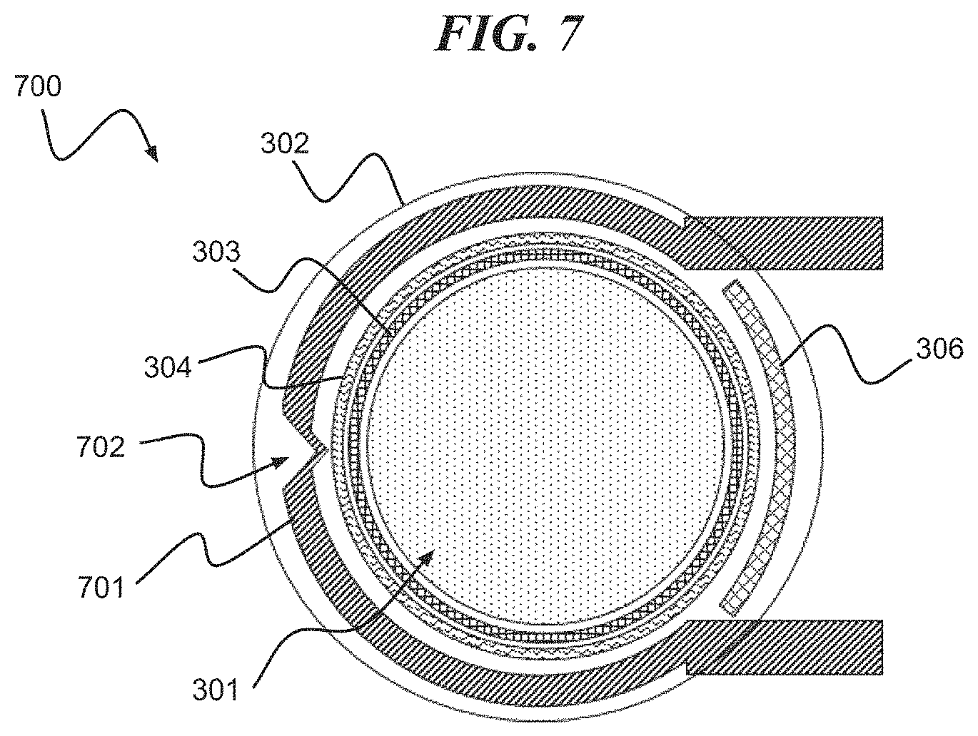
Referring to FIG. 7, a digital biomedical device 700 according to an embodiment of the present invention includes a cavity 301 surrounded by a stressed lid 302 enveloping a cavity seal 303, reactive metal layers 304, heater electrode 701 and hinge 306. The heater electrode 701 is formed including one or more shaped sections, e.g., shaped section 702, for localized heating. The shaped section 702 facilitates localized heating by, for example, having smaller surface area as compared to other sections of the heater electrode 701 or having a higher electric resistance, etc. In one embodiment of the present invention, the shaped section 702 has a v-shape. It should be understood that the shaped section 702 can have other configurations and that the present invention is not limited to a v-shaped section.
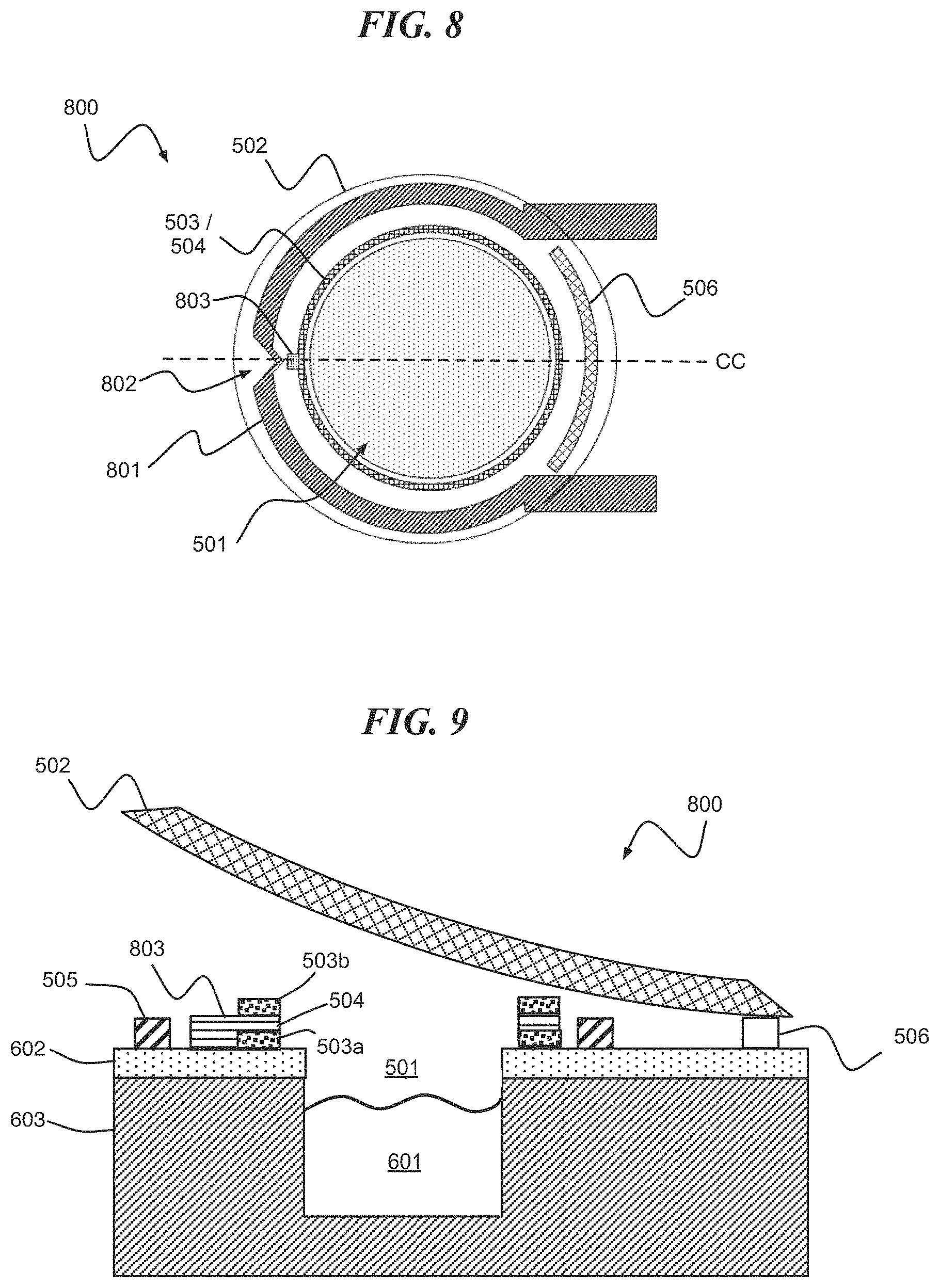
Referring to FIG. 8, a digital biomedical device 800 according to an embodiment of the present invention includes a cavity 501 surrounded by a stressed lid 502. The stressed lid 502 envelopes a composite structure including a cavity seal 503 and reactive metal layers 504. The digital biomedical device 500 further includes a heater electrode 801 and hinge 506. The heater electrode 801 is formed including one or more shaped sections, e.g., shaped section 802, for localized heating. In at least one embodiment of the present invention, a reactive metal tab 803 is disposed on the composite structure and adjacent to the shaped section 802 of the heater electrode 801. In one or more embodiments, the reactive metal tab 803 facilitates local ignition of the reactive metal layers 504 of the composite structure.
FIG. 9 is a cross-section of FIG. 8 along line CC in an open state. FIG. 9 shows an active agent 601 disposed within the cavity 501, and the composite structure including first and second cavity seals 503a and 503b having the reactive metal layers 504 disposed there between. Also shown is the reactive metal tab 803. The reactive metal layers 504 can melt or fracture one or more of the cavity seals or fracture themselves, for example, when the reactive metal layers 504 heat and undergo dimensional changes creating stress.
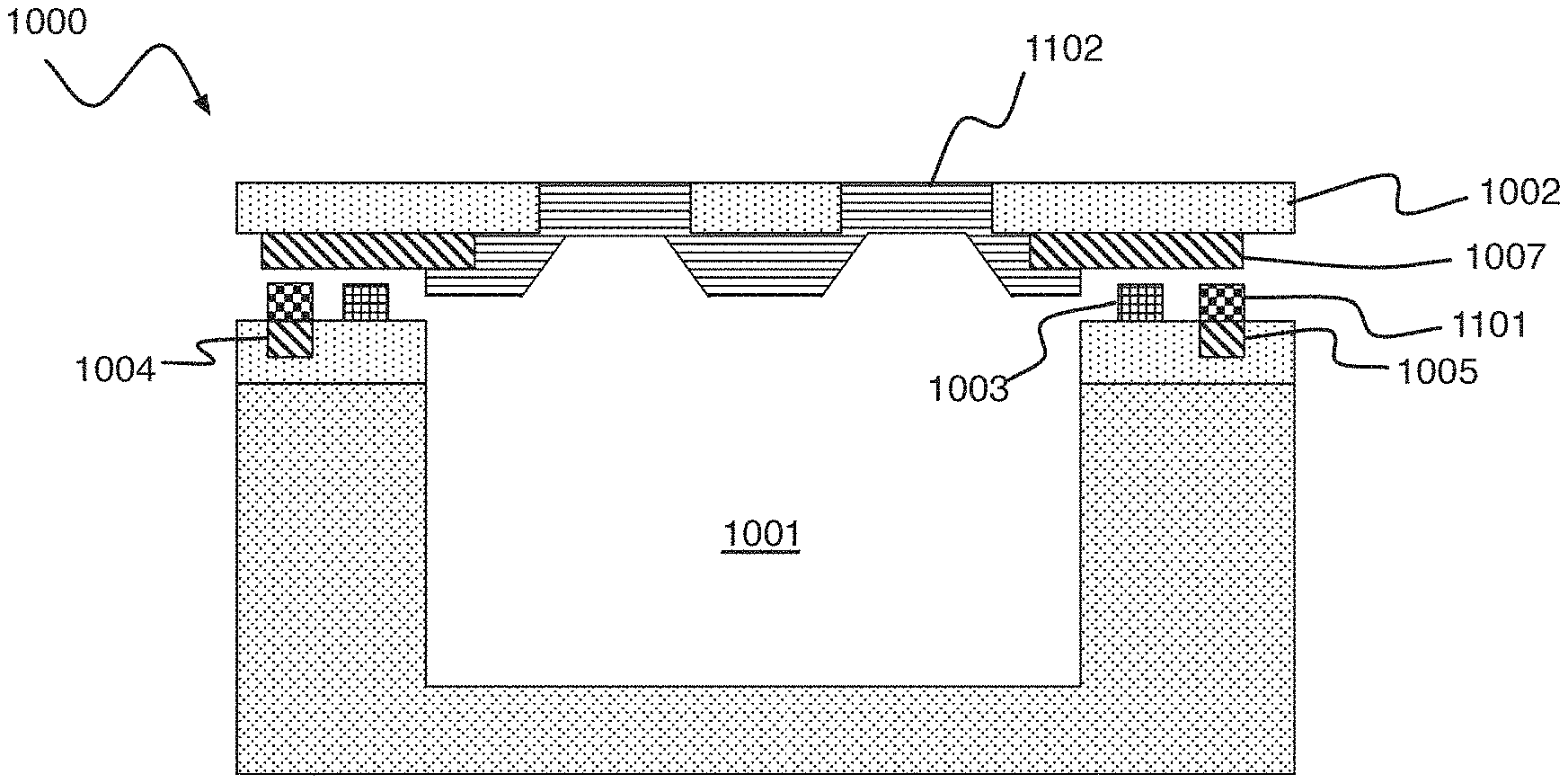
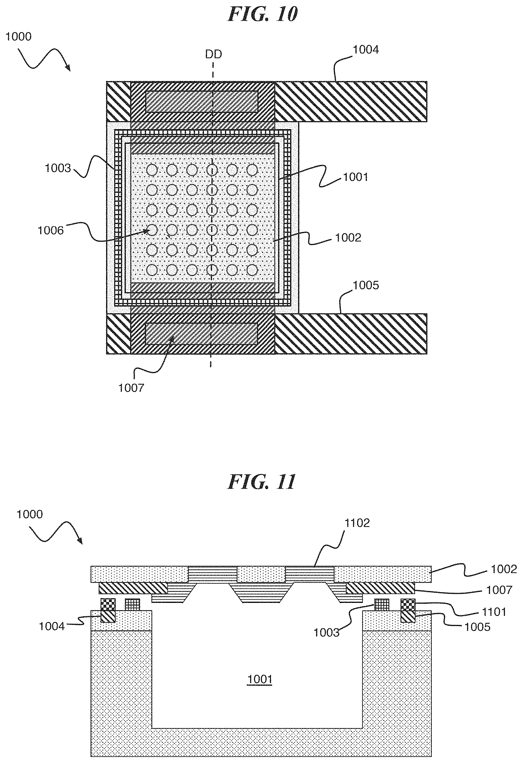
Referring to FIG. 10 and FIG. 11, a digital biomedical device 1000 according to an embodiment of the present invention includes a cavity 1001 disposed under a composite lid structure comprised of a support structure 1002 and reactive metal membrane 1102. The support structure 1002 material is an electrical and thermal insulator with vias 1006 that are filled with the reactive metal membrane 1102 material. The composite lid structure is connected to a substrate (implied but not shown) by a cavity seal 1003 (e.g., an organic seal). The composite lid structure is disposed between a pair of metal traces 1004 and 1005, e.g., formed on Cu. The composite lid structure includes a metal trace 1007 connecting the reactive metal layer 1102 to the pair of metal traces 1004 and 1005 on the substrate. The composite lid structure can be compromised (e.g., to form a porous structure) by passing a current between the pair of metal traces 1004 and 1005 and through the reactive metal layer 1102. The current causes reactive metal layer 1102 to melt or vaporize, thereby clearing the vias 1006 in the support structure 1002.
FIG. 11 is a simplified cross-section of FIG. 10 along line DD, showing the cavity 1001, reactive metal membrane 1002 and cavity seal 1003. Also shown are metal traces 1004, 1005, and 1007. While an air gap is shown in FIG. 11, the cavity seal 1003 makes mechanical contact and forms a hermetic seal to both membrane 1002 and metal trace 1007. A solder 1101 can be used to make electrical connection between the metal traces 1004 and 1005 (e.g., formed of Cu) to the metal trace 1007 of the composite lid structure.
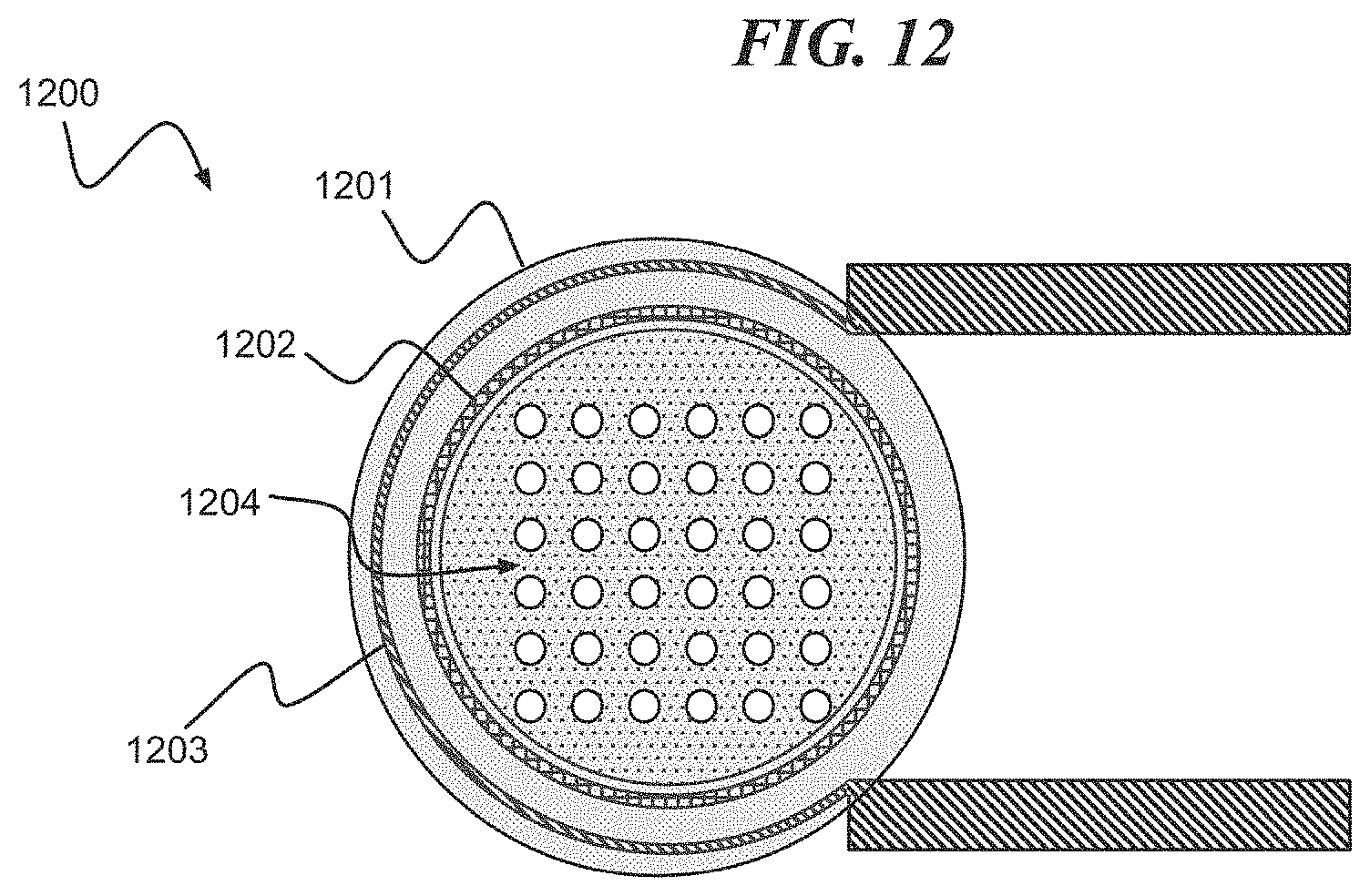
Referring to FIG. 12, a digital biomedical device 1200 according to an embodiment of the present invention includes a cavity (implied by not shown) disposed under a lid including a reactive metal membrane 1201. The digital biomedical device 1200 includes a cavity seal 1202 sealing the lid including the reactive metal membrane 1201 to a substrate. The digital biomedical device 1200 further includes a heater electrode 1203. FIG. 12 is depicted with a porous membrane 1204 of the lid including the reactive metal membrane 1201 exposing the cavity below after a reaction.
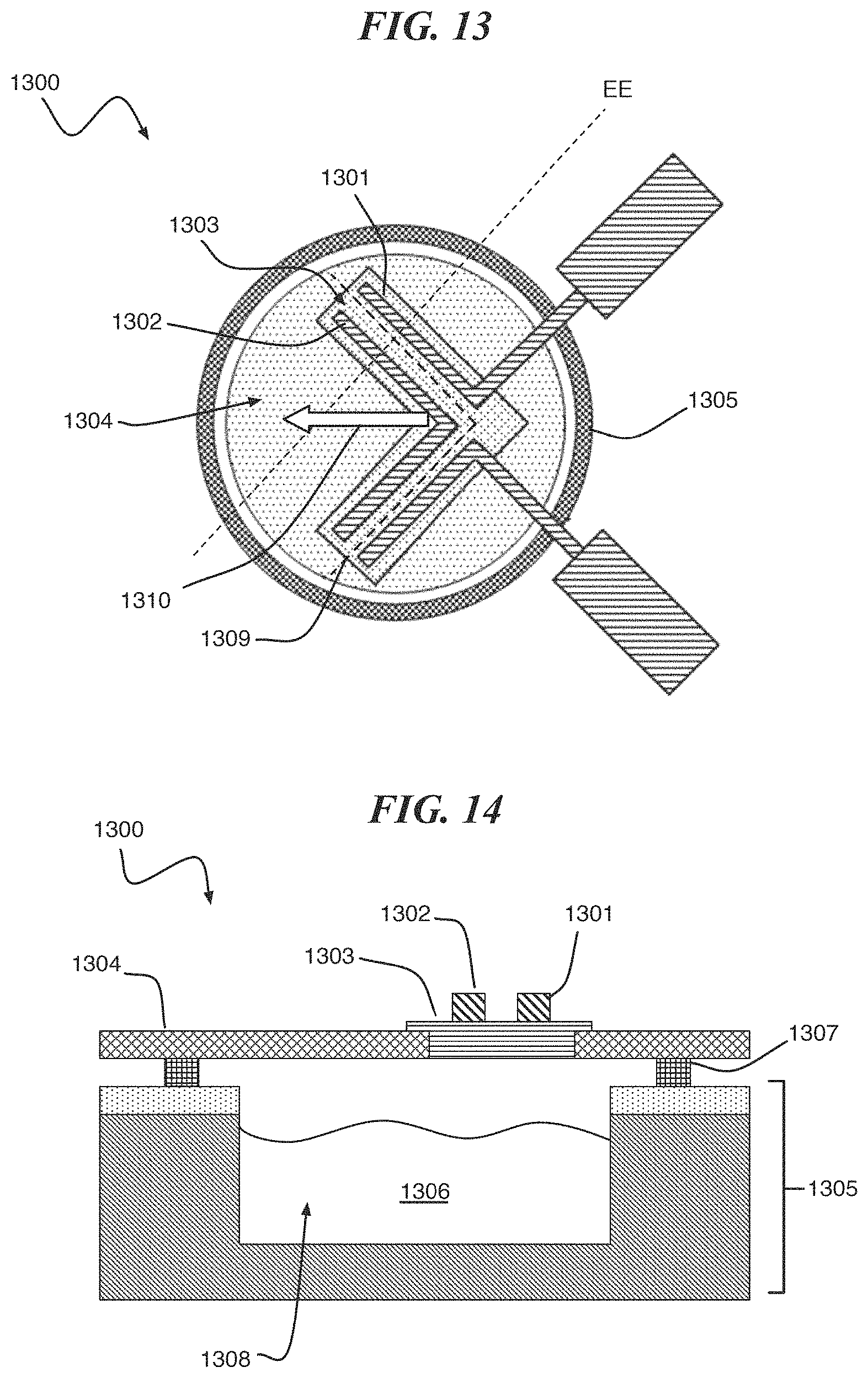
FIG. 13, according to one or more embodiments of the present invention, a digital biomedical device 1300 comprises a plurality of metal traces 1301, 1302 disposed on a reactive metal structure 1303. The reactive metal structure 1303 is a component of a lid including a stressed insulator membrane 1304. The lid including the stressed insulator membrane 1304 is connected to a substrate 1305 including a cavity 1306 by a cavity seal 1307 (see FIG. 14). FIG. 14 is a cross-sectional view of the structure shown in FIG. 13 showing an active agent 1308 disposed within the cavity 1306. According to an embodiment of the present invention, the reactive metal structure 1303 ruptures upon application of a current to the metal traces, facilitating the opening of the lid including the stressed insulator membrane 1304. The rupture occurs in reactive metal structure 1303, between metal electrode structures 1301 and 1302, making a V-shaped cut in the lid including the membrane 1304 along dotted line 1309, with the stressed insulator membrane pealing in the direction of arrow 1310. The stress in the lid including the membrane 1304 is released upon the formation of the V-shaped cut by allowing the V-shaped region to peel back from the rest of the membrane structure.
In one or more embodiments of the present invention, a baffle structure comprising a baffle 1501 and a spacer 1502 is formed on a lid 1503 including a composite membrane 1504 of a digital biomedical device 1500 as shown in FIG. 15. The baffle structure controls a path of an active agent and collects residual reactive metal on a lower surface 1505.
Exemplary embodiments of the present invention can be associated with a variety of improvements including placement of the device at/near a treatment site, delivery on demand (e.g., emergency administration, pulsatile, adjustable continuous), automated delivery of single/multiple active agents and dosing in response to physiological and diagnostic feedback, patient compliance, low impact on patient lifestyle, low power parameters (e.g., current, ignition temperature), and small onboard power supply or wireless power parameters.
The methodologies of embodiments of the disclosure may be particularly well-suited for use in an electronic device or alternative system. Accordingly, embodiments of the present invention may take the form of an entirely hardware embodiment or an embodiment combining software and hardware aspects that may all generally be referred to herein as a "processor," "circuit," "module" or "system."
Furthermore, it should be noted that any of the methods described herein can include an additional step of providing a digital biomedical device including a reactive metal structure. Further, a computer program product can include a tangible computer-readable recordable storage medium with code adapted to be executed to carry out one or more method steps described herein, including the provision of the system with the distinct software modules.
Referring to FIG. 16; FIG. 16 is a block diagram depicting an exemplary computer system embodying the digital biomedical device 1600 according to an embodiment of the present invention. The computer system shown in FIG. 16 includes a control system 1601 having a memory 1602, a processor 1603, at least one sensor 1604, a communications device 1605 and an input/output device 1606. The control system 1601 is connected to a power supply 1607, a dispensing array 1608 and optionally, an external device or computer 1609.
In different applications, some of the components shown in FIG. 16 can be omitted. The whole system shown in FIG. 16 is controlled by computer readable instructions, which are generally stored in the memory 1602. The software can be downloaded from a network (not shown in the figures), stored in the memory 1602. Alternatively, software downloaded from a network (e.g., 1609) can be loaded into the memory 1602 and executed by the processor 1603 so as to complete the function determined by the software.
The processor 1603 may be configured to perform one or more methodologies described in the present disclosure, illustrative embodiments of which are shown in the above figures and described herein. Embodiments of the present invention can be implemented as a routine that is stored in memory 1602 and executed by the processor 1603 to process the signal from the sensor 1604. As such, the computer system is a general-purpose computer system that becomes a specific purpose computer system when executing routines of the present disclosure.
Although the computer system described in FIG. 16 can support methods according to the present disclosure, this system is only one example of a computer system. Those skilled of the art should understand that other computer system designs can be used to implement embodiments of the present invention.
The present invention may be a system, a method, and/or a computer program product. The computer program product may include a computer readable storage medium (or media) having computer readable program instructions thereon for causing a processor to carry out aspects of the present invention.
The computer readable storage medium can be a tangible device that can retain and store instructions for use by an instruction execution device. The computer readable storage medium may be, for example, but is not limited to, an electronic storage device, a magnetic storage device, an optical storage device, an electromagnetic storage device, a semiconductor storage device, or any suitable combination of the foregoing. A non-exhaustive list of more specific examples of the computer readable storage medium includes the following: a portable computer diskette, a hard disk, a random access memory (RAM), a read-only memory (ROM), an erasable programmable read-only memory (EPROM or Flash memory), a static random access memory (SRAM), a portable compact disc read-only memory (CD-ROM), a digital versatile disk (DVD), a memory stick, a floppy disk, a mechanically encoded device such as punch-cards or raised structures in a groove having instructions recorded thereon, and any suitable combination of the foregoing. A computer readable storage medium, as used herein, is not to be construed as being transitory signals per se, such as radio waves or other freely propagating electromagnetic waves, electromagnetic waves propagating through a waveguide or other transmission media (e.g., light pulses passing through a fiber-optic cable), or electrical signals transmitted through a wire.
Computer readable program instructions described herein can be downloaded to respective computing/processing devices from a computer readable storage medium or to an external computer or external storage device via a network, for example, the Internet, a local area network, a wide area network and/or a wireless network. The network may comprise copper transmission cables, optical transmission fibers, wireless transmission, routers, firewalls, switches, gateway computers and/or edge servers. A network adapter card or network interface in each computing/processing device receives computer readable program instructions from the network and forwards the computer readable program instructions for storage in a computer readable storage medium within the respective computing/processing device.
Computer readable program instructions for carrying out operations of the present invention may be assembler instructions, instruction-set-architecture (ISA) instructions, machine instructions, machine dependent instructions, microcode, firmware instructions, state-setting data, or either source code or object code written in any combination of one or more programming languages, including an object oriented programming language such as Smalltalk, C++ or the like, and conventional procedural programming languages, such as the "C" programming language or similar programming languages. The computer readable program instructions may execute entirely on the user's computer, partly on the user's computer, as a stand-alone software package, partly on the user's computer and partly on a remote computer or entirely on the remote computer or server. In the latter scenario, the remote computer may be connected to the user's computer through any type of network, including a local area network (LAN) or a wide area network (WAN), or the connection may be made to an external computer (for example, through the Internet using an Internet Service Provider). In some embodiments, electronic circuitry including, for example, programmable logic circuitry, field-programmable gate arrays (FPGA), or programmable logic arrays (PLA) may execute the computer readable program instructions by utilizing state information of the computer readable program instructions to personalize the electronic circuitry, in order to perform aspects of the present invention.
Aspects of the present invention are described herein with reference to flowchart illustrations and/or block diagrams of methods, apparatus (systems), and computer program products according to embodiments of the invention. It will be understood that each block of the flowchart illustrations and/or block diagrams, and combinations of blocks in the flowchart illustrations and/or block diagrams, can be implemented by computer readable program instructions.
These computer readable program instructions may be provided to a processor of a general purpose computer, special purpose computer, or other programmable data processing apparatus to produce a machine, such that the instructions, which execute via the processor of the computer or other programmable data processing apparatus, create means for implementing the functions/acts specified in the flowchart and/or block diagram block or blocks. These computer readable program instructions may also be stored in a computer readable storage medium that can direct a computer, a programmable data processing apparatus, and/or other devices to function in a particular manner, such that the computer readable storage medium having instructions stored therein comprises an article of manufacture including instructions which implement aspects of the function/act specified in the flowchart and/or block diagram block or blocks.
The computer readable program instructions may also be loaded onto a computer, other programmable data processing apparatus, or other device to cause a series of operational steps to be performed on the computer, other programmable apparatus or other device to produce a computer implemented process, such that the instructions which execute on the computer, other programmable apparatus, or other device implement the functions/acts specified in the flowchart and/or block diagram block or blocks.
The flowchart and block diagrams in the Figures illustrate the architecture, functionality, and operation of possible implementations of systems, methods, and computer program products according to various embodiments of the present invention. In this regard, each block in the flowchart or block diagrams may represent a module, segment, or portion of instructions, which comprises one or more executable instructions for implementing the specified logical function(s). In some alternative implementations, the functions noted in the block may occur out of the order noted in the figures. For example, two blocks shown in succession may, in fact, be executed substantially concurrently, or the blocks may sometimes be executed in the reverse order, depending upon the functionality involved. It will also be noted that each block of the block diagrams and/or flowchart illustration, and combinations of blocks in the block diagrams and/or flowchart illustration, can be implemented by special purpose hardware-based systems that perform the specified functions or acts or carry out combinations of special purpose hardware and computer instructions.
The terminology used herein is for the purpose of describing particular embodiments only and is not intended to be limiting of the invention. As used herein, the singular forms "a", "an" and "the" are intended to include the plural forms as well, unless the context clearly indicates otherwise. It will be further understood that the terms "comprises" and/or "comprising," when used in this specification, specify the presence of stated features, integers, steps, operations, elements, and/or components, but do not preclude the presence or addition of one or more other features, integers, steps, operations, elements, components, and/or groups thereof.
The corresponding structures, materials, acts, and equivalents of all means or step plus function elements in the claims below are intended to include any structure, material, or act for performing the function in combination with other claimed elements as specifically claimed. The description of the present invention has been presented for purposes of illustration and description, but is not intended to be exhaustive or limited to the invention in the form disclosed. Many modifications and variations will be apparent to those of ordinary skill in the art without departing from the scope and spirit of the invention. The embodiment was chosen and described in order to best explain the principles of the invention and the practical application, and to enable others of ordinary skill in the art to understand the invention for various embodiments with various modifications as are suited to the particular use contemplated.
* * * * *
References
D00000
D00001
D00002
D00003
D00004
D00005
D00006
D00007
D00008
D00009
D00010
XML
uspto.report is an independent third-party trademark research tool that is not affiliated, endorsed, or sponsored by the United States Patent and Trademark Office (USPTO) or any other governmental organization. The information provided by uspto.report is based on publicly available data at the time of writing and is intended for informational purposes only.
While we strive to provide accurate and up-to-date information, we do not guarantee the accuracy, completeness, reliability, or suitability of the information displayed on this site. The use of this site is at your own risk. Any reliance you place on such information is therefore strictly at your own risk.
All official trademark data, including owner information, should be verified by visiting the official USPTO website at www.uspto.gov. This site is not intended to replace professional legal advice and should not be used as a substitute for consulting with a legal professional who is knowledgeable about trademark law.