Method and apparatus for applying a knot to a suture
Nobles , et al. Sep
U.S. patent number 10,758,223 [Application Number 15/586,397] was granted by the patent office on 2020-09-01 for method and apparatus for applying a knot to a suture. This patent grant is currently assigned to Scarab Technology Services, LLC. The grantee listed for this patent is Scarab Technology Services, LLC. Invention is credited to Steven E. Decker, Anthony A. Nobles, Egbert Ratering.
View All Diagrams
| United States Patent | 10,758,223 |
| Nobles , et al. | September 1, 2020 |
Method and apparatus for applying a knot to a suture
Abstract
A knot placement device allows a physician to apply a knot for securing two or more suture ends extending from an incision in a vessel or organ of a patient relative to each other in order to seal an opening in the vessel or organ. The knot placement device has a handle and an elongate shaft and a push rod slidably inserted in said shaft. A knot is disposed in the distal end of the shaft. An actuator on the handle may be depressed to distally advance said push rod relative to said shaft and thereby distally advance said knot. The knot may include a knot body having an inner cavity and a plug sized to fit securely within the inner cavity. In use, the plug may be inserted into the inner cavity of the knot body to fixedly hold two or more suture ends between the knot body and the plug.
| Inventors: | Nobles; Anthony A. (Fountain Valley, CA), Decker; Steven E. (Anaheim, CA), Ratering; Egbert (Amsterdam, NL) | ||||||||||
|---|---|---|---|---|---|---|---|---|---|---|---|
| Applicant: |
|
||||||||||
| Assignee: | Scarab Technology Services, LLC
(St. Thomas, VG) |
||||||||||
| Family ID: | 37309583 | ||||||||||
| Appl. No.: | 15/586,397 | ||||||||||
| Filed: | May 4, 2017 |
Prior Publication Data
| Document Identifier | Publication Date | |
|---|---|---|
| US 20170319199 A1 | Nov 9, 2017 | |
Related U.S. Patent Documents
| Application Number | Filing Date | Patent Number | Issue Date | ||
|---|---|---|---|---|---|
| 13905225 | May 30, 2013 | 9642616 | |||
| 13489573 | Jun 25, 2013 | 8469975 | |||
| 11455894 | Jun 12, 2012 | 8197497 | |||
| 60693582 | Jun 20, 2005 | ||||
| 60709485 | Aug 19, 2005 | ||||
| Current U.S. Class: | 1/1 |
| Current CPC Class: | A61B 17/0487 (20130101); A61B 17/0491 (20130101); A61B 17/0485 (20130101); A61B 17/0467 (20130101); A61B 2017/045 (20130101); A61B 17/0469 (20130101); A61B 2017/0459 (20130101); A61B 2017/0488 (20130101) |
| Current International Class: | A61B 17/04 (20060101) |
References Cited [Referenced By]
U.S. Patent Documents
| 118683 | September 1871 | Bruce |
| 1064307 | June 1913 | Fleming |
| 1822330 | September 1931 | Ainslie |
| 1989919 | February 1935 | Everitt |
| 2348218 | May 1944 | Karle |
| 2473742 | June 1949 | Auzin |
| 2548602 | April 1951 | Greenburg |
| 2637290 | May 1953 | Sigoda |
| 2738790 | March 1956 | Todt, Sr. et al. |
| 2849002 | August 1958 | Oddo |
| 2945460 | July 1960 | Kagiyama |
| 3241554 | March 1966 | Coanda |
| 3292627 | December 1966 | Harautuneian |
| 3394705 | July 1968 | Abramson |
| 3664345 | May 1972 | Dabbs et al. |
| 3665926 | May 1972 | Flores |
| 3774596 | November 1973 | Cook |
| 3828790 | August 1974 | Curtiss et al. |
| 3831587 | August 1974 | Boyd |
| 3842840 | October 1974 | Schweizer |
| 3877434 | April 1975 | Ferguson et al. |
| 3882852 | May 1975 | Sinnreich |
| 3882855 | May 1975 | Schulte et al. |
| 3888117 | June 1975 | Lewis |
| 3903893 | September 1975 | Scheer |
| 3946740 | March 1976 | Bassett |
| 3946741 | March 1976 | Adair |
| 3952742 | April 1976 | Taylor |
| 3976079 | August 1976 | Samuels |
| 4052980 | October 1977 | Grams et al. |
| RE29703 | July 1978 | Fatt |
| 4107953 | August 1978 | Casillo |
| 4119100 | October 1978 | Rickett |
| 4164225 | August 1979 | Johnson et al. |
| 4230119 | October 1980 | Blum |
| 4291698 | September 1981 | Fuchs et al. |
| 4299237 | November 1981 | Foti |
| 4307722 | December 1981 | Evans |
| 4345601 | August 1982 | Fukuda |
| 4351342 | September 1982 | Wiita et al. |
| 4417532 | November 1983 | Yasukata |
| 4423725 | January 1984 | Baran et al. |
| 4447227 | May 1984 | Kotsanis |
| 4457300 | July 1984 | Budde |
| 4484580 | November 1984 | Nomoto et al. |
| 4512338 | April 1985 | Balko et al. |
| 4546759 | October 1985 | Solar |
| 4553543 | November 1985 | Amarasinghe |
| 4573966 | March 1986 | Weikl et al. |
| 4589868 | May 1986 | Dretler |
| 4610662 | September 1986 | Weikl et al. |
| 4617738 | October 1986 | Kopacz |
| 4662068 | May 1987 | Polonsky |
| 4664114 | May 1987 | Ghodsian |
| 4734094 | March 1988 | Jacob et al. |
| 4744364 | May 1988 | Kensey |
| 4750492 | June 1988 | Jacobs |
| 4771776 | September 1988 | Powell et al. |
| 4774091 | September 1988 | Yamahira et al. |
| 4794928 | January 1989 | Kletschka |
| 4795427 | January 1989 | Helzel |
| 4796629 | January 1989 | Grayzel |
| 4824436 | April 1989 | Wolinsky |
| 4827931 | May 1989 | Longmore |
| 4841888 | June 1989 | Mills et al. |
| 4861330 | August 1989 | Voss |
| 4898168 | February 1990 | Yule |
| 4923461 | May 1990 | Caspari et al. |
| 4926860 | May 1990 | Stice et al. |
| 4932956 | June 1990 | Reddy et al. |
| 4935027 | June 1990 | Yoon |
| 4954126 | September 1990 | Wallsten |
| 4957498 | September 1990 | Caspari et al. |
| 4972845 | November 1990 | Iversen et al. |
| 4981149 | January 1991 | Yoon et al. |
| 4983116 | January 1991 | Koga |
| 4984564 | January 1991 | Yuen |
| 4994070 | February 1991 | Waters |
| 5002531 | March 1991 | Bonzel |
| 5021059 | June 1991 | Kensey et al. |
| 5037433 | August 1991 | Wilk et al. |
| 5057114 | October 1991 | Wittich et al. |
| 5059201 | October 1991 | Asnis |
| 5065772 | November 1991 | Cox, Jr. |
| 5074871 | December 1991 | Groshong |
| 5078743 | January 1992 | Mikalov et al. |
| 5090958 | February 1992 | Sahota |
| 5100418 | March 1992 | Yoon et al. |
| 5104394 | April 1992 | Knoepfler |
| 5106363 | April 1992 | Nobuyoshi |
| 5108416 | April 1992 | Ryan et al. |
| 5108419 | April 1992 | Reger et al. |
| 5116305 | May 1992 | Milder et al. |
| 5122122 | June 1992 | Allgood |
| 5129883 | July 1992 | Black |
| 5133724 | July 1992 | Wilson et al. |
| 5135484 | August 1992 | Wright |
| 5160339 | November 1992 | Chen et al. |
| 5163906 | November 1992 | Ahmadi |
| 5167223 | December 1992 | Koros et al. |
| 5171251 | December 1992 | Bregen et al. |
| 5176691 | January 1993 | Pierce |
| 5192301 | March 1993 | Kamiya et al. |
| 5222508 | June 1993 | Contarini |
| 5222941 | June 1993 | Don Michael |
| 5222974 | June 1993 | Kensey et al. |
| 5224948 | July 1993 | Abe et al. |
| 5236443 | August 1993 | Sontag |
| 5242459 | September 1993 | Buelna |
| 5281234 | January 1994 | Wilk et al. |
| 5281237 | January 1994 | Gimpelson |
| 5282827 | February 1994 | Kensey et al. |
| 5286259 | February 1994 | Ganguly et al. |
| 5290249 | March 1994 | Foster et al. |
| 5291639 | March 1994 | Baum et al. |
| 5300106 | April 1994 | Dahl et al. |
| 5304184 | April 1994 | Hathaway et al. |
| 5308323 | May 1994 | Sogawa et al. |
| 5312344 | May 1994 | Grinfeld |
| 5314409 | May 1994 | Sarosiek et al. |
| 5320604 | June 1994 | Walker et al. |
| 5320632 | June 1994 | Heidmueller |
| 5330446 | July 1994 | Weldon et al. |
| 5330497 | July 1994 | Freitas et al. |
| 5331975 | July 1994 | Bonutti |
| 5336229 | August 1994 | Noda |
| 5336231 | August 1994 | Adair |
| 5337736 | August 1994 | Reddy |
| 5339801 | August 1994 | Poloyko |
| 5342306 | August 1994 | Don Michael |
| 5342385 | August 1994 | Norelli et al. |
| 5342393 | August 1994 | Stack |
| 5350399 | September 1994 | Erlebacher et al. |
| 5356382 | October 1994 | Picha et al. |
| 5364407 | November 1994 | Poll |
| 5364408 | November 1994 | Gordon |
| 5368601 | November 1994 | Sauer et al. |
| 5370618 | December 1994 | Leonhardt |
| 5370685 | December 1994 | Stevens |
| 5374275 | December 1994 | Bradley et al. |
| 5380284 | January 1995 | Don Michael |
| 5382261 | January 1995 | Palmaz |
| 5383854 | January 1995 | Safar et al. |
| 5383896 | January 1995 | Gershony et al. |
| 5383897 | January 1995 | Wholey |
| 5383905 | January 1995 | Golds et al. |
| 5389103 | February 1995 | Melzer et al. |
| 5391147 | February 1995 | Imran et al. |
| 5391174 | February 1995 | Weston |
| 5395383 | March 1995 | Adams et al. |
| 5397325 | March 1995 | Badia et al. |
| 5403329 | April 1995 | Hinchcliffe |
| 5403331 | April 1995 | Chesterfield et al. |
| 5403341 | April 1995 | Solar |
| 5405322 | April 1995 | Lennox et al. |
| 5405354 | April 1995 | Sarrett |
| 5417699 | May 1995 | Klein et al. |
| 5417700 | May 1995 | Egan |
| 5423777 | June 1995 | Tajiri et al. |
| 5423837 | June 1995 | Mericle et al. |
| 5425708 | June 1995 | Nasu |
| 5425737 | June 1995 | Burbank et al. |
| 5425744 | June 1995 | Fagan et al. |
| 5429118 | July 1995 | Cole et al. |
| 5431666 | July 1995 | Sauer et al. |
| 5439470 | August 1995 | Li |
| 5445167 | August 1995 | Yoon et al. |
| 5447515 | September 1995 | Robicsek |
| 5452513 | September 1995 | Zinnbauer et al. |
| 5454823 | October 1995 | Richardson et al. |
| 5458574 | October 1995 | Machold et al. |
| 5458609 | October 1995 | Gordon et al. |
| 5462560 | October 1995 | Stevens |
| 5462561 | October 1995 | Voda |
| 5470338 | November 1995 | Whitefield et al. |
| 5474572 | December 1995 | Hayburst |
| 5476469 | December 1995 | Hathaway et al. |
| 5476470 | December 1995 | Fitzgibbons, Jr. |
| 5496332 | March 1996 | Sierra et al. |
| 5499991 | March 1996 | Garman et al. |
| 5501691 | March 1996 | Goldrath |
| 5507754 | April 1996 | Green et al. |
| 5507755 | April 1996 | Gresl et al. |
| 5514159 | May 1996 | Matula et al. |
| 5520609 | May 1996 | Moll et al. |
| 5520702 | May 1996 | Sauer et al. |
| 5522961 | June 1996 | Leonhardt |
| 5527321 | June 1996 | Hinchliffe |
| 5527322 | June 1996 | Klein et al. |
| 5527338 | June 1996 | Purdy |
| 5540658 | July 1996 | Evans et al. |
| 5540704 | July 1996 | Gordon et al. |
| 5545170 | August 1996 | Hart |
| 5549633 | August 1996 | Evans et al. |
| 5558642 | September 1996 | Schweich et al. |
| 5558644 | September 1996 | Boyd et al. |
| RE35352 | October 1996 | Peters |
| 5562686 | October 1996 | Sauer et al. |
| 5562688 | October 1996 | Riza |
| 5565122 | October 1996 | Zinnbauer et al. |
| 5571090 | November 1996 | Sherts |
| 5573540 | November 1996 | Yoon |
| 5584835 | December 1996 | Greenfield |
| 5584861 | December 1996 | Swain et al. |
| 5591195 | January 1997 | Taheri et al. |
| 5593422 | January 1997 | Muijs Van de Moer et al. |
| 5599307 | February 1997 | Bacher et al. |
| 5603718 | February 1997 | Xu |
| 5613974 | March 1997 | Andreas et al. |
| 5613975 | March 1997 | Christy |
| 5626590 | May 1997 | Wilk |
| 5630833 | May 1997 | Katsaros et al. |
| 5632751 | May 1997 | Piraka |
| 5632752 | May 1997 | Buelna |
| 5634936 | June 1997 | Linden et al. |
| 5637097 | June 1997 | Yoon |
| 5643289 | July 1997 | Sauer et al. |
| 5645553 | July 1997 | Kolesa et al. |
| 5662663 | September 1997 | Shallman |
| 5669917 | September 1997 | Sauer et al. |
| 5669971 | September 1997 | Bok et al. |
| 5674198 | October 1997 | Leone |
| 5681296 | October 1997 | Ishida |
| 5681351 | October 1997 | Jamiolkowski et al. |
| 5688245 | November 1997 | Runge |
| 5690674 | November 1997 | Diaz |
| 5695468 | December 1997 | Lafontaine et al. |
| 5695504 | December 1997 | Gifford, III et al. |
| 5697905 | December 1997 | D'Amnbrosio |
| 5700273 | December 1997 | Buelna et al. |
| 5700277 | December 1997 | Nash et al. |
| 5707379 | January 1998 | Fleenor et al. |
| 5709693 | January 1998 | Taylor |
| 5716329 | February 1998 | Dieter |
| 5720757 | February 1998 | Hathaway et al. |
| 5722983 | March 1998 | Van Der Weegen |
| 5728109 | March 1998 | Schulze et al. |
| 5738629 | April 1998 | Moll et al. |
| 5743852 | April 1998 | Johnson |
| 5746753 | May 1998 | Sullivan et al. |
| 5749883 | May 1998 | Halpern |
| 5759188 | June 1998 | Yoon |
| 5766183 | June 1998 | Sauer |
| 5766220 | June 1998 | Moenning |
| 5769870 | June 1998 | Salahieh et al. |
| 5779719 | July 1998 | Klein et al. |
| 5792152 | August 1998 | Klein et al. |
| 5792153 | August 1998 | Swain et al. |
| 5795289 | August 1998 | Wyttenbach |
| 5795325 | August 1998 | Valley et al. |
| 5797948 | August 1998 | Dunham |
| 5797960 | August 1998 | Stevens et al. |
| 5810757 | September 1998 | Sweezer et al. |
| 5810849 | September 1998 | Kontos |
| 5810850 | September 1998 | Hathaway et al. |
| 5817108 | October 1998 | Poncet |
| 5817110 | October 1998 | Kronner |
| 5820631 | October 1998 | Nobles |
| 5836955 | November 1998 | Buelna et al. |
| 5843100 | December 1998 | Meade |
| 5846251 | December 1998 | Hart |
| 5846253 | December 1998 | Buelna et al. |
| 5853399 | December 1998 | Sasaki |
| 5853422 | December 1998 | Huebsch et al. |
| 5855585 | January 1999 | Kontos |
| 5860990 | January 1999 | Nobles et al. |
| 5860991 | January 1999 | Klein et al. |
| 5860992 | January 1999 | Daniel et al. |
| 5860997 | January 1999 | Bonutti |
| 5861003 | January 1999 | Latson et al. |
| 5865729 | February 1999 | Meehan et al. |
| 5868708 | February 1999 | Hart et al. |
| 5868762 | February 1999 | Cragg et al. |
| 5871320 | February 1999 | Kovac |
| 5871537 | February 1999 | Holman et al. |
| 5876411 | March 1999 | Kontos |
| 5899921 | May 1999 | Caspari et al. |
| 5902311 | May 1999 | Andreas et al. |
| 5902321 | May 1999 | Caspari et al. |
| 5906577 | May 1999 | Beane et al. |
| 5908428 | June 1999 | Scirica et al. |
| 5919200 | July 1999 | Stambaugh et al. |
| 5919208 | July 1999 | Valenti |
| 5928192 | July 1999 | Maahs |
| 5931844 | August 1999 | Thompson |
| 5935098 | August 1999 | Blaisdell et al. |
| 5935149 | August 1999 | Ek |
| 5944730 | August 1999 | Nobles et al. |
| 5951588 | September 1999 | Moenning |
| 5951590 | September 1999 | Goldfarb |
| 5954732 | September 1999 | Hart et al. |
| 5967970 | October 1999 | Cowan et al. |
| 5971983 | October 1999 | Lesh |
| 5972005 | October 1999 | Stalker et al. |
| 5980539 | November 1999 | Kontos |
| 5993466 | November 1999 | Yoon |
| 5997555 | December 1999 | Kontos |
| 6001109 | December 1999 | Kontos |
| 6004337 | December 1999 | Kieturakis et al. |
| 6010530 | January 2000 | Goicoechea |
| 6015428 | January 2000 | Pagedas |
| 6024747 | February 2000 | Kontos |
| 6033430 | March 2000 | Bonutti |
| 6036699 | March 2000 | Andreas et al. |
| 6059800 | May 2000 | Hart et al. |
| 6066160 | May 2000 | Colvin et al. |
| 6068648 | May 2000 | Cole et al. |
| 6071271 | June 2000 | Baker et al. |
| 6077277 | June 2000 | Mollenauer et al. |
| 6086608 | July 2000 | Ek |
| 6099553 | August 2000 | Hart et al. |
| 6110185 | August 2000 | Barra et al. |
| 6113580 | September 2000 | Dolisi |
| 6117144 | September 2000 | Nobles et al. |
| 6126677 | October 2000 | Ganaja et al. |
| 6136010 | October 2000 | Modesitt et al. |
| 6143015 | November 2000 | Nobles |
| 6159234 | December 2000 | Bonutti et al. |
| 6171319 | January 2001 | Nobles et al. |
| 6174324 | January 2001 | Egan et al. |
| 6187026 | February 2001 | Devlin et al. |
| 6190396 | February 2001 | Whitin et al. |
| 6200329 | March 2001 | Fung |
| 6203565 | March 2001 | Bonutti et al. |
| 6210429 | April 2001 | Vardi et al. |
| 6217591 | April 2001 | Egan et al. |
| 6241699 | June 2001 | Suresh et al. |
| 6245079 | June 2001 | Nobles et al. |
| 6245080 | June 2001 | Levinson |
| 6248121 | June 2001 | Nobles |
| 6280460 | August 2001 | Bolduc et al. |
| 6290674 | September 2001 | Roue et al. |
| 6332889 | December 2001 | Sancoff et al. |
| 6348059 | February 2002 | Hathaway et al. |
| 6352543 | March 2002 | Cole et al. |
| 6383208 | May 2002 | Sancoff et al. |
| 6395015 | May 2002 | Borst et al. |
| 6409739 | June 2002 | Nobles et al. |
| 6432115 | August 2002 | Mollenauer et al. |
| 6468293 | October 2002 | Bonutti |
| 6508777 | January 2003 | Macoviak et al. |
| 6527785 | March 2003 | Sancoff et al. |
| 6533795 | March 2003 | Tran et al. |
| 6537299 | March 2003 | Hogendijk et al. |
| 6547725 | April 2003 | Paolitto et al. |
| 6547760 | April 2003 | Samson et al. |
| 6551331 | April 2003 | Nobles et al. |
| 6562052 | May 2003 | Nobles et al. |
| 6585689 | July 2003 | Macoviak et al. |
| 6663643 | December 2003 | Field et al. |
| 6679895 | January 2004 | Sancoff et al. |
| 6682540 | January 2004 | Sancoff et al. |
| 6716243 | April 2004 | Colvin et al. |
| 6726651 | April 2004 | Robinson et al. |
| 6733509 | May 2004 | Nobles et al. |
| 6767352 | July 2004 | Field et al. |
| 6770076 | August 2004 | Foerster |
| 6770084 | August 2004 | Bain et al. |
| 6786913 | September 2004 | Sancoff |
| 6978176 | January 2005 | Lattouf |
| 6855157 | February 2005 | Foerster et al. |
| 6893448 | May 2005 | O'Quinn et al. |
| 6911034 | June 2005 | Nobles et al. |
| 6913600 | July 2005 | Valley et al. |
| 6936057 | August 2005 | Nobles |
| 7004952 | February 2006 | Nobles et al. |
| 7083630 | August 2006 | DeVries et al. |
| 7083638 | August 2006 | Foerster |
| 7090686 | August 2006 | Nobles et al. |
| 7090690 | August 2006 | Foerster et al. |
| 7118583 | October 2006 | O'Quinn et al. |
| 7160309 | January 2007 | Voss |
| 7172595 | February 2007 | Goble |
| 7220266 | May 2007 | Gambale |
| 7232446 | June 2007 | Farris |
| 7235086 | June 2007 | Sauer et al. |
| 7326221 | February 2008 | Sakamoto et al. |
| 7329272 | February 2008 | Burkhart et al. |
| 7338502 | March 2008 | Rosenblatt |
| 7381210 | June 2008 | Zarbatany et al. |
| 7399304 | July 2008 | Gambale et al. |
| 7449024 | November 2008 | Stafford |
| 7491217 | February 2009 | Hendren |
| 7601161 | October 2009 | Nobles et al. |
| 7628797 | December 2009 | Tieu et al. |
| 7635386 | December 2009 | Gammie |
| 7637926 | December 2009 | Foerster et al. |
| 7722629 | May 2010 | Chambers |
| 7803167 | September 2010 | Nobles et al. |
| 7842051 | November 2010 | Dana et al. |
| 7846181 | December 2010 | Schwartz et al. |
| 7879072 | February 2011 | Bonutti et al. |
| 7905892 | March 2011 | Nobles et al. |
| 7918867 | April 2011 | Dana et al. |
| 7931641 | April 2011 | Chang et al. |
| 8083754 | December 2011 | Pantages et al. |
| 8105355 | January 2012 | Page |
| 8202281 | June 2012 | Voss |
| 8246636 | August 2012 | Nobles et al. |
| 8282659 | October 2012 | Oren et al. |
| 8287556 | October 2012 | Gilkey et al. |
| 8298291 | October 2012 | Ewers et al. |
| 8303622 | November 2012 | Alkhatib |
| 8348962 | January 2013 | Nobles et al. |
| 8372089 | February 2013 | Nobles et al. |
| 8398676 | March 2013 | Roorda et al. |
| 8430893 | April 2013 | Ma |
| 8469975 | June 2013 | Nobles et al. |
| 8496676 | July 2013 | Nobles et al. |
| 8500776 | August 2013 | Ebner |
| 8540736 | September 2013 | Gaynor et al. |
| 8568427 | October 2013 | Nobles et al. |
| 8623036 | January 2014 | Harrison et al. |
| 8728105 | May 2014 | Aguirre |
| 8758370 | June 2014 | Shikhman et al. |
| 8771296 | July 2014 | Nobles et al. |
| 9131938 | September 2015 | Nobles et al. |
| 9326764 | May 2016 | Nobles et al. |
| 9332976 | May 2016 | Yribarren |
| 9364238 | June 2016 | Bakos et al. |
| 9398907 | July 2016 | Nobles et al. |
| 9402605 | August 2016 | Viola |
| 9649106 | May 2017 | Nobles et al. |
| 9706988 | July 2017 | Nobles et al. |
| 10178993 | January 2019 | Nobles et al. |
| 10182802 | January 2019 | Nobles et al. |
| 10194902 | February 2019 | Nobles et al. |
| 10285687 | May 2019 | Nobles et al. |
| 10420545 | September 2019 | Nobles et al. |
| 2001/0031973 | October 2001 | Nobles et al. |
| 2002/0013601 | January 2002 | Nobles et al. |
| 2002/0045908 | April 2002 | Nobles et al. |
| 2002/0049453 | April 2002 | Nobles et al. |
| 2002/0087178 | July 2002 | Nobles |
| 2002/0096183 | July 2002 | Stevens et al. |
| 2002/0111653 | August 2002 | Foerster |
| 2002/0128598 | September 2002 | Nobles |
| 2002/0128684 | September 2002 | Foerster |
| 2002/0169475 | November 2002 | Gainor et al. |
| 2002/0183787 | December 2002 | Wahr et al. |
| 2003/0078601 | April 2003 | Skikhman et al. |
| 2003/0114863 | June 2003 | Field |
| 2003/0144673 | July 2003 | Onuki |
| 2003/0149448 | August 2003 | Foerster et al. |
| 2003/0167062 | September 2003 | Gambale |
| 2003/0171760 | September 2003 | Gambale |
| 2003/0181926 | September 2003 | Dana et al. |
| 2003/0204205 | October 2003 | Sauer |
| 2003/0208209 | November 2003 | Gambale et al. |
| 2003/0220667 | November 2003 | van der Burg et al. |
| 2004/0015177 | January 2004 | Chu |
| 2004/0044365 | March 2004 | Bachman |
| 2004/0059351 | March 2004 | Eigler et al. |
| 2004/0093031 | May 2004 | Burkhart et al. |
| 2004/0097968 | May 2004 | Sikikhman et al. |
| 2004/0102797 | May 2004 | Golden et al. |
| 2004/0098050 | August 2004 | Foerster et al. |
| 2004/0153116 | August 2004 | Nobles |
| 2004/0181238 | September 2004 | Zarbatany et al. |
| 2004/0210238 | October 2004 | Nobles et al. |
| 2004/0236356 | November 2004 | Rioux et al. |
| 2004/0260298 | December 2004 | Kaiseer et al. |
| 2005/0033319 | February 2005 | Gambale |
| 2005/0033361 | February 2005 | Galdonik et al. |
| 2005/0070923 | March 2005 | McIntosh |
| 2005/0149066 | July 2005 | Stafford |
| 2005/0187575 | August 2005 | Hallbeck |
| 2005/0203564 | September 2005 | Nobles |
| 2005/0228407 | October 2005 | Nobles et al. |
| 2005/0240226 | October 2005 | Foerster et al. |
| 2005/0261708 | November 2005 | Pasricha et al. |
| 2005/0261710 | November 2005 | Sakamoto et al. |
| 2005/0277986 | December 2005 | Foerster et al. |
| 2005/0288688 | December 2005 | Sakamoto et al. |
| 2006/0047314 | March 2006 | Green |
| 2006/0052813 | March 2006 | Nobles |
| 2006/0064113 | March 2006 | Nakao |
| 2006/0064115 | March 2006 | Allen et al. |
| 2006/0069397 | March 2006 | Nobles et al. |
| 2006/0074484 | April 2006 | Huber |
| 2006/0095052 | May 2006 | Chambers |
| 2006/0195120 | August 2006 | Nobles et al. |
| 2006/0248691 | November 2006 | Rosemann |
| 2006/0265010 | November 2006 | Paraschac et al. |
| 2006/0271074 | November 2006 | Ewers et al. |
| 2006/0282088 | December 2006 | Ryan |
| 2006/0282094 | December 2006 | Stokes et al. |
| 2006/0282102 | December 2006 | Nobles et al. |
| 2006/0287657 | December 2006 | Bachman |
| 2007/0005079 | January 2007 | Zarbatany et al. |
| 2007/0005081 | January 2007 | Findlay, III |
| 2007/0010829 | January 2007 | Nobles et al. |
| 2007/0032798 | February 2007 | Pantages et al. |
| 2007/0043385 | February 2007 | Nobles et al. |
| 2007/0060930 | March 2007 | Hamilton et al. |
| 2007/0106310 | May 2007 | Goldin |
| 2007/0118151 | May 2007 | Davidson |
| 2007/0142846 | June 2007 | Catanese, III et al. |
| 2007/0213757 | September 2007 | Boraiah |
| 2007/0219630 | September 2007 | Chu |
| 2007/0276413 | November 2007 | Nobles |
| 2007/0276414 | November 2007 | Nobles |
| 2008/0033459 | February 2008 | Shafi et al. |
| 2008/0065145 | March 2008 | Carpenter |
| 2008/0077162 | March 2008 | Domingo |
| 2008/0114384 | May 2008 | Chang et al. |
| 2008/0188873 | August 2008 | Speziali |
| 2008/0228201 | September 2008 | Zarbatany |
| 2008/0234729 | September 2008 | Page et al. |
| 2008/0269786 | October 2008 | Nobles et al. |
| 2008/0269788 | October 2008 | Phillips |
| 2009/0036906 | February 2009 | Stafford |
| 2009/0048615 | February 2009 | McIntosh |
| 2009/0099410 | April 2009 | De Marchena |
| 2009/0105729 | April 2009 | Zentgraf |
| 2009/0105751 | April 2009 | Zentgraf |
| 2009/0118726 | May 2009 | Auth et al. |
| 2009/0125042 | May 2009 | Mouw |
| 2009/0287183 | November 2009 | Bishop et al. |
| 2009/0299409 | December 2009 | Coe et al. |
| 2009/0312772 | December 2009 | Chu |
| 2009/0312783 | December 2009 | Whayne et al. |
| 2009/0312789 | December 2009 | Kassab et al. |
| 2010/0016870 | January 2010 | Campbell |
| 2010/0030242 | February 2010 | Nobles et al. |
| 2010/0042147 | February 2010 | Janovsky et al. |
| 2010/0063586 | March 2010 | Hasenkam et al. |
| 2010/0087838 | April 2010 | Nobles et al. |
| 2010/0094314 | April 2010 | Hernlund et al. |
| 2010/0100167 | April 2010 | Bortlein et al. |
| 2010/0179585 | July 2010 | Carpenter et al. |
| 2010/0210899 | August 2010 | Schankereli |
| 2011/0190793 | August 2011 | Nobles et al. |
| 2011/0202077 | August 2011 | Chin et al. |
| 2011/0224720 | September 2011 | Kassab et al. |
| 2011/0251627 | October 2011 | Hamilton et al. |
| 2012/0016384 | January 2012 | Wilke et al. |
| 2012/0035628 | February 2012 | Aguirre et al. |
| 2012/0059398 | March 2012 | Pate et al. |
| 2012/0143222 | June 2012 | Dravis et al. |
| 2012/0165838 | June 2012 | Kobylewski et al. |
| 2012/0296373 | November 2012 | Roorda et al. |
| 2013/0103056 | April 2013 | Chu |
| 2013/0324800 | December 2013 | Cahill |
| 2014/0148825 | May 2014 | Nobles et al. |
| 2014/0309670 | October 2014 | Bakos et al. |
| 2014/0379006 | December 2014 | Sutherland et al. |
| 2015/0126815 | May 2015 | Nobles |
| 2015/0359531 | December 2015 | Sauer |
| 2015/0374351 | December 2015 | Nobles et al. |
| 2016/0007998 | January 2016 | Nobles et al. |
| 2016/0151064 | June 2016 | Nobles |
| 2016/0302787 | October 2016 | Nobles |
| 2017/0035425 | February 2017 | Fegelman et al. |
| 2017/0049451 | February 2017 | Hausen |
| 2017/0296168 | April 2017 | Nobles et al. |
| 2017/0128059 | May 2017 | Coe et al. |
| 2017/0245853 | August 2017 | Nobles |
| 2017/0303915 | October 2017 | Nobles |
| 2019/0029672 | January 2019 | Nobles et al. |
| 2019/0239880 | August 2019 | Nobles |
| 2006251579 | Nov 2006 | AU | |||
| 101495049 | Dec 2010 | CN | |||
| 101257852 | Aug 2011 | CN | |||
| 29 01 701 | Jul 1980 | DE | |||
| 0 241 038 | Oct 1987 | EP | |||
| 0 544 485 | Jun 1993 | EP | |||
| 0839 550 | May 1998 | EP | |||
| 0 894 475 | Feb 1999 | EP | |||
| 1 196 093 | Apr 2002 | EP | |||
| 1 303 218 | Apr 2003 | EP | |||
| 0 941 698 | May 2005 | EP | |||
| 0 983 027 | Dec 2005 | EP | |||
| 1 852 071 | Nov 2007 | EP | |||
| 1 987 779 | Nov 2008 | EP | |||
| 2 572 649 | Mar 2013 | EP | |||
| 2 701 401 | Aug 1994 | FR | |||
| A 9507398 | Jul 1997 | JP | |||
| 09-266910 | Oct 1997 | JP | |||
| H10-43192 | Feb 1998 | JP | |||
| 2001-524864 | Dec 2001 | JP | |||
| 2003-139113 | May 2003 | JP | |||
| 2003-225241 | Aug 2003 | JP | |||
| 2007-503870 | Mar 2007 | JP | |||
| 2008-514305 | May 2008 | JP | |||
| 2008-541857 | Nov 2008 | JP | |||
| 2008-546454 | Dec 2008 | JP | |||
| 2009-261960 | Nov 2009 | JP | |||
| 2010-522625 | Jul 2010 | JP | |||
| 2011-067251 | Apr 2011 | JP | |||
| 5848125 | Dec 2015 | JP | |||
| 2010 125954 | Jan 2012 | RU | |||
| 1560129 | Apr 1990 | SU | |||
| WO 92/05828 | Apr 1992 | WO | |||
| WO 93/01750 | Feb 1993 | WO | |||
| WO 93/07800 | Apr 1993 | WO | |||
| WO 95/12429 | May 1995 | WO | |||
| WO 95/17127 | Jun 1995 | WO | |||
| WO 95/25468 | Sep 1995 | WO | |||
| WO 95/25470 | Sep 1995 | WO | |||
| WO 96/03083 | Feb 1996 | WO | |||
| WO 96/29012 | Sep 1996 | WO | |||
| WO 96/40347 | Dec 1996 | WO | |||
| WO 97/03613 | Feb 1997 | WO | |||
| WO 97/47261 | Feb 1997 | WO | |||
| WO 97/07745 | Mar 1997 | WO | |||
| WO 97/12540 | Apr 1997 | WO | |||
| WO 97/20505 | Jun 1997 | WO | |||
| WO 97/24975 | Jul 1997 | WO | |||
| WO 97/27807 | Aug 1997 | WO | |||
| WO 97/40738 | Nov 1997 | WO | |||
| WO 98/12970 | Apr 1998 | WO | |||
| WO 98/52476 | Nov 1998 | WO | |||
| WO 99/40851 | Aug 1999 | WO | |||
| WO 99/42160 | Aug 1999 | WO | |||
| WO 99/45848 | Sep 1999 | WO | |||
| WO 00/002489 | Jan 2000 | WO | |||
| WO 01/001868 | Jan 2001 | WO | |||
| WO 01/95809 | Dec 2001 | WO | |||
| WO 02/024078 | Mar 2002 | WO | |||
| WO 04/012789 | Feb 2004 | WO | |||
| WO 04/096013 | Nov 2004 | WO | |||
| WO 06/127636 | Nov 2006 | WO | |||
| WO 07/001936 | Jan 2007 | WO | |||
| WO 07/016261 | Feb 2007 | WO | |||
| WO 09/081396 | Jul 2009 | WO | |||
| WO 11/094619 | Aug 2011 | WO | |||
| WO 11/137224 | Nov 2011 | WO | |||
| WO 11/156782 | Dec 2011 | WO | |||
| WO 12/012336 | Jan 2012 | WO | |||
| WO 13/027209 | Feb 2013 | WO | |||
| WO 13/142487 | Sep 2013 | WO | |||
| WO 15/002815 | Jan 2015 | WO | |||
| WO 15/085145 | Jun 2015 | WO | |||
| WO 17/180092 | Oct 2017 | WO | |||
| WO 19/035095 | Feb 2019 | WO | |||
| WO 19/051379 | Mar 2019 | WO | |||
| WO 19/055433 | Mar 2019 | WO | |||
Other References
|
Advances in Vascular Surgery, by John S. Najarian, M.D. and John P. Delaney, M.D., copyright 1983 by Year Book Publishers, Inc. at pp. 94,95,96, and 224. cited by applicant . Cardio Medical Solutions, Inc. brochure titled: "Baladi Inverter for Clamp less Surgery"--Undated. cited by applicant . Clinical Evaluation of Arteriovenous Fistulas as an Adjunct to Lower Extremity Arterial Reconstructions, by Herbert Dardick, M.D., in Current Critical Problems in Vascular Surgery, copyright 1989 by Quality Medical Publishing Inc., at p. 383. cited by applicant . Current Therapy in Vascular Surgery, 2nd edition, by Calvin B. Ernst, M.D. and James C. Stanley, M.D., copyright 1991 by B.C. Decker, Inc., at pp. A and 140. cited by applicant . Eskuri, A., The Design of a Minimally Invasive Vascular Suturing Device, Thesis submitted to Rose-Hulman Institute of Technology, Nov. 1999. cited by applicant . Manual of Vascular Surgery, vol. 2, Edwin J. Wylie, Ronald J. Stoney, William K. Ehrenfeld and David J. Effeney (Richard H. Egdahl ed.), copyright 1986 by Springer-Verlag New York Inc., at p. 41. cited by applicant . Nursing the Open-Heart Surgery Patient, by Mary Jo Aspinall, R.N., M.N., copyright 1973 by McGraw Hill, Inc., at pp. 216 and 231. cited by applicant . Operative Arterial Surgery, by P.R. Bell, M.D., and W Barrie, M.D., copyright 1981 by Bell, Barrie, and Leicester Royal Infirmary, printed byJohn Wright &Sons, pp. 16, 17, 104, 105, 112, and 113. cited by applicant . Sinus Venous Type of Atrial Septal Defect with Partial Anomalous Pulmonary Venous Return, by Francis Robicsek, MD., et ai, in Journal of Thoracic and Cardiovascular Surgery, Oct. 1979, vol. 78, No. 4, at pp. 559-562. cited by applicant . Techniques in Vascular Surgery, by Denton A. Cooley, MD. and Don C. Wukasch, MD., copyright 1979 by WB. Saunders Co., at pp. 38,57,86,134,156, and 184. cited by applicant . The problem: Closing wounds in deep areas during laparoscopic operations The solution: REMA Medizintechnik GmbH (no date). cited by applicant . Vascular Access, Principles and Practice, 3rd edition, by Samuel Eric Wilson, MD., copyright 1996, 1988,1980 by Mosby-Year Book, Inc., pp. 89 and 159. cited by applicant . Vascular and Endovascular Surgery, by Jonathan D. Beard and Peter Gainers, copyright 1998 by W. B. Saunders Co., Ltd, p. 414. cited by applicant . Vascular Surgery, 3rd edition, vol. 1, by Robert B. Rutherford, MD., copyright 1989, 1984, 1976 by W. B.SaundersCo., at pp. 347, 348, 354, 594, 607, 622, 675, 677, 680, 698, 700, 721, 727, 735, and 829. cited by applicant . Vascular Surgery, 4th edition by Robert B. Rutherford, MD., copyright 1995,1989,1976, by W.B. Saunders Co., vol. 1, at pp. 400-404, 661, and A. cited by applicant . Vascular Surgery, 4th edition, by Robert B. Rutherford, M.D., copyright 1995, 1989, 1984, 1976 by W. B. Saunders Co., vol. 2, at pp. 1318, 1363, 1426, 1564, and 1580. cited by applicant . Vascular Surgery, by Robert B. Rutherford, M.D. copyright1977 by WB. Saunders Co., at pp. 334 and 817. cited by applicant . Invitation to Pay Additional Fees, dated Dec. 6, 2006 in corresponding International Application No. PCT/US2006/023676, 6 pages. cited by applicant . International Search Report, dated Jun. 6, 2007 for International Application No. PCT/US2006/023676, 1 page. cited by applicant . Written Opinion on Patentability dated Jun. 6, 2007 for International Application No. PCT/US2006/023676, 7 pages. cited by applicant . International Search Report and Written Opinion, re PCT Application No. PCT/US2018/050519, dated Jan. 4, 2019. cited by applicant . U.S. Appl. 16/576,253, filed Sep. 19, 2019, Nobles et al. cited by applicant. |
Primary Examiner: Dang; Phong Son H
Attorney, Agent or Firm: Knobbe, Martens, Olson & Bear, LLP
Parent Case Text
CROSS-REFERENCE TO RELATED APPLICATIONS
This application is a Division of and claims priority to U.S. patent application Ser. No. 13/905,225, filed May 30, 2013, now allowed, which is a Continuation of and claims priority to U.S. patent application Ser. No. 13/489,573 filed Jun. 6, 2012; now U.S. Pat. No. 8,469,975, which is a division of U.S. application Ser. No. 11/455,894, filed on Jun. 19, 2006, now U.S. Pat. No. 8,197,497, which claims the benefit of U.S. Provisional Application No. 60/693,582, filed on Jun. 20, 2005 and U.S. Provisional Application No. 60/009,485, flied on Aug. 19, 2005, the entirety of which are hereby incorporated by reference,
Claims
What is claimed is:
1. A method for securing two suture portions extending from an opening in the body, the method comprising: positioning said two suture portions within a knot body; advancing said knot body to a location near tissue adjacent the opening by advancing a knot placement device to said location near tissue adjacent the opening, said knot placement device comprising an outer tube releasably holding said knot body, a cutting surface, and a push rod and a plug slidably disposed within said outer tube such that said plug is positioned distally of said push rod, the outer tube comprising a single continuous wall from a proximal end to a distal end, the proximal end of the outer tube extending to a handle of the knot placement device, wherein at least a portion of the knot body abuts and is surrounded circumferentially and continuously by a portion of the outer tube near the distal end; advancing said plug alongside said suture portions toward said knot body to fixedly secure said suture portions between said knot body and an outer surface of said plug by pushing said plug using said push rod; ejecting from said knot placement device said plug and knot body fixedly securing said suture portions; and cutting said suture portions with the cutting surface.
2. The method of claim 1, further comprising applying tension to said suture portions while advancing the knot body.
3. The method of claim 1, wherein said steps of cutting the suture portions and ejecting said plug and knot are performed simultaneously.
4. The method of claim 1, wherein the suture portions extend from two tissue portions adjacent an incision of a wound site.
5. The method of claim 1, wherein said step of cutting the suture portions occurs after said step of ejecting said plug and knot.
6. The method of claim 1, wherein positioning said two suture portions within a knot body comprises: inserting a threader, having proximal and distal ends and a hole in the distal end, through said knot body; threading said two suture portions through the hole in said threader; and proximally retracting said threader through said knot body.
7. The method of claim 6, wherein the step of inserting said threader comprises inserting the threader through a side hole in said outer tube of said knot placement device, and further comprising the step of proximally retracting said threader through said side hole to draw said suture portions through said side hole.
8. The method of claim 1, further comprising cutting the suture portions proximal to the knot body.
9. The method of claim 1, wherein said cutting comprises distally advancing said cutting surface of said knot placement device.
Description
BACKGROUND OF THE INVENTION
1. Field of the Invention
Certain embodiments of the invention relate to suturing incisions and, more specifically, to the use of sutures for closing incisions in vessels or in organs within a body.
2. Description of the Related Art
Surgeons frequently encounter the need to close incisions, wounds, or otherwise joining tissue portions with a suture. After passing the suture through the tissue portions, the surgeon must tie and cinch the suture to draw the tissue portions together and prevent them from separating. When sutures are tied in a region having restricted access, such as the end of a tissue tract leading to an artery, the surgeon is presented with special challenges. Sutures can often be difficult to handle, thereby increasing the time that it takes for a surgeon to tie a suture. Accordingly, what is needed is a faster and more effective way to tie and cinch a suture.
SUMMARY OF THE INVENTION
Certain embodiments of the present invention describe various methods and apparatus for applying a knot to a suture. When two ends of a suture extend away from an incision in a vessel or an organ of a patient, the preferred embodiments provide a method and apparatus for desirably securing two suture portions relative to each other, with the securement being provided adjacent the incision to hold the incision closed. As used herein, the term "knot" is a broad term encompassing its ordinary meaning and includes, but is not limited to, any arrangement, component or combination of components designed to fixedly hold a suture relative to a desired knot location. More preferably, a knot may encompass any arrangement, component or combination of components designed to fixedly hold two portions of a suture relative to a desired knot location. Thus, a knot encompasses arrangements in which suture portions are tied, and also encompasses arrangements in which suture portions are securely held relative to one another without being tied. The desired knot location may include an incision, a wound, a body cavity, an opening in body tissue, and two adjacent body tissues wherein the space between the two adjacent body tissues is desired to be closed. The two suture portions may be portions of the same suture or different sutures.
In one embodiment, a knot placement device is provided. The knot placement device preferably includes a handle and a shaft. The handle comprises a proximal end and a distal end. The shaft comprises a proximal end and a distal end which extends distally from the handle. A knot is disposed, either partially or entirely, within the distal end of the shaft. The handle further comprises an actuator which places the knot about two suture portions to fix the two suture portions relative to one another.
In one embodiment, the actuator may be a thumb or finger button designed for cooperation with a cam. The cam may be fixedly attached to a push rod. The push rod is concentrically and slidably disposed within an outer tube. The outer tube may be fixedly attached to a distal end portion of the handle. The knot placement device may further comprise an intermediate tube concentrically and slidably disposed between the outer tube and the push rod. The intermediate tube comprises a proximal end and a distal end. The proximal end of the intermediate tube may be located between the cam and the distal end portion of the handle. Partial depression of the actuator distally advances the push rod. At some degree of depression, the actuator contacts the proximal end of the intermediate tube, thus distally advancing the intermediate tube.
In one embodiment, the intermediate tube may comprise a key. The outer tube, the end portion, or both may include a keyway designed for cooperation with the key. The key and associated keyway maintain rotational alignment of the intermediate tube relative to the outer tube. In another embodiment, the intermediate tube may comprise a keyway, and the outer tube or the end portion may comprise a key.
In one embodiment, the shaft comprises an outer tube having a proximal end and a distal end. The outer tube may comprise an aperture located near its distal end. The shaft may further comprise an intermediate tube concentrically and slidably disposed within the outer tube. The intermediate tube may comprise a slot located at or near its distal end. A push rod may be concentrically and slidably disposed within the intermediate tube and outer tube. A knot is disposed, either partially or entirely, within the distal end of the outer tube.
In one embodiment, the knot comprises a plug and a knot body, wherein the plug is adapted to be received within the knot body. The plug comprises a proximal end and a distal end, and may be of a generally constant outer diameter. Alternatively, the plug may be generally tapered from the proximal end to the distal end. Alternatively, the plug may comprise a portion of generally constant outer diameter and a generally tapered portion. The plug may also comprise a rounded or chamfered edge at the distal end. The plug may also comprise a shoulder located near the proximal end having an increased outer diameter.
The knot body may be generally tubular and comprise a proximal end, a distal end, and a longitudinal axis. The knot body may be of a generally constant inner diameter and outer diameter. Alternatively, the inner diameter, the outer diameter, or both may generally taper along the longitudinal axis of the knot body. Alternatively, the inner diameter, the outer diameter, or both may generally taper along a portion of the longitudinal axis and may be of a generally constant inner diameter, outer diameter or both over a portion of the longitudinal axis.
The knot body may comprise an opening at its distal end. The opening at the distal end of the knot body may, in some embodiments, be of a reduced diameter. The knot body may also comprise an opening at the proximal end. The opening at the proximal end may, in some embodiments, be of a reduced diameter. The knot body may further comprise protrusions from the inner surface of the knot body toward the longitudinal axis.
In one embodiment, the knot body may be located distally from the plug within the outer tube. In another embodiment, the plug may be located distally from the knot body within the outer tube.
In one embodiment, a method is provided for placing a knot on a suture to close an opening in the body. A pair of suture ends is passed through a threader. The threader is pulled through a passage in the distal end of a shaft of a knot placement device. As the threader is pulled through the passage, the suture portions are drawn through the passage, and desirably positioned within a knot body positioned at a distal end of the shaft. Tension may be applied to the suture portions as the knot placement device is slid along the suture portions toward a pair of tissue portions. The knot placement device is advanced until the knot body or distal end of the device is in contact with a tissue portion. An actuator is depressed, which in one embodiment advances a push rod within the shaft against a plug and advances the plug into the knot body. This traps the suture between the plug and the knot body. In one preferred embodiment, continued depression of the actuator causes an intermediate tube to be advanced to sever the suture portions, eject the knot from the placement device, or both. The device is then retracted from the patient.
In one embodiment, after the knot is ejected and before the suture ends are severed, the push rod is positioned substantially flush with a distal end of the shaft. The distal end of the shaft is used to push the knot toward the tissue portions to further secure the knot and draw the tissue portions closer together.
BRIEF DESCRIPTION OF THE DRAWINGS
FIG. 1 is a perspective view of a wound site having a pair of suture ends extending therefrom.
FIG. 2 is a side view of one embodiment of a knot placement device.
FIG. 3 is a side view of the shaft, cam, and distal end portion of the knot placement device of FIG. 2 with a knot shown within the shaft in phantom.
FIG. 4 is a partial cross-sectional side view of the handle of the knot placement device of FIG. 2.
FIG. 5 is a partial cross-sectional side view of the distal end of the shaft of the knot placement device of FIG. 2.
FIG. 6 is a perspective view of the distal end of the outer tube of the knot placement device of FIG. 2.
FIG. 7 is a perspective view of the distal end of the intermediate tube of the knot placement device of FIG. 2.
FIG. 8 is a side view of the outer tube of FIG. 6.
FIG. 9a is a top view of the intermediate tube of FIG. 7.
FIG. 9b is a side view of the intermediate tube of FIG. 7.
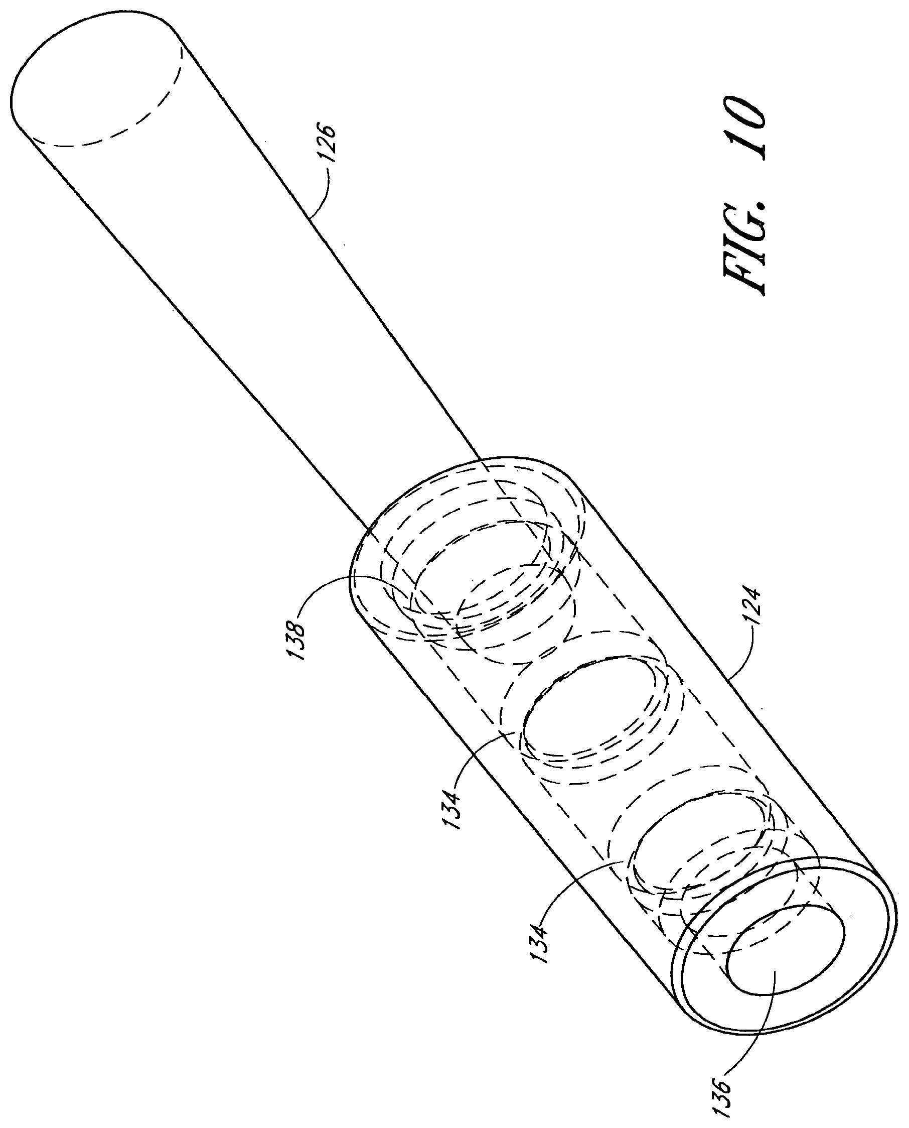
FIG. 10 is a perspective view of one embodiment of a knot.
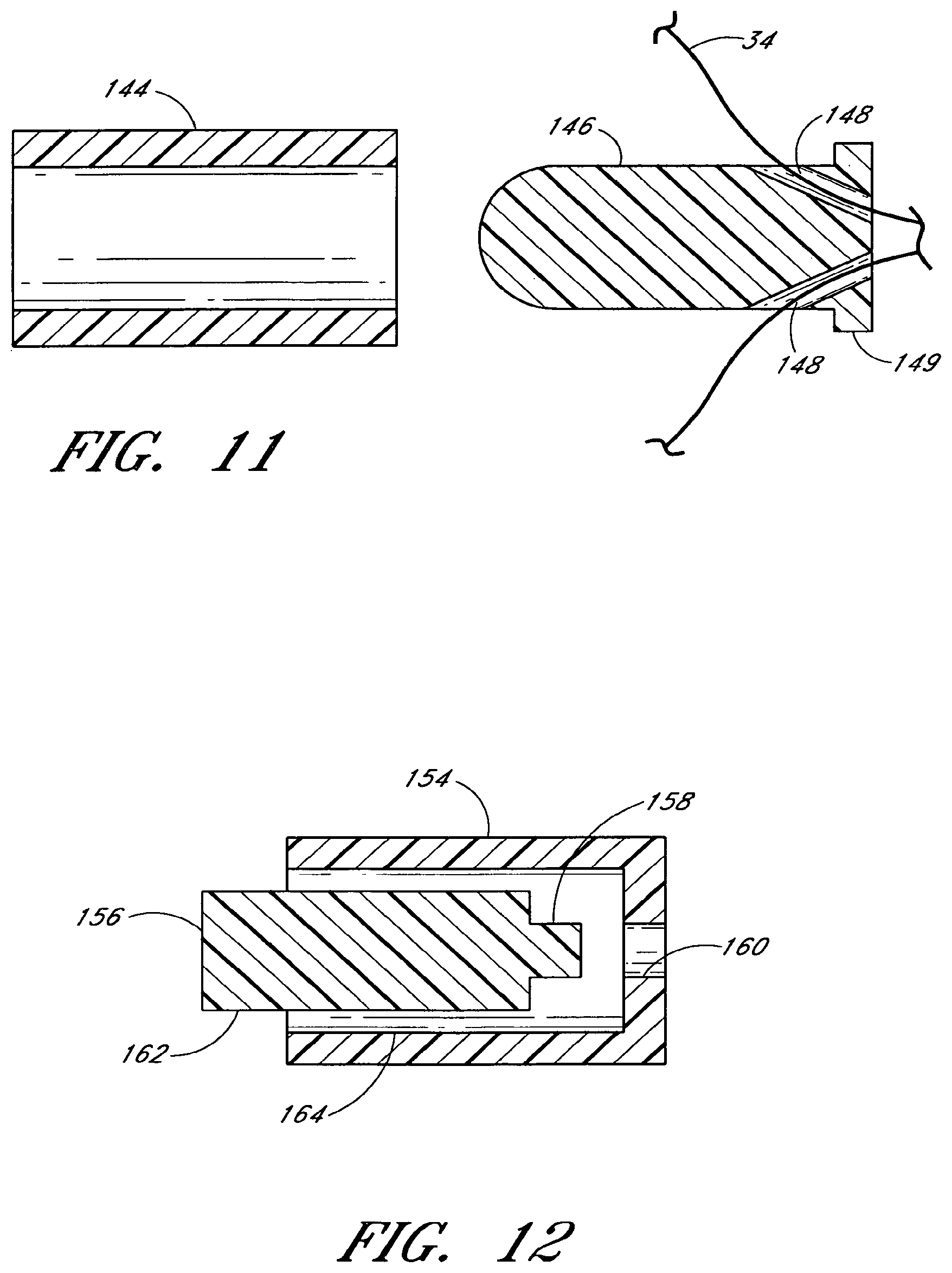
FIG. 11 is a cross-sectional side view of another embodiment of a knot.
FIG. 12 is a cross-sectional side view of another embodiment of a knot.
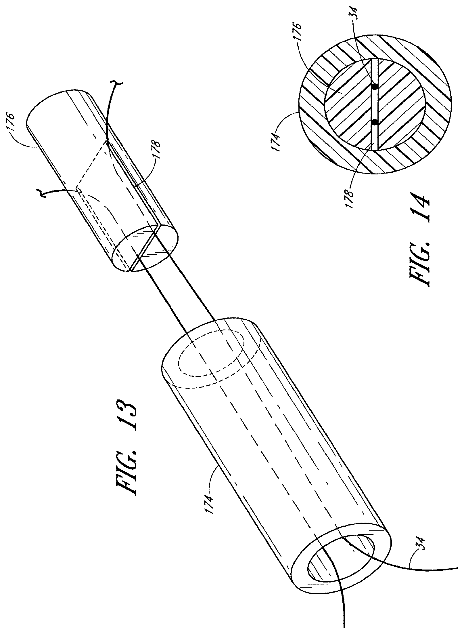
FIG. 13 is a perspective view of another embodiment of a knot.
FIG. 14 is a transverse cross-sectional view of the knot of FIG. 13.
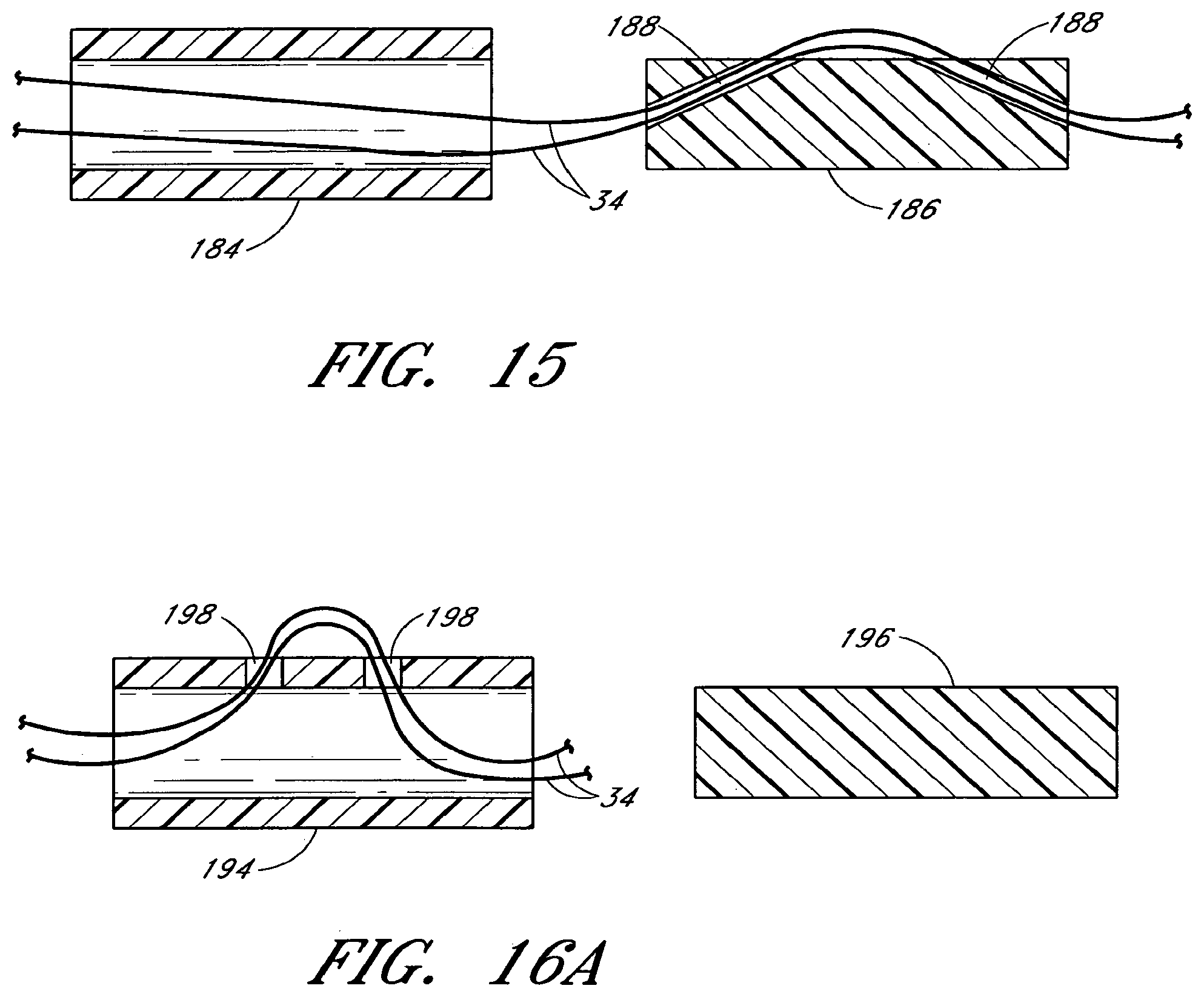
FIG. 15 is a cross-sectional side view of another embodiment of a knot.
FIG. 16a is a cross-sectional side view of another embodiment of a knot and illustrating a routing of a suture through the knot body.
FIG. 16b is a cross-sectional side view of the embodiment of the knot of FIG. 16a and illustrating an alternative routing of a suture through the knot body.
FIG. 17a is a perspective view of another embodiment of a knot.
FIG. 17b is a cross-sectional side view of the embodiment of a knot shown in FIG. 17.
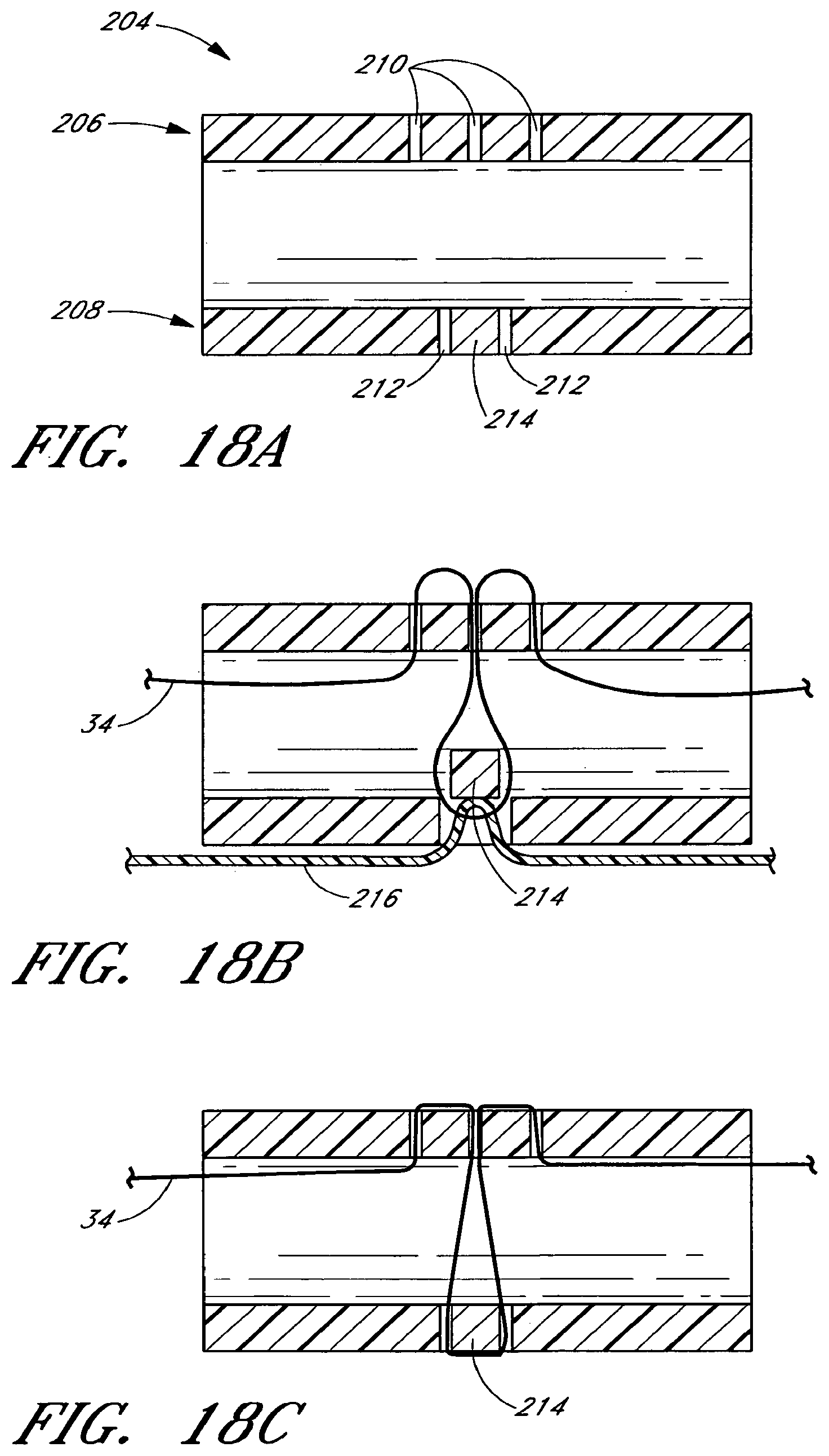
FIG. 18a is a cross-sectional side view of another embodiment of a knot.
FIG. 18b is a cross-sectional side view of the knot of FIG. 18a.
FIG. 18c is a cross-sectional side view of the knot of FIGS. 18a-18b.
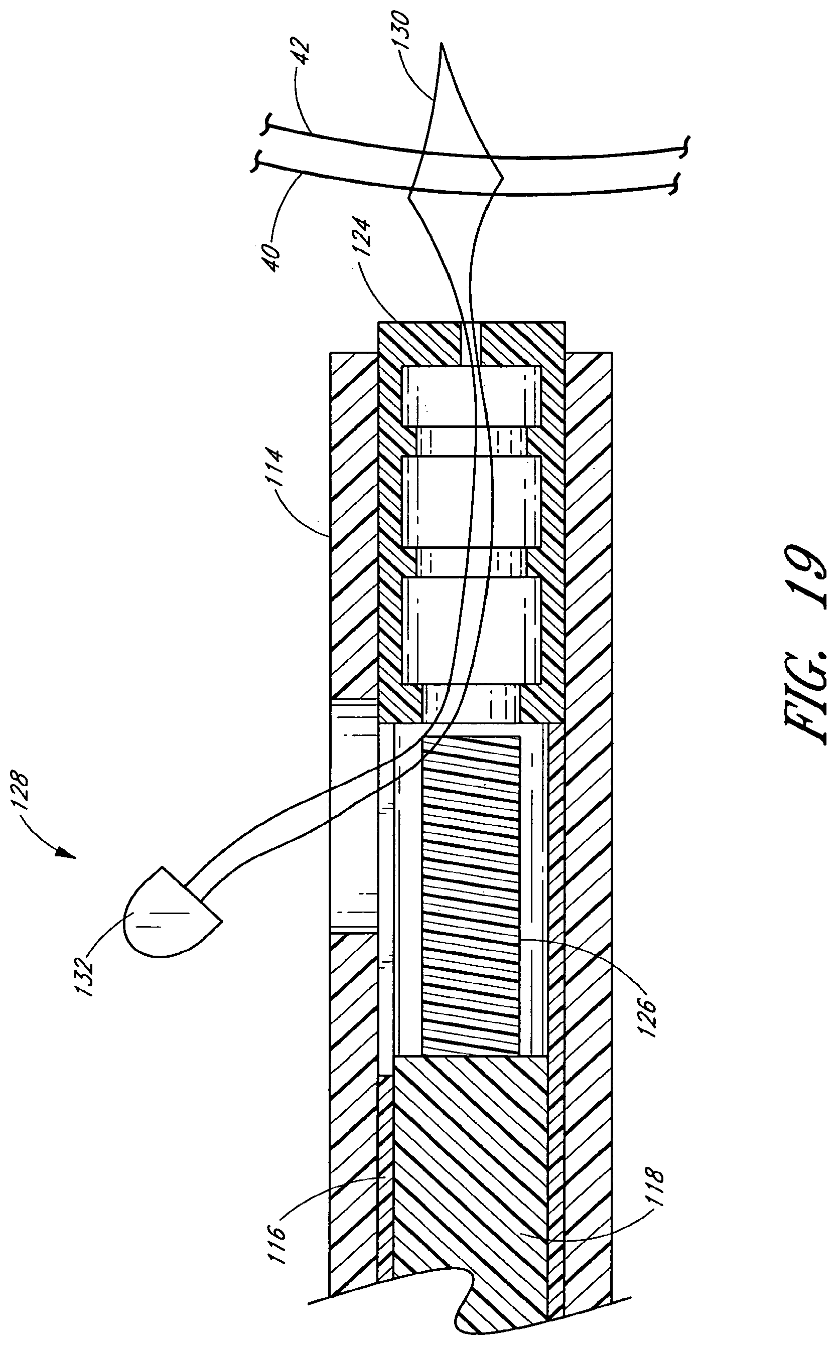
FIG. 19 is a partial cross-sectional view of a knot placement device, with suture ends passing through a threader.
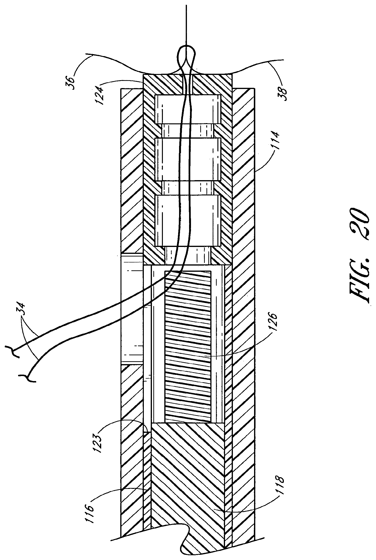
FIG. 20 illustrates the device of FIG. 19 having two suture portions passing therethrough, with the distal end of the device in contact with a tissue portion.
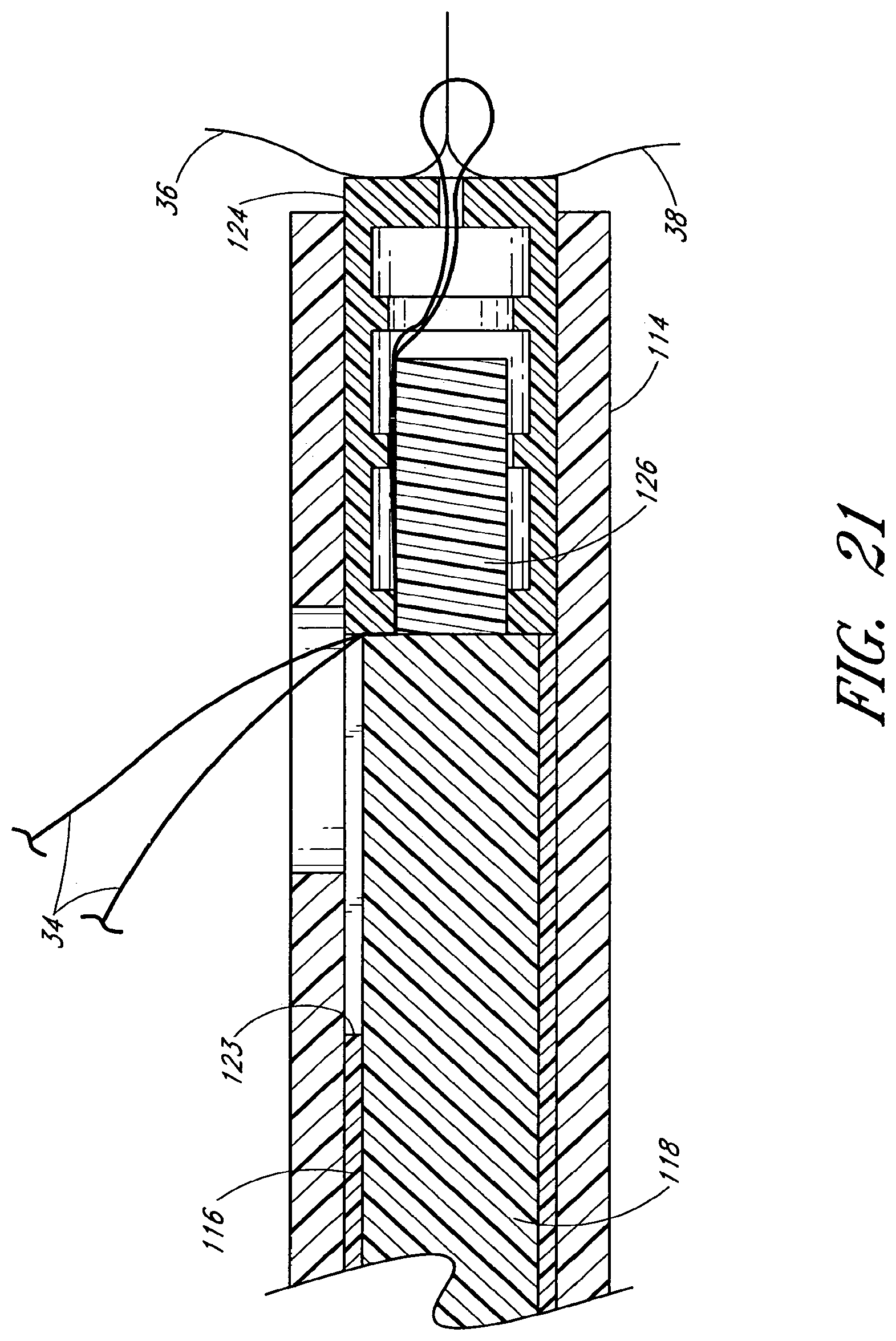
FIG. 21 illustrates the device of FIGS. 19-20 with the push rod being advanced until the plug is inserted into the knot body, trapping the suture portions between the plug and knot body.
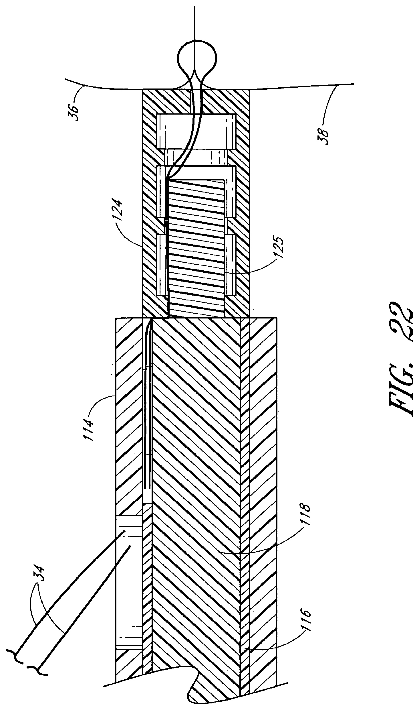
FIG. 22 illustrates the device of FIGS. 19-21, the push rod being further advanced, the intermediate tube also being advanced to eject the knot from the device and sever the suture portions.
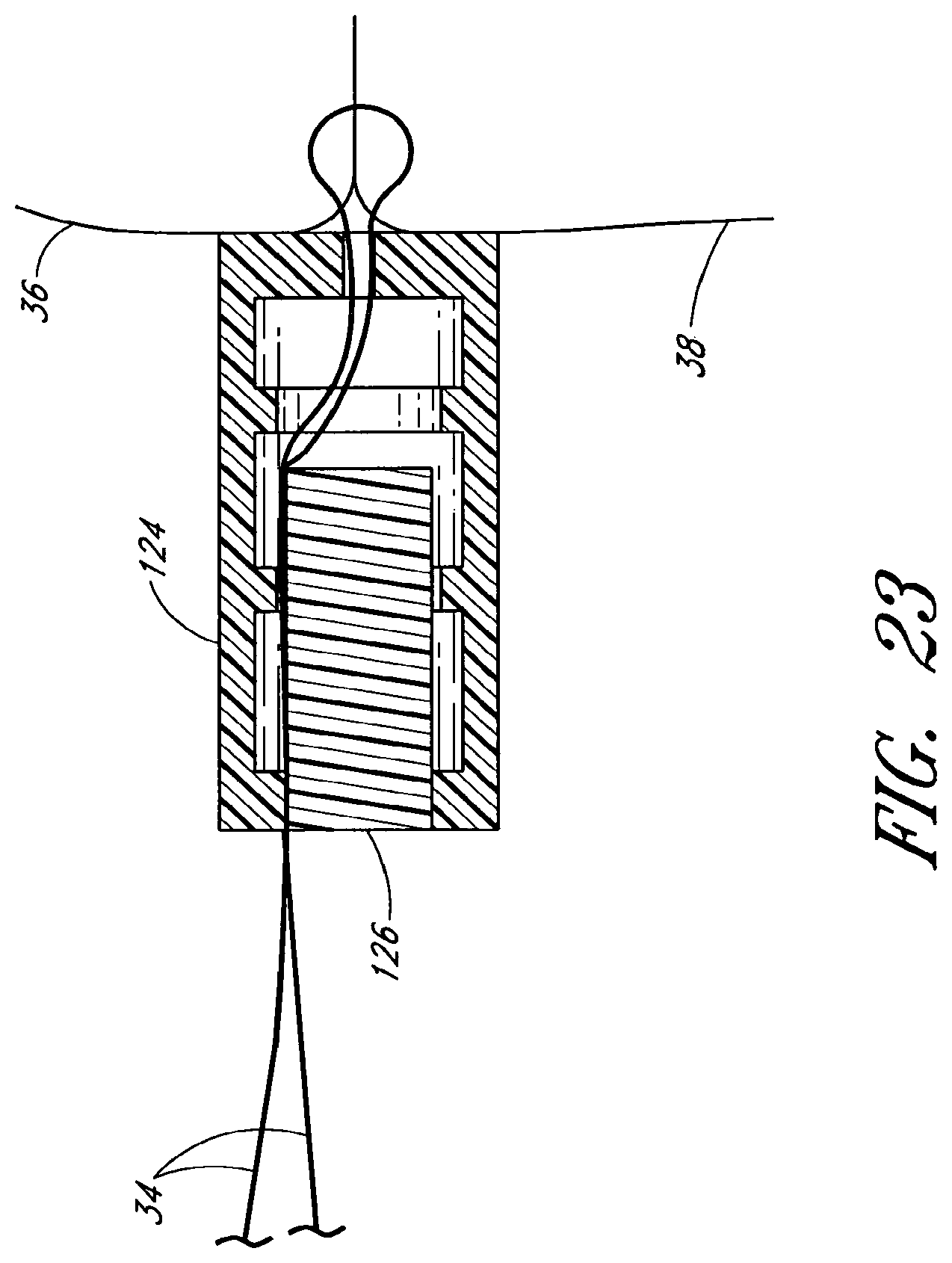
FIG. 23 illustrates the knot of FIGS. 19-22, in its final placement.
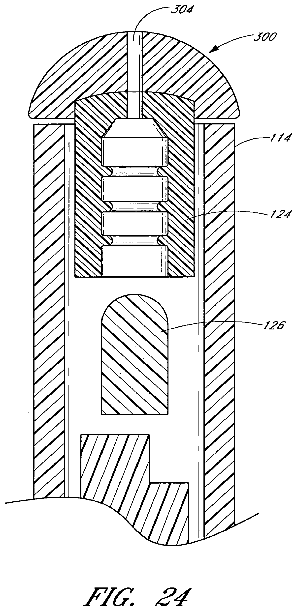
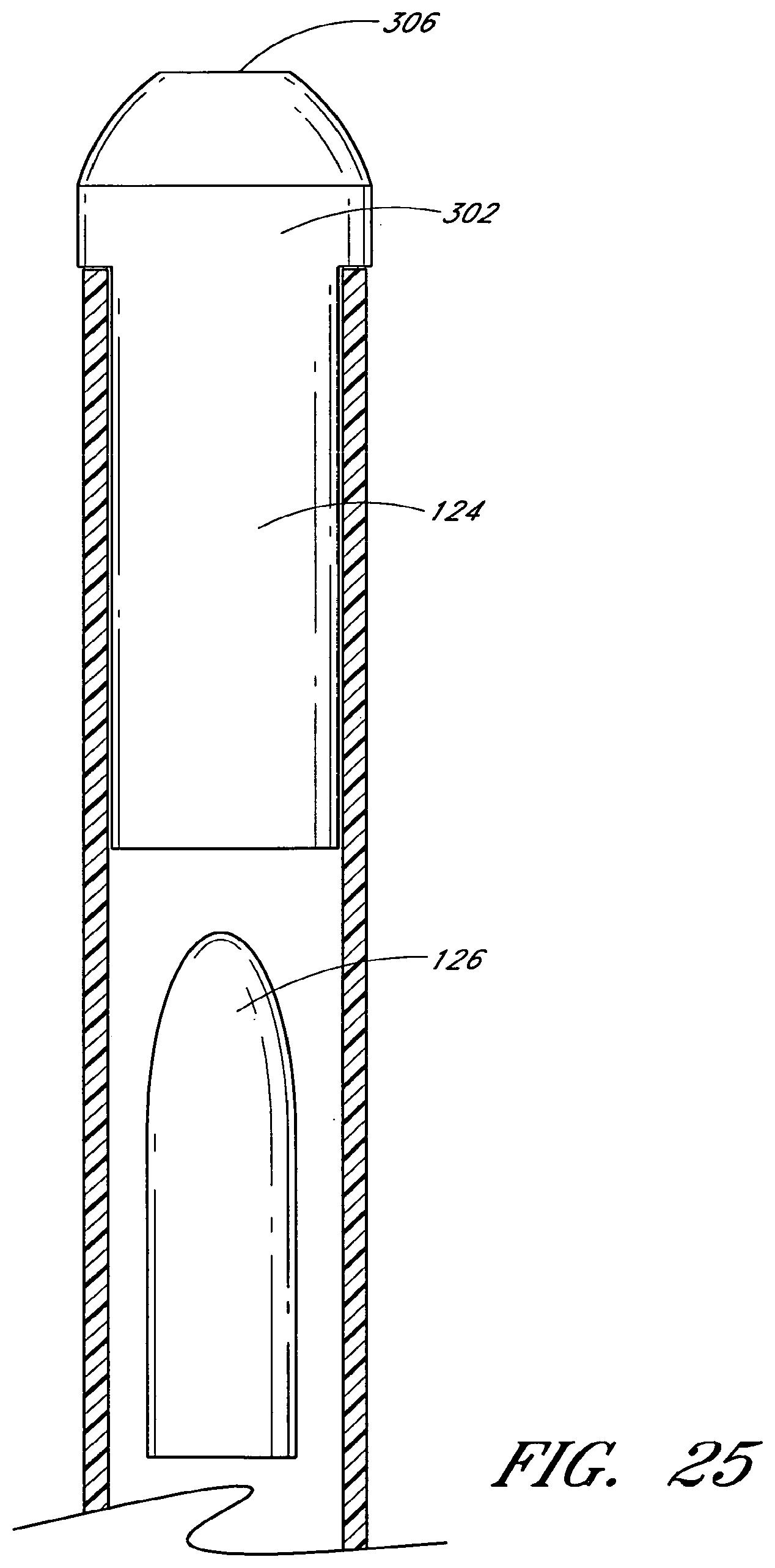
FIGS. 24 and 25 illustrate another embodiment of a knot having an atraumatic tip.
DETAILED DESCRIPTION OF THE PREFERRED EMBODIMENTS
The preferred embodiments of the present invention described below relate particularly to applying a knot to two portions of a suture. More particularly, the preferred embodiments relate to applying a knot to portions of a suture extending from a treatment location of a patient. The treatment location may be any desired location, such as an arterial vessel, a venous vessel, or any other body tissue. Suture ends may be the ends of the same suture or may be the ends of separate sutures.
FIG. 1 illustrates the wound site of a patient wherein it may be desired to apply a knot to a suture. More particularly, FIG. 1 shows an incision 30 in the patient's skin used to perform any sort of treatment on the patient. After the patient has been treated, a suture 34 is introduced into the patient through a catheter sheath introducer (CSI) 44 for the purpose of drawing together tissue portions 36 and 38 (shown in phantom in FIG. 1). Two end portions 40 and 42 of the suture 34 extend from the tissue portions 36, 38, respectively, which may, for example, be the result of a wound or an internal incision in a blood vessel or an organ. The suture 34 may be introduced into the patient by any suitable manner, including those described in U.S. Pat. Nos. 5,860,990, 6,117,144, 6,562,052, and Applicant's co-pending application Ser. No. 11/235,751 filed Sep. 27, 2005, now U.S. Publication No. 2006-0069397, all of which are hereby incorporated by reference in their entirety. Suture 34 may be, but is not limited to, 0.007'' diameter biodegradable material or non-biodegradable materials, such as polypropylene. The suture 34 may also be braided or may be of other materials and have other configurations. The suture 34 in FIG. 1 is shown extending from a catheter sheath introducer 44. The suture 34 may also extend directly from an incision in a patient.
FIGS. 2-4 illustrate one embodiment of a knot placement device 100 that may be used to apply a knot to the suture 34. The knot placement device 100 comprises a handle 102 and a shaft 104 extending distally from the handle. The handle 102 preferably comprises an elongate tubular body extending from a proximal end to a distal end, and comprises an actuator 106 and a distal end portion 110. The handle 102 may further comprise a cam 108 and a spring 112, shown in its rest position, disposed between the cam 108 and end portion 110. The actuator 106 may be a thumb or finger button in contact with the cam 108. End portion 110 may be fixedly attached to an outer tube 114 by glue, press fit, injection molding, or other suitable means know to one of ordinary skill in the art. An intermediate tube 116 may be concentrically and slidably disposed within the outer tube 114. A push rod 118 is concentrically and slidably disposed within the intermediate tube 116 and fixedly attached to the cam 108. It should be appreciated that it is contemplated that the knot placement device 100 does not necessarily comprise an intermediate tube 116; however its inclusion provides certain benefits.
As shown in FIG. 4, depression of the actuator 106 causes the cam 108 to move distally, compressing the spring 112 (not shown), thereby moving the push rod 108. After traveling for a certain desired distance, the cam 108 engages a proximal end of the intermediate tube 116, causing the intermediate tube 116 to also move distally. Upon release of the actuator 106, the spring 112 expands to move the cam 108 and the push rod 118 proximally. In the illustrated embodiment, the intermediate tube 116 is freely slidable over the push rod 118.
In one embodiment, not shown, the cam 108 comprises a detent in the surface which contacts the actuator 106. The detent may signal to the user a specific degree of advancement of the push rod 118, the intermediate tube 116, or both. For example, the detent may signal that the push rod has been advanced sufficiently far to insert the plug into the knot body, as described below. The detent may also indicate travel up until, but not including, the point at which the cam 108 engages the intermediate tube 116. The detent may be shaped so as to prevent the actuator 106 from returning to its original position. The cam may comprise multiple detents to indicate multiple increments of travel. To return the actuator to its initial position, the actuator and cam may include a mechanism such that after the actuator is fully depressed, the actuator may automatically return to its initial position. Alternatively, the actuator may have a locked configuration, either at one of the detents or in a fully depressed configuration, and the handle may include a mechanism by which a second actuator is used to release the cam and actuator to return to their initial positions. Further details of such mechanisms are found in application Ser. No. 11/235,751 filed Sep. 27, 2005, the entirety of which is hereby incorporated by reference.
In one embodiment, not shown, the intermediate tube 116 may comprise a keyway and the outer tube 114, the end portion 110, or both may comprise a key. Alternatively, the intermediate tube 116 may comprise a key and the outer tube 114, the end portion 110, or both may comprise a keyway. Providing such a key and keyway may be used to keep the intermediate tube 116 aligned with the outer tube. Other embodiments are contemplated to maintain rotational alignment of the intermediate tube, such as rotationally fixing the intermediate tube relative to the push rod. Providing such a key and keyway may also be used to constrain the range of sliding movement of the intermediate tube 116.
As shown in FIG. 5, a knot, comprising a knot body 124 and a plug 126, is disposed within the outer tube 114 at its distal end. The knot body 124 may be retained in the outer tube 114 by a net fit or press fit. Alternatively, the fit between the knot body 124 and the outer tube 114 may not retain the knot body 124 in the outer tube 114. The knot body 124 is preferably at the distal end of the outer tube 114, and may protrude slightly distal to the distal end of outer tube 114. The plug 126 is positioned proximal to the knot body 124, and may be slidably disposed within the intermediate tube 116, having a distal end located proximally from the knot body and distally from the push rod 118. The plug 126 has an outer dimension configured to be inserted into an inner cavity of the knot body 124. The intermediate tube 116 is preferably sized and positioned such that its distal end may abut knot body 124.
As shown in FIGS. 5, 6 and 8, the outer tube 114 may include a side hole 120 near its distal end. As shown in FIGS. 5, 7, 9a and 9b, the intermediate tube 116 may include a slot 122 extending proximally from its distal end, forming a C-shaped cross section. At a proximal end of the slot 122, a sharpened cutting surface 123 may be provided to cut suture 34, as described below. The slot 122 is preferably rotationally aligned with the opening 120, such as by using a key/keyway arrangement as described above. The slot 122 is also preferably axially aligned with the opening 120, although it will be appreciated that because of the ability of the intermediate tube 116 to slide relative to push rod 118, the intermediate tube may be positioned with the slot 122 proximal to the opening 120 and its distal end proximal to the plug 126. The slot 122 may also be spaced from the distal end of the intermediate tube, such that the distal end of the tube still forms a complete circle in cross-section. The outer tube 114, intermediate tube 116 and push rod 118 may be made of any suitable material, including but not limited to metals, plastics, and a combination of metals and plastics.
As shown in FIG. 5, in a preloaded configuration, the knot placement device 100 may include a threader 128 comprising a tab 132 and a looped wire 130 passing through the side hole 120 in the outer tube 114. The wire 130 preferably extends through the slot 122 located in the intermediate tube 116, and through knot body 124, exiting through opening 136 at the distal end of the knot body 124. The threader 128 is used to load the suture into the knot placement device as described below. The threader 128 also prevents the knot body 124 from escaping from the placement device 100 when the knot body is provided with an outer dimension of the same or smaller size than the inner wall of the outer tube 114.
With reference to FIGS. 5 and 10, the knot body 124 may be generally tubular and comprise a proximal end, a distal end, and a longitudinal axis. The knot body 124 preferably further defines an inner cavity and comprises an opening 136 at its distal end. The knot body may be of a generally constant inner diameter and outer diameter. Alternatively, the inner diameter, the outer diameter, or both may generally taper along the longitudinal axis of the knot body. Alternatively, the inner diameter, the outer diameter, or both may generally taper along a portion of the longitudinal axis and may be of a generally constant inner diameter, outer diameter or both over a portion of the longitudinal axis.
The opening 136 at the distal end of the knot body may, in some embodiments, be of a reduced diameter relative to an inner cavity of the knot body 124. The knot body also comprises an opening 138 at the proximal end. The opening 138 at the proximal end may, in some embodiments, be of a reduced diameter relative to an inner cavity of the knot body 124. The knot body may further comprise protrusions 134 extending from the inner surface of the knot body 124 toward the longitudinal axis. Protrusions 134 may be formed as rings as illustrated, or as spirals, spikes, bumps, or other suitable structures or combinations of structures.
Referring to FIGS. 5 and 10, in one embodiment, the knot body 124 may be located distally from the plug 126 within the outer tube 114. The plug is preferably sized to be inserted into the inner cavity of the knot body 124, and may have a tapered configuration as shown in FIG. 10. Alternatively, the plug 126 may have a constant cross-section over a majority of its length, such as shown in FIG. 5, with a tapered, chamfered or rounded distal end for facilitating insertion into the knot body 124. The outer dimension of the plug 126 may be slightly larger than the inner dimension of the cavity of the knot body 124, such that when the plug is inserted into the cavity, a relatively secure fit is provided between the two. The protrusions 134 within the knot body further facilitate the relative securement. The plug 126 may also comprise indentations, not shown, for receiving the protrusions 134 to secure the plug 126 more surely in the knot body 124. Other embodiments are contemplated wherein protrusions are formed on the plug 126 with or without indentations formed in the inner cavity of the knot body 124. It is also contemplated that in some embodiments both the plug 126 and the knot body 124 may comprise protrusions and indentations, respectively. In certain embodiments, insertion of the plug 126 into the knot body 124 may cause the knot body 124 to slightly expand. Both the knot and the knot body may be formed of any suitable resilient materials, and in one embodiment, are made from the same material as the suture, more preferably polypropylene.
FIGS. 19-23 illustrate one embodiment for placing a knot utilizing the knot placement device 100 described above. With reference to FIG. 19, a pair of sutures ends 40 and 42 may be passed through the loop 130 of threader 128. The threader is preloaded into the knot placement device 100 as described above. The tab 132 of threader 128 may be pulled proximally to dispose suture 34 in the device, as shown in FIG. 20. Suture 34 may be held in tension, by hand or otherwise, while the device 100 is advanced until the knot body 124 or shaft 104 contacts at least one of tissue portions 36 and 38, as illustrated in FIG. 20. The actuator 106 may be depressed to advance the push rod 118, thereby forcing the plug 126 distally into the knot body 124 and trapping suture 34 there between the plug 126 and the knot body 124, as shown in FIG. 21. The actuator may be further depressed until the cam 108 contacts the proximal end of intermediate tube 116, causing the intermediate tube 116 to contact knot body 124 and eject the knot from the shaft 104. As shown in FIG. 22, advancement of intermediate tube 116 may also cause cutting surface 123 to sever suture 34 where it extends out of opening 120. The knot placement device may then be removed, leaving the knot in place against the tissue portions, as shown in FIG. 23.
In one embodiment, the knot may be ejected from the shaft 104 while leaving the sutures 34 un-severed. For example, the knot may be ejected before the cutting surface 123 reaches the suture 34. In another embodiment, no intermediate tube is provided, and the suture may be cut manually.
In an embodiment including the intermediate tube, the device 100 may be configured such that the distal ends of the outer tube 114, intermediate tube 116, and the push rod 118 lie generally flush relative to one another and are held relatively in position. This position may be held, for example, by depressing the actuator until it rests in a detent in cam 108. The detent may signal to the user that the plug 126 has been inserted into knot body 124, but also that the sutures 34 have not been cut. At such time, the placement device may be used to further advance the knot against tissue portions 36 and 38 using the distal end surface of the shaft. The actuator may be further depressed to advance the push rod 118 and intermediate tube 116 to sever sutures 34.
The actuator 106 and cam 108 may also be provided with locking mechanisms that prevent the actuator 106 from returning to its original position. Further details are provided in application Ser. No. 11/235,751 filed Sep. 27, 2005, the entirety of which is hereby incorporated by reference. Such an embodiment may be advantageous to hold the push rod flush with the distal end of the outer tube to provide a surface that can be utilized to further advance and position the knot against tissue portions 36 and 38.
It will be appreciated that other embodiments are contemplated without use of the intermediate tube, but are still capable of severing the suture. For example, the push rod may be provided with portions of differing diameter. A distal, smaller diameter may be sized to engage the plug 126 to push the plug into the knot body 124. A proximal, larger diameter may be provided on the push rod, which includes a sharpened surface at the transition between the larger and smaller diameter sections. Once the smaller portion of the push rod pushes the plug 126 into the knot body 124, the larger portion of the push rod may engage the knot body 124 to push the knot out of the placement device, while the sharpened surface on the push rod may sever the suture.
In the embodiment described above, when the knot body 124 and the plug 126 as described above are secured together, suture portions extending through the inner cavity of the knot body from opening 136 to opening 138 will be fixedly secured therein, forming a knot. It will be appreciated that many other embodiments are possible for forming a knot, including various other shapes and configurations for the knot body and plug, as well as embodiments wherein only one component may be used to provide securement relative to a suture. It will also be appreciated that in those embodiments in which the knot comprises a knot body and plug, the plug may be located within the shaft proximally from the knot body or the knot body may be located within the shaft proximally from the plug.
For example, in another embodiment of a knot, shown in FIG. 11, a plug 146 is provided having a pair of holes 148 extending divergently from one end of the plug (e.g., a proximal end) to the diametrically opposed, outer surfaces of the plug. A shoulder 149 of increased outer diameter may be located at one end of plug 146 (e.g., the proximal end). When the plug 146 is inserted into a hollow knot body, the plug 146 and knot body 144 cooperate to secure the suture 34 therebetween.
In another embodiment, shown in FIG. 12, a plug 156 may comprise two sections having different outer diameters. A knot body 154 has an opening 136 with an inner surface 160. A surface 162 of plug 156 may have a smaller diameter than an interior surface 164 of knot body 154. A surface 158 of plug 156 may have a diameter such that surface 158 engages surface 160 of knot body 154 and cooperate to hold suture portions securely therein.
In another embodiment, shown in FIGS. 13 and 14, a plug 176 comprises a longitudinally-extending slot 178 such that plug 176 is generally fork-shaped. The slot 178 extends from the distal end partially to the proximal end. Suture 34 extends through the knot body 174, through the slot 178, and out from the plug 176, preferably on opposite sides of the plug 176. Insertion of the plug 176 into knot body 174 preferably causes compression of the slot to securely fix the suture portions within the slot. It will be appreciated that in this embodiment, the knot placement device can either be actuated to move the plug distally into the knot body, or alternatively, may be actuated to move the knot body distally over the plug.
In another embodiment, shown in FIG. 15, a pair of side holes 188 are provided at spaced locations along the length of a plug 186. Suture portions pass from an end hole at one end of the plug 186, outwardly through one of the side holes, and then inwardly back into the body of the plug and out an opposite end hole. When the knot body 184 is slid over the plug, either by being advanced distally over the plug or by having the plug advanced distally into the knot body, the suture 34 is secured relatively between the plug and the knot body.
In another embodiment, shown in FIGS. 16a and 16b, a knot body 194 comprises two side holes 198. Suture 34 may be routed through knot body 194 either from within the body, out through one of the side holes, and back into the body through the other side hole, as shown in FIG. 16a, or may be routed into one of the side holes from outside the body, into the body, and then out the other side hole, as shown in FIG. 16b. In either embodiment, a plug 196 may then be used to secure the suture relative to the knot body.
In another embodiment, shown in FIGS. 17a and 17b, a knot 200 comprises a single component or knot body. A plate, ring or other structure, such as a flat resilient member, may be provided with two holes 202. As shown in FIG. 17b, the plate is bent to form a "U" shape, to allow the suture 34 to be passed therethrough. The plate may be made of an elastic or shape memory material which springs back to its flattened configuration, shown in FIG. 17a, which locks the suture in place relative to the plate. Other embodiments are also contemplated in which suture portions are provided through a tortuous path of a knot body. A threader as described above may be used to guide the suture portions through the knot body while it is positioned within a knot placement device. Once ejected from the knot placement device, the knot body may assume a different configuration which locks the suture in place relative to the knot body.
In another embodiment, shown in FIGS. 18a, 18b, and 18c, a knot 204 comprises a tube having an upper wall 206 and a lower wall 208. The upper wall comprises three linearly-spaced apertures 210. The lower wall comprises two apertures 212 to create a displaceable section 214 in the lower wall 208. The displaceable section 208 is displaced toward the center of the knot 204 by any suitable means, such as a curved rod 216 as illustrated in FIG. 18b. A suture 34 is threaded in and out of the apertures 210 in the upper wall and around the displaceable section 214 of the lower wall. As the knot 204 is ejected from the knot placement device, the displaceable section 214 is allowed to move toward its original position to more surely secure the suture 34 within the knot 204 as illustrated in FIG. 18c.
In another embodiment, shown in FIGS. 24 and 25, a knot comprises a knot body 124 and a plug 126 such as described above, but with the knot body having an atraumatic tip 300. The tip 300 may be rounded and have an outer diameter about the same as that of the outer tube 114. As shown more particularly in FIG. 25, the tip may have a flat transition 302 as well. The tip 300 may be integrally formed with the knot body 124 or may be separately attached. As illustrated, the tip 300 may have an aperture 304 extending axially through the tip, opening to the cavity inside the knot body. When the knot is delivered into a patient as described above, the atraumatic tip prevents damage to the patient.
Various other embodiments are contemplated for the knot. For example, a knot may simply comprise a tube with a sufficiently small inner diameter through which suture portions may be positioned and held. In another embodiment not shown, the plug may comprise a shoulder located near its proximal end having an increased outer diameter. The shoulder may not be inserted into the knot body, but may be used to push the knot out of the placement device once the plug has been inserted into the knot body.
It should be understood that certain variations and modifications of this invention will suggest themselves to one of ordinary skill in the art. The scope of the present invention is not to be limited by the illustrations or the foregoing descriptions thereof.
* * * * *
D00000
D00001
D00002
D00003
D00004
D00005
D00006
D00007
D00008
D00009
D00010
D00011
D00012

D00013
D00014
D00015
D00016
D00017
D00018
D00019
D00020
XML
uspto.report is an independent third-party trademark research tool that is not affiliated, endorsed, or sponsored by the United States Patent and Trademark Office (USPTO) or any other governmental organization. The information provided by uspto.report is based on publicly available data at the time of writing and is intended for informational purposes only.
While we strive to provide accurate and up-to-date information, we do not guarantee the accuracy, completeness, reliability, or suitability of the information displayed on this site. The use of this site is at your own risk. Any reliance you place on such information is therefore strictly at your own risk.
All official trademark data, including owner information, should be verified by visiting the official USPTO website at www.uspto.gov. This site is not intended to replace professional legal advice and should not be used as a substitute for consulting with a legal professional who is knowledgeable about trademark law.