Suturing devices and methods for suturing an anatomic valve
Nobles , et al.
U.S. patent number 10,285,687 [Application Number 15/058,236] was granted by the patent office on 2019-05-14 for suturing devices and methods for suturing an anatomic valve. This patent grant is currently assigned to Nobles Medical Technologies Inc.. The grantee listed for this patent is Nobles Medical Technologies, Inc.. Invention is credited to Benjamin G. Brosch, John R. Crew, Anthony A. Nobles.


View All Diagrams
| United States Patent | 10,285,687 |
| Nobles , et al. | May 14, 2019 |
Suturing devices and methods for suturing an anatomic valve
Abstract
A device for suturing an anatomic valve can comprise an elongate body, a suture catch mechanism and a suture clasp arm. The suture catch mechanism can be operatively coupled to the elongate body for movement between a retracted position and an advanced position. The suture clasp arm can be attached to the elongate body for movement between a retracted position and an extended position. The suture clasp arm can comprise a suture clasp configured to releasably retain a suture portion. In some embodiments, the suture clasp is positioned on the suture clasp arm such that the suture catch mechanism retrieves the suture portion from the suture clasp arm while the arm is at least partially retracted. In some embodiments, the suture clasp arm can be closed about a tissue portion without damaging the tissue portion.
| Inventors: | Nobles; Anthony A. (Fountain Valley, CA), Brosch; Benjamin G. (Mission Viejo, CA), Crew; John R. (San Francisco, CA) | ||||||||||
|---|---|---|---|---|---|---|---|---|---|---|---|
| Applicant: |
|
||||||||||
| Assignee: | Nobles Medical Technologies
Inc. (Fountain Valley, CA) |
||||||||||
| Family ID: | 40765560 | ||||||||||
| Appl. No.: | 15/058,236 | ||||||||||
| Filed: | March 2, 2016 |
Prior Publication Data
| Document Identifier | Publication Date | |
|---|---|---|
| US 20160174968 A1 | Jun 23, 2016 | |
Related U.S. Patent Documents
| Application Number | Filing Date | Patent Number | Issue Date | ||
|---|---|---|---|---|---|
| 14311518 | Jun 23, 2014 | ||||
| 12463046 | May 8, 2009 | 8771296 | |||
| 61052146 | May 9, 2008 | ||||
| Current U.S. Class: | 1/1 |
| Current CPC Class: | A61B 17/0482 (20130101); A61B 17/0469 (20130101); A61B 2017/06042 (20130101); A61B 2017/047 (20130101); A61B 2017/0488 (20130101); A61B 2017/06057 (20130101); A61B 17/04 (20130101); A61B 2017/0472 (20130101) |
| Current International Class: | A61B 17/04 (20060101); A61B 17/06 (20060101) |
References Cited [Referenced By]
U.S. Patent Documents
| 1064307 | June 1913 | Fleming |
| 1989919 | February 1935 | Everitt |
| 2637290 | May 1953 | Sigoda |
| 2738790 | March 1956 | Todt, Sr. et al. |
| 2945460 | July 1960 | Kagiyama |
| 3241554 | March 1966 | Coanda |
| 3664345 | May 1972 | Dabbs et al. |
| 3665926 | May 1972 | Flores |
| 3828790 | August 1974 | Curtiss et al. |
| 3842840 | October 1974 | Schweizer |
| 3877434 | April 1975 | Ferguson et al. |
| 3882855 | May 1975 | Schulte et al. |
| 3888117 | June 1975 | Lewis |
| 3903893 | September 1975 | Scheer |
| 3946740 | March 1976 | Bassett |
| 3946741 | March 1976 | Adair |
| 4052980 | October 1977 | Grams et al. |
| 4107953 | August 1978 | Casillo |
| 4164225 | August 1979 | Johnson et al. |
| 4230119 | October 1980 | Blum |
| 4291698 | September 1981 | Fuchs et al. |
| 4307722 | December 1981 | Evans |
| 4417532 | November 1983 | Yasukata |
| 4447227 | May 1984 | Kotsanis |
| 4457300 | July 1984 | Budde |
| 4484580 | November 1984 | Nomoto et al. |
| 4512338 | April 1985 | Balko et al. |
| 4553543 | November 1985 | Amarasinghe |
| 4617738 | October 1986 | Kopacz |
| 4662068 | May 1987 | Polonsky |
| 4750492 | June 1988 | Jacobs |
| 4827931 | May 1989 | Longmore |
| 4841888 | June 1989 | Mills et al. |
| 4923461 | May 1990 | Caspari et al. |
| 4926860 | May 1990 | Stice et al. |
| 4935027 | June 1990 | Yoon |
| 4957498 | September 1990 | Caspari et al. |
| 4972845 | November 1990 | Iversen et al. |
| 4981149 | January 1991 | Yoon et al. |
| 5021059 | June 1991 | Kensey et al. |
| 5037433 | August 1991 | Wilk et al. |
| 5057114 | October 1991 | Wittich et al. |
| 5059201 | October 1991 | Asnis |
| 5074871 | December 1991 | Groshong |
| 5078743 | January 1992 | Mikalov et al. |
| 5100418 | March 1992 | Yoon et al. |
| 5104394 | April 1992 | Knoepfler |
| 5108419 | April 1992 | Reger et al. |
| 5133724 | July 1992 | Wilson et al. |
| 5160339 | November 1992 | Chen et al. |
| 5167223 | December 1992 | Koros et al. |
| 5171251 | December 1992 | Bregen et al. |
| 5176691 | January 1993 | Pierce |
| 5222508 | June 1993 | Contarini |
| 5222974 | June 1993 | Kensey et al. |
| 5224948 | July 1993 | Abe et al. |
| 5242459 | September 1993 | Buelna |
| 5281234 | January 1994 | Wilk et al. |
| 5281237 | January 1994 | Gimpelson |
| 5282827 | February 1994 | Kensey et al. |
| 5304184 | April 1994 | Hathaway et al. |
| 5312344 | May 1994 | Grinfeld |
| 5320632 | June 1994 | Heidmueller |
| 5336229 | August 1994 | Noda |
| 5336231 | August 1994 | Adair |
| 5337736 | August 1994 | Reddy |
| 5339801 | August 1994 | Poloyko |
| 5356382 | October 1994 | Picha et al. |
| 5364407 | November 1994 | Poll |
| 5364408 | November 1994 | Gordon |
| 5368601 | November 1994 | Sauer et al. |
| 5374275 | December 1994 | Bradley et al. |
| 5383897 | January 1995 | Wholey |
| 5383905 | January 1995 | Golds et al. |
| 5391147 | February 1995 | Imran et al. |
| 5391174 | February 1995 | Weston |
| 5397325 | March 1995 | Badia et al. |
| 5403329 | April 1995 | Hinchcliffe |
| 5405354 | April 1995 | Sarrett |
| 5417699 | May 1995 | Klein et al. |
| 5417700 | May 1995 | Egan |
| 5423837 | June 1995 | Mericle et al. |
| 5425737 | June 1995 | Burbank et al. |
| 5425744 | June 1995 | Fagan et al. |
| 5429118 | July 1995 | Cole et al. |
| 5431666 | July 1995 | Sauer et al. |
| 5439470 | August 1995 | Li |
| 5445167 | August 1995 | Yoon et al. |
| 5454823 | October 1995 | Richardson et al. |
| 5458609 | October 1995 | Gordon et al. |
| 5462560 | October 1995 | Stevens |
| 5462561 | October 1995 | Voda |
| 5470338 | November 1995 | Whitefield et al. |
| 5474572 | December 1995 | Hayburst |
| 5476469 | December 1995 | Hathaway et al. |
| 5476470 | December 1995 | Fitzgibbons, Jr. |
| 5496332 | March 1996 | Sierra et al. |
| 5499991 | March 1996 | Garman et al. |
| 5501691 | March 1996 | Goldrath |
| 5507755 | April 1996 | Gresl et al. |
| 5514159 | May 1996 | Matula et al. |
| 5520702 | May 1996 | Sauer et al. |
| 5527321 | June 1996 | Hinchliffe |
| 5527322 | June 1996 | Klein et al. |
| 5540704 | July 1996 | Gordon |
| 5545170 | August 1996 | Hart |
| 5549633 | August 1996 | Evans et al. |
| 5562686 | October 1996 | Sauer et al. |
| 5562688 | October 1996 | Riza |
| 5571090 | November 1996 | Sherts |
| 5573540 | November 1996 | Yoon |
| 5584835 | December 1996 | Greenfield |
| 5584861 | December 1996 | Swain et al. |
| 5593422 | January 1997 | Muijs Van de Moer et al. |
| 5603718 | February 1997 | Xu |
| 5613974 | March 1997 | Andreas et al. |
| 5613975 | March 1997 | Christy |
| 5626590 | May 1997 | Wilk |
| 5632751 | May 1997 | Piraka |
| 5632752 | May 1997 | Buelna |
| 5643289 | July 1997 | Sauer et al. |
| 5645553 | July 1997 | Kolesa et al. |
| 5662663 | September 1997 | Shallman |
| 5669917 | September 1997 | Sauer et al. |
| 5681351 | October 1997 | Jamiolkowski et al. |
| 5700273 | December 1997 | Buelna et al. |
| 5700277 | December 1997 | Nash et al. |
| 5707379 | January 1998 | Fleenor et al. |
| 5709693 | January 1998 | Taylor |
| 5720757 | February 1998 | Hathaway et al. |
| 5728109 | March 1998 | Schulze et al. |
| 5746753 | May 1998 | Sullivan et al. |
| 5759188 | June 1998 | Yoon |
| 5766183 | June 1998 | Sauer |
| 5769870 | June 1998 | Salahieh et al. |
| 5779719 | July 1998 | Klein et al. |
| 5792152 | August 1998 | Klein et al. |
| 5792153 | August 1998 | Swain et al. |
| 5797960 | August 1998 | Stevens et al. |
| 5810849 | September 1998 | Kontos |
| 5810850 | September 1998 | Hathaway et al. |
| 5817110 | October 1998 | Kronner |
| 5820631 | October 1998 | Nobles |
| 5836955 | November 1998 | Buelna et al. |
| 5843100 | December 1998 | Meade |
| 5846253 | December 1998 | Buelna et al. |
| 5855585 | January 1999 | Kontos |
| 5860990 | January 1999 | Nobles et al. |
| 5860991 | January 1999 | Klein et al. |
| 5860992 | January 1999 | Daniel et al. |
| 5861003 | January 1999 | Latson et al. |
| 5868762 | February 1999 | Cragg et al. |
| 5876411 | March 1999 | Kontos |
| 5899921 | May 1999 | Caspari et al. |
| 5902311 | May 1999 | Andreas et al. |
| 5902321 | May 1999 | Caspari et al. |
| 5908428 | June 1999 | Scirica et al. |
| 5919208 | July 1999 | Valenti |
| 5931844 | August 1999 | Thompson et al. |
| 5935149 | August 1999 | Ek |
| 5944730 | August 1999 | Nobles et al. |
| 5951590 | September 1999 | Goldfarb |
| 5954732 | September 1999 | Hart et al. |
| 5971983 | October 1999 | Lesh |
| 5972005 | October 1999 | Stalker et al. |
| 5980539 | November 1999 | Kontos |
| 5993466 | November 1999 | Yoon |
| 5997555 | December 1999 | Kontos |
| 6015428 | January 2000 | Pagedas |
| 6024747 | February 2000 | Kontos |
| 6033430 | March 2000 | Bonutti |
| 6036699 | March 2000 | Andreas et al. |
| 6059800 | May 2000 | Hart et al. |
| 6066160 | May 2000 | Colvin et al. |
| 6077277 | June 2000 | Mollenauer et al. |
| 6086608 | July 2000 | Ek et al. |
| 6099553 | August 2000 | Hart et al. |
| 6110185 | August 2000 | Barra et al. |
| 6117144 | September 2000 | Nobles et al. |
| 6126677 | October 2000 | Ganaja et al. |
| 6136010 | October 2000 | Modesitt et al. |
| 6143015 | November 2000 | Nobles |
| 6171319 | January 2001 | Nobles et al. |
| 6174324 | January 2001 | Egan et al. |
| 6187026 | February 2001 | Devlin et al. |
| 6190396 | February 2001 | Whitin et al. |
| 6200329 | March 2001 | Fung et al. |
| 6203565 | March 2001 | Bonutti et al. |
| 6217591 | April 2001 | Egan et al. |
| 6245079 | June 2001 | Nobles et al. |
| 6248121 | June 2001 | Nobles |
| 6280460 | August 2001 | Bolduc et al. |
| 6290674 | September 2001 | Roue et al. |
| 6332889 | December 2001 | Sancoff et al. |
| 6348059 | February 2002 | Hathaway et al. |
| 6383208 | May 2002 | Sancoff et al. |
| 6409739 | June 2002 | Nobles et al. |
| 6432115 | August 2002 | Mollenauer et al. |
| 6527785 | March 2003 | Sancoff et al. |
| 6533795 | March 2003 | Tran et al. |
| 6537299 | March 2003 | Hogendijk et al. |
| 6547725 | April 2003 | Paolitto et al. |
| 6551331 | April 2003 | Nobles et al. |
| 6562052 | May 2003 | Nobles et al. |
| 6663643 | December 2003 | Field et al. |
| 6679895 | January 2004 | Sancoff et al. |
| 6682540 | January 2004 | Sancoff et al. |
| 6716243 | April 2004 | Colvin et al. |
| 6733509 | May 2004 | Nobles et al. |
| 6767352 | July 2004 | Field et al. |
| 6786913 | September 2004 | Sancoff |
| 6978176 | January 2005 | Lattouf |
| 6855157 | February 2005 | Foerster et al. |
| 6893448 | May 2005 | O'Quinn et al. |
| 6911034 | June 2005 | Nobles et al. |
| 6936057 | August 2005 | Nobles |
| 7004952 | February 2006 | Nobles et al. |
| 7083630 | August 2006 | DeVries et al. |
| 7083638 | August 2006 | Foerster |
| 7090686 | August 2006 | Nobles et al. |
| 7090690 | August 2006 | Foerster et al. |
| 7118583 | October 2006 | O'Quinn et al. |
| 7160309 | January 2007 | Voss |
| 7172595 | February 2007 | Goble |
| 7220266 | May 2007 | Gambale |
| 7235086 | June 2007 | Sauer et al. |
| 7326221 | February 2008 | Sakamoto et al. |
| 7399304 | July 2008 | Gambale et al. |
| 7435251 | October 2008 | Green |
| 7449024 | November 2008 | Stafford |
| 7491217 | February 2009 | Hendren |
| 7601161 | October 2009 | Nobles et al. |
| 7628797 | December 2009 | Tieu et al. |
| 7635386 | December 2009 | Gammie |
| 7637926 | December 2009 | Foerster et al. |
| 7722629 | May 2010 | Chambers |
| 7803167 | September 2010 | Nobles et al. |
| 7842051 | November 2010 | Dana et al. |
| 7846181 | December 2010 | Schwartz et al. |
| 7879072 | February 2011 | Bonutti et al. |
| 7905892 | March 2011 | Nobles et al. |
| 7918867 | April 2011 | Dana et al. |
| 7993368 | August 2011 | Gambale et al. |
| 8197497 | June 2012 | Nobles et al. |
| 8246636 | August 2012 | Nobles et al. |
| 8282659 | October 2012 | Oren et al. |
| 8303622 | November 2012 | Alkhatib |
| 8348962 | January 2013 | Nobles et al. |
| 8372089 | February 2013 | Nobles et al. |
| 8469975 | June 2013 | Nobles et al. |
| 8496676 | July 2013 | Nobles et al. |
| 8568427 | October 2013 | Nobles et al. |
| 8771296 | July 2014 | Nobles et al. |
| 9326764 | May 2016 | Nobles et al. |
| 2001/0031973 | October 2001 | Nobles et al. |
| 2002/0045908 | April 2002 | Nobles et al. |
| 2002/0049453 | April 2002 | Nobles et al. |
| 2002/0087178 | July 2002 | Nobles et al. |
| 2002/0096183 | July 2002 | Stevens et al. |
| 2002/0111653 | August 2002 | Foerster |
| 2002/0128684 | September 2002 | Foerster |
| 2003/0078601 | April 2003 | Skikhman et al. |
| 2003/0144673 | July 2003 | Onuki et al. |
| 2003/0149448 | August 2003 | Foerster et al. |
| 2003/0167062 | September 2003 | Gambale et al. |
| 2003/0171760 | September 2003 | Gambale |
| 2003/0181926 | September 2003 | Dana et al. |
| 2003/0208209 | November 2003 | Gambale et al. |
| 2004/0044365 | March 2004 | Bachman |
| 2004/0059351 | March 2004 | Eigler |
| 2004/0093031 | May 2004 | Burkhart et al. |
| 2004/0097968 | May 2004 | Sikikhman et al. |
| 2004/0098050 | May 2004 | Foerster et al. |
| 2004/0210238 | October 2004 | Nobles et al. |
| 2004/0260298 | December 2004 | Kaiseer et al. |
| 2005/0033319 | February 2005 | Gambale et al. |
| 2005/0070923 | March 2005 | McIntosh |
| 2005/0149066 | July 2005 | Stafford |
| 2005/0240226 | October 2005 | Foerster et al. |
| 2005/0261708 | November 2005 | Pasricha et al. |
| 2005/0261710 | November 2005 | Sakamoto et al. |
| 2005/0277986 | December 2005 | Foerster et al. |
| 2005/0288688 | December 2005 | Sakamoto et al. |
| 2006/0047314 | March 2006 | Green |
| 2006/0064115 | March 2006 | Allen et al. |
| 2006/0069397 | March 2006 | Nobles et al. |
| 2006/0074484 | April 2006 | Huber |
| 2006/0095052 | May 2006 | Chambers |
| 2006/0195120 | August 2006 | Nobles et al. |
| 2006/0265010 | November 2006 | Paraschac et al. |
| 2006/0271074 | November 2006 | Ewers et al. |
| 2006/0282088 | December 2006 | Ryan |
| 2006/0282102 | December 2006 | Nobles et al. |
| 2006/0287657 | December 2006 | Bachman |
| 2007/0005081 | January 2007 | Findlay, III et al. |
| 2007/0010829 | January 2007 | Nobles et al. |
| 2007/0032798 | February 2007 | Pantages et al. |
| 2007/0043385 | February 2007 | Nobles et al. |
| 2007/0118151 | May 2007 | Davidson |
| 2007/0213757 | September 2007 | Boraiah |
| 2007/0219630 | September 2007 | Chu |
| 2007/0276413 | November 2007 | Nobles |
| 2007/0276414 | November 2007 | Nobles |
| 2008/0033459 | February 2008 | Shafi et al. |
| 2008/0188873 | August 2008 | Speziali |
| 2008/0228201 | September 2008 | Zarbatany |
| 2008/0234729 | September 2008 | Page et al. |
| 2008/0269786 | October 2008 | Nobles et al. |
| 2009/0036906 | February 2009 | Stafford |
| 2009/0048615 | February 2009 | McIntosh |
| 2009/0105729 | April 2009 | Zentgraf |
| 2009/0105751 | April 2009 | Zentgraf |
| 2009/0118726 | May 2009 | Auth et al. |
| 2009/0287183 | November 2009 | Bishop et al. |
| 2010/0016870 | January 2010 | Campbell |
| 2010/0030242 | February 2010 | Nobles et al. |
| 2010/0042147 | February 2010 | Janovsky et al. |
| 2010/0087838 | April 2010 | Nobles et al. |
| 2011/0190793 | August 2011 | Nobles et al. |
| 2011/0251627 | October 2011 | Hamilton et al. |
| 2012/0165838 | June 2012 | Kobylewski et al. |
| 2013/0238001 | September 2013 | Nobles et al. |
| 2013/0261645 | October 2013 | Nobles et al. |
| 2014/0148825 | May 2014 | Nobles et al. |
| 2014/0163585 | June 2014 | Nobles et al. |
| 2014/0303654 | October 2014 | Nobles et al. |
| 2003212025 | Aug 2003 | AU | |||
| 2006251579 | Nov 2006 | AU | |||
| 2006262498 | Jan 2007 | AU | |||
| 2323084 | Dec 2006 | CA | |||
| 195341 | Feb 2005 | CN | |||
| 1654016 | Aug 2005 | CN | |||
| 101027001 | Aug 2007 | CN | |||
| 101242785 | Aug 2008 | CN | |||
| 101495049 | Dec 2010 | CN | |||
| 101257852 | Aug 2011 | CN | |||
| 102892359 | Jan 2013 | CN | |||
| 103889345 | Jun 2014 | CN | |||
| 0 544 485 | Jun 1993 | EP | |||
| 0 983 026 | Mar 2002 | EP | |||
| 1 196 093 | Apr 2002 | EP | |||
| 0 941 698 | May 2005 | EP | |||
| 0 983 027 | Dec 2005 | EP | |||
| 1 804 677 | Jul 2007 | EP | |||
| 1 570 790 | Nov 2008 | EP | |||
| 2 011 441 | Jan 2009 | EP | |||
| 1036395 | May 2005 | HK | |||
| A 9507398 | Jul 1997 | JP | |||
| H10-43192 | Feb 1998 | JP | |||
| 2001-524864 | Dec 2001 | JP | |||
| 2002-500531 | Jan 2002 | JP | |||
| 2007-503870 | Mar 2007 | JP | |||
| 2008-514305 | May 2008 | JP | |||
| 2008-541857 | Nov 2008 | JP | |||
| 2008-546454 | Dec 2008 | JP | |||
| 4399035 | Oct 2009 | JP | |||
| 2009-261960 | Nov 2009 | JP | |||
| 2010-522625 | Jul 2010 | JP | |||
| 1560129 | Apr 1990 | SU | |||
| WO 92/05828 | Apr 1992 | WO | |||
| WO 93/01750 | Feb 1993 | WO | |||
| WO 95/12429 | May 1995 | WO | |||
| WO 95/17127 | Jun 1995 | WO | |||
| WO 95/25468 | Sep 1995 | WO | |||
| WO 95/25470 | Sep 1995 | WO | |||
| WO 97/03613 | Feb 1997 | WO | |||
| WO 97/47261 | Feb 1997 | WO | |||
| WO 97/07745 | Mar 1997 | WO | |||
| WO 97/12540 | Apr 1997 | WO | |||
| WO 97/20505 | Jun 1997 | WO | |||
| WO 97/27807 | Aug 1997 | WO | |||
| WO 97/40738 | Nov 1997 | WO | |||
| WO 98/12970 | Apr 1998 | WO | |||
| WO 98/52476 | Nov 1998 | WO | |||
| WO 99/45848 | Sep 1999 | WO | |||
| WO 00/002489 | Jan 2000 | WO | |||
| WO 01/001868 | Jan 2001 | WO | |||
| WO 02/024078 | Mar 2002 | WO | |||
| WO 04/012789 | Feb 2004 | WO | |||
| WO 04/096013 | Nov 2004 | WO | |||
| WO 06/127636 | Nov 2006 | WO | |||
| WO 07/001936 | Jan 2007 | WO | |||
| WO 08/121738 | Oct 2008 | WO | |||
| WO 09/081396 | Jul 2009 | WO | |||
| WO 09/137766 | Nov 2009 | WO | |||
| WO 11/094619 | Aug 2011 | WO | |||
| WO 12/142338 | Oct 2012 | WO | |||
| WO 13/170081 | Nov 2013 | WO | |||
| WO 15/002815 | Jan 2015 | WO | |||
Other References
|
US. Appl. No. 13/736,032, filed Jan. 7, 2013, Nobles et al. cited by applicant . U.S. Appl. No. 14/400,309, filed Nov. 10, 2014, Nobles et al. cited by applicant . Advances in Vascular Surgery, by John S. Najarian, M.D. and John P. Delaney, M.D., copyright 1983 by Year Book Publishers, Inc. at pp. 94,95,96, and 224. cited by applicant . Clinical Evaluation of Arteriovenous Fistulas as an Adjunct to Lower Extremity Arterial Reconstructions, by Herbert Dardick, M.D., in Current Critical Problems in Vascular Surgery, copyright 1989 by Quality Medical Publishing Inc., at p. 383. cited by applicant . Current Therapy in Vascular Surgery, 2nd edition, by Calvin B. Ernst, M.D. and James C. Stanley, M.D., copyright 1991 by B.C. Decker, Inc., at pp. A and 140. cited by applicant . Eskuri, A., The Design of a Minimally Invasive Vascular Suturing Device, Thesis submitted to Rose-Hulman Institute of Technology, Nov. 1999. cited by applicant . Manual of Vascular Surgery, vol. 2, Edwin J. Wylie, Ronald J. Stoney, William K. Ehrenfeld and David J. Effeney (Richard H. Egdahl ed.), copyright 1986 by Springer-Verlag New York Inc., at p. 41. cited by applicant . Nursing the Open-Heart Surgery Patient, By Mary Jo Aspinall, R.N., M.N., copyright 1973 by McGraw Hill, Inc., at pp. 216 and 231. cited by applicant . Operative Arterial Surgery, by P.R. Bell, M.D., and W Barrie, M.D., copyright 1981 by Bell, Barrie, and Leicester Royal Infirmary, printed byJohn Wright &Sons, pp. 16, 17, 104, 105, 112, and 113. cited by applicant . Sinus Venous Type of Atrial Septal Defect with Partial Anomalous Pulmonary Venous Return, by Francis Robicsek, MD., et ai, in Journal of Thoracic and Cardiovascular Surgery, Oct. 1979, vol. 78, No. 4, at pp. 559-562. cited by applicant . Techniques in Vascular Surgery, by Denton A. Cooley, MD. and Don C. Wukasch, MD., copyright 1979 by WB. Saunders Co., at pp. 38,57,86,134,156, and 184. cited by applicant . Vascular Access, Principles and Practice, 3rd edition, by Samuel Eric Wilson, MD., copyright 1996, 1988,1980 by Mosby-Year Book, Inc., pp. 89 and 159. cited by applicant . Vascular and Endovascular Surgery, by Jonathan D. Beard and Peter Gainers, copyright 1998 by W. B. Saunders Co., Ltd, p. 414. cited by applicant . Vascular Surgery, 3rd edition, vol. 1, by Robert B. Rutherford, MD., copyright 1989, 1984, 1976 by W. B.SaundersCo., at pp. 347, 348, 354, 594, 607, 622, 675, 677, 680, 698, 700, 721, 727, 735, and 829. cited by applicant . Vascular Surgery, 4th edition by Robert B. Rutherford, MD., copyright 1995,1989,1976, by W.B. Saunders Co., vol. 1, at pp. 400-404, 661, and A. cited by applicant . Vascular Surgery, 4th edition, by Robert B. Rutherford, M.D., copyright 1995, 1989, 1984, 1976 by W. B. Saunders Co., vol. 2, at pp. 1318, 1363, 1426, 1564, and 1580. cited by applicant . Vascular Surgery, by Robert B. Rutherford, M.D. copyright1977 by WB. Saunders Co., at pp. 334 and 817. cited by applicant . European Examination Report, re EP Application No. 09 743 742.9, dated Apr. 18, 2102. cited by applicant . Japanese Office Action dated Jul. 30, 2013 for Japanese Patent Application No. 2011-508705. cited by applicant . Japanese Office Action (Decision of Rejection) dated Feb. 28, 2014 for Japanese Patent Application No. 2011-508705. cited by applicant. |
Primary Examiner: Lynch; Robert A
Claims
What is claimed is:
1. A method for suturing an anatomic valve, the method comprising: delivering an elongate body having a proximal end and a distal end at least partially through an anatomic valve; moving a first arm attached to the elongate body near the distal end of the elongate body from a retracted position to an extended position, the first arm comprising a first suture mount configured to releasably retain a first suture portion; advancing a first suture catch mechanism operatively coupled to the elongate body from a retracted position to an advanced position, wherein the advancing delivers the first suture catch mechanism through a first portion of tissue of the anatomic valve to interact with the first suture portion in the first suture mount; retracting the first suture catch mechanism from the advanced position to the retracted position to retrieve the first suture portion through the first portion of tissue; moving a second arm attached to the elongate body near the distal end of the elongate body from a retracted position to an extended position, the second arm comprising a second suture mount configured to releasably retain a second suture portion; advancing a second suture catch mechanism operatively coupled to the elongate body from a retracted position to an advanced position sequentially after the advancing of the first suture catch mechanism, wherein the advancing delivers the second suture catch mechanism through a second portion of tissue of the anatomic valve to interact with the second suture portion in the second suture mount; retracting the second suture catch mechanism from the advanced position to the retracted position to retrieve the second suture portion through the second portion of tissue; and removing the distal end of the elongate body from the anatomic valve.
2. The method of claim 1, wherein the distal end of the elongate body is delivered into the heart through a hole at the apex of the heart.
3. The method of claim 1, wherein the distal end of the elongate body is delivered through one or more of a mitral valve, an aortic valve, a tricuspid valve, a pulmonary valve, or a bicuspid valve.
4. The method of claim 1, wherein the first arm and the second arm in their extended positions form an acute angle with the distal end of the elongate body.
5. The method of claim 1, wherein the first arm and the second arm in their extended positions form an acute angle with the proximal end of the elongate body.
6. The method of claim 1, wherein the first suture catch mechanism and second suture catch mechanism move generally distally when advancing from their respective retracted position to their respective extended position.
7. The method of claim 1, wherein the first suture portion and the second suture are a part of a single suture.
8. The method of claim 1, further comprising securing the first suture portion to the second suture portion with a knot.
9. The method of claim 1, wherein a distal end of the first and/or second arm is connected at the distal end of the elongate body.
10. The method of claim 1, wherein moving the second arm attached to the elongate body near the distal end of the elongate body from the retracted position to the extended position is performed after retracting the first suture catch mechanism from the advanced position to the retracted position to retrieve the first suture portion through the first portion of tissue.
Description
CROSS-REFERENCE TO RELATED APPLICATIONS
Any and all applications for which a foreign or domestic priority claim is identified in the Application Data Sheet as filed with the present application, are hereby incorporated by reference in their entirety under 37 CFR 1.57.
TECHNICAL FIELD
Embodiments of the present inventions relate to suturing devices and methods. Some embodiments of the present invention relate to suturing devices and methods for suturing an anatomic valve, for example, a heart valve such as a mitral valve, an aortic valve, a tricuspid valve, or a pulmonary valve.
BACKGROUND
Health practitioners frequently use sutures to close various openings such as cuts, punctures, and incisions in various places in the human body. Generally, sutures are convenient to use and function properly to hold openings in biological tissue closed thereby aiding in blood clotting, healing, and prevention of scaring.
SUMMARY OF THE DISCLOSURE
There are some circumstances under which it is not feasible to use conventional sutures and suturing methods to close an opening. Additionally, there are some circumstance under which the use of conventional sutures and suturing methods require invasive procedures that subject a patient to risk of infection, delays in recovery, increases in pain, and other complications.
Some heart valves may be weakened or stretched, or may have other structural defects, such as congenital defects, that cause them to close improperly, which can lead to blood flow contrary to the normal flow direction. This condition, referred to as regurgitation, incompetence, or insufficiency, can reduce blood flow in the normal direction. Regurgitation causes the heart to work harder to compensate for backflow of blood through these valves, which can lead to enlargement of the heart that reduces cardiac performance. While the tricuspid valve and the pulmonary valve may present these conditions, the mitral valve and aortic valve more frequently demonstrate these conditions.
A number of procedures have been developed to repair valves that do not close properly. Among these procedures is the Alfieri technique, sometimes called edge-to-edge repair, which involves suturing edges of the leaflets and pulling the leaflets closer together. In another technique, the chordae tendineae are replaced or shortened. A patch is sometimes applied to leaflets that have openings therein. In some instances, leaflets are reshaped by removing a section of the leaflet that is to be treated and the surrounding portion of the leaflet is sutured closed. Some valves are treated by attaching a ring around the outside of the malfunctioning valve. Other valves may be replaced with biological or mechanical replacements. These procedures are frequently performed by highly invasive procedures, which sometimes require opening a patient's chest, stopping the patient's heart and routing blood through a heart-lung machine. Robotically-assisted procedures have been employed to reduce the size of the openings required for such procedures.
Embodiments of suturing devices and methods for suturing biological tissue are disclosed herein. The suturing devices and their methods of use can be useful in a variety of procedures, such as treating (e.g., closing) wounds and naturally or surgically created apertures or passageways. For example, the suturing devices can be used to treat an anatomical valve, such as a heart valve, including heart valves that may be weakened or stretched, or have other structural defects, such as congenital defects, that cause them to close improperly. In some embodiments, one or more suturing devices can be used to treat or repair valves, such as the tricuspid, pulmonary, mitral, and aortic valves, for example. In some embodiments, one or more suturing devices can be used to perform procedures such as the Alfieri technique (edge-to-edge repair), replacement of the chordae tendineae, shortening of the chordae tendineae, patch application, leaflet reshaping, and attachment of prosthetics, such as rings and biological or mechanical replacement valves, for example.
In some embodiments, the suturing devices can be used to close or reduce a variety of other tissue openings, lumens, hollow organs or natural or surgically created passageways in the body. In some embodiments, the suturing devices can be used to suture prosthetics, synthetic materials, or implantable devices in the body. For example, the devices can be used to suture pledget within the body.
In some embodiments, a device for suturing an anatomic valve comprises an elongate body, a needle, an arm, and a recess positioned between the elongate body and the arm. The needle can be operatively coupled to the elongate body for movement between a retracted position and an advanced position. The arm can be attached to the elongate body near a distal end of the elongate body for movement between a retracted position and an extended position. The arm can comprise a suture mount that is configured to releasably retain a suture portion. The suture mount can be positioned on the arm such that the needle retrieves the suture portion retained in the suture mount when the needle is moved from the retracted position to the advanced position and returned to the retracted position. The recess can be sized and shaped to receive a leaflet of a valve between the elongate body and the arm without damaging the leaflet.
In some embodiments, an anatomic valve can be sutured A suturing device comprising an elongate body can be positioned at least partially within the anatomic valve. A first arm can be deployed from the elongate body with the first arm releasably holding a first suture portion. The first arm can be at least partially closed about a first leaflet of the anatomic valve. While the first arm is at least partially closed about the first leaflet, a first needle can be advanced through the first leaflet to engage the first suture portion. The first suture portion can be drawn through the first leaflet. A second suture portion can be passed through a second leaflet. The first and second suture portions can be secured together.
In some embodiments, a heart valve can be sutured. A first elongate member can be advanced to a heart valve. A first arm can be extended from the elongate member around a first heart valve portion with the first arm releasably holding a first suture portion. A first needle can be advanced from the elongate member through a first heart valve portion to retrieve a first suture portion from the first arm. A second arm can be extended around a second heart valve portion with the second arm releasably holding a second suture portion. A second needle can be advanced through a second heart valve portion to retrieve the second suture portion from the second arm. The first and second suture portions can be secured to each other.
In some embodiments, the anatomic valve can be sutured using a single device, while in other embodiments the anatomic valve can be sutured using multiple devices. In embodiments using multiple devices, any two devices can be introduced to the treatments site using the same access or different accesses.
The disclosure describes examples of some embodiments of the inventions. The designs, figures, and description are non-limiting examples of some embodiments of the inventions. Other embodiments of the devices and methods may or may not include the features disclosed herein. Moreover, disclosed advantages and benefits may apply to only some embodiments of the inventions, and should not be used to limit the inventions.
BRIEF DESCRIPTION OF THE DRAWINGS
The above-mentioned and other features disclosed herein are described below with reference to the drawings of specific embodiments. The illustrated embodiments are intended for illustration, but not limitation. The drawings contain the following figures:
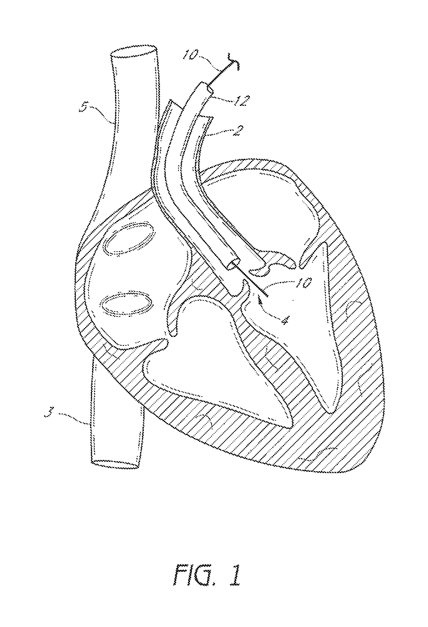
FIG. 1 illustrates a method of providing access to an exemplifying use environment, such as an aortic valve of a heart.
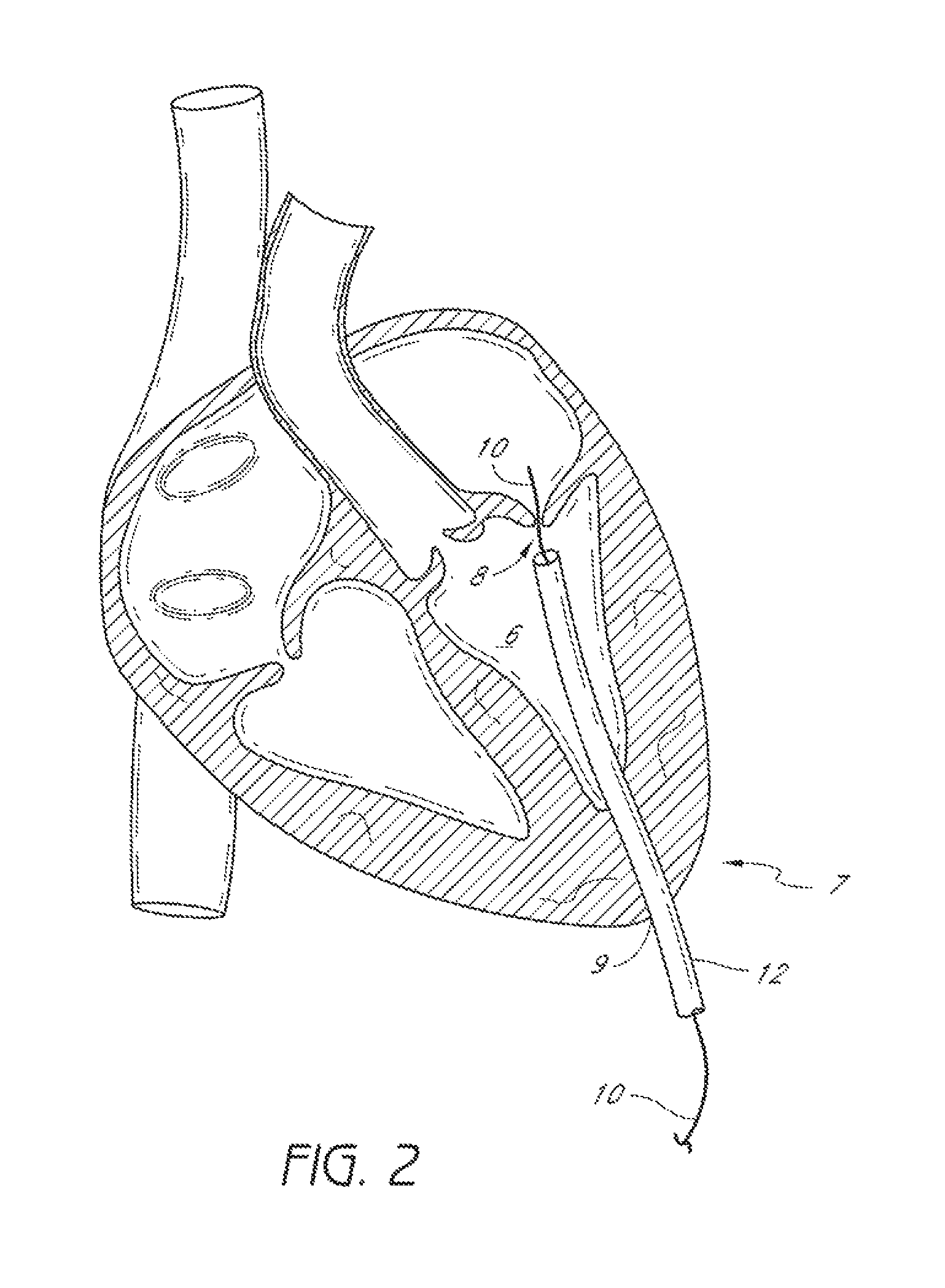
FIG. 2 illustrates a method of providing access to an exemplifying use environment, such as a mitral valve of a heart.
FIG. 3 is a perspective view of an embodiment of a suturing device with suture clasp arms in a retracted position and a casing shown in cross-section.
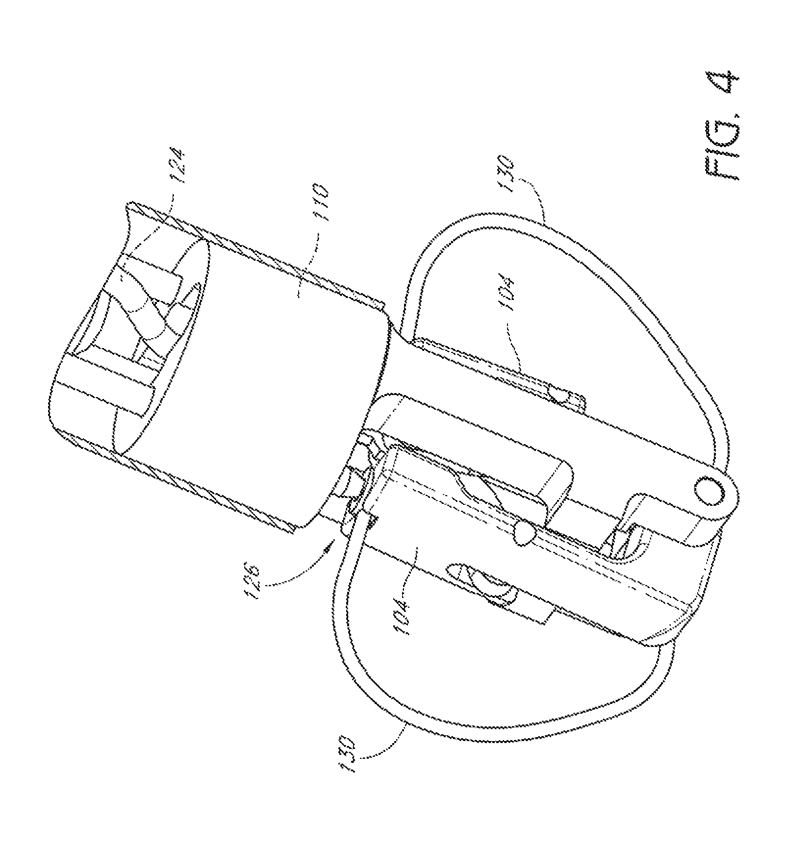
FIG. 4 is an enlarged perspective view of the embodiment of FIG. 3 with the casing shown in cross-section, showing suture catch mechanisms in a partially advanced position.
FIG. 5 is a perspective view of the embodiment of FIG. 3, with the suture clasp arms in an extended position and the suture catch mechanisms in a partially advanced position.
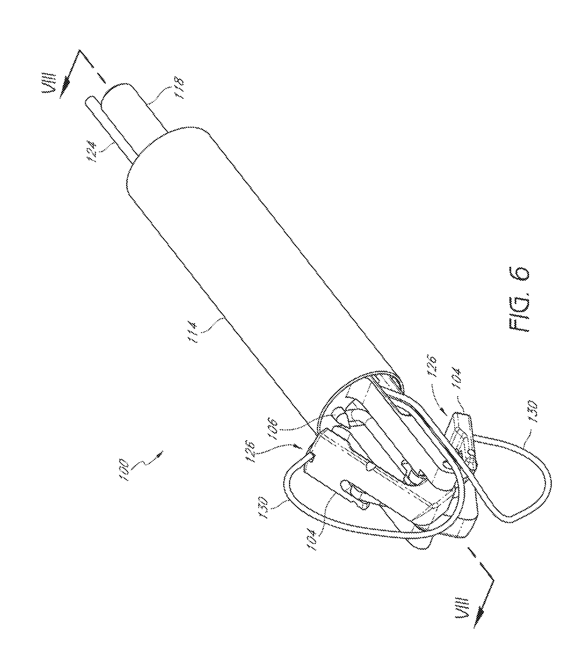
FIG. 6 is a perspective view of the embodiment of FIG. 3, as in FIG. 5, showing a casing attached to the device.
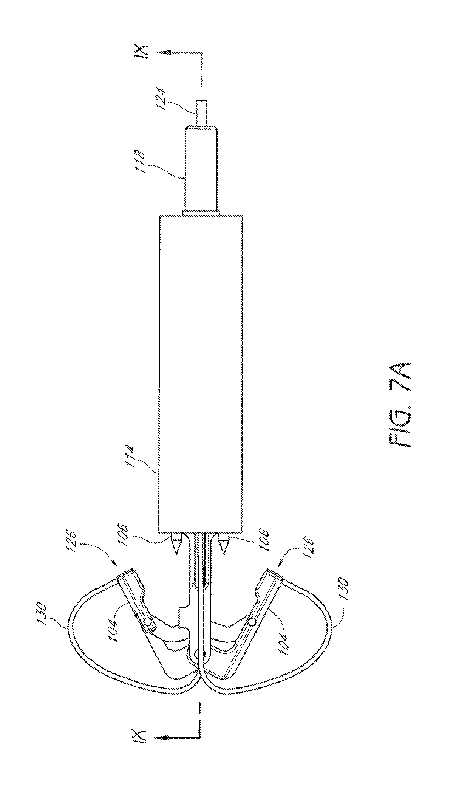
FIG. 7A is a plan view of the embodiment of FIG. 3, with the suture clasp arms in an extended position.
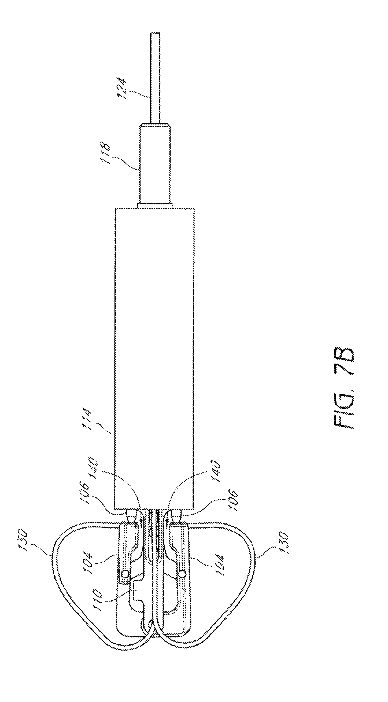
FIG. 7B is a plan view as in FIG. 7A, but with the suture clasp arms retracted.
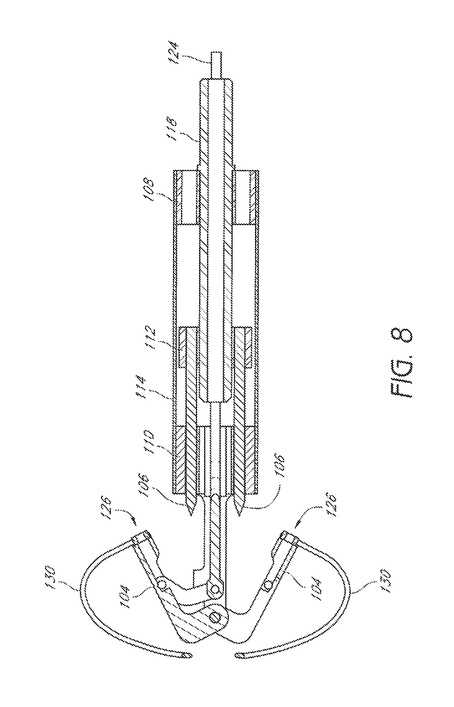
FIG. 8 is a cross-sectional view of the embodiment of FIG. 3, along a line VIII-VIII in FIG. 6.
FIG. 9 is a cross-sectional view of the embodiment of FIG. 3, along a line IX-IX in FIG. 7A.
FIG. 10 is a schematic representation an embodiment of a suturing device positioned in a passage through a valve.
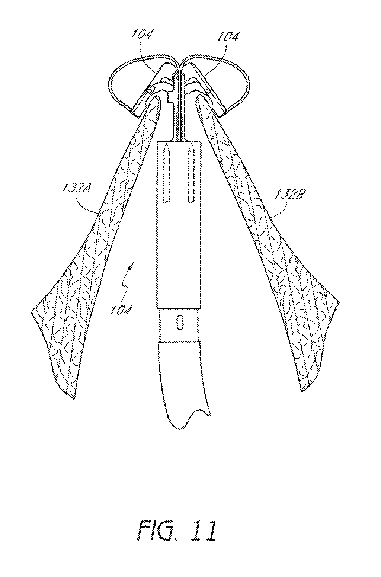
FIG. 11 is a schematic representation as in FIG. 10 with suture clasp arms positioned around first and second leaflets of the valve.
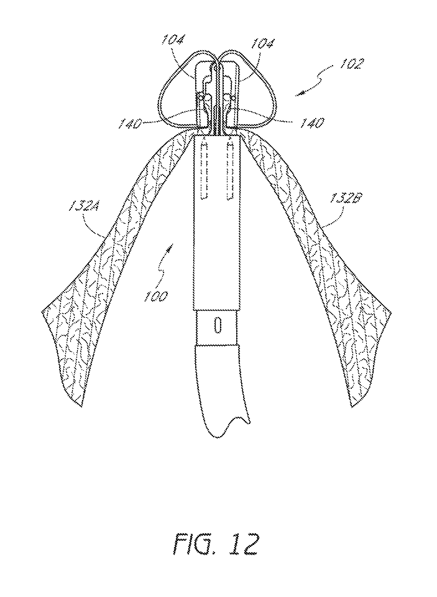
FIG. 12 is a schematic representation as in FIG. 11 with suture clasp arms retracted.
FIG. 13 is a schematic representation as in FIG. 12 showing suture catch mechanisms engaging the suture clasp arms.
FIG. 14 is a schematic representation as in FIG. 13 showing the suture catch mechanisms and suture portions retracted through the first and second leaflets.
FIG. 15 is a schematic representation as in FIG. 14 showing the suture portions extending through the first and second leaflets and being joined by a knot.
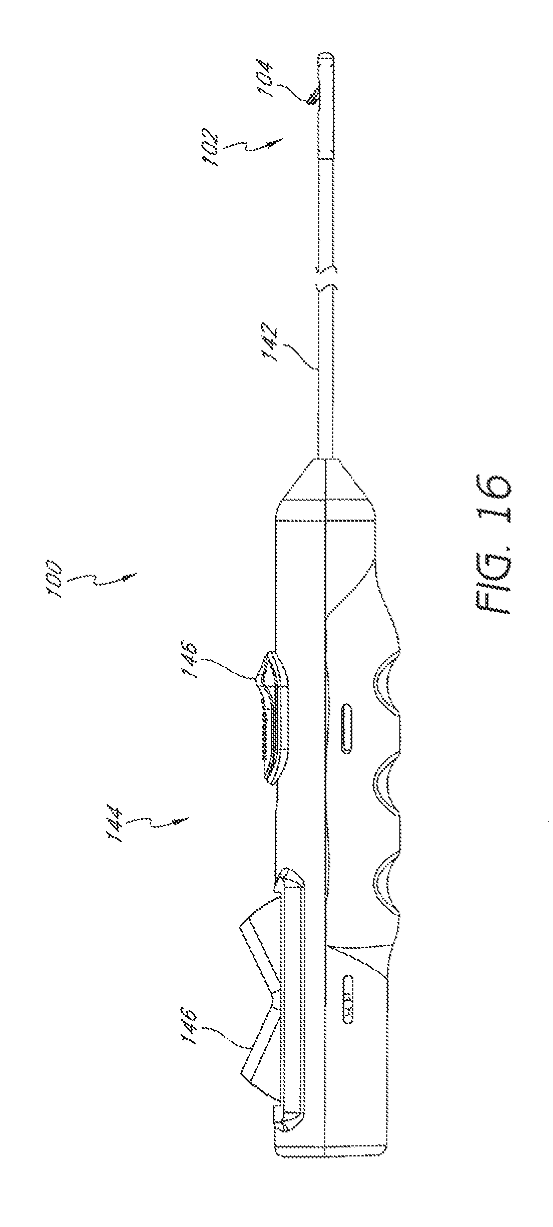
FIG. 16 is a plan view of an embodiment of a suturing device with a suture clasp arm in an extended position.
FIG. 17 is an enlarged perspective view of the distal end of the suturing device of FIG. 16 with the suture clasp arm in an extended position.
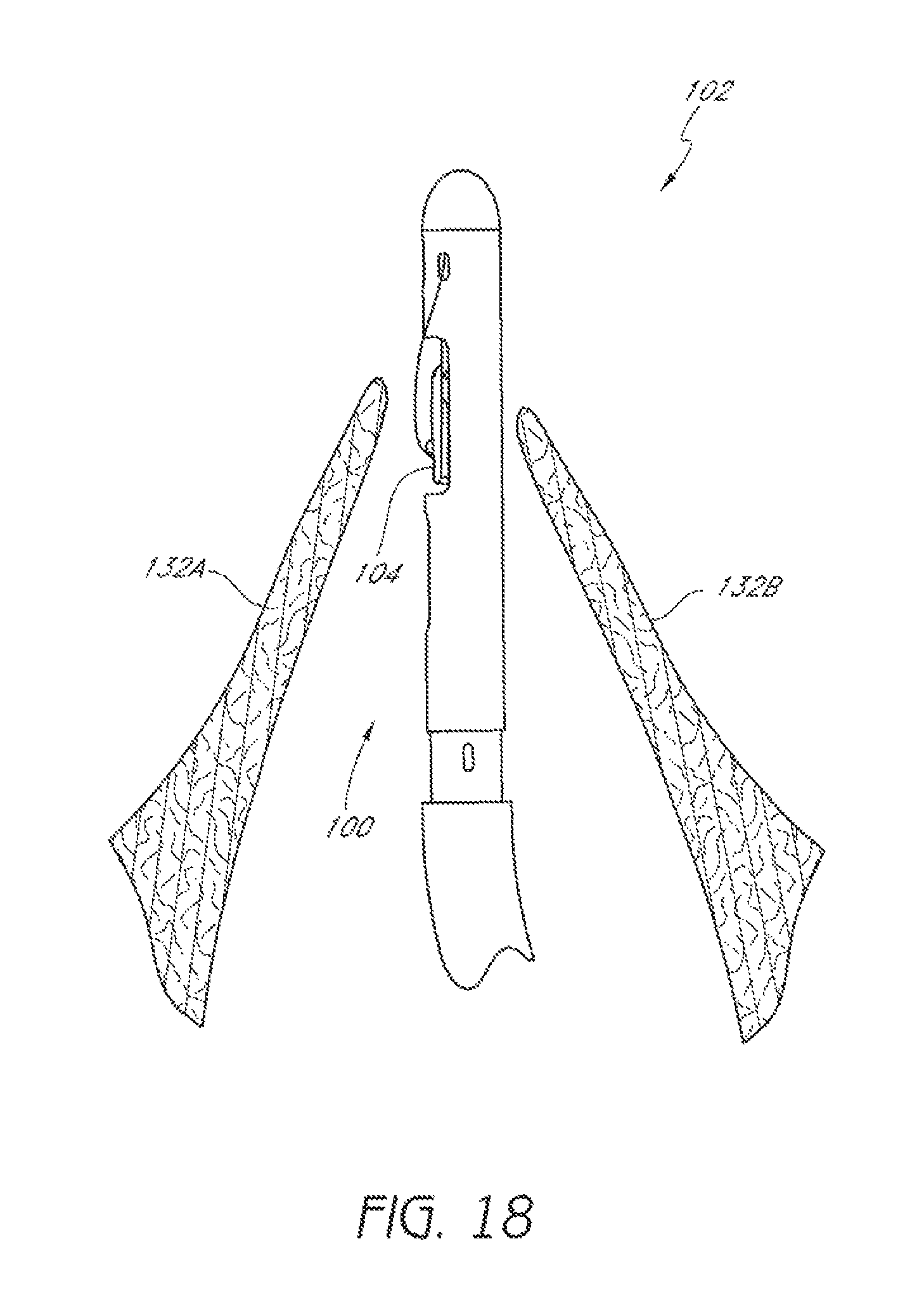
FIG. 18 is a schematic representation an embodiment of a first suturing device positioned in a passage through a valve.
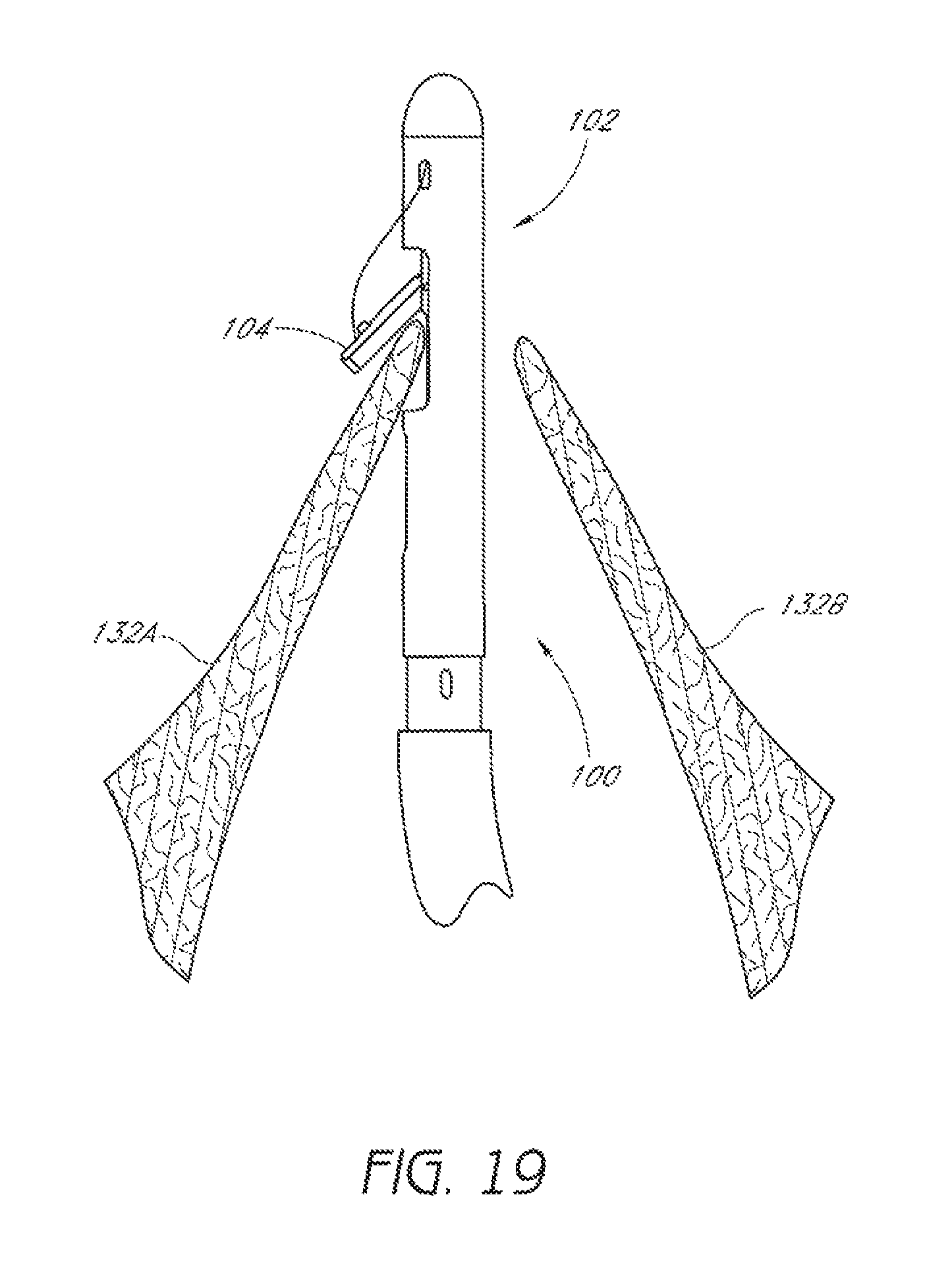
FIG. 19 is a schematic representation as in FIG. 18 with a suture clasp arm positioned around a first leaflet of the valve.
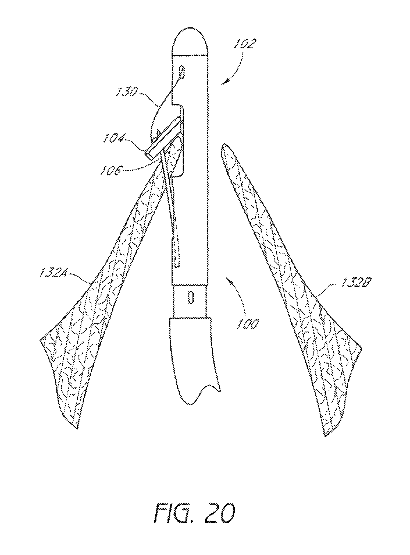
FIG. 20 is a schematic representation as in FIG. 19 showing a suture catch mechanism engaging the suture clasp arm.
FIG. 21 is a schematic representation as in FIG. 20 showing the suture catch mechanism and a suture portion retracted through the first leaflet.
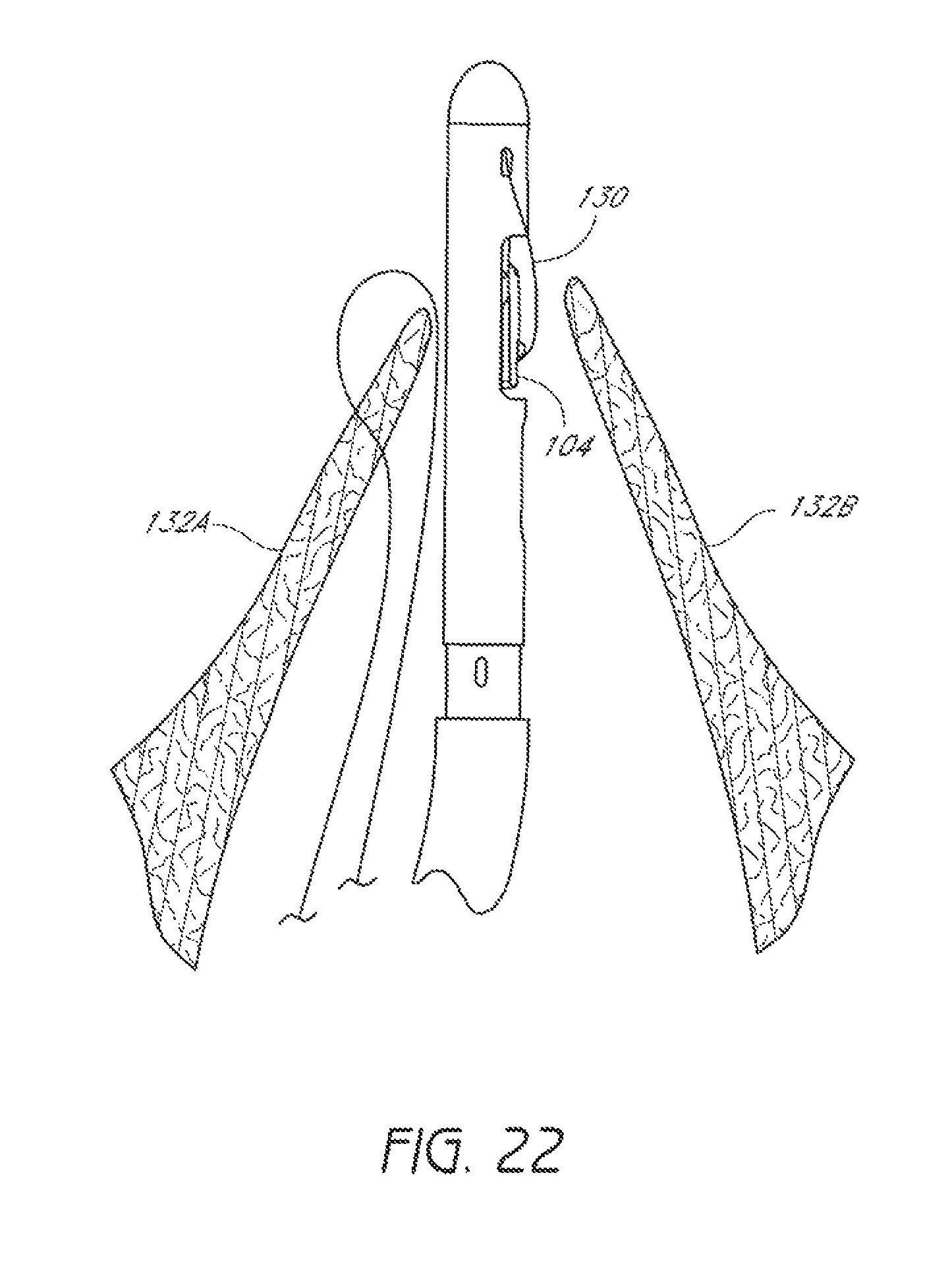
FIG. 22 is a schematic representation as in FIG. 21 showing a second suturing device positioned in the passage through the valve.
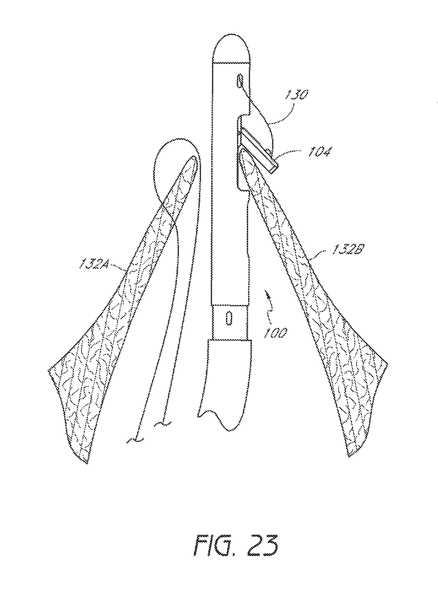
FIG. 23 is a schematic representation as in FIG. 22 with the suture clasp arm positioned around a second leaflet of the valve.
FIG. 24 is a schematic representation as in FIG. 23 showing a suture catch mechanism engaging the suture clasp arm.
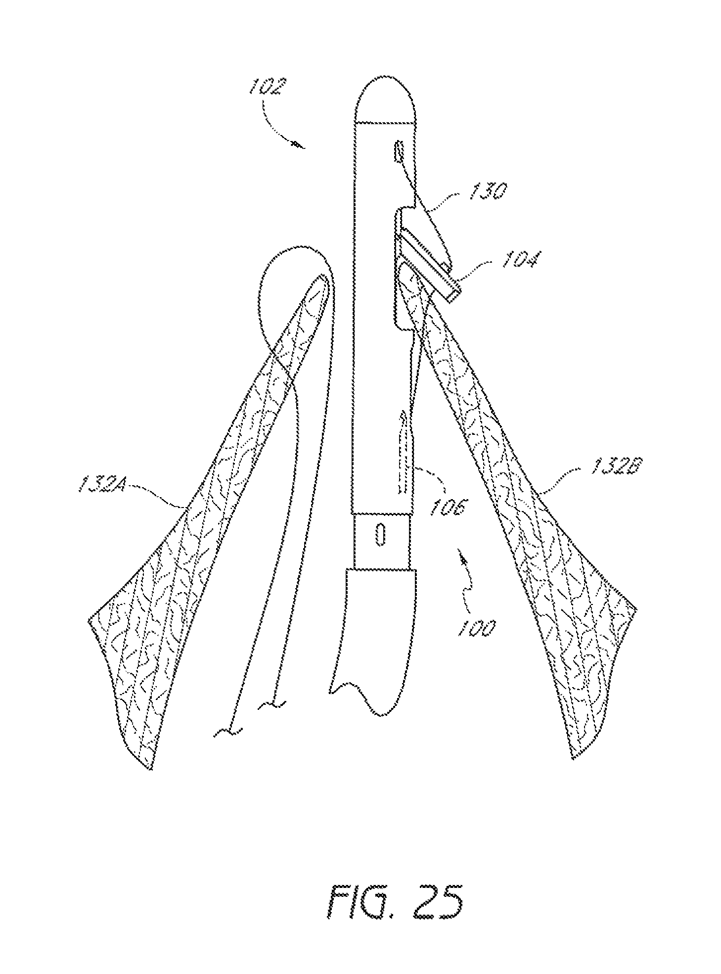
FIG. 25 is a schematic representation as in FIG. 24 showing the suture catch mechanism and a suture portion retracted through the second leaflet.
FIG. 26 is a schematic representation as in FIG. 25 showing the suture portions extending through the first leaflet and the second leaflet and being joined by a first knot.
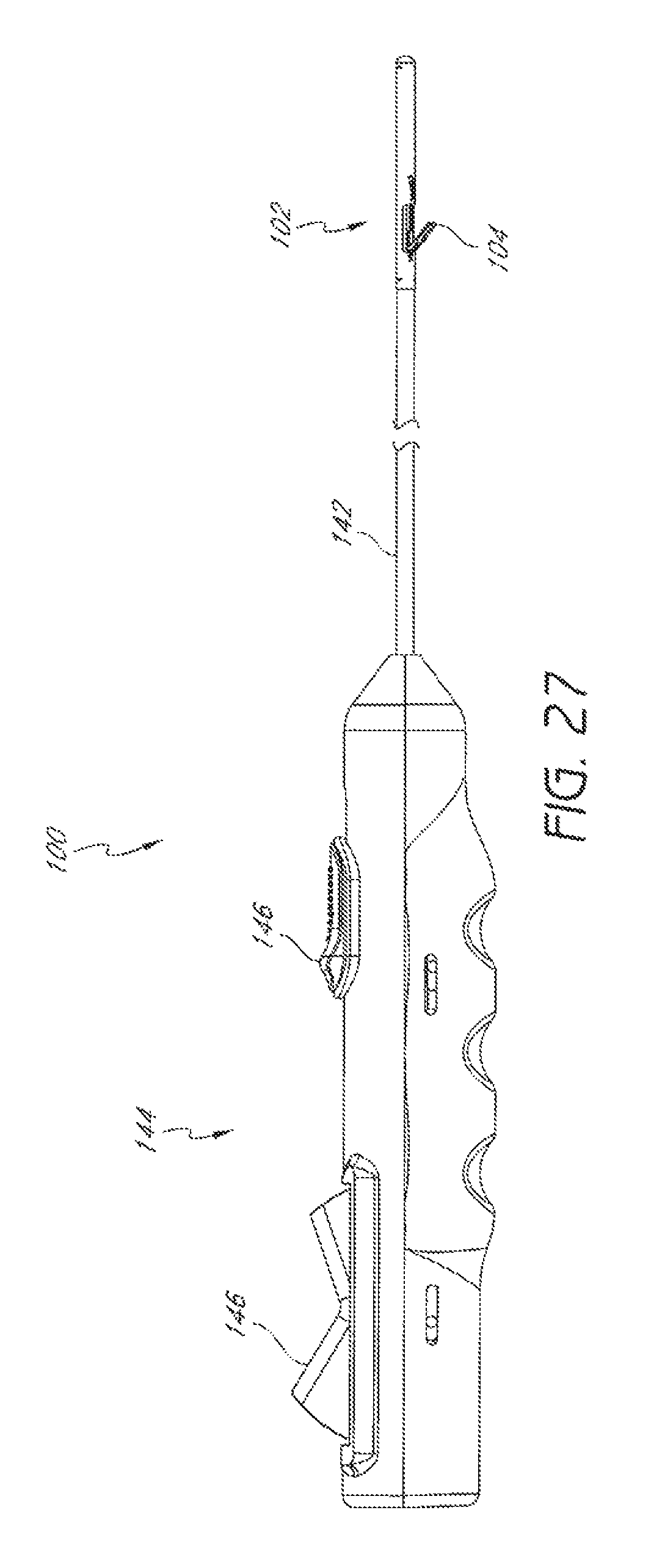
FIG. 27 is a plan view of an embodiment of a suturing device with a suture clasp arm in an extended position.
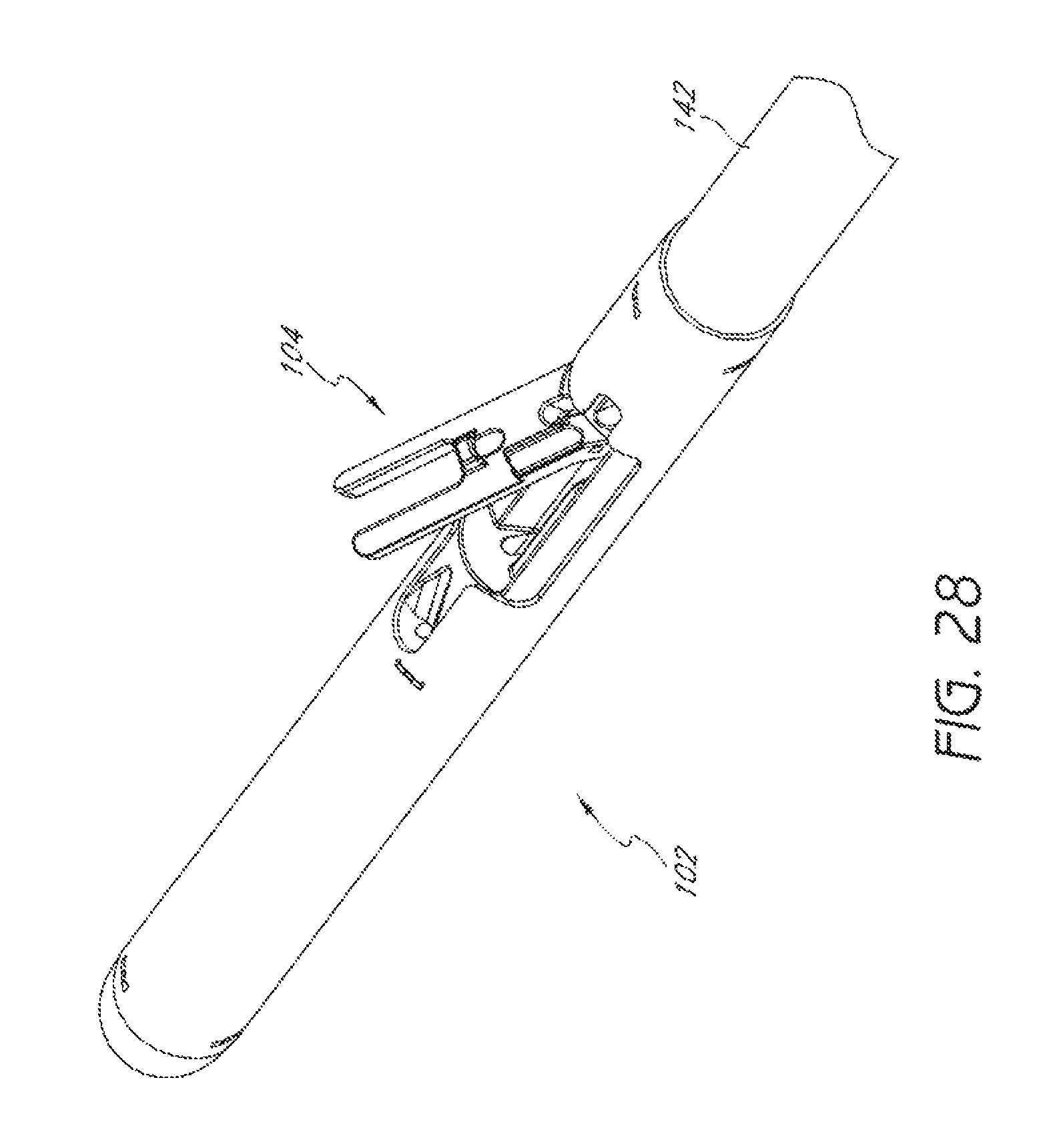
FIG. 28 is an enlarged perspective view of the distal end of the suturing device of FIG. 27 with the suture clasp arm in an extended position.
FIG. 29 is a schematic representation of an embodiment of a first suturing device positioned in a passage through a valve.
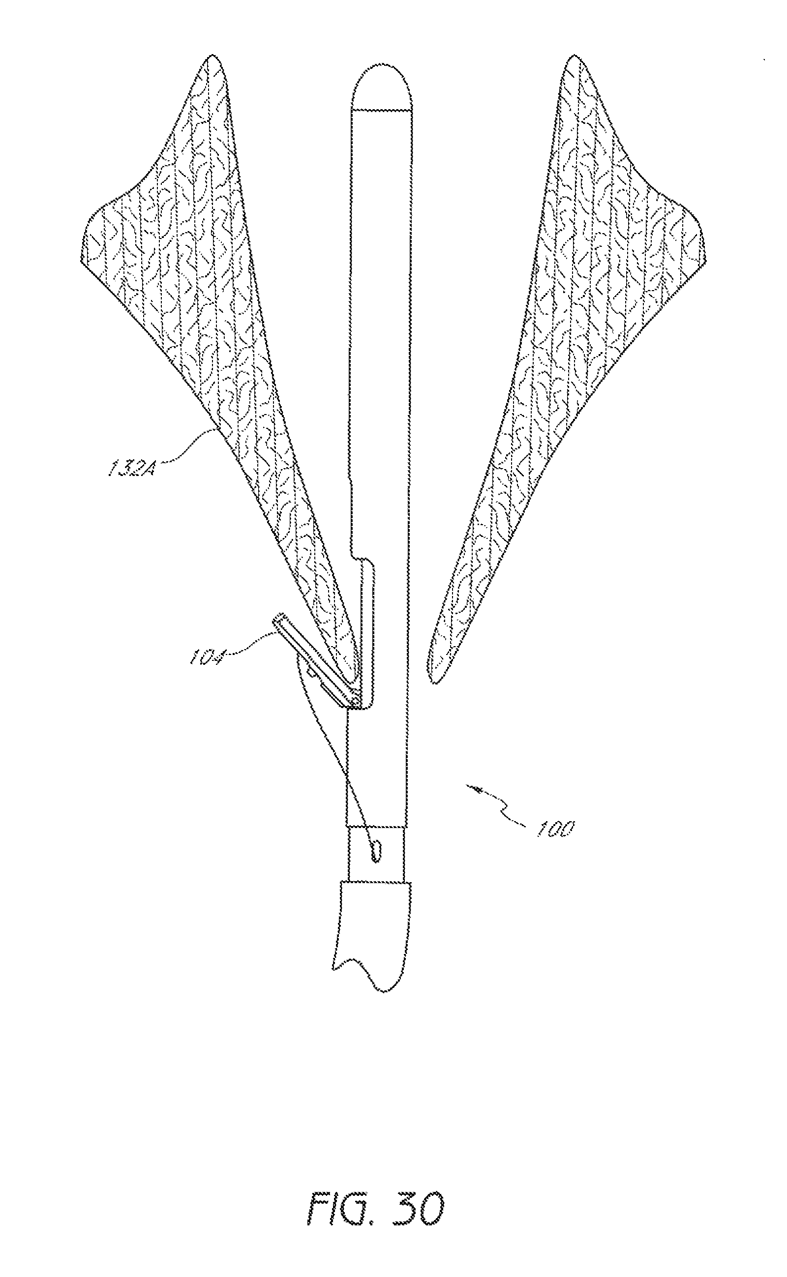
FIG. 30 is a schematic representation as in FIG. 29 with a suture clasp arm positioned around a first leaflet of the valve.
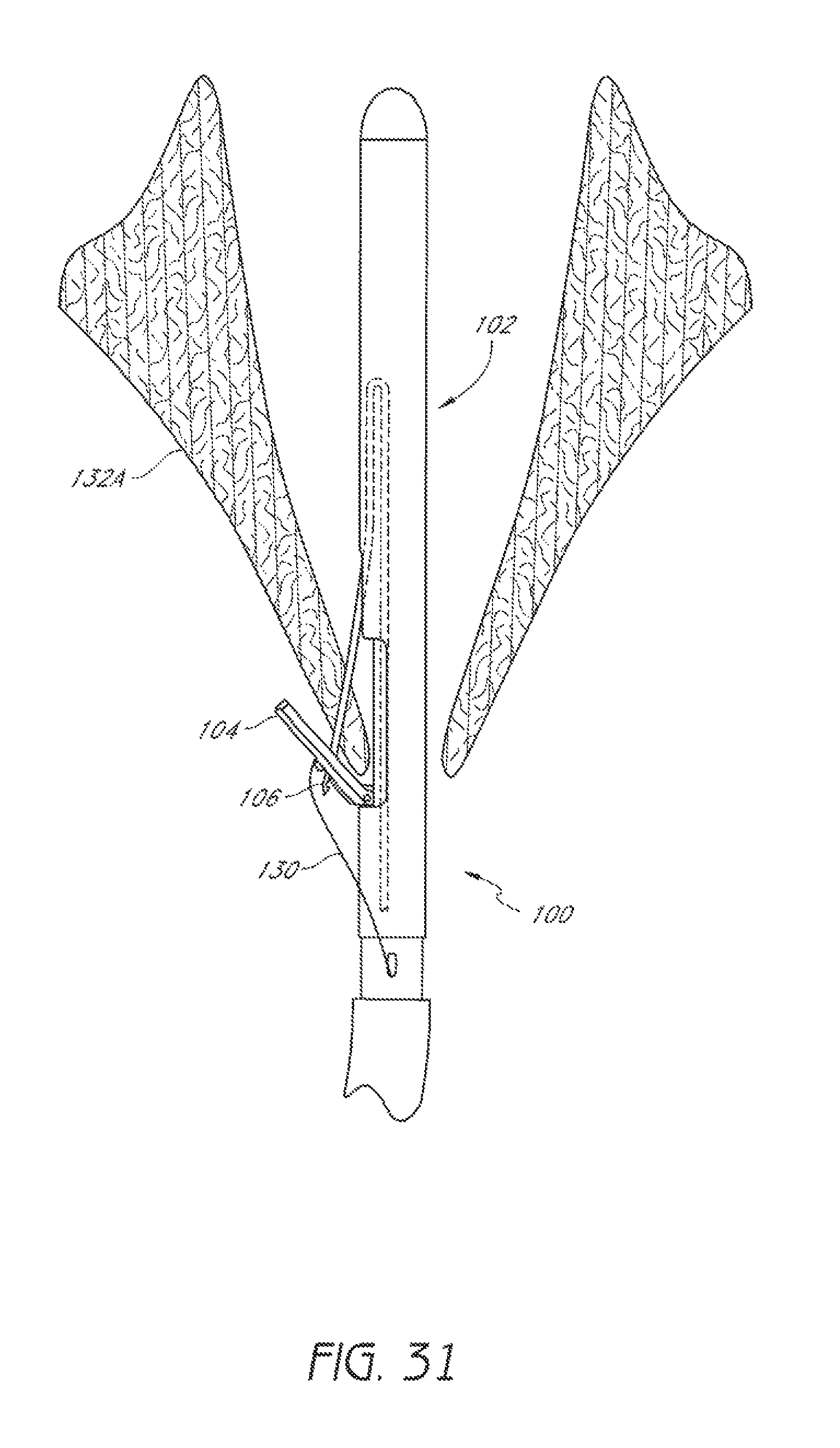
FIG. 31 is a schematic representation as in FIG. 30 showing a suture catch mechanism engaging the suture clasp arm.
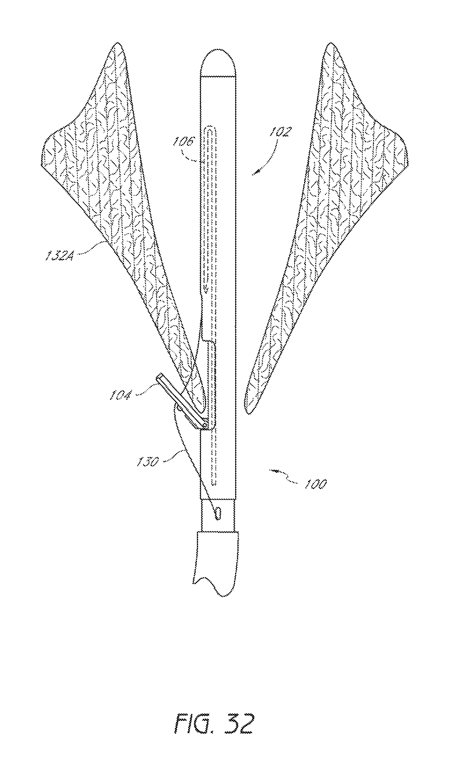
FIG. 32 is a schematic representation as in FIG. 31 showing the suture catch mechanism and a suture portion retracted through the first leaflet.
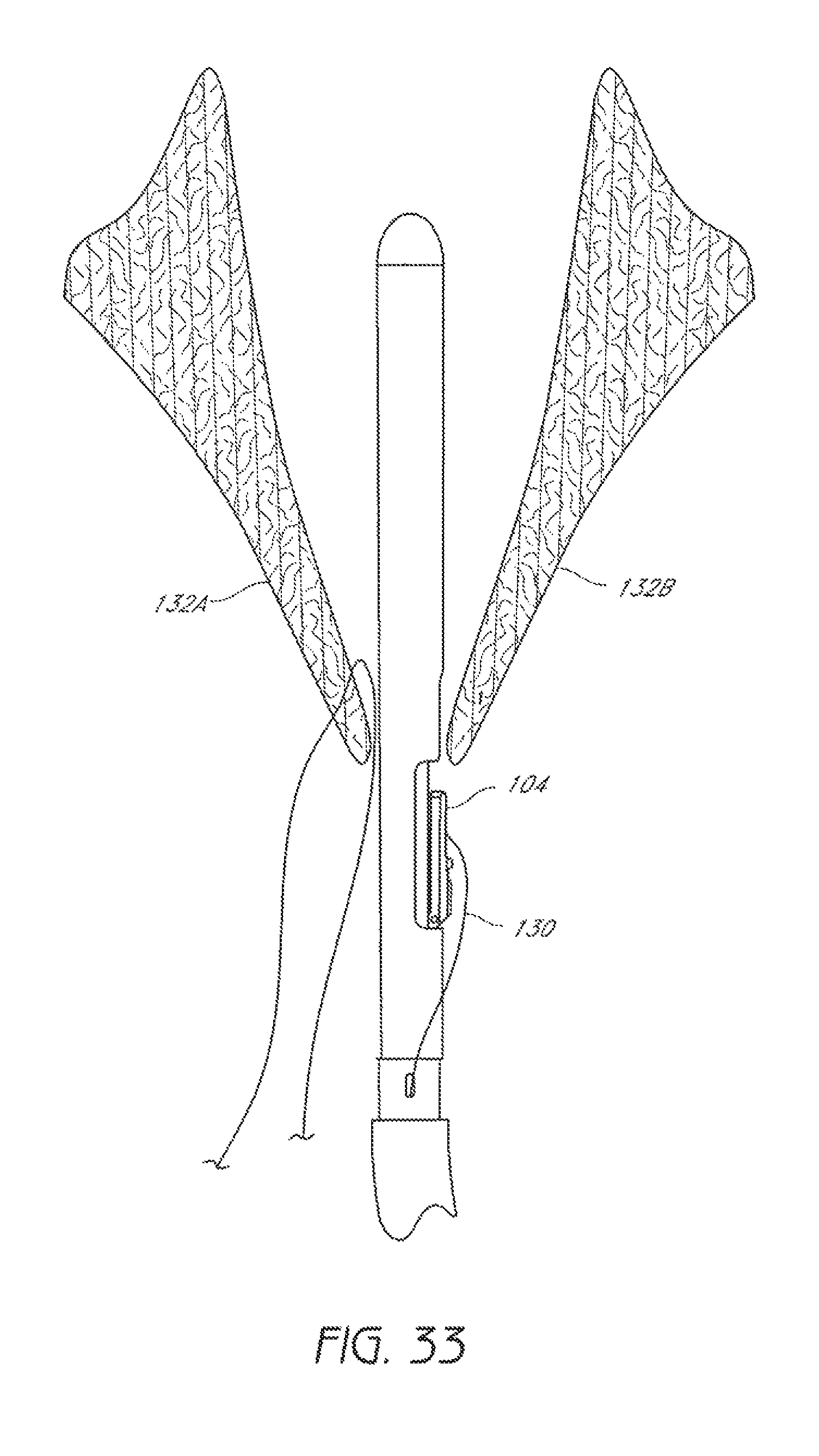
FIG. 33 is a schematic representation as in FIG. 32 showing a second suturing device positioned in the passage through the valve so as to permit a suture clasp arm to extend from the second suturing device.
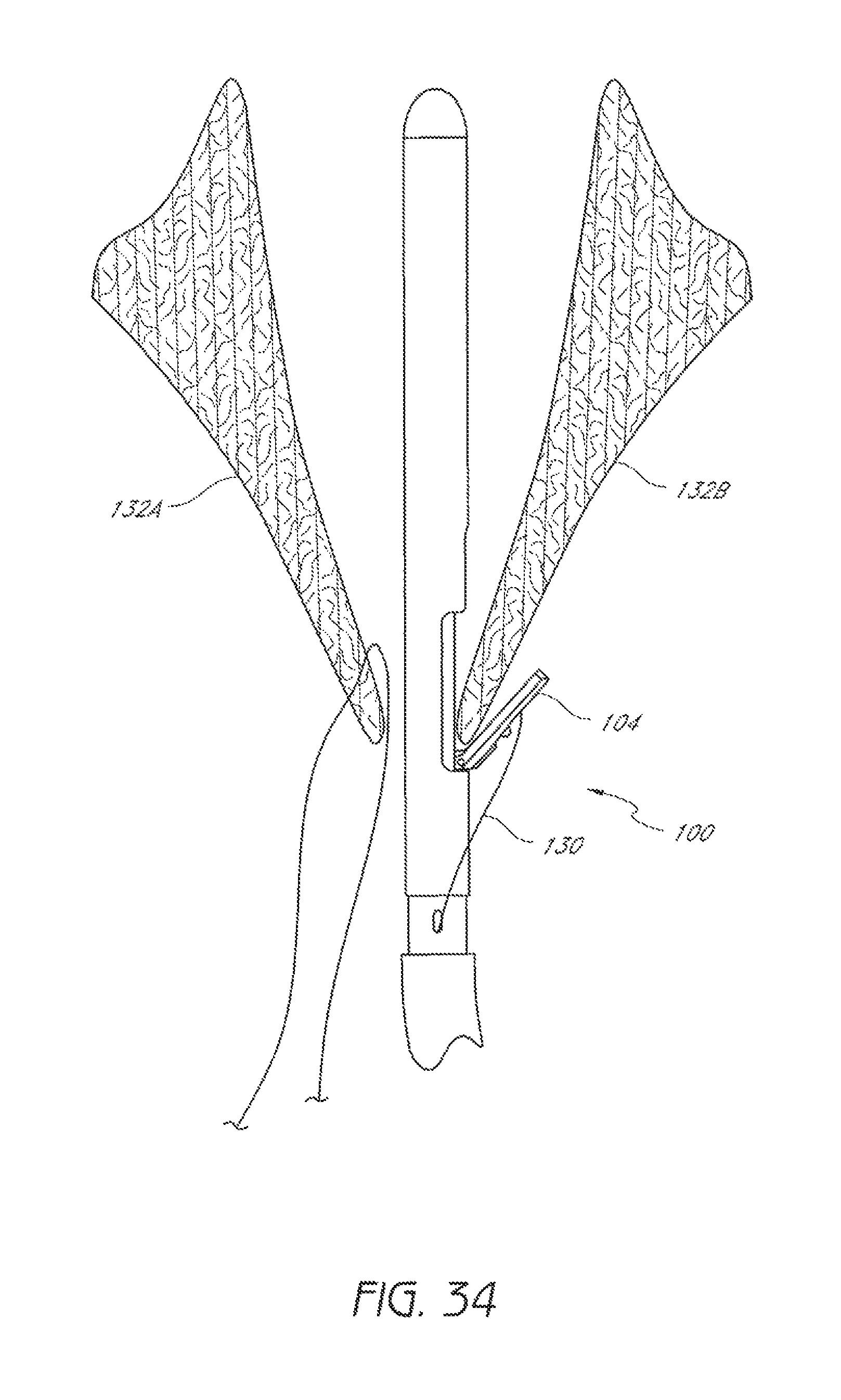
FIG. 34 is a schematic representation as in FIG. 33 with the suture clasp arm positioned around a second leaflet of the valve.
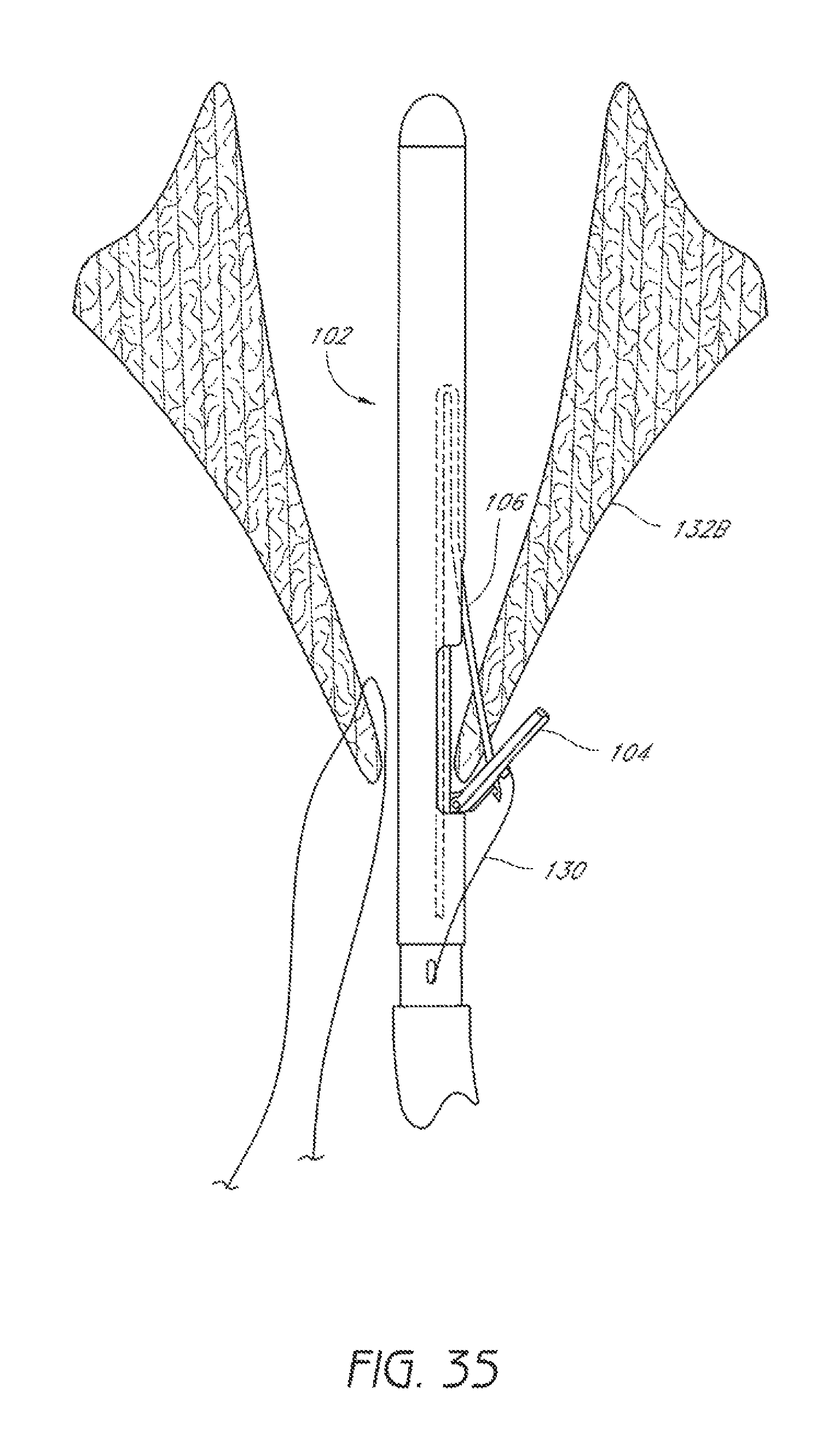
FIG. 35 is a schematic representation as in FIG. 34 showing a suture catch mechanism engaging the suture clasp arm.
FIG. 36 is a schematic representation as in FIG. 35 showing the suture catch mechanism and a suture portion retracted through the second leaflet.
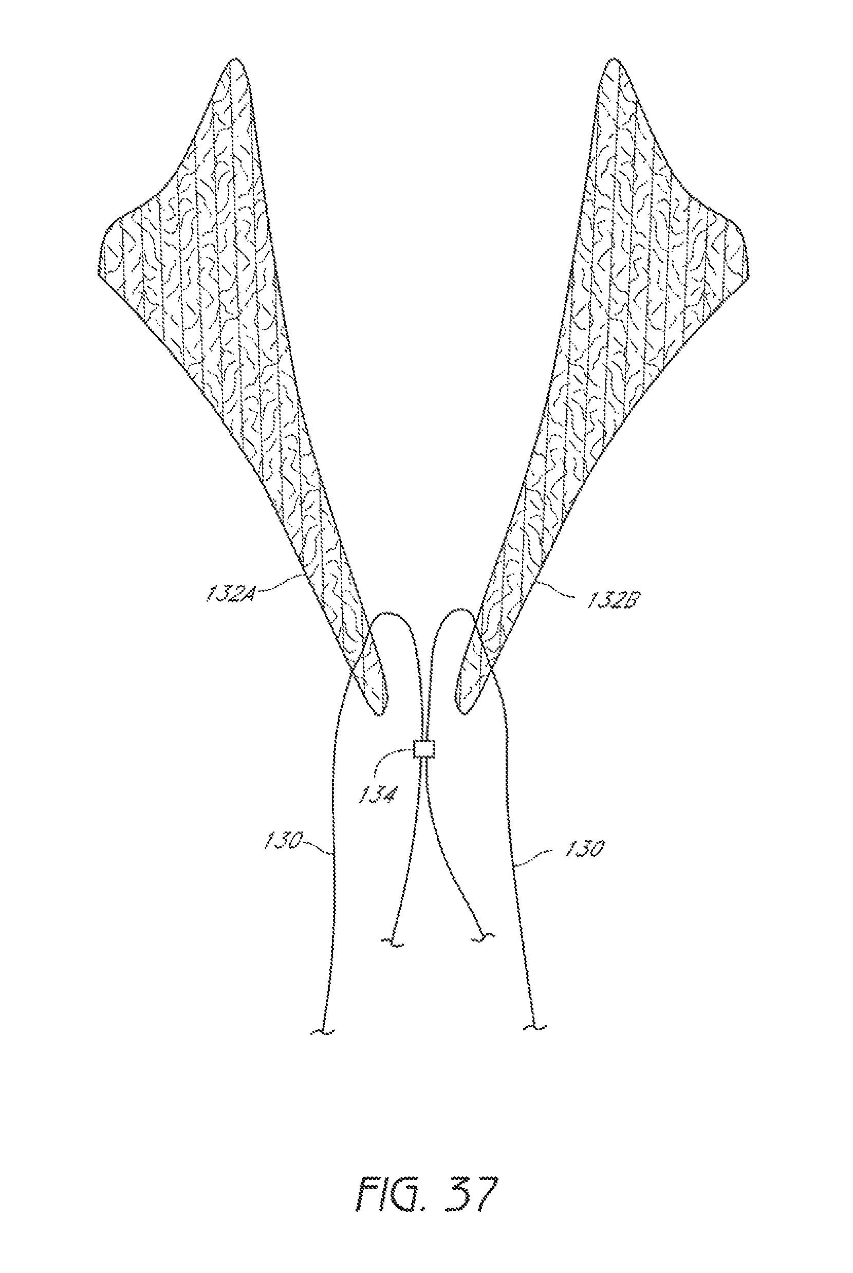
FIG. 37 is a schematic representation as in FIG. 36 showing the suture portions extending through the first leaflet and the second leaflet and being joined by a first knot.
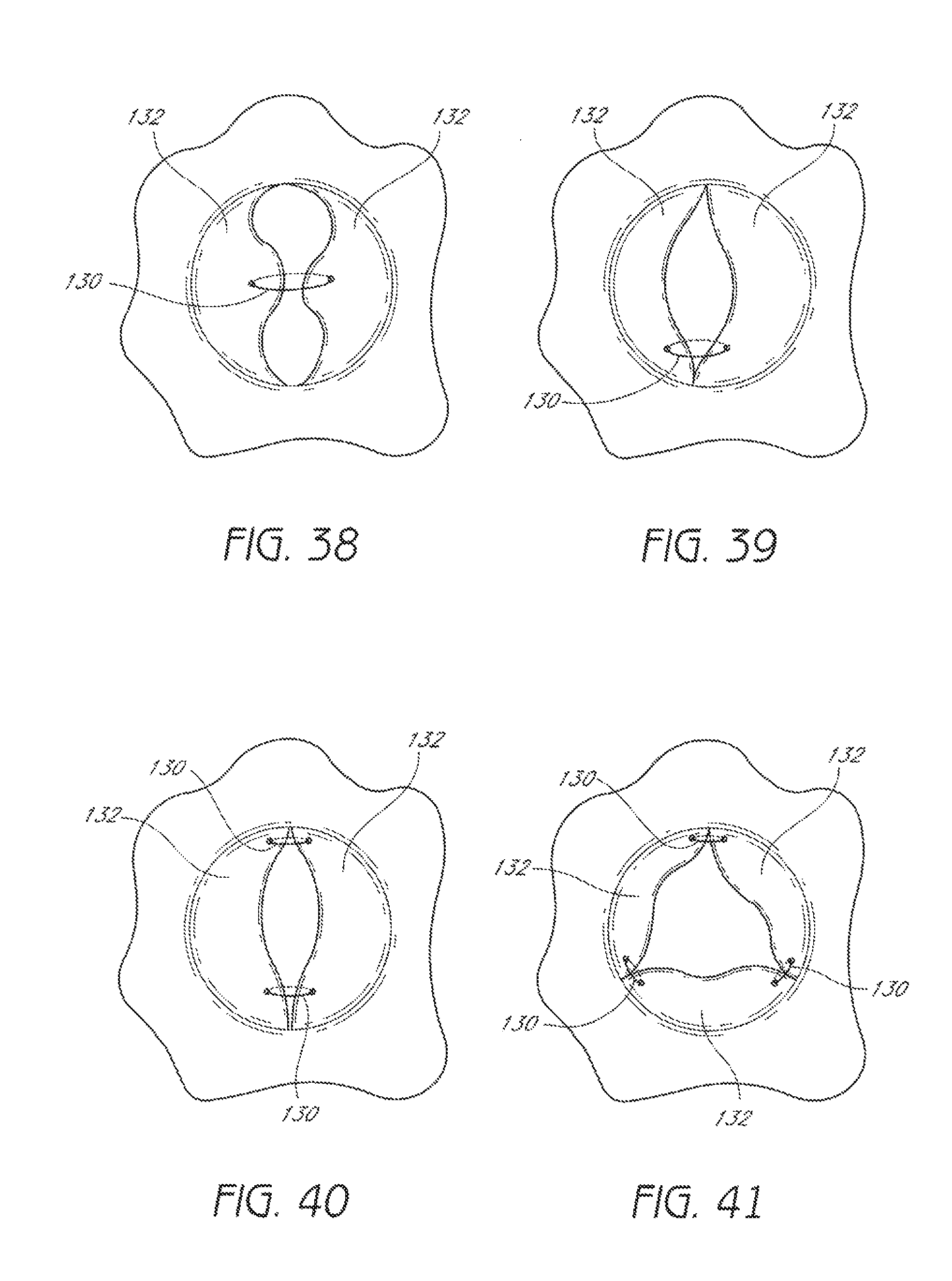
FIG. 38 illustrates placement of suture through a bicuspid valve near a central portion of each leaflet.
FIG. 39 illustrates placement of suture through a bicuspid valve at locations spaced from the center of each leaflet.
FIG. 40 illustrates placement of suture through a bicuspid valve at multiple locations spaced from the center of each leaflet.
FIG. 41 illustrates placement of suture through a tricuspid valve.
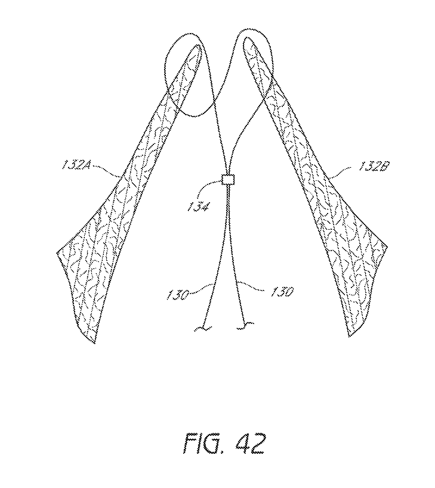
FIG. 42 illustrates placement of suture through a valve.
FIG. 43 illustrates placement of suture through a valve.
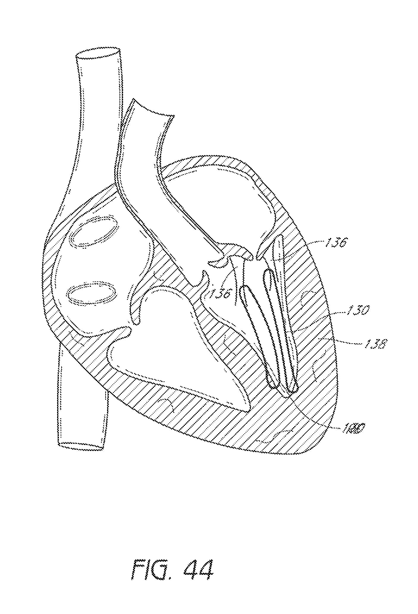
FIG. 44 illustrates placement of suture through chordae tendineae and myocardium.
DETAILED DESCRIPTION OF SPECIFIC EMBODIMENTS
Embodiments of suturing devices and methods for suturing biological tissue are disclosed herein. The suturing devices and their methods of use can be useful in a variety of procedures, such as treating (e.g., closing) wounds and naturally or surgically created apertures or passageways. For example, the suturing devices can be used to treat an anatomical valve, such as a heart valve, including heart valves that may be weakened or stretched, or have other structural defects, such as congenital defects, that cause them to close improperly. In some embodiments, one or more suturing devices can be used to treat or repair valves, such as the tricuspid, pulmonary, mitral, and aortic valves, for example. In some embodiments, one or more suturing devices can be used to perform procedures such as the Alfieri technique (edge-to-edge repair), replacement of the chordae tendineae, shortening of the chordae tendineae, patch application, leaflet reshaping, and attachment of prosthetics, such as rings and biological or mechanical replacement valves, for example.
In some embodiments, the suturing devices can be used to close or reduce a variety of other tissue openings, lumens, hollow organs or natural or surgically created passageways in the body. In some embodiments, the suturing devices can be used to suture prosthetics, synthetic materials, or implantable devices in the body. For example, the devices can be used to suture pledget within the body.
FIG. 1 illustrates an exemplifying use environment for suturing an aortic valve 4. Adaption of the devices and methods disclosed herein for suturing a heart valve may also be made with respect to procedures for suturing other bodily tissue and procedures for suturing prosthetics, synthetic materials, or implantable devices in the body. As depicted by FIG. 1, a guidewire 10 can be advanced through the aorta 2 to a position at or near the aortic valve 4. The guidewire 10 can be advanced into the aorta 2 through a subclavian artery (not shown). It is anticipated that the heart may be accessed through any of a variety of pathways. For example, the heart may be accessed through the inferior vena cava 3, the superior vena cava 5, or other vascular access. With the guidewire 10 in place, the physician can insert a sheath 12 to a position at or near the aortic valve 4. This sheath 12 is typically a single lumen catheter with a valve on its proximal end. The valve can be used, for example, to prevent extraneous bleed back or to introduce medication into the patient's body. A suturing device, such as those described further below, can then be advanced through the lumen of the sheath 12. In an alternative embodiment, the suturing device can be advanced over the guidewire 10 and positioned at or near the aortic valve 4 without the need to insert an introducer sheath 12.
FIG. 2 illustrates another exemplifying use environment for suturing a mitral valve 8. As depicted by FIG. 2, a guidewire 10 is advanced into the left ventricle 6 of the heart through a puncture or incision 9 near an apex 7 of the left ventricle 6. The heart may be accessed through a limited thoracotomy, small trocar puncture, or small catheter puncture. Other access paths may be used. The guidewire 10 can then be further positioned at or near the mitral valve 8. With the guidewire 10 in place, the physician can insert a sheath 12 to the left ventricle 6. The sheath 12 can be placed at or near the mitral valve 8. The suturing device can then be advanced through the lumen of the sheath 12. In an alternative embodiment, the suturing device can be advanced over the guidewire 10 and positioned at or near the mitral valve 8 without the need to insert an introducer sheath 12.
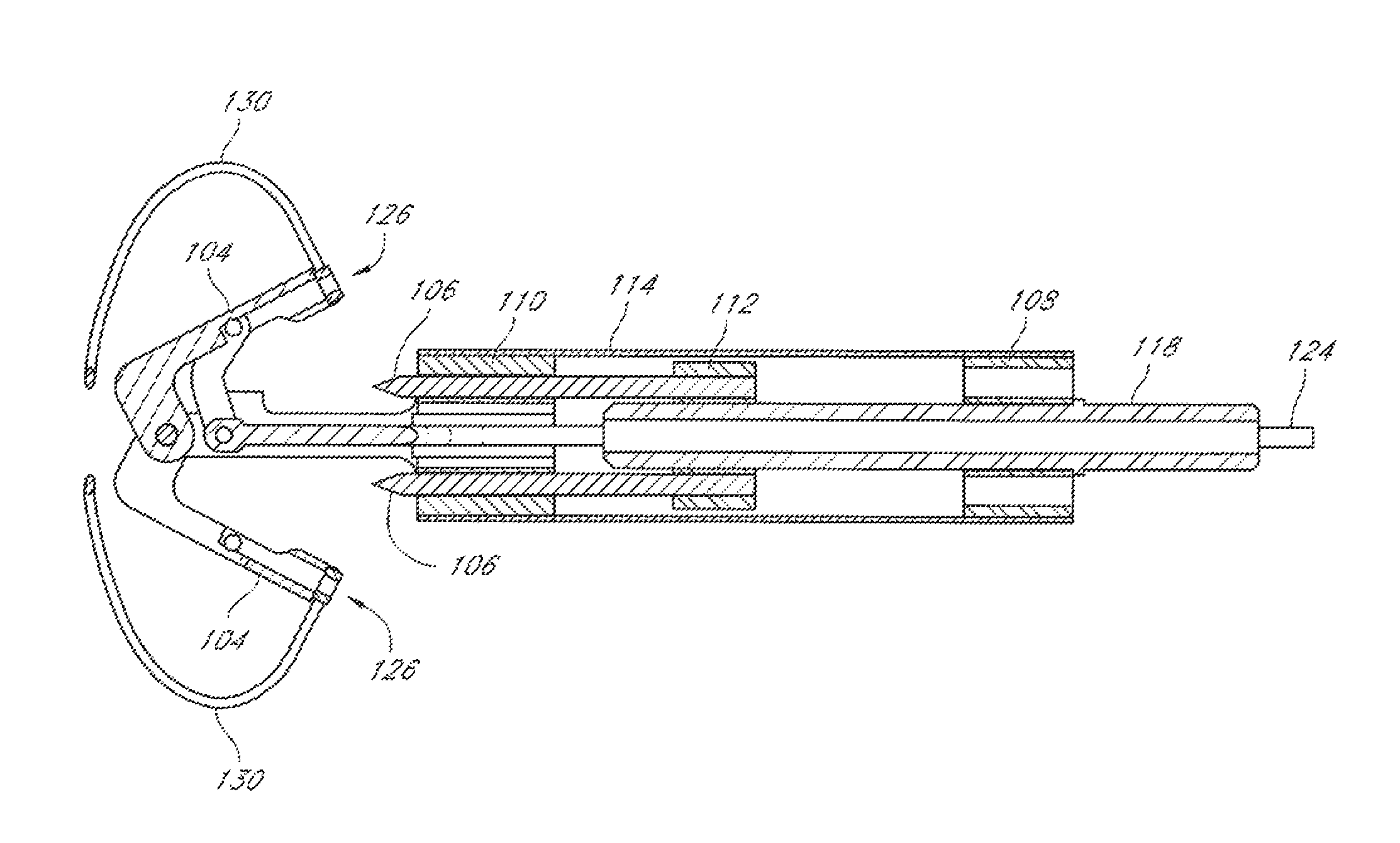
FIGS. 3-9 illustrate an embodiment of a suturing device 100 that can be used to suture an anatomical valve, such as a heart valve. While the device 100 will be described with reference to suturing an anatomical valve, such as a heart valve, the device 100 could be used to suture other biological tissue and implantable devices and materials. The suturing device 100 can comprise a distal assembly 102, one or more suture clasp arms 104, and one or more suture catch mechanisms 106. The suturing device 100 can further comprise an elongate member (not shown) to facilitate manipulation of the suture clasp arm(s) 104 and the suture catch mechanism(s) 106 from a remote location. For example, the elongate member can comprise one or more lumens to accommodate a length of suture, or one or more actuator rods for manipulating the suture clasp arm(s) 104 and the suture catch mechanism(s) 106, or both. In some embodiments, the distal assembly 102 can comprise a portion of the elongate member.
The distal assembly 102 can comprise a proximal mount 108, distal mount 110, a hub 112, and a casing 114 (FIG. 6). The proximal mount 108 can be fixedly connected to the distal mount 110 by the casing 114. The hub 112 can be positioned within the casing 114 for sliding movement between the proximal mount 108 and the distal mount 110.
The proximal mount 108 can be connected to the elongate member (not shown). Alternatively, a distal end of the elongate member can form or be integrally formed with the proximal mount 108. In some embodiments, the elongate member can comprise the casing 114. The proximal mount 108 can comprise one or more lumens 116, as shown in FIGS. 3 and 5.
The hub 112 can be fixedly connected to the suture catch mechanism(s) 106 and an actuator rod 118. The actuator rod 118 can move through a lumen 116 in the proximal mount 108. Accordingly, distal advancement of the actuator rod 118 causes distal advancement of the suture catch mechanism(s) 106. The hub 112 can comprise one or more lumens 120.
The suture clasp arm(s) 104 can be pivotally connected to the distal mount 110 such that the suture clasp arm(s) 104 can move between a retracted position, illustrated in FIGS. 3-4, and an extended position, illustrated in FIGS. 5-7A. Although the arms 104 of the device 100 that is illustrated in FIGS. 3-9 pivot about a distal end of the arms 104, the arms 104 can pivot about a proximal end of the arms 104 in other embodiments.
The suture clasp arm(s) 104 can be connected to an actuator rod 124, which can move through a lumen 116 in the proximal mount 108. The arm(s) 104, the distal mount 110, and the rod 124 can be connected such that distal movement of the rod 124 causes the arm(s) 104 extend and proximal movement of the rod 124 causes the arm(s) 104 to retract. In some embodiments, the arm(s) 104 can extend to a position that is substantially perpendicular to their fully-retracted position. In other embodiments, the arm(s) 104 can move less than 90.degree. between the fully-retracted position and the fully-extended position.
The distal mount 110 can comprise one or more lumens 122 (FIG. 5) to allow movement of the suture catch mechanism(s) 106 through the distal mount 110. Additionally or alternatively, the one or more lumens 122 can accommodate a length of suture, the actuator rod 124, or both.
The suture clasp arm(s) 104 can have suture clasps 126 to releasably hold a suture portion 130. The suture catch mechanism(s) 106 can be advanced to engage the suture portion(s) 130 held by the suture clasp arms(s). Once the suture catch mechanism(s) 106 have engaged the suture end portion(s) 130, the suture catch mechanism(s) 106 can be retracted to pull the suture ends from the suture claps 126.
In some embodiments, the suture clasps 126 can be positioned on the suture clasp arm 104 such that the suture catch mechanism 106 retrieves the suture end portion 130 retained in the suture clasp 126 while the suture clasp arm 104 is at least partially retracted from its fully-extended position. In some embodiments, the suture clasps 126 can be positioned on the suture clasp arm 104 such that the suture catch mechanism 106 retrieves the suture end portion 130 retained in the suture clasp 126 while the suture clasp arm 104 is fully retracted. In some embodiments, the suture catch mechanism 106 can be advanced in a continuously longitudinal direction to engage the suture clasp 126 of the suture clasp arm 104 while the suture clasp arm is fully retracted. In some embodiments, the suture clasp 126 can be located on a proximally-facing side of a suture clasp arm 104 that pivots about a distal end of the suture clasp arm. In some embodiments, the suture clasp 126 can be located on a distally-facing side of a suture clasp arm 104 pivots about a proximal end of the suture clasp arm.
In some embodiments, the suture clasp arm 104 can be configured to receive a tissue-piercing portion of the corresponding suture catch mechanism 106. For example, in some embodiments, when the suture catch mechanism 106 is fully advanced, the tissue-piercing portion can be fully received with the corresponding suture clasp arm 104. In some embodiments, the suture clasp arm 104 can receive the tissue-piercing portion of the suture catch mechanism 106 when the arm is at least partially closed. In some embodiments, suture clasp arm 104 can receive the tissue-piercing portion of the suture catch mechanism 106 when the arm is fully retracted.
In some embodiments, the device 100 can comprise a recess 140 between the suture clasp arm 104 and the distal mount 110, or other component of the distal assembly 102, when the suture clasp arm 104 is fully retracted, as illustrated in FIG. 7B. In some embodiments, a tissue portion, such as a valve leaflet, can be received with the recess 140 with the suture clasp arm 104 fully retracted and without damaging the tissue portion. In some embodiments, the tissue portion can be held in the recess 140 by the suture clasp arm 104 while the suture clasp arm is fully retracted. In some embodiments, the tissue portion can be held in the recess 140 by the suture clasp arm 104 while the suture clasp arm is at least partially retracted.
In some embodiments, the recess 140 can have a size and shape to receive a leaflet of a valve between the elongate body and the arm when the arm is at least partially retracted without damaging the leaflet. In some embodiments, the recess 140 can have a size and shape to receive a leaflet of a valve between the elongate body and the arm when the arm is fully retracted without damaging the leaflet. In some embodiments, the recess 140 can have a size and shape to retain the leaflet between the elongate body and the arm when the arm is at least partially retracted without damaging the leaflet. In some embodiments, the recess 140 can have a size and shape to retain the leaflet between the elongate body and the arm when the arm is fully retracted without damaging the leaflet.
In some embodiments, the device 100 can be manipulated with the suture clasp arm(s) 104 in the extended position to place a tissue portion, such as a leaflet of a valve, between the suture clasp arm 104 and the distal mount 110, as shown, for example, in FIG. 11. In some embodiments, the suture clasp arm 104 can be at least partially closed about the tissue portion. In some embodiments, the suture clasp arm 104 can be fully closed about the tissue portion. In some embodiments, the suture clasp arm 104 can be at least partially retracted to securely hold the tissue portion between the suture clasp arm 104 and the distal mount 110. In some embodiments, the suture clasp arm 104 can be moved to the retracted position to securely hold the tissue portion between the suture clasp arm 104 and the distal mount 110, as shown, for example, in FIG. 12. In some embodiments, the tissue portion is not damaged by closing the suture clasp arm 104 about the issue portion or holding the tissue portion between the suture clasp arm 104 and the distal mount 110.
With the tissue portion held between the arm 104 and the distal mount 110, the corresponding suture catch mechanism 106 can be advanced to engage the suture portion 130 held by the suture clasp 126 of the arm 104, as shown, for example, in FIG. 13. The suture portion 130 can then be drawn through the tissue portion by the suture catch mechanism 106, as shown, for example, in FIG. 14. In other embodiments, the suture catch mechanism(s) 106 can be advanced toward the suture clasp arm(s) 104 and retrieve the suture ends from the suture clasps 126 when the arm(s) 104 are in the extended position. In some embodiments, the suture catch mechanism can be a needle.
In some embodiments, the distal assembly 102 can comprise a tube or conduit 128 to accommodate a suture and prevent damage to the suture by any component of the device 100. In some embodiments, the conduit 128 extends through a lumen 116 in the proximal mount 108, a lumen 120 in the distal mount 110, and a lumen 122 in the hub 112.
Further details regarding devices, structures, and methods that may be incorporated with the above embodiments are provided in U.S. Pat. No. 7,090,686 and U.S. Patent Application Publication No. 2008/0269786, published on Oct. 30, 2008, the entireties of all of which are hereby incorporated by reference herein and form a part of this specification. For example, in some embodiments having plural arms 106 and plural suture catch mechanisms 106, each arm 104 and each suture catch mechanism 106 of the device 100 can be independently actuated to move individually between the retracted position and the extended position.
FIGS. 10-15 illustrate a method for suturing an anatomical valve according to one embodiment. The distal end of a suturing device 100 can be positioned between leaflets 132 of a valve, as shown in FIG. 10. The device 100 can be advanced through the vasculature to the desired position. For example, the device 100 can be advanced through the inferior vena cava into right atrium and through the septum and positioned in the passage through the mitral valve 8 (FIG. 2).
The suturing device 100 can be advanced to allow suture clasp arms 104 to extend from the distal assembly 102. The suture clasp arms 104 can then be extended and the device 100 can be retracted until the suture clasp arms 104 extend around a first leaflet 132A and a second leaflet 132B of the valve, as shown in FIG. 11.
Once the suture clasp arms 104 have been properly positioned around the first and second leaflets 132, the suture clasp arms 104 can be retracted to trap portions of the first and second leaflets 132, for example between the suture clasp arms 104 and the distal mount 110 in the recess 140, as illustrated in FIG. 12.
With the first and second leaflets 132 trapped the suture catch mechanisms 106 can be advanced from the distal assembly 102 to penetrate the first and second leaflets 132 and engage the suture portions 130 held by the suture clasp arms 104, as illustrated in FIG. 13.
After the suture portions 130 has been engaged, the suture catch mechanisms 106 and engaged suture portions 130 are then retracted through the tissue of the first and second leaflets 132 into the distal assembly 102, as shown in FIG. 14. The suture clasp arms 104 can be extended to release the first and second leaflets 132. After the first and second leaflets have been released, the device 100 can be advanced slightly so that the suture clasp arm 104 can be moved to the retracted position without pinching the leaflets 132. The first suturing device 100 can then be withdrawn from the valve.
As shown in FIG. 15, after the suturing device 100 has been withdrawn, the suture portions 130 extend from the leaflets 132. The suture portions 130 can be pulled to draw the first leaflet 132A and the second leaflet 132B towards one another. The suture portions 130 can then be secured together to limit movement of the leaflets 132A, 132B relative to one another, as illustrated in FIG. 15 for example. In some embodiments, the sutures 130 can hold a portion of the leaflets 132A, 132B in contact with one another. In other embodiments, the sutures 130 merely hold the leaflets 132A, 132B in closer proximity to one another than they had previously been. The suture portions 130 can be secured together by tying a knot 134 according to any known method or by applying a knot 134, such as described in U.S. Patent Publication No. 2007/0010829 A1, published Jan. 11, 2007, the entirety of which is hereby incorporated herein by reference. The suture portions 130 can be secured together exterior to the body or within the body. Any excess portion of sutures 130 can be trimmed.
FIGS. 16 and 17 illustrate an embodiment of a suturing device 100 that can be used to suture an anatomical valve, such as a heart valve. The suturing device 100 can comprise a distal assembly 102, a single suture clasp arm 104, and a single suture catch mechanism 106.
As illustrated in FIGS. 16 and 17, the suturing device 100 can comprise an elongate member 142 to facilitate manipulation of the suture clasp arm 104 and the suture catch mechanism 106 from a remote location. For example, the elongate member can comprise one or more lumens to accommodate a length of suture, or one or more actuator rods for manipulating the suture clasp arm 104 and the suture catch mechanism 106, or both. The suturing device 100 can comprise a handle 144 with one or more actuators and/or pulls 146 for moving the suture clasp arm 104 and the suture catch mechanism 106. Further details regarding handles and associated components, including actuator rods, are provided in U.S. Patent Application Publication No. 2008/0269786, published on Oct. 30, 2008, the entirety of which is hereby incorporated by reference herein and forms a part of this specification.
In some embodiments, the suture clasp arm 104 can pivot about an axis located at a distal end of the suture clasp arm 104 when the suture clasp arm 104 is in a retracted position, as illustrated in FIGS. 16 and 17.
FIGS. 18-26 illustrate a method according to one embodiment for suturing an anatomical valve. Although the illustrated method involves two devices 100, each having a single suture clasp arm 104 and a single suture catch mechanism 106, the illustrated method can also be practiced using a single suturing device 100 having more than one arm 104 and more than one suture catch mechanism 106.
The distal end of a first suturing device 100 can be positioned between leaflets 132 of a valve, as shown in FIG. 18. The device 100 can be advanced through the vasculature to the desired position. For example, the device 100 can be advanced through the inferior vena cava into right atrium and through the septum and positioned in the passage through the mitral valve 8 (FIG. 2).
The suturing device 100 can be advanced to allow a suture clasp arm 104 to extend from the distal assembly 102. The suture clasp arm 104 can then be extended and the device 100 can be retracted until the suture clasp arm 104 extends around a first leaflet 132A of the valve, as shown in FIG. 19.
Once the suture clasp arm 104 has been properly positioned around the first leaflet 132A, the suture catch mechanism 106 can be advanced from the distal assembly 102 to penetrate the first leaflet 132A and engage the suture portion 130 held by the suture clasp arm 104, as illustrated in FIG. 20. In some embodiments, the suture clasp arm 104 can be moved to the retracted position to securely hold a portion of the first leaflet 132A between the arm 104 and the distal mount 100 in the recess 140, for example, before the suture catch mechanism 106 is advanced through the first leaflet 132A to engage the suture end, as described above.
After the suture portion 130 has been engaged, the suture catch mechanism 106 and engaged suture portion 130 are then retracted through the tissue of the first leaflet 132A into the distal assembly 102, as shown in FIG. 21. The device 100 can be advanced slightly so that the suture clasp arm 104 can be moved to the retracted position without pinching the first leaflet 132A. The first suturing device 100 can then be withdrawn from the valve.
A second suturing device 100 can then be advanced into the heart and positioned between the leaflets 132A, 132B of the valve, as shown in FIG. 22. The suture clasp arm 104 can then be extended and the device 100 can be advanced such that the suture clasp arm 104 extends around the tip of the second leaflet 132B, as shown in FIG. 23.
Once the suture clasp arm 104 has been properly positioned around the second leaflet 132B, the suture catch mechanism 106 can be advanced from the distal assembly 102 to penetrate the second leaflet 132B and engage the suture portion 130 held by the suture clasp arm 104, as illustrated in FIG. 24. As noted above with respect to the first leaflet 132A, in some embodiments, the suture clasp arm 104 can be moved to the retracted position to securely hold a portion of the second leaflet 132B between the arm 104 and the distal assembly 102 before the suture catch mechanism 106 is advanced through the second leaflet 132B to engage the suture portion 130.
After the suture portion 130 has been engaged, the suture catch mechanism 106 and engaged suture portion 130 are then retracted through the tissue of the second leaflet 132B into the distal assembly 102, as illustrated in FIG. 25. The suture clasp arm 104 can then be closed after slightly advancing the device 100 to avoid pinching the second leaflet 132B as the arm 104 is closed. Once the suture clasp arm 104 is closed, the suturing device 100 can be withdrawn from the patient's heart.
As shown in FIG. 26, after the suturing device 100 has been withdrawn, the suture portions 130 will extend proximally from the leaflets 132A, 132B. The suture portions 130 can then be secured together, as illustrated in FIG. 26, by tying a knot 134 according to any known method or by applying a knot 134. The suture portions 130 can be secured together exterior to the body or within the body. Any excess portion of sutures 130 can be trimmed. The suture portions 130 can and can then be pulled to draw the first leaflet 132A and the second leaflet 132B towards one another. A second knot can then be tied or applied to the sutures 130 to limit movement of the leaflets 132A, 132B relative to one another, as described above. In some embodiments, the sutures 130 can hold a portion of the leaflets 132A, 132B in contact with one another. In other embodiments, the sutures 130 merely hold the leaflets 132A, 132B in closer proximity to one another than they had previously been.
When a device 100 having plural arms 104 and plural suture catch mechanisms 106 is used, the device 100 can be configured to place a single suture 130 through both the first leaflet 132A and the second leaflet 132B. The single suture 130 can be placed through the first and second leaflets 132 either simultaneously or sequentially. In some embodiments, the suture portions 130 can be pulled to draw the first leaflet 132A and the second leaflet 132B towards one another without applying a knot to the suture 130 beforehand. Accordingly, a single knot 134 can be applied to the suture 130 to hold the leaflets 132A, 132B in proximity to one another.
FIGS. 27 and 28 illustrate an embodiment of a suturing device 100 that can be used to suture an anatomical valve, such as a heart valve. The suture device 100 illustrated in FIGS. 27 and 28 is similar is some respects to the suturing devices 100 illustrated and described above. For example, the suturing device 100 of FIGS. 27 and 28, like the suturing device 100 of FIGS. 16 and 17, can comprise a distal assembly 102, a single suture clasp arm 104, and a single suture catch mechanism 106.
As illustrated in FIGS. 27 and 28, the suturing device 100 can comprise an elongate member 142 to facilitate manipulation of the suture clasp arm 104 and the suture catch mechanism 106 from a remote location. For example, the elongate member can comprise one or more lumens to accommodate a length of suture, or one or more actuator rods for manipulating the suture clasp arm 104 and the suture catch mechanism 106, or both. The suturing device 100 can comprise a handle with one or more actuators and/or pulls 146 for moving the suture clasp arm 104 and the suture catch mechanism 106. Further details regarding handles and associated components, including actuator rods, are provided in U.S. Patent Application Publication No. 2008/0269786, published on Oct. 30, 2008, the entirety of which is hereby incorporated by reference herein and forms a part of this specification.
In some embodiments, the suture clasp arm 104 can pivot about an axis located at a proximal end of the suture clasp arm 104 when the suture clasp arm 104 is in a retracted position, as illustrated in FIGS. 16 and 17.
A method of suturing anatomical valves is illustrated in FIGS. 29-37. Although the illustrated method involves two devices 100, each having a single suture clasp arm 104 and a single suture catch mechanism 106, the illustrated method can also be practiced using a device 100 having more than one arm 104 and more than one suture catch mechanism 106, as discussed above, for example.
The distal end of a first suturing device 100 can be positioned between leaflets 132 of a valve, as shown in FIG. 29. The device 100 can be advanced through the vasculature to the desired position. For example, the device 100 can be advanced through a subclavian artery into the aorta to position the device 100 in the passage through the aortic valve 4 (FIG. 1). Alternatively, the device 100 can be inserted through a puncture or small incision 9 in the heart to position the device 100 in the passage through the mitral valve 8, as shown in FIG. 2. Such a puncture can be located at or near the apex of the heart 7.
As illustrated in FIG. 29, the suturing device 100 can be positioned to allow a suture clasp arm 104 to extend from the distal assembly 102. The suture clasp arm 104 can then be extended and the device 100 can be advanced until the suture clasp arm 104 extends around a first leaflet 132A of the valve, as shown in FIG. 30.
Once the suture clasp arm 104 has been properly positioned around the first leaflet 132A, the suture catch mechanism 106 can be advanced from the distal assembly 102 to penetrate the first leaflet 132A and engage the suture portion 130 held by the suture clasp arm 104, as illustrated in FIG. 31. In some embodiments, the suture clasp arm 104 can be moved to the retracted position to securely hold a portion of the first leaflet 132A between the arm 104 and the distal assembly 102 before the suture catch mechanism 106 is advanced through the first leaflet 132A to engage the suture end, as described above, for example.
As shown in FIG. 32, once the suture portion 130 has been engaged, the suture catch mechanism 106 and engaged suture portion 130 are then retracted through the tissue of the first leaflet 132A into the distal assembly 102. The device 100 can be retracted slightly so that the suture clasp arm 104 can be moved to the retracted position without pinching the first leaflet 132A. The first suturing device 100 can then be withdrawn from the valve.
A second suturing device 100 can then be advanced into the heart and positioned between the leaflets 132A, 132B of the valve, as shown in FIG. 33. The suture clasp arm 104 can then be extended and the device 100 can be advanced such that the suture clasp arm 104 extends around the tip of the second leaflet 132B, as shown in FIG. 34.
In the illustrated embodiment, once the suture clasp arm 104 has been properly positioned around the second leaflet 132B, the suture catch mechanism 106 can be advanced from the distal assembly 102 to penetrate the second leaflet 132B and engage the suture portion 130 held by the suture clasp arm 104, as illustrated in FIG. 35. As noted above with respect to the first leaflet 132A, in some embodiments, the suture clasp arm 104 can be moved to the retracted position to securely hold a portion of the second leaflet 132B between the arm 104 and the distal assembly 102 before the suture catch mechanism 106 is advanced through the second leaflet 132B to engage the suture portion 130.
After the suture portion 130 has been engaged, the suture catch mechanism 106 and engaged suture portion 130 are then retracted distally through the tissue of the second leaflet 132B into the distal assembly 102, as illustrated in FIG. 36. The suture clasp arm 104 can then be closed after slightly retracting the device 100 to avoid pinching the second leaflet 132B. Once the suture clasp arm 104 is closed, the suturing device 100 can be withdrawn from the patient's heart.
As shown in FIG. 37, after the suturing device 100 has been withdrawn, the suture portions 130 will extend proximally from the leaflets 132A, 132B. The suture portions 130 can then be secured together, as illustrated in FIG. 37, by tying a knot 134 according to any known method or by applying a knot 134. The suture portions 130 can be secured together exterior to the body or within the body. Any excess portion of sutures 130 can be trimmed. The suture portions 130 can and can then be pulled to draw the first leaflet 132A and the second leaflet 132B towards one another. A second knot can then be tied or applied to the sutures 130 to limit movement of the leaflets 132A, 132B relative to one another. In some embodiments, the sutures 130 can hold a portion of the leaflets 132A, 132B in contact with one another. In other embodiments, the sutures 130 merely hold the leaflets 132A, 132B in closer proximity to one another than they had previously been.
When a device 100 having plural arms 104 and plural suture catch mechanisms 106 is used, the device 100 can be configured to place a single suture 130 through both the first leaflet 132A and the second leaflet 132B, either simultaneously or sequentially. In some such embodiments, the suture portions 130 can be pulled to draw the first leaflet 132A and the second leaflet 132B towards one another without applying a knot to the suture 130 beforehand. Accordingly, a single knot 134 can be applied to the suture 130 to hold the leaflets 132A, 132B in proximity to one another.
The suture or sutures 130 can be placed through the leaflets 132 at locations selected by the physician to treat a problem of a particular valve. For example, in some embodiments, a suture or sutures 130 can be passed through the leaflets 132 at locations in or near a central region of the leaflets 132, as illustrated in FIG. 38. In some embodiments, a suture or sutures 130 can be passed through a portion of the leaflets 132 that is in proximity to a periphery of the valve, as illustrated in FIG. 39. In some embodiments, sutures 130 can be applied to multiple locations between two leaflets 132, as illustrated in FIG. 40. In some embodiments, sutures 130 can be applied to multiple locations between more than two leaflets 132, as illustrated in FIG. 41 with respect to a tricuspid valve.
FIGS. 42 and 43 illustrate other manners of placing suture through leaflets of a valve. In some embodiments, suture can be placed as shown in FIG. 42 or 43 using the devices 100 illustrated in FIGS. 16-17 and 27-28. The devices 100 can be introduced through the same or different access routes. For example, one device can be introduced to the heart through the vasculature while another device is introduced transapically. In some embodiments, a first suture can be placed through a first leaflet by a first device 100 as illustrated in FIGS. 18-21 and a second suture can be placed through a second leaflet by a second device 100 as illustrated in FIGS. 29-32. The second suture can be placed before the first suture in some embodiments. In embodiments involving the placement of multiple sutures, the multiple sutures can be joined with a single knot or with multiple knots. Further information regarding devices and methods for placing suture as shown in FIGS. 42 and 43 is provided in the incorporated by reference U.S. Patent Application Publication No. 2008/0269786, published on Oct. 30, 2008, and, in particular, the embodiments described in association with FIGS. 10I-L, 27-28B, 36-39A-K.
The devices and methods described and referenced herein can be used to perform other techniques for valve repair. For example, the devices and methods described above can be used to apply a suture to one or more of the chordae tendineae 136 and myocardium 138, as illustrated in FIG. 44, to restore tension to chordae tendineae that have been come elongated. The devices and methods described above can be used to suture a patch to natural or surgically-created openings in leaflets. The devices and methods described above can be used to attach a ring around the outside of the malfunctioning valve. The devices and methods described above can be used to suture prosthetics to the heart.
Although the foregoing description of the preferred embodiments has shown, described and pointed out the fundamental novel features of the invention, it will be understood that various omissions, substitutions, and changes in the form of the detail of the apparatus as illustrated as well as the uses thereof, may be made by those skilled in the art, without departing from the spirit of the invention. For example, while the suturing device is described with respect to suturing a valve of a patient's heart, it is further envisioned that the suturing device could used to close or reduce a variety of other tissue openings, lumens, hollow organs or natural or surgically created passageways in the body. The suturing device can have any suitable number of arms, such as two or four or more, and any given arm can have one or more suture clasps or openings.
* * * * *
D00000
D00001
D00002
D00003
D00004
D00005
D00006
D00007
D00008
D00009
D00010
D00011
D00012
D00013
D00014

D00015

D00016

D00017
D00018

D00019
D00020
D00021
D00022

D00023
D00024
D00025

D00026
D00027

D00028
D00029
D00030

D00031
D00032
D00033
D00034
D00035
D00036
D00037

D00038
D00039
D00040
D00041

D00042
XML
uspto.report is an independent third-party trademark research tool that is not affiliated, endorsed, or sponsored by the United States Patent and Trademark Office (USPTO) or any other governmental organization. The information provided by uspto.report is based on publicly available data at the time of writing and is intended for informational purposes only.
While we strive to provide accurate and up-to-date information, we do not guarantee the accuracy, completeness, reliability, or suitability of the information displayed on this site. The use of this site is at your own risk. Any reliance you place on such information is therefore strictly at your own risk.
All official trademark data, including owner information, should be verified by visiting the official USPTO website at www.uspto.gov. This site is not intended to replace professional legal advice and should not be used as a substitute for consulting with a legal professional who is knowledgeable about trademark law.