Adjustable spinal implant
Green , et al. A
U.S. patent number 10,751,094 [Application Number 14/511,084] was granted by the patent office on 2020-08-25 for adjustable spinal implant. This patent grant is currently assigned to NuVasive Specialized Orthopedics, Inc.. The grantee listed for this patent is NuVasive Specialized Orthopedics, Inc.. Invention is credited to Thomas B. Buford, Stuart A. Green, Blair Walker, Urs Weber.


View All Diagrams
| United States Patent | 10,751,094 |
| Green , et al. | August 25, 2020 |
Adjustable spinal implant
Abstract
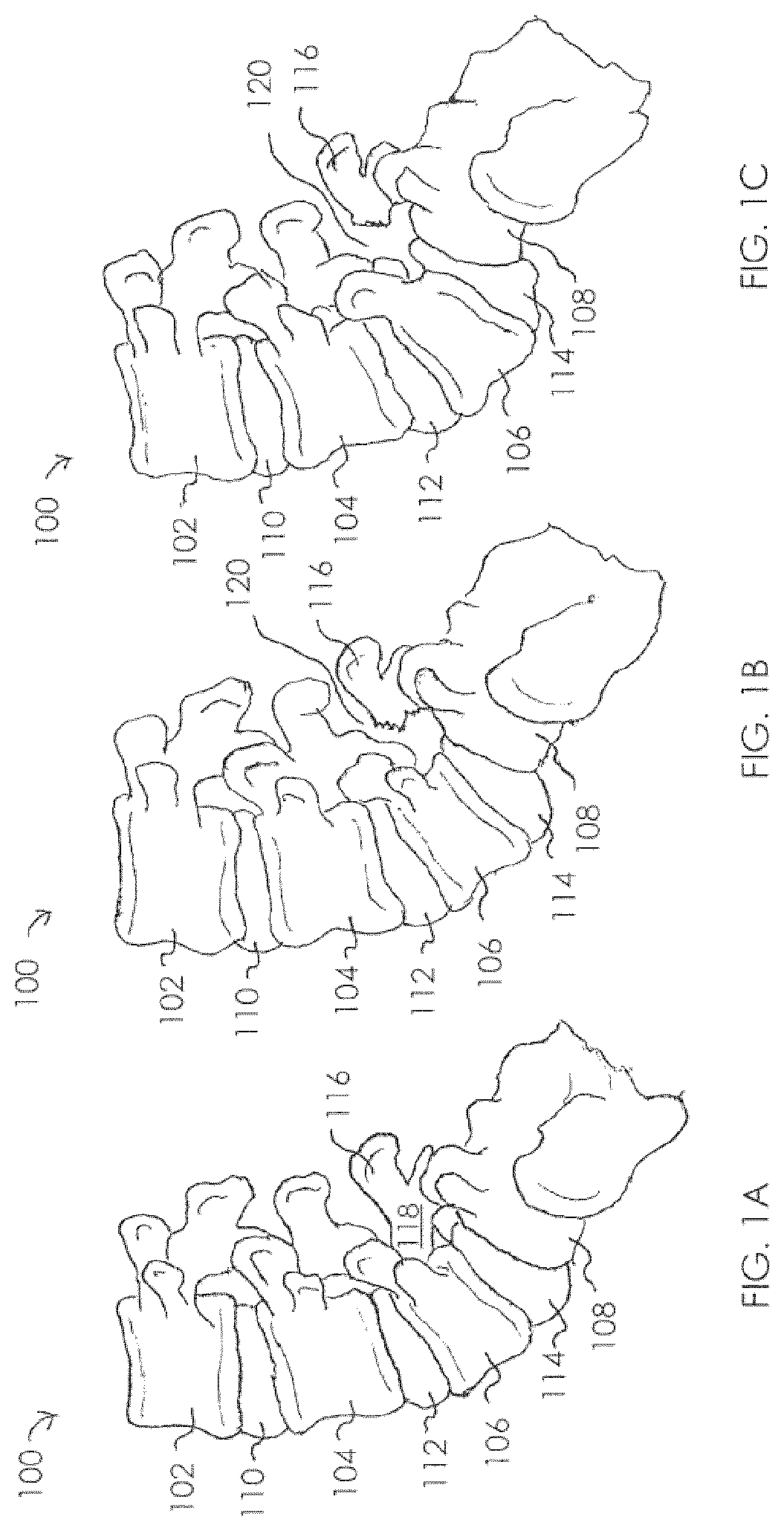
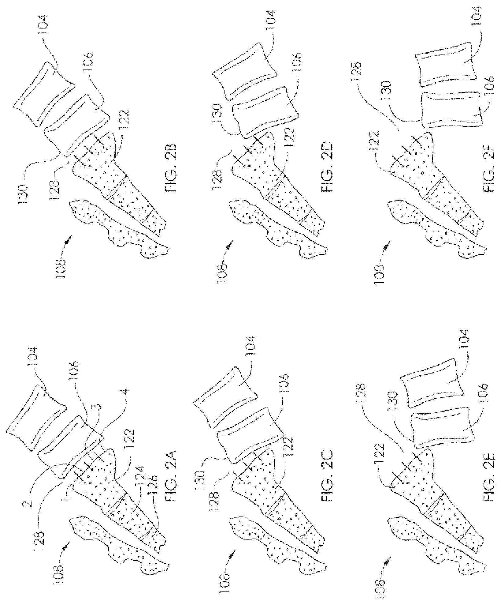
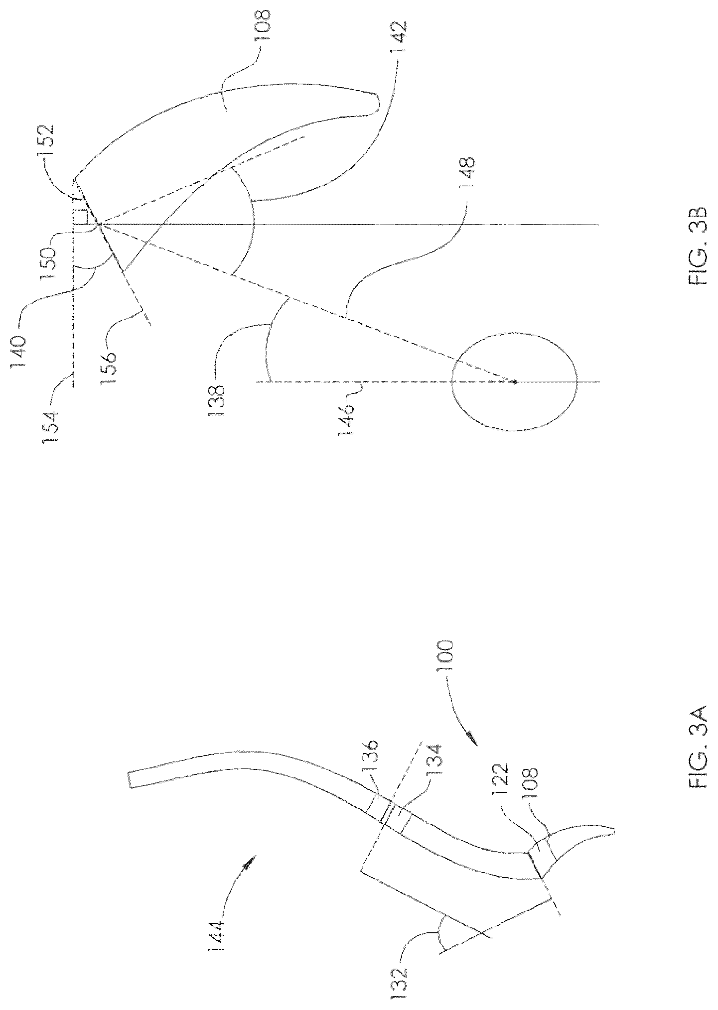
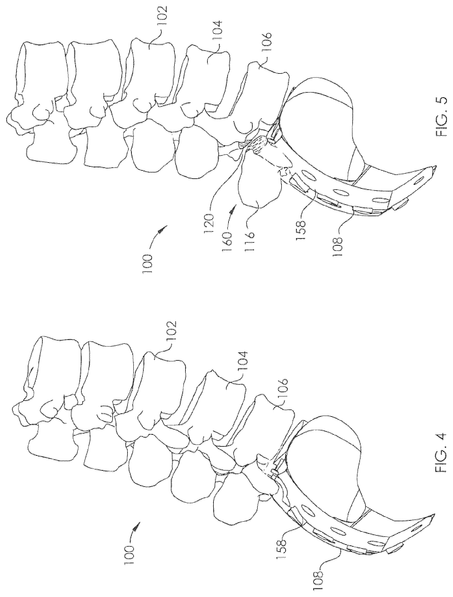
In one embodiment, a non-invasively adjustable spinal system for treatment of a subject having spondylolisthesis includes a first implantable actuator having at least one anchoring structure, the anchoring structure configured to facilitate securement of the first implantable actuator to a portion of the sacrum of the subject. The non-invasively adjustable spinal system can further include an adjustment element, configured to be coupled to the first implantable actuator, the adjustment element having an engagement structure configured to engage at least one transverse process of a lumbar vertebra of the subject. The non-invasively adjustable spinal system can further include a driving element, wherein remote activation of the driving element causes movement of the adjustment element in relation to the first implantable actuator.
| Inventors: | Green; Stuart A. (Long Beach, CA), Walker; Blair (Mission Viejo, CA), Buford; Thomas B. (Laguna Beach, CA), Weber; Urs (Irvine, CA) | ||||||||||
|---|---|---|---|---|---|---|---|---|---|---|---|
| Applicant: |
|
||||||||||
| Assignee: | NuVasive Specialized Orthopedics,
Inc. (San Diego, CA) |
||||||||||
| Family ID: | 52810302 | ||||||||||
| Appl. No.: | 14/511,084 | ||||||||||
| Filed: | October 9, 2014 |
Prior Publication Data
| Document Identifier | Publication Date | |
|---|---|---|
| US 20150105826 A1 | Apr 16, 2015 | |
Related U.S. Patent Documents
| Application Number | Filing Date | Patent Number | Issue Date | ||
|---|---|---|---|---|---|
| 61889496 | Oct 10, 2013 | ||||
| Current U.S. Class: | 1/1 |
| Current CPC Class: | A61B 17/7055 (20130101); A61B 17/7053 (20130101); A61B 17/707 (20130101); A61B 17/7016 (20130101) |
| Current International Class: | A61B 17/70 (20060101) |
References Cited [Referenced By]
U.S. Patent Documents
| 1599538 | September 1926 | Ludger |
| 3111945 | November 1963 | Von |
| 3372476 | March 1968 | Richard et al. |
| 3377576 | April 1968 | Edwin et al. |
| 3397928 | August 1968 | Galle |
| 3512901 | May 1970 | Law |
| 3527220 | September 1970 | Summers |
| 3597781 | August 1971 | Eibes et al. |
| 3726279 | April 1973 | Barefoot et al. |
| 3749098 | July 1973 | De Bennetot |
| 3750194 | August 1973 | Summers |
| 3810259 | May 1974 | Summers |
| 3840018 | October 1974 | Heifetz |
| 3866510 | February 1975 | Eibes et al. |
| 3900025 | August 1975 | Barnes, Jr. |
| 3915151 | October 1975 | Kraus |
| RE28907 | July 1976 | Eibes et al. |
| 3976060 | August 1976 | Hildebrandt et al. |
| 4010758 | March 1977 | Rockland et al. |
| 4056743 | November 1977 | Clifford et al. |
| 4068821 | January 1978 | Morrison |
| 4078559 | March 1978 | Nissinen |
| 4118805 | October 1978 | Reimels |
| 4204541 | May 1980 | Kapitanov |
| 4222374 | September 1980 | Sampson et al. |
| 4235246 | November 1980 | Weiss |
| 4256094 | March 1981 | Kapp et al. |
| 4286584 | September 1981 | Sampson et al. |
| 4300223 | November 1981 | Maire |
| 4357946 | November 1982 | Dutcher et al. |
| 4386603 | June 1983 | Mayfield |
| 4395259 | July 1983 | Prestele et al. |
| 4448191 | May 1984 | Rodnyansky et al. |
| 4486176 | December 1984 | Tardieu et al. |
| 4501266 | February 1985 | McDaniel |
| 4522501 | June 1985 | Shannon |
| 4537520 | August 1985 | Ochiai et al. |
| 4550279 | October 1985 | Klein |
| 4561798 | December 1985 | Elcrin et al. |
| 4573454 | March 1986 | Hoffman |
| 4592339 | June 1986 | Kuzmak et al. |
| 4592355 | June 1986 | Antebi |
| 4595007 | June 1986 | Mericle |
| 4642257 | February 1987 | Chase |
| 4658809 | April 1987 | Ulrich et al. |
| 4696288 | September 1987 | Kuzmak et al. |
| 4700091 | October 1987 | Wuthrich |
| 4747832 | May 1988 | Buffet |
| 4760837 | August 1988 | Petit |
| 4854304 | August 1989 | Zielke |
| 4872515 | October 1989 | Lundell |
| 4904861 | February 1990 | Epstein et al. |
| 4931055 | June 1990 | Bumpus et al. |
| 4940467 | July 1990 | Tronzo |
| 4957495 | September 1990 | Kluger |
| 4973331 | November 1990 | Pursley et al. |
| 4978323 | December 1990 | Freedman |
| 4998013 | March 1991 | Epstein et al. |
| 5010879 | April 1991 | Moriya et al. |
| 5030235 | July 1991 | Campbell, Jr. |
| 5041112 | August 1991 | Mingozzi et al. |
| 5053047 | October 1991 | Yoon |
| 5064004 | November 1991 | Lundell |
| 5074868 | December 1991 | Kuzmak |
| 5074882 | December 1991 | Grammont et al. |
| 5092889 | March 1992 | Campbell, Jr. |
| 5133716 | July 1992 | Plaza |
| 5142407 | August 1992 | Varaprasad et al. |
| 5152770 | October 1992 | Bengmark et al. |
| 5156605 | October 1992 | Pursley et al. |
| 5176618 | January 1993 | Freedman |
| 5180380 | January 1993 | Pursley et al. |
| 5222976 | June 1993 | Yoon |
| 5226429 | July 1993 | Kuzmak |
| 5261908 | November 1993 | Campbell, Jr. |
| 5263955 | November 1993 | Baumgart et al. |
| 5290289 | March 1994 | Sanders et al. |
| 5306275 | April 1994 | Bryan |
| 5330503 | July 1994 | Yoon |
| 5334202 | August 1994 | Carter |
| 5336223 | August 1994 | Rogers |
| 5356411 | October 1994 | Spievack |
| 5356424 | October 1994 | Buzerak et al. |
| 5360407 | November 1994 | Leonard et al. |
| 5364396 | November 1994 | Robinson et al. |
| 5381943 | January 1995 | Allen et al. |
| 5399168 | March 1995 | Wadsworth, Jr. et al. |
| 5403322 | April 1995 | Herzenberg et al. |
| 5429638 | July 1995 | Muschler et al. |
| 5433721 | July 1995 | Hooven et al. |
| 5437266 | August 1995 | McPherson et al. |
| 5449368 | September 1995 | Kuzmak |
| 5466261 | November 1995 | Richelsoph |
| 5468030 | November 1995 | Walling |
| 5480437 | January 1996 | Draenert |
| 5498262 | March 1996 | Bryan |
| 5509888 | April 1996 | Miller |
| 5516335 | May 1996 | Kummer et al. |
| 5527309 | June 1996 | Shelton |
| 5536269 | July 1996 | Spievack |
| 5536296 | July 1996 | Ten Eyck et al. |
| 5549610 | August 1996 | Russell et al. |
| 5573496 | November 1996 | McPherson et al. |
| 5575790 | November 1996 | Chen et al. |
| 5582616 | December 1996 | Bolduc et al. |
| 5601224 | February 1997 | Bishop et al. |
| 5620445 | April 1997 | Brosnahan et al. |
| 5620449 | April 1997 | Faccioli et al. |
| 5626579 | May 1997 | Muschler et al. |
| 5626613 | May 1997 | Schmieding |
| 5628888 | May 1997 | Bakhir et al. |
| 5632744 | May 1997 | Campbell, Jr. |
| 5659217 | August 1997 | Petersen |
| 5662683 | September 1997 | Kay |
| 5672175 | September 1997 | Martin |
| 5672177 | September 1997 | Seldin |
| 5676162 | October 1997 | Larson, Jr. et al. |
| 5693091 | December 1997 | Larson, Jr. et al. |
| 5700263 | December 1997 | Schendel |
| 5702430 | December 1997 | Larson, Jr. et al. |
| 5704893 | January 1998 | Timm |
| 5704938 | January 1998 | Staehlin et al. |
| 5704939 | January 1998 | Justin |
| 5720746 | February 1998 | Soubeiran |
| 5722429 | March 1998 | Larson, Jr. et al. |
| 5722930 | March 1998 | Larson, Jr. et al. |
| 5743910 | April 1998 | Bays et al. |
| 5758666 | June 1998 | Larson, Jr. et al. |
| 5762599 | June 1998 | Sohn |
| 5766208 | June 1998 | McEwan |
| 5771903 | June 1998 | Jakobsson |
| 5800434 | September 1998 | Campbell, Jr. |
| 5810815 | September 1998 | Morales |
| 5824008 | October 1998 | Bolduc et al. |
| 5827286 | October 1998 | Incavo et al. |
| 5829662 | November 1998 | Allen et al. |
| 5830221 | November 1998 | Stein et al. |
| 5843129 | December 1998 | Larson, Jr. et al. |
| 5874796 | February 1999 | Petersen |
| 5879375 | March 1999 | Larson, Jr. et al. |
| 5902304 | May 1999 | Walker et al. |
| 5935127 | August 1999 | Border |
| 5938669 | August 1999 | Klaiber et al. |
| 5945762 | August 1999 | Chen et al. |
| 5954915 | September 1999 | Voorhees et al. |
| 5961553 | October 1999 | Coty et al. |
| 5964763 | October 1999 | Incavo et al. |
| 5976138 | November 1999 | Baumgart et al. |
| 5979456 | November 1999 | Magovern |
| 5985110 | November 1999 | Bakhir et al. |
| 5997490 | December 1999 | McLeod et al. |
| 6009837 | January 2000 | McClasky |
| 6022349 | February 2000 | McLeod et al. |
| 6033412 | March 2000 | Losken et al. |
| 6034296 | March 2000 | Elvin et al. |
| 6067991 | May 2000 | Forsell |
| 6074341 | June 2000 | Anderson et al. |
| 6074882 | June 2000 | Eckardt |
| 6092531 | July 2000 | Chen et al. |
| 6102922 | August 2000 | Jakobsson et al. |
| 6106525 | August 2000 | Sachse |
| 6126660 | October 2000 | Dietz |
| 6126661 | October 2000 | Faccioli et al. |
| 6138681 | October 2000 | Chen et al. |
| 6139316 | October 2000 | Sachdeva et al. |
| 6162223 | December 2000 | Orsak et al. |
| 6183476 | February 2001 | Gerhardt et al. |
| 6200317 | March 2001 | Aalsma et al. |
| 6210347 | April 2001 | Forsell |
| 6217847 | April 2001 | Contag et al. |
| 6221074 | April 2001 | Cole et al. |
| 6234299 | May 2001 | Voorhees et al. |
| 6234956 | May 2001 | He et al. |
| 6241730 | June 2001 | Alby |
| 6245075 | June 2001 | Betz et al. |
| 6283156 | September 2001 | Motley |
| 6296643 | October 2001 | Hopf et al. |
| 6296656 | October 2001 | Bolduc et al. |
| 6299613 | October 2001 | Ogilvie et al. |
| 6315784 | November 2001 | Djurovic |
| 6319255 | November 2001 | Grundei et al. |
| 6321106 | November 2001 | Lemelson |
| 6325805 | December 2001 | Ogilvie et al. |
| 6327492 | December 2001 | Lemelson |
| 6331744 | December 2001 | Chen et al. |
| 6336929 | January 2002 | Justin |
| 6343568 | February 2002 | McClasky |
| 6358283 | March 2002 | Hogfors et al. |
| 6375682 | April 2002 | Fleischmann et al. |
| 6386083 | May 2002 | Hwang |
| 6389187 | May 2002 | Greenaway et al. |
| 6400980 | June 2002 | Lemelson |
| 6402753 | June 2002 | Cole et al. |
| 6409175 | June 2002 | Evans et al. |
| 6416516 | July 2002 | Stauch et al. |
| 6417750 | July 2002 | Sohn |
| 6423061 | July 2002 | Bryant |
| 6432040 | August 2002 | Meah |
| 6450173 | September 2002 | Forsell |
| 6450946 | September 2002 | Forsell |
| 6453907 | September 2002 | Forsell |
| 6454698 | September 2002 | Forsell |
| 6454699 | September 2002 | Forsell |
| 6454700 | September 2002 | Forsell |
| 6454701 | September 2002 | Forsell |
| 6460543 | October 2002 | Forsell |
| 6461292 | October 2002 | Forsell |
| 6461293 | October 2002 | Forsell |
| 6463935 | October 2002 | Forsell |
| 6464628 | October 2002 | Forsell |
| 6470892 | October 2002 | Forsell |
| 6471635 | October 2002 | Forsell |
| 6475136 | November 2002 | Forsell |
| 6482145 | November 2002 | Forsell |
| 6494879 | December 2002 | Lennox et al. |
| 6499907 | December 2002 | Baur |
| 6500110 | December 2002 | Davey et al. |
| 6503189 | January 2003 | Forsell |
| 6508820 | January 2003 | Bales |
| 6510345 | January 2003 | Van Bentem |
| 6511490 | January 2003 | Robert |
| 6527701 | March 2003 | Sayet et al. |
| 6527702 | March 2003 | Whalen et al. |
| 6536499 | March 2003 | Voorhees et al. |
| 6537196 | March 2003 | Creighton, IV et al. |
| 6547801 | April 2003 | Dargent et al. |
| 6554831 | April 2003 | Rivard et al. |
| 6558400 | May 2003 | Deem et al. |
| 6562051 | May 2003 | Bolduc et al. |
| 6565573 | May 2003 | Ferrante et al. |
| 6565576 | May 2003 | Stauch et al. |
| 6573706 | June 2003 | Mendes et al. |
| 6582313 | June 2003 | Perrow |
| 6583630 | June 2003 | Mendes et al. |
| 6587719 | July 2003 | Barrett et al. |
| 6595912 | July 2003 | Lau et al. |
| 6602184 | August 2003 | Lau et al. |
| 6604529 | August 2003 | Kim |
| 6607363 | August 2003 | Domroese |
| 6609025 | August 2003 | Barrett et al. |
| 6612978 | September 2003 | Lau et al. |
| 6612979 | September 2003 | Lau et al. |
| 6616669 | September 2003 | Ogilvie et al. |
| 6621956 | September 2003 | Greenaway et al. |
| 6626899 | September 2003 | Houser et al. |
| 6626917 | September 2003 | Craig |
| 6627206 | September 2003 | Lloyd |
| 6649143 | November 2003 | Contag et al. |
| 6656135 | December 2003 | Zogbi et al. |
| 6656194 | December 2003 | Gannoe et al. |
| 6657351 | December 2003 | Chen et al. |
| 6667725 | December 2003 | Simons et al. |
| 6669687 | December 2003 | Saadat |
| 6673079 | January 2004 | Kane |
| 6676674 | January 2004 | Dudai |
| 6682474 | January 2004 | Lau et al. |
| 6689046 | February 2004 | Sayet et al. |
| 6702732 | March 2004 | Lau et al. |
| 6702816 | March 2004 | Buhler |
| 6706042 | March 2004 | Taylor |
| 6709293 | March 2004 | Mori et al. |
| 6709385 | March 2004 | Forsell |
| 6730087 | May 2004 | Butsch |
| 6749556 | June 2004 | Banik |
| 6752754 | June 2004 | Feng et al. |
| 6761503 | July 2004 | Breese |
| 6765330 | July 2004 | Baur |
| 6769499 | August 2004 | Cargill et al. |
| 6773437 | August 2004 | Ogilvie et al. |
| 6774624 | August 2004 | Anderson et al. |
| 6789442 | September 2004 | Forch |
| 6796984 | September 2004 | Soubeiran |
| 6802844 | October 2004 | Ferree |
| 6802847 | October 2004 | Carson et al. |
| 6809434 | October 2004 | Duncan et al. |
| 6835183 | December 2004 | Lennox et al. |
| 6835207 | December 2004 | Zacouto et al. |
| 6849076 | February 2005 | Blunn et al. |
| 6852113 | February 2005 | Nathanson et al. |
| 6864647 | March 2005 | Duncan et al. |
| 6884248 | April 2005 | Bolduc et al. |
| 6890515 | May 2005 | Contag et al. |
| 6908605 | June 2005 | Contag et al. |
| 6915165 | July 2005 | Forsell |
| 6916462 | July 2005 | Contag et al. |
| 6918838 | July 2005 | Schwarzler et al. |
| 6918910 | July 2005 | Smith et al. |
| 6921360 | July 2005 | Banik |
| 6921400 | July 2005 | Sohngen |
| 6923951 | August 2005 | Contag et al. |
| 6926719 | August 2005 | Sohngen et al. |
| 6939533 | September 2005 | Contag et al. |
| 6953429 | October 2005 | Forsell |
| 6961553 | November 2005 | Zhao et al. |
| 6971143 | December 2005 | Domroese |
| 6980921 | December 2005 | Anderson et al. |
| 6997952 | February 2006 | Furukawa et al. |
| 7001327 | February 2006 | Whalen et al. |
| 7001346 | February 2006 | White |
| 7008425 | March 2006 | Phillips |
| 7011621 | March 2006 | Sayet et al. |
| 7011658 | March 2006 | Young |
| 7011682 | March 2006 | Lashinski et al. |
| 7018380 | March 2006 | Cole |
| 7029475 | April 2006 | Panjabi |
| 7041105 | May 2006 | Michelson |
| 7060075 | June 2006 | Govari et al. |
| 7060080 | June 2006 | Bachmann |
| 7063706 | June 2006 | Wittenstein |
| 7077802 | July 2006 | Lau et al. |
| 7081086 | July 2006 | Lau et al. |
| 7083629 | August 2006 | Weller et al. |
| 7096148 | August 2006 | Anderson et al. |
| 7097611 | August 2006 | Lau et al. |
| 7105029 | September 2006 | Doubler et al. |
| 7105968 | September 2006 | Nissen |
| 7114501 | October 2006 | Johnson et al. |
| 7115129 | October 2006 | Heggeness |
| 7115130 | October 2006 | Michelson |
| 7124493 | October 2006 | Lau et al. |
| 7128707 | October 2006 | Banik |
| 7135022 | November 2006 | Kosashvili et al. |
| 7160312 | January 2007 | Saadat |
| 7163538 | January 2007 | Altarac et al. |
| 7172607 | February 2007 | Hofle et al. |
| 7175589 | February 2007 | Deem et al. |
| 7175660 | February 2007 | Cartledge et al. |
| 7186262 | March 2007 | Saadat |
| 7188627 | March 2007 | Nelson et al. |
| 7189005 | March 2007 | Ward |
| 7189202 | March 2007 | Lau et al. |
| 7189251 | March 2007 | Kay |
| 7191007 | March 2007 | Desai et al. |
| 7194297 | March 2007 | Talpade et al. |
| 7195608 | March 2007 | Burnett |
| 7198774 | April 2007 | Contag et al. |
| 7211094 | May 2007 | Gannoe et al. |
| 7216648 | May 2007 | Nelson et al. |
| 7217284 | May 2007 | Houser et al. |
| 7218232 | May 2007 | DiSilvestro et al. |
| 7232449 | June 2007 | Sharkawy et al. |
| 7234468 | June 2007 | Johnson et al. |
| 7234544 | June 2007 | Kent |
| 7238152 | July 2007 | Lau et al. |
| 7238191 | July 2007 | Bachmann |
| 7241300 | July 2007 | Sharkawy et al. |
| 7243719 | July 2007 | Baron et al. |
| 7255682 | August 2007 | Bartol, Jr. et al. |
| 7255714 | August 2007 | Malek |
| 7255851 | August 2007 | Contag et al. |
| 7276022 | October 2007 | Lau et al. |
| 7282023 | October 2007 | Frering |
| 7285087 | October 2007 | Moaddeb et al. |
| 7288064 | October 2007 | Boustani et al. |
| 7288099 | October 2007 | Deem et al. |
| 7288101 | October 2007 | Deem et al. |
| 7296577 | November 2007 | Lashinski et al. |
| 7297150 | November 2007 | Cartledge et al. |
| 7299091 | November 2007 | Barrett et al. |
| 7302858 | December 2007 | Walsh et al. |
| 7306614 | December 2007 | Weller et al. |
| 7311690 | December 2007 | Burnett |
| 7314372 | January 2008 | Belfor et al. |
| 7314443 | January 2008 | Jordan et al. |
| 7320706 | January 2008 | Al-Najjar |
| 7331995 | February 2008 | Eisermann et al. |
| 7333013 | February 2008 | Berger |
| 7338433 | March 2008 | Coe |
| 7340306 | March 2008 | Barrett et al. |
| 7351198 | April 2008 | Byrum et al. |
| 7351240 | April 2008 | Hassler, Jr. et al. |
| 7353747 | April 2008 | Swayze et al. |
| 7357037 | April 2008 | Hnat et al. |
| 7357635 | April 2008 | Belfor et al. |
| 7360542 | April 2008 | Nelson et al. |
| 7361192 | April 2008 | Doty |
| 7364542 | April 2008 | Jambor et al. |
| 7364589 | April 2008 | Eisermann |
| 7367340 | May 2008 | Nelson et al. |
| 7367937 | May 2008 | Jambor et al. |
| 7367938 | May 2008 | Forsell |
| 7371244 | May 2008 | Chatlynne et al. |
| 7374557 | May 2008 | Conlon et al. |
| 7390007 | June 2008 | Helms et al. |
| 7390294 | June 2008 | Hassler, Jr. |
| 7400926 | July 2008 | Forsell |
| 7402134 | July 2008 | Moaddeb et al. |
| 7402176 | July 2008 | Malek |
| 7410461 | August 2008 | Lau et al. |
| 7416528 | August 2008 | Crawford et al. |
| 7422566 | September 2008 | Miethke |
| 7429259 | September 2008 | Cadeddu et al. |
| 7431692 | October 2008 | Zollinger et al. |
| 7441559 | October 2008 | Nelson et al. |
| 7442196 | October 2008 | Fisher et al. |
| 7445010 | November 2008 | Kugler et al. |
| 7455690 | November 2008 | Cartledge et al. |
| 7458981 | December 2008 | Fielding et al. |
| 7468060 | December 2008 | Utley et al. |
| 7476195 | January 2009 | Sayet et al. |
| 7476238 | January 2009 | Panjabi |
| 7481224 | January 2009 | Nelson et al. |
| 7481763 | January 2009 | Hassler, Jr. et al. |
| 7481841 | January 2009 | Hazebrouck et al. |
| 7485149 | February 2009 | White |
| 7489495 | February 2009 | Stevenson |
| 7494459 | February 2009 | Anstadt et al. |
| 7500484 | March 2009 | Nelson et al. |
| 7503922 | March 2009 | Deem et al. |
| 7503934 | March 2009 | Eisermann et al. |
| 7507252 | March 2009 | Lashinski et al. |
| 7510559 | March 2009 | Deem et al. |
| 7530981 | May 2009 | Kutsenko |
| 7531002 | May 2009 | Sutton et al. |
| 7547291 | June 2009 | Lennox et al. |
| 7553298 | June 2009 | Hunt et al. |
| 7559951 | July 2009 | DiSilvestro et al. |
| 7561916 | July 2009 | Hunt et al. |
| 7562660 | July 2009 | Saadat |
| 7566297 | July 2009 | Banik |
| 7569057 | August 2009 | Liu et al. |
| 7578821 | August 2009 | Fisher et al. |
| 7584788 | September 2009 | Baron et al. |
| 7594887 | September 2009 | Moaddeb et al. |
| 7601156 | October 2009 | Robinson |
| 7601162 | October 2009 | Hassler, Jr. et al. |
| 7601171 | October 2009 | Ainsworth et al. |
| 7611526 | November 2009 | Carl et al. |
| 7615001 | November 2009 | Jambor et al. |
| 7615068 | November 2009 | Timm et al. |
| 7618435 | November 2009 | Opolski |
| 7621886 | November 2009 | Burnett |
| 7635379 | December 2009 | Callahan et al. |
| 7651483 | January 2010 | Byrum et al. |
| 7658753 | February 2010 | Carl et al. |
| 7666132 | February 2010 | Forsell |
| 7666184 | February 2010 | Stauch |
| 7666210 | February 2010 | Franck et al. |
| 7678136 | March 2010 | Doubler et al. |
| 7678139 | March 2010 | Garamszegi et al. |
| 7691144 | April 2010 | Chang et al. |
| 7695512 | April 2010 | Lashinski et al. |
| 7704279 | April 2010 | Moskowitz et al. |
| 7704282 | April 2010 | Disilvestro et al. |
| 7708737 | May 2010 | Kraft et al. |
| 7708762 | May 2010 | McCarthy et al. |
| 7708765 | May 2010 | Carl et al. |
| 7708779 | May 2010 | Edie et al. |
| 7713287 | May 2010 | Timm et al. |
| 7717959 | May 2010 | William et al. |
| 7727141 | June 2010 | Hassler, Jr. et al. |
| 7727143 | June 2010 | Birk et al. |
| 7749224 | July 2010 | Cresina et al. |
| 7753913 | July 2010 | Szakelyhidi, Jr. et al. |
| 7753915 | July 2010 | Eksler et al. |
| 7757552 | July 2010 | Bogath et al. |
| 7762998 | July 2010 | Birk et al. |
| 7763053 | July 2010 | Gordon |
| 7763080 | July 2010 | Southworth |
| 7766815 | August 2010 | Ortiz |
| 7775099 | August 2010 | Bogath et al. |
| 7775215 | August 2010 | Hassler, Jr. et al. |
| 7776061 | August 2010 | Garner et al. |
| 7776068 | August 2010 | Ainsworth et al. |
| 7776075 | August 2010 | Bruneau et al. |
| 7776091 | August 2010 | Mastrorio et al. |
| 7780590 | August 2010 | Birk et al. |
| 7787958 | August 2010 | Stevenson |
| 7789912 | September 2010 | Manzi et al. |
| 7793583 | September 2010 | Radinger et al. |
| 7794447 | September 2010 | Dann et al. |
| 7794476 | September 2010 | Wisnewski |
| 7798954 | September 2010 | Birk et al. |
| 7799080 | September 2010 | Doty |
| 7803106 | September 2010 | Whalen et al. |
| 7803157 | September 2010 | Michelson |
| 7811275 | October 2010 | Birk et al. |
| 7811298 | October 2010 | Birk |
| 7811328 | October 2010 | Molz, IV et al. |
| 7815643 | October 2010 | Johnson et al. |
| 7828714 | November 2010 | Feng et al. |
| 7828813 | November 2010 | Mouton |
| 7833228 | November 2010 | Hershberger |
| 7835779 | November 2010 | Anderson et al. |
| 7837669 | November 2010 | Dann et al. |
| 7837691 | November 2010 | Cordes et al. |
| 7842036 | November 2010 | Phillips |
| 7845356 | December 2010 | Paraschac et al. |
| 7846188 | December 2010 | Moskowitz et al. |
| 7850660 | December 2010 | Uth et al. |
| 7850735 | December 2010 | Eisermann et al. |
| 7854769 | December 2010 | Hershberger |
| 7862546 | January 2011 | Conlon et al. |
| 7862574 | January 2011 | Deem et al. |
| 7862586 | January 2011 | Malek |
| 7867235 | January 2011 | Fell et al. |
| 7871368 | January 2011 | Zollinger et al. |
| 7875033 | January 2011 | Richter et al. |
| 7887566 | February 2011 | Hynes |
| 7901381 | March 2011 | Birk et al. |
| 7901419 | March 2011 | Bachmann et al. |
| 7909790 | March 2011 | Burnett |
| 7909838 | March 2011 | Deem et al. |
| 7909839 | March 2011 | Fields |
| 7909852 | March 2011 | Boomer et al. |
| 7918844 | April 2011 | Byrum et al. |
| 7921850 | April 2011 | Nelson et al. |
| 7922765 | April 2011 | Reiley |
| 7927354 | April 2011 | Edidin et al. |
| 7927357 | April 2011 | Sacher et al. |
| 7931679 | April 2011 | Heggeness |
| 7932825 | April 2011 | Berger |
| 7938836 | May 2011 | Ainsworth et al. |
| 7938841 | May 2011 | Sharkawy et al. |
| 7942903 | May 2011 | Moskowitz et al. |
| 7942908 | May 2011 | Sacher et al. |
| 7947011 | May 2011 | Birk et al. |
| 7951067 | May 2011 | Byrum et al. |
| 7951180 | May 2011 | Moskowitz et al. |
| 7958895 | June 2011 | Nelson et al. |
| 7958896 | June 2011 | Nelson et al. |
| 7959552 | June 2011 | Jordan et al. |
| 7972315 | July 2011 | Birk et al. |
| 7972346 | July 2011 | Bachmann et al. |
| 7972363 | July 2011 | Moskowitz et al. |
| 7976545 | July 2011 | Hershberger et al. |
| 7983763 | July 2011 | Stevenson et al. |
| 7985256 | July 2011 | Grotz et al. |
| 7987241 | July 2011 | St Jacques, Jr. et al. |
| 7988707 | August 2011 | Panjabi |
| 7988709 | August 2011 | Clark et al. |
| 7993342 | August 2011 | Malandain et al. |
| 7993397 | August 2011 | Lashinski et al. |
| 7998174 | August 2011 | Malandain et al. |
| 7998208 | August 2011 | Kohm et al. |
| 8002801 | August 2011 | Carl et al. |
| 8002809 | August 2011 | Baynham |
| 8007458 | August 2011 | Lennox et al. |
| 8007474 | August 2011 | Uth et al. |
| 8007479 | August 2011 | Birk et al. |
| 8011308 | September 2011 | Picchio |
| 8012162 | September 2011 | Bachmann |
| 8016745 | September 2011 | Hassler, Jr. et al. |
| 8016837 | September 2011 | Giger |
| 8016860 | September 2011 | Carl et al. |
| 8026729 | September 2011 | Kroh et al. |
| 8029477 | October 2011 | Byrum et al. |
| 8029567 | October 2011 | Edidin et al. |
| 8034080 | October 2011 | Malandain et al. |
| 8037871 | October 2011 | McClendon |
| 8038680 | October 2011 | Ainsworth et al. |
| 8038698 | October 2011 | Edidin et al. |
| 8043206 | October 2011 | Birk |
| 8043290 | October 2011 | Harrison et al. |
| 8043299 | October 2011 | Conway |
| 8043338 | October 2011 | Dant |
| 8043345 | October 2011 | Carl et al. |
| 8048169 | November 2011 | Burnett et al. |
| 8057473 | November 2011 | Orsak et al. |
| 8057513 | November 2011 | Kohm et al. |
| 8066650 | November 2011 | Lee et al. |
| 8070670 | December 2011 | Deem et al. |
| 8070671 | December 2011 | Deem et al. |
| 8070695 | December 2011 | Gupta et al. |
| 8070813 | December 2011 | Grotz et al. |
| 8074654 | December 2011 | Paraschac et al. |
| 8075577 | December 2011 | Deem et al. |
| 8079974 | December 2011 | Stergiopulos |
| 8079989 | December 2011 | Birk et al. |
| 8080022 | December 2011 | Deem et al. |
| 8080025 | December 2011 | Deem et al. |
| 8088166 | January 2012 | Makower et al. |
| 8092459 | January 2012 | Malandain |
| 8092499 | January 2012 | Roth |
| 8095317 | January 2012 | Ekseth et al. |
| 8096302 | January 2012 | Nelson et al. |
| 8096938 | January 2012 | Forsell |
| 8096995 | January 2012 | Kohm et al. |
| 8097018 | January 2012 | Malandain et al. |
| 8097038 | January 2012 | Malek |
| 8100819 | January 2012 | Banik |
| 8100943 | January 2012 | Malandain et al. |
| 8100967 | January 2012 | Makower et al. |
| 8105360 | January 2012 | Connor |
| 8105363 | January 2012 | Fielding et al. |
| 8105364 | January 2012 | McCarthy et al. |
| 8109974 | February 2012 | Boomer et al. |
| 8114158 | February 2012 | Carl et al. |
| 8123765 | February 2012 | Deem et al. |
| 8123805 | February 2012 | Makower et al. |
| 8128628 | March 2012 | Freid et al. |
| 8133280 | March 2012 | Voellmicke et al. |
| 8137349 | March 2012 | Soubeiran |
| 8137366 | March 2012 | Deem et al. |
| 8137367 | March 2012 | Deem et al. |
| 8142454 | March 2012 | Harrison et al. |
| 8142494 | March 2012 | Rahdert et al. |
| 8147517 | April 2012 | Trieu et al. |
| 8147549 | April 2012 | Metcalf, Jr. et al. |
| 8157841 | April 2012 | Malandain et al. |
| 8162897 | April 2012 | Byrum |
| 8162979 | April 2012 | Sachs et al. |
| 8163013 | April 2012 | Machold et al. |
| 8177789 | May 2012 | Magill et al. |
| 8182411 | May 2012 | Dlugos |
| 8187324 | May 2012 | Webler et al. |
| 8197544 | June 2012 | Manzi et al. |
| 8202305 | June 2012 | Reiley |
| 8211127 | July 2012 | Uth et al. |
| 8211149 | July 2012 | Justis |
| 8211151 | July 2012 | Schwab et al. |
| 8211179 | July 2012 | Molz, IV et al. |
| 8216275 | July 2012 | Fielding et al. |
| 8221420 | July 2012 | Keller |
| 8226690 | July 2012 | Altarac et al. |
| 8236002 | August 2012 | Fortin et al. |
| 8241292 | August 2012 | Collazo |
| 8241293 | August 2012 | Stone et al. |
| 8241331 | August 2012 | Arnin |
| 8246630 | August 2012 | Manzi et al. |
| 8251888 | August 2012 | Roslin et al. |
| 8252063 | August 2012 | Stauch |
| 8257370 | September 2012 | Moskowitz et al. |
| 8257442 | September 2012 | Edie et al. |
| 8263024 | September 2012 | Wan et al. |
| 8267969 | September 2012 | Altarac et al. |
| 8273112 | September 2012 | Garamszegi et al. |
| 8278941 | October 2012 | Kroh et al. |
| 8282671 | October 2012 | Connor |
| 8287540 | October 2012 | LeCronier et al. |
| 8298133 | October 2012 | Wiley et al. |
| 8298240 | October 2012 | Giger |
| 8308779 | November 2012 | Reiley |
| 8313423 | November 2012 | Forsell |
| 8316856 | November 2012 | Nelson et al. |
| 8317761 | November 2012 | Birk et al. |
| 8317802 | November 2012 | Manzi et al. |
| 8323290 | December 2012 | Metzger et al. |
| 8326435 | December 2012 | Stevenson |
| 8328807 | December 2012 | Brigido |
| 8328854 | December 2012 | Baynham et al. |
| 8333204 | December 2012 | Saadat |
| 8333790 | December 2012 | Timm et al. |
| 8353913 | January 2013 | Moskowitz et al. |
| 8357169 | January 2013 | Henniges et al. |
| 8357182 | January 2013 | Seme |
| 8357183 | January 2013 | Seme et al. |
| 8360955 | January 2013 | Sayet et al. |
| 8366628 | February 2013 | Denker et al. |
| 8372078 | February 2013 | Collazo |
| 8382652 | February 2013 | Sayet et al. |
| 8386018 | February 2013 | Stauch et al. |
| 8388667 | March 2013 | Reiley et al. |
| 8394124 | March 2013 | Biyani |
| 8394143 | March 2013 | Grotz et al. |
| 8403958 | March 2013 | Schwab |
| 8409203 | April 2013 | Birk et al. |
| 8409281 | April 2013 | Makower et al. |
| 8414584 | April 2013 | Brigido |
| 8414648 | April 2013 | Reiley |
| 8419755 | April 2013 | Deem et al. |
| 8419801 | April 2013 | DiSilvestro et al. |
| 8425570 | April 2013 | Reiley |
| 8425608 | April 2013 | Dewey et al. |
| 8433519 | April 2013 | Ekseth et al. |
| 8435268 | May 2013 | Thompson et al. |
| 8439915 | May 2013 | Harrison et al. |
| 8439926 | May 2013 | Bojarski et al. |
| 8444693 | May 2013 | Reiley |
| 8449553 | May 2013 | Kam et al. |
| 8449580 | May 2013 | Voellmicke et al. |
| 8454695 | June 2013 | Grotz et al. |
| 8469908 | June 2013 | Asfora |
| 8469978 | June 2013 | Fobi et al. |
| 8470003 | June 2013 | Voellmicke et al. |
| 8470004 | June 2013 | Reiley |
| 8475354 | July 2013 | Phillips et al. |
| 8475356 | July 2013 | Feng et al. |
| 8475499 | July 2013 | Cournoyer et al. |
| 8480554 | July 2013 | Phillips et al. |
| 8480668 | July 2013 | Fernandez et al. |
| 8480741 | July 2013 | Grotz et al. |
| 8486070 | July 2013 | Morgan et al. |
| 8486076 | July 2013 | Chavarria et al. |
| 8486110 | July 2013 | Fielding et al. |
| 8486113 | July 2013 | Malek |
| 8486147 | July 2013 | de Villiers et al. |
| 8491589 | July 2013 | Fisher et al. |
| 8494805 | July 2013 | Roche et al. |
| 8496662 | July 2013 | Novak et al. |
| 8500810 | August 2013 | Mastrorio et al. |
| 8506517 | August 2013 | Stergiopulos |
| 8506569 | August 2013 | Keefer et al. |
| 8517973 | August 2013 | Burnett |
| 8518062 | August 2013 | Cole et al. |
| 8518086 | August 2013 | Seme et al. |
| 8522790 | September 2013 | Nelson et al. |
| 8523865 | September 2013 | Reglos et al. |
| 8523866 | September 2013 | Sidebotham et al. |
| 8523883 | September 2013 | Saadat |
| 8529474 | September 2013 | Gupta et al. |
| 8529606 | September 2013 | Alamin et al. |
| 8529607 | September 2013 | Alamin et al. |
| 8529630 | September 2013 | Bojarski et al. |
| 8545384 | October 2013 | Forsell |
| 8545508 | October 2013 | Collazo |
| 8545814 | October 2013 | Contag et al. |
| 8551092 | October 2013 | Morgan et al. |
| 8551142 | October 2013 | Altarac et al. |
| 8551422 | October 2013 | Wan et al. |
| 8556901 | October 2013 | Anthony et al. |
| 8556911 | October 2013 | Mehta et al. |
| 8556975 | October 2013 | Ciupik et al. |
| 8562653 | October 2013 | Alamin et al. |
| 8568416 | October 2013 | Schmitz et al. |
| 8568457 | October 2013 | Hunziker |
| 8574267 | November 2013 | Linares |
| 8579919 | November 2013 | Bolduc et al. |
| 8579979 | November 2013 | Edie et al. |
| 8585595 | November 2013 | Heilman |
| 8585702 | November 2013 | Orsak et al. |
| 8585738 | November 2013 | Linares |
| 8585740 | November 2013 | Ross et al. |
| 8591549 | November 2013 | Lange |
| 8597362 | December 2013 | Shenoy et al. |
| 8613749 | December 2013 | Deem et al. |
| 8613758 | December 2013 | Linares |
| 8617212 | December 2013 | Linares |
| 8617220 | December 2013 | Skaggs |
| 8617243 | December 2013 | Eisermann et al. |
| 8622936 | January 2014 | Schenberger et al. |
| 8623036 | January 2014 | Harrison et al. |
| 8623042 | January 2014 | Roslin et al. |
| 8623056 | January 2014 | Linares |
| 8632544 | January 2014 | Haaja et al. |
| 8632547 | January 2014 | Maxson et al. |
| 8632548 | January 2014 | Soubeiran |
| 8632563 | January 2014 | Nagase et al. |
| 8632594 | January 2014 | Williams et al. |
| 8636770 | January 2014 | Hestad et al. |
| 8636771 | January 2014 | Butler et al. |
| 8636802 | January 2014 | Serhan et al. |
| 8641719 | February 2014 | Gephart et al. |
| 8641723 | February 2014 | Connor |
| 8652175 | February 2014 | Timm et al. |
| 8657765 | February 2014 | Asfora |
| 8657856 | February 2014 | Gephart et al. |
| 8657885 | February 2014 | Burnett et al. |
| 8663139 | March 2014 | Asfora |
| 8663140 | March 2014 | Asfora |
| 8663285 | March 2014 | Dall et al. |
| 8663287 | March 2014 | Butler et al. |
| 8663338 | March 2014 | Burnett et al. |
| 8668719 | March 2014 | Alamin et al. |
| 8673001 | March 2014 | Cartledge et al. |
| 8679161 | March 2014 | Malandain et al. |
| 8690858 | April 2014 | Machold et al. |
| 8707959 | April 2014 | Paraschac et al. |
| 8709090 | April 2014 | Makower et al. |
| 8715243 | May 2014 | Uth et al. |
| 8715290 | May 2014 | Fisher et al. |
| 8721570 | May 2014 | Gupta et al. |
| 8721643 | May 2014 | Morgan et al. |
| 8728125 | May 2014 | Bruneau et al. |
| 8734318 | May 2014 | Forsell |
| 8734516 | May 2014 | Moskowitz et al. |
| 8734519 | May 2014 | de Villiers et al. |
| 8747444 | June 2014 | Moskowitz et al. |
| 8752552 | June 2014 | Nelson et al. |
| 8758303 | June 2014 | Uth et al. |
| 8758347 | June 2014 | Weiner et al. |
| 8758355 | June 2014 | Fisher et al. |
| 8758372 | June 2014 | Cartledge et al. |
| 8762308 | June 2014 | Najarian et al. |
| 8764713 | July 2014 | Uth et al. |
| 8771272 | July 2014 | LeCronier et al. |
| 8777947 | July 2014 | Zahrly et al. |
| 8777995 | July 2014 | McClintock et al. |
| 8781744 | July 2014 | Ekseth et al. |
| 8784482 | July 2014 | Rahdert et al. |
| 8790343 | July 2014 | McClellan et al. |
| 8790380 | July 2014 | Buttermann |
| 8790409 | July 2014 | Van den Heuvel et al. |
| 8794243 | August 2014 | Deem et al. |
| 8795339 | August 2014 | Boomer et al. |
| 8801795 | August 2014 | Makower et al. |
| 8808206 | August 2014 | Asfora |
| 8813727 | August 2014 | McClendon |
| 8814869 | August 2014 | Freid et al. |
| 8828058 | September 2014 | Elsebaie et al. |
| 8828087 | September 2014 | Stone et al. |
| 8840623 | September 2014 | Reiley |
| 8840651 | September 2014 | Reiley |
| 8845692 | September 2014 | Wisnewski |
| 8845724 | September 2014 | Shenoy et al. |
| 8864717 | October 2014 | Conlon et al. |
| 8864823 | October 2014 | Cartledge et al. |
| 8870881 | October 2014 | Rezach et al. |
| 8870918 | October 2014 | Boomer et al. |
| 8870959 | October 2014 | Arnin |
| 8882699 | November 2014 | Burnett |
| 8882830 | November 2014 | Cartledge et al. |
| 8888672 | November 2014 | Phillips et al. |
| 8888673 | November 2014 | Phillips et al. |
| 8894663 | November 2014 | Giger et al. |
| 8915915 | December 2014 | Harrison et al. |
| 8915917 | December 2014 | Doherty et al. |
| 8920422 | December 2014 | Homeier et al. |
| 8932247 | January 2015 | Stergiopulos |
| 8945188 | February 2015 | Rezach et al. |
| 8945210 | February 2015 | Cartledge et al. |
| 8956407 | February 2015 | Macoviak et al. |
| 8961386 | February 2015 | Phillips et al. |
| 8961521 | February 2015 | Keefer et al. |
| 8961567 | February 2015 | Hunziker |
| 8968402 | March 2015 | Myers et al. |
| 8968406 | March 2015 | Arnin |
| 8986348 | March 2015 | Reiley |
| 8992527 | March 2015 | Guichet |
| 9005251 | April 2015 | Heggeness |
| 9005293 | April 2015 | Moskowitz et al. |
| 9005298 | April 2015 | Makower et al. |
| 9011491 | April 2015 | Carl et al. |
| 9015057 | April 2015 | Phillips et al. |
| 9022917 | May 2015 | Kasic et al. |
| 9028550 | May 2015 | Shulock et al. |
| 9033957 | May 2015 | Cadeddu et al. |
| 9033988 | May 2015 | Gephart et al. |
| 9034016 | May 2015 | Panjabi |
| 9044218 | June 2015 | Young |
| 9060810 | June 2015 | Kercher et al. |
| 9060844 | June 2015 | Kagan et al. |
| 9072530 | July 2015 | Mehta et al. |
| 9072606 | July 2015 | Lucas et al. |
| 9078703 | July 2015 | Arnin |
| 9084632 | July 2015 | Orsak et al. |
| 9089348 | July 2015 | Chavarria et al. |
| 9095436 | August 2015 | Boyden et al. |
| 9095437 | August 2015 | Boyden et al. |
| 9101422 | August 2015 | Freid et al. |
| 9101427 | August 2015 | Globerman et al. |
| 9107706 | August 2015 | Alamin et al. |
| 9113967 | August 2015 | Soubeiran |
| 9114016 | August 2015 | Shenoy et al. |
| 9125746 | September 2015 | Clifford et al. |
| 9138266 | September 2015 | Stauch |
| 9144482 | September 2015 | Sayet |
| 9155565 | October 2015 | Boomer et al. |
| 9161856 | October 2015 | Nelson et al. |
| 9168071 | October 2015 | Seme et al. |
| 9168076 | October 2015 | Patty et al. |
| 9173681 | November 2015 | Seme |
| 9173715 | November 2015 | Baumgartner |
| 9186158 | November 2015 | Anthony et al. |
| 9186185 | November 2015 | Hestad et al. |
| 9198771 | December 2015 | Ciupik |
| 9204899 | December 2015 | Buttermann |
| 9204908 | December 2015 | Buttermann |
| 9220536 | December 2015 | Skaggs |
| 9226783 | January 2016 | Brigido |
| 9242070 | January 2016 | Tieu |
| 9259243 | February 2016 | Giger et al. |
| 9272159 | March 2016 | Phillips et al. |
| 9278004 | March 2016 | Shenoy et al. |
| 9278046 | March 2016 | Asfora |
| 9282997 | March 2016 | Hunziker |
| 9301792 | April 2016 | Henniges et al. |
| 9301854 | April 2016 | Moskowitz et al. |
| 9308089 | April 2016 | Vicatos et al. |
| 9308387 | April 2016 | Phillips et al. |
| 9320618 | April 2016 | Schmitz et al. |
| 9326728 | May 2016 | Demir et al. |
| 9333009 | May 2016 | Kroll et al. |
| 9339197 | May 2016 | Griswold et al. |
| 9339300 | May 2016 | Kantelhardt |
| 9339307 | May 2016 | McClintock et al. |
| 9339312 | May 2016 | Doherty et al. |
| 9358044 | June 2016 | Seme et al. |
| 9364267 | June 2016 | Northcutt et al. |
| 9370388 | June 2016 | Globerman et al. |
| 9393123 | July 2016 | Lucas et al. |
| 9408644 | August 2016 | Zahrly et al. |
| 9421347 | August 2016 | Burnett |
| 9427267 | August 2016 | Homeier et al. |
| 9439744 | September 2016 | Forsell |
| 9439797 | September 2016 | Baym et al. |
| 9445848 | September 2016 | Anderson et al. |
| 9451997 | September 2016 | Carl et al. |
| 9456953 | October 2016 | Asfora |
| 9474612 | October 2016 | Haaja et al. |
| 9492199 | November 2016 | Orsak et al. |
| 9492276 | November 2016 | Lee et al. |
| 9498258 | November 2016 | Boomer et al. |
| 9498366 | November 2016 | Burnett et al. |
| 9510834 | December 2016 | Burnett et al. |
| 9532804 | January 2017 | Clifford et al. |
| 9561062 | February 2017 | Hayes et al. |
| 9561063 | February 2017 | Reiley |
| 9572588 | February 2017 | Fisher et al. |
| 9572746 | February 2017 | Asfora |
| 9572910 | February 2017 | Messersmith et al. |
| 9579110 | February 2017 | Bojarski et al. |
| 9579203 | February 2017 | Soubeiran |
| 9603605 | March 2017 | Collazo |
| 9603713 | March 2017 | Moskowitz et al. |
| 9610161 | April 2017 | Macoviak et al. |
| 9622875 | April 2017 | Moskowitz et al. |
| 9642735 | May 2017 | Burnett |
| 9655651 | May 2017 | Panjabi |
| 9668868 | June 2017 | Shenoy et al. |
| 9687243 | June 2017 | Burnett et al. |
| 9687414 | June 2017 | Asfora |
| 9693867 | July 2017 | Lucas et al. |
| 9700419 | July 2017 | Clifford et al. |
| 9700450 | July 2017 | Burnett |
| 9717537 | August 2017 | Gordon |
| 9724135 | August 2017 | Koch et al. |
| 9724265 | August 2017 | Asfora |
| 9730738 | August 2017 | Gephart et al. |
| 9743969 | August 2017 | Reiley |
| 9782206 | October 2017 | Mueckter et al. |
| 9795410 | October 2017 | Shenoy et al. |
| 9814600 | November 2017 | Shulock et al. |
| 9820789 | November 2017 | Reiley |
| 9826987 | November 2017 | Keefer et al. |
| 9833291 | December 2017 | Baumgartner |
| 9848894 | December 2017 | Burley et al. |
| 9848993 | December 2017 | Moskowitz et al. |
| 9861376 | January 2018 | Chavarria et al. |
| 9861390 | January 2018 | Hunziker |
| 9861404 | January 2018 | Reiley |
| 9867719 | January 2018 | Moskowitz et al. |
| 2001/0011543 | August 2001 | Forsell |
| 2002/0019580 | February 2002 | Lau et al. |
| 2002/0050112 | May 2002 | Koch et al. |
| 2002/0072758 | June 2002 | Reo et al. |
| 2002/0164905 | November 2002 | Bryant |
| 2003/0019498 | January 2003 | Forsell |
| 2003/0040671 | February 2003 | Somogyi et al. |
| 2003/0066536 | April 2003 | Forsell |
| 2003/0109881 | June 2003 | Shirado |
| 2003/0114731 | June 2003 | Cadeddu et al. |
| 2003/0187447 | October 2003 | Ferrante et al. |
| 2003/0208212 | November 2003 | Cigaina |
| 2003/0220643 | November 2003 | Ferree |
| 2003/0220644 | November 2003 | Thelen et al. |
| 2004/0006342 | January 2004 | Altarac et al. |
| 2004/0011137 | January 2004 | Hnat et al. |
| 2004/0011365 | January 2004 | Govari et al. |
| 2004/0019353 | January 2004 | Freid et al. |
| 2004/0023623 | February 2004 | Stauch et al. |
| 2004/0055610 | March 2004 | Forsell |
| 2004/0064030 | April 2004 | Forsell |
| 2004/0068205 | April 2004 | Zogbi et al. |
| 2004/0092939 | May 2004 | Freid et al. |
| 2004/0098121 | May 2004 | Opolski |
| 2004/0116773 | June 2004 | Furness et al. |
| 2004/0133219 | July 2004 | Forsell |
| 2004/0138725 | July 2004 | Forsell |
| 2004/0153106 | August 2004 | Dudai |
| 2004/0158254 | August 2004 | Eisermann |
| 2004/0172040 | September 2004 | Heggeness |
| 2004/0173222 | September 2004 | Kim |
| 2004/0193266 | September 2004 | Meyer |
| 2004/0220567 | November 2004 | Eisermann et al. |
| 2004/0220668 | November 2004 | Eisermann et al. |
| 2004/0230307 | November 2004 | Eisermann |
| 2004/0250820 | December 2004 | Forsell |
| 2004/0260287 | December 2004 | Ferree |
| 2004/0260319 | December 2004 | Egle |
| 2005/0002984 | January 2005 | Byrum et al. |
| 2005/0043802 | February 2005 | Eisermann et al. |
| 2005/0055025 | March 2005 | Zacouto et al. |
| 2005/0070937 | March 2005 | Jambor et al. |
| 2005/0080427 | April 2005 | Govari et al. |
| 2005/0080439 | April 2005 | Carson et al. |
| 2005/0090823 | April 2005 | Bartimus |
| 2005/0096750 | May 2005 | Kagan et al. |
| 2005/0131352 | June 2005 | Conlon et al. |
| 2005/0159754 | July 2005 | Odrich |
| 2005/0159755 | July 2005 | Odrich |
| 2005/0165440 | July 2005 | Cancel et al. |
| 2005/0171543 | August 2005 | Timm et al. |
| 2005/0177164 | August 2005 | Walters et al. |
| 2005/0182400 | August 2005 | White |
| 2005/0182401 | August 2005 | Timm et al. |
| 2005/0182412 | August 2005 | Johnson et al. |
| 2005/0192629 | September 2005 | Saadat et al. |
| 2005/0222489 | October 2005 | Rahdert et al. |
| 2005/0234289 | October 2005 | Anstadt et al. |
| 2005/0234448 | October 2005 | McCarthy |
| 2005/0234462 | October 2005 | Hershberger |
| 2005/0246034 | November 2005 | Soubeiran |
| 2005/0251109 | November 2005 | Soubeiran |
| 2005/0261779 | November 2005 | Meyer |
| 2005/0272976 | December 2005 | Tanaka et al. |
| 2005/0288672 | December 2005 | Ferree |
| 2006/0020278 | January 2006 | Burnett et al. |
| 2006/0036246 | February 2006 | Carl et al. |
| 2006/0036251 | February 2006 | Reiley |
| 2006/0036259 | February 2006 | Carl et al. |
| 2006/0036323 | February 2006 | Carl et al. |
| 2006/0036324 | February 2006 | Sachs et al. |
| 2006/0047282 | March 2006 | Gordon |
| 2006/0058790 | March 2006 | Carl et al. |
| 2006/0058792 | March 2006 | Hynes |
| 2006/0079897 | April 2006 | Harrison et al. |
| 2006/0116757 | June 2006 | Lashinski et al. |
| 2006/0124140 | June 2006 | Forsell |
| 2006/0136062 | June 2006 | DiNello et al. |
| 2006/0142634 | June 2006 | Anstadt et al. |
| 2006/0142767 | June 2006 | Green et al. |
| 2006/0155279 | July 2006 | Ogilvie |
| 2006/0155347 | July 2006 | Forsell |
| 2006/0184240 | August 2006 | Jimenez et al. |
| 2006/0184248 | August 2006 | Edidin et al. |
| 2006/0195088 | August 2006 | Sacher et al. |
| 2006/0195102 | August 2006 | Malandain |
| 2006/0204156 | September 2006 | Takehara et al. |
| 2006/0211909 | September 2006 | Anstadt et al. |
| 2006/0235299 | October 2006 | Martinelli |
| 2006/0235424 | October 2006 | Vitale |
| 2006/0241746 | October 2006 | Shaoulian et al. |
| 2006/0249914 | November 2006 | Dulin |
| 2006/0252983 | November 2006 | Lembo et al. |
| 2006/0271107 | November 2006 | Harrison et al. |
| 2006/0276812 | December 2006 | Hill et al. |
| 2006/0282073 | December 2006 | Simanovsky |
| 2006/0289014 | December 2006 | Purdy et al. |
| 2006/0293671 | December 2006 | Heggeness |
| 2006/0293683 | December 2006 | Stauch |
| 2007/0010814 | January 2007 | Stauch |
| 2007/0015955 | January 2007 | Tsonton |
| 2007/0021644 | January 2007 | Woolson et al. |
| 2007/0031131 | February 2007 | Griffitts |
| 2007/0043376 | February 2007 | Leatherbury et al. |
| 2007/0050030 | March 2007 | Kim |
| 2007/0055237 | March 2007 | Edidin et al. |
| 2007/0055368 | March 2007 | Rhee et al. |
| 2007/0118215 | May 2007 | Moaddeb |
| 2007/0135913 | June 2007 | Moaddeb et al. |
| 2007/0161993 | July 2007 | Lowery |
| 2007/0162032 | July 2007 | Johnson et al. |
| 2007/0173837 | July 2007 | Chan et al. |
| 2007/0173869 | July 2007 | Gannoe et al. |
| 2007/0179493 | August 2007 | Kim |
| 2007/0213751 | September 2007 | Scirica et al. |
| 2007/0239159 | October 2007 | Altarac et al. |
| 2007/0250084 | October 2007 | Sharkawy et al. |
| 2007/0255088 | November 2007 | Jacobson et al. |
| 2007/0256693 | November 2007 | Paraschac et al. |
| 2007/0260270 | November 2007 | Assell et al. |
| 2007/0264605 | November 2007 | Belfor et al. |
| 2007/0270631 | November 2007 | Nelson et al. |
| 2007/0276369 | November 2007 | Allard et al. |
| 2007/0276372 | November 2007 | Malandain et al. |
| 2007/0276373 | November 2007 | Malandain |
| 2007/0276493 | November 2007 | Malandain et al. |
| 2007/0288024 | December 2007 | Gollogly |
| 2007/0288183 | December 2007 | Bulkes et al. |
| 2008/0015577 | January 2008 | Loeb |
| 2008/0021454 | January 2008 | Chao et al. |
| 2008/0021455 | January 2008 | Chao et al. |
| 2008/0021456 | January 2008 | Gupta et al. |
| 2008/0033431 | February 2008 | Jung et al. |
| 2008/0033436 | February 2008 | Song et al. |
| 2008/0051784 | February 2008 | Gollogly |
| 2008/0051788 | February 2008 | Schwab |
| 2008/0051895 | February 2008 | Malandain et al. |
| 2008/0058936 | March 2008 | Malandain et al. |
| 2008/0058937 | March 2008 | Malandain et al. |
| 2008/0065077 | March 2008 | Ferree |
| 2008/0065215 | March 2008 | Reiley |
| 2008/0066764 | March 2008 | Paraschac et al. |
| 2008/0071275 | March 2008 | Ferree |
| 2008/0071276 | March 2008 | Ferree |
| 2008/0082118 | April 2008 | Edidin et al. |
| 2008/0082167 | April 2008 | Edidin et al. |
| 2008/0083413 | April 2008 | Forsell |
| 2008/0086128 | April 2008 | Lewis |
| 2008/0091059 | April 2008 | Machold et al. |
| 2008/0097487 | April 2008 | Pool et al. |
| 2008/0097523 | April 2008 | Bolduc et al. |
| 2008/0108995 | May 2008 | Conway et al. |
| 2008/0140188 | June 2008 | Rahdert et al. |
| 2008/0140200 | June 2008 | Heinz |
| 2008/0147139 | June 2008 | Barrett et al. |
| 2008/0147192 | June 2008 | Edidin et al. |
| 2008/0161933 | July 2008 | Grotz et al. |
| 2008/0167685 | July 2008 | Allard et al. |
| 2008/0172063 | July 2008 | Taylor |
| 2008/0177319 | July 2008 | Schwab |
| 2008/0177326 | July 2008 | Thompson |
| 2008/0195156 | August 2008 | Ainsworth et al. |
| 2008/0226563 | September 2008 | Contag et al. |
| 2008/0228186 | September 2008 | Gall et al. |
| 2008/0255615 | October 2008 | Vittur et al. |
| 2008/0272928 | November 2008 | Shuster |
| 2008/0275552 | November 2008 | Makower et al. |
| 2008/0275555 | November 2008 | Makower et al. |
| 2008/0275557 | November 2008 | Makower et al. |
| 2008/0275567 | November 2008 | Makower et al. |
| 2008/0293995 | November 2008 | Moaddeb et al. |
| 2009/0012565 | January 2009 | Sachs |
| 2009/0076597 | March 2009 | Dahlgren et al. |
| 2009/0082815 | March 2009 | Zylber et al. |
| 2009/0088766 | April 2009 | Magill et al. |
| 2009/0088803 | April 2009 | Justis et al. |
| 2009/0093820 | April 2009 | Trieu et al. |
| 2009/0093890 | April 2009 | Gelbart |
| 2009/0112207 | April 2009 | Walker et al. |
| 2009/0118699 | May 2009 | Utley et al. |
| 2009/0125062 | May 2009 | Arnin |
| 2009/0171356 | July 2009 | Klett |
| 2009/0177203 | July 2009 | Reiley |
| 2009/0182356 | July 2009 | Coe |
| 2009/0192514 | July 2009 | Feinberg et al. |
| 2009/0198144 | August 2009 | Phillips et al. |
| 2009/0204055 | August 2009 | Lennox et al. |
| 2009/0216113 | August 2009 | Meier et al. |
| 2009/0216262 | August 2009 | Burnett et al. |
| 2009/0240173 | September 2009 | Hsia et al. |
| 2009/0259236 | October 2009 | Burnett et al. |
| 2009/0270871 | October 2009 | Liu et al. |
| 2009/0275984 | November 2009 | Kim et al. |
| 2009/0306717 | December 2009 | Kercher |
| 2009/0318919 | December 2009 | Robinson |
| 2010/0004654 | January 2010 | Schmitz et al. |
| 2010/0030281 | February 2010 | Gollogly |
| 2010/0057127 | March 2010 | McGuire et al. |
| 2010/0081868 | April 2010 | Moaddeb et al. |
| 2010/0094302 | April 2010 | Pool et al. |
| 2010/0094303 | April 2010 | Chang |
| 2010/0100185 | April 2010 | Trieu et al. |
| 2010/0106192 | April 2010 | Barry |
| 2010/0106193 | April 2010 | Barry |
| 2010/0114103 | May 2010 | Harrison et al. |
| 2010/0121323 | May 2010 | Pool |
| 2010/0121457 | May 2010 | Clifford et al. |
| 2010/0130941 | May 2010 | Conlon et al. |
| 2010/0137872 | June 2010 | Kam et al. |
| 2010/0137911 | June 2010 | Dant |
| 2010/0137913 | June 2010 | Khatchadourian |
| 2010/0145449 | June 2010 | Makower et al. |
| 2010/0145462 | June 2010 | Ainsworth et al. |
| 2010/0168751 | July 2010 | Anderson et al. |
| 2010/0179601 | July 2010 | Jung et al. |
| 2010/0198261 | August 2010 | Trieu et al. |
| 2010/0228167 | September 2010 | Ilovich et al. |
| 2010/0241168 | September 2010 | Franck et al. |
| 2010/0249782 | September 2010 | Durham |
| 2010/0249839 | September 2010 | Alamin et al. |
| 2010/0249847 | September 2010 | Jung et al. |
| 2010/0256626 | October 2010 | Muller et al. |
| 2010/0256684 | October 2010 | Seme et al. |
| 2010/0262160 | October 2010 | Boyden et al. |
| 2010/0262239 | October 2010 | Boyden et al. |
| 2010/0262247 | October 2010 | Arnin |
| 2010/0274290 | October 2010 | Jung et al. |
| 2010/0280551 | November 2010 | Pool et al. |
| 2010/0286730 | November 2010 | Gordon |
| 2010/0286791 | November 2010 | Goldsmith |
| 2010/0318129 | December 2010 | Seme et al. |
| 2010/0324600 | December 2010 | Biyani |
| 2010/0324684 | December 2010 | Eisermann et al. |
| 2010/0331883 | December 2010 | Schmitz et al. |
| 2011/0004076 | January 2011 | Janna et al. |
| 2011/0054536 | March 2011 | Elsebaie et al. |
| 2011/0057756 | March 2011 | Marinescu et al. |
| 2011/0060422 | March 2011 | Makower et al. |
| 2011/0066188 | March 2011 | Seme et al. |
| 2011/0077738 | March 2011 | Cuipik et al. |
| 2011/0098748 | April 2011 | Jangra |
| 2011/0098819 | April 2011 | Eisermann et al. |
| 2011/0106165 | May 2011 | Schwab et al. |
| 2011/0118790 | May 2011 | Reilly |
| 2011/0130702 | June 2011 | Stergiopulos |
| 2011/0184505 | July 2011 | Sharkawy et al. |
| 2011/0196371 | August 2011 | Forsell |
| 2011/0196435 | August 2011 | Forsell |
| 2011/0202138 | August 2011 | Shenoy et al. |
| 2011/0238126 | September 2011 | Soubeiran |
| 2011/0257655 | October 2011 | Copf, Jr. |
| 2011/0275879 | November 2011 | Nelson et al. |
| 2011/0284014 | November 2011 | Cadeddu et al. |
| 2012/0019341 | January 2012 | Gabay et al. |
| 2012/0019342 | January 2012 | Gabay et al. |
| 2012/0053633 | March 2012 | Stauch |
| 2012/0088953 | April 2012 | King |
| 2012/0089186 | April 2012 | Carl et al. |
| 2012/0089191 | April 2012 | Altarac et al. |
| 2012/0109207 | May 2012 | Trieu |
| 2012/0116522 | May 2012 | Makower et al. |
| 2012/0116535 | May 2012 | Ratron et al. |
| 2012/0130426 | May 2012 | Thompson |
| 2012/0136390 | May 2012 | Butler et al. |
| 2012/0136449 | May 2012 | Makower et al. |
| 2012/0150231 | June 2012 | Alamin |
| 2012/0172883 | July 2012 | Sayago |
| 2012/0179273 | July 2012 | Clifford et al. |
| 2012/0185040 | July 2012 | Rahdert et al. |
| 2012/0203282 | August 2012 | Sachs et al. |
| 2012/0221101 | August 2012 | Moaddeb et al. |
| 2012/0259364 | October 2012 | Lange |
| 2012/0271353 | October 2012 | Barry |
| 2012/0277747 | November 2012 | Keller |
| 2012/0283781 | November 2012 | Arnin |
| 2012/0296234 | November 2012 | Wilhelm et al. |
| 2012/0296430 | November 2012 | Edie et al. |
| 2012/0312307 | December 2012 | Paraschac et al. |
| 2013/0013066 | January 2013 | Landry et al. |
| 2013/0018468 | January 2013 | Moskowitz et al. |
| 2013/0018469 | January 2013 | Moskowitz et al. |
| 2013/0023991 | January 2013 | Moskowitz et al. |
| 2013/0079830 | March 2013 | Garamszegi et al. |
| 2013/0138017 | May 2013 | Jundt et al. |
| 2013/0138154 | May 2013 | Reiley |
| 2013/0150889 | June 2013 | Fening et al. |
| 2013/0172940 | July 2013 | Skaggs |
| 2013/0178903 | July 2013 | Abdou |
| 2013/0197639 | August 2013 | Clifford et al. |
| 2013/0204266 | August 2013 | Heilman |
| 2013/0204376 | August 2013 | DiSilvestro et al. |
| 2013/0238094 | September 2013 | Voellmicke et al. |
| 2013/0245692 | September 2013 | Hayes et al. |
| 2013/0253344 | September 2013 | Griswold et al. |
| 2013/0253587 | September 2013 | Carls et al. |
| 2013/0261623 | October 2013 | Voellmicke et al. |
| 2013/0261672 | October 2013 | Horvath |
| 2013/0268005 | October 2013 | Rezach et al. |
| 2013/0268011 | October 2013 | Rezach et al. |
| 2013/0296863 | November 2013 | Globerman et al. |
| 2013/0296940 | November 2013 | Northcutt et al. |
| 2013/0325006 | December 2013 | Michelinie et al. |
| 2013/0325071 | December 2013 | Niemiec et al. |
| 2013/0331889 | December 2013 | Alamin et al. |
| 2013/0345802 | December 2013 | Cartledge et al. |
| 2014/0005788 | January 2014 | Haaja et al. |
| 2014/0018913 | January 2014 | Cartledge et al. |
| 2014/0025172 | January 2014 | Lucas et al. |
| 2014/0031826 | January 2014 | Bojarski et al. |
| 2014/0031929 | January 2014 | Cartledge et al. |
| 2014/0039558 | February 2014 | Alamin et al. |
| 2014/0051914 | February 2014 | Fobi et al. |
| 2014/0052134 | February 2014 | Orisek |
| 2014/0058392 | February 2014 | Mueckter et al. |
| 2014/0058450 | February 2014 | Arlet |
| 2014/0066987 | March 2014 | Hestad et al. |
| 2014/0067075 | March 2014 | Makower et al. |
| 2014/0080203 | March 2014 | Wan et al. |
| 2014/0088715 | March 2014 | Ciupik |
| 2014/0107704 | April 2014 | Serhan et al. |
| 2014/0114311 | April 2014 | Pool et al. |
| 2014/0128920 | May 2014 | Kantelhardt |
| 2014/0135838 | May 2014 | Alamin et al. |
| 2014/0142631 | May 2014 | Hunziker |
| 2014/0142698 | May 2014 | Landry et al. |
| 2014/0163664 | June 2014 | Goldsmith |
| 2014/0172097 | June 2014 | Clifford et al. |
| 2014/0194932 | July 2014 | Bruneau et al. |
| 2014/0222138 | August 2014 | Machold et al. |
| 2014/0236234 | August 2014 | Kroll et al. |
| 2014/0296918 | October 2014 | Fening et al. |
| 2014/0303538 | October 2014 | Baym et al. |
| 2014/0303539 | October 2014 | Baym et al. |
| 2014/0303540 | October 2014 | Baym et al. |
| 2014/0324047 | October 2014 | Zahrly et al. |
| 2014/0336756 | November 2014 | Lee et al. |
| 2014/0358150 | December 2014 | Kaufman et al. |
| 2015/0013687 | January 2015 | Paraschac et al. |
| 2015/0057490 | February 2015 | Forsell |
| 2015/0073565 | March 2015 | Nelson et al. |
| 2015/0105782 | April 2015 | D'Lima et al. |
| 2015/0105824 | April 2015 | Moskowitz et al. |
| 2015/0132174 | May 2015 | Marinescu et al. |
| 2015/0134007 | May 2015 | Alamin et al. |
| 2015/0142110 | May 2015 | Myers et al. |
| 2015/0150561 | June 2015 | Burnett et al. |
| 2015/0272600 | October 2015 | Mehta et al. |
| 2015/0313649 | November 2015 | Alamin et al. |
| 20068468 | Mar 2001 | AU | |||
| 101040807 | Sep 2007 | CN | |||
| 1541262 | Jun 1969 | DE | |||
| 8515687 | Dec 1985 | DE | |||
| 68515687.6 | Dec 1985 | DE | |||
| 19626230 | Jan 1998 | DE | |||
| 19751733 | Dec 1998 | DE | |||
| 19745654 | Apr 1999 | DE | |||
| 102005045070 | Apr 2007 | DE | |||
| 102007053362 | May 2009 | DE | |||
| 0663184 | Jul 1995 | EP | |||
| 1547549 | Jun 2005 | EP | |||
| 1745765 | Jan 2007 | EP | |||
| 1905388 | Apr 2008 | EP | |||
| 2802406 | Jun 2001 | FR | |||
| 2823663 | Oct 2002 | FR | |||
| 2827756 | Jan 2003 | FR | |||
| 2892617 | May 2007 | FR | |||
| 2900563 | Nov 2007 | FR | |||
| 2901991 | Dec 2007 | FR | |||
| 2916622 | Dec 2008 | FR | |||
| 2961386 | Dec 2011 | FR | |||
| 1174814 | Dec 1969 | GB | |||
| 223454 | Apr 2002 | HU | |||
| 05-104022 | Apr 1993 | JP | |||
| 09-056736 | Mar 1997 | JP | |||
| 2001-507608 | Jun 2001 | JP | |||
| 2003-172372 | Jun 2003 | JP | |||
| 2003-530195 | Oct 2003 | JP | |||
| 2007-050339 | Mar 2007 | JP | |||
| WO8604498 | Aug 1986 | WO | |||
| WO8707134 | Dec 1987 | WO | |||
| WO8906940 | Aug 1989 | WO | |||
| WO9601597 | Jan 1996 | WO | |||
| WO9808454 | Mar 1998 | WO | |||
| WO9830163 | Jul 1998 | WO | |||
| WO/1998/044858 | Oct 1998 | WO | |||
| WO1998044858 | Oct 1998 | WO | |||
| WO9850309 | Nov 1998 | WO | |||
| WO9903348 | Jan 1999 | WO | |||
| WO9923744 | May 1999 | WO | |||
| WO9951160 | Oct 1999 | WO | |||
| WO1999051160 | Oct 1999 | WO | |||
| WO9963907 | Dec 1999 | WO | |||
| WO0000108 | Jan 2000 | WO | |||
| WO0072768 | Dec 2000 | WO | |||
| WO0105463 | Jan 2001 | WO | |||
| WO0112108 | Feb 2001 | WO | |||
| WO0124742 | Apr 2001 | WO | |||
| WO2001024697 | Apr 2001 | WO | |||
| WO0141671 | Jun 2001 | WO | |||
| WO0145485 | Jun 2001 | WO | |||
| WO0145487 | Jun 2001 | WO | |||
| WO0145597 | Jun 2001 | WO | |||
| WO0158390 | Aug 2001 | WO | |||
| WO0167973 | Sep 2001 | WO | |||
| WO0178614 | Oct 2001 | WO | |||
| WO0236975 | May 2002 | WO | |||
| WO03059215 | Jul 2003 | WO | |||
| WO2004014245 | Feb 2004 | WO | |||
| WO2004019796 | Mar 2004 | WO | |||
| WO2004021870 | Mar 2004 | WO | |||
| WO2004043280 | May 2004 | WO | |||
| WO2005023090 | Mar 2005 | WO | |||
| WO2005072195 | Aug 2005 | WO | |||
| WO2005072664 | Aug 2005 | WO | |||
| WO2005105001 | Nov 2005 | WO | |||
| WO2006019520 | Feb 2006 | WO | |||
| WO2006019521 | Feb 2006 | WO | |||
| WO2006089085 | Aug 2006 | WO | |||
| WO2006090380 | Aug 2006 | WO | |||
| WO2006103071 | Oct 2006 | WO | |||
| WO2006103074 | Oct 2006 | WO | |||
| WO2006105084 | Oct 2006 | WO | |||
| WO2007013059 | Feb 2007 | WO | |||
| WO2007015239 | Feb 2007 | WO | |||
| WO2007025191 | Mar 2007 | WO | |||
| WO/2007/048012 | Apr 2007 | WO | |||
| WO2007048012 | Apr 2007 | WO | |||
| WO2007081304 | Jul 2007 | WO | |||
| WO2007118179 | Oct 2007 | WO | |||
| WO2007140180 | Dec 2007 | WO | |||
| WO2007149555 | Dec 2007 | WO | |||
| WO20071144489 | Dec 2007 | WO | |||
| WO2008003952 | Jan 2008 | WO | |||
| WO2008013623 | Jan 2008 | WO | |||
| WO2008015679 | Feb 2008 | WO | |||
| WO2008040880 | Apr 2008 | WO | |||
| WO2008140756 | Nov 2008 | WO | |||
| WO2010017649 | Feb 2010 | WO | |||
| WO2010050891 | May 2010 | WO | |||
| WO2010056650 | May 2010 | WO | |||
| WO2011018778 | Feb 2011 | WO | |||
| WO2011116158 | Sep 2011 | WO | |||
| WO/2013/066946 | May 2013 | WO | |||
| WO2013119528 | Aug 2013 | WO | |||
| WO2013181329 | Dec 2013 | WO | |||
| WO2014040013 | Mar 2014 | WO | |||
| WO2011041398 | Apr 2015 | WO | |||
Other References
|
US 9,161,784 B2, 10/2015, Buttermann (withdrawn) cited by applicant . Kasliwal, M., Smith, J., Kanter, A., Chen, C-J., Mummaneni, P., Hart, R., Shaffrey, C. "Management of High-Grade Spondylolisthesis," Neurosrugery Clinics of North America, 2013, vol. 24, pp. 275-291, W.B. Saunders, Philadelphia, United States. cited by applicant . Abe, Jun, Kensei Nagata, Mamoru Ariyoshi, and Akio Inoue. "Experimental external fixation combined with percutaneous discectomy in the management of scoliosis." Spine 24, No. 7 (1999): 646-653. cited by applicant . Amer, A. R. A. L., and Ashraf A. Khanfour. "Evaluation of treatment of late-onset tibia vara using gradual angulationtranslation high tibial osteotomy." Acta orthopaedica Belgica 76, No. 3 (2010): 360. cited by applicant . Angrisani, L., F. Favretti, F. Furbetta, S. Gennai, G. Segato, V. Borrelli, A. Sergio, T. Lafullarde, G. Vander Velpen, and M Lorenzo. "Lap-Band ((R)) Rapid Port (TM) System: Preliminary results in 21 patients." In Obesity Surgery, vol. 15, No. 7,pp. 936-936. cited by applicant . Baumgart, Rainer, Stefan Hinterwimmer, Michael Krammer, Oliver Muensterer, and Wolf Mutschler. "The bioexpandable prosthesis: a new perspective after resection of malignant bone tumors in children." Journal of pediatric hematology/oncology 27, No. 8 (2005): 452-455. cited by applicant . Baumgart, R., P. Thaller, S. Hinterwimmer, M. Krammer, T. Hierl, and W. Mutschler. "A fully implantable, programmable distraction nail (Fitbone)--new perspectives for corrective and reconstructive limb surgery." In Practice of Intramedullary Locked Nails, pp. 189-198. Springer Berlin Heidelberg, 2006. cited by applicant . Bodo, Laszlo, Laszlo Hangody, Balazs Borsitzky, Gyorgy Beres, Gabriella Arato, Peter Nagy, and Gabor K. Rathonyi. "Development of a tension-adjustable implant for anterior cruciate ligament reconstruction." Eklem Hast Cerrahisi 19, No. 1 (2008): 27-32. cited by applicant . Boudjemline, Younes, Emmanuelle Pineau, Caroline Bonnet, Alix Mollet, Sylvia Abadir, Damien Bonnet, Daniel Sidi, and Gabriella Agnoletti. "Off-label use of an adjustable gastric banding system for pulmonary artery banding." The Journal of thoracic and cardiovascular surgery 131, No. 5 (2006): 1130-1135. cited by applicant . Brochure--VEPTR II Technique Guide 4/08. cited by applicant . Brochure--VEPTR Patient Guide dated Feb. 2005. cited by applicant . Brown, S. "Single Port Surgery and the Dundee Endocone." SAGES Annual Scientific Sessions, Poster Abstracts (2007): 323-324. cited by applicant . Buchowski, Jacob M., Rishi Bhatnagar, David L. Skaggs, and Paul D. Sponseller. "Temporary internal distraction as an aid to correction of severe scoliosis." The Journal of Bone & Joint Surgery 88, No. 9 (2006): 2035-2041. cited by applicant . Burghardt, R. D., J. E. Herzenberg, S. C. Specht, and D. Paley. "Mechanical failure of the Intramedullary Skeletal Kinetic Distractor in limb lengthening." Journal of Bone & Joint Surgery, British vol. 93, No. 5 (2011): 639-643. cited by applicant . Burke, John Gerard. "Design of a minimally invasive non fusion device for the surgical management of scoliosis in the skeletally immature." Studies in health technology and informatics 123 (2005): 378-384. cited by applicant . Carter, D. R., and W. E. Caler. "A cumulative damage model for bone fracture." Journal of Orthopaedic Research 3, No. 1 (1985): 84-90. cited by applicant . Chapman, Andrew E., George Kiroff, Philip Game, Bruce Foster, Paul O'Brien, John Ham, and Guy J. Maddern. "Laparoscopic adjustable gastric banding in the treatment of obesity: a systematic literature review." Surgery 135, No. 3 (2004): 326-351. cited by applicant . Cole, J. Dean, Daniel Justin, Tagus Kasparis, Derk DeVlught, and Carl Knobloch. "The intramedullary skeletal distractor (ISKD): first clinical results of a new intramedullary nail for lengthening of the femur and tibia." Injury 32 (2001):129-139. cited by applicant . Cole, J., D. Paley, and M. Dahl. "Operative Technique. ISKD. Intramedullary Skeletal Kinetic Distractor. Tibial Surgical Technique." IS-0508 (A)-OPT-US .COPYRGT. Orthofix Inc 28 (2005). cited by applicant . Dailey, Hannah L., Charles J. Daly, John G. Galbraith, Michael Cronin, and James A. Harty. "A novel intramedullary nail for micromotion stimulation of tibial fractures." Clinical Biomechanics 27, No. 2 (2012): 182-188. cited by applicant . Daniels, A. U., Patrick Gemperline, Allen R. Grahn, and Harold K. Dunn. "A new method for continuous intraoperative measurement of Harrington rod loading patterns." Annals of biomedical engineering 12, No. 3 (1984): 233-246. cited by applicant . De Giorgi, G., G. Stella, S. Becchetti, G. Martucci, and D. Miscioscia. "Cotrel-Dubousset instrumentation for the treatment of severe scoliosis." European Spine Journal 8, No. 1 (1999): 8-15. cited by applicant . Dorsey, W. O., Bruce S. Miller, Jared P. Tadje, and Cari R. Bryant. "The stability of three commercially available implants used in medial opening wedge high tibial osteotomy." The journal of knee surgery 19, No. 2 (2006): 95-98. cited by applicant . Edeland, H. G., G. Eriksson, and E. Dahlberg. "Instrumentation for distraction by limited surgery in scoliosis treatment." Journal of biomedical engineering 3, No. 2 (1981): 143-146. cited by applicant . Ember, T., and H. Noordeen. "Distraction forces required during growth rod lengthening." Journal of Bone & Joint Surgery, British vol. 88, No. SUPP II (2006): 229-229. cited by applicant . Fabry, Hans, Robrecht Van Hee, Leo Hendrickx, and Eric Totte. "A technique for prevention of port adjustable silicone gastric banding." Obesity surgery 12, No. 2 (2002): 285-288. cited by applicant . Fried, M., W. Lechner, and K. Kormanova. "In vivo measurements of different gastric band pressures towards the gastric wall at the stoma region." In Obesity Surgery, vol. 14, No. 7, pp. 914-914. 3100 Bayview Ave, Unit 4, Toronto, Ontario M2N 5L3, Canada: F D-Communications Inc, 2004. cited by applicant . Gao, Xiaochong, Derek Gordon, Dongping Zhang, Richard Browne, Cynthia Helms, Joseph Gillum, Samuel Weber et al. "CHD7 gene polymorphisms are associated with susceptibility to idiopathic scoliosis." The American Journal of Human Genetics 80, No. 5 (2007): 957-965. cited by applicant . Gebhart, M., M. Neel, A. Soubeiran, and J. Dubousset. "Early clinical experience with a custom made growing endoprosthesis in children with malignant bone tumors of the lower extremity actioned by an external permanent magnet: the Phenix M system." In International Society of Limb Salvage 14th International Symposium on Limb Salvage.2007. cited by applicant . Gillespie, R., and J. Obrien. "Harrington instrumentation without fusion." In Journal of Bone and Joint Surgerybritish Volume, vol. 63, No. 3, pp. 461-461. 22 Buckingham Street, London, England WC2N 6ET: British Editorial Soc Bone Joint Surgery, 1981. cited by applicant . Goodship, Allen E., James L. Cunningham, and John Kenwright. "Strain rate and timing of stimulation in mechanical modulation of fracture healing." Clinical orthopaedics and related research 355 (1998): S105-S115. cited by applicant . Grass, P. Jose, A. Valentin Soto, and H. Paula Araya. "Intermittent distracting rod for correction of high neurologic risk congenital scoliosis." Spine 22, No. 16 (1997): 1922-1927. cited by applicant . Gray's Anatomy, http://education.yahoo.com/reference/gray/subjects/subject/128, published Jul. 1, 2007. cited by applicant . Grimer, R., S. Carter, R. Tillman, A. Abudu, and L. Jeys. "Non-Invasive Extendable Endoprostheses for Children--Expensive But Worth It!." Journal of Bone & Joint Surgery, British vol. 93, No. SUPP I (2011): 5-5. cited by applicant . Grunert, R. D. "[The development of a totally implantable electronic sphincter]." Langenbecks Archiv fur Chirurgie 325 (1968): 1170-1174. cited by applicant . Guichet, Jean-Marc, Barbara Deromedis, Leo T. Donnan, Giovanni Peretti, Pierre Lascombes, and Flavio Bado. "Gradual femoral lengthening with the Albizzia intramedullary nail." The Journal of Bone & Joint Surgery 85, No. 5 (2003): 838-848. cited by applicant . Gupta, A., J. Meswania, R. Pollock, S. R. Cannon, T. W. R. Briggs, S. Taylor, and G. Blunn. "Non-invasive distal femoral expandable endoprosthesis for limb-salvage surgery in paediatric tumours." Journal of Bone & Joint Surgery, British vol. 88, No. 5 (2006): 649-654. cited by applicant . Hankemeier S, Gosling T, Pape HC, et al. Limb lengthening with the Intramedullary Skeletal Kinetic Distractor (ISKD) Oper Orthop Traumatol. 2005;17:79-101. cited by applicant . Harrington PR (1962) Treatment of scoliosis. Correction and internal fixation by spine instrumentation. J Bone Joint Surg Am 44-A:591-610. cited by applicant . Hazem Elsebaie, M. D. "Single Growing Rods." Changing the Foundations: Does it affect the Results., J Child Orthop. (2007) 1:258. cited by applicant . Hennig, Alex C.; Incavo, Stephen J.; Beynnon, Bruce D.; Abate, Joseph A.; Urse, John S.; Kelly, Stephen / The safety and efficacy of a new adjustable plate used for proximal tibial opening wedge osteotomy in the treatment of unicompartmental knee osteoarthrosis. In: The journal of knee surgery, vol. 20, No. 1, Jan. 1, 2007, p. 6-14. cited by applicant . Hofmeister, M., C. Hierholzer, and V. Buhren. "Callus Distraction with the Albizzia Nail." In Practice of Intramedullary Locked Nails, pp. 211-215. Springer Berlin Heidelberg, 2006. cited by applicant . Horbach, T., D. Herzog, and I. Knerr. "First experiences with the routine use of the Rapid Port (TM) system with the Lap-Band (R)." In Obesity Surgery, vol. 16, No. 4, pp. 418-418. 3100 Bayview Ave, Unit 4, Toronto, Ontario M2N 5L3, Canada: F D-Communications Inc, 2006. cited by applicant . Hyodo, Akira, Helmuth Kotschi, Helen Kambic, and George Muschler. "Bone transport using intramedullary fixation and a single flexible traction cable." Clinical orthopaedics and related research 325 (1996): 256-268. cited by applicant . Ahlbom, A., U. Bergqvist, J. H. Bernhardt, J. P. Cesarini, M. Grandolfo, M. Hietanen, A. F. Mckinlay et al. "Guidelines for limiting exposure to time-varying electric, magnetic, and electromagnetic fields (up to 300 GHz). International Commission on Non-Ionizing Radiation Protection." Health Phys 74, No. 4 (1998): 494-522. cited by applicant . International Commission on Non-Ionizing Radiation Protection. "Guidelines on limits of exposure to static magnetic fields." Health Physics 96, No. 4 (2009): 504-514. cited by applicant . INVIS.RTM./Lamello Catalog, 2006, Article No. 68906A001 GB. cited by applicant . Kasliwal, Manish K., Justin S. Smith, Adam Kanter, Ching-Jen Chen, Praveen V. Mummaneni, Robert A. Hart, and Christopher I. Shaffrey. "Management of high-grade spondylolisthesis." Neurosurgery Clinics of North America 24, No. 2 (2013): 275-291. cited by applicant . Kenawey, Mohamed, Christian Krettek, Emmanouil Liodakis, Ulrich Wiebking, and Stefan Hankemeier. "Leg lengthening using intramedullay skeletal kinetic distractor: results of 57 consecutive applications." Injury 42, No. 2 (2011): 150-155. cited by applicant . Kent, Matthew E., Arvind Arora, P. Julian Owen, and Vikas Khanduja. "Assessment and correction of femoral malrotation following intramedullary nailing of the femur." Acta Orthop Belg 76, No. 5 (2010): 580-4. cited by applicant . Klemme, William R., Francis Denis, Robert B. Winter, John W. Lonstein, and Steven E. Koop. "Spinal instrumentation without fusion for progressive scoliosis in young children." Journal of Pediatric Orthopaedics 17, No. 6 (1997): 734-742. cited by applicant . Korenkov, M., S. Sauerland, N. Yucel, L. Kohler, P. Goh, J. Schierholz, and H. Troidl. "Port function after laparoscopic adjustable gastric banding for morbid obesity." Surgical Endoscopy and Other Interventional Techniques 17, No. 7 (2003): 1068-1071. cited by applicant . Krieg, Andreas H., Bernhard M. Speth, and Bruce K. Foster. "Leg lengthening with a motorized nail in adolescents." Clinical orthopaedics and related research 466, No. 1 (2008): 189-197. cited by applicant . Kucukkaya, Metin, Raffi Armagan, and Unal Kuzgun. "The new intramedullary cable bone transport technique." Journal of orthopaedic trauma 23, No. 7 (2009): 531-536. cited by applicant . Lechner, W. L., W. Kirchmayr, and G. Schwab. "In vivo band manometry: a new method in band adjustment." In Obesity Surgery, vol. 15, No. 7, pp. 935-935. 3100 Bayview Ave, Unit 4, Toronto, Ontario M2N 5L3, Canada: F Dcommunicationsinc, 2005. cited by applicant . Lechner, W., M. Gadenstatter, R. Ciovica, W. Kirchmayer, and G. Schwab. "Intra-band manometry for band adjustments: The basics." In Obesity Surgery, vol. 16, No. 4, pp. 417-418. 3100 Bayview Ave, Unit 4, Toronto, Ontario M2N 5L3, Canada: F D-Communications Inc, 2006. cited by applicant . Li, G., S. Berven, N. A. Athanasou, and A. H. R. W. Simpson. "Bone transport over an intramedullary nail: A case report with histologic examination of the regenerated segment." Injury 30, No. 8 (1999): 525-534. cited by applicant . Lonner, Baron S. "Emerging minimally invasive technologies for the management of scoliosis." Orthopedic Clinics of North America 38, No. 3 (2007): 431-440. cited by applicant . Teli, Marco MD. "Measurement of Forces Generated During Distraction of Growing Rods, J." Marco Teli. Journal of Child Orthop 1 (2007): 257-258. cited by applicant . Matthews, Michael Wayne, Harry Conrad Eggleston, Steven D. Pekarek, and Greg Eugene Hilmas. "Magnetically adjustable intraocular lens." Journal of Cataract & Refractive Surgery 29, No. 11 (2003): 2211-2216. cited by applicant . Micromotion "Micro Drive Engineering General catalogue" pp. 14 24; Jun. 2009. cited by applicant . Mineiro, Jorge, and Stuart L. Weinstein. "Subcutaneous rodding for progressive spinal curvatures: early results." Journal of Pediatric Orthopaedics 22, No. 3 (2002): 290-295. cited by applicant . Moe, John H., Khalil Kharrat, Robert B. Winter, and John L. Cummine. "Harrington instrumentation without fusion plus external orthotic support for the treatment of difficult curvature problems in young children." Clinical orthopaedics and related research 185 (1984): 35-45. cited by applicant . Montague, R. G., C. M. Bingham, and K. Atallah. "Magnetic gear dynamics for servo control." In MELECON 2010-2010 15th IEEE Mediterranean Electrotechnical Conference, pp. 1192-1197. IEEE, 2010. cited by applicant . Montague, Ryan, Chris Bingham, and Kais Atallah. "Servo control of magnetic gears." Mechatronics, IEEE/ASME Transactions on 17, No. 2 (2012): 269-278. cited by applicant . Nachemson, Alf, and Gosta Elfstrom. "Intravital wireless telemetry of axial forces in Harrington distraction rods in patients with idiopathic scoliosis." The Journal of Bone & Joint Surgery 53, No. 3 (1971): 445-465. cited by applicant . Nachlas, I. William, and Jesse N. Borden. "The cure of experimental scoliosis by directed growth control." The Journal of Bone & Joint Surgery 33, No. 1 (1951): 24-34. cited by applicant . Newton, P. "Fusionless Scoliosis Correction by Anterolateral Tethering . . . Can it Work?." In 39th Annual Scoliosis Research Society Meeting. 2004. cited by applicant . Observations by a third party under Article 115 EPC issued by the European Patent Office dated Feb. 15, 2010 in European Patent Application No. 08805612.2, Applicant: Soubeiran, Arnaud (7 pages). cited by applicant . Oh, Chang-Wug, Hae-Ryong Song, Jae-Young Roh, Jong-Keon Oh, Woo-Kie Min, Hee-Soo Kyung, Joon-Woo Kim, Poong-Taek Kim, and Joo-Chul Ihn. "Bone transport over an intramedullary nail for reconstruction of long bone defects in tibia." Archives of orthopaedic and trauma surgery 128, No. 8 (2008): 801-808. cited by applicant . Ozcivici, Engin, Yen Kim Luu, Ben Adler, Yi-Xian Qin, Janet Rubin, Stefan Judex, and Clinton T. Rubin. "Mechanical signals as anabolic agents in bone." Nature Reviews Rheumatology 6, No. 1 (2010): 50-59. cited by applicant . Patient Guide, VEPTR Vertical Expandable Prosthetic Titanium Rib, Synthes Spine (2005) (23pages). cited by applicant . Piorkowski, James R., Scott J. Ellner, Arun A. Mavanur, and Carlos A. Barba. "Preventing port site inversion in laparoscopic adjustable gastric banding." Surgery for Obesity and Related Diseases 3, No. 2 (2007): 159-161. cited by applicant . Prontes, Isabel, http://wwwehow.com/about_4795793_longest-bone-body.html, published Jun. 12, 2012. cited by applicant . Rathjen, Karl, Megan Wood, Anna McClung, and Zachary Vest. "Clinical and radiographic results after implant removal in idiopathic scoliosis." Spine 32, No. 20 (2007): 2184-2188. cited by applicant . Ren, Christine J., and George A. Fielding. "Laparoscopic adjustable gastric banding: surgical technique." Journal of Laparoendoscopic & Advanced Surgical Techniques 13, No. 4 (2003): 257-263. cited by applicant . Reyes-Sanchez, Alejandro, Luis Miguel Rosales, and Victor Miramontes. "External fixation for dynamic correction of severe scoliosis." The Spine Journal 5, No. 4 (2005): 418-426. cited by applicant . Rinsky, Lawrence A., James G. Gamble, and Eugene E. Bleck. "Segmental Instrumentation Without Fusion in Children With Progressive Scoliosis." Journal of Pediatric Orthopedics 5, No. 6 (1985): 687-690. cited by applicant . Rode, V., F. Gay, A. J. Baraza, and J. Dargent. "A simple way to adjust bands under radiologic control." In Obesity Surgery, vol. 16, No. 4, pp. 418-418. 3100 Bayview Ave, Unit 4, Toronto, Ontario M2N 5L3, Canada: F DCommunications Inc, 2006. cited by applicant . Schmerling, M. A., M. A. Wilkov, A. E. Sanders, and J. E. Woosley. "Using the shape recovery of nitinol in the Harrington rod treatment of scoliosis." Journal of biomedical materials research 10, No. 6 (1976): 879-892. cited by applicant . Scott, D. J., S. J. Tang, R. Fernandez, R. Bergs, and J. A. Cadeddu. "Transgastric, transcolonic, and transvaginal cholecystectomy using magnetically anchored instruments." In SAGES Meeting, p. P511. 2007. cited by applicant . Sharke, Paul. "The machinery of life." Mechanical Engineering 126, No. 2 (2004): 30. cited by applicant . Shiha, Anis, Mohamed Alam El-Deen, Abdel Rahman Khalifa, and Mohamed Kenawey. "Ilizarov gradual correction of genu varum deformity in adults." Acta Orthop Belg 75 (2009): 784-91. cited by applicant . Simpson, A. H. W. R., H. Shalaby, and G. Keenan. "Femoral lengthening with the intramedullary skeletal kinetic distractor." Journal of Bone & Joint Surgery, British vol. 91, No. 7 (2009): 955-961. cited by applicant . Smith, John T. "The use of growth-sparing instrumentation in pediatric spinal deformity." Orthopedic Clinics of North America 38, No. 4 (2007): 547-552. cited by applicant . Soubeiran, A., M. Gebhart, L. Miladi, J. Griffet, M. Neel, and J. Dubousset. "The Phenix M System. A Mechanical Fully Implanted Lengthening Device Externally Controllable Through the Skin with a Palm Size Permanent Magnet; Applications to Pediatric Orthopaedics." In 6th European Research Conference in Pediatric Orthopaedics. 2006. cited by applicant . Stokes, Oliver M., Elizabeth J. O'Donovan, Dino Samartzis, Cora H. Bow, Keith DK Luk, and Kenneth MC Cheung. Reducing radiation exposure in early-onset scoliosis surgery patients: novel use of ultrasonography to measure lengthening in magnet. cited by applicant . Sun, Zongyang, Katherine L. Rafferty, Mark A. Egbert, and Susan W. Herring. "Masticatory mechanics of a mandibular distraction osteogenesis site: interfragmentary micromovement." Bone 41, No. 2 (2007): 188-196. cited by applicant . Takaso, Masashi, Hideshige Moriya, Hiroshi Kitahara, Shohei Minami, Kazuhisa Takahashi, Keijiro Isobe, Masatsune Yamagata, Yoshinori Otsuka, Yoshinori Nakata, and Masatoshi Inoue. "New remote-controlled growing-rod spinal instrumentation possibly applicable for scoliosis in young children." Journal of orthopaedic science 3, No. 6 (1998): 336-340. cited by applicant . Tello, Carlos A. "Harrington instrumentation without arthrodesis and consecutive distraction program for young children with severe spinal deformities. Experience and technical details." The Orthopedic clinics of North America 25, No. 2 (1994): 333-351. cited by applicant . Thaller, Peter Helmut, Julian Furmetz, Florian Wolf, Thorsten Eilers, and Wolf Mutschler. "Limb lengthening with fully implantable magnetically actuated mechanical nails (PHENIX.RTM.)--Preliminary results." Injury 45 (2014): S60-S65. cited by applicant . Thompson, George H., Lawrence G. Lenke, Behrooz A. Akbarnia, Richard E. McCarthy, and Robert M. Campbell. "Early onset scoliosis: future directions." The Journal of Bone & Joint Surgery 89, No. suppl 1 (2007): 163-166. cited by applicant . Thonse, Raghuram, John E. Herzenberg, Shawn C. Standard, and Dror Paley. "Limb lengthening with a fully implantable, telescopic, intramedullary nail." Operative Techniques in Orthopedics 15, No. 4 (2005): 355-362. cited by applicant . Trias, A., P. Bourassa, and M. Massoud. "Dynamic loads experienced in correction of idiopathic scoliosis using two types of Harrington rods." Spine 4, No. 3 (1978): 228-235. cited by applicant . VEPTR II. Vertical Expandable Prosthetic Titanium Rib II, Technique Guide, Systhes Spine (2008) (40 pages). cited by applicant . Verkerke, G. J., Koops H. Schraffordt, R. P. Veth, H. J. Grootenboer, L. J. De Boer, J. Oldhoff, and A. Postma. "Development and test of an extendable endoprosthesis for bone reconstruction in the leg." The International journal of artificial organs 17, No. 3 (1994): 155-162. cited by applicant . Verkerke, G. J., H. Schraffordt Koops, R. P. H. Veth, J. Oldhoff, H. K. L. Nielsen, H. H. Van den Kroonenberg, H. J. Grootenboer, and F. M. Van Krieken. "Design of a lengthening element for a modular femur endoprosthetic system." Proceedings of the Institution of Mechanical Engineers, Part H: Journal of Engineering in Medicine 203, No. 2 (1989): 97-102. cited by applicant . Verkerke, G. J., H. Schraffordt Koops, R. P. H. Veth, H. H. van den Kroonenberg, H. J. Grootenboer, H. K. L. Nielsen, J. Oldhoff, and A. Postma. "An extendable modular endoprosthetic system for bone tumour management in the leg." Journal of biomedical engineering 12, No. 2 (1990): 91-96. cited by applicant . Weiner, Rudolph A., Michael Korenkov, Esther Matzig, Sylvia Weiner, and Woiteck K. Karcz. "Initial clinical experience with telemetrically adjustable gastric banding." Surgical technology international 15 (2005): 63-69. cited by applicant . Wenger, H. L. "Spine Jack Operation in the Correction of Scoliotic Deformity: A Direct Intrathoracic Attack to Straighten the Laterally Bent Spine: Preliminary Report." Archives of Surgery 83, No. 6 (1961): 901-910. cited by applicant . White III, Augustus A., and Manohar M. Panjabi. "The clinical biomechanics of scoliosis." Clinical orthopaedics and related research 118 (1976): 100-112. cited by applicant . Yonnet, Jean-Paul. "Passive magnetic bearings with permanent magnets." Magnetics, IEEE Transactions on 14, No. 5 (1978): 803-805. cited by applicant . Yonnet, Jean-Paul. "A new type of permanent magnet coupling." Magnetics, IEEE Transactions on 17, No. 6 (1981): 2991-2993. cited by applicant . Zheng, Pan, Yousef Haik, Mohammad Kilani, and Ching-Jen Chen. "Force and torque characteristics for magnetically driven blood pump." Journal of Magnetism and Magnetic Materials 241, No. 2 (2002): 292-302. cited by applicant. |
Primary Examiner: Plionis; Nicholas J
Assistant Examiner: Cotroneo; Steven J
Attorney, Agent or Firm: NuVasive, Inc.
Claims
What is claimed is:
1. A non-invasively adjustable spinal system, comprising: an actuator configured for remote activation, the actuator having an output shaft and at least one anchoring structure configured to facilitate securement of the actuator to a portion of a sacrum; an adjustment element comprising: a gear housing; at least one gear disposed in the gear housing, the at least one gear operably coupled to the output shaft of the actuator by a universal joint disposed within a flexible tubular member, with the at least one gear further comprising a pinion; an engagement structure having at least one transverse process hook configured to engage at least one transverse process of a lumbar vertebra, and a moveable arm at least partially disposed within the gear housing, wherein the moveable arm forms an arcuate rack that extends from the engagement structure and is configured to communicate with the pinion and wherein the pinion is configured to move the engagement structure along an arcuate path upon remote activation of the actuator; and a plurality of feet disposed on the adjustment element, each of the plurality of feet configured to extend between the adjustment element and the sacrum, and configured to stabilize the adjustment element with respect to the sacrum.
2. The non-invasively adjustable spinal system of claim 1, wherein the engagement structure is configured to engage at least one transverse process of an L5 lumbar vertebra.
3. The non-invasively adjustable spinal system of claim 1, wherein the engagement structure is configured to engage both transverse processes of a lumbar vertebra.
4. The non-invasively adjustable spinal system of claim 3, wherein the engagement structure comprises a cross bar having a left transverse process hook and a right transverse process hook.
5. The non-invasively adjustable spinal system of claim 1, wherein the actuator further comprises a driving element selected from the group consisting of: a permanent magnet, an inductively coupled motor, an ultrasonically actuated motor, a subcutaneous hydraulic pump, a subcutaneous pneumatic pump, and a shape-memory driven actuator.
6. The non-invasively adjustable spinal system of claim 5, wherein the driving element comprises a radially-poled permanent magnet configured for rotation within the actuator.
7. The non-invasively adjustable spinal system of claim 6, wherein the radially-poled permanent magnet is configured to be rotated by application of a rotating magnetic field.
8. The non-invasively adjustable spinal system of claim 6, wherein the radially-poled permanent magnet is removable from the implantable actuator.
9. The non-invasively adjustable spinal system of claim 6, further comprising: an external adjustment device configured to produce a rotating magnetic field capable of rotating the radially-poled permanent magnet.
10. The non-invasively adjustable spinal system of claim 9, further comprising at least one electromagnet.
11. The non-invasively adjustable spinal system of claim 1, wherein the engagement structure comprises at least one transverse process hook.
12. The non-invasively adjustable spinal system of claim 1, further comprising: a second actuator; a first transverse process hook, coupled to the implantable actuator; and a second transverse process hook, coupled to the second implantable actuator.
13. The non-invasively adjustable spinal system of claim 12, wherein the implantable actuator is independently adjustable from the second implantable actuator.
14. The non-invasively adjustable spinal system of claim 1, wherein the adjustment element comprises a traction element.
Description
INCORPORATION BY REFERENCE TO ANY PRIORITY APPLICATIONS
Any and all applications for which a foreign or domestic priority claims is identified in the Application Data Sheet as filed with the present application are hereby incorporated by reference under 37 CFR 1.57.
BACKGROUND
Field of the Invention
The field of the invention generally relates to medical devices for treating deformities of the spine, including spondylolisthesis.
Description of the Related Art
Spondylolisthesis is a condition of the spine in which one vertebra is displaced in relation to another vertebra.
SUMMARY
In one embodiment, a non-invasively adjustable spinal system for treatment of a subject having spondylolisthesis is provided. The system includes a first implantable actuator having at least one anchoring structure, the anchoring structure configured to facilitate securement of the first implantable actuator to a portion of the sacrum of the subject. The non-invasively adjustable spinal system further includes an adjustment element, configured to be coupled to the first implantable actuator, the adjustment element having an engagement structure configured to engage at least one transverse process of a lumbar vertebra of the subject. The non-invasively adjustable spinal system further includes a driving element, wherein remote activation of the driving element causes movement of the adjustment element in relation to the first implantable actuator.
In another embodiment, a method for treating spondylolisthesis in a subject having a spine containing a sacrum and at least a portion of an L5 vertebra is provided. The method includes providing a non-invasively adjustable spinal implant having a first implantable actuator having at least one anchoring structure, the anchoring structure configured to facilitate securement of the first implantable actuator to a portion of the sacrum of the subject, an adjustment element, configured to be coupled to the first implantable actuator, the adjustment element comprising an engagement structure configured to engage at least one transverse process of a lumbar vertebra of the subject, and a driving element, wherein remote activation of the driving element causes movement of the adjustment element in relation to the first implantable actuator. The method for treating spondylolisthesis further includes making a first incision in the skin of the subject, placing the non-invasively adjustable spinal implant through the first incision, securing at least a portion of the non-invasively adjustable implant to a portion of the sacrum of the subject, coupling the engagement structure to at least one transverse process of the L5 vertebra, and causing or allowing the first incision to close.
BRIEF DESCRIPTION OF THE DRAWINGS
FIG. 1A illustrates three lower lumbar vertebra and sacrum of a spine.
FIG. 1B illustrates a lower spine exhibiting the condition of spondylolysis in the L5 vertebra.
FIG. 1C illustrates a lower spine exhibiting the condition of spondylolisthesis between the L5 vertebra and sacrum.
FIG. 2A is a partial sectional view of a normal portion of a lower spine.
FIG. 2B is a partial sectional view of a lower spine exhibiting Grade I spondylolisthesis.
FIG. 2C is a partial sectional view of a lower spine exhibiting Grade II spondylolisthesis.
FIG. 2D is a partial sectional view of a lower spine exhibiting Grade III spondylolisthesis.
FIG. 2E is a partial sectional view of a lower spine exhibiting Grade IV spondylolisthesis.
FIG. 2F is a partial sectional view of a lower spine exhibiting Grade V spondylolisthesis.
FIG. 3A illustrates a spinal column of a subject.
FIG. 3B illustrates an orientation of a sacrum of the spine of a subject.
FIG. 4 is a perspective view of a lower spine of a normal subject.
FIG. 5 is a perspective view of a lower spine of a subject having spondylolisthesis.
FIG. 6 illustrates a dorsal portion of a sacrum of a subject.
FIG. 7 illustrates an adjustable spinal implant according to an embodiment of the present invention.
FIG. 8 illustrates a side view of the adjustable spinal implant of FIG. 7.
FIG. 9 illustrates the adjustable spinal implant of FIG. 7 with certain external components removed.
FIG. 10 illustrates a magnetic actuator.
FIG. 11 is a cross-sectional view of the magnetic actuator of FIG. 10 taken along the line 11-11.
FIG. 12 illustrates a maintenance tube of the magnetic actuator of FIG. 10.
FIG. 13 illustrates certain components of an adjustable spinal implant in a first adjustment condition.
FIG. 14 illustrates certain components of an adjustable spinal implant in a second adjustment condition.
FIG. 15 illustrates a connectable interface between a magnetic actuator and a gear housing.
FIG. 16 illustrates the adjustable spinal implant of FIG. 7 implanted on a spine of a subject having spondylolisthesis.
FIG. 17 illustrates a side view of an adjustable implant implanted on a spine of a subject having spondylolisthesis.
FIG. 18 illustrates a spine of a subject having spondylolisthesis after reduction treatment by an adjustable spinal implant.
FIG. 19 illustrates a side view of adjustable spinal implants according another embodiment of the present invention implanted on a spine of a subject having spondylolisthesis.
FIG. 20 illustrates a spine of a subject having spondylolisthesis after reduction treatment by adjustable spinal implants.
FIG. 21 illustrates a perspective view of an external adjustment device.
FIG. 22 illustrates an exploded view of a magnetic handpiece of the external adjustment device of FIG. 21.
FIG. 23A illustrates a magnetic actuator of an adjustable spinal implant according to an embodiment of the present invention during removal of a magnetic assembly.
FIG. 23B illustrates a magnetic actuator of an adjustable spinal implant after removal of a magnetic assembly.
FIG. 23C illustrates a magnetic actuator of an adjustable spinal implant after replacement of an actuator housing cap.
FIG. 24A illustrates a magnetic actuator of an adjustable spinal implant according to an embodiment of the present invention prior to removal of a radially-poled permanent magnet.
FIG. 24B illustrates a magnetic actuator of an adjustable spinal implant during removal of a radially-poled permanent magnet.
FIG. 24C illustrates a magnetic actuator of an adjustable spinal implant after removal of a radially-poled permanent magnet and replacement of a magnetic housing cap.
FIG. 24D illustrates a magnetic actuator of the adjustable spinal implant after replacement of an actuator housing cap.
FIG. 25 illustrates an adjustable spinal implant according another embodiment of the present invention implanted on the spine of a subject with spondylolisthesis.
FIG. 26 illustrates a sectional view of the adjustable spinal implant of FIG. 25.
FIGS. 27-30 schematically illustrate various embodiments of alternate sources of a driving element of a non-invasively adjustable spinal implant.
DETAILED DESCRIPTION
In FIG. 1 the lower spine 100 includes vertebrae L3 102, L4 104, L5 106, and the sacrum 108. Intervertebral discs 110, 112, 114 are also shown. In certain subjects, chronic or acute upward stresses on the sacrum 108 can create upward forces on the contacting spinous process 116 (in this case the spinous process 116 of L5 106) and downward forces on the L5 106 vertebral body itself. This may culminate in a defect 120, for example, a stress fracture, of the pars interarticularis 118. The defect 120, as seen in FIG. 1B, is known as spondylolysis, and may occur in as much as 6% of the population. Some risk factors which may lead to spondylolysis, often occurring in combination, include hereditary anatomic factors (thin spinal bone) and strenuous sports and activities, such as tennis, volleyball, soccer, and gymnastics. The hyperextension and heavy landings common to many strenuous sports have each been hypothesized as causes for spondylolysis. The L5 106 vertebra is the location of the defect 120 in the majority of spondylolysis cases, but it may also occur in other lumbar vertebrae, and even in non-lumbar vertebrae. Spondylolysis may on its own cause back pain, neck pain, or radiating limb pain, but it is often followed by related disc slippage known as spondylolisthesis, which is illustrated in FIG. 1C. The spondylolisthesis in FIG. 1C is shown between the L5 106 vertebra and the sacrum 108. This is thought to be the most common location for spondylolisthesis to occur, but again, it may occur between other vertebrae.
In many people, the defect 120 is created during adolescence, but it often goes unnoticed at that time. Typical disc degeneration occurring during adulthood may then produce the spondylolisthesis, which can be accompanied by other symptoms. Sometimes, adult degenerative disc disease may even lead to spondylolisthesis without the defect 120 (spondylolysis) occurring. FIG. 2A illustrates the L4 104 and L5 106 of the lumbar vertebrae and S1 122, S2 124, and S3 126 vertebrae of the sacrum 108 of a subject having L5-51 segment 128 which is normal. FIGS. 2B through 2F show L5-S1 segments 128 having increasing grades of spondylolisthesis. These figures are intended to show the orientation of the L5 106 to the S1 122, and not their overall orientation in relation to anything else, for example, the ground while the subject is standing. A commonly used method of grading spondylolisthesis divides the sacrum 108 into four equal sectors (i.e., 1, 2, 3, and 4), as seen in FIG. 2A. A subject has a grade 1 spondylolisthesis (FIG. 2B) when the edge 130 of the slipped vertebra (in this case L5 106) is within sector 1. In FIG. 2C the spondylolisthesis is grade 2 because the edge 130 of the slipped L5 106 is within sector 2. In FIG. 2D the spondylolisthesis is grade 3 because the edge 130 of the slipped L5 106 is within sector 3. In FIG. 2E the spondylolisthesis is grade 4 because the edge 130 of the slipped L5 106 is within sector 4. In FIG. 2F the edge 130 of the slipped L5 106 has slipped past the four sectors and is therefore considered a grade 5; the condition of grade 5 spondylolisthesis is also known as spondyloptosis. In the higher grades of spondylolisthesis, subjects may either remain asymptomatic, or may present with back pain and/or leg pain. Subjects having higher grade spondylolisthesis may also experience secondary changes to the natural sagittal curve of their spine (sagittal deformity). It may be desirable to treat an adult who has experienced chronic pain symptoms that may be medically attributed to a spondylolisthesis grade of about 4 or higher by implantation of an embodiment of devices as described and illustrated herein. Such treatment may be used to either minimize the risk of progression to a higher spondylolisthesis grade, to lower the spondylolisthesis grade, or both minimize the risk of progression and lower the grade of spondylolisthesis.
Adolescents with higher grade spondylolisthesis may be at a heightened risk for progression in the severity of their condition than adults, and for this reason, surgery is often recommended. While adults with spondylolisthesis may have less risk of progression, they often have back pain or leg pain symptoms that warrant surgery. In order to reduce the risk of progression to a higher grade spondylolisthesis it may be desirable to treat an adolescent having grade 1 spondylolisthesis that is at risk of progressing/worsening by implantation of an embodiment of devices as described and illustrated herein.
FIGS. 3A and 3B illustrate several sagittal pelvic parameters which may be calculated from x-rays (taken while the subject is standing) in subjects having L5-S1 spondylolisthesis, or at risk of progression of L5-S1 spondylolisthesis. The purpose of these parameters is to describe the location and orientation of the sacrum 108 in relation to the ground and to the entire spinal column 144 and pelvis. Lumbar lordosis (LL) 132 is defined as the angle measured between the superior (upper) endplate of the L1 vertebra 134 and the superior endplate of the S1 vertebra 122. Thoracic vertebra T12 136 is also shown in FIG. 3A, for reference. Pelvic tilt (PT) 138 is defined as the angle between vertical 146 (a line perpendicular to the ground on which the subject stands) and the line 148 which leads to the middle 150 of the sacral plate 152 at the superior end of the sacrum 108 (chosen midline between the two hip/femur joints). Sacral slope (SS) 140 is defined as the angle between the horizontal 154 and a line 156 drawn along the sacral plate 152 at the superior end of the sacrum 108. Pelvic Incidence (PI) 142 is equal to the sum of the pelvic tilt (PT) 138 and the sacral slope (SS) 140. Some studies have concluded that an increased pelvic incidence (PI) 142 may be a risk factor for the development and progression of spondylolisthesis.
Surgery typically includes of partial or complete reduction (restoration to correct alignment) followed by fusion, or, in many cases, fusion alone without reduction. Fusion without reduction (in situ fusions) can be successful in subjects in whom symptoms have occurred mainly because of motion of the segment. However, in a large number of subjects, some amount of reduction prior to fusion can advantageously decompress the nerve root. Reduction of higher grade spondylolisthesis may be difficult due to both increased rigidity of the deformity and stiffness across the junction between the L5 106 and S1 122. This is especially true in adults who have secondary degenerative changes as the entire deformity is frequently less mobile. In some studies, a significant percentage of subjects experienced further slip progression, even after fusion surgery, a phenomenon that some attribute to incomplete correction of the angular deformity (e.g., bringing the lumbar lordosis (LL) 132 back towards its normal desired value). Fusion without reduction may also be associated with higher rates of non-union than reduction followed by fusion, which many have attributed to the higher stresses on the junction between the L5 106 and S1 122, and also to the decreased surface area for fusion because of the incomplete alignment of the L5 106 and S1 122.
FIGS. 4 and 5 depict the lower spine 100 of a normal subject (FIG. 4) and a subject with spondylolisthesis (FIG. 5). In FIGS. 4 and 5, the lower spine 100 is shown without the surrounding soft tissue in order to better illustrate a treatment plan using an embodiment of devices as described and illustrated herein. An adjustable spinal implant 200 (FIG. 7) according to an embodiment of devices as described and illustrated herein will be coupled at least partially to a medial-dorsal portion 158 of the sacrum 108 following removal of a dorsal portion 160 of the L5 106, for example, a dorsal portion 160 that previously had been severed from the L5 106 during the creation of the defect 120 in spondylolysis. FIG. 6 illustrates the anatomy of a dorsal portion of the sacrum 108, indicating the medial-dorsal portion 158 within a dashed box. Within this medial-dorsal portion 158 is the sacral crest 162 which covers the sacral canal 174 and extends towards the sacral hiatus 170. The sacral crest 162 comprises a plurality of tubercles 172. Several dorsal sacral foramina 164 (also called posterior sacral foramina) are arrayed along the sacrum 108 and provide openings in the sacrum 108 for the transmission of the posterior divisions of the sacral nerves (not shown). Two alas 166 extend laterally and two sacral horns 168 (also called superior auricular processes) reside at the superior portion of the sacrum 108. A medial surface 176 (within the dashed oval marking) at the edge of each ala 166 extends substantially towards each sacral horn 168. The adjustable spinal implant 200 of FIG. 7 may also be configured to at least partially contact a portion of the medial surface 176.
The reason that reduction is sometimes avoided prior to fusion is traditionally because it is often associated with a high rate of neurological deficit. However, neurological deficit can also occur, though at a lower rate, in fusions done without reduction. Because of complications inherent to either excess reduction or insufficient reduction, a partial reduction prior to fusion may elicit the best result. However, it is frequently difficult to predict what will be the most appropriate amount of reduction prior to fusion. Additionally, a gradual reduction, such as several small steps spaced out by days, weeks or even months, may allow for a complete reduction prior to fusion: in some cases, it may even obviate fusion.
FIGS. 7 and 8 illustrate an adjustable spinal implant 200 for implantation and subsequent non-invasive adjustment within a subject having spondylolisthesis. The adjustable spinal implant 200 comprises an implantable actuator 204 which is coupled to an adjustment element 206. Between the implantable actuator 204 and the adjustment element 206 is a flexible tubular member 218, which serves to protect the connecting elements and create a seal or barrier to prohibit body fluids from entering either the implantable actuator 204 or the adjustable element 206. The implantable actuator 204 includes an anchoring structure 208, for example, anchoring tabs 210 having holes 212 for passing bone screws to secure the implantable actuator to the sacrum 108 of a subject. The adjustment element 206 comprises a gear housing 214 which is fully enclosed by a gear housing cover 216. The adjustment element 206 also includes an engagement structure 220 having a right transverse process hook 222 and a left transverse process hook 224. The engagement structure 220 may be monolithic or may be an assembly of more than one part. The engagement structure 220 is adjustable with respect to the gear housing 214. A moveable arm 236 of the engagement structure 220 extends into the gear housing 214. A dynamic seal 234 is provided in an opening 238 of the gear housing 214, which seals around the moveable arm 236. The adjustment element 206 includes several feet 226, 228, 230, 232 which aid in stabilizing the adjustment element 206 with respect to the sacrum 108 by, for example, providing opposing forces to traction created when the engagement structure 220 is adjusted.
FIGS. 9 through 15 show additional internal and external detail of the adjustable spinal implant 200. FIG. 9 shows the adjustable spinal implant 200 with the flexible tubular member 218 and the gear housing 214 removed. A driving element or rotatable magnetic assembly 242 is rotationally mounted within a housing 205 of the implantable actuator 204 and comprises a radially-poled permanent magnet 202 which is held within a magnetic housing 240, for example, with adhesive or epoxy, or by a mechanical fit. The magnetic housing 240 sealably encloses the radially-poled permanent magnet 202 by attachment of a magnetic housing cap 244. The radially-poled permanent magnet may be a cylindrical or partially cylindrical rare earth magnet, for example, Neodymium-Iron-Boron, and may have two poles, four poles, or more. The rotatable magnetic assembly 242 is coupled to a planetary gear set 246, and both the rotatable magnetic assembly 242 and the planetary gear set 246 are held between a radial bearing 248 and a thrust bearing 250. The output shaft 252 of the planetary gear set 246 is joined to a rotational coupler 254, for example, by welding or adhesive bonding. If, for example, the planetary gear set 246 is provided with a 4:1 gear ratio, then four rotations of the rotatable magnetic assembly 242 cause one rotation of the rotational coupler 254. Additionally, given a 4:1 gear ratio, torque generated by the rotational coupler 254 can be up to four times greater than the torque applied to the radially-poled permanent magnet 202 (for example, by the application of a rotating magnetic field). An o-ring 256 is held within a circumferential groove 258 in the housing 205, and seals around the diameter of the rotational coupler 254.
A universal joint 258 (FIG. 9) provides a flexible connection between the rotational coupler 254 and a worm 260. FIG. 15 illustrates the releasable connection between the implantable actuator 204 and the adjustable element 206. A first member 262 of the universal joint 258 having a square end 264 can be snapped into and snapped out of a square cavity 266. The universal joint 258 and the surrounding flexible tubular member 218 allow for the securement of both the implantable actuator 204 and the adjustable element 206 in a number of different orientations, to match varying anatomy of the subject, while still allowing operation. The worm 260 engages a worm gear portion 268 of a gear 270 so that rotation of the worm 260 causes rotation of the gear 270. As visible also in FIGS. 13 and 14, the gear may also include a pinion 272 configured to engage with an arcuate rack 274 that extends from the movable arm 236 of the engagement structure 220. As the gear 270 is caused to turn in a first rotational direction by the worm 260 the arcuate rack 274 moves in an arcuate path 276. By providing an engagement structure 220 capable of holding the L5 vertebra 106 without any rotational slippage, the L5 vertebra 106 may not only be translated (reduced) in relation to the sacrum 108, but also, the L5 vertebra 106 may be rotated (or derotated) in relation to the sacrum 108. An example is shown by the decrease of angle A from FIG. 13 to FIG. 14, which happens in conjunction with the displacement of right transverse process hook 222. Such angle change can lower the pelvic incidence (PI) 142 in a subject, and thus potentially lower their risk of progressive spondylolisthesis. Angle change can also directly improve lumbar lordosis (LL) 132. One way of achieving this change in angle of the L5 vertebra 106 is shown in FIG. 9. A cross bar 278 extends between the right transverse process hook 222 the left transverse process hook 224, and is configured to provide a pushing force in the proximity of a dorsal portion of the L5 vertebra 106 while the right transverse process hook 222 the left transverse process hook 224 are providing traction. Because these opposing forces are applied at different heights on the L5 vertebra 106 (one inferior to the other), a rotational moment is applied to the L5 vertebra 106. The gear 270 and the worm 260 are held within both the gear housing 214 and the gear housing cover 216 by standard stops, pins, bosses and the like. Additionally first bar 290 and second bar 292 extend within the gear housing 214 and/or the gear housing cover 216 in order to act as guides for the arcuate rack 274 as it is moved. At least the second bar 292 can act as a stop to prevent overextension of the arcuate rack 274.
The housing 205 of the implantable actuator 204 may also contain a maintenance tube 280 (illustrated in FIG. 12). The maintenance tube 280 is constructed from a structurally rigid material that is also relatively magnetic, for example, 400 series stainless steel. Open elongated holes 282 in the wall of the maintenance tube 280 cause circumferential magnetic discontinuities. The north and south poles of the radially-poled permanent magnet 202 will be attracted to the extending wall ribs 284, but not to the open elongated holes 282. While implanted within a subject, the adjustable spinal implant 200 maintains its configuration (dimension, etc.) due to this attraction. Adjusting the adjustable spinal implant 200 with the use of a sufficient strong externally applied moving magnetic field can overcome this attraction and allow the radially-poled permanent magnet 202 to be turned. The maintenance tube 280 is secured within the housing 205 of the implantable actuator and can provide one end of an axial stop for the thrust bearing 250. Another axial stop for the thrust bearing 250 can be provided by a ledge 286 within the housing 205. In some embodiments, the thrust bearing 250 is not held completely tight, and may have a finite amount of axial play. In other embodiments, the thrust bearing 250 is held with substantially no axial play. An actuator housing cap 288 may be permanently or removably attached to the housing 205 of the implantable actuator 204 to enclose and protect the contents of the housing 205 from body fluids.
In use, the adjustable spinal implant 200 can be coupled to the L5 vertebra 106 and the sacrum 108 by a surgeon during a surgical implantation procedure. The adjustable spinal implant 200 is shown in FIG. 16, as implanted, on the L5 vertebra 106 and sacrum 108. The right transverse process hook 222 of the engagement structure 220 has been hooked around a right transverse process 178 of the L5 vertebra 106. The left transverse process hook 224 of the engagement structure 220 has been hooked around a left transverse process 180 of the L5 vertebra 106. A foot 226 has been trimmed and/or bent (or otherwise shaped) so that it rests against medial surface 176 of the right ala 166 and a foot 228 has been trimmed and/or bent (or otherwise shaped) so that it rests against medial surface 176 of the left ala 166. The implantable actuator 204 has been secured to the sacrum 108 by placing bone anchors 294 through the holes 212 in the anchoring tabs 210 (shown in FIG. 7). The bone anchors 294 may comprise a screw having a threaded shank and a tapered threaded head. The holes 212 may have matching tapered internal threads to interface with the tapered head of the bone anchors 294. The adjustable element 206 has been coupled to the implantable actuator 204 via the square end 264 and square cavity 266, and the flexible tubular member 218 has been slid into place over the end of the housing 205 of the implantable actuator 204 and over a cylindrical extension (not shown) of the gear housing 214. It can be appreciated from FIG. 17 that legs 230, 232 may also be trimmed and/or bent (or otherwise shaped) to contact medial-dorsal portion 158 of the sacrum 108. Prior to the implantation of the adjustable spinal implant 200, portions of the sacral crest 162 and other bone material within the medial-distal portion 158 may be cut or ground away, or even partially hollowed out. As can be seen in FIGS. 16 and 17, the implantable actuator 204 may reside partially within this hollowed out area.
In FIGS. 16 and 17, the L5 vertebra 106 is in a slipped position approximating grade 3 spondylolisthesis in relation to the sacrum 108. FIG. 17 shows the lower spine 100 after a dorsal portion 160 of the L5 vertebra 106 has been removed through an incision in the skin. Subsequently, the adjustable spinal implant 200 is implanted as described above and the incision is allowed or caused to close, for example, by suturing or using an adhesive sealant, and the overall healing is allowed to progress. In one or more subsequent procedures, a medical care professional or a member of the family of the subject applies a remote moving magnetic field, thereby causing the moveable arm 236 to be retracted into the gear housing 214 via the rack 274 and pinion 272. FIG. 18 shows the lower spine 100 after one or more adjustment procedures. The L5 vertebra 106 has been reduced to a position approximating grade 1 spondylolisthesis. In addition, the angular orientation between the L5 vertebra 106 and the sacrum 108 has been changed. Specifically, the kyphotic condition has been improved, returning more of the natural lordosis. Because the lumbar vertebrae are connected to each other, the reduction of the L5 vertebra 106 may cause the lower spine 100, particularly the adjacent L4 vertebra 104 and L3 vertebra 102, to reform to its preferred conformation. It should be noted that in FIGS. 17 and 18, the foot 226 has purposely not been depicted to better show the positioning of feet 230 and 232.
It may be useful to perform the adjustment of spondylolisthesis using the adjustable spinal implant 200 on a conscious subject who is able to provide at least substantially real-time feedback related to pain and/or balance. Conscious subjects may be able to advantageously move into several different, positions, including those positions that are most likely to cause pain. This is to be contrasted with "wake up tests," sometimes performed during surgery, in which subjects are neither in natural positions, nor do they have their standard senses and reflexes (due to the effects of drugs and anesthesia). Additionally, the amount of linear reduction to treat a patient is generally expected to be in the range of about 5-60 mm, about 7-50, and more specifically about 10-40 mm. Derotation of the L5 vertebra 106 in relation to the sacrum 108 versus the total amount of linear reduction can be controlled by producing a rack having varied radii. For example, a straight (linear) rack may be used if no derotation is desired. It is generally expected that derotation in the range of about 0-75 degrees is appropriate, and in many cases a derotation in the range of about 5-50 degrees. The amount of adjustment may be at least partially determined using feedback received from a conscious subject.
FIGS. 19 and 20 depict a pair of adjustable spinal implants 300, 400 according to another embodiment of the of devices as described and illustrated herein. A first adjustable spinal implant 300 comprises a first implantable actuator 304 coupled to a first adjustable element 306, with a flexible tubular member 318 extending between them. The first implantable actuator 304 may be secured to the sacrum by a bone anchor 294 which passes through an anchoring tab 310. In some embodiments, only one anchoring tab 310 is used, with the other removed, leaving a remnant 311. In other embodiments, two anchoring tabs 310 are used. A right transverse process hook 322 is hooked around the right transverse process 178. A stability element 313 is secured to the right transverse process hook 322 with a set screw 315, in order to clamp onto the right transverse process 178 and substantially eliminate rotational slippage between the right transverse process hook 322 and the right transverse process 178. The surface of the right transverse process 178 may be slightly ground flat in order to better accept the stability element 313 to further inhibit rotation between the two. The right transverse process hook 322 may be directly connected to a movable arm 336 which extends into a rack and pinion mechanism similar to that described in the embodiment depicted in FIGS. 7-18. Feet 330, 332 for contacting and bracing against the sacrum 108, are illustrated in FIG. 20. A second adjustable spinal implant 400 comprises a second implantable actuator 404 coupled to a second adjustable element 406. A clamping bone anchor 494 holds outer diameter of the second implantable actuator 404. A left transverse process hook 424 is hooked around the left transverse process 180. In some embodiments, a stability element 313 may also be used with the left transverse process hook 424 (in the same manner as described with respect to the right transverse process hook 322), though it is not shown in FIG. 19. The first adjustable spinal implant 300 and second adjustable spinal implant 400 have separate internal adjustment mechanisms, including radially-poled permanent magnets. Therefore, the two adjustable spinal implants 300 and 400 may be independently adjustable in relation to one another. This may aid in situations where the L5 vertebra 106 is rotated undesirably along the axis of the subject's torso. For example, the first adjustable spinal implant 300 may be adjusted differentially relative to the second adjustable spinal implant 400 in order to derotate a chosen amount. During implantation, the first adjustable spinal implant 300 and the second adjustable implant 400 may be implanted through the same incision or they may be implanted through different incisions.
FIG. 21 illustrates an external adjustment device 1180 which may be used to non-invasively adjust devices and systems described herein. The external adjustment device 1180 comprises a magnetic handpiece 1178, a control box 1176 and a power supply 1174. The control box 1176 includes a control panel 1182 having one or more controls (buttons, switches or tactile, motion, audio or light sensors) and a display 1184. The display 1184 may be visual, auditory, tactile, the like or some combination of the aforementioned features. The external adjustment device 1180 may contain software which allows programming by a physician, including the ability to lock a patient out from using the external adjustment device 1180, limit the amount of possible adjustment per day, per hour, etc.
FIG. 22 shows an exploded view of the magnetic handpiece 1178 of the external adjustment device 1180. There are two magnets 1186 that can have a cylindrical shape. The magnets 1186 may be made from rare earth magnets. The magnets 1186 may be bonded or otherwise secured within magnetic cups 1187. The magnetic cups 1187 can include shafts 1198 attached to a first magnet gear 1212 and second magnet gear 1214. The orientation of the poles of each the two magnets 1186 are substantially fixed with respect to each other through a gearing system including, for example, center gear 1210, which meshes with both first magnet gear 1212 and second magnet gear 1214).
The components of the magnetic handpiece 1178 may be held together between a magnet plate 1190 and a front plate 1192. Most of the components are protected by cover 1216. The magnets 1186 rotate within a static magnet cover 1188, so that the magnetic handpiece 1178 may be rested directly on the patient while not causing motion to the external surfaces of the patient. Prior to distraction of the adjustable spinal implant 200 using the external adjustment device 1180, the operator places the magnetic handpiece 1178 over the patient near the location of the radially-poled permanent magnet 202, for example, on the skin covering the dorsal portion of the sacrum 108. A magnet standoff 1194 interposed between the two magnets 1186 can contain a viewing window 1196, that may aid in placement. For instance, a mark made on the patient's skin at the appropriate location with an indelible marker may be viewed through the viewing window 1196. To use the external adjustment device 1180 to perform a distraction, an operator generally holds the magnetic handpiece 1178 by its handles 1200 and causes motor 1202 to drive in a first direction. The motor 1202 may have a gear box 1206 which can cause the rotational speed of an output gear 1204 to be different from the rotational speed of the motor 1202 (for example, a slower speed). The output gear 1204 can then turn a reduction gear 1208 meshing with center gear 1210, which can cause center gear 1210 to turn at a different rotational speed than the reduction gear 1208. The center gear 1210 can mesh with both the first magnet gear 1212 and the second magnet gear 1214 thereby turning them at the same rate. Depending on the portion of the body where the magnets 1186 of the external adjustment device 1180 are located, it may be desired that the rate of rotation of the magnets be controlled to minimize the resulting induced current density imparted by magnet 1186 and cylindrical magnet 1134 though the tissues and fluids of the body. In some embodiments, a magnet rotational speed of about 60 RPM or less is contemplated. In other embodiments, a magnet rotational speed of about 35 RPM or less may be used. At any time, the distraction may be lessened by causing the magnets to rotate in the opposite direction (e.g., by depressing retract switch 1230). If the patient feels significant pain, or numbness in the area holding the device, the magnitude of distraction may be decreased. The magnets 1186 of the magnetic handpiece can comprise one or more permanent magnets or one or more electromagnets. For example, one or more electromagnets can be configured to provide a rotating magnetic field capable of causing rotation of the radially-poled permanent magnet 202.
FIGS. 23A through 23C illustrate a magnetic actuator 504 which may be used with any of the embodiments of the of devices as described and illustrated herein, and which allows for temporary or permanent removal of a rotatable magnetic assembly 542. Patients undergoing magnetic resonance imaging (MRI) may benefit from the removal of radially-poled permanent magnet 502 prior to MM in order to avoid a large imaging artifact caused by the radially-poled permanent magnet 502. Additionally, there is a risk that in implanted radially-poled permanent magnet 502 may be demagnetized upon entering an MM scanner. An actuator housing cap 588 has a male thread 599 which engages with a female thread 597 of the housing 505 of the magnetic actuator 504. Alternatively, a snap/unsnap interface may be used. A smooth diameter portion 595 of the actuator housing cap 588 is sealed with an o-ring 593, which is held within a circumferential groove on the inner surface of the housing 505. If, at a time subsequent to the implantation of the magnetic actuator 504, it is desirable to remove the rotatable magnetic assembly 542 while leaving the rest of the implant intact, a small incision may be made in the skin of a subject in proximity to the actuator housing cap 588, and the actuator housing cap 588 may be unscrewed. The rotatable magnetic assembly 542 may then be removed through the incision, as shown in FIG. 23A. FIGS. 23B and 23C show the subsequent steps of replacing the actuator housing cap 588 onto the housing 505 again sealing it against the o-ring 593. The incision may then be closed, and the subject may undergo typical MRI scanning. If desired, the rotatable magnetic assembly 542 may be replaced by following a reverse method.
FIGS. 24A through 24D illustrate a magnetic actuator 604 which may be used with any of the embodiments of the of devices as described and illustrated herein, and which allows for temporary or permanent removal of a radially-poled permanent magnet 602. An actuator housing cap 688 attaches to and detaches from the magnetic actuator 604 in the same manner as in the magnetic actuator 504 of FIGS. 23A through 23C. The radially-poled permanent magnet 602 has two radial portions 687 and two flat portions 685. The two flat portions 685 fit within flat walls 683 of a magnetic housing 640, which allows rotation of the radially-poled permanent magnet 602 to directly impart rotation on the magnetic housing 640 without the need for any adhesive or epoxy. A magnetic housing cap 681 having an o-ring 679 is attachable to and removable from the magnetic housing 640. If an MM of the subject is desired and it has been determined that the radially-poled permanent magnet 602 should be removed, a small incision may be made in the skin of the subject in close proximity to the actuator housing cap 688 through which the actuator housing cap 688 may be removed. The incision may be substantially at or near the location of an incision made during the implantation surgery, for example, adjacent or over the location of an incision made during the initial implantation surgery. Alternatively, the incision instead may be made in a separate location, as skin may be moved to access the magnetic actuator 604. Then magnetic housing cap 681 may then be removed from the magnetic housing 640. A pull rod 677 extends through a longitudinal hole (not shown) in the radially-poled permanent magnet 602, extending at one end such that it may be gripped, for example, by forceps or hemostats. The pull rod 677 has a flat base 675 at its opposite end so that, when pulled, it drags the radially-poled permanent magnet 602 with it. The radially-poled permanent magnet 602 may be removed, as shown in FIG. 24B (either permanently or temporarily) and the magnetic housing cap replaced (FIG. 24C). The actuator housing cap 688 may then be replaced (FIG. 24D). The incision may then be closed or allowed to close, and the subject may undergo typical MRI scanning. If desired, the radially-poled permanent magnet 602 may be replaced by following a reverse method. Alternatively, the magnetic housing cap 681 or the actuator housing cap 688 may be replaced by an alternatively shaped cap which will guide into a keyed structure within the magnet actuator 604 (not shown), thus keeping the internal mechanisms from turning, and keeping the subject's particular amount of adjustment from changing as the subject walks, runs and/or stretches.
When a desired magnitude of reduction has been reached--for example, lowering or maintaining the spondylolisthesis grade over a particular amount of time--any of the embodiments of the adjustable spinal implant disclosed herein may be removed from a patient. Alternatively, they may be left in place within a patient.
FIGS. 25 and 26 illustrate an adjustable spinal implant 700 according to another embodiment of the of devices as described and illustrated herein. The adjustable spinal implant 700 comprises an implantable actuator 704 having a transition section 701 which transitions to an adjustable element 706. Two feet 726 and 728 extending from the adjustable element 706 are configured to contact the medial surfaces 176 of the alas 166 of the sacrum 108. The implantable actuator 704 may have anchoring tabs 710 through which bone anchors 294 can be placed to secure the implantable actuator 704 to the sacrum 108. The adjustable element 706 features a tethering system for creating traction on the T5 vertebra 106. A right tether line 703 may be coupled to the right transverse process 178 of the L5 vertebra 106, and a left tether line 705 may be coupled to the left transverse process 180 of the L5 vertebra 106. The right tether line 703 and left tether line 705 are wrapped around each respective transverse process 178, 180 and secured to themselves via a crimp or clamp 723 and 725. This crimp or clamp 723 and 725 may be created using an appropriate tool during implantation, or may be pre-formed. In some embodiments, a durable surface 727 is wrapped around the transverse processes 178 and 180 first, in order to distribute contact stresses on the transverse processes 178 and 180.
The right tether line 703 and left tether line 705 enter the adjustable element 706 through a seal 734 (for example, an o-ring) which protects the inner contents of the adjustable element 706 from body fluids. The right and left tether lines 703 and 705 can wind first around first pulleys 751 and 753 and then around second pulleys 755 and 757 (which may be in an orthogonal plane to the first pulleys 751 and 753). The pulleys 751, 753, 755, and 757 may serve to guide the right and left tether lines 703, 705 towards the center of a cavity 717 in the adjustable spinal implant 700. In some embodiments, the right and left tether lines 703 and 705 bifurcate from single tether line 707 which extends over a main pulley 759 and is wound around a spool 709. In other embodiments, the right and left tether lines 703 and 705 themselves extend over a main pulley 759 and are then wound around a spool 709. The main pulley 759 can be held by post 763. The spool 709 can be rotationally held by a stepped post 721 having a large diameter portion 715 and a smaller diameter portion 713. The stepped post 721 is secured inside the adjustable spinal implant within the transition section 701 at a connection point 761. A radially-poled permanent magnet 702 is held within a magnetic housing 740 having a magnetic housing cap 744. The magnetic housing 744 cap and magnetic housing 740 are rotatable within a radial bearing 748. This portion of the assembly is enclosed by an actuator housing cap 788 and o-ring 765. The radially-poled permanent magnet 702 and thus magnetic housing 740 are coupled to a first planetary gear stage 746, which is in turn coupled to a second planetary gear stage 747. The second planetary gear stage 747 may be coupled to the spool 709 by pin 711. A thrust bearing 750 axially engages the spool 709 at the opposite end of the rotatable components from the radial bearing 748. A guide loop 719 assures that the single tether line 707 is smoothly wound around the spool 709. When a moving magnetic field is applied to the radially-poled permanent magnet 702 (for example, by use of the external adjustment device 1180), the radially-poled permanent magnet 702 and magnetic housing 740 can be caused to rotate, making the first and second planetary gear stages 746 and 747 rotate (at different rotational speeds as determined by the respective gear ratios) and thereby rotating the spool and taking up some of the single tether line 707. As the right and left tether lines 703 and 705 are pulled, traction (by the changing of tension and/or length of one or more of the tether lines 707, 703, 705) may be applied to the right and left transverse processes 178, 180, reducing the L5 vertebra 106 with respect to the sacrum 108. Alternatively, each of the tether lines 703, 705 may be wound on its own spool/magnet assembly and thus be independently adjustable. For example, the right tether line 703 may extend from a first actuator and the left tether line 705 may extend form a second actuator, with the first actuator independently adjustable from the second actuator.
FIGS. 27-30 illustrate embodiments of a driving element alternative that may be used instead of a rotatable magnetic assembly as the driving element 242 of a non-invasively adjustable spinal implant. FIG. 27 illustrates a non-invasively adjustable spinal system 1300 comprising an implant 1306 having a first implant portion 1302 and a second implant portion 1304, the second implant portion 1304 non-invasively displaceable with relation to the first implant portion 1302. The first implant portion 1302 is secured to a first bone portion 197 and the second implant portion 1304 is secured to a second bone portion 199 within a patient 191. A motor 1308 is operable to cause the first implant portion 1302 and the second implant portion 1304 to displace relative to one another. An external adjustment device 1310 has a control panel 1312 for input by an operator, a display 1314 and a transmitter 1316. The transmitter 1316 sends a control signal 1318 through the skin 195 of the patient 191 to an implanted receiver 1320. Implanted receiver 1320 communicates with the motor 1308 via a conductor 1322. The motor 1308 may be powered by an implantable battery, or may be powered or charged by inductive coupling.
FIG. 28 illustrates a non-invasively adjustable spinal system 1400 comprising an implant 1406 having a first implant portion 1402 and a second implant portion 1404, the second implant portion 1404 non-invasively displaceable with relation to the first implant portion 1402. The first implant portion 1402 is secured to a first bone portion 197 and the second implant portion 1404 is secured to a second bone portion 199 within a patient 191. An ultrasonic motor 1408 is operable to cause the first implant portion 1402 and the second implant portion 1404 to displace relative to one another. An external adjustment device 1410 has a control panel 1412 for input by an operator, a display 1414 and an ultrasonic transducer 1416, which is coupled to the skin 195 of the patient 191. The ultrasonic transducer 1416 produces ultrasonic waves 1418 which pass through the skin 195 of the patient 191 and operate the ultrasonic motor 1408.
FIG. 29 illustrates a non-invasively adjustable spinal system 1700 comprising an implant 1706 having a first implant portion 1702 and a second implant portion 1704, the second implant portion 1704 non-invasively displaceable with relation to the first implant portion 1702. The first implant portion 1702 is secured to a first bone portion 197 and the second implant portion 1704 is secured to a second bone portion 199 within a patient 191. A shape memory actuator 1708 is operable to cause the first implant portion 1702 and the second implant portion 1704 to displace relative to one another. An external adjustment device 1710 has a control panel 1712 for input by an operator, a display 1714 and a transmitter 1716. The transmitter 1716 sends a control signal 1718 through the skin 195 of the patient 191 to an implanted receiver 1720. Implanted receiver 1720 communicates with the shape memory actuator 1708 via a conductor 1722. The shape memory actuator 1708 may be powered by an implantable battery, or may be powered or charged by inductive coupling.
FIG. 30 illustrates a non-invasively adjustable spinal system 1800 comprising an implant 1806 having a first implant portion 1802 and a second implant portion 1804, the second implant portion 1804 non-invasively displaceable with relation to the first implant portion 1802. The first implant portion 1802 is secured to a first bone portion 197 and the second implant portion 1804 is secured to a second bone portion 199 within a patient 191. A hydraulic pump 1808 is operable to cause the first implant portion 1802 and the second implant portion 1804 to displace relative to one another. An external adjustment device 1810 has a control panel 1812 for input by an operator, a display 1814 and a transmitter 1816. The transmitter 1816 sends a control signal 1818 through the skin 195 of the patient 191 to an implanted receiver 1820. Implanted receiver 1820 communicates with the hydraulic pump 1808 via a conductor 1822. The hydraulic pump 1808 may be powered by an implantable battery, or may be powered or charged by inductive coupling. The hydraulic pump 1808 may alternatively be replaced by a pneumatic pump.
While embodiments of the present invention have been shown and described, various modifications may be made without departing from the scope of the present invention. Supplementation (graft) may be applied during the initial implantation of an embodiment of the adjustable spinal implant, and the adjustments may be made during the time period that the fusion is occurring, for example, less than six months, or more specifically, less than three months. This may, for example, include fusion being attempted between L5 106 and S1 122. The treatment of the patient may be to reduce the grade of spondylolisthesis, as described, but in certain cases, the goal may be simply to maintain the grade of spondylolisthesis in an otherwise progressing patient; for example, to keep spondyloptosis from occurring. In subjects who have undersized transverse processes, some augmentation of the transverse processes may be done prior to securing one of the embodiments of the present invention. In some cases, pedicle screws may be used instead of or to augment the connection to the transverse processes. An additional fulcrum may be placed between the vertebrae being treated (e.g., a wedge implant) in order to aid the derotation. The embodiments of the present invention may also be used in conditions other than spondylolisthesis, for example, ankylosing spondylitis. The invention, therefore, should not be limited, except to the following claims, and their equivalents.
It is contemplated that various combinations or subcombinations of the specific features and aspects of the embodiments disclosed above may be made and still fall within one or more of the inventions. Further, the disclosure herein of any particular feature, aspect, method, property, characteristic, quality, attribute, element, or the like in connection with an embodiment can be used in all other embodiments set forth herein. Accordingly, it should be understood that various features and aspects of the disclosed embodiments can be combined with or substituted for one another in order to form varying modes of the disclosed inventions. Thus, it is intended that the scope of the present inventions herein disclosed should not be limited by the particular disclosed embodiments described above. Moreover, while the invention is susceptible to various modifications, and alternative forms, specific examples thereof have been shown in the drawings and are herein described in detail. It should be understood, however, that the invention is not to be limited to the particular forms or methods disclosed, but to the contrary, the invention is to cover all modifications, equivalents, and alternatives falling within the spirit and scope of the various embodiments described and the appended claims. Any methods disclosed herein need not be performed in the order recited. The methods disclosed herein include certain actions taken by a practitioner; however, they can also include any third-party instruction of those actions, either expressly or by implication. For example, actions such as "securing at least a portion of the non-invasively adjustable implant to a portion of the sacrum of the subject" include "instructing the securing at least a portion of the non-invasively adjustable implant to a portion of the sacrum of the subject." The ranges disclosed herein also encompass any and all overlap, sub-ranges, and combinations thereof. Language such as "up to," "at least," "greater than," "less than," "between," and the like includes the number recited. Numbers preceded by a term such as "approximately", "about", and "substantially" as used herein include the recited numbers, and also represent an amount close to the stated amount that still performs a desired function or achieves a desired result. For example, the terms "approximately", "about", and "substantially" may refer to an amount that is within less than 10% of, within less than 5% of, within less than 1% of, within less than 0.1% of, and within less than 0.01% of the stated amount.
* * * * *
References
D00000
D00001
D00002
D00003
D00004
D00005
D00006
D00007
D00008
D00009
D00010
D00011
D00012
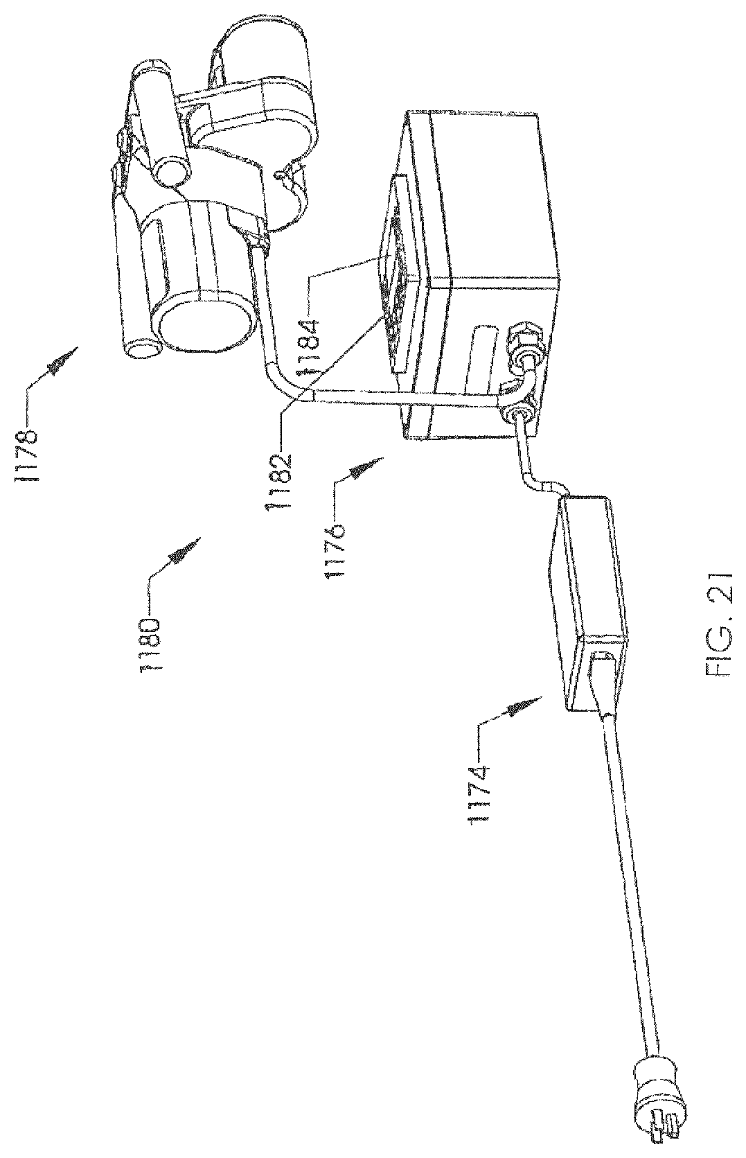
D00013
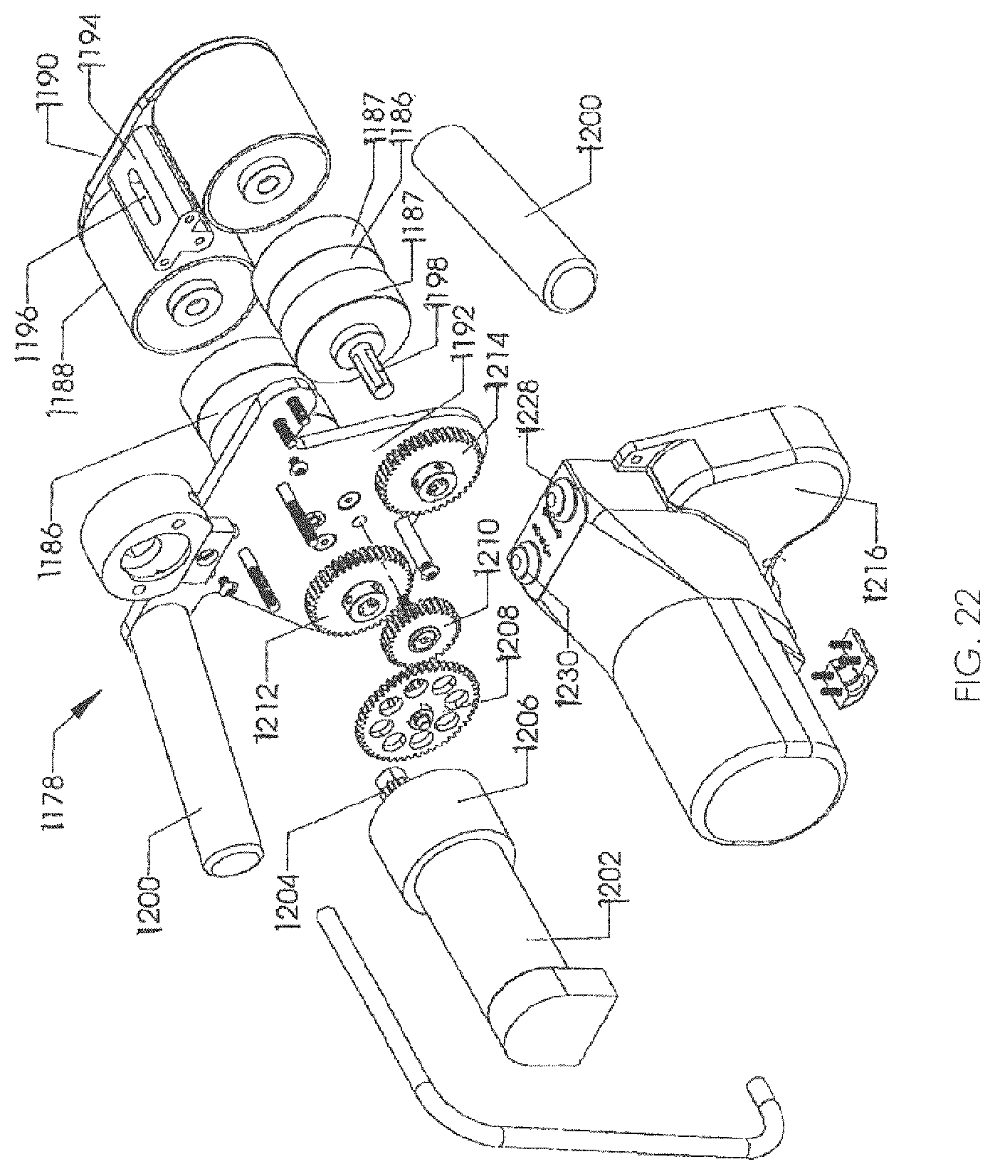
D00014
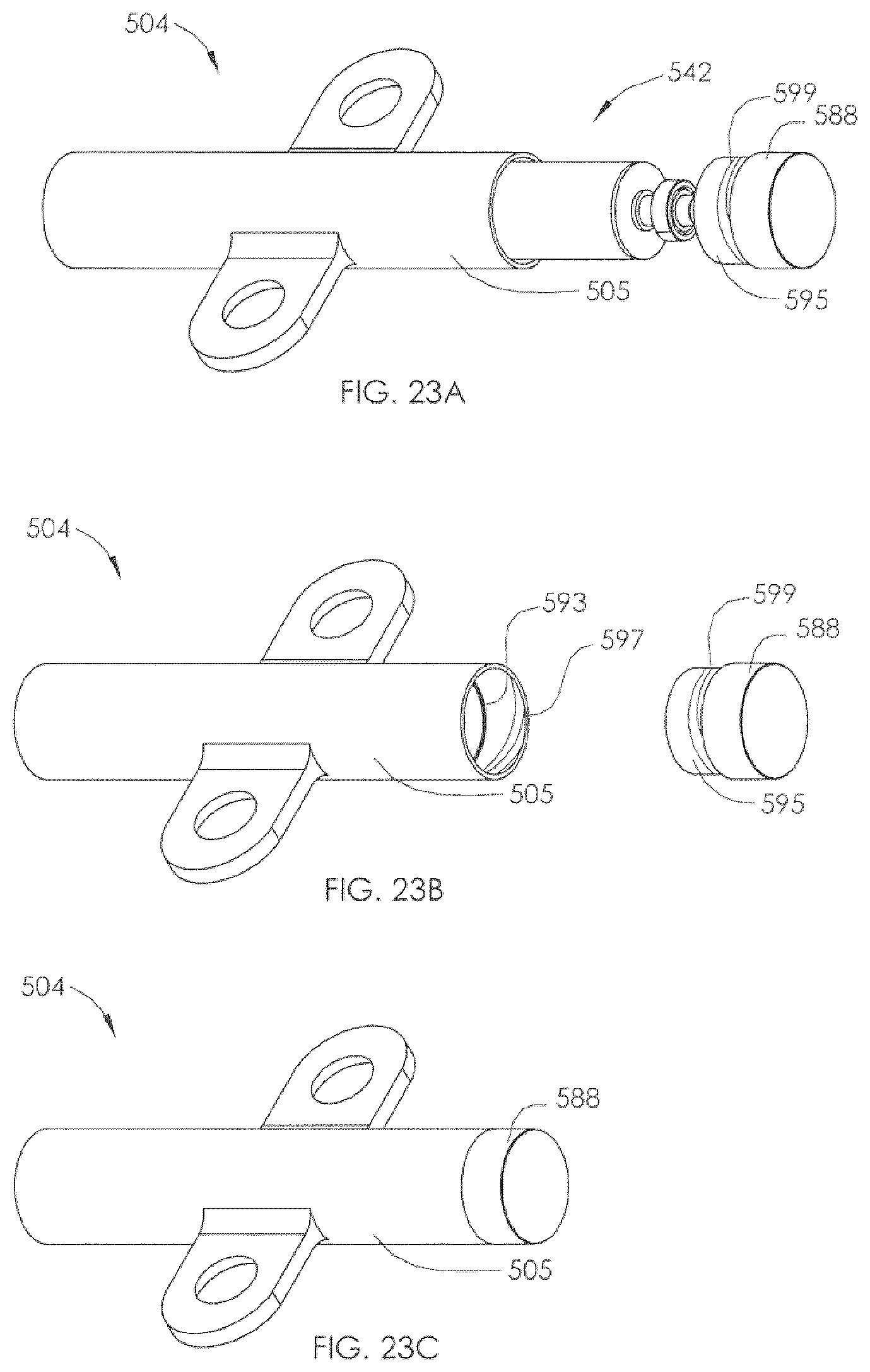
D00015

D00016

D00017

D00018
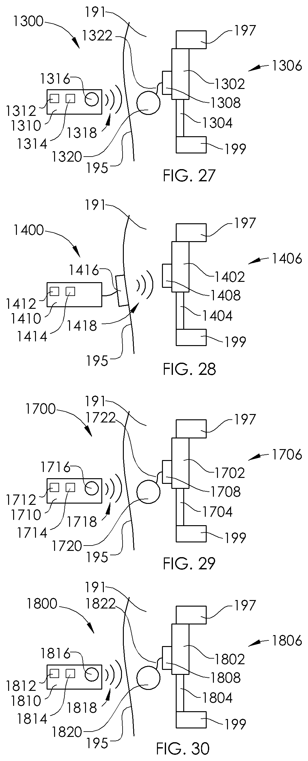
XML
uspto.report is an independent third-party trademark research tool that is not affiliated, endorsed, or sponsored by the United States Patent and Trademark Office (USPTO) or any other governmental organization. The information provided by uspto.report is based on publicly available data at the time of writing and is intended for informational purposes only.
While we strive to provide accurate and up-to-date information, we do not guarantee the accuracy, completeness, reliability, or suitability of the information displayed on this site. The use of this site is at your own risk. Any reliance you place on such information is therefore strictly at your own risk.
All official trademark data, including owner information, should be verified by visiting the official USPTO website at www.uspto.gov. This site is not intended to replace professional legal advice and should not be used as a substitute for consulting with a legal professional who is knowledgeable about trademark law.