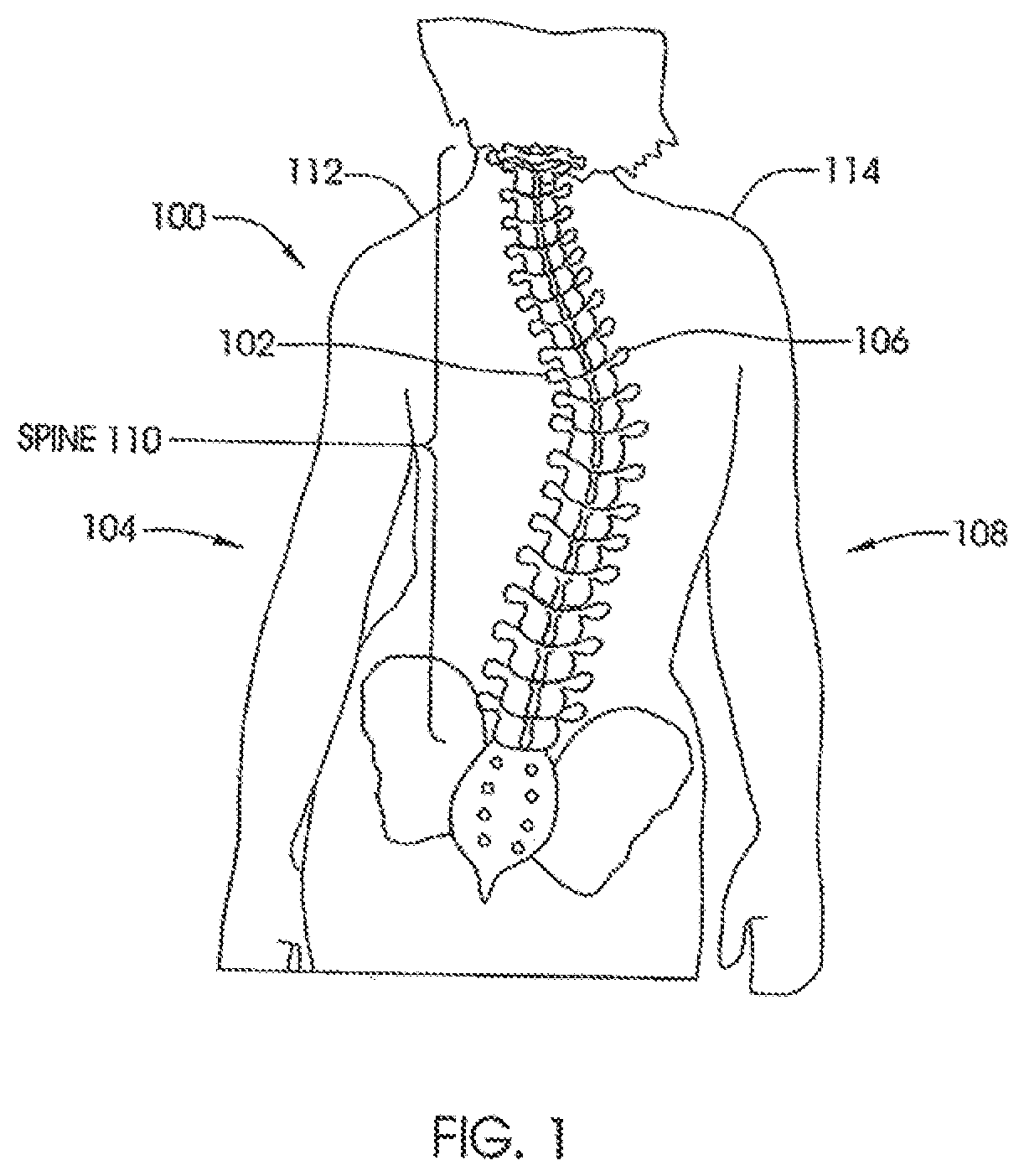
External adjustment device for distraction device
Pool , et al.
U.S. patent number 10,729,470 [Application Number 15/986,496] was granted by the patent office on 2020-08-04 for external adjustment device for distraction device. This patent grant is currently assigned to NuVasive Specialized Orthopedics, Inc.. The grantee listed for this patent is NuVasive Specialized Orthopedics, Inc.. Invention is credited to Arvin Chang, Scott Pool, Blair Walker.


View All Diagrams
| United States Patent | 10,729,470 |
| Pool , et al. | August 4, 2020 |
External adjustment device for distraction device
Abstract
A method of positioning an external adjustment device relative to a patient includes placing a magnetic viewing sheet adjacent to a patient and identifying the location of an implanted magnetic assembly using the magnetic viewing sheet by visualizing a magnetic image of the implanted magnetic assembly in the magnetic viewing sheet. The external adjustment device is placed on the patient adjacent to the location where the magnetic image was located.
| Inventors: | Pool; Scott (Laguna Hills, CA), Walker; Blair (Mission Viejo, CA), Chang; Arvin (Yorba Linda, CA) | ||||||||||
|---|---|---|---|---|---|---|---|---|---|---|---|
| Applicant: |
|
||||||||||
| Assignee: | NuVasive Specialized Orthopedics,
Inc. (San Diego, CA) |
||||||||||
| Family ID: | 1000004961881 | ||||||||||
| Appl. No.: | 15/986,496 | ||||||||||
| Filed: | May 22, 2018 |
Prior Publication Data
| Document Identifier | Publication Date | |
|---|---|---|
| US 20180280060 A1 | Oct 4, 2018 | |
Related U.S. Patent Documents
| Application Number | Filing Date | Patent Number | Issue Date | ||
|---|---|---|---|---|---|
| 14885227 | Oct 16, 2015 | 10004537 | |||
| 13747028 | Nov 4, 2015 | 9192411 | |||
| 12615855 | Feb 26, 2013 | 8382756 | |||
| 61240071 | Sep 4, 2009 | ||||
| 61113086 | Nov 10, 2008 | ||||
| Current U.S. Class: | 1/1 |
| Current CPC Class: | A61B 17/60 (20130101); A61B 17/7011 (20130101); A61B 17/7016 (20130101); A61B 17/7004 (20130101); A61B 2017/00411 (20130101); A61B 17/7216 (20130101); A61B 2017/00199 (20130101); A61B 2017/00212 (20130101) |
| Current International Class: | A61B 17/70 (20060101); A61B 17/60 (20060101); A61B 17/72 (20060101); A61B 17/00 (20060101) |
References Cited [Referenced By]
U.S. Patent Documents
| 1599538 | September 1926 | Ludger |
| 3111945 | November 1963 | Von |
| 3372476 | March 1968 | Richard et al. |
| 3377576 | April 1968 | Edwin et al. |
| 3397928 | August 1968 | Galle |
| 3512901 | May 1970 | Law |
| 3527220 | September 1970 | Summers |
| 3597781 | August 1971 | Eibes et al. |
| 3726279 | April 1973 | Barefoot et al. |
| 3749098 | July 1973 | De Bennetot |
| 3750194 | August 1973 | Summers |
| 3810259 | May 1974 | Summers |
| 3840018 | October 1974 | Heifetz |
| 3866510 | February 1975 | Eibes et al. |
| 3900025 | August 1975 | Barnes, Jr. |
| 3915151 | October 1975 | Kraus |
| RE28907 | July 1976 | Eibes et al. |
| 3976060 | August 1976 | Hildebrandt et al. |
| 4010758 | March 1977 | Rockland et al. |
| 4056743 | November 1977 | Clifford et al. |
| 4068821 | January 1978 | Morrison |
| 4078559 | March 1978 | Nissinen |
| 4118805 | October 1978 | Reimels |
| 4204541 | May 1980 | Kapitanov |
| 4222374 | September 1980 | Sampson et al. |
| 4235246 | November 1980 | Weiss |
| 4256094 | March 1981 | Kapp et al. |
| 4286584 | September 1981 | Sampson et al. |
| 4300223 | November 1981 | Make |
| 4357946 | November 1982 | Dutcher et al. |
| 4386603 | June 1983 | Mayfield |
| 4395259 | July 1983 | Prestele et al. |
| 4448191 | May 1984 | Rodnyansky et al. |
| 4486176 | December 1984 | Tardieu et al. |
| 4501266 | February 1985 | McDaniel |
| 4522501 | June 1985 | Shannon |
| 4537520 | August 1985 | Ochiai et al. |
| 4550279 | October 1985 | Klein |
| 4561798 | December 1985 | Elcrin et al. |
| 4573454 | March 1986 | Hoffman |
| 4592339 | June 1986 | Kuzmak et al. |
| 4592355 | June 1986 | Antebi |
| 4595007 | June 1986 | Mericle |
| 4642257 | February 1987 | Chase |
| 4658809 | April 1987 | Ulrich et al. |
| 4696288 | September 1987 | Kuzmak et al. |
| 4700091 | October 1987 | Wuthrich |
| 4747832 | May 1988 | Buffet |
| 4760837 | August 1988 | Petit |
| 4854304 | August 1989 | Zielke |
| 4872515 | October 1989 | Lundell |
| 4904861 | February 1990 | Epstein et al. |
| 4931055 | June 1990 | Bumpus et al. |
| 4940467 | July 1990 | Tronzo |
| 4957495 | September 1990 | Kluger |
| 4973331 | November 1990 | Pursley et al. |
| 4978323 | December 1990 | Freedman |
| 4998013 | March 1991 | Epstein et al. |
| 5010879 | April 1991 | Moriya et al. |
| 5030235 | July 1991 | Campbell, Jr. |
| 5041112 | August 1991 | Mingozzi et al. |
| 5053047 | October 1991 | Yoon |
| 5064004 | November 1991 | Lundell |
| 5074868 | December 1991 | Kuzmak |
| 5074882 | December 1991 | Grammont et al. |
| 5092889 | March 1992 | Campbell, Jr. |
| 5133716 | July 1992 | Plaza |
| 5142407 | August 1992 | Varaprasad et al. |
| 5152770 | October 1992 | Bengmark et al. |
| 5156605 | October 1992 | Pursley et al. |
| 5176618 | January 1993 | Freedman |
| 5180380 | January 1993 | Pursley et al. |
| 5222976 | June 1993 | Yoon |
| 5226429 | July 1993 | Kuzmak |
| 5261908 | November 1993 | Campbell, Jr. |
| 5263955 | November 1993 | Baumgart et al. |
| 5290289 | March 1994 | Sanders et al. |
| 5306275 | April 1994 | Bryan |
| 5330503 | July 1994 | Yoon |
| 5334202 | August 1994 | Carter |
| 5336223 | August 1994 | Rogers |
| 5356411 | October 1994 | Spievack |
| 5356424 | October 1994 | Buzerak et al. |
| 5360407 | November 1994 | Leonard et al. |
| 5364396 | November 1994 | Robinson et al. |
| 5381943 | January 1995 | Allen et al. |
| 5399168 | March 1995 | Wadsworth, Jr. et al. |
| 5403322 | April 1995 | Herzenberg et al. |
| 5429638 | July 1995 | Muschler et al. |
| 5433721 | July 1995 | Hooven et al. |
| 5437266 | August 1995 | McPherson et al. |
| 5449368 | September 1995 | Kuzmak |
| 5466261 | November 1995 | Richelsoph |
| 5468030 | November 1995 | Walling |
| 5480437 | January 1996 | Draenert |
| 5498262 | March 1996 | Bryan |
| 5509888 | April 1996 | Miller |
| 5516335 | May 1996 | Kummer et al. |
| 5527309 | June 1996 | Shelton |
| 5536269 | July 1996 | Spievack |
| 5536296 | July 1996 | Ten Eyck et al. |
| 5549610 | August 1996 | Russell et al. |
| 5573496 | November 1996 | McPherson et al. |
| 5575790 | November 1996 | Chen et al. |
| 5582616 | December 1996 | Bolduc et al. |
| 5595563 | January 1997 | Moisdon |
| 5601224 | February 1997 | Bishop et al. |
| 5620445 | April 1997 | Brosnahan et al. |
| 5620449 | April 1997 | Faccioli et al. |
| 5626579 | May 1997 | Muschler et al. |
| 5626613 | May 1997 | Schmieding |
| 5628888 | May 1997 | Bakhir et al. |
| 5632744 | May 1997 | Campbell, Jr. |
| 5659217 | August 1997 | Petersen |
| 5662683 | September 1997 | Kay |
| 5672175 | September 1997 | Martin |
| 5672177 | September 1997 | Seldin |
| 5676162 | October 1997 | Larson, Jr. et al. |
| 5693091 | December 1997 | Larson, Jr. et al. |
| 5700263 | December 1997 | Schendel |
| 5702430 | December 1997 | Larson, Jr. et al. |
| 5704893 | January 1998 | Timm |
| 5704938 | January 1998 | Staehlin et al. |
| 5704939 | January 1998 | Justin |
| 5720746 | February 1998 | Soubeiran |
| 5722429 | March 1998 | Larson, Jr. et al. |
| 5722930 | March 1998 | Larson, Jr. et al. |
| 5743910 | April 1998 | Bays et al. |
| 5758666 | June 1998 | Larson, Jr. et al. |
| 5762599 | June 1998 | Sohn |
| 5766208 | June 1998 | McEwan |
| 5771903 | June 1998 | Jakobsson |
| 5800434 | September 1998 | Campbell, Jr. |
| 5810815 | September 1998 | Morales |
| 5824008 | October 1998 | Bolduc et al. |
| 5827286 | October 1998 | Incavo et al. |
| 5829662 | November 1998 | Allen et al. |
| 5830221 | November 1998 | Stein et al. |
| 5843129 | December 1998 | Larson, Jr. et al. |
| 5874796 | February 1999 | Petersen |
| 5879375 | March 1999 | Larson, Jr. et al. |
| 5902304 | May 1999 | Walker et al. |
| 5935127 | August 1999 | Border |
| 5938669 | August 1999 | Klaiber et al. |
| 5945762 | August 1999 | Chen et al. |
| 5954915 | September 1999 | Voorhees et al. |
| 5961553 | October 1999 | Coty et al. |
| 5964763 | October 1999 | Incavo et al. |
| 5976138 | November 1999 | Baumgart et al. |
| 5979456 | November 1999 | Magovern |
| 5985110 | November 1999 | Bakhir et al. |
| 5997490 | December 1999 | McLeod et al. |
| 6009837 | January 2000 | McClasky |
| 6022349 | February 2000 | McLeod et al. |
| 6033412 | March 2000 | Losken et al. |
| 6034296 | March 2000 | Elvin et al. |
| 6067991 | May 2000 | Forsell |
| 6074341 | June 2000 | Anderson et al. |
| 6074882 | June 2000 | Eckardt |
| 6092531 | July 2000 | Chen et al. |
| 6102922 | August 2000 | Jakobsson et al. |
| 6106525 | August 2000 | Sachse |
| 6126660 | October 2000 | Dietz |
| 6126661 | October 2000 | Faccioli et al. |
| 6138681 | October 2000 | Chen et al. |
| 6139316 | October 2000 | Sachdeva et al. |
| 6162223 | December 2000 | Orsak et al. |
| 6183476 | February 2001 | Gerhardt et al. |
| 6200317 | March 2001 | Aalsma et al. |
| 6210347 | April 2001 | Forsell |
| 6217847 | April 2001 | Contag et al. |
| 6221074 | April 2001 | Cole et al. |
| 6234299 | May 2001 | Voorhees et al. |
| 6234956 | May 2001 | He et al. |
| 6241730 | June 2001 | Alby |
| 6245075 | June 2001 | Betz et al. |
| 6283156 | September 2001 | Motley |
| 6296643 | October 2001 | Hopf et al. |
| 6296656 | October 2001 | Bolduc et al. |
| 6299613 | October 2001 | Ogilvie et al. |
| 6315784 | November 2001 | Djurovic |
| 6319255 | November 2001 | Grundei et al. |
| 6321106 | November 2001 | Lemelson |
| 6325805 | December 2001 | Ogilvie et al. |
| 6327492 | December 2001 | Lemelson |
| 6331744 | December 2001 | Chen et al. |
| 6336929 | January 2002 | Justin |
| 6343568 | February 2002 | McClasky |
| 6358283 | March 2002 | Hogfors et al. |
| 6375682 | April 2002 | Fleischmann et al. |
| 6386083 | May 2002 | Hwang |
| 6389187 | May 2002 | Greenaway et al. |
| 6400980 | June 2002 | Lemelson |
| 6402753 | June 2002 | Cole et al. |
| 6409175 | June 2002 | Evans et al. |
| 6416516 | July 2002 | Stauch et al. |
| 6417750 | July 2002 | Sohn |
| 6423061 | July 2002 | Bryant |
| 6432040 | August 2002 | Meah |
| 6450173 | September 2002 | Forsell |
| 6450946 | September 2002 | Forsell |
| 6453907 | September 2002 | Forsell |
| 6454698 | September 2002 | Forsell |
| 6454699 | September 2002 | Forsell |
| 6454700 | September 2002 | Forsell |
| 6454701 | September 2002 | Forsell |
| 6460543 | October 2002 | Forsell |
| 6461292 | October 2002 | Forsell |
| 6461293 | October 2002 | Forsell |
| 6463935 | October 2002 | Forsell |
| 6464628 | October 2002 | Forsell |
| 6470892 | October 2002 | Forsell |
| 6471635 | October 2002 | Forsell |
| 6475136 | November 2002 | Forsell |
| 6482145 | November 2002 | Forsell |
| 6494879 | December 2002 | Lennox et al. |
| 6499907 | December 2002 | Baur |
| 6500110 | December 2002 | Davey et al. |
| 6503189 | January 2003 | Forsell |
| 6508820 | January 2003 | Bales |
| 6510345 | January 2003 | Van Bentem |
| 6511490 | January 2003 | Robert |
| 6527701 | March 2003 | Sayet et al. |
| 6527702 | March 2003 | Whalen et al. |
| 6536499 | March 2003 | Voorhees et al. |
| 6537196 | March 2003 | Creighton, IV et al. |
| 6547801 | April 2003 | Dargent et al. |
| 6554831 | April 2003 | Rivard et al. |
| 6558400 | May 2003 | Deem et al. |
| 6562051 | May 2003 | Bolduc et al. |
| 6565573 | May 2003 | Ferrante et al. |
| 6565576 | May 2003 | Stauch et al. |
| 6573706 | June 2003 | Mendes et al. |
| 6582313 | June 2003 | Perrow |
| 6583630 | June 2003 | Mendes et al. |
| 6587719 | July 2003 | Barrett et al. |
| 6595912 | July 2003 | Lau et al. |
| 6602184 | August 2003 | Lau et al. |
| 6604529 | August 2003 | Kim |
| 6607363 | August 2003 | Domroese |
| 6609025 | August 2003 | Barrett et al. |
| 6612978 | September 2003 | Lau et al. |
| 6612979 | September 2003 | Lau et al. |
| 6616669 | September 2003 | Ogilvie et al. |
| 6621956 | September 2003 | Greenaway et al. |
| 6626899 | September 2003 | Houser et al. |
| 6626917 | September 2003 | Craig |
| 6627206 | September 2003 | Lloyd |
| 6649143 | November 2003 | Contag et al. |
| 6656135 | December 2003 | Zogbi et al. |
| 6656194 | December 2003 | Gannoe et al. |
| 6657351 | December 2003 | Chen et al. |
| 6667725 | December 2003 | Simons et al. |
| 6669687 | December 2003 | Saadat |
| 6673079 | January 2004 | Kane |
| 6676674 | January 2004 | Dudai |
| 6682474 | January 2004 | Lau et al. |
| 6689046 | February 2004 | Sayet et al. |
| 6702732 | March 2004 | Lau et al. |
| 6702816 | March 2004 | Buhler |
| 6706042 | March 2004 | Taylor |
| 6709293 | March 2004 | Mori et al. |
| 6709385 | March 2004 | Forsell |
| 6730087 | May 2004 | Butsch |
| 6749556 | June 2004 | Banik |
| 6752754 | June 2004 | Feng et al. |
| 6761503 | July 2004 | Breese |
| 6765330 | July 2004 | Baur |
| 6769499 | August 2004 | Cargill et al. |
| 6773437 | August 2004 | Ogilvie et al. |
| 6774624 | August 2004 | Anderson et al. |
| 6789442 | September 2004 | Forch |
| 6796984 | September 2004 | Soubeiran |
| 6802844 | October 2004 | Ferree |
| 6802847 | October 2004 | Carson et al. |
| 6809434 | October 2004 | Duncan et al. |
| 6835183 | December 2004 | Lennox et al. |
| 6835207 | December 2004 | Zacouto et al. |
| 6849076 | February 2005 | Blunn et al. |
| 6852113 | February 2005 | Nathanson et al. |
| 6864647 | March 2005 | Duncan et al. |
| 6884248 | April 2005 | Bolduc et al. |
| 6890515 | May 2005 | Contag et al. |
| 6908605 | June 2005 | Contag et al. |
| 6915165 | July 2005 | Forsell |
| 6916462 | July 2005 | Contag et al. |
| 6918838 | July 2005 | Schwarzler et al. |
| 6918910 | July 2005 | Smith et al. |
| 6921360 | July 2005 | Banik |
| 6921400 | July 2005 | Sohngen |
| 6923951 | August 2005 | Contag et al. |
| 6926719 | August 2005 | Sohngen et al. |
| 6939533 | September 2005 | Contag et al. |
| 6953429 | October 2005 | Forsell |
| 6961553 | November 2005 | Zhao et al. |
| 6971143 | December 2005 | Domroese |
| 6980921 | December 2005 | Anderson et al. |
| 6997952 | February 2006 | Furukawa et al. |
| 7001327 | February 2006 | Whalen et al. |
| 7001346 | February 2006 | White |
| 7008425 | March 2006 | Phillips |
| 7011621 | March 2006 | Sayet et al. |
| 7011658 | March 2006 | Young |
| 7011682 | March 2006 | Lashinski et al. |
| 7018380 | March 2006 | Cole |
| 7029475 | April 2006 | Panjabi |
| 7041105 | May 2006 | Michelson |
| 7060075 | June 2006 | Govari et al. |
| 7060080 | June 2006 | Bachmann |
| 7063706 | June 2006 | Wittenstein |
| 7077802 | July 2006 | Lau et al. |
| 7081086 | July 2006 | Lau et al. |
| 7083629 | August 2006 | Weller et al. |
| 7096148 | August 2006 | Anderson et al. |
| 7097611 | August 2006 | Lau et al. |
| 7105029 | September 2006 | Doubler et al. |
| 7105968 | September 2006 | Nissen |
| 7114501 | October 2006 | Johnson et al. |
| 7115129 | October 2006 | Heggeness |
| 7115130 | October 2006 | Michelson |
| 7124493 | October 2006 | Lau et al. |
| 7128707 | October 2006 | Banik |
| 7135022 | November 2006 | Kosashvili et al. |
| 7160312 | January 2007 | Saadat |
| 7163538 | January 2007 | Altarac et al. |
| 7172607 | February 2007 | Hofle et al. |
| 7175589 | February 2007 | Deem et al. |
| 7175660 | February 2007 | Cartledge et al. |
| 7186262 | March 2007 | Saadat |
| 7188627 | March 2007 | Nelson et al. |
| 7189005 | March 2007 | Ward |
| 7189202 | March 2007 | Lau et al. |
| 7189251 | March 2007 | Kay |
| 7191007 | March 2007 | Desai et al. |
| 7194297 | March 2007 | Talpade et al. |
| 7195608 | March 2007 | Burnett |
| 7198774 | April 2007 | Contag et al. |
| 7211094 | May 2007 | Gannoe et al. |
| 7216648 | May 2007 | Nelson et al. |
| 7217284 | May 2007 | Houser et al. |
| 7218232 | May 2007 | DiSilvestro et al. |
| 7232449 | June 2007 | Sharkawy et al. |
| 7234468 | June 2007 | Johnson et al. |
| 7234544 | June 2007 | Kent |
| 7238152 | July 2007 | Lau et al. |
| 7238191 | July 2007 | Bachmann |
| 7241300 | July 2007 | Sharkawy et al. |
| 7243719 | July 2007 | Baron et al. |
| 7255682 | August 2007 | Bartol, Jr. et al. |
| 7255714 | August 2007 | Malek |
| 7255851 | August 2007 | Contag et al. |
| 7276022 | October 2007 | Lau et al. |
| 7282023 | October 2007 | Frering |
| 7285087 | October 2007 | Moaddeb et al. |
| 7288064 | October 2007 | Boustani et al. |
| 7288099 | October 2007 | Deem et al. |
| 7288101 | October 2007 | Deem et al. |
| 7296577 | November 2007 | Lashinski et al. |
| 7297150 | November 2007 | Cartledge et al. |
| 7299091 | November 2007 | Barrett et al. |
| 7302858 | December 2007 | Walsh et al. |
| 7306614 | December 2007 | Weller et al. |
| 7311690 | December 2007 | Burnett |
| 7314372 | January 2008 | Belfor et al. |
| 7314443 | January 2008 | Jordan et al. |
| 7320706 | January 2008 | Al-Najjar |
| 7331995 | February 2008 | Eisermann et al. |
| 7333013 | February 2008 | Berger |
| 7338433 | March 2008 | Coe |
| 7340306 | March 2008 | Barrett et al. |
| 7351198 | April 2008 | Byrum et al. |
| 7351240 | April 2008 | Hassler, Jr. et al. |
| 7353747 | April 2008 | Swayze et al. |
| 7357037 | April 2008 | Hnat et al. |
| 7357635 | April 2008 | Belfor et al. |
| 7360542 | April 2008 | Nelson et al. |
| 7361192 | April 2008 | Doty |
| 7364542 | April 2008 | Jambor et al. |
| 7364589 | April 2008 | Eisermann |
| 7367340 | May 2008 | Nelson et al. |
| 7367937 | May 2008 | Jambor et al. |
| 7367938 | May 2008 | Forsell |
| 7371244 | May 2008 | Chatlynne et al. |
| 7374557 | May 2008 | Conlon et al. |
| 7390007 | June 2008 | Helms et al. |
| 7390294 | June 2008 | Hassler, Jr. |
| 7400926 | July 2008 | Forsell |
| 7402134 | July 2008 | Moaddeb et al. |
| 7402176 | July 2008 | Malek |
| 7410461 | August 2008 | Lau et al. |
| 7416528 | August 2008 | Crawford et al. |
| 7422566 | September 2008 | Miethke |
| 7429259 | September 2008 | Cadeddu et al. |
| 7431692 | October 2008 | Zollinger et al. |
| 7441559 | October 2008 | Nelson et al. |
| 7442196 | October 2008 | Fisher et al. |
| 7445010 | November 2008 | Kugler et al. |
| 7455690 | November 2008 | Cartledge et al. |
| 7458981 | December 2008 | Fielding et al. |
| 7468060 | December 2008 | Utley et al. |
| 7476195 | January 2009 | Sayet et al. |
| 7476238 | January 2009 | Panjabi |
| 7481224 | January 2009 | Nelson et al. |
| 7481763 | January 2009 | Hassler, Jr. et al. |
| 7481841 | January 2009 | Hazebrouck et al. |
| 7485149 | February 2009 | White |
| 7489495 | February 2009 | Stevenson |
| 7494459 | February 2009 | Anstadt et al. |
| 7500484 | March 2009 | Nelson et al. |
| 7503922 | March 2009 | Deem et al. |
| 7503934 | March 2009 | Eisermann et al. |
| 7507252 | March 2009 | Lashinski et al. |
| 7510559 | March 2009 | Deem et al. |
| 7530981 | May 2009 | Kutsenko |
| 7531002 | May 2009 | Sutton et al. |
| 7547291 | June 2009 | Lennox et al. |
| 7553298 | June 2009 | Hunt et al. |
| 7559951 | July 2009 | DiSilvestro et al. |
| 7561916 | July 2009 | Hunt et al. |
| 7562660 | July 2009 | Saadat |
| 7566297 | July 2009 | Banik |
| 7569057 | August 2009 | Liu et al. |
| 7578821 | August 2009 | Fisher et al. |
| 7584788 | September 2009 | Baron et al. |
| 7594887 | September 2009 | Moaddeb et al. |
| 7601156 | October 2009 | Robinson |
| 7601162 | October 2009 | Hassler, Jr. et al. |
| 7601171 | October 2009 | Ainsworth et al. |
| 7611526 | November 2009 | Carl et al. |
| 7615001 | November 2009 | Jambor et al. |
| 7615068 | November 2009 | Timm et al. |
| 7618435 | November 2009 | Opolski |
| 7621886 | November 2009 | Burnett |
| 7635379 | December 2009 | Callahan et al. |
| 7651483 | January 2010 | Byrum et al. |
| 7658753 | February 2010 | Carl et al. |
| 7666132 | February 2010 | Forsell |
| 7666184 | February 2010 | Stauch |
| 7666210 | February 2010 | Franck et al. |
| 7678136 | March 2010 | Doubler et al. |
| 7678139 | March 2010 | Garamszegi et al. |
| 7691144 | April 2010 | Chang et al. |
| 7695512 | April 2010 | Lashinski et al. |
| 7704279 | April 2010 | Moskowitz et al. |
| 7704282 | April 2010 | Disilvestro et al. |
| 7708737 | May 2010 | Kraft et al. |
| 7708762 | May 2010 | McCarthy et al. |
| 7708765 | May 2010 | Carl et al. |
| 7708779 | May 2010 | Edie et al. |
| 7713287 | May 2010 | Timm et al. |
| 7717959 | May 2010 | William et al. |
| 7727141 | June 2010 | Hassler, Jr. et al. |
| 7727143 | June 2010 | Birk et al. |
| 7749224 | July 2010 | Cresina et al. |
| 7753913 | July 2010 | Szakelyhidi, Jr. et al. |
| 7753915 | July 2010 | Eksler et al. |
| 7757552 | July 2010 | Bogath et al. |
| 7762998 | July 2010 | Birk et al. |
| 7763053 | July 2010 | Gordon |
| 7763080 | July 2010 | Southworth |
| 7766815 | August 2010 | Ortiz |
| 7775099 | August 2010 | Bogath et al. |
| 7775215 | August 2010 | Hassler, Jr. et al. |
| 7776061 | August 2010 | Garner et al. |
| 7776068 | August 2010 | Ainsworth et al. |
| 7776075 | August 2010 | Bruneau et al. |
| 7776091 | August 2010 | Mastrorio et al. |
| 7780590 | August 2010 | Birk et al. |
| 7787958 | August 2010 | Stevenson |
| 7789912 | September 2010 | Manzi et al. |
| 7793583 | September 2010 | Radinger et al. |
| 7794447 | September 2010 | Dann et al. |
| 7794476 | September 2010 | Wisnewski |
| 7798954 | September 2010 | Birk et al. |
| 7799080 | September 2010 | Doty |
| 7803106 | September 2010 | Whalen et al. |
| 7803157 | September 2010 | Michelson |
| 7811275 | October 2010 | Birk et al. |
| 7811298 | October 2010 | Birk |
| 7811328 | October 2010 | Molz, IV et al. |
| 7815643 | October 2010 | Johnson et al. |
| 7828714 | November 2010 | Feng et al. |
| 7828813 | November 2010 | Mouton |
| 7833228 | November 2010 | Hershberger |
| 7835779 | November 2010 | Anderson et al. |
| 7837669 | November 2010 | Dann et al. |
| 7837691 | November 2010 | Cordes et al. |
| 7842036 | November 2010 | Phillips |
| 7845356 | December 2010 | Paraschac et al. |
| 7846188 | December 2010 | Moskowitz et al. |
| 7850660 | December 2010 | Uth et al. |
| 7850735 | December 2010 | Eisermann et al. |
| 7854769 | December 2010 | Hershberger |
| 7862502 | January 2011 | Pool |
| 7862546 | January 2011 | Conlon et al. |
| 7862574 | January 2011 | Deem et al. |
| 7862586 | January 2011 | Malek |
| 7867235 | January 2011 | Fell et al. |
| 7871368 | January 2011 | Zollinger et al. |
| 7875033 | January 2011 | Richter et al. |
| 7887566 | February 2011 | Hynes |
| 7901381 | March 2011 | Birk et al. |
| 7901419 | March 2011 | Bachmann et al. |
| 7909790 | March 2011 | Burnett |
| 7909838 | March 2011 | Deem et al. |
| 7909839 | March 2011 | Fields |
| 7909852 | March 2011 | Boomer et al. |
| 7918844 | April 2011 | Byrum et al. |
| 7921850 | April 2011 | Nelson et al. |
| 7922765 | April 2011 | Reiley |
| 7927354 | April 2011 | Edidin et al. |
| 7927357 | April 2011 | Sacher et al. |
| 7931679 | April 2011 | Heggeness |
| 7932825 | April 2011 | Berger |
| 7938836 | May 2011 | Ainsworth et al. |
| 7938841 | May 2011 | Sharkawy et al. |
| 7942903 | May 2011 | Moskowitz et al. |
| 7942908 | May 2011 | Sacher et al. |
| 7947011 | May 2011 | Birk et al. |
| 7951067 | May 2011 | Byrum et al. |
| 7951180 | May 2011 | Moskowitz et al. |
| 7958895 | June 2011 | Nelson et al. |
| 7958896 | June 2011 | Nelson et al. |
| 7959552 | June 2011 | Jordan et al. |
| 7972315 | July 2011 | Birk et al. |
| 7972346 | July 2011 | Bachmann et al. |
| 7972363 | July 2011 | Moskowitz et al. |
| 7976545 | July 2011 | Hershberger et al. |
| 7983763 | July 2011 | Stevenson et al. |
| 7985256 | July 2011 | Grotz et al. |
| 7987241 | July 2011 | St Jacques, Jr. et al. |
| 7988707 | August 2011 | Panjabi |
| 7988709 | August 2011 | Clark et al. |
| 7993342 | August 2011 | Malandain et al. |
| 7993397 | August 2011 | Lashinski et al. |
| 7998174 | August 2011 | Malandain et al. |
| 7998208 | August 2011 | Kohm et al. |
| 8002801 | August 2011 | Carl et al. |
| 8002809 | August 2011 | Baynham |
| 8007458 | August 2011 | Lennox et al. |
| 8007474 | August 2011 | Uth et al. |
| 8007479 | August 2011 | Birk et al. |
| 8011308 | September 2011 | Picchio |
| 8012162 | September 2011 | Bachmann |
| 8016745 | September 2011 | Hassler, Jr. et al. |
| 8016837 | September 2011 | Giger et al. |
| 8016860 | September 2011 | Carl et al. |
| 8026729 | September 2011 | Kroh et al. |
| 8029477 | October 2011 | Byrum et al. |
| 8029567 | October 2011 | Edidin et al. |
| 8034080 | October 2011 | Malandain et al. |
| 8037871 | October 2011 | McClendon |
| 8038680 | October 2011 | Ainsworth et al. |
| 8038698 | October 2011 | Edidin et al. |
| 8043206 | October 2011 | Birk |
| 8043290 | October 2011 | Harrison et al. |
| 8043299 | October 2011 | Conway |
| 8043338 | October 2011 | Dant |
| 8043345 | October 2011 | Carl et al. |
| 8048169 | November 2011 | Burnett et al. |
| 8057473 | November 2011 | Orsak et al. |
| 8057513 | November 2011 | Kohm et al. |
| 8066650 | November 2011 | Lee et al. |
| 8070670 | December 2011 | Deem et al. |
| 8070671 | December 2011 | Deem et al. |
| 8070695 | December 2011 | Gupta et al. |
| 8070813 | December 2011 | Grotz et al. |
| 8074654 | December 2011 | Paraschac et al. |
| 8075577 | December 2011 | Deem et al. |
| 8079974 | December 2011 | Stergiopulos |
| 8079989 | December 2011 | Birk et al. |
| 8080022 | December 2011 | Deem et al. |
| 8080025 | December 2011 | Deem et al. |
| 8088166 | January 2012 | Makower et al. |
| 8092459 | January 2012 | Malandain |
| 8092499 | January 2012 | Roth |
| 8095317 | January 2012 | Ekseth et al. |
| 8096302 | January 2012 | Nelson et al. |
| 8096938 | January 2012 | Forsell |
| 8096995 | January 2012 | Kohm et al. |
| 8097018 | January 2012 | Malandain et al. |
| 8097038 | January 2012 | Malek |
| 8100819 | January 2012 | Banik |
| 8100943 | January 2012 | Malandain et al. |
| 8100967 | January 2012 | Makower et al. |
| 8105360 | January 2012 | Connor |
| 8105363 | January 2012 | Fielding et al. |
| 8105364 | January 2012 | McCarthy et al. |
| 8109974 | February 2012 | Boomer et al. |
| 8114158 | February 2012 | Carl et al. |
| 8123765 | February 2012 | Deem et al. |
| 8123805 | February 2012 | Makower et al. |
| 8128628 | March 2012 | Freid et al. |
| 8133280 | March 2012 | Voellmicke et al. |
| 8137349 | March 2012 | Soubeiran |
| 8137366 | March 2012 | Deem et al. |
| 8137367 | March 2012 | Deem et al. |
| 8142454 | March 2012 | Harrison et al. |
| 8142494 | March 2012 | Randert et al. |
| 8147517 | April 2012 | Trieu et al. |
| 8147549 | April 2012 | Metcalf, Jr. et al. |
| 8157841 | April 2012 | Malandain et al. |
| 8162897 | April 2012 | Byrum |
| 8162979 | April 2012 | Sachs et al. |
| 8163013 | April 2012 | Machold et al. |
| 8177789 | May 2012 | Magill et al. |
| 8182411 | May 2012 | Dlugos |
| 8187324 | May 2012 | Webler et al. |
| 8197544 | June 2012 | Manzi et al. |
| 8202305 | June 2012 | Reiley |
| 8211127 | July 2012 | Uth et al. |
| 8211149 | July 2012 | Justis |
| 8211151 | July 2012 | Schwab et al. |
| 8211179 | July 2012 | Molz, IV et al. |
| 8216275 | July 2012 | Fielding et al. |
| 8221420 | July 2012 | Keller |
| 8226690 | July 2012 | Altarac et al. |
| 8236002 | August 2012 | Fortin et al. |
| 8241292 | August 2012 | Collazo |
| 8241293 | August 2012 | Stone et al. |
| 8241331 | August 2012 | Arnin |
| 8246630 | August 2012 | Manzi et al. |
| 8251888 | August 2012 | Roslin et al. |
| 8252063 | August 2012 | Stauch |
| 8257370 | September 2012 | Moskowitz et al. |
| 8257442 | September 2012 | Edie et al. |
| 8263024 | September 2012 | Wan et al. |
| 8267969 | September 2012 | Altarac et al. |
| 8273112 | September 2012 | Garamszegi et al. |
| 8278941 | October 2012 | Kroh et al. |
| 8282671 | October 2012 | Connor |
| 8287540 | October 2012 | LeCronier et al. |
| 8298133 | October 2012 | Wiley et al. |
| 8298240 | October 2012 | Giger et al. |
| 8308779 | November 2012 | Reiley |
| 8313423 | November 2012 | Forsell |
| 8316856 | November 2012 | Nelson et al. |
| 8317761 | November 2012 | Birk et al. |
| 8317802 | November 2012 | Manzi et al. |
| 8323290 | December 2012 | Metzger et al. |
| 8326435 | December 2012 | Stevenson |
| 8328807 | December 2012 | Brigido |
| 8328854 | December 2012 | Baynham et al. |
| 8333204 | December 2012 | Saadat |
| 8333790 | December 2012 | Timm et al. |
| 8353913 | January 2013 | Moskowitz et al. |
| 8357169 | January 2013 | Henniges et al. |
| 8357182 | January 2013 | Seme |
| 8357183 | January 2013 | Seme et al. |
| 8360955 | January 2013 | Sayet et al. |
| 8366628 | February 2013 | Denker et al. |
| 8372078 | February 2013 | Collazo |
| 8382652 | February 2013 | Sayet et al. |
| 8386018 | February 2013 | Stauch et al. |
| 8388667 | March 2013 | Reiley et al. |
| 8394124 | March 2013 | Biyani |
| 8394143 | March 2013 | Grotz et al. |
| 8403958 | March 2013 | Schwab |
| 8409203 | April 2013 | Birk et al. |
| 8409281 | April 2013 | Makower et al. |
| 8414584 | April 2013 | Brigido |
| 8414648 | April 2013 | Reiley |
| 8419755 | April 2013 | Deem et al. |
| 8419801 | April 2013 | DiSilvestro et al. |
| 8425570 | April 2013 | Reiley |
| 8425608 | April 2013 | Dewey et al. |
| 8433519 | April 2013 | Ekseth et al. |
| 8435268 | May 2013 | Thompson et al. |
| 8439915 | May 2013 | Harrison et al. |
| 8439926 | May 2013 | Bojarski et al. |
| 8444693 | May 2013 | Reiley |
| 8449553 | May 2013 | Kam et al. |
| 8449580 | May 2013 | Voellmicke et al. |
| 8454695 | June 2013 | Grotz et al. |
| 8469908 | June 2013 | Asfora |
| 8469978 | June 2013 | Fobi et al. |
| 8470003 | June 2013 | Voellmicke et al. |
| 8470004 | June 2013 | Reiley |
| 8475354 | July 2013 | Phillips et al. |
| 8475356 | July 2013 | Feng et al. |
| 8475499 | July 2013 | Cournoyer et al. |
| 8480554 | July 2013 | Phillips et al. |
| 8480668 | July 2013 | Fernandez et al. |
| 8480741 | July 2013 | Grotz et al. |
| 8486070 | July 2013 | Morgan et al. |
| 8486076 | July 2013 | Chavarria et al. |
| 8486110 | July 2013 | Fielding et al. |
| 8486113 | July 2013 | Malek |
| 8486147 | July 2013 | de Villiers et al. |
| 8491589 | July 2013 | Fisher et al. |
| 8494805 | July 2013 | Roche et al. |
| 8496662 | July 2013 | Novak et al. |
| 8500810 | August 2013 | Mastrorio et al. |
| 8506517 | August 2013 | Stergiopulos |
| 8506569 | August 2013 | Keefer et al. |
| 8517973 | August 2013 | Burnett |
| 8518062 | August 2013 | Cole et al. |
| 8518086 | August 2013 | Seme et al. |
| 8522790 | September 2013 | Nelson et al. |
| 8523865 | September 2013 | Reglos et al. |
| 8523866 | September 2013 | Sidebotham et al. |
| 8523883 | September 2013 | Saadat |
| 8529474 | September 2013 | Gupta et al. |
| 8529606 | September 2013 | Alamin et al. |
| 8529607 | September 2013 | Alamin et al. |
| 8529630 | September 2013 | Bojarski et al. |
| 8545384 | October 2013 | Forsell |
| 8545508 | October 2013 | Collazo |
| 8545814 | October 2013 | Contag et al. |
| 8551092 | October 2013 | Morgan et al. |
| 8551142 | October 2013 | Altarac et al. |
| 8551422 | October 2013 | Wan et al. |
| 8556901 | October 2013 | Anthony et al. |
| 8556911 | October 2013 | Mehta et al. |
| 8556975 | October 2013 | Ciupik et al. |
| 8562653 | October 2013 | Alamin et al. |
| 8568416 | October 2013 | Schmitz et al. |
| 8568457 | October 2013 | Hunziker |
| 8574267 | November 2013 | Linares |
| 8579919 | November 2013 | Bolduc et al. |
| 8579979 | November 2013 | Edie et al. |
| 8585595 | November 2013 | Heilman |
| 8585702 | November 2013 | Orsak et al. |
| 8585738 | November 2013 | Linares |
| 8585740 | November 2013 | Ross et al. |
| 8591549 | November 2013 | Lange |
| 8597362 | December 2013 | Shenoy et al. |
| 8613749 | December 2013 | Deem et al. |
| 8613758 | December 2013 | Linares |
| 8617212 | December 2013 | Linares |
| 8617220 | December 2013 | Skaggs |
| 8617243 | December 2013 | Eisermann et al. |
| 8622936 | January 2014 | Schenberger et al. |
| 8623036 | January 2014 | Harrison et al. |
| 8623042 | January 2014 | Roslin et al. |
| 8623056 | January 2014 | Linares |
| 8632544 | January 2014 | Haaja et al. |
| 8632547 | January 2014 | Maxson et al. |
| 8632548 | January 2014 | Soubeiran |
| 8632563 | January 2014 | Nagase et al. |
| 8632594 | January 2014 | Williams et al. |
| 8636770 | January 2014 | Hestad et al. |
| 8636771 | January 2014 | Butler et al. |
| 8636802 | January 2014 | Serhan et al. |
| 8641719 | February 2014 | Gephart et al. |
| 8641723 | February 2014 | Connor |
| 8652175 | February 2014 | Timm et al. |
| 8657765 | February 2014 | Asfora |
| 8657856 | February 2014 | Gephart et al. |
| 8657885 | February 2014 | Burnett et al. |
| 8663139 | March 2014 | Asfora |
| 8663140 | March 2014 | Asfora |
| 8663285 | March 2014 | Dall et al. |
| 8663287 | March 2014 | Butler et al. |
| 8663338 | March 2014 | Burnett et al. |
| 8668719 | March 2014 | Alamin et al. |
| 8673001 | March 2014 | Cartledge et al. |
| 8679161 | March 2014 | Malandain et al. |
| 8690858 | April 2014 | Machold et al. |
| 8707959 | April 2014 | Paraschac et al. |
| 8709090 | April 2014 | Makower et al. |
| 8715243 | May 2014 | Uth et al. |
| 8715290 | May 2014 | Fisher et al. |
| 8721570 | May 2014 | Gupta et al. |
| 8721643 | May 2014 | Morgan et al. |
| 8728125 | May 2014 | Bruneau et al. |
| 8734318 | May 2014 | Forsell |
| 8734516 | May 2014 | Moskowitz et al. |
| 8734519 | May 2014 | de Villiers et al. |
| 8747444 | June 2014 | Moskowitz et al. |
| 8752552 | June 2014 | Nelson et al. |
| 8758303 | June 2014 | Uth et al. |
| 8758347 | June 2014 | Weiner et al. |
| 8758355 | June 2014 | Fisher et al. |
| 8758372 | June 2014 | Cartledge et al. |
| 8762308 | June 2014 | Najarian et al. |
| 8764713 | July 2014 | Uth et al. |
| 8771272 | July 2014 | LeCronier et al. |
| 8777947 | July 2014 | Zahrly et al. |
| 8777995 | July 2014 | McClintock et al. |
| 8781744 | July 2014 | Ekseth et al. |
| 8784482 | July 2014 | Randert et al. |
| 8790343 | July 2014 | McClellan et al. |
| 8790380 | July 2014 | Buttermann |
| 8790409 | July 2014 | Van den Heuvel et al. |
| 8794243 | August 2014 | Deem et al. |
| 8795339 | August 2014 | Boomer et al. |
| 8801795 | August 2014 | Makower et al. |
| 8808206 | August 2014 | Asfora |
| 8813727 | August 2014 | McClendon |
| 8814869 | August 2014 | Freid et al. |
| 8828058 | September 2014 | Elsebaie et al. |
| 8828087 | September 2014 | Stone et al. |
| 8840623 | September 2014 | Reiley |
| 8840651 | September 2014 | Reiley |
| 8845692 | September 2014 | Wisnewski |
| 8845724 | September 2014 | Shenoy et al. |
| 8864717 | October 2014 | Conlon et al. |
| 8864823 | October 2014 | Cartledge et al. |
| 8870881 | October 2014 | Rezach et al. |
| 8870918 | October 2014 | Boomer et al. |
| 8870959 | October 2014 | Arnin |
| 8882699 | November 2014 | Burnett |
| 8882830 | November 2014 | Cartledge et al. |
| 8888672 | November 2014 | Phillips et al. |
| 8888673 | November 2014 | Phillips et al. |
| 8894663 | November 2014 | Giger et al. |
| 8915915 | December 2014 | Harrison et al. |
| 8915917 | December 2014 | Doherty et al. |
| 8920422 | December 2014 | Homeier et al. |
| 8932247 | January 2015 | Stergiopulos |
| 8945188 | February 2015 | Rezach et al. |
| 8945210 | February 2015 | Cartledge et al. |
| 8956407 | February 2015 | Macoviak et al. |
| 8961386 | February 2015 | Phillips et al. |
| 8961521 | February 2015 | Keefer et al. |
| 8961567 | February 2015 | Hunziker |
| 8968402 | March 2015 | Myers et al. |
| 8968406 | March 2015 | Arnin |
| 8986348 | March 2015 | Reiley |
| 8992527 | March 2015 | Guichet |
| 9005251 | April 2015 | Heggeness |
| 9005293 | April 2015 | Moskowitz et al. |
| 9005298 | April 2015 | Makower et al. |
| 9011491 | April 2015 | Carl et al. |
| 9015057 | April 2015 | Phillips et al. |
| 9022917 | May 2015 | Kasic et al. |
| 9028550 | May 2015 | Shulock et al. |
| 9033957 | May 2015 | Cadeddu et al. |
| 9033988 | May 2015 | Gephart et al. |
| 9034016 | May 2015 | Panjabi |
| 9044218 | June 2015 | Young |
| 9060810 | June 2015 | Kercher et al. |
| 9060844 | June 2015 | Kagan et al. |
| 9072530 | July 2015 | Mehta et al. |
| 9072606 | July 2015 | Lucas et al. |
| 9078703 | July 2015 | Arnin |
| 9084632 | July 2015 | Orsak et al. |
| 9089348 | July 2015 | Chavarria et al. |
| 9095436 | August 2015 | Boyden et al. |
| 9095437 | August 2015 | Boyden et al. |
| 9101422 | August 2015 | Freid et al. |
| 9101427 | August 2015 | Globerman et al. |
| 9107706 | August 2015 | Alamin et al. |
| 9113967 | August 2015 | Soubeiran |
| 9114016 | August 2015 | Shenoy et al. |
| 9125746 | September 2015 | Clifford et al. |
| 9138266 | September 2015 | Stauch |
| 9144482 | September 2015 | Sayet |
| 9155565 | October 2015 | Boomer et al. |
| 9161856 | October 2015 | Nelson et al. |
| 9168071 | October 2015 | Seme et al. |
| 9168076 | October 2015 | Patty et al. |
| 9173681 | November 2015 | Seme |
| 9173715 | November 2015 | Baumgartner |
| 9186158 | November 2015 | Anthony et al. |
| 9186185 | November 2015 | Hestad et al. |
| 9198771 | December 2015 | Ciupik |
| 9204899 | December 2015 | Buttermann |
| 9204908 | December 2015 | Buttermann |
| 9220536 | December 2015 | Skaggs |
| 9226783 | January 2016 | Brigido |
| 9242070 | January 2016 | Tieu |
| 9259243 | February 2016 | Giger et al. |
| 9272159 | March 2016 | Phillips et al. |
| 9278004 | March 2016 | Shenoy et al. |
| 9278046 | March 2016 | Asfora |
| 9282997 | March 2016 | Hunziker |
| 9301792 | April 2016 | Henniges et al. |
| 9301854 | April 2016 | Moskowitz et al. |
| 9308089 | April 2016 | Vicatos et al. |
| 9308387 | April 2016 | Phillips et al. |
| 9320618 | April 2016 | Schmitz et al. |
| 9326728 | May 2016 | Demir et al. |
| 9333009 | May 2016 | Kroll et al. |
| 9339197 | May 2016 | Griswold et al. |
| 9339300 | May 2016 | Kantelhardt |
| 9339307 | May 2016 | McClintock et al. |
| 9339312 | May 2016 | Doherty et al. |
| 9358044 | June 2016 | Seme et al. |
| 9364267 | June 2016 | Northcutt et al. |
| 9370388 | June 2016 | Globerman et al. |
| 9393123 | July 2016 | Lucas et al. |
| 9408644 | August 2016 | Zahrly et al. |
| 9421347 | August 2016 | Burnett |
| 9427267 | August 2016 | Homeier et al. |
| 9439744 | September 2016 | Forsell |
| 9439797 | September 2016 | Baym et al. |
| 9445848 | September 2016 | Anderson et al. |
| 9451997 | September 2016 | Carl et al. |
| 9456953 | October 2016 | Asfora |
| 9474612 | October 2016 | Haaja et al. |
| 9492199 | November 2016 | Orsak et al. |
| 9492276 | November 2016 | Lee et al. |
| 9498258 | November 2016 | Boomer et al. |
| 9498366 | November 2016 | Burnett et al. |
| 9510834 | December 2016 | Burnett et al. |
| 9532804 | January 2017 | Clifford et al. |
| 9561062 | February 2017 | Hayes et al. |
| 9561063 | February 2017 | Reiley |
| 9572588 | February 2017 | Fisher et al. |
| 9572746 | February 2017 | Asfora |
| 9572910 | February 2017 | Messersmith et al. |
| 9579110 | February 2017 | Bojarski et al. |
| 9579203 | February 2017 | Soubeiran |
| 9603605 | March 2017 | Collazo |
| 9603713 | March 2017 | Moskowitz et al. |
| 9610161 | April 2017 | Macoviak et al. |
| 9622875 | April 2017 | Moskowitz et al. |
| 9642735 | May 2017 | Burnett |
| 9655651 | May 2017 | Panjabi |
| 9668868 | June 2017 | Shenoy et al. |
| 9687243 | June 2017 | Burnett et al. |
| 9687414 | June 2017 | Asfora |
| 9693867 | July 2017 | Lucas et al. |
| 9700419 | July 2017 | Clifford et al. |
| 9700450 | July 2017 | Burnett |
| 9717537 | August 2017 | Gordon |
| 9724135 | August 2017 | Koch et al. |
| 9724265 | August 2017 | Asfora |
| 9730738 | August 2017 | Gephart et al. |
| 9743969 | August 2017 | Reiley |
| 9782206 | October 2017 | Mueckter et al. |
| 9795410 | October 2017 | Shenoy et al. |
| 9814600 | November 2017 | Shulock et al. |
| 9820789 | November 2017 | Reiley |
| 9826987 | November 2017 | Keefer et al. |
| 9833291 | December 2017 | Baumgartner |
| 9848894 | December 2017 | Burley et al. |
| 9848993 | December 2017 | Moskowitz et al. |
| 9861376 | January 2018 | Chavarria et al. |
| 9861390 | January 2018 | Hunziker |
| 9861404 | January 2018 | Reiley |
| 9867719 | January 2018 | Moskowitz et al. |
| 2001/0011543 | August 2001 | Forsell |
| 2002/0019580 | February 2002 | Lau et al. |
| 2002/0050112 | May 2002 | Koch et al. |
| 2002/0072758 | June 2002 | Reo et al. |
| 2002/0164905 | November 2002 | Bryant |
| 2003/0019498 | January 2003 | Forsell |
| 2003/0040671 | February 2003 | Somogyi et al. |
| 2003/0066536 | April 2003 | Forsell |
| 2003/0114731 | June 2003 | Cadeddu et al. |
| 2003/0187447 | October 2003 | Ferrante et al. |
| 2003/0208212 | November 2003 | Cigaina |
| 2003/0220643 | November 2003 | Ferree |
| 2003/0220644 | November 2003 | Thelen et al. |
| 2004/0006342 | January 2004 | Altarac et al. |
| 2004/0011137 | January 2004 | Hnat et al. |
| 2004/0011365 | January 2004 | Govari et al. |
| 2004/0019353 | January 2004 | Freid et al. |
| 2004/0023623 | February 2004 | Stauch et al. |
| 2004/0055610 | March 2004 | Forsell |
| 2004/0064030 | April 2004 | Forsell |
| 2004/0068205 | April 2004 | Zogbi et al. |
| 2004/0092939 | May 2004 | Freid et al. |
| 2004/0098121 | May 2004 | Opolski |
| 2004/0116773 | June 2004 | Furness et al. |
| 2004/0133219 | July 2004 | Forsell |
| 2004/0138725 | July 2004 | Forsell |
| 2004/0153106 | August 2004 | Dudai |
| 2004/0158254 | August 2004 | Eisermann |
| 2004/0172040 | September 2004 | Heggeness |
| 2004/0173222 | September 2004 | Kim |
| 2004/0193266 | September 2004 | Meyer |
| 2004/0220567 | November 2004 | Eisermann et al. |
| 2004/0220668 | November 2004 | Eisermann et al. |
| 2004/0230307 | November 2004 | Eisermann |
| 2004/0250820 | December 2004 | Forsell |
| 2004/0260287 | December 2004 | Ferree |
| 2004/0260319 | December 2004 | Egle |
| 2005/0002984 | January 2005 | Byrum et al. |
| 2005/0043802 | February 2005 | Eisermann et al. |
| 2005/0055025 | March 2005 | Zacouto et al. |
| 2005/0070937 | March 2005 | Jambor et al. |
| 2005/0075562 | April 2005 | Szakelyhidi, Jr. |
| 2005/0080427 | April 2005 | Govari et al. |
| 2005/0080439 | April 2005 | Carson et al. |
| 2005/0090823 | April 2005 | Bartimus |
| 2005/0096750 | May 2005 | Kagan et al. |
| 2005/0131352 | June 2005 | Conlon et al. |
| 2005/0159754 | July 2005 | Odrich |
| 2005/0159755 | July 2005 | Odrich |
| 2005/0165440 | July 2005 | Cancel et al. |
| 2005/0171543 | August 2005 | Timm et al. |
| 2005/0177164 | August 2005 | Walters et al. |
| 2005/0182400 | August 2005 | White |
| 2005/0182401 | August 2005 | Timm et al. |
| 2005/0182412 | August 2005 | Johnson et al. |
| 2005/0192629 | September 2005 | Saadat et al. |
| 2005/0222489 | October 2005 | Rahdert et al. |
| 2005/0234289 | October 2005 | Anstadt et al. |
| 2005/0234448 | October 2005 | McCarthy |
| 2005/0234462 | October 2005 | Hershberger |
| 2005/0246034 | November 2005 | Soubeiran |
| 2005/0251109 | November 2005 | Soubeiran |
| 2005/0261779 | November 2005 | Meyer |
| 2005/0272976 | December 2005 | Tanaka et al. |
| 2005/0288672 | December 2005 | Ferree |
| 2006/0020278 | January 2006 | Burnett et al. |
| 2006/0036251 | February 2006 | Reiley |
| 2006/0036259 | February 2006 | Carl et al. |
| 2006/0036323 | February 2006 | Carl et al. |
| 2006/0036324 | February 2006 | Sachs et al. |
| 2006/0079897 | April 2006 | Harrison et al. |
| 2006/0116757 | June 2006 | Lashinski et al. |
| 2006/0124140 | June 2006 | Forsell |
| 2006/0136062 | June 2006 | DiNello et al. |
| 2006/0142634 | June 2006 | Anstadt et al. |
| 2006/0142767 | June 2006 | Green et al. |
| 2006/0155279 | July 2006 | Ogilvie |
| 2006/0155347 | July 2006 | Forsell |
| 2006/0184240 | August 2006 | Jimenez et al. |
| 2006/0184248 | August 2006 | Edidin et al. |
| 2006/0195102 | August 2006 | Malandain |
| 2006/0204156 | September 2006 | Takehara et al. |
| 2006/0211909 | September 2006 | Anstadt et al. |
| 2006/0235299 | October 2006 | Martinelli |
| 2006/0235424 | October 2006 | Vitale et al. |
| 2006/0241746 | October 2006 | Shaoulian et al. |
| 2006/0249914 | November 2006 | Dulin |
| 2006/0252983 | November 2006 | Lembo et al. |
| 2006/0271107 | November 2006 | Harrison et al. |
| 2006/0276812 | December 2006 | Hill et al. |
| 2006/0282073 | December 2006 | Simanovsky |
| 2006/0289014 | December 2006 | Purdy et al. |
| 2006/0293671 | December 2006 | Heggeness |
| 2006/0293683 | December 2006 | Stauch |
| 2007/0010814 | January 2007 | Stauch |
| 2007/0015955 | January 2007 | Tsonton |
| 2007/0021644 | January 2007 | Woolson et al. |
| 2007/0031131 | February 2007 | Griffitts |
| 2007/0043376 | February 2007 | Leatherbury et al. |
| 2007/0050030 | March 2007 | Kim |
| 2007/0055237 | March 2007 | Edidin et al. |
| 2007/0055368 | March 2007 | Rhee et al. |
| 2007/0118215 | May 2007 | Moaddeb |
| 2007/0135913 | June 2007 | Moaddeb et al. |
| 2007/0162032 | July 2007 | Johnson et al. |
| 2007/0173837 | July 2007 | Chan et al. |
| 2007/0173869 | July 2007 | Gannoe et al. |
| 2007/0179493 | August 2007 | Kim |
| 2007/0213751 | September 2007 | Scirica et al. |
| 2007/0239159 | October 2007 | Altarac et al. |
| 2007/0250084 | October 2007 | Sharkawy et al. |
| 2007/0255088 | November 2007 | Jacobson et al. |
| 2007/0256693 | November 2007 | Paraschac et al. |
| 2007/0260270 | November 2007 | Assell et al. |
| 2007/0264605 | November 2007 | Belfor et al. |
| 2007/0270631 | November 2007 | Nelson et al. |
| 2007/0276369 | November 2007 | Allard et al. |
| 2007/0276372 | November 2007 | Malandain et al. |
| 2007/0276373 | November 2007 | Malandain |
| 2007/0276493 | November 2007 | Malandain et al. |
| 2007/0288024 | December 2007 | Gollogly |
| 2007/0288183 | December 2007 | Bulkes et al. |
| 2008/0015577 | January 2008 | Loeb |
| 2008/0021454 | January 2008 | Chao et al. |
| 2008/0021455 | January 2008 | Chao et al. |
| 2008/0021456 | January 2008 | Gupta et al. |
| 2008/0033431 | February 2008 | Jung et al. |
| 2008/0051784 | February 2008 | Gollogly |
| 2008/0051895 | February 2008 | Malandain et al. |
| 2008/0058936 | March 2008 | Malandain et al. |
| 2008/0058937 | March 2008 | Malandain et al. |
| 2008/0065077 | March 2008 | Ferree |
| 2008/0065215 | March 2008 | Reiley |
| 2008/0066764 | March 2008 | Paraschac et al. |
| 2008/0071275 | March 2008 | Ferree |
| 2008/0071276 | March 2008 | Ferree |
| 2008/0082118 | April 2008 | Edidin et al. |
| 2008/0082167 | April 2008 | Edidin et al. |
| 2008/0083413 | April 2008 | Forsell |
| 2008/0086128 | April 2008 | Lewis |
| 2008/0091059 | April 2008 | Machold et al. |
| 2008/0097487 | April 2008 | Pool |
| 2008/0097523 | April 2008 | Bolduc et al. |
| 2008/0108995 | May 2008 | Conway et al. |
| 2008/0140188 | June 2008 | Rahdert et al. |
| 2008/0147139 | June 2008 | Barrett et al. |
| 2008/0147192 | June 2008 | Edidin et al. |
| 2008/0161933 | July 2008 | Grotz et al. |
| 2008/0167685 | July 2008 | Allard et al. |
| 2008/0172063 | July 2008 | Taylor |
| 2008/0177319 | July 2008 | Schwab |
| 2008/0177326 | July 2008 | Thompson |
| 2008/0195156 | August 2008 | Ainsworth et al. |
| 2008/0226563 | September 2008 | Contag et al. |
| 2008/0228186 | September 2008 | Gall et al. |
| 2008/0255615 | October 2008 | Vittur et al. |
| 2008/0272928 | November 2008 | Shuster |
| 2008/0275552 | November 2008 | Makower et al. |
| 2008/0275555 | November 2008 | Makower et al. |
| 2008/0275557 | November 2008 | Makower et al. |
| 2008/0275567 | November 2008 | Makower et al. |
| 2008/0293995 | November 2008 | Moaddeb et al. |
| 2009/0076597 | March 2009 | Dahlgren et al. |
| 2009/0082815 | March 2009 | Zylber et al. |
| 2009/0088803 | April 2009 | Justis et al. |
| 2009/0093820 | April 2009 | Trieu et al. |
| 2009/0093890 | April 2009 | Gelbart |
| 2009/0118699 | May 2009 | Utley et al. |
| 2009/0171356 | July 2009 | Klett |
| 2009/0177203 | July 2009 | Reiley |
| 2009/0182356 | July 2009 | Coe |
| 2009/0192514 | July 2009 | Feinberg et al. |
| 2009/0198144 | August 2009 | Phillips et al. |
| 2009/0204055 | August 2009 | Lennox et al. |
| 2009/0216113 | August 2009 | Meier et al. |
| 2009/0216262 | August 2009 | Burnett et al. |
| 2009/0240173 | September 2009 | Hsia et al. |
| 2009/0259236 | October 2009 | Burnett et al. |
| 2009/0270871 | October 2009 | Liu et al. |
| 2009/0275984 | November 2009 | Kim et al. |
| 2009/0318919 | December 2009 | Robinson |
| 2010/0004654 | January 2010 | Schmitz et al. |
| 2010/0030281 | February 2010 | Gollogly |
| 2010/0057127 | March 2010 | McGuire et al. |
| 2010/0081868 | April 2010 | Moaddeb et al. |
| 2010/0100185 | April 2010 | Trieu et al. |
| 2010/0106192 | April 2010 | Barry |
| 2010/0106193 | April 2010 | Barry |
| 2010/0114103 | May 2010 | Harrison et al. |
| 2010/0121457 | May 2010 | Clifford et al. |
| 2010/0130941 | May 2010 | Conlon et al. |
| 2010/0137872 | June 2010 | Kam et al. |
| 2010/0145449 | June 2010 | Makower et al. |
| 2010/0145462 | June 2010 | Ainsworth et al. |
| 2010/0168751 | July 2010 | Anderson et al. |
| 2010/0179601 | July 2010 | Jung et al. |
| 2010/0198261 | August 2010 | Trieu et al. |
| 2010/0228167 | September 2010 | Ilovich et al. |
| 2010/0228258 | September 2010 | Durham |
| 2010/0241168 | September 2010 | Franck et al. |
| 2010/0249782 | September 2010 | Durham |
| 2010/0249839 | September 2010 | Alamin et al. |
| 2010/0249847 | September 2010 | Jung et al. |
| 2010/0256626 | October 2010 | Muller et al. |
| 2010/0274290 | October 2010 | Jung et al. |
| 2010/0286730 | November 2010 | Gordon |
| 2010/0286791 | November 2010 | Goldsmith |
| 2010/0318129 | December 2010 | Seme et al. |
| 2010/0324684 | December 2010 | Eisermann et al. |
| 2010/0331883 | December 2010 | Schmitz et al. |
| 2011/0004076 | January 2011 | Janna et al. |
| 2011/0057756 | March 2011 | Marinescu et al. |
| 2011/0060422 | March 2011 | Makower et al. |
| 2011/0098748 | April 2011 | Jangra |
| 2011/0130702 | June 2011 | Stergiopulos |
| 2011/0184505 | July 2011 | Sharkawy et al. |
| 2011/0196371 | August 2011 | Forsell |
| 2011/0196435 | August 2011 | Forsell |
| 2011/0202138 | August 2011 | Shenoy et al. |
| 2011/0257655 | October 2011 | Copf, Jr. |
| 2011/0275879 | November 2011 | Nelson et al. |
| 2011/0284014 | November 2011 | Cadeddu et al. |
| 2012/0019341 | January 2012 | Gabay et al. |
| 2012/0019342 | January 2012 | Gabay et al. |
| 2012/0053633 | March 2012 | Stauch |
| 2012/0088953 | April 2012 | King |
| 2012/0089186 | April 2012 | Carl et al. |
| 2012/0089191 | April 2012 | Altarac et al. |
| 2012/0109207 | May 2012 | Trieu |
| 2012/0116522 | May 2012 | Makower et al. |
| 2012/0116535 | May 2012 | Ratron et al. |
| 2012/0130426 | May 2012 | Thompson |
| 2012/0136449 | May 2012 | Makower et al. |
| 2012/0172883 | July 2012 | Sayago |
| 2012/0179273 | July 2012 | Clifford et al. |
| 2012/0185040 | July 2012 | Rahdert et al. |
| 2012/0221101 | August 2012 | Moaddeb et al. |
| 2012/0271353 | October 2012 | Barry |
| 2012/0277747 | November 2012 | Keller |
| 2012/0296234 | November 2012 | Wilhelm et al. |
| 2012/0312307 | December 2012 | Paraschac et al. |
| 2013/0013066 | January 2013 | Landry et al. |
| 2013/0018468 | January 2013 | Moskowitz et al. |
| 2013/0018469 | January 2013 | Moskowitz et al. |
| 2013/0023991 | January 2013 | Moskowitz et al. |
| 2013/0079830 | March 2013 | Garamszegi et al. |
| 2013/0138017 | May 2013 | Jundt et al. |
| 2013/0138154 | May 2013 | Reiley |
| 2013/0150889 | June 2013 | Fening et al. |
| 2013/0178903 | July 2013 | Abdou |
| 2013/0197639 | August 2013 | Clifford et al. |
| 2013/0204266 | August 2013 | Heilman |
| 2013/0204376 | August 2013 | DiSilvestro et al. |
| 2013/0238094 | September 2013 | Voellmicke et al. |
| 2013/0253587 | September 2013 | Carls et al. |
| 2013/0261623 | October 2013 | Voellmicke et al. |
| 2013/0261672 | October 2013 | Horvath |
| 2013/0296863 | November 2013 | Globerman et al. |
| 2013/0325006 | December 2013 | Michelinie et al. |
| 2013/0325071 | December 2013 | Niemiec et al. |
| 2013/0331889 | December 2013 | Alamin et al. |
| 2013/0345802 | December 2013 | Cartledge et al. |
| 2014/0018913 | January 2014 | Cartledge et al. |
| 2014/0031826 | January 2014 | Bojarski et al. |
| 2014/0031929 | January 2014 | Cartledge et al. |
| 2014/0039558 | February 2014 | Alamin et al. |
| 2014/0051914 | February 2014 | Fobi et al. |
| 2014/0052134 | February 2014 | Orisek |
| 2014/0058392 | February 2014 | Mueckter et al. |
| 2014/0058450 | February 2014 | Arlet |
| 2014/0067075 | March 2014 | Makower et al. |
| 2014/0080203 | March 2014 | Wan et al. |
| 2014/0107704 | April 2014 | Serhan et al. |
| 2014/0135838 | May 2014 | Alamin et al. |
| 2014/0142698 | May 2014 | Landry et al. |
| 2014/0163664 | June 2014 | Goldsmith |
| 2014/0172097 | June 2014 | Clifford et al. |
| 2014/0194932 | July 2014 | Bruneau et al. |
| 2014/0222138 | August 2014 | Machold et al. |
| 2014/0296918 | October 2014 | Fening et al. |
| 2014/0303539 | October 2014 | Baym et al. |
| 2014/0303540 | October 2014 | Baym et al. |
| 2014/0336756 | November 2014 | Lee et al. |
| 2014/0358150 | December 2014 | Kaufman et al. |
| 2015/0013687 | January 2015 | Paraschac et al. |
| 2015/0057490 | February 2015 | Forsell |
| 2015/0073565 | March 2015 | Nelson et al. |
| 2015/0105782 | April 2015 | D'Lima et al. |
| 2015/0105824 | April 2015 | Moskowitz et al. |
| 2015/0132174 | May 2015 | Marinescu et al. |
| 2015/0134007 | May 2015 | Alamin et al. |
| 2015/0142110 | May 2015 | Myers et al. |
| 2015/0150561 | June 2015 | Burnett et al. |
| 2015/0272600 | October 2015 | Mehta et al. |
| 2015/0313649 | November 2015 | Alamin et al. |
| 20068468 | Mar 2001 | AU | |||
| 101040807 | Sep 2007 | CN | |||
| 1541262 | Jun 1969 | DE | |||
| 8515687 | Dec 1985 | DE | |||
| 68515687.6 | Dec 1985 | DE | |||
| 19626230 | Jan 1998 | DE | |||
| 19751733 | Dec 1998 | DE | |||
| 19745654 | Apr 1999 | DE | |||
| 102005045070 | Apr 2007 | DE | |||
| 102007053362 | May 2009 | DE | |||
| 0663184 | Jul 1995 | EP | |||
| 1547549 | Jun 2005 | EP | |||
| 1745765 | Jan 2007 | EP | |||
| 1905388 | Apr 2008 | EP | |||
| 2802406 | Jun 2001 | FR | |||
| 2823663 | Oct 2002 | FR | |||
| 2827756 | Jan 2003 | FR | |||
| 2892617 | May 2007 | FR | |||
| 2900563 | Nov 2007 | FR | |||
| 2901991 | Dec 2007 | FR | |||
| 2916622 | Dec 2008 | FR | |||
| 2961386 | Dec 2011 | FR | |||
| 1174814 | Dec 1969 | GB | |||
| 223454 | Apr 2002 | HU | |||
| 05-104022 | Apr 1993 | JP | |||
| 09-056736 | Mar 1997 | JP | |||
| 2001-507608 | Jun 2001 | JP | |||
| 2003-172372 | Jun 2003 | JP | |||
| 2003-530195 | Oct 2003 | JP | |||
| 2007-050339 | Mar 2007 | JP | |||
| WO8604498 | Aug 1986 | WO | |||
| WO8707134 | Dec 1987 | WO | |||
| WO8906940 | Aug 1989 | WO | |||
| WO9601597 | Jan 1996 | WO | |||
| WO9808454 | Mar 1998 | WO | |||
| WO9830163 | Jul 1998 | WO | |||
| WO1998044858 | Oct 1998 | WO | |||
| WO9850309 | Nov 1998 | WO | |||
| WO9903348 | Jan 1999 | WO | |||
| WO9923744 | May 1999 | WO | |||
| WO9951160 | Oct 1999 | WO | |||
| WO1999051160 | Oct 1999 | WO | |||
| WO9963907 | Dec 1999 | WO | |||
| WO0000108 | Jan 2000 | WO | |||
| WO0072768 | Dec 2000 | WO | |||
| WO0105463 | Jan 2001 | WO | |||
| WO0112108 | Feb 2001 | WO | |||
| WO0124742 | Apr 2001 | WO | |||
| WO2001024697 | Apr 2001 | WO | |||
| WO0141671 | Jun 2001 | WO | |||
| WO0145485 | Jun 2001 | WO | |||
| WO0145487 | Jun 2001 | WO | |||
| WO0145597 | Jun 2001 | WO | |||
| WO0158390 | Aug 2001 | WO | |||
| WO0167973 | Sep 2001 | WO | |||
| WO0178614 | Oct 2001 | WO | |||
| WO0236975 | May 2002 | WO | |||
| WO03059215 | Jul 2003 | WO | |||
| WO2004014245 | Feb 2004 | WO | |||
| WO2004019796 | Mar 2004 | WO | |||
| WO2004021870 | Mar 2004 | WO | |||
| WO2004043280 | May 2004 | WO | |||
| WO2005023090 | Mar 2005 | WO | |||
| WO2005072195 | Aug 2005 | WO | |||
| WO2005072664 | Aug 2005 | WO | |||
| WO2005105001 | Nov 2005 | WO | |||
| WO2006019520 | Feb 2006 | WO | |||
| WO2006019521 | Feb 2006 | WO | |||
| WO2006089085 | Aug 2006 | WO | |||
| WO2006090380 | Aug 2006 | WO | |||
| WO2006103071 | Oct 2006 | WO | |||
| WO2006103074 | Oct 2006 | WO | |||
| WO2006105084 | Oct 2006 | WO | |||
| WO2007013059 | Feb 2007 | WO | |||
| WO2007015239 | Feb 2007 | WO | |||
| WO2007025191 | Mar 2007 | WO | |||
| WO2007048012 | Apr 2007 | WO | |||
| WO2007081304 | Jul 2007 | WO | |||
| WO2007118179 | Oct 2007 | WO | |||
| WO2007140180 | Dec 2007 | WO | |||
| WO2007149555 | Dec 2007 | WO | |||
| WO20071144489 | Dec 2007 | WO | |||
| WO2008003952 | Jan 2008 | WO | |||
| WO2008013623 | Jan 2008 | WO | |||
| WO2008015679 | Feb 2008 | WO | |||
| WO2008040880 | Apr 2008 | WO | |||
| WO2008140756 | Nov 2008 | WO | |||
| WO2010017649 | Feb 2010 | WO | |||
| WO2010050891 | May 2010 | WO | |||
| WO2010056650 | May 2010 | WO | |||
| WO2011018778 | Feb 2011 | WO | |||
| WO2011116158 | Sep 2011 | WO | |||
| WO2013119528 | Aug 2013 | WO | |||
| WO2013181329 | Dec 2013 | WO | |||
| WO2014040013 | Mar 2014 | WO | |||
| WO2011041398 | Apr 2015 | WO | |||
Other References
|
US 9,161,784 B2, 10/2015, Buttermann (withdrawn) cited by applicant . Abe, Jun, Kensei Nagata, Mamoru Ariyoshi, and Akio Inoue. "Experimental external fixation combined with percutaneous discectomy in the management of scoliosis." Spine 24, No. 7 (1999): 646-653. cited by applicant . Amer, A. R. A. L., and Ashraf A. Khanfour. "Evaluation of treatment of late-onset tibia vara using gradual angulationtranslation high tibial osteotomy." Acta orthopaedica Belgica 76, No. 3 (2010): 360. cited by applicant . Angrisani, L., F. Favretti, F. Furbetta, S. Gennai, G. Segato, V. Borrelli, A. Sergio, T. Lafullarde, G. Vander Velpen, and M Lorenzo. "Lap-Band ((R)) Rapid Port (TM) System: Preliminary results in 21 patients." In Obesity Surgery, vol. 15, No. 7,pp. 936-936. cited by applicant . Baumgart, Rainer, Stefan Hinterwimmer, Michael Krammer, Oliver Muensterer, and Wolf Mutschler. "The bioexpandable prosthesis: a new perspective after resection of malignant bone tumors in children." Journal of pediatric hematology/oncology 27, No. 8 (2005): 452-455. cited by applicant . Baumgart, R., P. Thaller, S. Hinterwimmer, M. Krammer, T. Hierl, and W. Mutschler. "A fully implantable, programmable distraction nail (Fitbone)--new perspectives for corrective and reconstructive limb surgery." In Practice of Intramedullary Locked Nails, pp. 189-198. Springer Berlin Heidelberg, 2006. cited by applicant . Bodo, Laszlo, Laszlo Hangody, Balazs Borsitzky, Gyorgy Beres, Gabriella Arato, Peter Nagy, and Gabor K. Rathonyi. "Development of a tension-adjustable implant for anterior cruciate ligament reconstruction." Eklem Hast Cerrahisi 19, No. 1 (2008): 27-32. cited by applicant . Boudjemline, Younes, Emmanuelle Pineau, Caroline Bonnet, Alix Mollet, Sylvia Abadir, Damien Bonnet, Daniel Sidi, and Gabriella Agnoletti. "Off-label use of an adjustable gastric banding system for pulmonary artery banding." The Journal of thoracic and cardiovascular surgery 131, No. 5 (2006): 1130-1135. cited by applicant . Brochure--VEPTR II Technique Guide Apr. 2008. cited by applicant . Brochure--VEPTR Patient Guide dated Feb. 2005. cited by applicant . Brown, S. "Single Port Surgery and the Dundee Endocone." SAGES Annual Scientific Sessions, Poster Abstracts (2007): 323-324. cited by applicant . Buchowski, Jacob M., Rishi Bhatnagar, David L. Skaggs, and Paul D. Sponseller. "Temporary internal distraction as an aid to correction of severe scoliosis." The Journal of Bone & Joint Surgery 88, No. 9 (2006): 2035-2041. cited by applicant . Burghardt, R. D., J. E. Herzenberg, S. C. Specht, and D. Paley. "Mechanical failure of the Intramedullary Skeletal Kinetic Distractor in limb lengthening." Journal of Bone & Joint Surgery, British vol. 93, No. 5 (2011): 639-643. cited by applicant . Burke, John Gerard. "Design of a minimally invasive non fusion device for the surgical management of scoliosis in the skeletally immature." Studies in health technology and informatics 123 (2005): 378-384. cited by applicant . Carter, D. R., and W. E. Caler. "A cumulative damage model for bone fracture." Journal of Orthopaedic Research 3, No. 1 (1985): 84-90. cited by applicant . Chapman, Andrew E., George Kiroff, Philip Game, Bruce Foster, Paul O'Brien, John Ham, and Guy J. Maddern. "Laparoscopic adjustable gastric banding in the treatment of obesity: a systematic literature review." Surgery 135, No. 3 (2004): 326-351. cited by applicant . Cole, J. Dean, Daniel Justin, Tagus Kasparis, Derk DeVlught, and Carl Knobloch. "The intramedullary skeletal distractor (ISKD): first clinical results of a new intramedullary nail for lengthening of the femur and tibia." Injury 32 (2001):129-139. cited by applicant . Cole, J., D. Paley, and M. Dahl. "Operative Technique. ISKD. Intramedullary Skeletal Kinetic Distractor. Tibial Surgical Technique." IS-0508 (A)-OPT-US .COPYRGT. Orthofix Inc 28 (2005). cited by applicant . Dailey, Hannah L., Charles J. Daly, John G. Galbraith, Michael Cronin, and James A. Harty. "A novel intramedullary nail for micromotion stimulation of tibial fractures." Clinical Biomechanics 27, No. 2 (2012): 182-188. cited by applicant . Daniels, A. U., Patrick Gemperline, Allen R. Grahn, and Harold K. Dunn. "A new method for continuous intraoperative measurement of Harrington rod loading patterns." Annals of biomedical engineering 12, No. 3 (1984): 233-246. cited by applicant . De Giorgi, G., G. Stella, S. Becchetti, G. Martucci, and D. Miscioscia. "Cotrel-Dubousset instrumentation for the treatment of severe scoliosis." European Spine Journal 8, No. 1 (1999): 8-15. cited by applicant . Dorsey, W. O., Bruce S. Miller, Jared P. Tadje, and Cari R. Bryant. "The stability of three commercially available implants used in medial opening wedge high tibial osteotomy." The journal of knee surgery 19, No. 2 (2006): 95-98. cited by applicant . Edeland, H. G., G. Eriksson, and E. Dahlberg. "Instrumentation for distraction by limited surgery in scoliosis treatment." Journal of biomedical engineering 3, No. 2 (1981): 143-146. cited by applicant . Ember, T., and H. Noordeen. "Distraction forces required during growth rod lengthening." Journal of Bone & Joint Surgery, British vol. 88, No. Supp II (2006): 229-229. cited by applicant . Fabry, Hans, Robrecht Van Hee, Leo Hendrickx, and Eric Totte. "A technique for prevention of port adjustable silicone gastric banding." Obesity surgery 12, No. 2 (2002): 285-288. cited by applicant . Fried, M., W. Lechner, and K. Kormanova. "In vivo measurements of different gastric band pressures towards the gastric wall at the stoma region." In Obesity Surgery, vol. 14, No. 7, pp. 914-914. 3100 Bayview Ave, Unit 4, Toronto, Ontario M2N 5L3, Canada: F D-Communications Inc, 2004. cited by applicant . Gao, Xiaochong, Derek Gordon, Dongping Zhang, Richard Browne, Cynthia Helms, Joseph Gillum, Samuel Weber et al. "CHD7 gene polymorphisms are associated with susceptibility to idiopathic scoliosis." The American Journal of Human Genetics 80, No. 5 (2007): 957-965. cited by applicant . Gebhart, M., M. Neel, A. Soubeiran, and J. Dubousset. "Early clinical experience with a custom made growing endoprosthesis in children with malignant bone tumors of the lower extremity actioned by an external permanent magnet: the Phenix M system." In International Society of Limb Salvage 14th International Symposium on Limb Salvage.2007. cited by applicant . Gillespie, R., and J. Obrien. "Harrington instrumentation without fusion." In Journal of Bone and Joint Surgerybritish Volume, vol. 63, No. 3, pp. 461-461. 22 Buckingham Street, London, England WC2N 6ET: British Editorial Soc Bone Joint Surgery, 1981. cited by applicant . Goodship, Allen E., James L. Cunningham, and John Kenwright. "Strain rate and timing of stimulation in mechanical modulation of fracture healing." Clinical orthopaedics and related research 355 (1998): S105-S115. cited by applicant . Grass, P. Jose, A. Valentin Soto, and H. Paula Araya. "Intermittent distracting rod for correction of high neurologic risk congenital scoliosis." Spine 22, No. 16 (1997): 1922-1927. cited by applicant . Gray's Anatomy, http://education.yahoo.com/reference/gray/subjects/subject/128, published Jul. 1, 2007. cited by applicant . Grimer, R., S. Carter, R. Tillman, A. Abudu, and L. Jeys. "Non-Invasive Extendable Endoprostheses for Children--Expensive but Worth It!." Journal of Bone & Joint Surgery, British vol. 93, No. Supp I (2011): 5-5. cited by applicant . Grunert, R. D. "[The development of a totally implantable electronic sphincter]." Langenbecks Archiv fur Chirurgie 325 (1968): 1170-1174. cited by applicant . Guichet, Jean-Marc, Barbara Deromedis, Leo T. Donnan, Giovanni Peretti, Pierre Lascombes, and Flavio Bado. "Gradual femoral lengthening with the Albizzia intramedullary nail." The Journal of Bone & Joint Surgery 85, No. 5 (2003): 838-848. cited by applicant . Gupta, A., J. Meswania, R. Pollock, S. R. Cannon, T. W. R. Briggs, S. Taylor, and G. Blunn. "Non-invasive distal femoral expandable endoprosthesis for limb-salvage surgery in paediatric tumours." Journal of Bone & Joint Surgery, British vol. 88, No. 5 (2006): 649-654. cited by applicant . Hankemeier S, Gosling T, Pape HC, et al. Limb lengthening with the Intramedullary Skeletal Kinetic Distractor (ISKD) Oper Orthop Traumatol. 2005;17:79-101. cited by applicant . Harrington PR (1962) Treatment of scoliosis. Correction and internal fixation by spine instrumentation. J Bone Joint Surg Am 44-A:591-610. cited by applicant . Hazem Elsebaie, M. D. "Single Growing Rods." Changing the Foundations: Does it affect the Results., J Child Orthop. (2007) 1:258. cited by applicant . Hennig, Alex C.; Incavo, Stephen J.; Beynnon, Bruce D.; Abate, Joseph A.; Urse, John S.; Kelly, Stephen / The safety and efficacy of a new adjustable plate used for proximal tibial opening wedge osteotomy in the treatment of unicompartmental knee osteoarthrosis. In: The journal of knee surgery, vol. 20, No. 1, Jan. 1, 2007, p. 6-14. cited by applicant . Hofmeister, M., C. Hierholzer, and V. Buhren. "Callus Distraction with the Albizzia Nail." In Practice of Intramedullary Locked Nails, pp. 211-215. Springer Berlin Heidelberg, 2006. cited by applicant . Horbach, T., D. Herzog, and I. Knerr. "First experiences with the routine use of the Rapid Port (TM) system with the Lap-Band (R)." In Obesity Surgery, vol. 16, No. 4, pp. 418-418. 3100 Bayview Ave, Unit 4, Toronto, Ontario M2N 5L3, Canada: F D-Communications Inc, 2006. cited by applicant . Hyodo, Akira, Helmuth Kotschi, Helen Kambic, and George Muschler. "Bone transport using intramedullary fixation and a single flexible traction cable." Clinical orthopaedics and related research 325 (1996): 256-268. cited by applicant . Ahlbom, A., U. Bergqvist, J. H. Bernhardt, J. P. Cesarini, M. Grandolfo, M. Hietanen, A. F. Mckinlay et al. "Guidelines for limiting exposure to time-varying electric, magnetic, and electromagnetic fields (up to 300 GHz). International Commission on Non-Ionizing Radiation Protection." Health Phys 74, No. 4 (1998): 494-522. cited by applicant . International Commission on Non-Ionizing Radiation Protection. "Guidelines on limits of exposure to static magnetic fields." Health Physics 96, No. 4 (2009): 504-514. cited by applicant . INVIS.RTM./Lamello Catalog, 2006, Article No. 68906A001 GB. cited by applicant . Kasliwal, Manish K., Justin S. Smith, Adam Kanter, Ching-Jen Chen, Praveen V. Mummaneni, Robert A. Hart, and Christopher I. Shaffrey. "Management of high-grade spondylolisthesis." Neurosurgery Clinics of North America 24, No. 2 (2013): 275-291. cited by applicant . Kenawey, Mohamed, Christian Krettek, Emmanouil Liodakis, Ulrich Wiebking, and Stefan Hankemeier. "Leg lengthening using intramedullay skeletal kinetic distractor: results of 57 consecutive applications." Injury 42, No. 2 (2011): 150-155. cited by applicant . Kent, Matthew E., Arvind Arora, P. Julian Owen, and Vikas Khanduja. "Assessment and correction of femoral malrotation following intramedullary nailing of the femur." Acta Orthop Belg 76, No. 5 (2010): 580-4. cited by applicant . Klemme, William R., Francis Denis, Robert B. Winter, John W. Lonstein, and Steven E. Koop. "Spinal instrumentation without fusion for progressive scoliosis in young children." Journal of Pediatric Orthopaedics 17, No. 6 (1997): 734-742. cited by applicant . Korenkov, M., S. Sauerland, N. Yucel, L. Kohler, P. Goh, J. Schierholz, and H. Troidl. "Port function after laparoscopic adjustable gastric banding for morbid obesity." Surgical Endoscopy and Other Interventional Techniques 17, No. 7 (2003): 1068-1071. cited by applicant . Krieg, Andreas H., Bernhard M. Speth, and Bruce K. Foster. "Leg lengthening with a motorized nail in adolescents." Clinical orthopaedics and related research 466, No. 1 (2008): 189-197. cited by applicant . Kucukkaya, Metin, Raffi Armagan, and Unal Kuzgun. "The new intramedullary cable bone transport technique." Journal of orthopaedic trauma 23, No. 7 (2009): 531-536. cited by applicant . Lechner, W. L., W. Kirchmayr, and G. Schwab. "In vivo band manometry: a new method in band adjustment." In Obesity Surgery, vol. 15, No. 7, pp. 935-935. 3100 Bayview Ave, Unit 4, Toronto, Ontario M2N 5L3, Canada: F Dcommunicationsinc, 2005. cited by applicant . Lechner, W., M. Gadenstatter, R. Ciovica, W. Kirchmayer, and G. Schwab. "Intra-band manometry for band adjustments: The basics." In Obesity Surgery, vol. 16, No. 4, pp. 417-418. 3100 Bayview Ave, Unit 4, Toronto, Ontario M2N 5L3, Canada: F D-Communications Inc, 2006. cited by applicant . Li, G., S. Berven, N. A. Athanasou, and A. H. R. W. Simpson. "Bone transport over an intramedullary nail: A case report with histologic examination of the regenerated segment." Injury 30, No. 8 (1999): 525-534. cited by applicant . Lonner, Baron S. "Emerging minimally invasive technologies for the management of scoliosis." Orthopedic Clinics of North America 38, No. 3 (2007): 431-440. cited by applicant . Teli, Marco MD. "Measurement of Forces Generated During Distraction of Growing Rods, J." Marco Teli. Journal of Child Orthop 1 (2007): 257-258. cited by applicant . Matthews, Michael Wayne, Harry Conrad Eggleston, Steven D. Pekarek, and Greg Eugene Hilmas. "Magnetically adjustable intraocular lens." Journal of Cataract & Refractive Surgery 29, No. 11 (2003): 2211-2216. cited by applicant . Micromotion "Micro Drive Engineering General catalogue" pp. 14 24; Jun. 2009. cited by applicant . Mineiro, Jorge, and Stuart L. Weinstein. "Subcutaneous rodding for progressive spinal curvatures: early results." Journal of Pediatric Orthopaedics 22, No. 3 (2002): 290-295. cited by applicant . Moe, John H., Khalil Kharrat, Robert B. Winter, and John L. Cummine. "Harrington instrumentation without fusion plus external orthotic support for the treatment of difficult curvature problems in young children." Clinical orthopaedics and related research 185 (1984): 35-45. cited by applicant . Montague, R. G., C. M. Bingham, and K. Atallah. "Magnetic gear dynamics for servo control." In MELECON 2010--2010 15th IEEE Mediterranean Electrotechnical Conference, pp. 1192-1197. IEEE, 2010. cited by applicant . Montague, Ryan, Chris Bingham, and Kais Atallah. "Servo control of magnetic gears." Mechatronics, IEEE/ASME Transactions on 17, No. 2 (2012): 269-278. cited by applicant . Nachemson, Alf, and Gosta Elfstrom. "Intravital wireless telemetry of axial forces in Harrington distraction rods in patients with idiopathic scoliosis." The Journal of Bone & Joint Surgery 53, No. 3 (1971): 445-465. cited by applicant . Nachlas, I. William, and Jesse N. Borden. "The cure of experimental scoliosis by directed growth control." The Journal of Bone & Joint Surgery 33, No. 1 (1951): 24-34. cited by applicant . Newton, P. "Fusionless Scoliosis Correction by Anterolateral Tethering . . . Can it Work?." In 39th Annual Scoliosis Research Society Meeting. 2004. cited by applicant . Observations by a third party under Article 115 EPC issued by the European Patent Office dated Feb. 15, 2010 in European Patent Application No. 08805612.2, Applicant: Soubeiran, Arnaud (7 pages). cited by applicant . Oh, Chang-Wug, Hae-Ryong Song, Jae-Young Roh, Jong-Keon Oh, Woo-Kie Min, Hee-Soo Kyung, Joon-Woo Kim, Poong- Taek Kim, and Joo-Chul Ihn. "Bone transport over an intramedullary nail for reconstruction of long bone defects in tibia." Archives of orthopaedic and trauma surgery 128, No. 8 (2008): 801-808. cited by applicant . Ozcivici, Engin, Yen Kim Luu, Ben Adler, Yi-Xian Qin, Janet Rubin, Stefan Judex, and Clinton T. Rubin. "Mechanical signals as anabolic agents in bone." Nature Reviews Rheumatology 6, No. 1 (2010): 50-59. cited by applicant . Patient Guide, VEPTR Vertical Expandable Prosthetic Titanium Rib, Synthes Spine (2005) (23pages). cited by applicant . Piorkowski, James R., Scott J. Ellner, Arun A. Mavanur, and Carlos A. Barba. "Preventing port site inversion in laparoscopic adjustable gastric banding." Surgery for Obesity and Related Diseases 3, No. 2 (2007): 159-161. cited by applicant . Prontes, Isabel, http://wwwehow.com/about_4795793_longest-bone-body.html, published Jun. 12, 2012. cited by applicant . Rathjen, Karl, Megan Wood, Anna McClung, and Zachary Vest. "Clinical and radiographic results after implant removal in idiopathic scoliosis." Spine 32, No. 20 (2007): 2184-2188. cited by applicant . Ren, Christine J., and George A. Fielding. "Laparoscopic adjustable gastric banding: surgical technique." Journal of Laparoendoscopic & Advanced Surgical Techniques 13, No. 4 (2003): 257-263. cited by applicant . Reyes-Sanchez, Alejandro, Luis Miguel Rosales, and Victor Miramontes. "External fixation for dynamic correction of severe scoliosis." The Spine Journal 5, No. 4 (2005): 418-426. cited by applicant . Rinsky, Lawrence A., James G. Gamble, and Eugene E. Bleck. "Segmental Instrumentation Without Fusion in Children With Progressive Scoliosis." Journal of Pediatric Orthopedics 5, No. 6 (1985): 687-690. cited by applicant . Rode, V., F. Gay, A. J. Baraza, and J. Dargent. "A simple way to adjust bands under radiologic control." In Obesity Surgery, vol. 16, No. 4, pp. 418-418. 3100 Bayview Ave, Unit 4, Toronto, Ontario M2N 5L3, Canada: F Dcommunications Inc, 2006. cited by applicant . Schmerling, M. A., M. A. Wilkov, A. E. Sanders, and J. E. Woosley. "Using the shape recovery of nitinol in the Harrington rod treatment of scoliosis." Journal of biomedical materials research 10, No. 6 (1976): 879-892. cited by applicant . Scott, D. J., S. J. Tang, R. Fernandez, R. Bergs, and J. A. Cadeddu. "Transgastric, transcolonic, and transvaginal cholecystectomy using magnetically anchored instruments." In SAGES Meeting, p. P511. 2007. cited by applicant . Sharke, Paul. "The machinery of life." Mechanical Engineering 126, No. 2 (2004): 30. cited by applicant . Shiha, Anis, Mohamed Alam El-Deen, Abdel Rahman Khalifa, and Mohamed Kenawey. "Ilizarov gradual correction of genu varum deformity in adults." Acta Orthop Belg 75 (2009): 784-91. cited by applicant . Simpson, A. H. W. R., H. Shalaby, and G. Keenan. "Femoral lengthening with the intramedullary skeletal kinetic distractor." Journal of Bone & Joint Surgery, British vol. 91, No. 7 (2009): 955-961. cited by applicant . Smith, John T. "The use of growth-sparing instrumentation in pediatric spinal deformity." Orthopedic Clinics of North America 38, No. 4 (2007): 547-552. cited by applicant . Soubeiran, A., M. Gebhart, L. Miladi, J. Griffet, M. Neel, and J. Dubousset. "The Phenix M System. A Mechanical Fully Implanted Lengthening Device Externally Controllable Through the Skin with a Palm Size Permanent Magnet; Applications to Pediatric Orthopaedics." In 6th European Research Conference in Pediatric Orthopaedics. 2006. cited by applicant . Stokes, Oliver M., Elizabeth J. O'Donovan, Dino Samartzis, Cora H. Bow, Keith DK Luk, and Kenneth MC Cheung. Reducing radiation exposure in early-onset scoliosis surgery patients: novel use of ultrasonography to measure lengthening in magnet. cited by applicant . Sun, Zongyang, Katherine L. Rafferty, Mark A. Egbert, and Susan W. Herring. "Masticatory mechanics of a mandibular distraction osteogenesis site: interfragmentary micromovement." Bone 41, No. 2 (2007): 188-196. cited by applicant . Takaso, Masashi, Hideshige Moriya, Hiroshi Kitahara, Shohei Minami, Kazuhisa Takahashi, Keijiro Isobe, Masatsune Yamagata, Yoshinori Otsuka, Yoshinori Nakata, and Masatoshi Inoue. "New remote-controlled growing-rod spinal instrumentation possibly applicable for scoliosis in young children." Journal of orthopaedic science 3, No. 6 (1998): 336-340. cited by applicant . Tello, Carlos A. "Harrington instrumentation without arthrodesis and consecutive distraction program for young children with severe spinal deformities. Experience and technical details." The Orthopedic clinics of North America 25, No. 2 (1994): 333-351. cited by applicant . Thaller, Peter Helmut, Julian Furmetz, Florian Wolf, Thorsten Eilers, and Wolf Mutschler. "Limb lengthening with fully implantable magnetically actuated mechanical nails (PHENIX.RTM.)--Preliminary results." Injury 45 (2014): S60-S65. cited by applicant . Thompson, George H., Lawrence G. Lenke, Behrooz A. Akbarnia, Richard E. McCarthy, and Robert M. Campbell. "Early onset scoliosis: future directions." The Journal of Bone & Joint Surgery 89, No. suppl 1 (2007): 163-166. cited by applicant . Thonse, Raghuram, John E. Herzenberg, Shawn C. Standard, and Dror Paley. "Limb lengthening with a fully implantable, telescopic, intramedullary nail." Operative Techniques in Orthopedics 15, No. 4 (2005): 355-362. cited by applicant . Trias, A., P. Bourassa, and M. Massoud. "Dynamic loads experienced in correction of idiopathic scoliosis using two types of Harrington rods." Spine 4, No. 3 (1978): 228-235. cited by applicant . VEPTR II. Vertical Expandable Prosthetic Titanium Rib II, Technique Guide, Systhes Spine (2008) (40 pages). cited by applicant . Verkerke, G. J., Koops H. Schraffordt, R. P. Veth, H. J. Grootenboer, L. J. De Boer, J. Oldhoff, and A. Postma. "Development and test of an extendable endoprosthesis for bone reconstruction in the leg." The International journal of artificial organs 17, No. 3 (1994): 155-162. cited by applicant . Verkerke, G. J., H. Schraffordt Koops, R. P. H. Veth, J. Oldhoff, H. K. L. Nielsen, H. H. Van den Kroonenberg, H. J. Grootenboer, and F. M. Van Krieken. "Design of a lengthening element for a modular femur endoprosthetic system." Proceedings of the Institution of Mechanical Engineers, Part H: Journal of Engineering in Medicine 203, No. 2 (1989): 97-102. cited by applicant . Verkerke, G. J., H. Schraffordt Koops, R. P. H. Veth, H. H. van den Kroonenberg, H. J. Grootenboer, H. K. L. Nielsen, J. Oldhoff, and A. Postma. "An extendable modular endoprosthetic system for bone tumour management in the leg." Journal of biomedical engineering 12, No. 2 (1990): 91-96. cited by applicant . Weiner, Rudolph A., Michael Korenkov, Esther Matzig, Sylvia Weiner, and Woiteck K. Karcz. "Initial clinical experience with telemetrically adjustable gastric banding." Surgical technology international 15 (2005): 63-69. cited by applicant . Wenger, H. L. "Spine Jack Operation in the Correction of Scoliotic Deformity: A Direct Intrathoracic Attack to Straighten the Laterally Bent Spine: Preliminary Report." Archives of Surgery 83, No. 6 (1961): 901-910. cited by applicant . White III, Augustus A., and Manohar M. Panjabi. "The clinical biomechanics of scoliosis." Clinical orthopaedics and related research 118 (1976): 100-112. cited by applicant . Yonnet, Jean-Paul. "Passive magnetic bearings with permanent magnets." Magnetics, IEEE Transactions on 14, No. 5 (1978): 803-805. cited by applicant . Yonnet, Jean-Paul. "A new type of permanent magnet coupling." Magnetics, IEEE Transactions on 17, No. 6 (1981): 2991-2993. cited by applicant . Zheng, Pan, Yousef Haik, Mohammad Kilani, and Ching-Jen Chen. "Force and torque characteristics for magnetically driven blood pump." Journal of Magnetism and Magnetic Materials 241, No. 2 (2002): 292-302. cited by applicant. |
Primary Examiner: Hammond; Ellen C
Attorney, Agent or Firm: NuVasive, Inc.
Claims
What is claimed is:
1. An external adjustment device comprising: at least one magnet configured to generate a changing magnetic field and rotatably housed within a housing; a drive system; a power source; at least one directional control configured to effect a change in the changing magnetic field; a display configured to communicate information to a user, wherein the display is configured to provide information feedback to the user at least one of prior to, during, or after a use of the external adjustment device.
2. The external adjustment device of claim 1, wherein the information communicated to the user comprises a current state of an implanted medical device.
3. The external adjustment device of claim 1, wherein the information communicated to the user comprises an amount of change in at least one of a dimension of and a force on an implanted medical device.
4. The external adjustment device of claim 1, wherein the information communicated to the user comprises a rate of change of at least one of a dimension of and a force on an implanted medical device.
5. The external adjustment device of claim 1, wherein the information communicated to the user comprises a rate of change of the changing magnetic field of the external adjustment device.
6. The external adjustment device of claim 1 wherein the information communicated to the user comprises at least one of an amount of adjustment desired for an implanted medical device and an amount of adjustment achieved by an implanted medical device.
7. The external adjustment device of claim 1, further comprising: a microcontroller configured to communicate with at least one of the at least one magnet, the drive system, and the at least one directional control and thereby to cause the changing magnetic field to change, and wherein the microcontroller is also configured to prevent change the changing magnetic field in response to one or more pre-determined criteria being met.
8. The external adjustment device of 7, further comprising a feedback system configured to provide a status of the external adjustment device to a user.
9. The external adjustment device of claim 7, wherein the microcontroller is configured to prevent a change in a dimension of an implantable medical device beyond a pre-determined limit.
10. The external adjustment device of claim 7, wherein the microcontroller is configured to prevent a second change of the changing magnetic field prior to the passing of a pre-determined time since a first change of the changing magnetic field.
11. The external adjustment device of claim 7, wherein the microcontroller is configured to accept and store at least one pre-determined criteria of the one or more pre-determined criteria.
12. The external adjustment device of claim 7, further comprising a data connection configured to allow a transfer of information between the external adjustment device and a network.
13. The external adjustment device of claim 7, wherein the transfer of information comprises at least one of a transfer of the at least one pre-determined criteria of the one or more predetermined criteria from the network to the external adjustment device and a transfer of data corresponding to a use of the external adjustment device from the external adjustment device to the network.
14. The external adjustment device of claim 7, wherein the pre-determined criteria comprises a change in a dimension of an implantable medical device reaching a pre-set limit.
15. The external adjustment device of claim 7, wherein the microcontroller is configured to communicate at least one instruction regarding use of the external adjustment device to a user.
16. The external adjustment device of claim 7, wherein the microcontroller is configured to control at least one of a rate of change of the changing magnetic field of the external adjustment device and an amount of change of the changing magnetic field of the external adjustment device.
17. An external adjustment device, for non-invasively adjusting an adjustable implant, the external adjustment device comprising: one or more rotatable magnets configured to generate a rotating magnetic field to non-invasively change a dimension of the adjustable implant; a power source comprising at least one of an internal power source and an external power source; a motor coupled to a drive system, wherein the drive system is operatively coupled to the one or more rotatable magnets, and wherein the drive system is configured to translate rotation of the motor into rotation of the one or more rotatable magnets; and a distraction control and a retraction control, wherein the distraction control and the retraction control are configured such that activation of the distraction control causes the one or more rotatable magnets to rotate in at least one of a first direction and a second direction, and wherein the retraction control is configured such that activation of the retraction control causes the one or more rotatable magnets to rotate in the other of the first direction and the second direction.
18. The external adjustment device of claim 17, wherein the one or more rotatable magnets comprise at least two external magnets located on a side of the external adjustment device, coupled to least one plate, and rotatably housed within a cover, wherein the at least two magnets are configured to rotate in at least one of a first direction and a second direction and thereby to generate at least two rotating magnetic fields.
19. The external adjustment device of claim 17, wherein a first external magnet of the one or more rotatable magnets is configured to rotate at a first rotational velocity and a second external magnet of the one or more rotatable magnets is configured to rotate at a second rotational velocity, wherein the first rotational velocity is substantially equal to the second rotational velocity.
20. The external adjustment device of claim 17, wherein the activation of the distraction control causes the one or more rotatable magnets to rotate at a first rotational velocity and activation of the retraction control causes the one or more rotatable magnets to rotate at a second rotation velocity, wherein the second rotational velocity is greater than the first rotational velocity.
Description
RELATED APPLICATIONS
Any and all applications for which a foreign or domestic priority claim is identified in the Application Data Sheet as filed with the present application are hereby incorporated by reference under 37 CFR 1.57.
FIELD OF THE INVENTION
The field of the invention generally relates to medical devices for treating disorders of fee skeletal system.
BACKGROUND
Scoliosis is a general term for the sideways (lateral) curving of the spine, usually in the thoracic or thoracolumbar region. Scoliosis is commonly broken op into different treatment groups, Adolescent Idiopathic Scoliosis, Early Onset Scoliosis and Adult Scoliosis.
Adolescent Idiopathic Scoliosis (AIS) typically affects children between ages 10 and 16, and becomes most severe during growth spurts that occur as the body is developing. One to two percent of children between ages 10 and 16 have some amount of scoliosis. Of every 1000 children, two to live develop curves that are serious enough to require treatment. The degree of scoliosis is typically described by the Cobb angle, which is determined, usually from x-ray images, by taking the most tilted vertebrae above and below the apex of the curved portion and measuring the angle between intersecting lines drawn perpendicular to the top of the top vertebrae and the bottom of the bottom. The term idiopathic refers to the fact that the exact cause of this curvature is unknown. Some have speculated that scoliosis occurs when, during rapid growth phases, the ligamentum flavum of the spine is too tight and hinders symmetric growth of the spine. For example, as the anterior portion of the spine elongates faster than the posterior portion, the thoracic spine begins to straighten, until it curves laterally, often with an accompanying rotation. In more severe cases, this rotation actually creates a noticeable deformity, wherein one shoulder is lower than the other. Currently, many school districts perform external visual assessment of spines, for example in all fifth grade students. For those students in whom an "S" shape or "C" shape is identified, instead of an "I" shape, a recommendation is given to have the spine examined by a physician, and commonly followed-up with periodic spinal x-rays.
Typically, patients with a Cobb angle of 20.degree. or less are not treated, but are continually followed up, often with subsequent x-rays. Patients with a Cobb angle of 40.degree. or greater are usually recommended for fusion surgery. It should be noted that many patients do not receive this spinal assessment, for numerous reasons. Many school districts do not perform this assessment, and many children do not regularly visit a physician, so often, the curve progresses rapidly and severely. There is a large population of grown adults with untreated scoliosis, in extreme cases with a Cobb angle as high as or greater than 90.degree.. Many of these adults, though, do not have pain associated with this deformity, and live relatively normal lives, though oftentimes with restricted mobility and motion. In AIS, the ratio of females to males for curves under 10.degree. is about one to one, however, at angles above 30.degree., females outnumber males by as much as eight to one. Fusion surgery can be performed on the AIS patients or on adult scoliosis patients. In a typical posterior fusion surgery, an incision is made down the length of the back and Titanium or stainless steel straightening rods are placed along the curved portion. These rods are typically secured to the vertebral bodies, for example with hooks or bone screws, or more specifically pedicle screws, in a manner that allows the spine to be straightened. Usually, at the section desired for fusion, the intervertebral disks are removed and bone graft material is placed to create the fusion. If this is autologous material, the bone is harvested from a hip via a separate incision.
Alternatively, the fusion surgery may be performed anteriorly. A lateral and anterior incision is made for access. Usually, one of the lungs is deflated in order to allow access to the spine from this anterior approach. In a less-invasive version of the anterior procedure, instead of the single long incision, approximately five incisions, each about three to four cm long are made in several of the intercostal spaces (between the ribs) on one side of the patient. In one version of this minimally invasive surgery, tethers and bone screws are placed and are secured to the vertebra on the anterior convex portion of the curve. Currently, clinical trials are being performed which use staples in place of the tether/screw combination. One advantage of this surgery in comparison with the posterior approach is that the scars from the incisions are not as dramatic, though they are still located in a visible area, when a bathing suit, for example, is worn. The staples have had some difficulty in the clinical trials. The staples tend to pull out of the bone when a critical stress level is reached.
In some cases, after surgery, the patient will wear a protective brace for a few months as the fusing process occurs. Once the patient reaches spinal maturity, it is difficult to remove the rods and associated hardware in a subsequent surgery, because the fusion of the vertebra usually incorporates the rods themselves. Standard practice is to leave this implant in for life. With either of these two surgical methods, after fusion, the patient's spine is now straight, but depending on how many vertebra were fused, there are often limitations in the degree of flexibility, both in bending and twisting. As these fused patients mature, the fused section can impart large stresses on the adjacent non-fused vertebra, and often, other problems including pain can occur in these areas, sometimes necessitating further surgery. This tends to be in the lumbar portion of the spine that is prone to problems in aging patients. Many physicians are now interested in fusionless surgery for scoliosis, which may be able to eliminate some of the drawbacks of fusion.
One group of patients in which the spine is especially dynamic is the subset known as Early Onset Scoliosis (EOS), which typically occurs in children before the age of five, and more often in boys than in girls. This is a more rare condition, occurring in only about one or two out of 10,000 children, but can be severe, sometimes affecting the normal development of organs. Because of the fact that the spines of these children will still grow a large amount after treatment, non-fusion distraction devices known as growing rods and a device known as the VEPTR--Vertical Expandable Prosthetic Titanium Rib ("Titanium Rib") have been developed. These devices are typically adjusted approximately every six months, to match the child's growth, until the child is at least eight years old, sometimes until they are 15 years old. Each adjustment requites a surgical incision to access the adjustable portion of the device. Because the patients may receive the device at an age as early as six months old, this treatment requires a large number of surgeries. Because of the multiple surgeries, these patients have a rather high preponderance of infection.
Returning to the AIS patients, the treatment methodology for those with a Cobb angle between 20.degree. and 40.degree. is quite controversial. Many physicians proscribe a brace (for example, the Boston Brace), that the patient must wear on their body and under their clothes 18 to 23 hours a day until they become skeletally mature, for example to age 16. Because these patients are all passing through their socially demanding adolescent years, it is quite a serious prospect to be forced with the choice of either wearing a somewhat bulky brace that covers most of the upper body, having fusion surgery that may leave large scars and also limit motion, or doing nothing and running the risk of becoming disfigured and possibly disabled. It is commonly known that many patients have at times hidden their braces, for example, in a bush outside of school, in order to escape any related embarrassment. The patient compliance with brace wearing has been so problematic that there have been special braces constructed which sense the body of the patient, and keep track of the amount of time per day that the brace is worn. Patients have even been known to place objects into unworn braces of this type in order to fool the sensor. Coupled with the inconsistent patient compliance with brace usage, is a feeling by many physicians that braces, even if used properly, are not at all effective at curing scoliosis. These physicians may agree that bracing can possibly slow down or even temporarily stop curve (Cobb angle) progression, but they have noted that as soon as the treatment period ends and the brace is no longer worn, often the scoliosis rapidly progresses, to a Cobb angle even more severe than it was at the beginning of treatment. Some say the reason for the supposed ineffectiveness of the brace is that it works only on a portion of the torso, and not on the entire spine. Currently a prospective, randomized 500 patient clinical trial known as BrAIST (Bracing in Adolescent Idiopathic Scoliosis Trial) is enrolling patients, 50% of whom will be treated with the brace and 50% of who will simply be watched. The Cobb angle data will be measured continually up until skeletal maturity, or until a Cobb angle of 50.degree. is reached, at which time the patient will likely undergo surgery. Many physicians feel that the BrAIST trial will show that braces are completely ineffective. If this is the case, the quandary about what to do with AIS patients who have a Cobb angle of between 20.degree. and 40.degree. will only become more pronounced. It should be noted that the "20.degree. to 40.degree." patient population is as much as ten times larger than the "40.degree. and greater" patient population.
SUMMARY
In a first embodiment, an external adjustment device includes a support member and first and second cylindrical magnets disposed within a cover and mounted on one side of the support member, the first and second cylindrical magnets mounted on respective shafts passing through the support member and terminating at respective first and second gears disposed on an opposing side of the support member. The external adjustment device includes a pair of handles secured to the support member. A motor is mounted to the support member on a side opposite the first and second cylindrical magnets, the motor configured in a geared arrangement with the first and second gears. The external adjustment device further includes a display configured to visually display information to a user of the external adjustment device.
In a second embodiment, a system includes an external adjustment device and a magnetically shielded storage case. The external adjustment device includes an external adjustment device comprising first and second cylindrical magnets disposed within a cover, the first and second cylindrical magnets rotationally mounted on respective shafts. The external adjustment device also includes a pair of handles, a motor configured to rotate the first and second cylindrical magnets, and a display configured to visually display information to a user of the external adjustment device. The external adjustment device can be stored in a storage case. The storage case may at least partially cover the first and second cylindrical magnets. The storage case may optionally be formed from a material that provides magnetic shielding.
In another embodiment, a method of positioning an external adjustment device relative to a patient having an implanted magnetic assembly includes placing a magnetic viewing sheet adjacent to a patient; identifying the location of an implanted magnetic assembly using the magnetic viewing sheet by visualizing a magnetic image of the implanted magnetic assembly in the magnetic viewing sheet; and placing the external adjustment device on the patient adjacent to the location where the magnetic image was located.
In yet another embodiment, a method of confirming the location of an implanted magnetic assembly includes identifying the general region of the patient where the implanted magnetic assembly is believed to be located; providing an external locating magnet in close proximity to the general region; and moving the external locating magnet around to find the location where the magnetic force is the strongest.
In still another embodiment, a method of confirming the location of an implanted magnetic assembly includes identifying the general region of the patient where the implanted magnetic assembly is believed to be located. An external adjustment device is moved adjacent to the patient in the general region, the external adjustment device comprising a support member having first and second cylindrical magnets disposed on one side thereof and a pair of handles disposed on an opposing side thereof along with a motor configured to rotate the first and second cylindrical magnets, wherein a center of mass of the external adjustment device is located substantially at a base of the pair of handles adjacent to the support member. The location of the implanted magnetic assembly is sensed by detecting magnetic attraction of the external adjustment device toward the patient.
In still another embodiment, an external adjustment device includes a support member having first and second cylindrical magnets disposed on a first side thereof and a pair of handles disposed on an opposing, second side of the support member. A motor is disposed on the second side of the support member and configured to rotate the first and second cylindrical magnets. A microcontroller is disposed on or in the external adjustment device, the microcontroller having contained therein instructions for preventing one or more device operations.
In still another embodiment, a method of confirming the location of an implanted magnetic assembly includes identifying the general region of the patient where the implanted magnetic assembly is believed to be located and moving an external adjustment device adjacent to the patient in the general region. The external adjustment device includes a support member having first and second cylindrical magnets disposed on one side thereof and separated by a viewing aperture interposed there between, the external adjustment device further comprising a pair of handles disposed on an opposing side thereof along with a motor configured to rotate the first and second cylindrical magnets. The location of the implanted magnetic assembly is identified by moving the external adjustment device in the general region and at least partially viewing the general region through the viewing aperture to identify a lump.
BRIEF DESCRIPTION OF THE DRAWINGS
FIG. 1 illustrates the spine of a person with scoliosis.
FIG. 2 illustrates the Cobb angle of a scoliotic spine.
FIG. 3 illustrates the large incision made during prior art scoliosis fusion surgery.
FIG. 4 illustrates an exemplary distraction device mounted on the spine of a patient.
FIG. 5 illustrates another exemplary distraction device mounted in a bone of a patient.
FIG. 6 is a top plan view of an external adjustment device according to one embodiment.
FIG. 7 is a rear view of the external adjustment device of FIG. 6.
FIG. 8 is a front view of the external adjustment device of FIG. 6.
FIG. 9 is a bottom plan view of the external adjustment device of FIG. 6.
FIG. 10 is a perspective view of the external adjustment device of FIG. 6.
FIG. 11 is another perspective view of the external adjustment device of FIG. 6. Optional adjustable straps are illustrated.
FIG. 12 is an exploded view of another embodiment of an external adjustment device.
FIG. 13 is a perspective view of a protective case of as external adjustment device.
FIG. 14 illustrates a view of a patient in position for an adjustment procedure.
DETAILED DESCRIPTION OF THE ILLUSTRATED EMBODIMENTS
FIG. 1 illustrates a patient 100 with scoliosis. The patient 100 may be a human being or mammalian animal. The concave portion 102 of the spinal curve can be seen on the left side 104 of the patient 100, and the convex portion 106 can be seen on the right side 108 of the patient 100. Of course, in other patients, the concave portion 102 may appear on the right side 108 of the patient 100 while the convex portion 106 may be found on the left side 104 of the patient. In addition, as seen in FIG. 1, some rotation of the spine 110 is present, and unevenness between the left shoulder 112 and right shoulder 114 is seen.
FIG. 2 illustrates the Cobb angle 116 of a spine 110 of a patient with scoliosis. To determine the Cobb angle, lines 118 and 120 are drawn from vertebra 122 and 124, respectively. Intersecting perpendicular lines 126 and 128 are drawn by creating 90.degree. angles 130 and 132 from lines 118 and 120. The angle 116 created from the crossing of the perpendicular lines 126 and 128 is defined as the Cobb angle. In a perfectly straight spine, this angle is 0.degree..
In many Adolescent Idiopathic Scoliosis (AIS) patients with a Cobb angle of 40.degree. or greater, spinal fusion surgery is typically the first option. FIG. 3 illustrates a long incision 134 formed in the patient 100 which is typically made during posterior scoliosis fusion surgery. This type of fusion surgery is known in the prior art. The long incision 134 extends between an upper end 136 and a lower end 138. The length of this incision 134 is longer than the length of the section of the vertebra to be fused. The actual length between the upper end 136 and the lower end 138 varies, depending on the size of the patient, and the extent of the scoliosis, but in AIS patients this length is significantly longer than 15 cm. More typically, it is longer than 25 cm.
FIG. 4 illustrates a distraction device 200 for treating scoliosis according to one embodiment. The distraction device 200, which is an implantable device, is fixated at its upper end 202 and lower end 204 to the patient's spine 500. The illustrated example of the spine 500 includes the particular thoracic and lumbar vertebrae that typically encompass a scoliotic curve, for example the curve of a patient with adolescent idiopathic scoliosis. The T3 through T12 thoracic vertebrae, 503, 504, 505, 506, 507, 508, 509, 510, 511, 512, respectively and the L1 through L3 vertebrae, 513, 514, 515 are depicted in FIG. 4, not in a severe scoliotic condition, but in a very slight residual curve that represents a modest curve that has been partially or completely straightened during the implantation procedure.
Each vertebra is different from the other vertebra by its size and shape, with the upper vertebra generally being smaller than the lower vertebra. However, generally, the vertebrae have a similar structure and include a vertebral body 516, a spinous process 518, 520, laminae 526, transverse processes 521, 522 and pedicles 524. In this embodiment, the distraction device 200 includes a distraction rod 206 which is adjustable (lengthwise) via a coupled adjustable portion 208. The distraction device 200 is fixated to the spine 500 via a clamp 600 at the upper end 202 of the distraction rod 206. In FIG. 4, the clamp 600 is secured around the transverse process 521 of the T4 vertebra 504. Alternatively, the clamp 600 may be secured around an adjacent rib (not shown) or rib facet. In still another alternative, the clamp may be replaced by a laminar and pedicle hook system, or pedicle screw system. Exemplary pedicle book systems or pedicle screw systems may be found in U.S. patent application Ser. Nos. 12/121,355 and 12/250,442 which are incorporated by reference as if set forth fully herein.
Referring back to FIG. 4, the distraction device 200 is illustrated as being fixated to the spine 500 with a pedicle screw system 531 comprising a connecting rod 532 and two toe clamps 538, 540. The connecting rod 532 is shown curving back on itself in the shape of a "J." The connecting rod 532 then interfaces with the adjustable portion 208. The adjustable portion 208 of the distraction device 200 contains a magnetic assembly 210 (illustrated in dashed lines) having a permanent magnet configured to drive a lead screw that, depending on the direction of rotation of the internal magnet, will extend or retract the distraction rod 206 using the adjustable portion 208. Lengthening of the distraction rod 206, for example, will impart a distraction force to the spine 500. Retracting the distraction rod 206 will lower or remove the distraction force on the spine 500, for example if too high a distraction force causes pain or complications. It may even be desired to use the device to compress the spine or bone, for example at an anterior portion of the spine or at the convex portion of a curve. Examples of various magnetic assemblies 210 for use in distraction devices 200 may be found in U.S. patent application Ser. Nos. 12/121,355 and 12/250,442.
Still referring to FIG. 4, a locking screw 534 can be loosened to adjust the angle of the connecting rod 532 into the desired orientation and then locking screw 534 can be tightened so that toe clamp 538 securely holds connecting rod 532 in place without further rotation. The second toe clamp 540 is adjusted in the same way, by tightening locking screw 536. Because a scoliotic spine is also rotated (usually the center section is rotated to the right in AIS patients), the non-fusion embodiment presented here allows de-rotation of the spine 500 to happen naturally, because there is no fixation at the middle portion of the distraction device 200.
In order to further facilitate this de-rotation, the distraction device 200 may allow for free rotation at its ends. For example, the adjustable portion 208 may be coupled to the connecting rod 532 via an articulating joint. U.S. patent application Ser. Nos. 12/121,355 and 12/250,442 describe various articulating interfaces and joints that may be utilized to couple the adjustable portion 108 to the connecting rod 532 or the like.
It should be noted that distraction rod 206 may be precurved with the typical shape of a normal saggital spine, but it should also be noted that the curve may be slightly different than standard scoliosis fusion instrumentation, because in the non-fusion embodiment described herein, the distraction device 200 is not flush with the spine but rather is placed either subcutaneous or sub-fascial, and thus is not below the back muscles. The only portions of the distraction device 200 that are designed to be placed below the muscles are the clamp 600 and the portion of the distraction rod 206 immediately adjacent the clamp 600, the pedicle screw system 531 and the connecting rod 532. Thus, FIG. 4 illustrates an embodiment in which the bulk of the hardware associated with the distraction device 200 is placed over the muscle. It should be understood, however, that in alternative configurations, any other part of the entire implantable embodiment may be placed under the muscle (i.e., sub-muscular). It should be appreciated that a much smaller amount of muscle needs to be dissected during the procedure in comparison with current fusion procedures. This will allow for a much shorter procedure, much less blood loss, much quicker recovery, and less time in the hospital/less risk of infection. Further, it may be desirable to produce the "J" curve of the connecting rod 532 or any other curve at the connecting rod 532 with optional flanges or ribs at their highest stress points in order to increase their durability in demanding implant conditions.
FIG. 5 illustrates a bone growth distraction device 272 that is attached to bone 256 having a proximal portion 258 and a distal portion 260 by a proximal securement member 276 and a distal securement member 278. The securement members 276, 278 may operate using any number of securement devices or methods known to attach a device to bone, including screws, clamps or even adhesive materials. In cases of a bone fracture, a fracture site 274 is illustrated, though it should be noted that this fracture is not always present in some of the applications. As seen in FIG. 5, the bone growth distraction device 272 includes a magnetic assembly 210 that includes a cylindrical magnet 262 that is configured to rotate on its axis in response to an externally applied magnetic field. Rotation of the cylindrical magnet 262 effectuates rotation of a planetary gear set 266. An optional slip clutch 264 is illustrated as being disposed between the cylindrical magnet 262 and the planetary gear set 266, though slip clutch 264 may be disposed at any other location along the drive transmission. Rotation of the planetary gear set 266 in a first direction (e.g., either clockwise or counter-clockwise depending on configuration) causes lead screw 268 to turn within internal thread 270 causing distraction (e.g., elongation) of the bone 256. Bone growth distraction device 272 may be implanted in a single operation. Subsequent adjustments are performed non-invasively, and if desired can be performed frequently in order to precisely control bone growth. An exemplary daily adjustment in bone distraction is 1 mm. An adjustment device such as external adjustment device 700 described herein may be used to rotate the cylindrical magnet 262. An external adjustment device 700 of the type described herein may also be used to distract and retract the distraction device 200 illustrated in FIG. 4 by magnetic coupling to its magnetic assembly 210.
FIGS. 6-12 illustrate various views of an external adjustment device 700. The external adjustment device 700 is configured to remotely drive and control the magnetic assembly 210 of the distraction devices (e.g., distraction devices 200, 272). The external adjustment device 700 includes a left handle 702 and a right handle 704 that are affixed to a support member 730. In one particular aspect, the support member 730 may take the form of a base or plate. The handles 702, 704 permit a user to hold and manipulate the external adjustment device 700. The external adjustment device 700 includes two external magnets 706, 708 located on an opposing side of the support member 730. The two external magnets 706, 708 may be housed within a cover or casing as illustrated by cover 746 in FIG. 12. In this regard, the magnets 706, 708 are able to rotate within the cover 746 that separates the magnets 706, 708 from the external environment. Preferably, the cover 746 is rigid and relatively thin walled at least at the portion directly covering the permanent magnets 706, 708, in order to minimize the gap between the permanent magnets 706, 708 and the magnetic assembly 210. The two external magnets 706, 708 may be made from rare earth magnets such as, for instance, Neodymium-Iron-Boron (NdFeB) although other rare earth magnets are also possible. Each magnet 706, 708 may have a length of around 1.5 inches and a diameter of around 1.0 to 3.5 inches. Both magnets 706, 708 are diametrically magnetized (poles are perpendicular the long axis of each permanent magnet 706, 708).
The external adjustment device 700 includes a motor 705 that is contained within a motor cover 712. Optionally, a power cord 711 is operatively coupled to the motor 705 to provide a source of power. The power source may include a direct current (DC) source or it may include an alternating current (AC) source. The external adjustment device 700 may even operate primarily on one source (e.g., AC) but have the ability to switch to a back-up power source (e.g., DC batteries) in the event of a power failure or other interruption.
The external adjustment device 700 includes two push buttons 722, 724. Distraction button 722 is operated with the right thumb, for example, while still holding the right handle 704, and causes the external magnets 706, 708 to turn in the direction that causes distraction of the implanted distraction device. Distraction button 722 is optionally labeled with distraction symbol 717. Retraction button 724 is operated with the left thumb, for example while still holding the left handle 702, and causes the external magnets 706, 708 to turn in the opposite direction, that causing retraction of the implanted distraction device. Retraction button 724 is optionally labeled with retraction symbol 719. For example, if too much distraction is applied, the retraction button 724 may be pushed to reverse the undesired amount of distraction. The motor 705 may rotate the magnets 706, 708 at a faster speed, for example, when in retraction mode than in distraction mode, so that the distraction operation may be more precise, and the retraction (for example during an emergency situation) may be more immediate. The difference in speeds may be achieved by a multi-speed motor 705 or by gearing and the like. It may be desired that if both of the buttons 722, 724 are pressed at the same time, the external adjustment device 700 shuts off or does not operate.
As seen in FIGS. 6, 7, and 10-12, a display 715 is provided on the external adjustment device 700 which allows the user to visualize information, such as the current state of the distraction device 200, 272, the amount of distraction length desired or achieved, the rate of change of the distraction length, the rotational speed of the cylindrical magnets 706, 708, or distraction force. The display 715 advantageously provides information feedback to the user prior to, during, or after adjusting the particular distraction device within the patient 100. The display 715 may also be coupled with an auditory or even tactile cue (e.g., vibrations) to add further functionality.
Still referring to FIG. 6, the two magnets 706, 708 are separated from one another. An alignment window 716 is formed between the left post 718 and the right post 720 which is an opening or aperture to directly view placement of the external adjustment device 700 against the patient 100. During use, the operator can actually "see through" this window to better align the external adjustment device 700 with the patient. For example, a lump may be seen on the skin of the patient 100 where the magnetic assembly 210 of the distraction device 200 is implanted. FIG. 7 illustrates a rear view of the external adjustment device 700 while FIG. 8 illustrates a front view of the external adjustment device 700. A bottom view of the external adjustment device 700 is provided in FIG. 9 while FIGS. 10 and 11 illustrate different perspective views of the external adjustment device 700.
The motor 705 of the external adjustment device 700 may turn the cylindrical magnets 706, 708 using the belt/pulley system disclosed in U.S. patent application Ser. Nos. 12/121,355 and 12/250,442. FIG. 12, however, illustrates an alternative drive system that uses a series of gears 736, 738, 740, 754, 756. As seen in FIG. 12, the external adjustment device 700 contains two magnets 706, 708, which are cylindrical in shape and made from rare earth magnets as described herein. The magnets 706, 708 may be diametrically magnetized. The magnets 706, 708 are bonded or attached by other means within magnetic cups 732. The magnetic cups 732 include respective shafts 734 (only one of which can be seen in FIG. 12) which are attached, respectively, to a first magnet gear 736 and a second magnet gear 738. The orientation of the poles of each the two magnets 706, 708 are maintained in relation to each other by means of the gearing system by use of center gear 740, which meshes with both first magnet gear 736 and second magnet gear 738. For example, it may be desired that the south pole of one of the magnets 706 is facing up whenever the south pole of the other magnet 708 is facing down. This arrangement, for instance, maximizes the torque that can be placed on the magnetic assembly 210 of the particular distraction device 200, 272.
Still referring to FIG. 12, the magnets 706, 708 are held between a support member 730 and a front plate 742. On the backside of the external adjustment device 700, a cover or housing 744 contains the motor 705 and gears 736, 738, 740, 754, 756. The magnets 706, 708 rotate within a static magnet cover 746, so that the external adjustment device 700 may be rested directly on the patient 100, while not imparting any motion to the external surfaces of the patient 100. Prior to distracting the distraction device (e.g., spinal, bone, or other) the operator places the external adjustment device 700 over the patient 100 near the location of the implanted magnetic assembly 210. A magnet standoff 748 contains a viewing window 750, analogous to alignment window 716 of FIG. 6, to aid in the placement. To perform a distraction operation, the operator holds the external adjustment device 700 by its handles 702, 704 and depresses a distract switch 722, causing motor 705 to drive in a first direction. The motor 705 has a gear box 752 which causes the rotational speed of an output gear 754 disposed on a shaft (not shown) to be different from the rotational speed of the motor 705 (for example, a slower speed). The output gear 754 then turns a reduction gear 756 which meshes with center gear 740, causing it to turn at a different rotational speed than the reduction gear 756. The center gear 740 meshes with both the first magnet gear 736 and the second magnet gear 738 turning both at a rate which is identical to each other. Depending on the particular location on the patient 100 where the magnets 706, 708 of the external adjustment device 700 are located, it is desired that this rate be controlled, to minimize the current density though the tissues and fluids of the body.
For example a rotational speed of 35 RPM or less for the magnets 706, 708 is contemplated to keep current densities at a desirable level. At any time, the distraction may be lessened by depressing the retraction button 724. For example, if the patient feels significant pain, or numbness in the area being lengthened, the operator can depress retraction button 724 to reverse the distraction operation. FIG. 12 illustrates a rechargeable battery 758 that may optionally be employed to supply power to the external adjustment device 700. As explained herein, the external adjustment device 700 may be alternatively powered using power cord 711. The rechargeable battery 758 may also be an emergency power source in the event that conventional AC power is unavailable.
Still referring to FIG. 12, the on and off commands to the motor 705 are achieved by a first micro-relay 760 located on a circuit board 762. The directional (clockwise/counterclockwise) commands to the motor are achieved by a second micro-relay 764, also located on the circuit board 762. A microcontroller 766 allows the mechanical inputs to the distraction button 722 and retraction button 724 to operate the rotation of the magnets 706, 708 by means of the micro-relays 760 and 764. A control panel 770 having the display 715 and input buttons 772 is shown on top of the external adjustment device 700. Inputs to the external adjustment device 700 may be achieved by using the input buttons 772, or by using a GUI (graphical user interface) which is a feature of the display 715. The microcontroller 766 may loaded with software that locks-out or prevents over distraction of the device 200, 272. The microcontroller may also receive inputs to the external adjustment device 700 via the input buttons 772 or GUI on the display 715 (e.g., through touch-screen, mouse-like device, buttons, etc.). The board 762, microcontroller 766 and micro-relays 760, 764 can all be contained within the housing 744, or even as a part of the control panel 770.
Alternatively, as illustrated in FIG. 13, a separate programmable logic controller (PLC) 780 can be used, and may be located in a different enclosure 782 which contains a display 784 and input buttons 786. Still referring to FIG. 13, the external adjustment device 700 in this embodiment includes a power supply 788 stored and protected inside a storage case 790 having a closable lid 792. There is enough padding at the bottom, sides and top of the storage case 790 so that the powerful cylindrical magnets 706, 708 are sufficiently spaced apart from the external walls of the storage case 790, so that when the storage case 790 has its lid 792 closed, the magnetic field at the external walls of the storage case 790 are small enough so that they will not cause damage to electrical equipment or significantly attract metal objects. This way, magnet safety can be easily practiced. Preferably, the distance is controlled so that the magnetic field strength is less than 0.002 Gauss at a distance of 2.1 meters from any point on the external surface of the storage case 790 in order to not be considered "Magnetic Material" by International Air Transport Association (IATA) regulations. Alternatively, shielding material, such as mu-metal (a nickel-iron alloy of about 75% nickel, 15% iron, plus copper and molybdenum) may be used in the wall of the storage case 790. In this embodiment, the cylindrical magnets 706, 708 may be mechanically uncoupled from the strong attraction shielding material using a clip(s), un-fastener(s), release(s), prying wedge(s), or the like.
The external adjustment device 700 may be used by healthcare personnel at an outpatient facility, physician's office or the like. Alternatively, the external adjustment device 700 may be used by family members within the home of the patient 100. The microcontroller 766 or PLC 780 have the capability of allowing the physician to program in limits so that the patient cannot be, for example, over-distracted by operator error, mistake, or misuse. The physician may also create commands that are read on the display by the family members. For example, "distract 1 mm today" may be visible to the operator via the display 715. The ability to program in limits of this sort, or other commands is password protected, so that it cannot be changed by unauthorized persons. For example, while the external adjustment device 700 may be capable of performing any number of operations (e.g., unlimited distraction or multiple distractions over a small period of time), the microcontroller 766 or PLC 780 may be set by the physician to allow only certain commands when the external adjustment device 700 is used in a home setting. For example, the total distraction length in any particular use may be limited. This pre-set distance may be stored in the microcontroller 766 or PLC 780. As still another example, distraction intervals may be set in the external adjustment device 700 (e.g., adjustment permitted only after a few weeks have passed since last distraction) to ensure patient safety during home use. This pre-set time may be stored in the microcontroller 766 or PLC 780. In this regard, the microcontroller 766 or PLC 780 may have an internal clock that can be used to determine the elapsed time between distraction events. The microcontroller 766 or PLC 780 may also be programmed to completely lockout users if improper use is detected. For example, excessive use of the retraction button 724 may cause the microcontroller 766 or PLC 780 to lock-out the at home user until the external adjustment device 700 is returned to the physician's office.
Additionally, the external adjustment device 700 may be connected either through a wired (e.g., USB or other network cable) or wireless connection to a remote office network, for example, allowing the physician to reprogram the device without the patient 100 having to bring the external adjustment device 700 into the office. For example, the external adjustment device 700 could use the modem of a separate personal computer to transmit and receive data between the device 700 and a remote network location. In this regard, the physician is also able to download data from the device 700. Certain features of the external adjustment device 700 may be turned on or off remotely using such a connection. The patient 100 may also have an implanted RFID (Radio Frequency Identification) chip that, allows in the information to be read and written directly to the RFID chip. For example, patient demographics, implant length, distraction amount, distraction force, time, date, and the like may be stored on the RFID chip.
When the patient 100 is having his or her spine distraction performed, they may lie prone, and may even have a pillow, pad, roll or shaped convex v-block below their torso, in order to further aid in the distraction of the spine, or lower the requirement of the distraction force (or magnet torque) that needs to be achieved. Though it has been described that lengthening procedures for the spine occur when the patient is lying prone, the patient may also be in a standing position or hanging, for example by the shoulders. This latter arrangement adds some traction to the spine, thus aiding the distraction. Full traction may even be employed. Alternatively, the patient 100 may be sitting while the adjustment is done, and the external adjustment device 700 may also be built into a chair or seat or configured to be removably secured to a chair or seat. For example the magnets 706, 708 may protrude from the backrest, with their axes aligned vertically. The patient simply sits down and leans back against the magnet cover 746.
When used in conjunction with a limb lengthening device 272 such as that illustrated in FIG. 5, the external adjustment device 700 may have one or more adjustable straps 794 as illustrated in FIG. 11 that hold the external adjustment device 700 it to the limb. The straps 794 could include a material such as VELCRO or the like to permit easy adjustment. Alternatively, a conventional type buckle may be used to secure the straps 794 around the particular limb of the patient 100.
Referring to FIG. 14, an exemplary method and apparatus for determining the location of an implanted magnet in a patient 100 is described. As seen in FIG. 14, a piece of magnetic viewing sheet 800 is used to view the orientation of the magnetic fields. The areas of high magnetic intensity appear dark, while the transition zones (areas where the poles are changing, also known as the neutral zone) appear light. In other words, the magnetic viewing sheet 800 turns dark when the field lines are perpendicular to the surface, and it turns light when the field lines are horizontal, i.e., across the surface. If a magnet is placed under it, as would the case be when the sheet 800 is placed over the patient 100 having an implanted distraction device with a magnetic assembly 210, with one of the poles facing the film, it will show the magnet as dark with a light outline. The magnetic viewing sheet 800 is a translucent sheet that has small particles of a ferromagnetic material suspended in the cells of the sheet. The magnetic viewing sheet 800 may be made of a polymer material or even paper products (e.g., wood-based materials) with ferromagnetic material embedded therein.
In FIG. 14, a patient 100 lies, for example in a prone position and the medical personnel (or family member) who will perform the adjustment places the magnetic viewing sheet 800 on the surface of the patient's skin or clothes and moves the sheet 800 until the magnetic field from the magnetic assembly 210 of the distraction device is identified. The skin or clothes may be marked, or the magnetic viewing sheet 800 may simply be left in place as a visual indicator. Turning to FIG. 6, the alignment window 716 located between left post 718 and right post 720 of the external adjustment device 700 is centered over the indicated location of the magnetic assembly 210 and the external adjustment device 700 is held by grasping the left handle 702 with the left hand and the right handle 704 with the right hand. Because the axial center of mass 714 of the external adjustment device 700 is located substantially at the base of each of the two handles 702, 704, in most non-obese patients, the attraction between the left and right cylindrical magnets 706, 708 and the magnetic assembly 210 can be sensed by the hands. In particular, the hands can sense the magnetic pull or attractive force between the magnetic assembly 210 and the cylindrical magnets 706, 708. Therefore, the magnetic assembly 210 can also be located without the use of magnetic viewing sheet 800. In any patient 100, but especially in obese patients, the external adjustment device 700 can be pressed down with a firm, though not painful, force in order to compress fat and other tissue and thus to decrease the distance between the left and right cylindrical magnets 706, 708 and the magnetic assembly 210. This will increase the maximum torque that can be delivered to the magnetic assembly 210, and thus the distraction force that can be applied.
As an alternative to placing the magnetic viewing sheet 800 or using the balance feature of the external adjustment device 700, a locating magnet 802 may be placed against the skin or clothing of the patient 100. The locating magnet 802 will be most attracted or, alternatively, repulsed to the area near the magnetic assembly 210, and thus give an indication of its location and orientation.
While embodiments have been shown and described, various modifications may be made without departing from the scope of the inventive concepts disclosed herein. The invention(s), therefore, should not be limited, except to the following claims, and their equivalents.
* * * * *
References
D00000
D00001
D00002
D00003
D00004
D00005
D00006
D00007
D00008
D00009
D00010
D00011
D00012
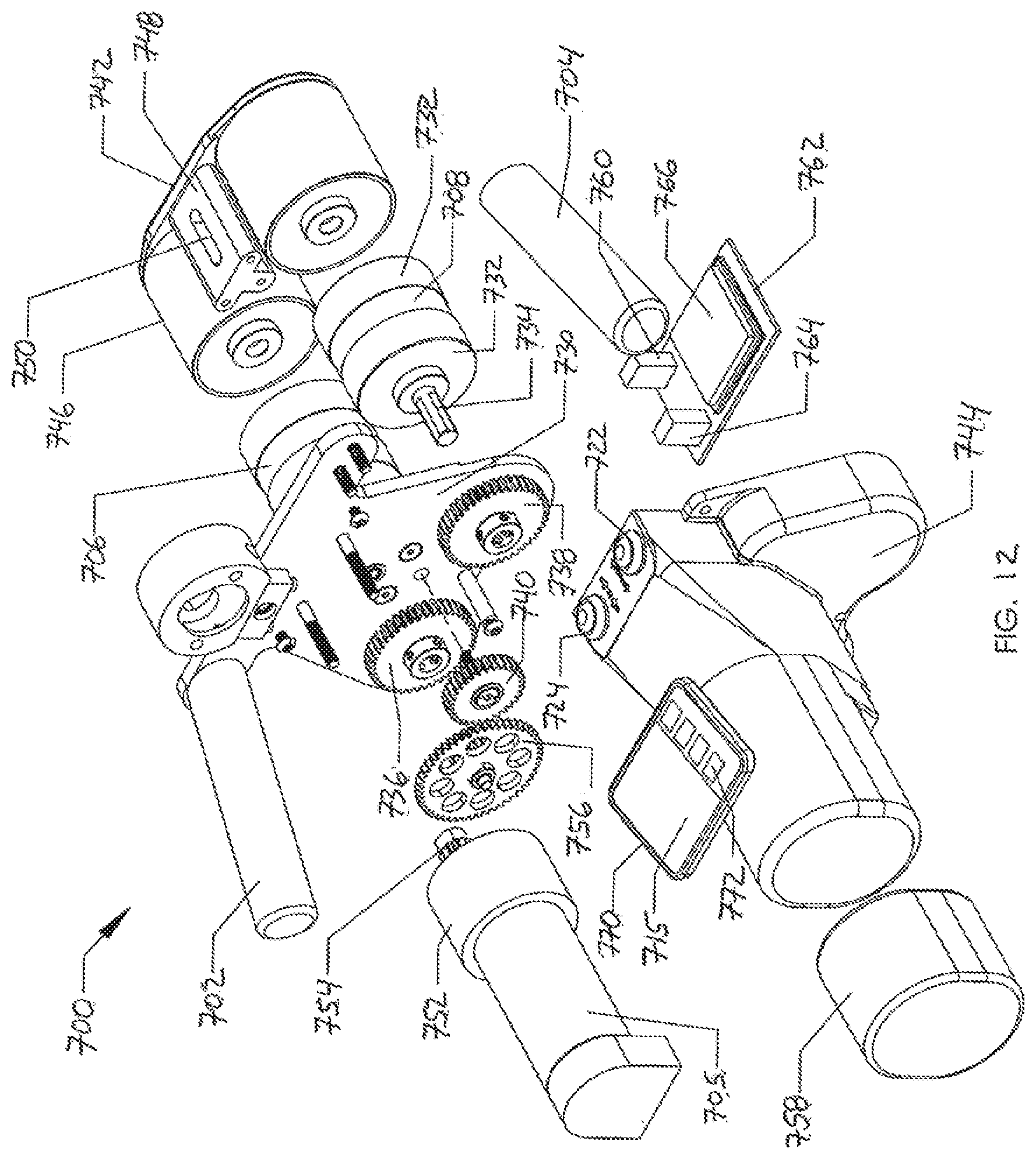
D00013
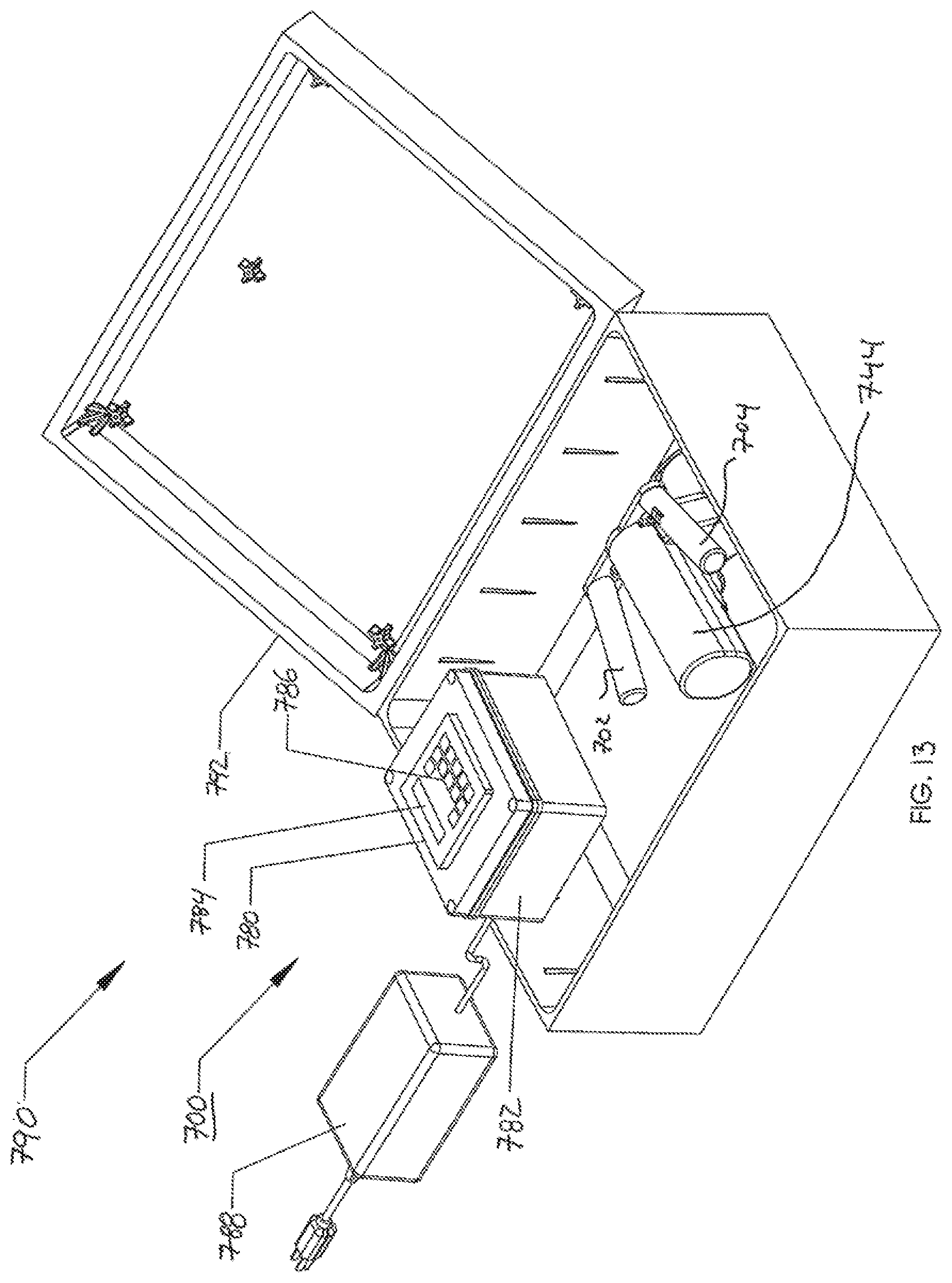
D00014
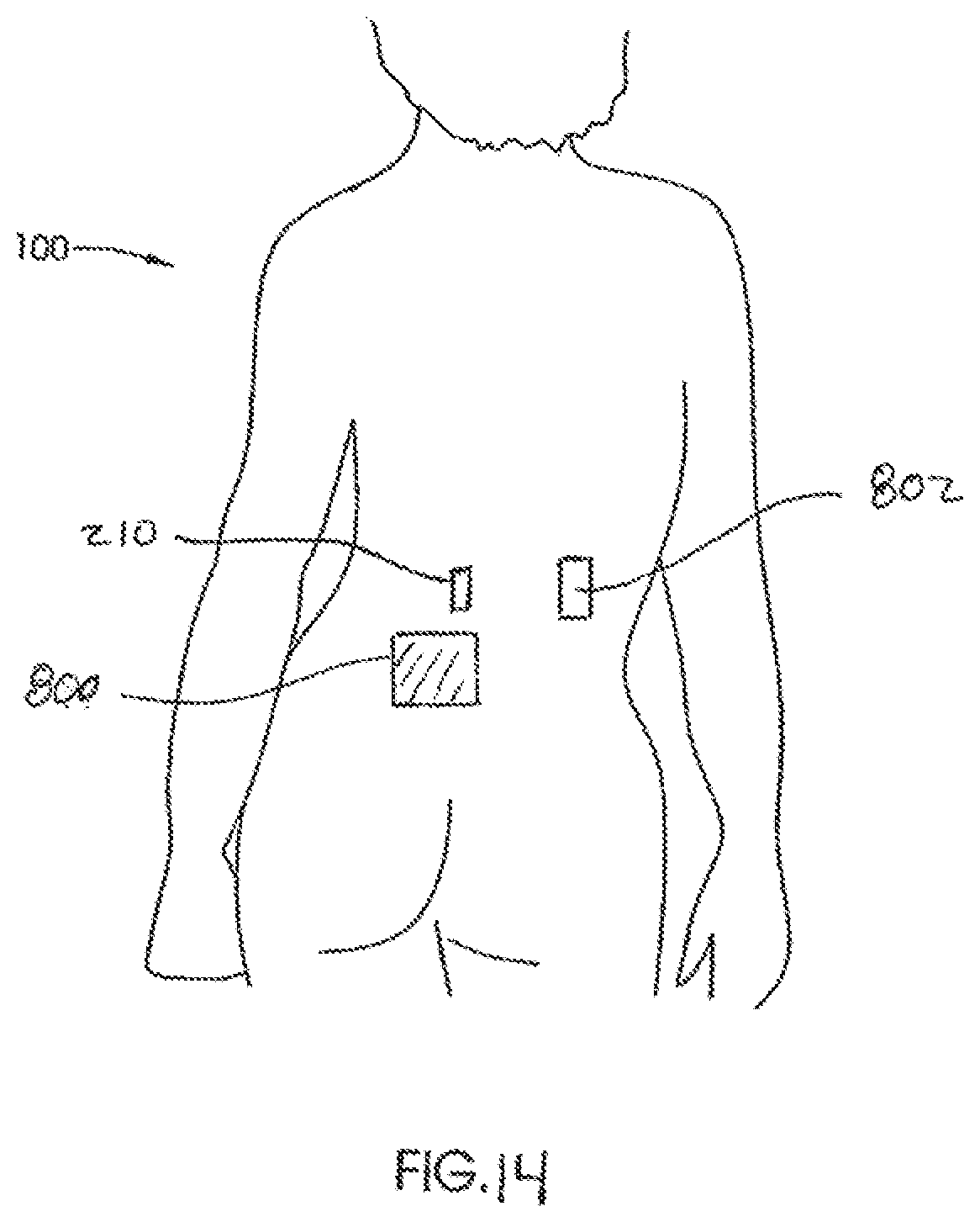
XML
uspto.report is an independent third-party trademark research tool that is not affiliated, endorsed, or sponsored by the United States Patent and Trademark Office (USPTO) or any other governmental organization. The information provided by uspto.report is based on publicly available data at the time of writing and is intended for informational purposes only.
While we strive to provide accurate and up-to-date information, we do not guarantee the accuracy, completeness, reliability, or suitability of the information displayed on this site. The use of this site is at your own risk. Any reliance you place on such information is therefore strictly at your own risk.
All official trademark data, including owner information, should be verified by visiting the official USPTO website at www.uspto.gov. This site is not intended to replace professional legal advice and should not be used as a substitute for consulting with a legal professional who is knowledgeable about trademark law.