Console assembly for vehicle interior
Anderson , et al.
U.S. patent number 10,717,390 [Application Number 15/890,953] was granted by the patent office on 2020-07-21 for console assembly for vehicle interior. This patent grant is currently assigned to Shanghai Yanfeng Jinqiao Automotive Trim Systems Co. Ltd.. The grantee listed for this patent is Shanghai Yanfeng Jinqiao Automotive Trim Systems Co. Ltd.. Invention is credited to Rick Alan Anderson, Dennis Jack VanHouten, Loren Ray Washburn.


View All Diagrams
| United States Patent | 10,717,390 |
| Anderson , et al. | July 21, 2020 |
Console assembly for vehicle interior
Abstract
A vehicle interior component may comprise a console assembly such as a floor console. The vehicle interior component may comprise a base providing a compartment; a cover movable between a closed position and open position; and a latch mechanism comprising an arm providing a latch feature to secure the cover to the base. The cover may comprise a latch feature; the arm may move between an elevated position for the latch feature of the arm to engage the latch feature of the cover to secure the cover to the base and a retracted position for the latch feature of the arm to disengage the latch feature of the cover to release the cover from the base. The vehicle interior component may comprise a mechanism to actuate movement of the cover to the open position. The latch mechanism may comprise a concealed magnetic latch.
| Inventors: | Anderson; Rick Alan (Grand Haven, MI), Washburn; Loren Ray (Hamilton, MI), VanHouten; Dennis Jack (Wyoming, MI) | ||||||||||
|---|---|---|---|---|---|---|---|---|---|---|---|
| Applicant: |
|
||||||||||
| Assignee: | Shanghai Yanfeng Jinqiao Automotive
Trim Systems Co. Ltd. (Novi, MI) |
||||||||||
| Family ID: | 60326184 | ||||||||||
| Appl. No.: | 15/890,953 | ||||||||||
| Filed: | February 7, 2018 |
Prior Publication Data
| Document Identifier | Publication Date | |
|---|---|---|
| US 20180162281 A1 | Jun 14, 2018 | |
Related U.S. Patent Documents
| Application Number | Filing Date | Patent Number | Issue Date | ||
|---|---|---|---|---|---|
| PCT/US2017/033149 | May 17, 2017 | ||||
| 62338413 | May 18, 2016 | ||||
| Current U.S. Class: | 1/1 |
| Current CPC Class: | B60R 7/04 (20130101); E05B 77/42 (20130101); B60N 2/793 (20180201); E05C 19/165 (20130101); E05B 83/32 (20130101); E05Y 2900/538 (20130101); B60R 2011/0007 (20130101) |
| Current International Class: | B60R 7/04 (20060101); E05C 19/16 (20060101); B60N 2/75 (20180101); E05B 77/42 (20140101); E05B 83/32 (20140101); B60R 11/00 (20060101) |
| Field of Search: | ;296/24.34,37.8 |
References Cited [Referenced By]
U.S. Patent Documents
| 71828 | December 1867 | Wells |
| 168560 | October 1875 | Drescher |
| 471634 | September 1901 | Cushing |
| 984204 | April 1906 | Erickson |
| 986237 | March 1911 | Spink et al. |
| 1111362 | September 1914 | Carrigan et al. |
| 1111386 | September 1914 | Hutton et al. |
| 1320444 | September 1914 | Buczynski et al. |
| 1664476 | April 1928 | Geib et al. |
| 2219186 | October 1940 | Hornfeck et al. |
| 2288688 | July 1942 | William et al. |
| 2342848 | February 1944 | Endter et al. |
| 2446336 | August 1948 | Mark et al. |
| 2468969 | May 1949 | Galey et al. |
| 2471634 | May 1949 | Mark et al. |
| 2475226 | May 1949 | Ellis |
| 2508305 | May 1950 | Teetor et al. |
| 2524924 | October 1950 | Vincent et al. |
| 2527924 | October 1950 | Thorsten et al. |
| 2565891 | August 1951 | Sherman et al. |
| 2584480 | August 1951 | Manting |
| 2586900 | February 1952 | Wayne et al. |
| 2648884 | August 1953 | Elston et al. |
| 2673111 | March 1954 | Teetor et al. |
| 2690349 | September 1954 | Teetor et al. |
| 2708284 | May 1955 | Conklin et al. |
| 2727772 | May 1955 | Hamilton |
| 2735740 | February 1956 | Soans |
| 2797655 | July 1957 | Morehouse et al. |
| 2889164 | June 1959 | Clark et al. |
| 2898138 | August 1959 | Noord et al. |
| 2913605 | August 1959 | Johnson |
| 2932545 | April 1960 | Foley et al. |
| 2970857 | February 1961 | Squire et al. |
| 3009725 | November 1961 | Koch et al. |
| 3066964 | December 1962 | Georges et al. |
| 3100350 | December 1962 | Brown |
| 3111834 | November 1963 | Ronald et al. |
| 3151902 | October 1964 | Ahlgren et al. |
| 3184654 | May 1965 | Bey et al. |
| 3204154 | August 1965 | Crandell et al. |
| 3264424 | August 1966 | Max et al. |
| 3288511 | November 1966 | Tavano et al. |
| 3309696 | March 1967 | Alster et al. |
| 3332713 | July 1967 | De et al. |
| 3334936 | August 1967 | Maarten et al. |
| 3372443 | March 1968 | Daddona et al. |
| 3376615 | April 1968 | Heckman et al. |
| 3416336 | December 1968 | Ronald et al. |
| 3468576 | September 1969 | Beyer et al. |
| 3468579 | September 1969 | Tabor |
| 3516701 | September 1969 | Graham |
| 3578370 | May 1971 | Greytok |
| 3596858 | August 1971 | Curtis |
| 3596958 | August 1971 | Bowerman et al. |
| 3611219 | October 1971 | Iwami et al. |
| 3620560 | November 1971 | Peters et al. |
| 3635511 | January 1972 | Waller et al. |
| 3647165 | March 1972 | Whitla et al. |
| 3658370 | April 1972 | Wang et al. |
| 3744833 | July 1973 | Berducone |
| 3782147 | January 1974 | Hallmann |
| 3790197 | February 1974 | Parker |
| 3822906 | July 1974 | Gaines |
| 3831986 | August 1974 | Kobayashi |
| 3860277 | January 1975 | Wang |
| 3934909 | January 1976 | Van Natter |
| 3992689 | November 1976 | Kaplow |
| 4062548 | December 1977 | Kagata |
| 4099755 | July 1978 | Anderson |
| 4155576 | May 1979 | Kennon |
| 4195236 | March 1980 | Kalinichenko et al. |
| 4222021 | September 1980 | Bunker, Jr. |
| 4256340 | March 1981 | Dunchock |
| 4262830 | April 1981 | Haves |
| 4265002 | May 1981 | Hosken |
| 4268076 | May 1981 | Itoi |
| 4270781 | June 1981 | Nishimura |
| 4301623 | November 1981 | Demukai |
| 4355837 | October 1982 | Shimizu et al. |
| 4363403 | December 1982 | Raucci, Jr. et al. |
| 4364019 | December 1982 | Hutter |
| 4380162 | April 1983 | Woolfson |
| 4397166 | August 1983 | Paar |
| 4428607 | January 1984 | Levine |
| 4518180 | May 1985 | Kleefeldt et al. |
| 4518181 | May 1985 | Yamada |
| 4569544 | February 1986 | Escaravage |
| 4597598 | July 1986 | Bascou |
| 4660871 | April 1987 | Arakawa et al. |
| 4669766 | June 1987 | Hanchett, Jr. et al. |
| 4686841 | August 1987 | Prunbauer et al. |
| 4696550 | September 1987 | Shionoya |
| 4697903 | October 1987 | Koda et al. |
| 4703586 | November 1987 | Smith et al. |
| 4732432 | March 1988 | Keil et al. |
| 4763936 | August 1988 | Rogakos et al. |
| 4766276 | August 1988 | Clark et al. |
| 4796932 | January 1989 | Tame |
| 4815304 | March 1989 | Kesselman |
| 4840411 | June 1989 | Sowersby |
| 4848809 | July 1989 | Escaravage |
| 4861089 | August 1989 | Compeau et al. |
| 4867496 | September 1989 | Thomas |
| 4875823 | October 1989 | Fuse et al. |
| 4893478 | January 1990 | Kruck et al. |
| 4895640 | January 1990 | Jackson |
| 4901261 | February 1990 | Fuhs |
| 4919464 | April 1990 | Richards |
| 4927196 | May 1990 | Girard et al. |
| 4940207 | July 1990 | Katsuyama |
| 4958508 | September 1990 | Lin |
| 4964661 | October 1990 | Cadwell et al. |
| 4973020 | November 1990 | Canadas |
| 4978478 | December 1990 | Vonderau et al. |
| 4982303 | January 1991 | Krenz |
| 5033789 | July 1991 | Hayashi et al. |
| 5046340 | September 1991 | Weinerman et al. |
| 5067625 | November 1991 | Numata |
| 5076623 | December 1991 | Richards |
| 5116099 | May 1992 | Kwasnik et al. |
| 5128829 | July 1992 | Loew |
| 5175672 | December 1992 | Conner et al. |
| 5180198 | January 1993 | Nakamura et al. |
| 5188405 | February 1993 | Maccaferri |
| 5210906 | May 1993 | Aihara et al. |
| 5222775 | June 1993 | Kato |
| 5253142 | October 1993 | Weng |
| 5305623 | April 1994 | Kello |
| 5309680 | May 1994 | Kiel |
| 5351812 | October 1994 | Eagon |
| 5367891 | November 1994 | Furuyama |
| 5389920 | February 1995 | DeLand et al. |
| 5406340 | April 1995 | Hoff |
| 5409275 | April 1995 | Yoshida et al. |
| 5411302 | May 1995 | Shimada |
| 5413391 | May 1995 | Clavin et al. |
| 5429400 | July 1995 | Kawaguchi et al. |
| 5466166 | November 1995 | Law et al. |
| 5485733 | January 1996 | Hoffman |
| 5488522 | January 1996 | Peace et al. |
| 5497296 | March 1996 | Satou et al. |
| 5498040 | March 1996 | Silye |
| 5510953 | April 1996 | Merkel |
| 5515237 | May 1996 | Ogami et al. |
| 5518282 | May 1996 | Sawada |
| 5520313 | May 1996 | Toshihide |
| 5544925 | August 1996 | Ikeda |
| 5555157 | September 1996 | Moller et al. |
| 5570915 | November 1996 | Asadurian |
| 5574625 | November 1996 | Ohgami et al. |
| 5576929 | November 1996 | Uchiyama et al. |
| 5580107 | December 1996 | Howell |
| 5612831 | March 1997 | Gallo et al. |
| 5620226 | April 1997 | Sautter, Jr. |
| 5631618 | May 1997 | Trumper et al. |
| 5632515 | May 1997 | Dowling |
| 5642636 | July 1997 | Mitsui |
| 5647562 | July 1997 | Lumbis et al. |
| 5647652 | July 1997 | Zalewski et al. |
| 5706332 | January 1998 | Nagai |
| 5715815 | February 1998 | Lorenzen et al. |
| 5721669 | February 1998 | Becker et al. |
| 5737185 | April 1998 | Morrison et al. |
| 5740012 | April 1998 | Choi |
| 5765884 | June 1998 | Armbruster |
| 5782512 | July 1998 | Cargnoni |
| 5791442 | August 1998 | Arnold |
| 5809520 | September 1998 | Edwards et al. |
| 5812370 | September 1998 | Moore et al. |
| 5816080 | October 1998 | Jeziorowski |
| 5818182 | October 1998 | Viswanadham et al. |
| 5825616 | October 1998 | Howell et al. |
| 5841631 | November 1998 | Shin et al. |
| 5893478 | April 1999 | Maruoka |
| 5927772 | July 1999 | Antonucci et al. |
| 5941104 | August 1999 | Sadler |
| 5959833 | September 1999 | Youens |
| 5969941 | October 1999 | Cho |
| 5975661 | November 1999 | Jeziorowski et al. |
| 5984383 | November 1999 | Parikh et al. |
| 5996831 | December 1999 | Teok |
| 6010344 | January 2000 | Muramatsu et al. |
| 6048006 | April 2000 | Antonucci et al. |
| 6049453 | April 2000 | Hulsebosch |
| 6053546 | April 2000 | Frolov |
| 6062623 | May 2000 | Lemmen |
| 6068307 | May 2000 | Murphy |
| 6076868 | June 2000 | Roger, Jr. et al. |
| 6113161 | September 2000 | Jung et al. |
| 6115239 | September 2000 | Kim |
| 6129395 | October 2000 | Schlesener et al. |
| 6139073 | October 2000 | Heffner et al. |
| 6151486 | November 2000 | Holshouser et al. |
| 6176528 | January 2001 | Taga |
| 6256194 | July 2001 | Choi et al. |
| 6264273 | July 2001 | Waters, Sr. |
| 6267420 | July 2001 | Miyagawa |
| 6324052 | November 2001 | Azima et al. |
| 6327879 | December 2001 | Malsom |
| 6366440 | April 2002 | Kung |
| 6370376 | April 2002 | Sheath |
| 6386599 | May 2002 | Chevalier |
| 6460902 | October 2002 | Kyle |
| 6463773 | October 2002 | Dimig |
| 6467903 | October 2002 | Back |
| 6471260 | October 2002 | Weinerman et al. |
| 6474120 | November 2002 | Wadsworth et al. |
| 6480377 | November 2002 | Genest et al. |
| 6510048 | January 2003 | Rubenson et al. |
| 6542372 | April 2003 | Paquin et al. |
| 6588811 | July 2003 | Ferguson |
| 6616205 | September 2003 | Bruhnke et al. |
| 6640398 | November 2003 | Hoffman |
| 6653919 | November 2003 | Shih-Chung et al. |
| 6659516 | December 2003 | Wang et al. |
| 6684904 | February 2004 | Ito |
| 6705140 | March 2004 | Dimig et al. |
| 6715815 | April 2004 | Toppani |
| 6736438 | May 2004 | Wieclawski |
| 6747537 | June 2004 | Mosteller |
| 6765330 | July 2004 | Baur |
| 6832100 | December 2004 | Hsieh |
| 6842332 | January 2005 | Rubenson et al. |
| 6883680 | April 2005 | Hirose |
| D506120 | June 2005 | Straka, Jr. et al. |
| 6929291 | August 2005 | Chen |
| 6971147 | December 2005 | Halstead |
| 7042713 | May 2006 | Nicolosi |
| 7082035 | July 2006 | Kim |
| 7092070 | August 2006 | McCullough et al. |
| 7250207 | July 2007 | Heal et al. |
| 7259970 | August 2007 | Nakayabu |
| 7261331 | August 2007 | Lin |
| 7265470 | September 2007 | Paden et al. |
| 7267378 | September 2007 | Drumm |
| 7286369 | October 2007 | Yaor |
| 7332990 | February 2008 | Lo et al. |
| 7390035 | June 2008 | Karcz et al. |
| 7486165 | February 2009 | Ligtenberg et al. |
| 7591395 | September 2009 | Hamaguchi |
| 7637543 | December 2009 | Ferguson |
| 7724113 | May 2010 | Fullerton et al. |
| 7748762 | July 2010 | Mayne, Jr. |
| 7766407 | August 2010 | Nakaya |
| 7770953 | August 2010 | Koarai |
| 7775567 | August 2010 | Ligtenberg et al. |
| 7817002 | October 2010 | Fullerton et al. |
| 7889036 | February 2011 | Fiedler |
| 7931313 | April 2011 | Carabalona |
| 8004393 | August 2011 | Haber |
| 8052181 | November 2011 | Nishida |
| 8172299 | May 2012 | Lota |
| 8186734 | May 2012 | Nakaya |
| 8256814 | September 2012 | Thorsell et al. |
| 8373526 | February 2013 | Fullerton et al. |
| 8395467 | March 2013 | Fullerton et al. |
| 8403382 | March 2013 | Della-Santa |
| 8458863 | June 2013 | Hunts |
| 8482394 | July 2013 | Nass et al. |
| 8505989 | August 2013 | Wells |
| 8528950 | September 2013 | Organek et al. |
| 8540292 | September 2013 | Ferguson |
| 8672368 | March 2014 | Grosdemouge |
| 8794473 | August 2014 | Kang |
| 8801054 | August 2014 | Ligtenberg et al. |
| 8816636 | August 2014 | Shinde et al. |
| 8864188 | October 2014 | Redgrave |
| 9004550 | April 2015 | Carabalona et al. |
| 9257245 | February 2016 | Sun et al. |
| 9415710 | August 2016 | Simon |
| 9476228 | October 2016 | Karcz et al. |
| 9573529 | February 2017 | Hipshier et al. |
| 2001/0024039 | September 2001 | Lippoldt et al. |
| 2001/0035654 | November 2001 | Cetnar et al. |
| 2001/0045750 | November 2001 | Ji et al. |
| 2002/0017791 | February 2002 | Ji et al. |
| 2002/0043608 | April 2002 | Nakata et al. |
| 2002/0084666 | July 2002 | Toppani |
| 2002/0105400 | August 2002 | Underwood et al. |
| 2002/0105401 | August 2002 | Shih-Chung et al. |
| 2002/0112322 | August 2002 | Hoffman |
| 2002/0116794 | August 2002 | Hoffman |
| 2002/0121784 | September 2002 | Chevalier |
| 2002/0130128 | September 2002 | Berglund |
| 2002/0147026 | October 2002 | Hsieh |
| 2002/0153376 | October 2002 | Seidler |
| 2002/0158475 | October 2002 | Rice et al. |
| 2002/0167175 | November 2002 | Weyerstall et al. |
| 2003/0025339 | February 2003 | Vitry et al. |
| 2003/0035297 | February 2003 | Bingle et al. |
| 2003/0047955 | March 2003 | Bruhnke et al. |
| 2003/0053855 | March 2003 | Baur |
| 2003/0094024 | May 2003 | Dimig |
| 2003/0132234 | July 2003 | Hirose |
| 2003/0177796 | September 2003 | Dimig |
| 2003/0193199 | October 2003 | Talukdar et al. |
| 2004/0070214 | April 2004 | Queveau et al. |
| 2004/0113433 | June 2004 | Marzolf et al. |
| 2004/0118171 | June 2004 | Vitry et al. |
| 2004/0174670 | September 2004 | Huang et al. |
| 2004/0197713 | October 2004 | Ohfuji et al. |
| 2004/0222645 | November 2004 | Pirone et al. |
| 2005/0000327 | January 2005 | Monroig et al. |
| 2005/0018393 | January 2005 | Kuo et al. |
| 2005/0023847 | February 2005 | Van Damme et al. |
| 2005/0044904 | March 2005 | Horngren et al. |
| 2005/0047054 | March 2005 | Klees |
| 2005/0059443 | March 2005 | Pan et al. |
| 2005/0062296 | March 2005 | Lyon |
| 2005/0067840 | March 2005 | Koveal et al. |
| 2005/0083644 | April 2005 | Song |
| 2005/0097711 | May 2005 | Halstead |
| 2005/0115289 | June 2005 | Talukdar et al. |
| 2005/0128695 | June 2005 | Han |
| 2005/0133507 | June 2005 | Tanaka |
| 2005/0142936 | June 2005 | Sung et al. |
| 2005/0151381 | July 2005 | Durbin |
| 2005/0160777 | July 2005 | Baechle et al. |
| 2005/0167992 | August 2005 | Lo et al. |
| 2005/0183940 | August 2005 | Ichimaru |
| 2005/0200137 | September 2005 | Nelsen et al. |
| 2005/0236848 | October 2005 | Kim |
| 2006/0006674 | January 2006 | Kang et al. |
| 2006/0023408 | February 2006 | Schlesener et al. |
| 2006/0037965 | February 2006 | Hamaguchi |
| 2006/0038415 | February 2006 | Liu et al. |
| 2006/0049645 | March 2006 | Drumm |
| 2006/0071746 | April 2006 | Lylyharju |
| 2006/0097532 | May 2006 | Adams et al. |
| 2006/0108816 | May 2006 | Radu et al. |
| 2006/0175842 | August 2006 | Saitoh et al. |
| 2006/0290144 | December 2006 | Nakaya |
| 2007/0007775 | January 2007 | Gallas et al. |
| 2007/0133156 | June 2007 | Ligtenberg et al. |
| 2007/0138806 | June 2007 | Ligtenberg et al. |
| 2007/0159033 | July 2007 | McBroom et al. |
| 2007/0216173 | September 2007 | Vitry |
| 2007/0257496 | November 2007 | Spurr et al. |
| 2008/0136197 | June 2008 | Lin |
| 2008/0150341 | June 2008 | Salewski |
| 2008/0174127 | July 2008 | Kim et al. |
| 2008/0191494 | August 2008 | Carabalona et al. |
| 2008/0231060 | September 2008 | Carabalona et al. |
| 2008/0265588 | October 2008 | Carabalona |
| 2008/0309032 | December 2008 | Keane et al. |
| 2009/0021333 | January 2009 | Fiedler |
| 2009/0066103 | March 2009 | Koarai |
| 2009/0072565 | March 2009 | Mayne, Jr. |
| 2009/0079205 | March 2009 | Nishida |
| 2009/0174990 | July 2009 | Ligtenberg et al. |
| 2009/0218842 | September 2009 | Muller |
| 2009/0230699 | September 2009 | Carabalona |
| 2010/0032403 | February 2010 | Hajichristou et al. |
| 2010/0083580 | April 2010 | Lota |
| 2010/0171578 | July 2010 | Fiedler |
| 2010/0188177 | July 2010 | Inage |
| 2010/0254111 | October 2010 | Ligtenberg et al. |
| 2010/0283269 | November 2010 | Fiedler |
| 2010/0287741 | November 2010 | Fiedler |
| 2011/0031766 | February 2011 | Huang et al. |
| 2011/0132907 | June 2011 | Hajichristou et al. |
| 2011/0167595 | July 2011 | Fiedler |
| 2011/0215605 | September 2011 | Spitler et al. |
| 2011/0215686 | September 2011 | Yang |
| 2012/0319422 | December 2012 | Kang |
| 2013/0094142 | April 2013 | Ligtenbert et al. |
| 2014/0047677 | February 2014 | Trinh |
| 2014/0062103 | March 2014 | Gillis |
| 2014/0145453 | May 2014 | Zhang et al. |
| 2015/0054608 | February 2015 | Sun et al. |
| 2015/0137553 | May 2015 | Iman |
| 2015/0343956 | December 2015 | Hipshier et al. |
| 2016/0159289 | June 2016 | Gaudig |
| 2016/0304031 | October 2016 | Hipshier et al. |
| 512602 | Sep 2013 | AT | |||
| 669664 | Dec 1965 | BE | |||
| 103836324 | Jun 2014 | CN | |||
| 204172791 | Feb 2015 | CN | |||
| 204184264 | Mar 2015 | CN | |||
| 105105490 | Dec 2015 | CN | |||
| 105682503 | Jun 2016 | CN | |||
| 145325 | Nov 1903 | DE | |||
| 479949 | Jul 1929 | DE | |||
| 940451 | Mar 1956 | DE | |||
| 1157109 | Nov 1963 | DE | |||
| 1916694 | May 1965 | DE | |||
| 1968971 | Sep 1967 | DE | |||
| 1286933 | Jan 1969 | DE | |||
| 1903446 | Sep 1969 | DE | |||
| 1553540 | Oct 1969 | DE | |||
| 7121004 | Sep 1971 | DE | |||
| 2112425 | Sep 1972 | DE | |||
| 2323058 | Nov 1974 | DE | |||
| 2455520 | May 1976 | DE | |||
| 2918782 | Jan 1980 | DE | |||
| 2921613 | Sep 1980 | DE | |||
| 8028776 | Jul 1981 | DE | |||
| 3521979 | Jan 1987 | DE | |||
| 8902181 | May 1989 | DE | |||
| 3804176 | Aug 1989 | DE | |||
| 4130847 | Mar 1993 | DE | |||
| 4337426 | May 1995 | DE | |||
| 69206404 | Jun 1996 | DE | |||
| 29622577 | Apr 1997 | DE | |||
| 19642071 | Apr 1998 | DE | |||
| 19829958 | Jan 2000 | DE | |||
| 19840620 | Apr 2000 | DE | |||
| 19911792 | Sep 2000 | DE | |||
| 19943041 | Mar 2001 | DE | |||
| 19961893 | Jul 2001 | DE | |||
| 19953898 | Aug 2001 | DE | |||
| 10009291 | Sep 2001 | DE | |||
| 10104010 | Aug 2002 | DE | |||
| 20215067 | Jan 2003 | DE | |||
| 19738181 | Apr 2003 | DE | |||
| 10213772 | Oct 2003 | DE | |||
| 10216225 | Oct 2003 | DE | |||
| 10247453 | Apr 2004 | DE | |||
| 10312269 | Sep 2004 | DE | |||
| 10325105 | Dec 2004 | DE | |||
| 10339363 | Mar 2005 | DE | |||
| 202004019166 | Mar 2005 | DE | |||
| 102004015718 | May 2005 | DE | |||
| 202004001958 | Jun 2005 | DE | |||
| 102005007042 | Nov 2005 | DE | |||
| 102004049024 | Apr 2006 | DE | |||
| 102004054028 | May 2006 | DE | |||
| 102004056197 | May 2006 | DE | |||
| 102005011158 | Sep 2006 | DE | |||
| 102007047537 | Apr 2009 | DE | |||
| 102008050866 | Apr 2010 | DE | |||
| 102008057436 | May 2010 | DE | |||
| 102009006206 | Jul 2010 | DE | |||
| 102009037036 | Feb 2011 | DE | |||
| 102009059050 | Jun 2011 | DE | |||
| 102011012434 | Aug 2012 | DE | |||
| 102011103554 | Dec 2012 | DE | |||
| 102009007723 | Jan 2013 | DE | |||
| 102013014155 | Apr 2014 | DE | |||
| 102010039821 | May 2014 | DE | |||
| 202016100610 | Feb 2016 | DE | |||
| 102015105977 | May 2016 | DE | |||
| 102015009585 | Jan 2017 | DE | |||
| 102015113811 | Feb 2017 | DE | |||
| 0099223 | Jan 1984 | EP | |||
| 0367000 | May 1990 | EP | |||
| 0490468 | Jun 1992 | EP | |||
| 0564441 | Oct 1993 | EP | |||
| 0575962 | Dec 1993 | EP | |||
| 0825628 | Feb 1998 | EP | |||
| 0559267 | Apr 1999 | EP | |||
| 1050649 | Nov 2000 | EP | |||
| 1411193 | Apr 2004 | EP | |||
| 1473511 | Nov 2004 | EP | |||
| 1574147 | Sep 2005 | EP | |||
| 1638206 | Mar 2006 | EP | |||
| 1427648 | Jul 2006 | EP | |||
| 1764266 | Mar 2007 | EP | |||
| 1916365 | Apr 2008 | EP | |||
| 1929896 | Jun 2008 | EP | |||
| 2027791 | Feb 2009 | EP | |||
| 2045423 | Apr 2009 | EP | |||
| 1329581 | Jan 2011 | EP | |||
| 2284341 | Feb 2011 | EP | |||
| 2314810 | Apr 2011 | EP | |||
| 2527573 | Nov 2012 | EP | |||
| 1846904 | Oct 2015 | EP | |||
| 1880073 | Jun 2016 | EP | |||
| 669664 | Nov 1929 | FR | |||
| 1238808 | Aug 1960 | FR | |||
| 2724609 | Mar 1996 | FR | |||
| 2852794 | Oct 2004 | FR | |||
| 2862948 | Jun 2005 | FR | |||
| 2867361 | Sep 2005 | FR | |||
| 2885380 | Nov 2006 | FR | |||
| 2919584 | Feb 2009 | FR | |||
| 2931642 | Dec 2009 | FR | |||
| 2961763 | Dec 2011 | FR | |||
| 2973665 | Oct 2012 | FR | |||
| 3014927 | Jun 2015 | FR | |||
| 573454 | Nov 1945 | GB | |||
| 629903 | Sep 1949 | GB | |||
| 1094757 | Dec 1967 | GB | |||
| 1207641 | Oct 1970 | GB | |||
| 2236139 | Mar 1991 | GB | |||
| 2264975 | Sep 1993 | GB | |||
| 2397616 | Jul 2004 | GB | |||
| 2460775 | Dec 2009 | GB | |||
| S56148471 | Nov 1981 | JP | |||
| S5829759 | Feb 1983 | JP | |||
| S5923596 | Feb 1984 | JP | |||
| S6095336 | Jun 1985 | JP | |||
| S63143668 | Sep 1988 | JP | |||
| H0381242 | Aug 1991 | JP | |||
| H04185880 | Jul 1992 | JP | |||
| H05340149 | Dec 1993 | JP | |||
| H0816423 | Feb 1996 | JP | |||
| H10165208 | Jun 1998 | JP | |||
| H11107608 | Apr 1999 | JP | |||
| H11252232 | Sep 1999 | JP | |||
| 3002189 | Jan 2000 | JP | |||
| 2000142243 | May 2000 | JP | |||
| 2000325116 | Nov 2000 | JP | |||
| 2001219012 | Aug 2001 | JP | |||
| 2002219012 | Aug 2002 | JP | |||
| 2003148029 | May 2003 | JP | |||
| 2007261435 | Oct 2007 | JP | |||
| 2007530184 | Nov 2007 | JP | |||
| 2011107608 | Jun 2011 | JP | |||
| 20030086387 | Nov 2003 | KR | |||
| 20100093757 | Aug 2010 | KR | |||
| 1036087 | Apr 2010 | NL | |||
| 118893 | Dec 2003 | RO | |||
| 2002004773 | Jan 2002 | WO | |||
| 2003018423 | Mar 2003 | WO | |||
| 2003085833 | Oct 2003 | WO | |||
| 2004083578 | Sep 2004 | WO | |||
| 2005094625 | Oct 2005 | WO | |||
| 2005096264 | Oct 2005 | WO | |||
| 2006040531 | Apr 2006 | WO | |||
| 2006088775 | Aug 2006 | WO | |||
| 2006094491 | Sep 2006 | WO | |||
| 2006122151 | Nov 2006 | WO | |||
| 2007129484 | Nov 2007 | WO | |||
| 2008006357 | Jan 2008 | WO | |||
| 2010037442 | Apr 2010 | WO | |||
| 2011072427 | Jun 2011 | WO | |||
| 2012113550 | Aug 2012 | WO | |||
| 2015025321 | Feb 2015 | WO | |||
| 2015092249 | Jun 2015 | WO | |||
| 2016094844 | Jun 2016 | WO | |||
Other References
|
Extended European Search Report from the European Patent Office for EP Patent Application No. 17800110.3 dated Sep. 24, 2019 (in English) (8 pages). cited by applicant . Notification of Transmittal of International Search Report and Written Opinion of the International Searching Authority (PCT/ISA/220) with International Search Report (PCT/ISA/210) and Written Opinion of the International Searching Authority (PCT/ISA/237) for International Application No. PCT/US2017/033149 dated Aug. 16, 2017 (15 pages). cited by applicant . Non-Final Office Action from the United States Patent and Trademark Office for U.S. Appl. No. 15/890,980 dated Jan. 2, 2020 (in English) (13 pages). cited by applicant. |
Primary Examiner: Daniels; Jason S
Parent Case Text
CROSS-REFERENCE TO RELATED APPLICATIONS
The present application is a continuation of International/PCT Patent Application No. PCT/US2017/033149 titled "CONSOLE ASSEMBLY FOR VEHICLE INTERIOR" filed May 17, 2017, which claims the benefit of U.S. Provisional Patent Application No. 62/338,413 titled "CONSOLE FOR VEHICLE INTERIOR" filed May 18, 2016.
The present application is related to and incorporates by reference in full the following applications: (a) U.S. Provisional Patent Application No. 62/338,413 titled "CONSOLE FOR VEHICLE INTERIOR" filed May 18, 2016; (b) International/PCT Patent Application No. PCT/US2017/033149 titled "CONSOLE ASSEMBLY FOR VEHICLE INTERIOR" filed May 17, 2017; (c) U.S. patent application Ser. No. 15/890,980 titled "CONSOLE ASSEMBLY FOR VEHICLE INTERIOR" filed Feb. 7, 2018.
Claims
The invention claimed is:
1. A vehicle interior component configured to be operated by application of an external force from an occupant comprising: (a) a base providing a compartment; (b) a cover movable relative to the base from a closed position to an open position; and (c) a latch mechanism configured to secure the cover to the base; wherein the cover comprises a latch feature; wherein the latch mechanism comprises an arm providing a latch feature; wherein the cover is configured to actuate the latch mechanism; wherein the arm is configured for movement relative to the base from an elevated position for the latch feature of the arm to engage the latch feature of the cover to secure the cover to the base to a retracted position for the latch feature of the arm to disengage the latch feature of the cover to release the cover from the base in response to application of external force on the cover; and wherein the base comprises a structure comprising a first sidewall and a second sidewall to define the compartment and the latch mechanism is installed at the first sidewall.
2. The component of claim 1 wherein the arm rotates relative to the base between a stop at the retracted position and a stop at the elevated position.
3. The component of claim 1 wherein the base comprises an opening provided in the first sidewall of the base or the second sidewall of the base; wherein the arm is configured to extend through the opening of the base to engage the cover to secure the cover to the base.
4. The component of claim 3 wherein the arm projects at least partially through the opening when in the elevated position to present the latch feature of the arm to engage the latch feature of the cover; wherein the arm retracts at least partially into the opening when in the retracted position.
5. The component of claim 1 wherein the arm is pivotally coupled to the base.
6. The component of claim 1 wherein at least one of (a) the latch feature of the arm (b) the latch feature of the cover comprises at least one magnet.
7. The component of claim 1 wherein a magnet installed in the arm engages a magnet installed in the cover when the cover is in the closed position.
8. The component of claim 1 wherein the arm comprises a counterweight.
9. The component of claim 8 wherein the counterweight is configured for at least one of: (a) to facilitate movement of the cover to the open position; (b) to maintain the cover in the closed position.
10. A vehicle interior component configured to be operated by application of an external force from an occupant comprising: (a) a base providing a compartment; (b) a cover movable relative to the base from a closed position to an open position; and (c) a latch mechanism configured to secure the cover to the base; wherein the cover comprises a latch feature; wherein the latch mechanism comprises an arm providing a latch feature; wherein the cover is configured to actuate the latch mechanism; wherein the arm is configured for movement relative to the base from an elevated position for the latch feature of the arm to engage the latch feature of the cover to secure the cover to the base to a retracted position for the latch feature of the arm to disengage the latch feature of the cover to release the cover from the base in response to rotation of the cover; and wherein the latch mechanism is configured to retain the arm in the retracted position.
11. The component of claim 10 further comprising a latch to retain the arm in the retracted position.
12. The component of claim 10 wherein the base comprises an opening provided in a sidewall of the base; wherein the arm is configured to extend through the opening of the base to engage the cover to secure the cover to the base.
13. The component of claim 12 wherein the arm is configured to retract at least partially into the sidewall of the base when the arm is in the retracted position.
14. The component of claim 10 wherein the arm comprises a magnet; wherein the cover comprises a magnet; and wherein the magnet of the arm engages the magnet of the cover when the cover is in the closed position.
15. The component of claim 10 wherein the arm comprises a counterweight; wherein the counterweight is configured for at least one of: (a) to facilitate movement of the cover to the open position; (b) to maintain the cover in the closed position.
16. A vehicle interior component configured to be operated by application of an external force from an occupant comprising: (a) a base providing a compartment; (b) a cover movable relative to the base from a closed position to an open position; and (c) a latch mechanism configured to secure the cover to the base; wherein the cover comprises a latch feature; wherein the latch mechanism comprises an arm providing a latch feature; wherein the cover is configured to actuate the latch mechanism; wherein the cover is configured to move the arm relative to the base from an elevated position for the latch feature of the arm to engage the latch feature of the cover to secure the cover to the base to a retracted position for the latch feature of the arm to disengage the latch feature of the cover to release the cover from the base in response to application of external force on the cover; wherein the latch feature of the cover comprises at least one magnet and the latch feature of the arm comprises at least one magnet; wherein the latch feature of the cover engages the latch feature of the arm at an interface; and wherein the interface comprises a housing for the at least one magnet of the latch feature of the cover and a housing for the at least one magnet of the latch feature of the arm.
17. The component of claim 16 wherein the cover is secured to the base by contact of the housing for the at least one magnet of the cover and the housing for the at least one magnet of the arm.
18. The component of claim 16 wherein the base comprises an opening provided in a sidewall of the base; wherein the arm is configured to extend through the opening of the base to engage the cover to secure the cover to the base.
19. The component of claim 18 wherein the arm is configured to retract at least partially into the sidewall of the base when the arm is in the retracted position.
20. The component of claim 16 wherein the arm comprises a counterweight; wherein the counterweight is configured for at least one of: (a) to facilitate movement of the cover to the open position; (b) to maintain the cover in the closed position.
Description
FIELD
The present invention relates to a console assembly for a vehicle interior.
BACKGROUND
It is well known to provide in a vehicle interior a console assembly comprising a base with a compartment and a cover movable relative to the base to facilitate access to the compartment.
It would be advantageous to provide an improved console assembly for a vehicle interior configured for improved functionality and operation comprising features (and combinations of features) as shown and described in the present application including features relating to a cover arrangement, a latch mechanism for the cover and a mechanism to actuate the cover.
SUMMARY
The present invention relates to a vehicle interior component configured to be operated by application of an external force from an occupant comprising: (a) a base providing a compartment; (b) a cover movable relative to the base from a closed position to an open position; and (c) a latch mechanism comprising an arm providing a latch feature configured to secure the cover to the base. The cover may comprise a latch feature; the arm may be configured for movement relative to the base between (1) an elevated position for the latch feature of the arm to engage the latch feature of the cover to secure the cover to the base and (2) a retracted position for the latch feature of the arm to disengage the latch feature of the cover to release the cover from the base. The arm may be pivotally coupled to the base. The latch feature of the arm may comprise at least one magnet. The latch feature of the arm may comprise an element of a material configured to be retained by at least one magnet; and the latch feature of the cover may comprise at least one magnet. A magnet of the arm may be installed in the arm and a magnet of the cover may be installed in the cover so that the magnet of the arm engages the magnet of the cover when the cover is in the closed position. The arm may be configured to rotate relative to the base between a stop at the retracted position and a stop at the elevated position. The latch mechanism may comprise a spring configured to retain the arm in the elevated position. The latch mechanism may comprise a push-push latch to retain the arm in the retracted position. The base may comprise an opening; the arm may be configured to extend through the opening of the base to engage the cover to secure the cover to the base. The opening may comprise a slot; the slot may be provided in a sidewall of the base. The arm may project at least partially through the slot when in the elevated position to present the latch feature of the arm to engage the latch feature of the cover; the arm may retract at least partially into the slot when in the retracted position. The component may comprise a mechanism configured to actuate movement of the cover from the closed position to the open position; the mechanism to actuate movement of the cover may comprise a spring; the mechanism to actuate movement of the cover may be configured to engage the latch mechanism to move the arm from the retracted position as the cover is moved to the open position; the mechanism to actuate movement of the cover may comprise a cam surface configured to engage the arm of the latch mechanism; the mechanism to actuate movement of the cover may comprise a counterweight. The mechanism to actuate movement of the cover may be configured so that when the cover is moved from the closed position by application of the external force the arm of the latch mechanism is moved from the elevated position to the retracted position. The mechanism to actuate movement of the cover may be configured to move the cover to the open position upon release of the external force from the cover. The cover may comprise a door on a hinge. The mechanism to actuate movement of the cover may comprise a cam; the cam may be configured to engage the arm of the latch mechanism to move the arm to the elevated position during movement of the cover to the open position. The mechanism to actuate movement of the cover may comprise a link arm coupled to a disk providing a cam and a spring coupled to the disk; the link arm may be coupled to the cover to move the cover to the open position. A tray may be configured to fit in the compartment; the tray may be installed within the base under the cover; the tray may be configured for movement relative to the base. The base may comprise a structure comprising a first sidewall and a second sidewall to define the compartment and the latch mechanism is installed at the first sidewall. The mechanism to actuate movement of the cover may comprise a damper mechanism. The latch feature of the arm may comprise a magnet and the latch feature of the cover may comprise a magnet; and (1) the magnet of the arm engages by magnetic attraction the magnet of the cover when the arm is in the elevated position and the cover is in the closed position and (2) the magnet of the arm is disengaged from magnetic attraction the magnet of the cover as the arm is moved to the retracted position. The cover may comprise a set of opposing doors; the set of opposing doors may comprise a front door and a rear door; the latch mechanism may comprise a latch mechanism for the front door and a latch mechanism for the rear door. The cover may comprise a first door and a second door; the latch mechanism may comprise a latch mechanism for the first door comprising an arm and a latch mechanism for the second door comprising an arm; the mechanism to actuate movement the cover may comprise a mechanism to actuate movement of the first door relative to the base and a mechanism to actuate movement of the second door relative to the base. The mechanism to actuate movement of the first door may comprise a spring and a link arm; the spring of the mechanism to actuate movement of the first door may be configured to move the door toward the open position. The arm of the latch mechanism for the first door may be pivotally coupled to the base; the arm of the latch mechanism for the second door may be pivotally coupled to the base. The arm of the latch mechanism for the first door and the arm of the latch mechanism for the second door may be pivotally coupled to the base at a pivot. The arm of the latch mechanism for the first door may comprise a counterweight. The latch mechanism for the first door may comprise a spring to retain the arm in the elevated position. The latch mechanism for the first door may comprise a push-push latch to retain the arm in the retracted position; the latch mechanism for the second door may comprise a push-push latch to retain the arm in the retracted position; the arm of the latch mechanism for the first door may be moved to the elevated position as the first door is moved toward the open position. The base and cover may comprise at least one of (a) a vehicle trim component, (b) a console, (c) a floor console, (d) a center console, (e) a storage compartment.
The present invention also relates to a vehicle interior component configured to be operated by application of an external force from an occupant comprising: (a) a base providing a compartment; (b) a cover movable relative to the base from a closed position to an open position; (c) a mechanism to actuate movement of the cover to the open position; and (d) a latch configured to secure the cover to the base. The latch may comprise a projection configured to retract into a slot in a sidewall of the base when the cover is moved to the open position. The latch may comprise a concealed magnetic latch. The mechanism may comprise a linkage; the linkage may comprise a link arm coupled to the cover.
The present invention further relates to a vehicle interior component configured to be operated by application of an external force from an occupant comprising: (a) a base providing a compartment; (b) a cover movable relative to the base from a closed position to an open position; (c) a mechanism to actuate movement of the cover to the open position; and (d) a latch mechanism comprising a latch configured to secure the cover to the base. The mechanism to actuate movement of the cover may be configured to engage the latch mechanism when the cover is moved to the open position so that the latch can engage the cover when the cover is moved to the closed position. The mechanism to actuate movement of the cover may comprise at least one of (a) a disk on a flange of the cover; (b) a linkage with a disk and a link arm; (c) a disk with a link arm configured to nest with the disk when the cover is moved to the open position; (d) a disk and a link arm in planar alignment; (e) a link arm comprising a curved section; (f) a disk providing a cam surface; (g) a spring; (h) a torsion spring; (i) a coil spring. The latch mechanism may comprise an arm providing a latch feature configured to engage a latch feature of the cover; and the mechanism to actuate movement of the cover may engage the arm of the latch mechanism to move the arm of the latch mechanism for engagement with the latch feature of the cover. The mechanism to actuate movement of the cover may comprise a counterweight configured to at least one of: (a) facilitate movement of the cover to the open position; (b) provide mass intended to maintain the cover in the closed position; (c) provide a cam surface to engage the latch mechanism comprising the latch. The latch may comprise a magnetic latch. The mechanism to actuate movement of the cover may be configured to engage the latch mechanism to move an arm of the latch mechanism from a retracted position as the cover is moved to the open position.
The present invention further relates to a vehicle interior component configured to be operated by application of an external force from an occupant comprising: (a) a base providing a compartment; (b) a first door movable relative to the base from a closed position to an open position; (c) a second door moveable from a closed position to an open position relative to the base; (d) a first mechanism configured to actuate the first door for movement to the open position of the first door; (e) a second mechanism configured to actuate the second door for movement to the open position of the second door; (f) a first latch configured to secure the first door to the base; (g) a second latch configured to secure the second door the base. The first latch may comprise a first latch mechanism comprising an arm and a latch feature. The second latch may comprise a second latch mechanism comprising a projection providing a housing with a latch feature. The arm of the first latch mechanism may be configured for movement relative to the base between (1) an elevated position for the latch feature of the arm to engage a latch feature of the first door to secure the first door to the base and (2) a retracted position for the latch feature of the arm to disengage the latch feature of the first door to release the first door from the base. The arm of the second latch mechanism may be configured for movement relative to the base between (1) an elevated position for the latch feature of the arm to engage a latch feature of the second door to secure the second door to the base and (2) a retracted position for the latch feature of the arm to disengage the latch feature of the second door to release the second door from the base. The first latch may comprise a magnetic latch. The second mechanism to actuate movement of the second door may be configured to engage the second latch mechanism to move the projection from the retracted position as the second door is moved to the open position.
The present invention further relates to a vehicle interior component configured to be operated by application of an external force from an occupant comprising: (a) a base providing a compartment; (b) a cover movable relative to the base from a closed position to an open position; and (c) a latch configured to secure the cover to the base. The latch may comprise a magnetic latch feature for the cover and a magnetic latch feature for the base; the magnetic latch feature for the cover may comprise at least one magnet installed in the cover; the magnetic latch feature for the base may comprise at least one magnet; and the cover may be secured to the base by magnetic engagement of the magnetic latch feature for the cover with the magnetic latch feature for the base. The latch may comprise a magnetic latch mechanism with a projection providing the magnetic latch feature for the base configured to secure the cover to the base; the magnetic latch mechanism may comprise an arm with the magnetic latch feature for the base that is configured for an elevated position when the cover is retained to the base and for a retracted position when the cover is moved toward the open position. The arm may be configured to be retracted into a slot in a sidewall of the base when the arm is in the retracted position. At least one magnet of the magnetic latch feature for base may be installed in a housing and configured so that the at least one magnet for the magnetic latch feature for the base is not in direct contact with the at least one magnet of the magnetic latch feature for the cover when the cover is secured to the base by the latch.
The present invention further relates to a vehicle interior component configured to be operated by application of an external force from an occupant comprising: (a) a base providing a compartment; (b) a cover comprising a first door moveable relative to the base from a closed position to an open position and a second door moveable relative to the base from a closed position to an open position; and (c) a first latch mechanism for the first door configured to secure the first door to the base and a second latch mechanism for the second door configured to secure the second door to the base. The first door may comprise a latch feature, the second door may comprise a latch feature, the first latch mechanism may comprise a latch feature with the base and the second latch mechanism may comprise a latch feature with the base. Each latch feature may be substantially identical. The latch feature of the first latch mechanism with the base may comprise a magnet provided in a housing; the latch feature of the second latch mechanism with the base may comprise a magnet provided in a housing; the latch feature of the first door may comprise a magnet provided in a housing; the latch feature of the second door may comprise a magnet provided in a housing; the magnet of the first latch mechanism with base in the housing may be configured to provide for magnetic attraction without direct contact to the magnet of the first door in the housing; the magnet of the second latch mechanism with base in the housing may be configured to provide for magnetic attraction without direct contact to the magnet of the second door in the housing.
The present invention further relates to a vehicle interior component configured to be operated by application of an external force from an occupant comprising: (a) a base providing a compartment; (b) a cover comprising a first door movable relative to the base from a closed position to an open position and a second door relative to the base moveable from a closed position to an open position; and (c) a first latch mechanism for the first door configured to secure the first door to the base and a second latch mechanism for the second door configured to secure the second door to the base. The first latch mechanism and the second latch mechanism may be coupled to the base at a shared pivot. The first latch mechanism may comprise a spring at the pivot configured to compress as a projection of the first latch mechanism moves from an elevated position to engage the first door to a retracted position to disengage the first door. The first latch mechanism may comprise at least one magnet. The first door may be configured to move to the open position by rotation in a first direction when the first latch mechanism is unlatched; the first latch mechanism may be configured to unlatch the first door from the base by rotation is a second direction to the retracted position; the first direction may be opposite to the second direction. The first door may be opposed to the second door; the first door when in the open position may be configured to facilitate access to the compartment; and the second door when in the open position is configured to facilitate access to the compartment.
The present invention further relates to a vehicle interior component configured to be operated by application of an external force from an occupant comprising: (a) a base providing a compartment; (b) a cover comprising a first door movable relative to the base from a closed position to an open position and a second door moveable from a closed position to an open position relative to the base; and (c) a first latch mechanism for the first door configured to secure the first door to the base and a second latch mechanism for the second door configured to secure the second door to the base. The base may comprise a set of sidewalls comprising at least one sidewall providing a mechanism for actuating the first door. The first latch mechanism may be associated on the sidewall; the first latch mechanism may be configured to move between an elevated position relative to the sidewall to secure the first door in the closed position and a retracted position within a slot in the sidewall to disengage from the first door as the first door moves toward the open position. The first latch mechanism may be at least partially concealed in the sidewall when in the retracted position within the slot.
The present invention further relates to a vehicle interior component configured to be operated by application of an external force from an occupant comprising: (a) a base providing a compartment; (b) a door movable relative to the base from a closed position to an open position; and (c) a latch mechanism configured to secure the door to the base. The base may comprise a set of sidewalls comprising a sidewall providing an aperture; a projection of the latch mechanism may be configured to extend through the aperture in the sidewall to engage the cover to secure the cover to the base. The aperture may comprise a slot and the latch mechanism may comprise an arm with the projection movable between an elevated position and a retracted position and the projection of the arm may elevate (e.g. extend at least partially) through the slot when the arm is in the elevated position. The latch mechanism may be a magnetic latch mechanism; the projection may comprise a housing for at least one magnet.
The present invention further relates to a vehicle interior component configured to be operated by application of an external force from an occupant comprising: (a) a base providing an opening for a compartment; (b) a cover movable relative to the base from a closed position to an open position; and (c) a magnetic latch mechanism comprising an arm providing a magnetic latch feature configured to secure the cover to the base. The cover may comprise a magnetic latch feature configured to engage the magnetic latch feature of the arm. The arm may be configured for movement relative to the base between (1) an elevated position for the magnetic latch feature of the arm to engage the magnetic latch feature of the cover to secure the cover to the base and (2) a retracted position for the magnetic latch feature of the arm to disengage the magnetic latch feature of the cover to release the cover from the base. The magnetic latch feature may comprise at least one magnet installed in the cover; the magnetic latch feature may comprise at least one magnet installed in the arm. The magnetic latch may comprise a latch mechanism. The magnetic latch feature of the cover may translate relative to the magnetic latch feature of the arm as the arm moves to the retracted position. Magnetic attraction between the cover an arm may be across an interface. The magnetic latch feature of the cover may engage the magnetic latch feature of the arm at an interface; the interface may comprise a housing for the at least one magnet of the cover and a housing for the at least one magnet of the arm; and the latch may be secured at the interface by contact of the housing for the at least one magnet of the cover and the housing for the at least one magnet of the arm. The magnetic latch feature of the arm may engage by magnetic attraction the magnetic latch feature of the cover when the arm is elevated and the cover is in the closed position; the magnetic latch feature of the arm may disengage from magnetic attraction with the magnetic latch feature of the cover when the arm is in the retracted position. The magnetic latch feature of the arm and the magnetic latch feature of the cover may comprise a complementary configuration to establish magnetic attraction to close the cover to the base; the complementary configuration may comprise a first magnetic element from the magnetic latch feature of the arm providing a first magnetic field configured to engage a second magnetic element from the magnetic latch feature of the cover providing a second magnetic field. The first magnetic field may be aligned with the second magnetic field to engage and secure the cover to the base by magnetic attraction. The magnetic latch feature of the arm may be disengaged from the magnetic latch feature of the cover by external force to facilitate separation of the cover from the base for the cover to move to the open position.
The present application relates to a vehicle interior component configured to be operated by application of an external force from an occupant. The vehicle interior component may comprise a base providing a compartment, a cover movable relative to the base from a closed position to an open position and a latch mechanism configured to secure the cover to the base. The cover may comprise a latch feature. The latch mechanism may comprise an arm providing a latch feature. The arm may be configured for movement relative to the base between an elevated position for the latch feature of the arm to engage the latch feature of the cover to secure the cover to the base and a retracted position for the latch feature of the arm to disengage the latch feature of the cover to release the cover from the base. The base may comprise a structure comprising a first sidewall and a second sidewall to define the compartment. The latch mechanism may be installed at the first sidewall.
The present application relates to a vehicle interior component configured to be operated by application of an external force from an occupant. The vehicle interior component may comprise a base providing a compartment, a cover movable relative to the base from a closed position to an open position and a latch mechanism configured to secure the cover to the base. The cover may comprise a latch feature. The latch mechanism may comprise an arm providing a latch feature. The arm may be configured for movement relative to the base between an elevated position for the latch feature of the arm to engage the latch feature of the cover to secure the cover to the base and a retracted position for the latch feature of the arm to disengage the latch feature of the cover to release the cover from the base. The latch mechanism may be configured to retain the arm in the retracted position.
The present application relates to a vehicle interior component configured to be operated by application of an external force from an occupant. The vehicle interior component may comprise a base providing a compartment, a cover movable relative to the base from a closed position to an open position and a latch mechanism configured to secure the cover to the base. The cover may comprise a latch feature. The latch mechanism may comprise an arm providing a latch feature. The arm may be configured for movement relative to the base between an elevated position for the latch feature of the arm to engage the latch feature of the cover to secure the cover to the base and a retracted position for the latch feature of the arm to disengage the latch feature of the cover to release the cover from the base. The latch feature of the cover may comprise at least one magnet. The latch feature of the arm may comprise at least one magnet. The latch feature of the cover may engage the latch feature of the arm at an interface. The interface may comprise a housing for a magnet of the latch feature of the cover and a housing for a magnet of the latch feature of the arm.
FIGURES
FIG. 1A is a schematic perspective view of a vehicle according to an exemplary embodiment.
FIG. 1B is a schematic perspective view of a vehicle showing a vehicle interior according to an exemplary embodiment.
FIGS. 2A through 2D are schematic perspective views of a vehicle interior component shown as a console assembly according to an exemplary embodiment.
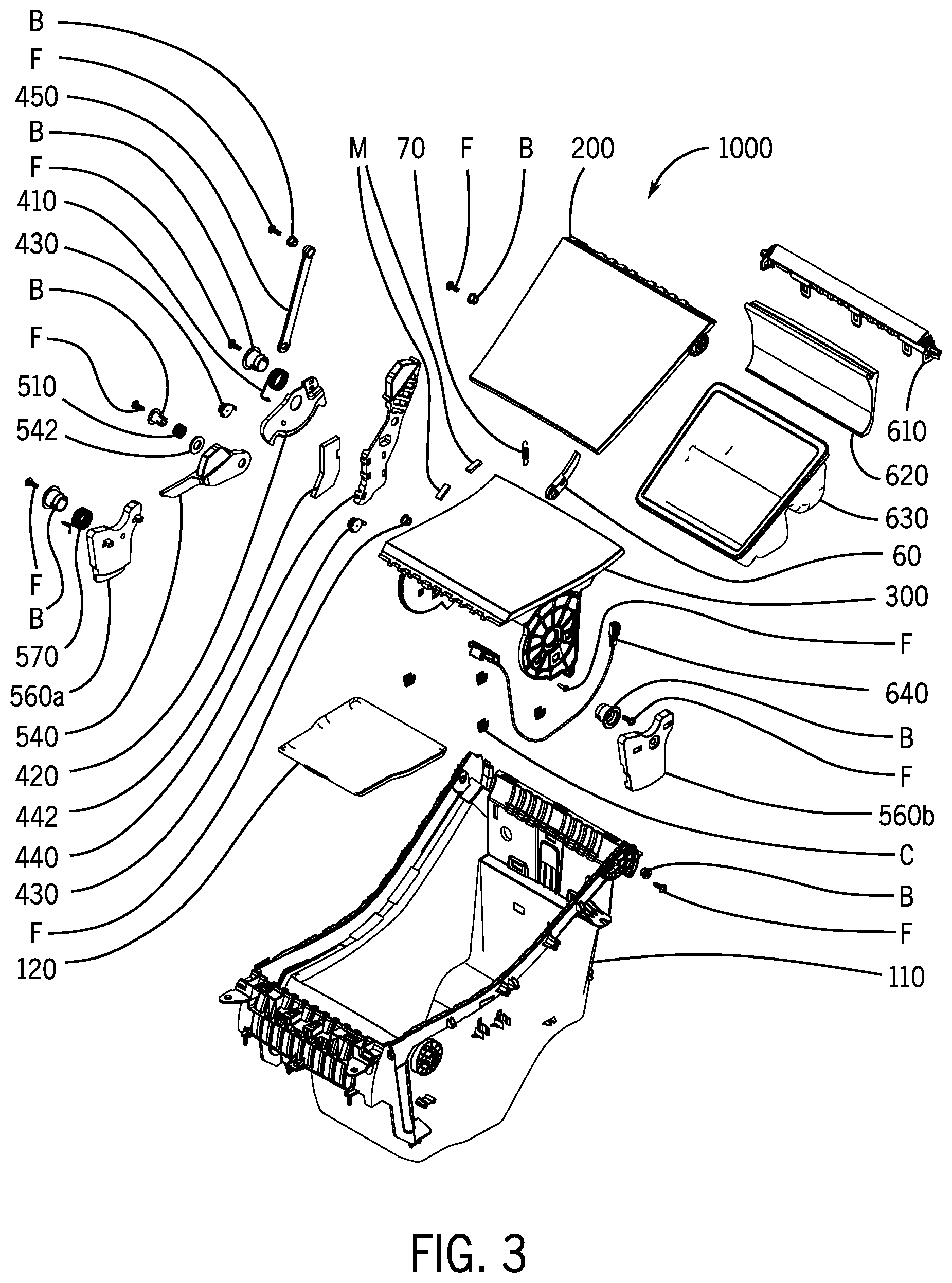
FIG. 3 is a schematic exploded perspective view of a vehicle interior component shown as a console assembly according to an exemplary embodiment.
FIG. 4 is a schematic exploded perspective view of a vehicle interior component shown as a console assembly according to an exemplary embodiment.
FIG. 5 is a schematic exploded perspective view of a vehicle interior component shown as a console assembly according to an exemplary embodiment.
FIG. 6A is a schematic perspective view of a vehicle interior component shown as a console assembly according to an exemplary embodiment.
FIG. 6B is a schematic fragmentary perspective view of a magnet arrangement of a vehicle interior component shown as a console assembly according to an exemplary embodiment.
FIGS. 7A through 7E are schematic side views of the operation of a vehicle interior component shown as a console assembly according to an exemplary embodiment.
FIGS. 8A through 8E are schematic side views of the operation of a vehicle interior component shown as a console assembly according to an exemplary embodiment.
FIGS. 9A through 9E are schematic side views of the operation of a vehicle interior component shown as a console assembly according to an exemplary embodiment.
FIGS. 10A through 10E are schematic side views of the operation of a vehicle interior component shown as a console assembly according to an exemplary embodiment.
FIGS. 11A through 11F are schematic side views of the operation of a vehicle interior component shown as a console assembly according to an exemplary embodiment.
FIGS. 12A through 12E are schematic side views of the operation of a vehicle interior component shown as a console assembly according to an exemplary embodiment.
FIGS. 13A through 13F are schematic side views of the operation of a vehicle interior component shown as a console assembly according to an exemplary embodiment.
FIGS. 14A through 14E are schematic side views of the operation of a vehicle interior component shown as a console assembly according to an exemplary embodiment.
FIGS. 15A and 15B are schematic fragmentary perspective views of a vehicle interior component shown as a console assembly according to an exemplary embodiment.
FIG. 16A is a schematic exploded perspective view of a vehicle interior component shown as a console assembly according to an exemplary embodiment.
FIG. 16B is a schematic perspective view of a component of a vehicle interior component according to an exemplary embodiment.
FIG. 17 is a schematic exploded perspective view of a vehicle interior component shown as a console assembly according to an exemplary embodiment.
FIG. 18 is a schematic exploded perspective view of a vehicle interior component shown as a console assembly according to an exemplary embodiment.
FIG. 19 is a schematic exploded perspective view of a vehicle interior component shown as a console assembly according to an exemplary embodiment.
FIG. 20 is a schematic perspective view of a vehicle interior component shown as a console assembly according to an exemplary embodiment.
FIGS. 21A through 21E are schematic side views of the operation of a vehicle interior component shown as a console assembly according to an exemplary embodiment.
FIGS. 22A through 22E are schematic side views of the operation of a vehicle interior component shown as a console assembly according to an exemplary embodiment.
FIGS. 23A through 23E are schematic side views of the operation of a vehicle interior component shown as a console assembly according to an exemplary embodiment.
FIGS. 24A through 24E are schematic side views of the operation of a vehicle interior component shown as a console assembly according to an exemplary embodiment.
FIGS. 25A through 25F are schematic side views of the operation of a vehicle interior component shown as a console assembly according to an exemplary embodiment.
FIGS. 26A through 26E are schematic side views of the operation of a vehicle interior component shown as a console assembly according to an exemplary embodiment.
FIGS. 27A through 27F are schematic side views of the operation of a vehicle interior component shown as a console assembly according to an exemplary embodiment.
FIGS. 28A through 28E are schematic side views of the operation of a vehicle interior component shown as a console assembly according to an exemplary embodiment.
FIGS. 29A and 29B are schematic fragmentary perspective views of a vehicle interior component shown as a console assembly according to an exemplary embodiment.
FIGS. 30A and 30B are schematic partial exploded views of components for a vehicle interior component according to an exemplary embodiment.
FIGS. 31A through 31F are schematic side views of the operation of a vehicle interior component shown as a console assembly according to an exemplary embodiment.
FIGS. 32A through 32F are schematic side views of the operation of a vehicle interior component shown as a console assembly according to an exemplary embodiment.
FIGS. 33A through 33F are schematic side views of the operation of a vehicle interior component shown as a console assembly according to an exemplary embodiment.
FIG. 34 is a schematic partial perspective view of a vehicle interior component shown as a console assembly according to an exemplary embodiment.
FIGS. 35A through 35E are schematic side views of the operation of a vehicle interior component shown as a console assembly according to an exemplary embodiment.
FIGS. 36A and 36B are schematic partial side views of a latch component of a vehicle interior component according to an exemplary embodiment.
FIGS. 37A through 37F are schematic side views of the operation of a vehicle interior component shown as a console assembly according to an exemplary embodiment.
DESCRIPTION
Referring to FIGS. 1A and 1B, a vehicle V is shown schematically including an interior I with a floor console FC. According to an exemplary embodiment, a console shown as floor console FC may comprise a door configured to move between a closed position and an open position; floor console FC may provide a storage compartment within floor console FC; the door may facilitate access of the storage compartment.
Referring to FIGS. 2A through 2D, a console/assembly shown as floor console/assembly FC is shown schematically in a vehicle interior according to an exemplary embodiment; as indicated, the floor console assembly FC provides a set of opposing doors shown as front door FD and rear door RD which may be opened and closed (e.g. to provide and/or restrict access to a storage compartment/volume within the base of the floor console).
Referring to FIG. 3 through 6A, components of a console assembly shown as floor console assembly 1000 are indicated schematically according to an exemplary embodiment. As indicated schematically, the floor console assembly 1000 comprises a base shown as bin 110 providing the compartment with an opening and a cover comprising a set of opposing doors/assemblies shown as front door assembly 200 (with a mechanism/assembly 400) and a rear door assembly 300 (with a mechanism/assembly 500) sharing the opening/compartment of the base. FIG. 4 indicates the front door assembly 200 according to an exemplary embodiment; FIG. 5 indicates schematically the rear door assembly 300. FIG. 6A indicates the floor console assembly 1000 in assembled form. (As indicated schematically/representationally in the FIGURES, the components/subassemblies of the assembly may be secured with fasteners F such as screws/bolts with bushings/washers B and clips C and other indicated related hardware in a manner to provide secure/suitable attachment for the components/subassemblies for installation and use/operation.)
As indicated schematically in FIG. 3, the floor console assembly 1000 may comprise an internal tray/assembly with tray/bin 630 installed (e.g. free and/or hinged within base under the front door to contain one or more electronic devices) with components including bracket/mounting 620 and trim/strip 610; the floor console assembly may also comprise a lighting arrangement shown schematically/representationally as comprising a LED lamp 640 to be installed (e.g. within base); the floor console may also comprise one or more modules to provide electronic power (e.g. for electronic devices and/or LED lighting, etc.). See also FIGS. 6A, 17 and 20. A spring/lock arrangement (shown schematically as comprising lock 60 and spring 70) may be provided for the floor console assembly 1000 (e.g. conventional inertia lock to retain the cover/door closed in the event of impact loading) according to an exemplary embodiment. See FIG. 3. Referring to FIGS. 16A-16B, 17-19 and FIG. 20, components of a console assembly shown as floor console assembly 2000x and 2000 are shown according to an exemplary embodiment (as indicated with certain components/subassemblies substantially identical to components/subassemblies of console assembly 1000, compare FIGS. 3-6A and 15A-15B with FIGS. 16A-16B and 17-20).
Front Door Assembly of Console
Referring to FIG. 4, the front door assembly 200 with mechanism/assembly 400 is shown schematically according to an exemplary embodiment. The front door assembly 200 comprises a cover/door 210 with a set of flanges to provide a hinge arrangement with the base 110 and is pivotally coupled to the mechanism/assembly 400 by a link arm 450. The front door assembly 200 comprises a latch arrangement shown schematically as a magnetic latch arrangement comprising a magnet M in a slot or housing of the cover/door 210 and a magnet M in a slot or housing at an end/projection of an arm 440. See also FIGS. 3 and 6A. According to an exemplary embodiment, mechanism/assembly 400 is configured to actuate/operate movement of the cover/door 210 from a closed position to an open position. As indicated schematically, mechanism/assembly 400 comprises the link arm 450 pivotally coupled to a cam/disk 420 with a spring shown as torsion spring 410 on a post/bushing for rotation relative to the base 110 (e.g. with the spring configured to urge the door to the open position relative to the base). According to an exemplary embodiment, a damper mechanism shown as comprising a gear damper 430 (e.g. a rotary damper on a pivot/post) to engage with a gear rack on cam/disk 420 is provided for the mechanism/assembly 400. As indicated schematically according to an exemplary embodiment, the arm 440 of the latch mechanism is mounted on a pivot post for rotary movement in a defined path of travel (e.g. to provide for an elevated position and retracted position for the end of the arm configured to engage as the latch arrangement, e.g. with magnet M); arm 440 may be provided at an end with a mass shown as counterweight 442 (e.g. to provide an inertial mass intended to facilitate positioning of the arm/cover). As shown schematically according to an exemplary embodiment in FIG. 4, the arm 440 may be configured with a cam surface to engage the cam/disk 420 during the path of travel; the arm 440 may engage a stop 112 on the base 110 at a terminal position in the path of travel. See also FIGS. 3 and 15A-15B.
As shown schematically in FIGS. 16A and 16B according to an exemplary embodiment, the floor console assembly 2000x comprises a front door assembly with mechanism/assembly 1400. See also FIGS. 3-4 and 15A-15B (as indicated with certain components/subassemblies substantially identical to components/subassemblies of console assembly 1000) and FIG. 20. As shown in FIG. 16A, the front door assembly comprises the cover/door pivotally coupled to the base to the mechanism/assembly 1400 by a link arm 1450 and a cam/disk 1420 (e.g. in a generally planar/aligned arrangement). See also FIG. 16B (showing link arm 1450 with end coupled to and partially nested into a recess in cam/disk 1420). The front door assembly comprises a latch arrangement shown schematically as a magnetic latch arrangement comprising a magnet on a projection/housing at an end of an arm 1440. According to an exemplary embodiment, mechanism/assembly 1400 for the front door assembly is configured to actuate/operate movement of the cover/door from a closed position to an open position. As indicated schematically, mechanism/assembly 1400 comprises the link arm 1450 pivotally coupled to the cam/disk 1420 with a spring shown as torsion spring on a post/bushing for rotation relative to the base (e.g. with the spring configured to urge the door to the open position relative to the base). As indicated schematically according to an exemplary embodiment, the arm 1440 of the latch mechanism is mounted on a pivot post for rotary movement in a defined path of travel (e.g. to provide for an elevated position and retracted position for the end of the arm configured to engage as the latch arrangement, e.g. with magnet). As shown schematically, the arm 1440 may be configured with a cam surface to engage the cam/disk 1420 during the path of travel; the arm 1440 may engage a stop on the base at a terminal position in the path of travel. According to an exemplary embodiment spring/mass arrangement (shown schematically as comprising mass 1442 and spring 1444) may be provided for the floor console assembly (e.g. conventional inertia mass/lock to retain the front cover/door closed in the event of impact loading) according to an exemplary embodiment. See also FIG. 3 (e.g. providing counterweight 442).
As shown schematically in FIGS. 17, 18 and 20 according to an exemplary embodiment, the floor console assembly 2000 comprises a front door assembly 2200 with mechanism/assembly 2400. See also FIGS. 3-4 and 15A-15B (as indicated with certain components/subassemblies substantially identical to components/subassemblies of console assembly 1000) and FIGS. 20 and 29A-29B. As shown in FIGS. 17, 18 and 20, the front door assembly 2200 comprises the cover/door 2210 pivotally coupled to the base 2110 by the mechanism/assembly 2400 having a link arm 2450 and a cam/disk 2420 (e.g. in a generally planar/aligned arrangement); a latch arrangement shown schematically as a magnetic latch arrangement comprising a magnet on a projection/housing at an end of an arm 2440 is provided. According to an exemplary embodiment, mechanism/assembly 2400 for the front door assembly 2200 is configured to actuate/operate movement of the cover/door 2210 from a closed position to an open position. As indicated schematically, mechanism/assembly 2400 comprises the link arm 2450 pivotally coupled to the cam/disk 2420 with a spring shown as torsion spring on a post/bushing for rotation relative to the base (e.g. with the spring configured to urge the door to the open position relative to the base). As indicated schematically according to an exemplary embodiment, the arm 1440 of the latch mechanism is mounted on a pivot post for rotary movement in a defined path of travel (e.g. to provide for an elevated position and retracted position for the end of the arm configured to engage as the latch arrangement, e.g. with magnet). See also FIGS. 29A-29B. As shown schematically, the arm 2440 may be configured with a cam surface to engage the cam/disk 2420 during the path of travel; the arm 2440 may engage a stop on the base at a terminal position in the path of travel. As shown schematically according to an exemplary embodiment in FIGS. 17-18 and 29A-29B, the front door assembly may comprise a latch arrangement (shown as a push-push latch 2080 with a post/plunger on the arm 2440 and base/receptor) to retain the arm 2440 in the retracted position. See also FIGS. 36A-36B.
Rear Door Assembly of Console
Referring to FIG. 5, the rear door assembly 300 with mechanism/assembly 500 is shown schematically according to an exemplary embodiment. The rear door assembly 300 comprises a cover/door 310 with a set of flanges to provide a hinge arrangement with the base 110 and is coupled to the mechanism/assembly 500 (e.g. mounted at a pivot point). The rear door assembly 300 comprises a latch arrangement shown schematically as a magnetic latch arrangement comprising a magnet M in a slot or housing of the cover/door 310 and a magnet M in a slot or housing on a projection of arm 540. See also FIGS. 6A and 15A-15B. According to an exemplary embodiment, mechanism/assembly 500 is configured to actuate/operate movement of the cover/door 310 from a closed position to an open position. As indicated schematically, mechanism/assembly 500 comprises a cam/disk shown as a counterweight 560a (e.g. on a flange of door 310 along with counterweight 560b on the opposing flange of door 310) with a spring shown as torsion spring 570 on a post/bushing for rotation relative to the base 110 (e.g. with the spring configured to urge the door to the open position relative to the base). According to an exemplary embodiment, a damper mechanism shown as comprising a gear damper 430 (e.g. a rotary damper on a pivot/post) is provided to engage with a gear rack on a flange of the door 310. As indicated schematically according to an exemplary embodiment, the arm 540 is mounted on a pivot post for rotary movement in a defined path of travel (e.g. to provide for an elevated position and retracted position for the projection of the arm configured to engage as the latch arrangement, e.g. with magnet M); arm 540 may be provided at an end with a cam surface to engage the cam/disk shown as counterweight 560a (e.g. to facilitate positioning of the arm) during the path of travel; the arm 540 may engage a stop 114 on the base 110 at a terminal position in the path of travel. See also FIGS. 15A-15B.
Referring to FIGS. 19 and 20, components of console assembly shown as floor console assembly 2000 are shown schematically according to an exemplary embodiment. See also FIGS. 3 and 5 and 15A-15B (as indicated with certain components/subassemblies substantially identical to components/subassemblies of console assembly 1000) and FIG. 20. As shown schematically in FIGS. 19 and 20 according to an exemplary embodiment, the floor console assembly 2000 comprises a rear door assembly 2300 with mechanism/assembly 2500. As shown in FIGS. 19 and 20, the rear door assembly 2300 comprises a cover/door 2310 with a set of flanges to provide a hinge arrangement with the base 2110 and is coupled to the mechanism/assembly 2500 (e.g. mounted at a pivot point). The rear door assembly 2300 comprises a latch arrangement shown schematically as a magnetic latch arrangement comprising a magnet in a slot or housing of the cover/door and a magnet in a slot or housing on a projection of arm 2540. See also FIGS. 29A-29B. According to an exemplary embodiment, mechanism/assembly 2500 is configured to actuate/operate movement of the rear cover/door 2310 from a closed position to an open position. As indicated schematically, mechanism/assembly 2500 comprises a cam/disk shown as a counterweight 2560a (e.g. on a flange of door along with counterweight 2560b on the opposing flange of the door) with a spring shown as torsion spring on a post/bushing for rotation relative to the base 2110 (e.g. with the spring configured to urge the door to the open position relative to the base). According to an exemplary embodiment, a damper mechanism shown as comprising a gear damper (e.g. a rotary damper on a pivot/post) is provided to engage with a gear rack on a flange of the door. As indicated schematically according to an exemplary embodiment, the arm 2540 is mounted on a pivot post for rotary movement in a defined path of travel (e.g. to provide for an elevated position and retracted position for the projection of the arm configured to engage as the latch arrangement, e.g. with magnet). As shown schematically according to an exemplary embodiment in FIGS. 19 and 29A-29B, the rear door assembly may comprise a latch arrangement (shown as a push-push latch 2080 with a post/plunger on the end of the arm 2540 and base/receptor) to retain the arm 2540 in the retracted position. See also FIGS. 36A-36B.
Console Assembly
As shown schematically according to an exemplary embodiment in FIG. 6A, when assembled the floor console assembly 1000 comprises a base 110 with a cover that may comprise a front door assembly 200 with mechanism/assembly 400 and a rear door assembly 300 with a mechanism/assembly 500. As shown schematically according to an exemplary embodiment in FIG. 20, when assembled the floor console assembly 2000 comprises a base 2110 with a cover that may comprise a front door assembly 2200 with mechanism/assembly 2400 and a rear door assembly 2300 with a mechanism/assembly 2500. As indicated schematically in FIGS. 6A and 20, the front door assembly and rear door assembly of the floor console assembly may be provided in any of a variety of arrangements according to an exemplary embodiment. See also FIGS. 2A-2D, 15A-15B, 29A-29B and 30A-30B. According to an exemplary embodiment, the components of the console assembly may be formed from materials such as plastic materials and metals (e.g. for mechanism components, fasteners, etc.) and other materials/elements, etc. of a type suitably and/or conventionally used for automotive/vehicle interior components.
As indicated schematically in FIGS. 15A-15B and 29A-29B according to an exemplary embodiment, the cover (e.g. any/each door) of the floor console assembly may be selectively opened and closed as facilitated by the mechanism/assembly; the cover may be retained in a closed position by the latch arrangement (e.g. by the magnetic latch mechanism comprising the arm with magnet to engage the cover with magnet). See also FIGS. 2A-2D, 30A-30B and 34. As shown schematically according to an exemplary embodiment in FIGS. 15A-15B, 29A-29B and 34, a magnetic latch arrangement may be provided with a set of magnets M in a configuration to provide magnetic forces (e.g. magnetic attraction) to establish retention of the cover/door to the base when the cover/door is in the closed position relative to the base. See also FIG. 6B (according to an embodiment shown schematically using a set of magnets Mx for the cover/door and with the base configured to establish magnetic attraction when aligned according to complementary magnetic polarity).
As indicated schematically in FIGS. 2A-2D, 3, 6A-6B, 15A-15B, 29A-29B and 34, the structural components for the magnetic latch arrangement may be formed from a variety of suitable materials including plastic materials (e.g. non-magnetic/non-metallic) for associated parts such as housings, etc.; the magnetic components may comprise any of a variety of suitable magnet components (e.g. magnets configured to provide suitable magnetic forces for retention/separation of the cover/door in operation); according to an exemplary embodiment, the magnetic latch arrangement may comprise a combination of magnetic components (e.g. magnets) and metallic components that may be retained by the magnetic components (e.g. by magnetic attraction) (e.g. a magnet element and a ferro-magnetic element). See also FIGS. 2A-2D and 3, 6A, 17, 20 and 30A-30B (e.g. a magnetic material element M may be paired with a ferro-magnetic material element M in a set to provide a magnetic latch arrangement according to an exemplary embodiment).
As indicated schematically according to an exemplary embodiment in FIGS. 15A-15B and 29A-29B, the base of the floor console assembly may comprise a set of sidewalls that provide a slot for the arm of the latch mechanism of each door (e.g. the projection/housing of each arm comprising the latch feature such as magnet); the arm of the latch mechanism extends from the slot in the elevated position and is retracted from the slot when in the retracted position. As indicated schematically according to an exemplary embodiment, the latch mechanism may be at least partially concealed within the sidewall of the base from general view according to an exemplary embodiment. See e.g. FIGS. 2A-2D, 6A-6B, 15A-15B, 20, 29A-29B and 30A-30B.
As indicated schematically, the latch mechanism for the cover (e.g. each door) may be provided in an asymmetrical arrangement (e.g. with arrangement at/on one sidewall) according to an exemplary embodiment as shown in FIGS. 15A-15B and 29A-29B and 34; according to an exemplary embodiment, the latch mechanism for the cover may be provided on each of the opposing sidewalls (e.g. in a dual latch arrangement with duplication of components on each sidewall to provide additional/symmetrical retaining force).
As indicated schematically according to an exemplary in FIGS. 29A-29B, the latch mechanism may comprise a latch (shown as a push-push latch arrangement 2080) to retain the arm 2440 and 2540 of the latch mechanism in a retracted position (and to act as a stop for the arm). See also FIGS. 36A-36B (push-push latch arrangement 4200 according to an exemplary embodiment).
Operation of Front Door of Console
Referring to FIGS. 7A-7E, 8A-8E, 9A-9E and 10A-10E, operation of the front door assembly of a console assembly shown as floor console assembly 1000 is shown schematically according to an exemplary embodiment. See also FIGS. 21A-21E, 22A-22E, 23A-23E and 24A-24E.
As indicated schematically in FIGS. 7A-7E and 9A-9E, the cover/front door 210 can be moved from a closed position to an open position. As shown schematically, when the cover/door 210 is closed the latch arrangement/mechanism is engaged and is intended to retain the cover/door 210 in the closed position (e.g. closed relative to the base/bin 110 against the force of the spring 410); the end/housing of the arm 440 of the latch mechanism is urged into an elevated position so that magnet M in the end/housing of the arm 440 can engage magnet M in housing of the door 210; engagement of the magnet arrangement (e.g. magnetic attraction/force through each corresponding housing) retains the cover/door in the closed position relative to the base. See FIGS. 7A and 9A. By application of an external force shown as the hand/finger (e.g. shown as hand H in FIG. 7A) of a vehicle occupant, the closed door 210 is rotated/pushed (e.g. downward) and the end/housing of arm 440 of the latch mechanism with magnet M is rotated/translated into a retracted position; when the end/housing of the arm 440 of the latch mechanism is on the retracted position the magnet M in the end/housing of the arm 440 is moved out of complete engagement with magnet M in housing of cover/door 210 (e.g. to reduce the magnetic attraction/force to disengage the latch arrangement) and as to allow the force of spring 410 to move the cover/door 210 toward the open position. See FIGS. 7B and 9B. As the cover/door 210 moved to the fully open position by operation of the link 450 coupled to the cam/disk 420 (and spring 410), the cam/disk 420 engages a cam/surface on the arm 440 to return the end/housing on the arm 440 to the elevated position (e.g. with the magnetic latch arrangement ready for re-engagement when the door is moved to the closed position). See FIGS. 7C-7E and 9C-9E.
As indicated schematically in FIGS. 8A-8E and 10A-10E, the cover/front door 210 can be moved from the open position to the closed position. As shown schematically, when the cover/door 210 is open relative to the base the cover/door will tend to remain open (e.g. by force of the spring 410). See FIGS. 8A and 10A. By application of an external force shown as the hand/finger (e.g. shown as hand H in FIG. 8B) of a vehicle occupant, the open door 210 is rotated/pushed (e.g. downward) toward the closed position (e.g. against the force of spring 410). See FIGS. 8B-8D and 10B-10D. As the cover/door 210 is moved to the fully closed position the housing with magnet M of the cover 210 engages the end/housing with magnet M on the arm 440 (e.g. in the elevated position) and the latch arrangement/mechanism (e.g. magnetic latch arrangement) is re-engaged to retain the door 210 in the closed position. See FIGS. 8E and 10E.
Referring to FIGS. 21A-21E, 22A-22E, 23A-23E and 24A-24E, operation of the front door assembly is shown schematically for a console assembly shown as floor console assembly 2000 according to an exemplary embodiment.
As indicated schematically in FIGS. 21A-21E and 22A-22E, the cover/front door can be moved from a closed position to an open position. As shown schematically, when the cover/door is closed the latch arrangement/mechanism is engaged and is intended to retain the cover/door in the closed position (e.g. closed relative to the base/bin against the force of the spring of the mechanism/assembly 2400); the end/housing of the arm 2440 of the latch mechanism is urged into an elevated position so that magnet M in the end/housing of the arm 2440 can engage magnet M in housing of the door; engagement of the magnet arrangement (e.g. magnetic attraction/force through each corresponding housing) retains the cover/door in the closed position relative to the base; post of the arm 2440 is disengaged from the latch mechanism shown as push-push latch 2080 (with latch base/receptor). See FIGS. 21A and 23A. By application of an external force shown as the hand/finger of a vehicle occupant, the closed door is rotated/pushed (e.g. downward) and the end/housing of arm 2440 is rotated/pushed toward the retracted position so that the post of the arm 2440 is engaged and latched with the latch mechanism shown as push-push latch 2080 (with latch base/receptor); the end/housing of arm 2440 of the latch mechanism with magnet M is rotated/translated into a retracted position; when the end/housing of the arm 2440 of the latch mechanism is in the retracted position the magnet M in the end/housing of the arm 2440 is moved out of complete engagement with magnet M in housing of cover/door (e.g. to reduce the magnetic attraction/force to disengage the latch arrangement) and as to allow the force of spring to move the cover/door toward the open position. See FIGS. 21B and 23B. The cover/door is moved to the fully open position by operation of the link 2450 coupled to the cam/disk 2420 (and spring); the arm 2440 is retained in the retracted position by the push-push latch 2080. See FIGS. 21C-21E and 23C-23E. As shown schematically in FIGS. 21E and 23E, when the cover/door is in the open position the post of the arm 2440 remains engaged with the push-push latch 2080 (with latch base/receptor) to retain the arm 2440 in the retracted position.
As indicated schematically in FIGS. 22A-22E and 24A-24E, the cover/front door can be moved from the open position to the closed position. As shown schematically, when the cover/door is open relative to the base the cover/door will tend to remain open (e.g. by force of the spring 410 as shown schematically in FIG. 7E); the post of the arm 2440 remains engaged with the push-push latch 2080 (with latch base/receptor) to retain the arm 2440 in the retracted position. See FIGS. 22A and 24A. By application of an external force shown as the hand/finger of a vehicle occupant, the open door is rotated/pushed (e.g. downward) toward the closed position (e.g. against the force of spring of the mechanism/assembly 2400). See FIGS. 22B-22C and 24B-24C. As the cover/door is moved toward and slightly past the fully closed position the housing with magnet M of the cover engages the end/housing with magnet M on the arm 2440 (which is in the retracted position); as the cover/door is moved (slightly) past the fully closed position the post of the arm 2440 disengages from the push-push latch 2080 (with latch base/receptor) to release the arm 2440 from the retracted position. See FIGS. 22D and 24D. As the external force is released from the cover/door and the arm 2440 moves to the elevated position, the magnet M of the cover engages the magnet M of the arm 2440 and the latch arrangement/mechanism (e.g. magnetic latch arrangement) is re-engaged to retain the door in the closed position. See FIGS. 22E and 24E. As shown schematically in FIGS. 22E and 24E, with the cover/door in the closed position the post of the arm 2440 is disengaged with the push-push latch 2080 (with latch base/receptor) and the arm 2440 is in the elevated position (e.g. actuated into the elevated position by the spring).
As shown schematically, in common use/operation by application of an external force (e.g. such as from hand H of a vehicle occupant) the cover/front door when in the closed position is able to be moved to the open position as indicated and when in the open position is able to be moved to the closed position. See e.g. FIGS. 2A-2D, 7A-7E and 8A-8E.
Operation of Rear Door of Console
Referring to FIGS. 11A-11F, 12A-12E, 13A-13F and 14A-14E, operation of the rear door assembly of the floor console assembly is shown schematically according to an exemplary embodiment. See also FIGS. 25A-25E, 26A-26E, 27A-27E and 28A-28E.
As indicated schematically in FIGS. 11A-11F and 13A-13F, the cover/rear door 310 can be moved from a closed position to an open position. As shown schematically, when the cover/door 310 is closed the latch arrangement/mechanism is engaged and is intended to retain the cover/door 310 in the closed position (e.g. closed relative to the base/bin 110 against the force of the spring 570); the projection/housing of the arm 540 of the latch mechanism is urged into an elevated position so that magnet M in the projection/housing of the arm 540 can engage magnet M in housing of the door 310; engagement of the magnet arrangement (e.g. magnetic attraction/force through each corresponding housing) retains the cover/door in the closed position relative to the base. See FIGS. 11A and 13A. By application of an external force shown as the hand/finger (e.g. shown as hand H in FIG. 11A) of a vehicle occupant, the closed door 310 is rotated/pushed (e.g. downward) and the projection/housing of arm 540 of the latch mechanism with magnet M is rotated/translated into a retracted position; when the projection/housing of the arm 540 of the latch mechanism is in the retracted position the magnet M in the projection/housing of the arm 540 is moved out of complete engagement with magnet M in housing of cover/door 310 (e.g. to reduce the magnetic attraction/force to disengage the latch arrangement) and as to allow the force of spring 570 with counterweights 560a and 560b to move the cover/door 310 toward the open position. See FIGS. 11B and 13B. As the cover/door 310 moved to the fully open position (e.g. by operation of the counterweights 560a/560b and spring 570), the cam surface of counterweight 560a engages a cam/surface on the arm 540 to return the projection/housing on the arm 440 to the elevated position (e.g. with the magnetic latch arrangement ready for re-engagement when the door is moved to the closed position). See FIGS. 11C-11F and 13C-13F.
As indicated schematically in FIGS. 12A-12E and 14A-14E, the cover/rear door 310 can be moved from the open position to the closed position. As shown schematically, when the cover/door 310 is open relative to the base the cover/door will tend to remain open (e.g. by force of the spring 570). See FIGS. 12A and 14A. By application of an external force shown as the hand/finger (e.g. shown as hand H in FIG. 12B) of a vehicle occupant, the open door 310 is rotated/pushed (e.g. downward) toward the closed position (e.g. against the force of spring 570). See FIGS. 12B-12D and 14B-14D. As the cover/door 310 moved to the fully closed position the housing with magnet M of the cover 310 engages the projection/housing with magnet M on the arm 540 (e.g. in the elevated position) and the latch arrangement/mechanism (e.g. magnetic latch arrangement) is re-engaged to retain the door 310 in the closed position. See FIGS. 12E and 14E.
Referring to FIGS. 25A-25F, 26A-26E, 27A-27F and 28A-28E, operation of the rear door assembly is shown schematically for a console assembly shown as floor console assembly 2000 according to an exemplary embodiment.
As indicated schematically in FIGS. 25A-25F and 27A-27F, the cover/rear door can be moved from a closed position to an open position. As shown schematically, when the cover/door is closed the latch arrangement/mechanism is engaged and is intended to retain the cover/door in the closed position (e.g. closed relative to the base/bin against the force of the spring of the mechanism/assembly 2500); the projection/housing of the arm 2540 of the latch mechanism is urged into an elevated position so that magnet M in the projection/housing of the arm 2540 can engage magnet M in housing of the door; engagement of the magnet arrangement (e.g. magnetic attraction/force through each corresponding housing) retains the cover/door in the closed position relative to the base; end/post of the arm 2540 is disengaged from the latch mechanism shown as push-push latch 2080 (with latch base/receptor). See FIGS. 25A and 27A. By application of an external force shown as the hand/finger of a vehicle occupant, the closed door is rotated/pushed (e.g. downward) and the projection/housing of arm 2540 is rotated/pushed toward the retracted position so that the end/post of the arm 2540 is engaged and latched with the latch mechanism shown as push-push latch 2080 (with latch base/receptor); the projection/housing of arm 2540 of the latch mechanism with magnet M is rotated/translated into a retracted position; when the projection/housing of the arm 2540 of the latch mechanism is in the retracted position the magnet M in the projection/housing of the arm 2540 is moved out of complete engagement with magnet M in housing of cover/door (e.g. to reduce the magnetic attraction/force to disengage the latch arrangement) and as to allow the force of spring to move the cover/door toward the open position. See FIGS. 25B and 27B. The cover/door is moved to the fully open position by operation of the mechanism/assembly 2500; the arm 2540 is retained by the push-push latch 2080 in the retracted position (e.g. with the push-push latch engaged to retain the end/post of the arm). See FIGS. 25C-25E and 27C-27E. As shown schematically in FIGS. 25F and 27F, with the cover door in the open position the end/post of the arm 2540 remains engaged with the push-push latch 2080 (with latch base/receptor) to retain the arm 2540 in the retracted position.
As indicated schematically in FIGS. 26A-26E and 28A-28E, the cover/front door can be moved from the open position to the closed position. As shown schematically, when the cover/door is open relative to the base the cover/door will tend to remain open (e.g. by force of the spring of the mechanism/assembly 2500); the end/post of the arm 2540 remains engaged with the push-push latch 2080 (with latch base/receptor) to retain the arm 2540 in the retracted position. See FIGS. 26A and 28A. By application of an external force shown as the hand/finger of a vehicle occupant, the open door is rotated/pushed (e.g. downward) toward the closed position (e.g. against the force of spring of the mechanism/assembly 2500). See FIGS. 26B-26C and 28B-28C. As the cover/door is moved toward and slightly past the fully closed position the housing with magnet M of the cover engages the projection/housing with magnet M on the arm 2540 (which is in the retracted position); as the cover/door is moved (slightly) past the fully closed position the end/post of the arm 2540 disengages from the push-push latch 2080 (with latch base/receptor) to release the arm 2540 from the retracted position. See FIGS. 26D and 28D. As the external force is released from the cover/door and the arm 2540 moves to the elevated position, the magnet M of the cover engages the magnet M of the arm 2540 and the latch arrangement/mechanism (e.g. magnetic latch arrangement) is re-engaged to retain the door in the closed position. See FIGS. 26E and 28E. As shown schematically in FIGS. 26E and 28E, the end/post of the arm 2540 is disengaged with the push-push latch 2080 (with latch base/receptor) and the arm 2540 is in the elevated position (e.g. actuated into the elevated position by a spring).
As shown schematically, in common use/operation by application of an external force (e.g. such as from hand H of a vehicle occupant) the cover/rear door when in the closed position is able to be moved to the open position as indicated and when in the open position is able to be moved to the closed position. See e.g. FIGS. 2A-2D, 11A-11F and 12A-12E.
Operation of Magnetic Latch Arrangement/Latch Mechanism
According to an exemplary embodiment shown schematically in FIGS. 35A-35E, 36A-36B and 37A-37E, the floor console assembly with a magnetic latch arrangement comprising magnet M installed on cover 4120 (e.g. in a housing on cover) and magnet M installed on arm 4130 (e.g. in a projection/housing on arm) of the mechanism/subassembly (shown partially) to operate the cover 4120. See also FIGS. 3 and 6A and 30A-34 (general schematic/representational views of floor console assembly with mechanism/assembly for cover/door). As shown schematically, the floor console assembly may comprise a latch arrangement 4200 for an arm configured to retain the arm of the mechanism/assembly in a retracted position for unlatching to enable the magnetic latch arrangement for the cover 4120 and base/arm 4110/4130 to disengage and the cover 4120 to separate from the base 4110 for opening; as indicated schematically, the arm 4130 is movable between an elevated position (e.g. against a stop 4134) and a retracted position (e.g. engaged with the latch arrangement 4200) coupled to a spring 4160 (shown schematically) tending to urge the arm 4130 toward the elevated position. See FIGS. 35A-35E and 37A-37F.
As shown schematically in FIGS. 35A-35E and 36A and 36B, according to an exemplary embodiment the latch arrangement 4200 for arm 4130 may comprise a push-push latch (e.g. of a conventional type); according to an exemplary embodiment, the push-push latch arrangement may comprise a base 4204 (e.g. latch receptor) providing a pocket with a retaining mechanism shown as grippers 4204a and 4204b into which a pin or plunger 4202 shown as post 4202a will be engaged. As shown in FIGS. 36A and 36B, when pin/post 4202a is separated from base 4204 the insertion of the pin/post 4202a into the base 4204 (e.g. pocket with grippers 4204a/4204b) will engage the latch mechanism to retain pin/post 4202a in base 4204 (e.g. latching action); when pin/post 4202a is retained in base 4204 then pushing on pin/post 4202a will cause base 4204 to release/disengage with pin/post 4202a (e.g. unlatching action). See also FIGS. 17-20 and 21A-E through 29A-29E (exemplary embodiment implementation of latch arrangement shown as push-push latch arrangement for arm of latch mechanism).
Referring to FIGS. 35A-35E a sequence of opening the cover from the base is shown schematically according to an exemplary embodiment. As shown, the cover 4120 is closed and the magnetic latch arrangement is engaged; the projection/housing with arm 4130 is in an elevated position (e.g. actuated by a spring and against a stop) and the latch arrangement 4200 for arm (e.g. push-push latch mechanism) is disengaged. See FIGS. 35A and 35B. To open the cover 4120 from the base an external force (shown as a downward force applied by the hand H of a vehicle operator) is applied to the cover 4120 which moves the projection/housing of the arm 4130 toward the retracted position (e.g. moved against the spring force) to disengage the magnetic latch arrangement (e.g. by shifting relative position of the magnets to effect a reduction in magnetic attraction/force between the magnets); the latch arrangement 4200 for arm (e.g. push-push latch mechanism) is engaged and the arm 4130 is retained in the retracted position. See FIGS. 35C and 35D. As shown schematically in FIG. 35E, when the magnetic latch arrangement is disengaged and the latch arrangement 4200 is engaged (e.g. to keep the magnetic latch arrangement from re-engaging) the cover 4120 (e.g. by action of a spring) is urged to the open position.
Referring to FIGS. 37A-37E a sequence of closing the open cover relative to the base is shown schematically according to an exemplary embodiment. As shown, the cover 4120 is open and the magnetic latch arrangement is disengaged; the projection/housing with arm 4130 is in a retracted position with the latch arrangement 4200 for arm (e.g. push-push latch mechanism) is engaged (retained against the force of the spring 4160 actuating the arm). See FIGS. 37A and 37B. To close the cover 4120 from the base an external force (shown as a downward force applied by the hand H of a vehicle operator) is applied to the cover 4120 (e.g. against a force such as from a spring urging the door open) which moves the projection/housing of the arm 4130 toward the retracted position to disengage the latch arrangement 4200 (e.g. push-push latch arrangement); the latch arrangement 4200 for arm (e.g. push-push latch mechanism) is disengaged and the arm 4130 is moved (e.g. by the force of the spring) to the elevated position (e.g. against a stop 4134 ready for engagement of the magnetic latch arrangement). See FIGS. 35C-35D. As shown schematically in FIGS. 35E and 35F, when the external force (e.g. downward force) on the cover 4120 is released the arm 4130 is urged to the elevated position and magnetic latch arrangement is engaged to retain the cover to the base (while the latch arrangement 4200 remains disengaged).
Exemplary Embodiments--Latch Arrangement
Referring to FIGS. 30A-30B and 34 according to an exemplary embodiment shown schematically, a floor console assembly 3000 may comprise a base 3110 (shown partially) (see also base 110 in FIG. 3) and a door 3120 configured to move between a closed position and an open position. According to an exemplary embodiment, door 3120 may be latched on to base 3110 by a magnet. As shown schematically in FIGS. 2A-2D, a vehicle occupant may push door 3120 inward (e.g. with hand H) to unlatch door 3120 from base 3110 (i.e. to disengage the magnet from base 3110). According to an exemplary embodiment, door 3120 may be spring-loaded to move towards the open position after door 3120 is unlatched from base 3110.
As shown schematically in FIG. 2C, door (shown as 3120 in FIGS. 30A and 30B and in FIG. 34) is partially open; door 3120 is configured to rotate towards the open position without input from a vehicle occupant after door 3120 is unlatched from base 3110. As shown schematically in FIG. 2D, door 3120 is at the open position.
As shown schematically in FIG. 30A, floor console assembly 3000 comprises a base 3110, a door 3120 and a cam 3130. As shown schematically in FIG. 30A, door 3120 is mounted on base 3110 by a pin 3152; door 3120 is configured to rotate around pin 3152 relative to base 3110. According to an exemplary embodiment, door 3120 is configured to move between a closed position and an open position. As shown schematically in FIG. 30A, door 3120 provides a magnet M; cam 3130 provides a magnet M; magnet M on door 3120 and magnet M on cam 3130 are configured to engage one another when door 3120 is at the closed position according to an exemplary embodiment. As shown schematically in FIG. 30A, cam 3130 is mounted on a pin 3132 on base 3110; cam 3130 is configured to pivot around pin 3132 according to an exemplary embodiment; base 3110 also provides a first stop 3134 (i.e. the top stop 3134 in FIG. 30A) and a second stop 3134 (i.e. the bottom stop 3134 in FIG. 30A) configured to constrain the range of motion of cam 3130 (i.e. between first stop 3134 and second stop 3134). As shown schematically in FIG. 30A, a first pin 3162 is mounted on base 3110; a second pin 3162 is mounted on door 3120; floor console 3000 also comprises a spring shown as an extension spring 3160. According to an exemplary embodiment, a first end of extension spring 3160 is attached to first pin 3162 on base 3110; a second end of extension spring 3160 is attached to second pin 3162 on door 3120. According to an exemplary embodiment, extension spring 3160 is configured to rotate door 3120 towards the open position.
As shown schematically in FIG. 30A, base 3110 provides a stop 3170. According to an exemplary embodiment, stop 3170 is configured to stop door 3120 at the open position (e.g. counter the tension from extension spring 3160). As shown schematically in FIG. 30A, floor console 3000 comprises a damper shown as a rotary damper 3154; door 3120 provides teeth 3112 configured to engage with rotary damper 3154. According to an exemplary embodiment, rotary damper 3154 is configured to provide a smooth motion for door 3120 between the closed position and the open position. See also FIG. 34.
As shown schematically in FIG. 30B, floor console assembly 3000 comprises base 3110, door 3120 and a cam 3130. As shown schematically in FIG. 30B, door 3120 is mounted on base 3110 by pin 3152; door 3120 is configured to rotate around pin 3152 relative to base 3110. According to an exemplary embodiment, door 3120 is configured to move between a closed position and an open position. As shown schematically in FIG. 30B, door 3120 provides a magnet M; cam 3130 provides a magnet M; magnet M on door 3120 and magnet M on cam 3130 are configured to engage one another when door 3120 is at the closed position according to an exemplary embodiment. As shown schematically in FIG. 30B, cam 3130 is mounted on a pin 3132 on base 3110; cam 3130 is configured to pivot around pin 3132 according to an exemplary embodiment; base 3110 also provides a first stop 3134 (i.e. the top stop 3134 in FIG. 30B) and a second stop 3134 (i.e. the bottom stop 3134 in FIG. 30B) configured to constrain the range of motion of cam 3130 (i.e. between first stop 3134 and second stop 3134). As shown schematically in FIG. 30B, a spring shown as a torsion spring 3150 is mounted at pin 3152; a first end of torsion spring 3150 is mounted on base 3110; a second end of torsion spring 3150 is mounted on a slot 3122 provided in door 3120. According to an exemplary embodiment, torsion spring 3150 is configured to provide torque at pin 3152 to rotate door 3120 towards the open position. According to an exemplary embodiment, floor console 3100 may utilize torsion spring 3150 and extension spring 3160 to provide torque at pin 3152 to rotate door 3120; floor console 3100 may utilize torsion spring 3150 or extension spring 3160 to provide torque at pin 3152 to rotate door 3120. As shown schematically in FIG. 30B, base 3110 provides a stop 3170. According to an exemplary embodiment, stop 3170 is configured to stop door 3120 at the open position (e.g. counter the tension from torsion spring 3150). As shown schematically in FIG. 30B, floor console 3000 comprises a damper shown as rotary damper 3111; door 3120 provides teeth 3112 configured to engage with rotary damper 3154. According to an exemplary embodiment, rotary damper 3154 is configured to provide a smooth motion for door 3120 between the closed position and the open position.
As shown schematically in FIGS. 31A to 31F, door 3120 moves from the closed position to the open position. As shown schematically in FIG. 31A, door 3120 is at the closed position; magnet M on door 3120 and magnet M on cam 3130 are engaged to keep door 3120 at the closed position; cam 3130 is engaged with first stop 3134. As shown schematically in FIG. 31B, a vehicle occupant pushes on door 3120 (e.g. with hand H) to disengage magnet M on door 3120 and magnet M on cam 3120; cam 3130 is engaged with second stop 3134. As shown schematically in FIGS. 31C and 31D, door 3120 is partially open; extension spring 3160 progressively shortens to pull door 3120 towards the open position; rotary damper 3154 is engaged with teeth 3112 on door 3120. According to an exemplary embodiment, rotary damper 3154 is configured to provide a smooth motion for door 3120 as door 3120 moves between the closed position and the open position. As shown schematically in FIG. 31E, door 3120 is partially open; door 3120 engages with cam 3130; cam 3130 is pushed towards first stop 3134. As shown schematically in FIG. 31F, door 3120 is at the open position; door 3120 engages with stop 3170; cam 3130 engages with first stop 3134.
As shown schematically in FIGS. 32A to 32F, door 3120 moves from the open position to the closed position. As shown schematically in FIG. 32A, door 3120 is at the open position. As shown schematically in FIGS. 32B to 32D, a vehicle occupant pushes door 3120 (e.g. with hand H) towards the closed position; extension spring 3160 is progressively elongated. As shown schematically in FIG. 32E, the distance between magnet M on door 3120 and magnet M on cam 3130 is in proximity to provide magnetic force (e.g. magnetic attraction) to pull door 3120 towards the closed position. See also FIG. 34. As shown schematically in FIG. 32F, magnet M on door 3120 and magnet M on cam 3130 are engaged with one another (e.g. by magnetic attraction); door 3120 is at the closed position.
As shown schematically in FIGS. 32A to 32F, door 3120 moves from the open position to the closed position. As shown schematically in FIG. 32A, door 3120 is at the open position. As shown schematically in FIGS. 32B to 32D, a vehicle occupant pushes door 3120 (e.g. with hand H) towards the closed position; extension spring 3160 is progressively elongated. As shown schematically in FIG. 32E, the distance between magnet M on door 3120 and magnet M on cam 3130 is in proximity to provide magnetic force (e.g. magnetic attraction) to pull door 3120 towards the closed position. See also FIG. 34. As shown schematically in FIG. 32F, magnet M on door 3120 and magnet M on cam 3130 are engaged with one another (e.g. by magnetic attraction); door 3120 is at the closed position.
As shown schematically in FIGS. 33A to 33F, door 3120 moves from the closed position to the open position (e.g. by external force from the fingers/hand of a
D00000
D00001
D00002
D00003
D00004
D00005
D00006
D00007
D00008
D00009
D00010
D00011
D00012

D00013

D00014

D00015

D00016

D00017

D00018

D00019
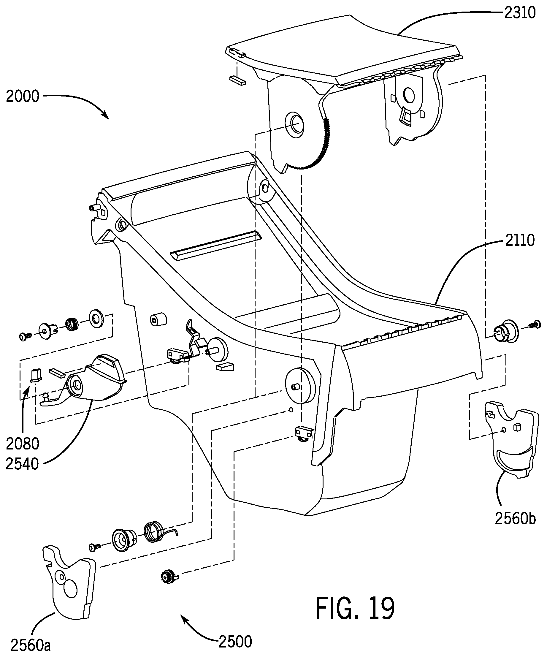
D00020

D00021

D00022

D00023

D00024

D00025

D00026

D00027

D00028

D00029

D00030

D00031

D00032

D00033

D00034

D00035

D00036

D00037

XML
uspto.report is an independent third-party trademark research tool that is not affiliated, endorsed, or sponsored by the United States Patent and Trademark Office (USPTO) or any other governmental organization. The information provided by uspto.report is based on publicly available data at the time of writing and is intended for informational purposes only.
While we strive to provide accurate and up-to-date information, we do not guarantee the accuracy, completeness, reliability, or suitability of the information displayed on this site. The use of this site is at your own risk. Any reliance you place on such information is therefore strictly at your own risk.
All official trademark data, including owner information, should be verified by visiting the official USPTO website at www.uspto.gov. This site is not intended to replace professional legal advice and should not be used as a substitute for consulting with a legal professional who is knowledgeable about trademark law.