Combined nasal and mouth ventilation mask
Pedro , et al.
U.S. patent number 10,589,047 [Application Number 15/272,190] was granted by the patent office on 2020-03-17 for combined nasal and mouth ventilation mask. This patent grant is currently assigned to Revolutionary Medical Devices, Inc.. The grantee listed for this patent is Revolutionary Medical Devices, INC.. Invention is credited to Steven H. Cataldo, David M. Kane, Michael J. Pedro, Ryan Redford, Thomas Reilly.


View All Diagrams
| United States Patent | 10,589,047 |
| Pedro , et al. | March 17, 2020 |
Combined nasal and mouth ventilation mask
Abstract
A gas ventilation mask includes an anesthesia nasal mask and a mouth mask defining respectively a nasal chamber and an oral chamber, detachably connected to one another so that the nasal mask and the mouth mask may be used either separately as a nasal mask or as a mouth mask, or as a combination nasal-mouth mask. Also provided is an anesthesia mask strap system having a first expandable strap portion having the ability to extend; second and third non-expandable strap sections fixed to ends of the first expandable strap section; and an adhesion section for fixing a length of the strap system when the second and third non-expandable strap sections are pulled to tension the expandable strap section.
| Inventors: | Pedro; Michael J. (Brooklyn, NY), Cataldo; Steven H. (New York, NY), Kane; David M. (Tucson, AZ), Reilly; Thomas (Tucson, AZ), Redford; Ryan (Tucson, AZ) | ||||||||||
|---|---|---|---|---|---|---|---|---|---|---|---|
| Applicant: |
|
||||||||||
| Assignee: | Revolutionary Medical Devices,
Inc. (Tucson, AZ) |
||||||||||
| Family ID: | 54767595 | ||||||||||
| Appl. No.: | 15/272,190 | ||||||||||
| Filed: | September 21, 2016 |
Prior Publication Data
| Document Identifier | Publication Date | |
|---|---|---|
| US 20170035979 A1 | Feb 9, 2017 | |
Related U.S. Patent Documents
| Application Number | Filing Date | Patent Number | Issue Date | ||
|---|---|---|---|---|---|
| 15127760 | |||||
| PCT/US2015/034277 | Jun 4, 2015 | ||||
| 62007802 | Jun 4, 2014 | ||||
| 62056293 | Sep 26, 2014 | ||||
| 62060417 | Oct 6, 2014 | ||||
| 62061045 | Oct 7, 2014 | ||||
| 62065504 | Oct 17, 2014 | ||||
| 62091370 | Dec 12, 2014 | ||||
| 62118301 | Feb 19, 2015 | ||||
| 62149313 | Apr 17, 2015 | ||||
| 62161086 | May 13, 2015 | ||||
| 62161093 | May 13, 2015 | ||||
| Current U.S. Class: | 1/1 |
| Current CPC Class: | A61M 16/06 (20130101); A62B 18/00 (20130101); A61M 16/0683 (20130101); A61M 16/009 (20130101); A61M 16/208 (20130101); A61G 13/121 (20130101); A61M 16/104 (20130101); A61M 16/01 (20130101); A61M 16/18 (20130101); A61M 16/0616 (20140204); A61M 2230/432 (20130101); A61M 16/085 (20140204); A61M 2202/0208 (20130101); A61M 2210/0625 (20130101); A61M 2210/0618 (20130101) |
| Current International Class: | A61M 16/06 (20060101); A61G 13/12 (20060101); A61M 16/00 (20060101); A61M 16/10 (20060101); A61M 16/01 (20060101); A61M 16/18 (20060101); A62B 18/00 (20060101); A61M 16/20 (20060101); A61M 16/08 (20060101) |
References Cited [Referenced By]
U.S. Patent Documents
| 1050621 | January 1913 | Ford |
| 1131802 | March 1915 | Stenshoel |
| 1441817 | January 1923 | McCullough |
| 1729525 | September 1929 | Stenshoel |
| 1776167 | September 1930 | Stenshoel |
| 2452816 | November 1948 | Wagner |
| 2843121 | July 1958 | Hudson |
| 2939458 | June 1960 | Lundquist |
| 3013556 | December 1961 | Galleher |
| 3522612 | August 1970 | Palmer |
| 3556097 | January 1971 | Wallace |
| 3779164 | December 1973 | Study |
| 3815596 | June 1974 | Keener et al. |
| 3856051 | December 1974 | Bain |
| 3889668 | June 1975 | Ochs et al. |
| 3897777 | August 1975 | Morrison |
| D242490 | November 1976 | Belkin |
| 4005499 | February 1977 | Klein |
| 4007737 | February 1977 | Paluch |
| 4015598 | April 1977 | Brown |
| 4188946 | February 1980 | Watson et al. |
| D256161 | July 1980 | Oliver |
| 4231363 | November 1980 | Grimes |
| 4232667 | November 1980 | Chalon et al. |
| 4248218 | February 1981 | Fischer |
| 4259757 | April 1981 | Watson |
| 4265235 | May 1981 | Fukunaga |
| 4265239 | May 1981 | Fischer, Jr. et al. |
| 4275720 | June 1981 | Wichman |
| 4328797 | May 1982 | Rollins |
| 4457026 | July 1984 | Morris |
| 4463755 | August 1984 | Suzuki |
| 4471769 | September 1984 | Lockhart |
| 4574796 | March 1986 | Lundstrom |
| 4596246 | June 1986 | Lyall |
| 4657010 | April 1987 | Wright |
| 4700691 | October 1987 | Tari et al. |
| 4770169 | September 1988 | Schmoegner et al. |
| 4905712 | March 1990 | Bowlin et al. |
| 5046200 | September 1991 | Feder |
| 5046491 | September 1991 | Derrick |
| 5121746 | June 1992 | Sikora |
| D333404 | February 1993 | Thompson |
| 5243971 | September 1993 | Sullivan et al. |
| 5255303 | October 1993 | DiMaio et al. |
| 5271390 | December 1993 | Gray et al. |
| 5284160 | February 1994 | Dryden |
| D347494 | May 1994 | Mustelier |
| D354128 | January 1995 | Rinehart |
| 5404873 | April 1995 | Leagre et al. |
| 5462050 | October 1995 | Dahlstrand |
| 5474060 | December 1995 | Evans |
| 5485837 | January 1996 | Solesbee et al. |
| 5524639 | June 1996 | Lanier et al. |
| D373921 | September 1996 | Palomo et al. |
| 5557049 | September 1996 | Ratner |
| RE35339 | October 1996 | Rapoport |
| 5560354 | October 1996 | Berthon-Jones |
| 5586551 | December 1996 | Hilliard |
| 5647357 | July 1997 | Barnett et al. |
| 5649331 | July 1997 | Wilkinson et al. |
| 5660174 | August 1997 | Jacobelli |
| 5661859 | September 1997 | Schaefer |
| 5685298 | November 1997 | Idris |
| 5738094 | April 1998 | Hoftman |
| 5746201 | May 1998 | Kidd |
| 5749358 | May 1998 | Good et al. |
| 5778872 | July 1998 | Fukunaga et al. |
| D402755 | December 1998 | Kwok |
| 5884624 | March 1999 | Barnett et al. |
| 5933886 | August 1999 | Washington |
| 5966763 | October 1999 | Thomas et al. |
| 5975079 | November 1999 | Hellings et al. |
| 5983896 | November 1999 | Fukunaga et al. |
| 6003511 | December 1999 | Fukunaga et al. |
| 6019101 | February 2000 | Cotner et al. |
| 6035852 | March 2000 | Hoftman |
| 6058933 | May 2000 | Good et al. |
| D428987 | August 2000 | Kwok |
| 6112746 | September 2000 | Kwok et al. |
| 6123071 | September 2000 | Berthon-Jones et al. |
| 6129082 | October 2000 | Leagre |
| 6152137 | November 2000 | Schwartz et al. |
| D435650 | December 2000 | Kwok |
| 6192886 | February 2001 | Rudolph |
| 6216691 | April 2001 | Kenyon et al. |
| 6263874 | July 2001 | LeDez et al. |
| 6342040 | January 2002 | Starr et al. |
| 6357441 | March 2002 | Kwok et al. |
| 6397847 | June 2002 | Scarberry et al. |
| 6401713 | June 2002 | Hill |
| 6412487 | July 2002 | Gunaratnam et al. |
| 6412488 | July 2002 | Barnett et al. |
| 6439230 | August 2002 | Gunaratnam et al. |
| 6439231 | August 2002 | Fukunaga et al. |
| 6446288 | September 2002 | Pi |
| 6459923 | October 2002 | Plewes et al. |
| 6463931 | October 2002 | Kwok et al. |
| 6467483 | October 2002 | Kopacko et al. |
| D467345 | December 2002 | Gingles et al. |
| 6513526 | February 2003 | Kwok et al. |
| 6520182 | February 2003 | Gunaratnam |
| 6581602 | June 2003 | Kwok et al. |
| 6584977 | July 2003 | Serowski |
| 6612306 | September 2003 | Mault |
| 6615835 | September 2003 | Cise |
| 6626178 | September 2003 | Morgan et al. |
| 6631713 | October 2003 | Christopher |
| 6631718 | October 2003 | Lovell |
| 6634358 | October 2003 | Kwok et al. |
| 6651663 | November 2003 | Barnett et al. |
| 6694973 | February 2004 | Dunhao et al. |
| 6701927 | March 2004 | Kwok et al. |
| 6729333 | May 2004 | Barnett et al. |
| 6736139 | May 2004 | Wix |
| D493523 | July 2004 | Barnett et al. |
| 6779524 | August 2004 | Strawder et al. |
| 6792943 | September 2004 | Kumar et al. |
| 6796308 | September 2004 | Gunaratnam et al. |
| 6805117 | October 2004 | Ho et al. |
| 6832610 | December 2004 | Gradon et al. |
| 6863071 | March 2005 | Annett et al. |
| 6871649 | March 2005 | Kwok et al. |
| 6892729 | May 2005 | Smith et al. |
| 6895965 | May 2005 | Scarberry et al. |
| 6931664 | August 2005 | Chen |
| 6935337 | August 2005 | Virr et al. |
| 6981503 | January 2006 | Shapiro |
| 7004168 | February 2006 | Mace et al. |
| 7007696 | March 2006 | Palkon et al. |
| 7013896 | March 2006 | Schmidt |
| 7017576 | March 2006 | Olsen et al. |
| 7021311 | April 2006 | Gunaratnam et al. |
| 7028981 | April 2006 | Horton |
| 7036508 | May 2006 | Kwok |
| 7047971 | May 2006 | Ho et al. |
| 7066179 | June 2006 | Eaton et al. |
| 7069932 | July 2006 | Eaton et al. |
| 7069933 | July 2006 | Kwok et al. |
| 7114498 | October 2006 | Nashed |
| 7159587 | January 2007 | Drew et al. |
| 7178524 | February 2007 | Noble |
| 7178527 | February 2007 | Kwok et al. |
| 7210481 | May 2007 | Lovell et al. |
| 7219669 | May 2007 | Lovell et al. |
| 7237551 | July 2007 | Ho et al. |
| 7243651 | July 2007 | Kwok et al. |
| 7287528 | October 2007 | Ho et al. |
| 7341060 | March 2008 | Ging et al. |
| 7383839 | June 2008 | Porat et al. |
| 7445602 | November 2008 | Yamamori |
| 7448386 | November 2008 | Ho et al. |
| 7467431 | December 2008 | Weedling et al. |
| 7487772 | February 2009 | Ging et al. |
| 7487777 | February 2009 | Gunaratnam et al. |
| 7500280 | March 2009 | Dixon et al. |
| 7500482 | March 2009 | Biederman |
| 7614398 | November 2009 | Virr et al. |
| 7631644 | December 2009 | Ho et al. |
| 7665464 | February 2010 | Kopacko et al. |
| 7669599 | March 2010 | Gunaratnam et al. |
| 7700129 | April 2010 | Ito et al. |
| 7743767 | June 2010 | Ging et al. |
| 7753051 | July 2010 | Burrow et al. |
| 7779832 | August 2010 | Ho |
| 7841988 | November 2010 | Yamamori |
| 7870859 | January 2011 | Barnett et al. |
| 7874292 | January 2011 | Smith et al. |
| 7913337 | March 2011 | Masson |
| 7926487 | April 2011 | Drew et al. |
| 7927285 | April 2011 | Yamamori |
| 7931024 | April 2011 | Ho et al. |
| 7938117 | May 2011 | Chiesa et al. |
| 7950392 | May 2011 | Kwok et al. |
| 7975694 | July 2011 | Ho |
| 7997267 | August 2011 | Ging et al. |
| 8001968 | August 2011 | Doty et al. |
| 8001970 | August 2011 | King et al. |
| 8028699 | October 2011 | Ho et al. |
| 8042539 | October 2011 | Chandran et al. |
| 8042541 | October 2011 | Amarasinghe et al. |
| 8056561 | November 2011 | Kwok et al. |
| 8132270 | March 2012 | Lang et al. |
| 8161971 | April 2012 | Jaffe |
| 8191553 | June 2012 | Haworth et al. |
| 8210181 | July 2012 | Gunaratnam et al. |
| 8261745 | September 2012 | Chandran et al. |
| 8261746 | September 2012 | Lynch et al. |
| 8267091 | September 2012 | Smith et al. |
| 8302224 | November 2012 | Lehman |
| 8312883 | November 2012 | Gunaratnam et al. |
| 8336142 | December 2012 | See et al. |
| 8336549 | December 2012 | Nashed |
| 8347889 | January 2013 | Farnum |
| 8365734 | February 2013 | Lehman |
| 8397724 | March 2013 | Sher et al. |
| D681383 | May 2013 | Derman et al. |
| 8443807 | May 2013 | McAuley et al. |
| 8485190 | July 2013 | Barnett et al. |
| 8485192 | July 2013 | Davidson et al. |
| 8490623 | July 2013 | Berthon-Jones et al. |
| RE44453 | August 2013 | Virr et al. |
| 8479726 | September 2013 | McAuley |
| 8522783 | September 2013 | Kwok et al. |
| 8528558 | September 2013 | Drew et al. |
| 8550081 | October 2013 | Davidson et al. |
| 8550082 | October 2013 | Davidson et al. |
| 8550083 | October 2013 | Davidson et al. |
| 8555885 | October 2013 | Davidson et al. |
| 8567402 | October 2013 | Gunaratnam et al. |
| 8567404 | October 2013 | Davidson et al. |
| D693603 | November 2013 | Esquivel et al. |
| 8573211 | November 2013 | Ho et al. |
| 8573212 | November 2013 | Lynch et al. |
| 8573213 | November 2013 | Davidson et al. |
| 8573214 | November 2013 | Davidson et al. |
| 8573215 | November 2013 | Davidson et al. |
| 8573217 | November 2013 | Todd et al. |
| 8578935 | November 2013 | Davidson et al. |
| 8578939 | November 2013 | Kimani Mwangi et al. |
| 8613280 | December 2013 | Davidson et al. |
| 8613281 | December 2013 | Davidson et al. |
| 8616211 | December 2013 | Davidson et al. |
| 8631792 | January 2014 | Ho et al. |
| 8636006 | January 2014 | Kwok et al. |
| 8667965 | March 2014 | Gunaratnam et al. |
| 8684004 | April 2014 | Eifler |
| 8689366 | April 2014 | Ho |
| 8707950 | April 2014 | Rubin |
| 8714157 | May 2014 | McAuley et al. |
| 8752551 | June 2014 | Chandran et al. |
| 8807134 | August 2014 | Ho et al. |
| 8807135 | August 2014 | Worboys et al. |
| 8813748 | August 2014 | Kwok et al. |
| 8881728 | November 2014 | Sher et al. |
| 8915861 | December 2014 | Yamamori et al. |
| 8939151 | January 2015 | McAuley et al. |
| 8944061 | February 2015 | D'Souza et al. |
| D726303 | April 2015 | Rollins |
| 9010330 | April 2015 | Barlow et al. |
| 9010331 | April 2015 | Lang et al. |
| 9022029 | May 2015 | Varga et al. |
| 9027556 | May 2015 | Ng et al. |
| 9138169 | September 2015 | Beard |
| 9186474 | November 2015 | Rollins |
| 9295799 | March 2016 | McAuley et al. |
| 9295800 | March 2016 | Davidson et al. |
| D753287 | April 2016 | Darab |
| D753816 | April 2016 | Darab |
| 9375545 | June 2016 | Darkin et al. |
| 2002/0074001 | June 2002 | Kwok et al. |
| 2002/0174868 | November 2002 | Kwok et al. |
| 2003/0024533 | February 2003 | Sniadach |
| 2003/0145859 | August 2003 | Bohn et al. |
| 2003/0183232 | October 2003 | Fukunaga et al. |
| 2004/0069306 | April 2004 | Moenning |
| 2004/0221850 | November 2004 | Ging et al. |
| 2005/0028811 | February 2005 | Nelson et al. |
| 2005/0145247 | July 2005 | Nashed |
| 2005/0160532 | July 2005 | Froelich |
| 2005/0193493 | September 2005 | Gabbay |
| 2006/0032500 | February 2006 | Ghiron et al. |
| 2006/0042631 | March 2006 | Martin et al. |
| 2006/0118117 | June 2006 | Berthon-Jones et al. |
| 2006/0124131 | June 2006 | Chandran et al. |
| 2006/0168730 | August 2006 | Menkedick et al. |
| 2006/0174889 | August 2006 | Noble |
| 2006/0231091 | October 2006 | Camarillo |
| 2007/0062536 | March 2007 | McAuley et al. |
| 2007/0113847 | May 2007 | Acker et al. |
| 2007/0113856 | May 2007 | Acker et al. |
| 2007/0267017 | November 2007 | McAuley et al. |
| 2007/0271699 | November 2007 | Sacchetti |
| 2007/0295335 | December 2007 | Nashed |
| 2008/0053446 | March 2008 | Sleeper et al. |
| 2008/0092898 | April 2008 | Schneider et al. |
| 2008/0196715 | August 2008 | Yamamori |
| 2008/0221470 | September 2008 | Sather et al. |
| 2008/0230067 | September 2008 | Kwok et al. |
| 2009/0084385 | April 2009 | Lang |
| 2009/0114229 | May 2009 | Frater et al. |
| 2009/0114230 | May 2009 | Hernandez et al. |
| 2009/0133696 | May 2009 | Remmers et al. |
| 2009/0159084 | June 2009 | Sher et al. |
| 2009/0178680 | July 2009 | Chang |
| 2009/0250061 | October 2009 | Marasigan |
| 2009/0260628 | October 2009 | Flynn |
| 2009/0301472 | December 2009 | Kim |
| 2009/0320850 | December 2009 | Wallnewitz et al. |
| 2010/0122701 | May 2010 | Gunaratnam et al. |
| 2010/0122705 | May 2010 | Moenning, Jr. |
| 2010/0147313 | June 2010 | Albrecht |
| 2010/0170513 | July 2010 | Bowditch |
| 2010/0170516 | July 2010 | Grane |
| 2010/0218316 | September 2010 | Nissen et al. |
| 2010/0224199 | September 2010 | Smith et al. |
| 2010/0275919 | November 2010 | Sung |
| 2010/0313891 | December 2010 | Veliss et al. |
| 2011/0054366 | March 2011 | Smith et al. |
| 2011/0072582 | March 2011 | Patterson et al. |
| 2011/0083670 | April 2011 | Walacavage |
| 2011/0092930 | April 2011 | Poorman |
| 2011/0108035 | May 2011 | Samaniego |
| 2011/0114099 | May 2011 | Goldstein |
| 2011/0155136 | June 2011 | Lee |
| 2011/0173750 | July 2011 | Lehmann |
| 2011/0186050 | August 2011 | Daly |
| 2011/0214674 | September 2011 | Ging et al. |
| 2011/0253150 | October 2011 | King |
| 2011/0265796 | November 2011 | Amarasinghe et al. |
| 2011/0290253 | December 2011 | McAuley et al. |
| 2011/0315143 | December 2011 | Frater |
| 2012/0080035 | April 2012 | Guney et al. |
| 2012/0111330 | May 2012 | Gartner |
| 2012/0144588 | June 2012 | Heimbrock et al. |
| 2012/0180220 | July 2012 | Popitz |
| 2012/0222680 | September 2012 | Eves |
| 2012/0227736 | September 2012 | Bowsher |
| 2012/0234326 | September 2012 | Mazzone |
| 2012/0247475 | October 2012 | Hernandez et al. |
| 2012/0285455 | November 2012 | Varga et al. |
| 2012/0285466 | November 2012 | Pierro et al. |
| 2012/0305001 | December 2012 | Tatkov |
| 2013/0014760 | January 2013 | Matula, Jr. et al. |
| 2013/0019870 | January 2013 | Collazo et al. |
| 2013/0023729 | January 2013 | Vazales |
| 2013/0060157 | March 2013 | Beard |
| 2013/0109992 | May 2013 | Guyette |
| 2013/0146060 | June 2013 | Ho et al. |
| 2013/0186413 | July 2013 | Haines et al. |
| 2013/0190643 | July 2013 | Brambilla |
| 2013/0192601 | August 2013 | Reischl et al. |
| 2013/0192602 | August 2013 | Leibitzki et al. |
| 2013/0199537 | August 2013 | Formica et al. |
| 2013/0319417 | December 2013 | Weinman |
| 2014/0076311 | March 2014 | Darab |
| 2014/0083425 | March 2014 | Moenning |
| 2014/0144448 | May 2014 | Eifler |
| 2014/0158135 | June 2014 | Shyong |
| 2014/0158136 | June 2014 | Romagnoli et al. |
| 2014/0215687 | August 2014 | Andrews |
| 2014/0243600 | August 2014 | Eisenberger |
| 2014/0245537 | September 2014 | Allen |
| 2014/0251333 | September 2014 | Burk |
| 2014/0326246 | November 2014 | Chodkowski et al. |
| 2014/0352072 | December 2014 | Holladay |
| 2014/0360504 | December 2014 | Kwok |
| 2015/0047647 | February 2015 | Winer |
| 2015/0059759 | March 2015 | Frater et al. |
| 2015/0144140 | May 2015 | Eury |
| 2015/0217075 | August 2015 | Nair |
| 2015/0238716 | August 2015 | Budhiraja et al. |
| 2015/0250970 | September 2015 | Bowsher |
| 2015/0250971 | September 2015 | Bachelder et al. |
| 2015/0273170 | October 2015 | Bachelder et al. |
| 2015/0273171 | October 2015 | Sullivan et al. |
| 2015/0335852 | November 2015 | Miller |
| 2016/0015923 | January 2016 | Chodkowski et al. |
| 2016/0022944 | January 2016 | Chodkowski et al. |
| 2016/0038709 | February 2016 | Beard |
| 2016/0067441 | March 2016 | Bearne et al. |
| 2016/0184540 | June 2016 | Kokko |
| 2016/0213871 | July 2016 | Darab |
| 2016/0279368 | September 2016 | Isenberg |
| 202478364 | Oct 2012 | CN | |||
| 202505937 | Oct 2012 | CN | |||
| 103153378 | Jun 2013 | CN | |||
| 19947722 | Apr 2001 | DE | |||
| 2433666 | Mar 2012 | EP | |||
| 187863 | Nov 1922 | GB | |||
| 2209950 | Jun 1989 | GB | |||
| 2456136 | Jul 2009 | GB | |||
| H0294566 | Jul 1990 | JP | |||
| H071155 | Jan 1995 | JP | |||
| 2005318975 | Nov 2005 | JP | |||
| 2008511399 | Apr 2008 | JP | |||
| WO2010059592 | May 2010 | WO | |||
| WO-2012106373 | Aug 2012 | WO | |||
| WO2013036839 | Mar 2013 | WO | |||
| WO2013/064950 | May 2013 | WO | |||
| WO-2013142909 | Oct 2013 | WO | |||
| WO2014038959 | Mar 2014 | WO | |||
| WO-2014077708 | May 2014 | WO | |||
| WO2014210606 | Dec 2014 | WO | |||
| WO2015063283 | May 2015 | WO | |||
| WO2015131262 | Sep 2015 | WO | |||
| WO2015147947 | Oct 2015 | WO | |||
| WO 2015/187995 | Dec 2015 | WO | |||
| WO2016007749 | Jan 2016 | WO | |||
| WO2016097948 | Jun 2016 | WO | |||
Other References
|
International Search Report and Written Opinion issued in application No. PCT/US2016/037070, dated Nov. 10, 2016 (11 pgs). cited by applicant . Japanese Office Action (w/translation) issued in application No. 2016-006559, dated Aug. 29, 2016 (3 pgs). cited by applicant . Japanese Office Action (w/translation) issued in application No. 2016-006560, dated Aug. 29, 2016 (3 pgs). cited by applicant . Australian Certificate of Registration issued in application No. 201512961, dated Aug. 10, 2015 (5 pgs). cited by applicant . Australian Certificate of Registration issued in application No. 201512962, dated Aug. 12, 2015 (5 pgs). cited by applicant . Ball et al., "Performance comparison of two anaesthetic facemasks," Anaesth Intensive Care, Apr. 2007, vol. 35, issue 2, 226-9 (abstract only) (2 pgs). cited by applicant . Canadian Office Action issued in application No. 162891, dated Apr. 5, 2016 (1 pg). cited by applicant . Canadian Office Action issued in application No. 162891, dated Nov. 10, 2015 (7 pgs). cited by applicant . CPAP product description, http://www.cpap.com/productpage/pr-amara-full-face-cpap-mask-gel-silicone- .html, downloaded Jul. 28, 2016. 11 pages. cited by applicant . CPAPXCHANGE product image, http://www.cpapxchange.com/cpap-masks-bipap-masks/bluegel-full-cushion-co- mfortgel-cpap-bipap-masks.jpg, downloaded Jul. 28, 2016, 1 page. cited by applicant . DirectHome Medical product description, http://www.directhomemedical.com/profilelite-gel-cpap-mask-philipsrespiro- nics.html#.VwXLIPkrLIU, downloaded Jul. 28, 2016, 6 pages. cited by applicant . Indian Office Action issued in related Indian Design Patent Application Serial No. 272704, dated Aug. 28, 2015 (13 pgs). cited by applicant . InnoMed Technologies Hybrid mask product description, http://innomedinc.com/hybrid/, downloaded Jul. 28, 2016,4 pages. cited by applicant . InnoMed Technologies Sylent mask product description, http://innomedinc.com/sylent-ne-disposable-nasal-mask/, downloaded Jul. 28, 2016, 2 pages. cited by applicant . International Preliminary Report on Patentability issued in application No. PCT/US14/44934, dated Jan. 7, 2016 (12 pgs). cited by applicant . International Preliminary Report on Patentability issued in application No. PCT/US2105/021323, dated Oct. 6, 2016 (8 pgs). cited by applicant . International Search Report and Written Opinion issued in application No. PCT/US2015/044341, dated Jan. 7, 2016 (13 pgs). cited by applicant . International Search Report and Written Opinion issued in application No. PCT/US2015/34277, dated Nov. 23, 2015 (17 pgs). cited by applicant . International Search Report issued in application No. PCT/US14/44934, dated Jan. 2, 2015 (16 pgs). cited by applicant . Invitation to Pay Additional Fees issued in application No. PCT/US15/44341, dated Oct. 21, 2015 (2 pgs). cited by applicant . Invitation to Pay Additional Fees issued in application No. PCT/US14/44934, dated Oct. 24, 2014 (3 pgs). cited by applicant . Israeli Notice of Allowance issued in application No. 57056 (no. translation), dated May 29, 2016 (1 pg). cited by applicant . Israeli Office Action issued in application No. 57056 (w/translation of relevant portions), dated Nov. 1, 2015 (3 pgs). cited by applicant . Israeli Office Action issued in application No. 57850 (w/translation of relevant portions), dated Feb. 15, 2016 (3 pgs). cited by applicant . Israeli Office Action issued in application No. 57850 (w/translation of relevant portions), dated Jun. 30, 2016 , (2 pgs). cited by applicant . Israeli Office Action issued in application No. 57850 (w/translation of relevant portions), dated Jul. 19, 2016 (3 pgs). cited by applicant . Japanese Office Action issued in application No. 2015-013148, dated Dec. 4, 2015 (3 pgs). cited by applicant . Japanese Office Action issued in application No. 2016-005262, dated Jun. 30, 2016 (1 pg). cited by applicant . Japanese Office Action issued in application No. 2016-005263, dated Jun. 30, 2016 (1 pg). cited by applicant . Korean Design of Registration issued in Korean related Application Serial No. 30-2015-0029561, M001 (w/translation), dated Jun. 29, 2016 (3 pgs). cited by applicant . Korean Design of Registration issued in Korean related Application Serial No. 30-2015-0029561, M002 (w/translation), dated Jun. 27, 2016 (3 pgs). cited by applicant . Korean Office Action issued in application No. 30-2015-0029561, M002 (w/translation), dated May 23, 2016 (6 pgs). cited by applicant . Korean Office Action issued in application No. 30-2015-0029561, M001, dated May 23, 2016 (2 pgs). cited by applicant . Korean Office Action issued in application No. 30-2015-0029561, M002 (w/translation), dated Dec. 24, 2015 (7 pgs). cited by applicant . Korean Office Action issued in application No. 30-2015-0029561, M001 (w/translation), dated Dec. 24, 2015 (12 pgs). cited by applicant . Korean Office Action issued in application No. 30/2015-0029561, M001, dated Jun. 9, 2016 (16 pgs). cited by applicant . Korean Office Action issued in application No. 30-2015-0029561, M002, dated Jun. 9, 2016 (3 pgs). cited by applicant . Liang, Yafen et al., "Nasal Ventilation is More Effective than Combined Oral-Nasal Ventilation during Induction of General Anesthesia in Adult Subjects", Anesthesiology 2008, vol. 108, No. 6, Jun. 2008, pp. 998-1003. cited by applicant . Office Action issued in U.S. Appl. No. 29/530,124, dated Aug. 12, 2016 (17 pgs). cited by applicant . Office Action issued in related Design U.S. Appl. No. 29/520,420, dated Aug. 11, 2016 (18 pgs). cited by applicant . Sleep Medicine Solutions product description, http://sleepmedicinesolutions.net.au/cpap-spare-parts/26-fisher-paykel-ze- st-foams.html, downloaded Jul. 28, 2016, 2 pages. cited by applicant . Sleepnet homepage, https://web.archive.org/web/20111031122613/http://www.sleepnetmasks.com/, downloaded Jul. 28, 2016, 4 pages. cited by applicant . U.S. Appl. No. 15/288,973, filed Oct. 7, 2016, Pedro et al. cited by applicant . European Supplementary Partial European Search Report for application No. 14818563.0, dated Jan. 30, 2017 (6 pages). cited by applicant . Notice of Allowance issued in U.S. Appl. No. 15/288,973, dated Feb. 1, 2017 (25 pgs). cited by applicant . Notice of Decision of Registration for Design issued in Korean Design Application 30-20016-0014111, dated Dec. 13, 2016 (3 pages with translation). cited by applicant . Office Action Issued in U.S. Appl. No. 15/272,160, dated Jan. 4, 2017 (31 pgs). cited by applicant . Office Action issued in U.S. Appl. No. 15/288,973, dated Dec. 14, 2016 (21 pgs). cited by applicant . Preliminary Report on Patentability issued in application No. PCT/US2015/034277, dated Dec. 15, 2016 (11 pgs). cited by applicant . Singapore Search Report issued in application 11201510589, dated Jan. 31, 2017 (11 pgs). cited by applicant . Advisory Action issued in related U.S. Appl. No. 29/530,124 dated Apr. 19, 2017 (6 pgs). cited by applicant . Advisory Action issued in related U.S. Appl. No. 29/520,420 dated Apr. 7, 2017 (3 pgs). cited by applicant . Office Action issued in related U.S. Appl. No. 15/272,074 dated Apr. 19, 2017 (54 pgs). cited by applicant . Office Action issued in U.S. Appl. No. 15/272,160, dated Apr. 24, 2017 (39 pgs). cited by applicant . International Preliminary Report on Patentability issued in application No. PCT/US2015/044341, dated Mar. 2, 2017 (10 pgs). cited by applicant . Office Action issued in U.S. Appl. No. 29/520,420, dated Feb. 24, 2017 (14 pgs). cited by applicant . Office Action issued in U.S. Appl. No. 29/530,124, dated Feb. 28, 2017 (16 pgs). cited by applicant . Chinese First Office Action issued in application No. 201480042735.9 dated Apr. 5, 2017 (w/ translation) (18 pgs). cited by applicant . Extended European Search Report issued in application No. 14818563.0-1651 dated May 3, 2017 (12 pgs). cited by applicant . Japanese Decision for Registration issued in application on. 2016-006559, dated May 12, 2017 (w/ translation) (2 pgs). cited by applicant . Japanese Decision for Registration issued in application on. 2016-006560, dated May 12, 2017 (w/ translation) (2 pgs). cited by applicant . Japanese Office Action (w/translation) issued in application 2016-005263, dated Apr. 28, 2017 (8 pgs). cited by applicant . Japanese Office Action (w/translation) issued in application 2016-005262, dated Apr. 28, 2017 (7 pgs). cited by applicant . Office Action issued in application No. 29/520,420, dated Jun. 15, 2017 (12 pgs). cited by applicant . Office Action issued in U.S. Appl. No. 29/520,420, dated Jun. 15, 2017 (12 pgs). cited by applicant . Office Action issued in U.S. Appl. No. 29/530,124, dated Jun. 21, 2017 (14 pgs). cited by applicant . U.S. Appl. No. 29/511,716, filed Dec. 12, 2014. cited by applicant . U.S. Appl. No. 29/520,420, filed Mar. 13, 2015. cited by applicant . U.S. Appl. No. 29/530,124, filed Jun. 12, 2015. cited by applicant . U.S. Appl. No. 14/901,647, filed Dec. 28, 2015. cited by applicant . U.S. Appl. No. 15/217,753, filed Jul. 22, 2016. cited by applicant . U.S. Appl. No. 15/127,758, filed Sep. 20, 2016. cited by applicant . U.S. Appl. No. 15/127,759, filed Sep. 20, 2016. cited by applicant . U.S. Appl. No. 15/127,760, filed Sep. 20, 2016. cited by applicant . U.S. Appl. No. 15/272,074, filed Sep. 21, 2016. cited by applicant . U.S. Appl. No. 15/272,160, filed Sep. 21, 2016. cited by applicant . U.S. Appl. No. 15/288,973, filed Oct. 7, 2016. cited by applicant . U.S. Appl. No. 15/510,469, filed Mar. 10, 2017. cited by applicant . U.S. Appl. No. 29/520,420, filed Mar. 13, 2015, Reilly et al. cited by applicant . U.S. Appl. No. 29/530,124, filed Jun. 12, 2015, Reilly et al. cited by applicant . U.S. Appl. No. 14/901,647, filed Dec. 28, 2015, Pedro et al. cited by applicant . U.S. Appl. No. 15/217,753, filed Jul. 22, 2016, Pedro et al. cited by applicant . U.S. Appl. No. 15/127,758, filed Sep. 20, 2016, Pedro et al. cited by applicant . U.S. Appl. No. 15/127,759, filed Sep. 20, 2016, Pedro et al. cited by applicant . U.S. Appl. No. 15/127,760, filed Sep. 20, 2016, Pedro et al. cited by applicant . U.S. Appl. No. 15/272,074, filed Sep. 21, 2016, Pedro et al. cited by applicant . U.S. Appl. No. 15/272,160, filed Sep. 21, 2016, Pedro et al. cited by applicant . U.S. Appl. No. 15/510,469, filed Mar. 10, 2017, Reilly et al. cited by applicant . Chinese First Notification to Make Rectification issued in application No. 201730161613.8, dated Aug. 7, 2017 (2 pgs). cited by applicant . Chinese Notification of Grant issued in application No. 201530191921.6, dated Feb. 15, 2016 (12 pgs). cited by applicant . Chinese Second Notification to Make Rectification issued in application No. 201730161613.8, dated Sep. 19, 2017 (11 pgs). cited by applicant . Chinese Second Office Action issued in application No. 201480042735.9, dated Nov. 6, 2017 (21 pgs). cited by applicant . European Examination Report issued in application 003933217-0001, dated May 16, 2017 (2 pgs). cited by applicant . International Preliminary Report on Patentability issued in application No. PCT/US2016/037070, dated Dec. 12, 2017 (7 pgs). cited by applicant . International Search Report and Written Opinion issued in application No. PCT/US2017/048046, dated Nov. 6, 2017 (11 pgs). cited by applicant . Japanese Certified Decision for Registration issued in application No. 2016-005262, dated Dec. 22, 2017 (4 pgs). cited by applicant . Japanese Certified Decision for Registration issued in application No. 2016-005263, dated Dec. 22, 2017 (4 pgs). cited by applicant . Japanese Decision for Registration issued in application No. 2017-009813, dated Oct. 6, 2017 (2 pgs). cited by applicant . Japanese Office Action issued in application No. 2017-009813, dated Jul. 20, 2017 (3 pgs). cited by applicant . Notice of Allowance (Corrected) issued in application No. 15/288,973, dated Mar. 10, 2017 (9 pgs). cited by applicant . Notice of Allowance (Corrected) issued in application No. 15/288,973, dated Mar. 24, 2017 (9 pgs). cited by applicant . Notice of Allowance (Corrected) issued in application No. 15/288,973, dated Feb. 10, 2017 (16 pgs). cited by applicant . Office Action issued in application No. 15/272,074, dated Jul. 31, 2017 (34 pgs). cited by applicant . Office Action issued in application No. 15/272,074, dated Sep. 13, 2017 (5 pgs). cited by applicant . Office Action issued in application No. 15/272,160, dated Dec. 15, 2017 (34 pgs). cited by applicant . Office Action issued in application No. 29/520,420, dated Dec. 8, 2017 (5 pgs). cited by applicant . Office Action issued in application No. 29/530,124 dated Aug. 9, 2017 (11 pgs). cited by applicant . Office Action issued in application No. 29/530,124, dated Aug. 30, 2017 (3 pgs). cited by applicant . Office Action issued in application No. 29/530,124, dated Jun. 21, 2017 (14 pgs). cited by applicant . Office Action issued in application No. 29/530,124, dated Nov. 29, 2017 (31 pgs). cited by applicant . Singapore Invitation to Respond to Written Opinion issued in application No. 11201610048P, dated Sep. 19, 2017 (16 pgs). cited by applicant . Singapore Invitation to Respond to Written Opinion issued in application No. 11201701253U, dated Nov. 8, 2017 (12 pgs). cited by applicant . Chinese Office Action for Application No. 201580029981.5, dated Sep. 5, 2018, 14 pages. cited by applicant . Extended European Search Report for Application No. 15803670.7, dated Oct. 24, 2018, 12 pages. cited by applicant . Extended European Search Report for Application No. 15833101.7, dated Jul. 3, 2018, 13 pages. cited by applicant . Japanese Office Action for Application No. 2017-509724, dated Jul. 24, 2018, 7 pages. cited by applicant . Partial Supplementary European Search Report for Application No. 16808466.3, dated Jan. 22, 2019, 14 pages. cited by applicant . Australian Examination Report No. 1 for Application No. 2015269351, dated Mar. 8, 2019, 5 pages. cited by applicant . Chinese Office Action for Application No. 201580029981.5, dated Apr. 15, 2019, 12 pages. cited by applicant . Japanese Office Action for Application No. 2016-571111, dated Jun. 11, 2019, 10 pages. cited by applicant . Chinese Office Action for Application No. 201580029981.5, dated Oct. 8, 2019, 14 pages. cited by applicant. |
Primary Examiner: Yao; Samchuan C
Assistant Examiner: Heffner; Ned T
Attorney, Agent or Firm: Morgan, Lewis & Bockius LLP
Parent Case Text
CROSS REFERENCE TO RELATED APPLICATIONS
This application is a continuation of U.S. application Ser. No. 15/127,760, filed Sep. 20, 2016, which is turn claims priority from PCT Patent Application Serial No. PCT/US15/34277 filed Jun. 4, 2015, which claims priority from U.S. Provisional Application Ser. No. 62/007,802, filed Jun. 4, 2014, and from U.S. Provisional Application Ser. No. 62/056,293, filed Sep. 26, 2014, and from U.S. Provisional Application Ser. No. 62/060,417, filed Oct. 6, 2014, and from U.S. Provisional Application Ser. No. 62/061,045, filed Oct. 7, 2014, and from U.S. Provisional Application Ser. No. 62/065,504, filed Oct. 17, 2014, and from U.S. Provisional Application Ser. No. 62/091,370, filed Dec. 12, 2014, and from U.S. Provisional Application Ser. No. 62/118,301, filed Feb. 19, 2015, and from U.S. Provisional Application Ser. No. 62/149,313, filed Apr. 17, 2015, and from U.S. Provisional Application Ser. No. 62/161,086, filed May 13, 2015, and from U.S. Provisional Application Ser. No. 62/161,093, filed May 13, 2015, the contents of which are incorporated herein by reference.
Claims
What is claimed:
1. A method of ventilating a patient, comprising: applying a nasal mask over the patient's nose while leaving the patient's mouth uncovered, wherein the nasal mask having at least one opening, the at least one opening comprising a septum or valve therein, a closing of the septum or valve is actuated by pressure within the mask, and wherein the nasal mask further comprises a ventilation and/or oxygen port, wherein the at least one opening is adapted to receive a fluid passage of an oral chamber, inserting the fluid passage of the oral chamber into the at least one opening, thereby causing the septum or valve to open and to allow fluid communication through the fluid passage between the oral chamber and the nasal mask, and flowing a gas into the nasal mask through the ventilation and/or oxygen port to pressurize the nasal mask, and receiving the gas and exhalation of the patient from the nasal mask through the ventilation and/or oxygen port.
2. The method of claim 1, wherein the septum or valve is a flexible duckbill valve.
3. The method of claim 1, wherein the at least one opening is adapted to receive a fluid passage of any of a gas scavenger, a gas collector, a nebulizer port, a PEEP valve port, and an expiratory port and/or valve.
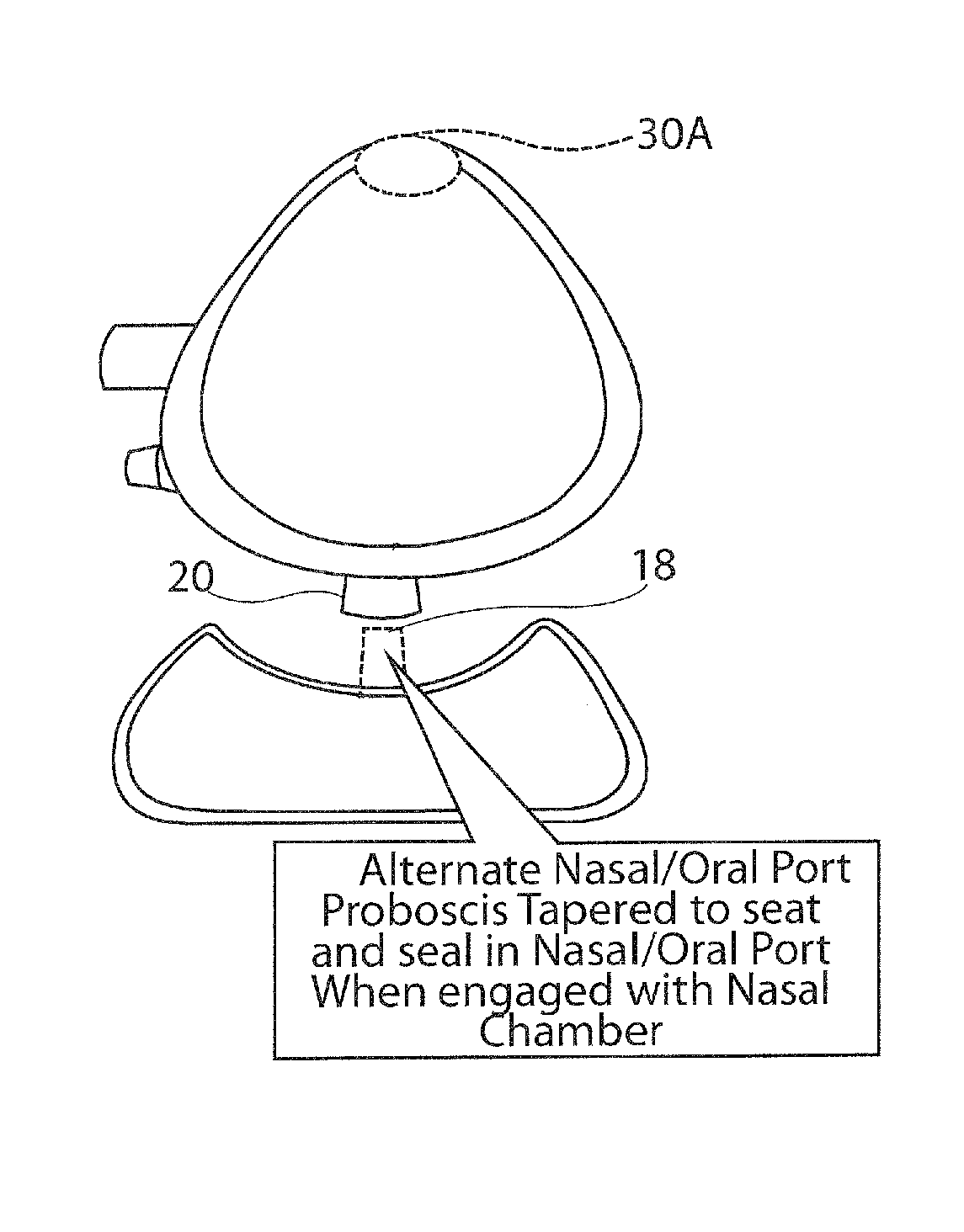
4. The method of claim 1, wherein inserting the fluid passage of the oral chamber into the at least one opening comprises inserting a proboscis tube of the oral chamber into the at least one opening.
5. The method of claim 1, comprising separating the oral chamber from the nasal mask to seal the septum or valve.
6. The method of claim 1, wherein the nasal mask comprises a ventilation port and an oxygen port, and wherein the oxygen port is separate from the ventilation port.
7. The method of claim 1, wherein flowing a gas into the nasal mask comprises providing the same pressure level at the nasal mask and the oral chamber.
8. The method of claim 1, wherein the fluid passage is formed of a flexible material.
9. The method of claim 8, further comprising moving the oral chamber relative to the nasal mask.
10. A method of ventilating a patient, comprising: applying a nasal mask over the patient's nose while leaving the patient's mouth uncovered, wherein the nasal mask having at least one opening, the at least one opening comprising a septum or valve therein, a closing of the septum or valve is actuated by pressure within the mask, and wherein the nasal mask further comprises a ventilation and/or oxygen port, wherein the at least one opening is adapted to receive a fluid passage of an oral chamber; flowing a gas into the nasal mask through the ventilation and/or oxygen port to pressurize the nasal mask; and when the nasal mask is applied over the patient's nose, inserting the fluid passage of the oral chamber into the at least one opening, thereby causing the septum or valve to open and to allow fluid communication through the fluid passage between the oral chamber and the nasal mask.
11. The method of claim 10, wherein inserting the fluid passage of the oral chamber into the at least one opening comprises inserting a proboscis tube of the oral chamber into the at least one opening.
12. The method of claim 10, wherein the nasal mask comprises a ventilation port and an oxygen port, and wherein the oxygen port is separate from the ventilation port.
13. The method of claim 10 wherein flowing a gas into the nasal mask comprises providing the same pressure level at the nasal mask and the oral chamber.
Description
BACKGROUND OF THE INVENTION
During surgery a patient usually is placed under anesthesia and the most common delivery system consists of canisters containing anesthesia gases and oxygen, a system of regulating gas flow and the patient's breathing, and a device ensuring the potency of the patient's airway for breathing, oxygenation and the delivery of an anesthetic gas mixture. A mask is used to provide oxygen to the patient either before the patient is anesthetized, while the patient is anesthetized, or if the patient is sedated during the surgery or procedure. However, one of the drawbacks of mask ventilation is that it requires constant contact between the provider's hands and the patient's face to hold the mask in place and keep the patient in the sniffing position in order to ensure that oxygen and anesthetic gases do not leak out into the air and that the patient's airway remains patent. If the provider does not maintain the patient in the sniffing position, a dangerous complication known as upper airway obstruction may occur. The reason the provider needs to perform continuous mask holding and maneuvering is due to the human anatomy and physiology. When muscles of the jaw, tongue and upper airway relax due to sedatives and/or muscle relaxants given to the patient for sedation and/or anesthesia, wherein, the jaw of the patient drops and the tongue obstructs the airway resulting in snoring (partial obstruction) or apnea (complete inability for oxygen to pass via the upper airway into the lungs), the upper airway (mouth, pharynx, larynx) may become partially obstructed and possibly completely closed. Another problem exists when a provider fails to administer enough anesthesia or sedative or the anesthesia or sedative begins to wear off and the patient begins to move. This can cause the patient's airway to obstruct as well since the patient's head and neck position are no longer in the sniffing position. Patient movement during surgery also can be dangerous because it can cause the surgeon to make a mistake, particularly in eye, ear, nose, neck, head, and throat surgery.
Notwithstanding the aforesaid potential problems, the use of facemasks, whether nasal masks, which only cover the nose, or facemasks, which cover both the nose and mouth, to apply inhalational agents, such as oxygen or volatile anesthetic gases, is essentially universal in the medical field. However, up until now, nasal masks and facemasks have been used separately as either nasal masks alone or facemasks alone. A significant clinical need has emerged, where combining a nasal mask with a mouth mask into one could have a substantial impact on patient safety during both endotracheal intubation and monitored anesthesia care cases involving sedation. For example, current standard of care recommends pre-oxygenating (delivering 100% oxygen via facemask) a patient for several minutes prior to endotracheal intubation in order to fill the patient's lungs with oxygen. Also, pre-oxygenating a patient significantly lengthens the time (2-8 minutes) that patient begins to desaturate (blood-oxygen levels begin to fall to critically low levels). Exemplary of gas inhalation masks used in administering general anesthesia (GA) to a patient is that disclosed in U.S. Pat. No. 5,975,079 (Hellings et al). As indicated by this patent, an acceptable anesthesia mask should be disposable, made of transparent material, have a strap or straps to hold the mask in place, when desired, be of sufficient size to cover the patient's nose and mouth, and have a pneumatic sealing cushion, not only to promote patient comfort, but to prevent exposing the medical staff to anesthesia or other applied gas or gases. See also U.S. Pat. No. 8,336,549 B2 in which there is discussed a disposable anesthesia face mask comprising a shell member having an annular flange and a donut shaped pneumatic sealing cushion attached to the shell member annular flange. The shell member and its flange are "pear-shaped" defining a nasal portion of first transverse extent, a mouth portion of second transverse extent, and an under-the-chin engagement portion of third transverse extent, where the second transverse extent is greater than the first transverse extent and the third transverse extent is greater than the second transverse extent.
Other prior art anesthesia masks and CPAP masks are described in U.S. Pat. No. 5,738,094; US 2014/0083425; US 2003/0024533; U.S. Pat. No. 6,779,524; US 2014/0076311; U.S. Pat. Nos. 8,001,968, 6,112,746; 8,528,558; 7,178,524; 7,036,508; 5,560,354; US 2015/0059759; and U.S. Pat. No. 5,243,971
Furthermore, mask straps and harnesses are commonly used to hold masks on a patient. However, a common problem in the majority of cases today with the use of currently available mask straps and/or the head harness is that they still require the provider to hold and maneuver the mask continuously during the surgery because there is no way of fixing patient's head and neck to a surface. U.S. Pat. No. 6,981,503 B1 (hands-free anesthesia mask) proposes a way of attaching a head strap to the face; however, it does not provide a means of restricting head and neck movement. Many times when the patient is relaxed with sedation and anesthesia the head falls forward, causing collapse of the airway. One way to solve this problem is to fix the patients face mask or head to a base surface which will prevent it from falling forward. Also, to avoid partial and/or complete obstruction the provider can perform a maneuver called the "jaw thrust" maneuver. The "jaw thrust" maneuver" is done with one hand moving the jaw up and forward to move the tongue so that the airway is opened. The "jaw thrust" is performed while holding a mask over the patient's mouth and nose to deliver oxygen. In order to ventilate the patient while performing a "jaw thrust" the provider is required to hold the mask over the patient's face almost constantly and prevents the ability to perform other tasks during the surgery. This has led to a significant loss of popularity of the mask anesthetics and the increased use of other airway devices, which are more invasive and have greater potential side effects and complications. Also, a problem exists that when a mask is adjusted on a patient when in a sniff position, when the patient's head is moved to a more natural or "vertical" position, e.g., post operation, the mask becomes loose on the patient's head. See also U.S. Pat. Nos. 6,439,231; 6,003,511; 5,983,896; 5,778,872; 4,265,235; 5,404,873; 3,856,051; 3,556,097; 4,007,737; 4,188,946; 4,265,235; 4,463,755; 4,232,667; 4,596,246; 5,121,746; 5,284,160; 5,778,872; and U.S. Pat. No. 6,129,082; U.S. 2003/0183232 A1; U.S. Pat. Nos. 3,815,596; 5,462,050; 6,035,852; 6,412,488; 6,736,139; 6,792,943; 6,981,503; 7,753,051 6,981,503 B1; 7,753,051; U.S. 2009/0178680; U.S. Pat. Nos. 4,905,712; 3,889,668; 3,897,777; US 2007/0295335.
In our co-pending PCT Application Serial No. PCT/US14/44934, we provide an improved mask strap system for an anesthesia mask that allows hands-free patient ventilation while maintaining the patient in the sniffing position and preventing head and neck movement. We also provide an anesthesia strap system for maintaining an anesthesia face mask on the head of the user, that prevents movement of the patient's head and neck, and can be placed in front of the patient's face. Therefore if the patient is already lying down, sedated, or anesthetized, the provider will not have to lift the patient's head off the table. We also provide an anesthesia mask anchor ring system including a plurality of elastomeric cords connecting the mask anchoring to a support.
SUMMARY OF THE INVENTION
The present invention provides improvements over the foregoing and other prior art, and helps to solve the problem of patient's desaturating by maintaining ventilation even during intubation. The present invention in one aspect provides a gas ventilation mask comprising an anesthesia nasal mask and a mouth or oral mask defining respectively a nasal chamber and an oral chamber, detachably connected to one another so that the nasal mask may be used either separately as a nasal mask, or together with the mouth mask as a combination nasal-mouth mask.
In another aspect of the invention, the mask is characterized by one or more of the following features:
(a) wherein the nasal and oral chambers are connected to one another through a self-closing valve or passage, preferably a septum or duck valve or passage;
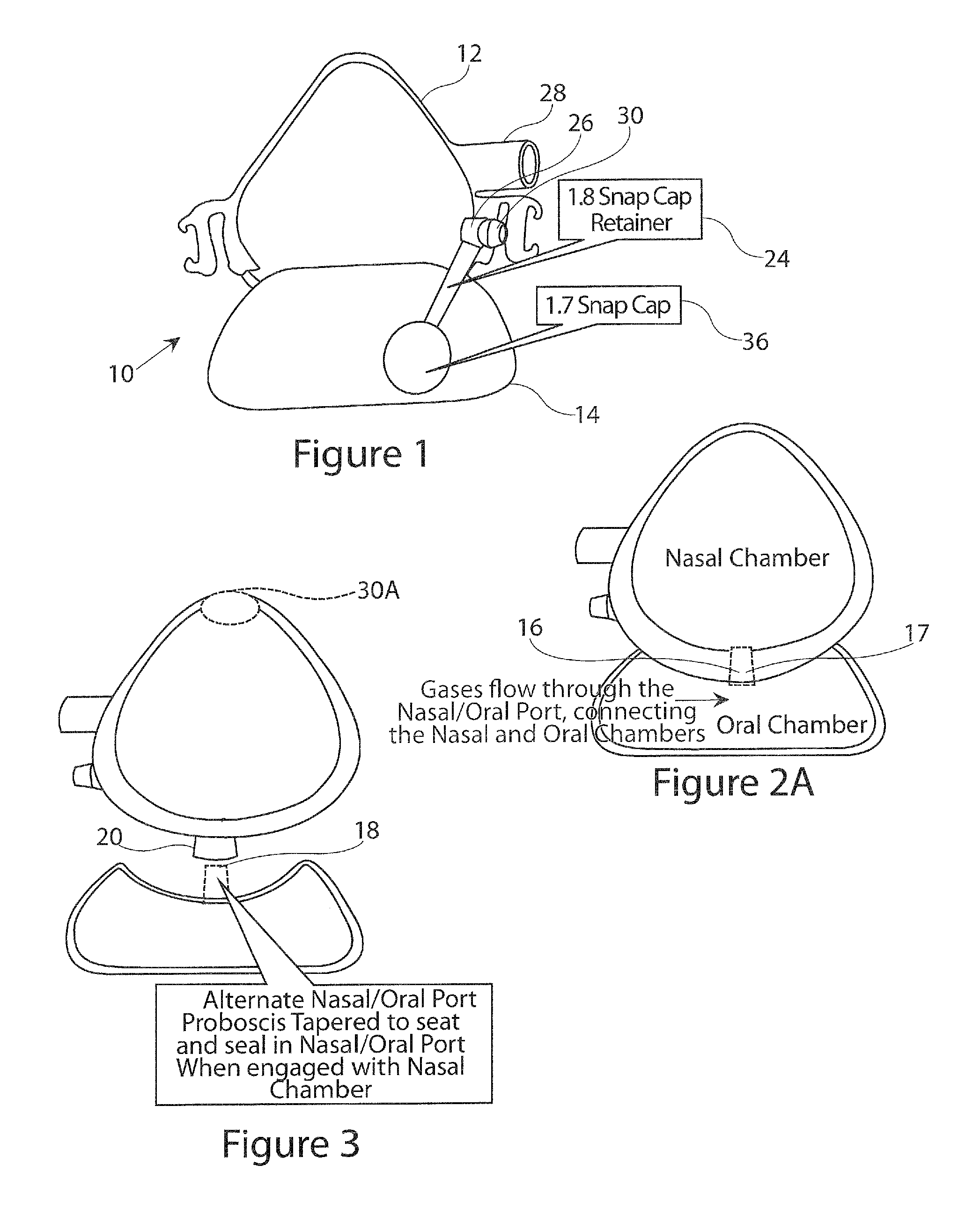
(b) further including at least one ventilation or oxygen port communicating with the nasal chamber, wherein at least one of the ventilation or oxygen port preferably is offset to a side of the nasal chamber;
(c) comprising both a ventilation port and an oxygen port communicating with the nasal chamber, wherein at least one of the ventilation port and/or the oxygen port preferably is offset to a side of the nasal chamber, and further comprising a removable stopper or cap for at least one of the ports;
(d) wherein the mask is formed at least in part of a transparent material to permit visualization of condensation or aspiration;
(e) further comprising a multi-lobed, preferably Y-shaped seal that interfaces with the patient's face and the oral and/or nasal ventilation chambers of the mask;
(f) further comprising a J-shaped seal, connected to the oral chamber that seals the oral chamber and nasal chamber interface when the two chambers are engaged, preventing gas from escaping through that interface;
(g) further comprising a multi-lobed, preferably Y-shaped seal on the nasal chamber that over-laps the J-shaped seal of the oral chamber, preventing gas from escaping that interface when both chambers are pressured;
(h) further comprising a mask strap anchor pair that has one closed side for accommodating a strap attached and an open side, or two open sides, wherein the open side or sides allows a care provider to attach the strap to a patient, wherein the open side or sides preferable are oriented up so that when strap tension force is applied, the force is resisted by a bottom portion of the strap anchor in order that the strap does not slide off the anchor; and
(i) further comprising grip indents on the left and right surfaces of the oral chamber for gripping by a care provider in placing the mask onto a patient's face.
In another aspect of the invention, the mask comprises a nasal cushion including a nasal bridge region, a check region, and an upper lip region, and a mouth cushion including a lower lip region, a cheek region, and an upper lip region; a first nasal membrane or seal comprising a substantially triangularly shaped frame of resiliently deformable material having a first molded inwardly curved rim of the first nasal membrane or seal; a second nasal membrane or seal of resiliently deformable material, the second nasal membrane or seal being thinner, as thin, or thicker than the first nasal membrane or seal, the second nasal membrane or seal having a second molded inwardly curved rim, the second nasal membrane or seal curved rim spaced a first distance from the first nasal membrane or seal curved rim in the cheek region and the second nasal membrane or seal curved rim spaced a second distance from the first nasal membrane or seal curved rim in the nasal bridge region, the second distance being greater than the first distance. The first and second distances being measured when the mask is not in use. A portion of the second membrane or seal curved rim forms a face contacting seal. A first mouth membrane or seal comprises a substantially oval shaped frame of resiliently deformable material having a first molded inwardly curved rim of the first mouth membrane or seal; a second mouth membrane or seal of resiliently deformable material, being thinner, as thin, or thicker than the first mouth membrane or seal, has a second molded inwardly curved rim. The second mouth membrane or seal curved rim is spaced a third distance from the first mouth membrane or seal curved rim in the cheek region and the second mouth membrane or seal curved rim is spaced a fourth distance from the first mouth membrane or seal curved rim in the mouth region. The fourth distance is greater than the third distance, the third and fourth distances being measured when the mask is not in use, a portion of the second membrane or seal curved rim forming a face contacting seal.
In still yet another aspect of the invention, the mask as above described is characterized by one or more of the following features:
(a) wherein the second molded rim and the first molded rim have a co-located notch to accommodate the bridge of a wearer's nose; wherein the first nasal membrane or seal molded rim and the second nasal membrane or seal molded rim preferably are substantially saddle-shaped, wherein the second nasal membrane or seal preferably is shaped so that the seal portion, in use, contacts at least the wearer's nose; and, wherein the seal portion, in use, preferably contacts the wearer's facial tissue around the sides and over the bridge of the wearer's nose, and between the base of the wearer's nose and the top wearer's lip;
(b) wherein the second rim and seal portion are shaped to generally match facial contours of the wearer in the region of facial tissue around the sides and over the bridge of the wearer's nose, and between the base of the wearer's nose and the wearer's upper lip;
(c) wherein the first and second nasal membranes or seals comprise single molded pieces;
(d) wherein the first molded inwardly curved rim of the first nasal membrane or seal is as thick, less thick, or thicker than the second nasal membrane or seal; and
(e) wherein the second molded inwardly curved rim of the second nasal membrane or seal is as thick, less thick, or thicker than the first nasal membrane or seal.
In a still further aspect of the invention the mask includes a mask body for connection with a supply of breathable gas; and a nasal cushion secured to the mask body, the mask body and the cushion forming a nose-receiving cavity. The cushion includes: a nasal bridge region, a cheek region and an upper lip region; and a substantially triangularly-shaped first nasal membrane or seal of resiliently deformable material is provided having a first molded inwardly curved rim to surround wearer's nose. A second nasal membrane or seal also formed of resiliently deformable material is provided. The second membrane or seal is relatively more flexible than the first nasal membrane or seal. The second nasal membrane or seal has a second molded inwardly curved rim, the second molded rim being of the same general shape as the first molded rim and being fixed to and extending away from the first nasal membrane or seal so as to have a second nasal membrane or seal inner surface spaced a first distance from an outer surface of the first molded rim in the wearer's cheek region. The second membrane or seal inner surface is spaced a second distance from the first nasal membrane or seal outer surface of the first molded rim in the nasal bridge region. The second distance is greater than the first distance, when the first and second distances are measured when the mask is not in use. A portion of the second molded rim forms a face contacting seal, wherein the portion preferably is substantially coterminous with respect to said second molded rim and is resiliently deformable towards said first nasal membrane or seal.
In another aspect of the invention, the mask is characterized by one or more of the following features:
(a) the second membrane or seal molded rim and the first nasal membrane or seal molded rim preferably each have a co-located notch to accommodate the bridge of a wearer's nose. The first and second molded rims preferably are substantially saddle-shaped. The second nasal membrane or seal preferably is shaped so that the seal portion, in use, contacts at least the wearer's nose. And, wherein the seal portion, in use, contacts the wearer's facial tissue around the sides and over the bridge of the wearer's nose, and between the base of the wearer's nose and the wearer's upper lip of the wearer; and
(b) wherein the rim and the seal portion are shaped to generally match facial contours in the region of facial tissue around the sides and over the bridge of the wearer's nose, and between the base of the nose and the upper lip of the wearer.
The present invention also provides a nasal CPAP treatment apparatus and a oral/nasal full face mask comprising: a generator, ventilator or O.sub.2 source for the supply of gas at a pressure elevated above atmospheric pressure; a gas delivery conduit coupled to the generator; and a nasal mask or a full face mask that comprises a nasal cushion including a nasal bridge region, a cheek region, and an upper lip region, and a mouth cushion including a lower lip region, a cheek region, and an upper lip region; a first nasal membrane or seal comprising a substantially triangularly shaped frame of resilient material having a first molded inwardly curved rim of the first nasal membrane or seal; a second nasal membrane or seal of resilient material, said second nasal membrane or seal being thinner, as thin, or thicker than the first nasal membrane or seal. The second nasal membrane or seal has a second molded inwardly curved rim, the second nasal membrane or seal curved rim being spaced a first distance from the first nasal membrane or seal curved rim in the cheek region and the second nasal membrane or seal curved rim being spaced a second distance from the first nasal membrane or seal curved rim in the nasal bridge region. The second distance is greater than the first distance, the first and second distances being measured when the mask is not in use. A portion of the second membrane or seal curved rim forms a face contacting seal. A first mouth membrane or seal comprises a substantially oval shaped frame of resiliently deformable material having a first molded inwardly curved rim of the first mouth membrane or seal; a second mouth membrane or seal of resilient material, the second mouth membrane or seal being thinner, as thin, or thicker than the first mouth membrane or seal, the second mouth membrane or seal having a second molded inwardly curved rim. The second mouth membrane or seal curved rim is spaced a third distance from the first mouth membrane or seal curved rim in the cheek region and the second mouth membrane or seal curved rim being spaced a fourth distance from the first mouth membrane or seal curved rim in the mouth region. The fourth distance is greater than the third distance, the third and fourth distances being measured when the mask is not in use, a portion of the second membrane or seal curved rim forming a face contacting seal.
In another aspect of the invention, the CPAP as above described is characterized by one or more of the following features:
(a) wherein the first and second molded rims preferably each have a co-located notch to accommodate the bridge of a wearer's nose. The first and second molded rims preferably are substantially saddle-shaped. The second nasal membrane or seal preferably is shaped so that the seal portion, in use, contacts at least the wearer's nose. The seal portion, in use, contacts the facial tissue around the sides and over the bridge of the nose, and facial tissue around the sides and over the bridge of the nose, between the base of the nose and the upper lip and between the base of the nose and the upper lip of the wearer;
(b) wherein the second molded rim and the seal portion are shaped to generally match facial contours in the region of facial tissue around the sides and over the bridge of the wearer's nose, between the base of the wearer's nose and the wearer's upper lip and between the base of the wearer's nose and the wearer's upper lip of the wearer. The second molded rim and the first molded rim preferably have a co-locating rim to accommodate the lips of a wearer's mouth. The first mouth membrane or seal molded rim and the second mouth membrane or seal molded rim preferably are substantially oval shaped. The second mouth membrane or seal preferably is shaped so that the seal portion, in use, contacts at least a wearer's upper and lower lip, and also preferably contacts the facial tissue around the sides and over the upper and lower lips of the mouth of the wearer. The second rim and seal portion preferably are shaped to generally match facial contours in the region of facial tissue around the sides and over the upper and lower lip of the mouth of the wearer. The first and second mouth membranes or seals preferably comprise one molded pieces, wherein the first molded inwardly curved rim of the first mouth membrane or seal preferably is as thick, less thick, or thicker than the second mouth membrane or seal, and wherein the second molded inwardly curved rim of the second mouth membrane or seal preferably is as thick, less thick, or thicker than the first mouth membrane or seal.
The present invention also provides a mask for connection to a wearer's face comprising: a mask body for connection to a supply of breathable gas; and a mouth cushion secured to said mask body. The mask body and cushion form a mouth-receiving cavity. The cushion includes: a mouth region, a cheek region and an upper and lower lip region. A substantially oval-shaped first mouth membrane or seal of resilient material has a first molded inwardly curved rim to surround the wearer's mouth; a second mouth membrane or seal also formed of resiliently deformable material, the second mouth membrane or seal being relatively more flexible than the first mouth membrane or seal. The second mouth membrane or seal has a second molded inwardly curved rim, the second molded rim being of the same general shape as the first molded rim and fixed to and extending away from the first mouth membrane or seal so as to have a second mouth membrane or seal inner surface spaced a first distance from an outer surface of the first molded rim in the check region. The second mouth membrane or seal inner surface is spaced a second distance from the first mouth membrane or seal outer surface of the first molded rim in the mouth region. A portion of the second molded rim forms a face contacting seal. The seal portion is substantially coterminous with respect to the second molded rim and is resiliently deformable towards the first mouth membrane or seal in use of the mask.
In another aspect of the invention, the aforesaid mask is characterized by one or more of the following features:
(a) the second membrane or seal molded rim and the first mouth membrane or seal molded rim preferably each have a co-located rim to accommodate the wearer's mouth. The first and second molded rims preferably are substantially oval-shaped. The second mouth membrane or seal preferably is shaped so that the seal portion, in use, contacts at least the wearer's mouth. The seal portion, in use, preferably contacts the facial tissue around the sides and over the wearer's mouth, and between the wearer's upper and wearer's lower lip, wherein said rim and said seal portion preferably are shaped to generally match facial contours in the region of facial tissue around the sides and the wearer's mouth, and between the wearer's upper and wearer's lower lip.
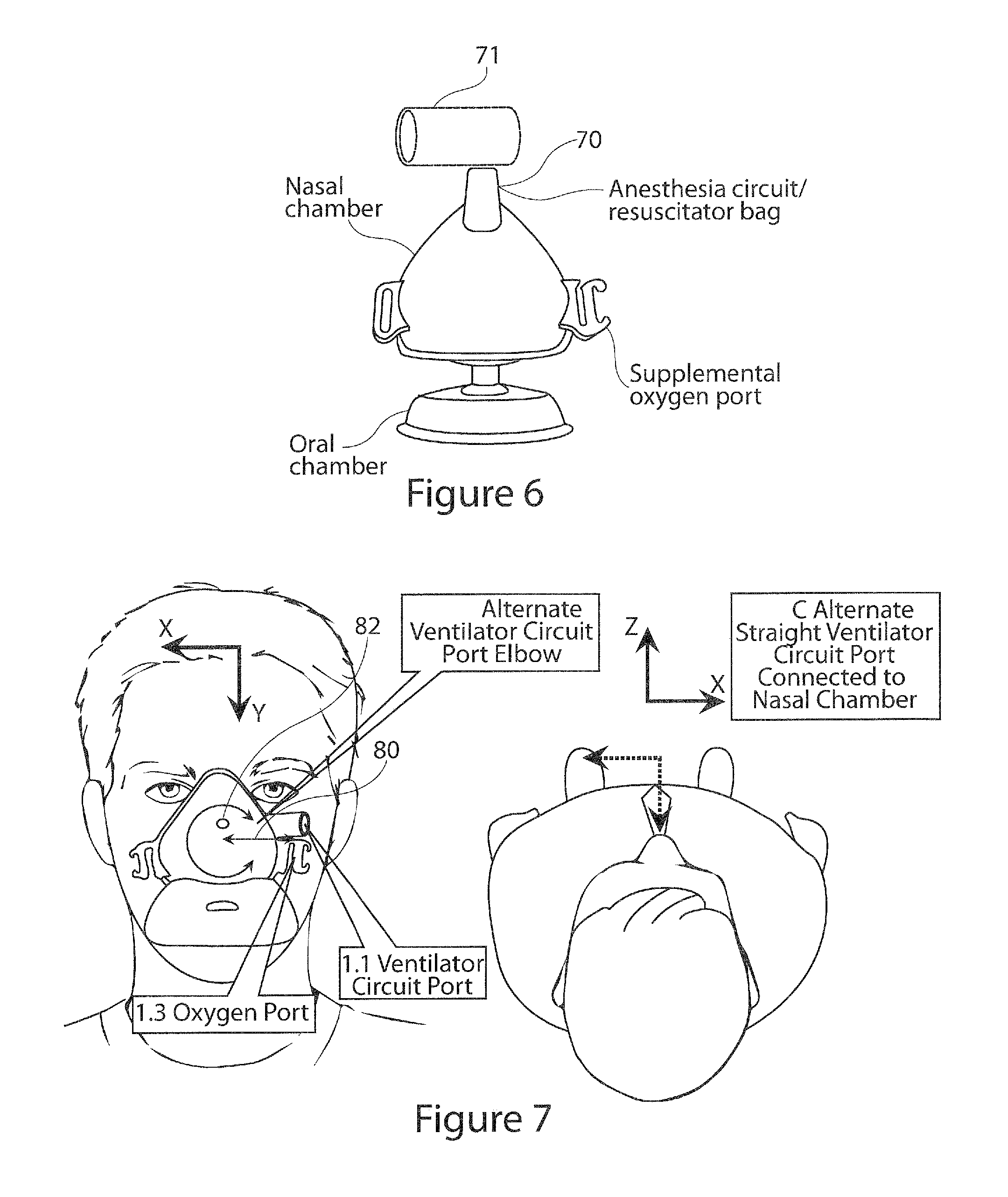
(b)(1) Optionally, the mask has a ventilator circuit port, projecting from a side of the nasal chamber as a straight port nominally located in an X-Y plane located on a left side of the patient projecting in a negative X direction or essentially parallel to the X axis, wherein the angle of the port relative to the X axis preferably projects at an angle that varies from plus 90 degrees to negative 90 degrees.
(b)(2) Optionally, the mask has a ventilator circuit port projecting from a side of the nasal chamber as a straight port nominally located in an X-Y plane located on the right side of the patient projecting in the positive X direction or essentially parallel to the X axis, wherein the angle of the port relative to the X axis preferably projects at an angle that varies from plus 90 degrees to negative 90 degrees.
(b)(3) Optionally, the mask has a straight ventilator circuit port that is at an angle nominally located in the X-Y plane, wherein the ventilator circuit port preferably projects to an angle out of that plan by plus 90 degrees to negative 90 degrees.
(b)(4) Optionally, the mask has an alternate ventilator circuit port, projecting from a top of the nasal chamber in the negative Y direction as an elbowed port nominally located in the X-Y plane, wherein an open end of the elbow that connects with the ventilator points to a right side of the patient projecting in a positive X direction or essentially parallel to the X axis, wherein the angle of the elbowed port relative to the X axis preferably projects at an angle that varies from plus 90 degrees to negative 90 degrees.
(b)(5) Optionally, the mask has an alternate ventilator circuit port, projecting from a top of the nasal chamber in the negative Y direction as an elbowed port nominally located in the X-Y plane, wherein an open end of the elbow that connects with the ventilator points to a left side of the patient projecting in a negative X direction or essentially parallel to the X axis, wherein the angle of the elbowed port relative to the X axis preferably projects at an angle that varies from plus 90 degrees to negative 90 degrees, wherein the angle of the elbow portion of the alternate ventilator circuit port, preferably also projects at an angle out of the plane by plus 90 degrees to negative 90 degrees.
(b)(6) Optionally, the mask has an oxygen port projecting from a side of the nasal chamber as a straight port nominally located in an X-Y plane located on a left side of the patient projecting in the negative X direction that can be parallel to the X axis, wherein the angle of the port relative to the X axis preferably projects at an angle that varies from plus 90 degrees to negative 90 degrees.
(b)(7) Optionally, the mask has an oxygen port projecting from the side of the nasal chamber as a straight port nominally located in an X-Y plane located on a right side of the patient projecting in the positive X direction that can be parallel to the X axis, wherein the angle of the port relative to the X axis preferably projects at an angle that varies from plus 90 degrees to negative 90 degrees.
(b)(8) Optionally, the mask has an oxygen port, projecting from a top of the nasal chamber in a negative Y direction as an elbowed port nominally located in an X-Y plane, wherein the open end of the elbow that connects with the ventilator points to a right side of the patient projecting in the positive X direction that can be parallel to the X axis, wherein the angle of the elbowed port relative to the X axis preferably projects at an angle that varies from plus 90 degrees to negative 90 degrees.
(b)(9) Optionally, the mask has an oxygen port projecting from a top of the nasal chamber in a negative Y direction as an elbowed port nominally located in an X-Y plane, wherein the open end of the elbow that connects with the ventilator points to a left side of the patient projecting in the negative X direction that can be parallel to the X axis, wherein the angle of the elbowed port relative to the X axis preferably projects at an angle that varies from plus 90 degrees to negative 90 degrees.
(b)(10) Optionally, the mask has an alternate ventilator circuit port projecting from a front of the nasal chamber in the positive Z direction as an elbowed port, wherein an open end of the elbow that connects with the ventilator is pointing to a left side of the patient projecting in a negative X direction or essentially parallel to the X axis, nominally in the X-Y plane, wherein the angle of the elbowed port relative to the X axis preferably projects at an angle that varies from plus 180 degrees to negative 180 degrees, or wherein the angle of the elbow portion of the alternate ventilator circuit port, that is nominally located in the X-Y plane also preferably projects at an angle out of that plane by plus 90 degrees to negative 90 degrees.
(b)(11) Optionally, the mask has an oxygen port, projecting from a front of the nasal chamber in a positive Z direction as an elbowed port, wherein an open end of the elbow that connects with the ventilator points to s left side of the patient projecting in a negative X direction or essentially parallel to the X axis, nominally in the X-Y plane, wherein the angle of the elbowed port relative to the X axis preferably projects at an angle that varies from plus 180 degrees to negative 180 degrees, or wherein the angle of the oxygen port elbow portion that is nominally located in the X-Y plane preferably also projects to an angle out of that plane by plus 90 degrees to negative 90 degrees.
(b)(12) Optionally, the mask has a ventilator circuit port projecting from a side of the Nasal Chamber as a straight port nominally located in a Y plane located in a center side of the patient projecting in the negative y direction.
(b)(13) Optionally, the mask has an oxygen port projecting from a side of the nasal chamber as a straight port nominally located in a X-Y plane located on a left side of the patient projecting in the negative X direction or essentially parallel to the X axis, wherein the angle of the port relative to the X axis projects at an angle that varies from plus 90 degrees to negative 90 degrees.
(b)(14) Optionally, the mask has an alternate ventilator circuit port projecting from a front of the nasal chamber in a positive Z direction as an elbowed port, wherein the elbow has an ability to swivel 360 degrees about the Z axis of the straight port connected to the nasal chamber, wherein the swivel elbow preferably is nominally a 90 degree elbow.
(b)(15) Optionally, the mask has a straight ventilator port connected to the nasal chamber in any location.
(b)(16) Optionally, wherein the nasal chamber of the mask is configured with one or more ventilator circuit ports and zero or one or more oxygen ports.
(b)(17) Optionally, wherein nasal chamber of the mask is designed to operate under a positive gauge pressure relative to the ambient atmosphere at a pressure less than or equal to 90 cm of water.
(b)(18) Optionally, wherein the nasal and oral chambers of the mask, when connected, are designed to operate under a positive gauge pressure relative to the ambient atmosphere at a pressure less than or equal to 90 cm of water.
(b)(19) Optionally, the nasal chamber is designed to operate under a negative gauge pressure relative to the ambient atmosphere at a pressure greater than or equal to negative 10 pounds of force per square inch.
(b)(20) Optionally, the nasal and oral chambers, when connected, are designed to operate under a negative gauge pressure relative to the ambient atmosphere at a pressure greater than or equal to 10 pounds of force per square inch.
In yet another embodiment of the invention there is provided a nasal mask comprising a ventilation port, an O.sub.2 port and a cap or plug interchangeable between the ventilation port and the O.sub.2 port.
The present invention in yet another aspect provides improvements in devices for holding a mask in position on a patient, and in another aspect for holding a patient's head in position. More particularly, in one aspect of the invention, there is provided a mask anchor for holding a face mask on a patient, comprising a head bonnet for engaging a back of a patient's head, a posterior head strap that originates from behind the patient's head, in contact with the patient's head and attaches either directly or indirectly to the mask when the mask is on the patient's face, wherein the strap can be tightened to create a seal to allow for positive pressure ventilation or left loose and for providing supplement oxygen.
In another embodiment the mask anchor may include one or more straps for attachment to a base/surface, for securing the mask to the patient's face and also for securing the patient's head to the base/surface and for stabilizing the patient's head in position.
In another embodiment, the mask anchor comprises three straps, a first side strap, a second side strap and a third side strap approximately evenly spaced from and joined to the first strap and the second strap, and positioned posteriorly.
In one embodiment the posterior head strap is attached directly to the mask, or the first and second straps are attached directly to the mask.
In yet another embodiment, the posterior head strap is attached to an anchor ring which in turn is placed on the mask, or the first and second side straps attach to a mask anchor ring which is placed over the mask.
The present invention also provides a mask strap system including an expandable strap portion, having the ability to extend up to twice its length or more when the patient is in a sniff position, so as to maintain tension on the mask when the patient is placed in a natural or "vertical" position.
In one embodiment the anesthesia mask strap system comprises an expandable strap portion having the ability to extend; second and third non-expandable strap sections fixed to ends of the expandable strap section; and an adhesion section or device for fixing a length of the strap system when the second and third non-expandable strap sections are pulled to tension the expandable strap section. Preferably, the expandable strap section has the ability to extend up to twice its length, or more, and is formed of a resiliently expandable elastic material.
In yet another aspect of the mask strap system, the second and third non-expandable strap sections are fixed by adhesion to themselves. In such aspect the adhesion comprises hook and loop fasteners, or a mechanical clasp, such as a gripper, a suspender-type no-slip clasp, a button and buttonhole, or a tab and belt hole.
In another and preferred aspect of the mask strap system, the strap system length is fixed by folding the second and third non-expandable strap sections back on themselves.
In still yet another embodiment of the mask strap system, the second and third non-expandable strap sections are fixed to a patient head support or a table supporting the patient.
The present invention also provides an anesthesia mask having a strap system as above described.
The present invention also provides an anesthesia mask comprising an anesthesia nasal mask and a mouth mask defining respectively a nasal chamber and an oral chamber, detachably connected to one another so that the nasal mask may be used either separately as a nasal mask, or the nasal mask and the mouth mask used together as a combination nasal-mouth mask. The anesthesia mask preferably has two sets of retention straps, each comprising a first expandable strap portion having the ability to extend and second and third non-expandable portions fixed to ends of the first expandable strap portions, respectively and an adhesive section or device for fixing a length of the strap system when the second and third non-expandable strap sections are pulled to tension the expandable strap section, attached respectively to the nasal chamber and the oral chamber. In a preferred embodiment, the adhesion section comprises hook and loop fasteners.
With the current invention, the combined nasal mask and oral mask, can be used together as a facemask to ventilate a patient either prior to endotracheal intubation or during general anesthesia (GA), or the mouth mask can be separated from the nasal mask and the nasal mask used to apply continuous positive airway pressure (CPAP) to help maintain a patent airway and ventilate a patient while the anesthesiologist attempts intubation, which will significantly prolong the time until the patient begins to desaturate. The current invention also is useful during sedation cases, especially for deep sedation or for patients with Obstructed Sleep Apnca (OSA) or obesity, where the upper airway of many of these patients becomes obstructed and prevents or impedes breathing. The mouth mask of the current invention also can be separated from the nasal mask and the nasal mask can be used to apply continuous positive airway pressure (CPAP) to help relieve the upper airway obstruction, maintain a patent airway, and assist in ventilation during the case. The combined nasal and mouth mask of the current invention also is useful in situations where a nasal mask is not sufficient to ventilate the patient. With the mask of the present invention one can reattach the mouth mask and the mask used for traditional bag-mask ventilation. The mask of the present invention also permits a health care provider to apply nasal CPAP during semi-awake fiberoptic intubations, where being able to maintain a patient's oxygen saturation levels may be critical, or to apply PEEP to mechanically ventilated patients. Yet another feature and advantage of the mask of the present invention over the prior anesthesia mask art is the ability to secure not only the combined nasal mask and mouth mask to the patient's face allowing for hands-free ventilation, but also to secure the patient's head and neck in place by attaching to a surface and maintaining the patient in a position that ensures a patent airway, which is critical for oxygenation and ventilation.
BRIEF DESCRIPTION OF THE DRAWINGS
Further features and advantages of the present invention will be seen from the following detailed description, taken in conjunction with the accompanying drawings, wherein like numerals depict like parts, and wherein:
FIG. 1 is a front view of a combined nasal mask and oral mask in accordance with the present invention;
FIG. 2A is a rear view of the mask of FIG. 1;
FIGS. 2B-2D show details of the duck valve portion of the nasal mask chamber of FIG. 1;
FIG. 2E shows details of the oral mask chamber of FIG. 1;
FIG. 3 is an exploded view of the mask of FIG. 1;
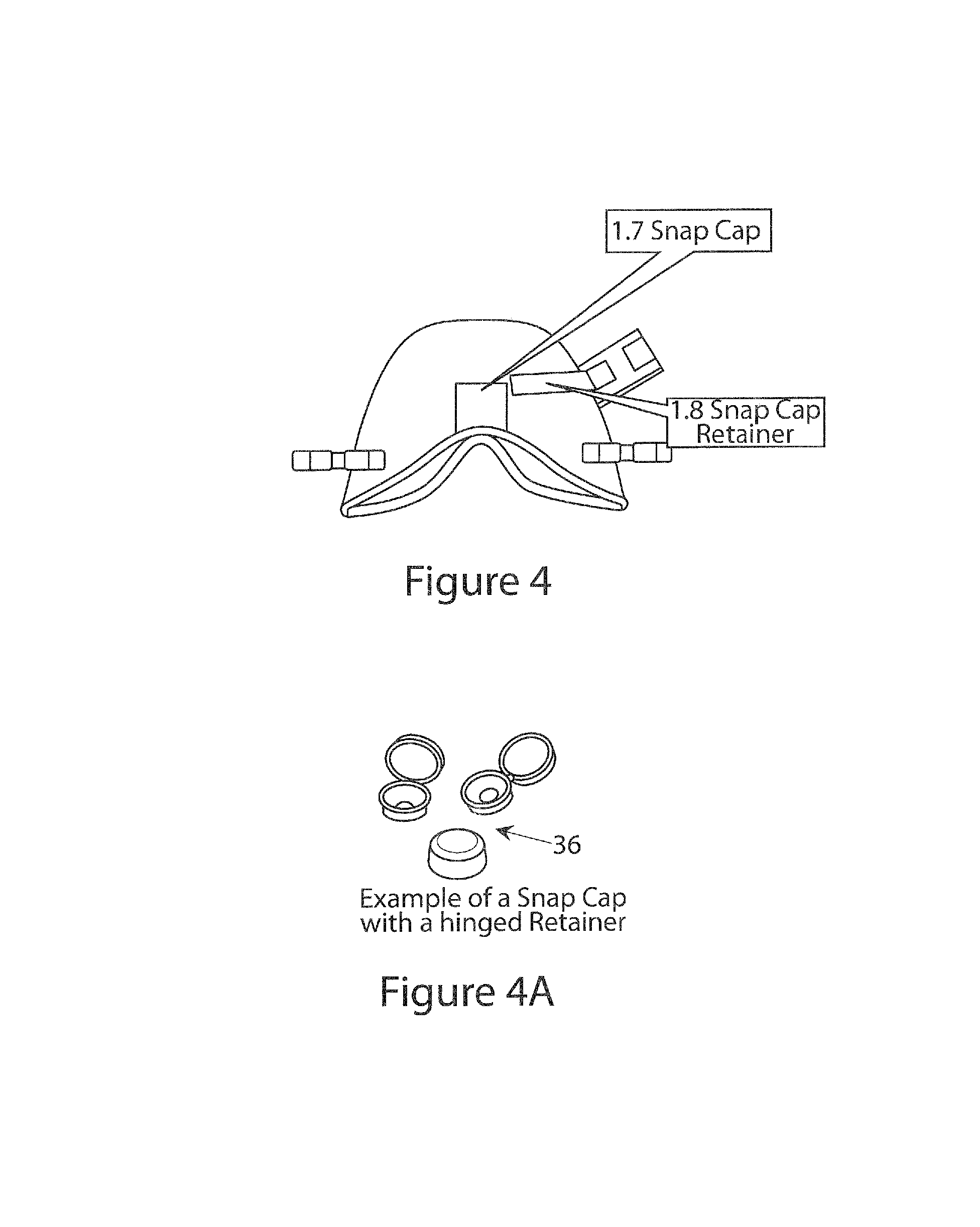
FIG. 4 is a bottom view of the nasal chamber portion of the mask of FIG. 1;
FIG. 4A is a perspective view of snap caps for use with the mask;
FIG. 5 is a perspective view of the nasal chamber portion of FIG. 1;
FIG. 6 is a view similar to FIG. 1 of an alternative embodiment of mask in accordance with the present invention;
FIG. 7 is a view similar to FIG. 1 of another alternative embodiment of mask in accordance with the present invention;
FIG. 8A is an exploded view from the interior of a combined nasal mask and oral mask in accordance with the present invention;
FIG. 8B is an exploded side elevational view of a combined nasal mask and oral mask in accordance with the present invention;
FIG. 8C is an exploded front view of a combined nasal mask and oral mask in accordance with the present invention;
FIG. 9A is an interior view of a combined nasal mask and oral mask in accordance with the present invention;
FIG. 9B is a side elevational view of a combined nasal mask and oral mask in accordance with the present invention;
FIG. 9C is a plan view of combined nasal mask and oral mask in accordance with the present invention;
FIGS. 9D and 9E are enlarged views of a J-shaped seal element of the combined nasal mask and oral mask in accordance with the present invention;
FIG. 9F is an enlarged view of a "Y" seal of a combined nasal mask and oral mask in accordance with the present invention;
FIG. 10 is a side elevational view showing a combined nasal mask and oral mask on a patient in accordance with the present invention;
FIGS. 11A and 11B show details of the Y element of the combined nasal mask and oral mask in accordance with the present invention;
FIGS. 12A-12D show the J-shaped seal element in accordance with the present invention;
FIGS. 13A-19C are views of an alternative and preferred embodiment of combined nasal mask and oral mask in accordance with the present invention;
FIGS. 20A-C illustrate use of the nasal chamber portion of the mask for continuous positive airway pressure, and FIGS. 20D and 20E are side and end views of a cap valve useful with the nasal chamber portion of the mask of FIGS. 20A and 20B;
FIG. 21 is an end view showing a mask anchor applied to the head of a patient;
FIG. 22 is a side elevational view thereof;
FIG. 23 is a perspective view thereof;
FIG. 24A is a top-plan view of a mask anchor ring in accordance with further embodiment of the invention; FIG. 24B is a view similar to FIG. 24A showing a mask anchor ring on a mask;
FIGS. 25A and 25B depict a ventilation mask on a patient in the sniff position (FIG. 25A) and in a natural or "vertical" position (FIG. 25B);
FIGS. 26A and 26B are top plan and side elevational views, respectively of a ventilation mask strap system in accordance with the present invention;
FIG. 27A is a top plan view of a ventilation mask with a strap system in accordance with the present invention;
FIG. 27B is a side elevational view of the strap system;
FIG. 27C is an enlarged view of a portion of the strap illustrated in FIG. 27B;
FIG. 28 is a side view showing an alternative embodiment in which the mask strap is attached to a patient head support in accordance with the present invention`
FIG. 29 is a top plan view of a combined nasal and mouth ventilation mask in accordance with the present invention;
FIG. 30A and FIG. 30B are side and front views showing the mask of FIG. 29 attached to a patient; and
FIGS. 31A-31E are similar to FIGS. 20A-20E, and illustrate how a luer connector may be integrated into a cap valve for accommodating a gas monitoring line.
DETAILED DESCRIPTION OF THE INVENTION
As used herein, unless otherwise stated, the mask of the present invention advantageously may be used for delivering anesthesia, for positive pressure ventilation, CPAP, administration of supplemental oxygen, or PEEP (positive and expiratory pressure) in connection with a variety of pressurized gas sources including ventilation circuits, AMBU bags, oxygen canisters, etc.
Also, as used herein, the term "nasal mask" and "nasal chamber", and "oral mask" and "oral chamber", respectively, may be used interchangeably.
Major elements of mask 10 in accordance with the present invention are illustrated FIGS. 1-5. The primary elements of the mask are a nasal chamber 12 and an oral chamber 14. Nasal chamber 12 is the primary structural element of the mask supporting all other sub-elements of the mask as will be described below. When combined as illustrated in FIG. 1 and FIG. 2, gases from the ventilator or to the ventilator are passed through both the mouth and the nose. The mask 10 operates as a traditional full face ventilation mask in this configuration. The full mask provides gases to the patient and removes waste gas through a ventilation port of the nasal chamber which attaches to a ventilation circuit that then attaches to an anesthesia machine. Gases can be exchanged from the patient's nasal orifice and or the oral orifice of the patient. One or more duckbill valves 16 are integral to the nasal chamber 12 as shown in FIG. 2D. In this state, they seal the nasal chamber 12, preventing flow out of the valve orifices. When the distal end of the oral chamber 14 proboscis tube 18 is engaged with the duck bill valve 16 located in the nasal chamber 12, the valve is opened, allowing gas transfer between the nasal and oral chambers. A duck bill valve separated from the nasal chamber 12 but placed on the oral chamber hollow proboscis tube is shown in FIG. 2E to illustrate how the valve is opened when the proboscis tube is engaged. The seal of the nasal chamber surrounds the nose and with the duck bill valves closed, gas exchange can only occur between the nose and the ventilation port, being contained by the other elements of the chamber.
The nasal chamber 12 and oral chamber 14 of the mask are mated and connected to one another through a nasal/oral port 17 which includes a septum or duck valve 16 (FIG. 2A-2E). Alternatively, as shown in FIG. 3, nasal chamber 12 and oral chamber 14 may be mated and connected to one another through nasal/oral port 17 by a tapered proboscis 18 which extends from the oral chamber 14 and engages with a tapered port 20 in the nasal chamber 12. A snap cap 22 which may be held on a line retainer 24 or hinged to a retainer ring 26 is provided for sealing port 20 when the nasal chamber 12 and oral chamber 14 are separated from one other.
A nominal, e.g., 15 mm diameter OD ventilator port 28 in the nasal chamber 12 interfaces with an anesthesia ventilation circuit or bag-mask (not shown). A preferred orientation of the ventilator port 28 is on the left side of the mask although alternate positions could be off center or on the right side of the mask as illustrated in FIG. 6. When a patient is being transported, the ventilation port 28 remains open to the atmosphere, and allows CO.sub.2 and other gasses to escape the patient during the breathing process.
A second port 30 for introduction of oxygen is provided in nasal chamber 12, and includes a cap 32 which seals the oxygen port 30 during ventilation of the patient. Cap 32 is removed during patient transport and an oxygen supply line (not shown) is connected to the oxygen port 30, and typically past operation. The connection can be either a "Christmas Tree" type, as the preferred style, or a luer lock connection. The preferred location of oxygen port 30 is on the left side of the patient. An alternate configuration could be on the right side.
When the nasal chamber 12 and oral chamber 14 are connected, the septum valve 16, is opened by the septum valve proboscis 18. This opening allows gas flow between the nasal chamber 12 and the oral chamber 14. As noted supra, a septum or duck valve is the preferred configuration, although other valves that are open when the two chambers are connected are possible. When the two chambers are separated, the proboscis 18 is removed, the duck valve 16 closes, sealing the nasal chamber 12 and prevents flow of gas out of the nasal chamber due to ventilator pressure inside the chamber. One or more septum or duck valves can interface between the nasal chamber 12 and the oral chamber 14, although, two are a preferred configuration. Alternatively, simple caps or plugs may be used in place of the septum or duck valve(s) to seal the nasal chamber. Note that in an alternate configuration the separate oxygen port 30 may be eliminated, and the oxygen supply line could interface directly with nasal portion of the nasal/oral port 17. A snap cap interface 34 exists on the outside of oxygen port 30. During nasal ventilation, a snap cap 36 is placed over oral port 30, sealing the nasal chamber 12. When the nasal chamber 12 and oral chamber 14 are connected, the tapered nasal/oral proboscis 18 engages with the nasal/oral port 17, creating a seal to the exterior, while allowing gas flow between the nasal chamber 12 and oral chamber 14. Note that in an alternate configuration, the duck valve or septum port could be located on the oral chamber 14 and the hollow proboscis located on the nasal chamber 12.
Anchor straps 38, 40 are located on the left and right sides of the nasal chamber 12. Anchor straps 38, 40 secure the mask to a patient's head or to a patient head support device as described in our PCT application number PCT/US 14/44934, or in our U.S. Application Ser. No. 62/118,301, filed Feb. 19, 2015, the contents of which are incorporated herein by reference.
Soft interface rings 38, 39, which may be, e.g. a gel filled or air filled ring, or ring formed of a low durometer material such as foam, silicone, a low durometer thermoplastic elastomer, a low durometer thermoplastic urethane, are connected to the nasal chamber 12 and oral chamber 14, and interface the nasal chamber 12 and the oral chamber 14, respectively to the patient's face over the nose and mouth, providing near-air-tight seals, as will be described in detail.
When the nasal chamber 12 solely is being used for ventilation of a patient, the nasal/oral port is sealed it so that positive ventilation pressure can be achieved.
Use of the nasal/oral mask of the present invention will now be described. When the nasal chamber 12 and oral chamber 14 of the mask are connected as shown in FIG. 1, the mask is a full face ventilation mask. Both the nasal and oral openings of a patient's face are in communication with the ventilator circuit.
When the nasal chamber 12 and oral chamber 14 of the mask are separated as shown in FIG. 3, the mask may be used solely as a nasal ventilation mask. Providing nasal ventilation allows for oxygenation to occur even during intubation or while performing bag-mask ventilation. Note that alternate configurations of the mask could consist of the nasal chamber 12 only, with no septum valve or oral chamber being included in the configuration.
Ventilation port 28 as shown is designed to nominally fit on the inner diameter of a ventilation circuit (not shown). Alternate configurations are possible where the ventilation port 28 fits the outer diameter of the ventilation circuit. In use, ventilation port 28 is connected to a anesthesia circuit, while the oxygen port 30 is connected an O.sub.2 supply. The ventilation port 28 may be located to the top or to one side of the mask (preferably to the left side of the mask). In the FIGS. 1-5 embodiment, the oxygen port 30 is located to one side, preferably to the left side of the mask (from the anesthesiologist's viewpoint), so as to permit laryngoscopy and intubation to be viewed by the anesthesiologist from the right side of the patient's face, and not obstruct the anesthesiologist's view of the patient's oral cavity. Of course, the ventilation port 28 and oxygen port 30 may be located on the right side of the mask as well (from the anesthesiologist's viewpoint).
In another embodiment, shown in FIG. 6, a ventilation port 70 may project off center from the nasal chamber 12 as a straight port or angled to the right side of the nasal chamber (shown in phantom at 71) nominally located in the X-Y plane located on the right side of the patient, projecting in a negative X direction that can be parallel to the X axis. The angle of the port relative to the X axis can project at an angle that varies from plus 90 degrees to negative 90 degrees. In another alternative embodiment ventilation circuit port, 70, may be provided projecting from the top of the nasal chamber 12 in the negative Y direction as an elbowed port. The open end of the elbowed port 70 that connects with the ventilator may be oriented to point to the right side of the patient projecting in the positive X direction that can be parallel to the X axis. The angle of the elbowed port relative to the X axis can project at an angle that varies from plus 90 degrees to negative 90 degrees.
In still yet another embodiment ventilation port 70 may project from the top of the nasal chamber 12 in the negative Y direction as an elbowed port nominally located in the X-Y plane. In such embodiment, the open end of the elbow that connects with the ventilator points to the left side of the patient projecting in the negative X direction that can be parallel to the X axis. Additionally the angle of the elbowed port relative to the X axis can project at an angle that varies from plus 90 degrees to negative 90 degrees.
The angle of the elbow portion of the alternate ventilation port, 70 that is nominally located in the X-Y plane also can project to an angle out of that plane by plus 90 degrees to negative 90 degrees.
Oxygen port 30 may project from the side of the left nasal chamber as a straight port nominally located in the X-Y plane located on the left side of the patient projecting in the negative X direction that can be parallel to the X axis. The angle of oxygen port 30 relative to the X axis can project at an angle that varies from plus 90 degrees to negative 90 degrees. Oxygen port 30 may project from the side of the nasal chamber 12 as a straight port nominally located in the X-Y plane located on the right side of the patient projecting in the positive X direction that can be parallel to the X axis. Additionally the angle of the oxygen port 30 relative to the X axis can project at an angle that varies from plus 90 degrees to negative 90 degrees. Oxygen port 30 also may project from the top of the nasal chamber 12 in the negative Y direction as an elbowed port nominally located in the X-Y plane. The open end of the elbow that connects with the ventilator points to the right side of the patient projecting in the positive X direction that can be parallel to the X axis. Additionally the angle of the elbowed port relative to the X axis can project at an angle that varies from plus 90 degrees to negative 90 degrees.
Oxygen port 30 also may project from the top of the nasal chamber in the negative Y direction as an elbowed port nominally located in the X-Y plane as shown in phantom in FIG. 3 at 30A. The open end of the elbow that connects with the ventilator is pointing to the left side of the patient projecting in the negative X direction that can be parallel to the X axis. Additionally the angle of the elbowed port relative to the X axis can project at an angle that varies from plus 90 degrees to negative 90 degrees.
Yet another alternative is shown in FIG. 7, where the ventilation port 80 projects from the front of the nasal chamber 12 in the positive Z direction as an elbowed port which, in a preferred embodiment is swivel mounted. The open end of the elbow that connects with the ventilator points to the left side of the patient projecting in the negative X direction that can be parallel to the X axis as shown in FIG. 13, nominally in the X-Y plane. Additionally the angle of the elbowed port relative to the X axis can project at an angle that varies from plus 180 degrees to negative 180 degrees. The angle of the elbow portion of the alternate ventilation port 80 that is nominally located in the X-Y plane also can project to an angle out of that plane by plus 90 degrees to negative 90 degrees. An oxygen port also may project from the front of the nasal chamber 12 in the positive Z direction as an elbowed port 82. The open end of the elbow that connects with the ventilator is pointing to the left side of the patient projects in a negative X direction that can be parallel to the X axis as shown in FIG. 13, nominally in the X-Y plane. Additionally the angle of the elbowed port relative to the X axis can project at an angle that varies from plus 180 degrees to negative 180 degrees. The angle of the oxygen port elbow 82 portion that is nominally located in the X-Y plane also can project to an angle out of that plane by plus 90 degrees to negative 90 degrees.
Alternatively, the ventilation port 28 may project from the side of the nasal chamber as a straight port nominally located in the Y plane located in the front of the nasal chamber 12 projecting in the negative y direction, and the oxygen port 30 project from the side left of the nasal chamber as a straight port nominally located in the X-Y plane located on the left side of the patient projecting in the negative X direction that can be parallel to the X axis. Additionally the angle of the ventilation and oxygen ports relative to the X axis can project at an angle that varies from plus 90 degrees to negative 90 degrees.
Referring again to FIG. 7, the ventilation port 80 may project from the front of the nasal chamber 12 in the positive Z direction as an elbowed port. The elbow has the ability to swivel 360 degrees about the Z axis of the straight port connected to the nasal chamber as illustrated. This allows 360 degree access of the ventilator circuit to the mask. This swivel elbow is nominally a 90 degree elbow but could be any angle. Additionally the straight ventilator port connected to the nasal chamber could also be in any location as suggested earlier on the chamber.
Views of the nasal and oral chambers and corresponding seals are shown in FIGS. 8A-8C and FIGS. 9A-9F. As can be seen in the drawings, the seals 102, 104 are attached along the nasal and oral chambers 106, 108 perimeter. As described above, the nasal chamber 106 has a ventilation port 110 that attaches to the ventilation circuit, an oxygen port 112 that attaches to an oxygen source and two oral chamber ports 114, 116 with duckbill valves that are closed when the oral and nasal chambers are disengaged. The nasal chamber 106 also has closed and open strap loop anchors 118, 120 where a strap 122 attached on either side and circles the back side of the patient's neck (see FIG. 10), securing the mask to the patient with a tension force F.sub.Tension. The oral chamber 108 has two proboscis 124, 126 that engage with the oral chamber ports 114, 116 opening the duckbill valves, so that both the oral and nasal chambers 106, 108 are at the same pressure level as determined by the ventilation circuit attached to the ventilation port.
In the illustrated embodiment, the nasal chamber is intended to seal, in part to the oral chamber. Alternatively, as will be described below, the nasal chamber and the oral chamber may be sealed directly and independently to the patient's face, in which case a Y-shaped seal is the preferred seal for both chambers. The seals are intended to keep gases within the chambers when pressurization is provided via the ventilation port. In this embodiment are two types of seals 102, 104 in the mask, a multi-lobed, preferably Y-shaped seal 102 (Y describes the seal cross-section) which is the interface between the oral chamber 108 and nasal chamber 106 to the face of the patient, and a J-shaped seal 104 (J describes the seal cross-section) which is the interface between the region where the oral and nasal chambers 108, 106 connect. In both cases, the intent of the seal is to prevent gas from leaving the chamber through those interfaces when the chambers are pressurized relative to the ambient environment.
Details of the force and pressure interaction of the multi-lobed, preferably Y-shaped seal with the patient's face are illustrated in FIGS. 11A-11B. The base of the multi-lobed, preferably Y-shaped seal 104 is attached to the chamber parallel to the local X axis. In this case, the nasal chamber is shown. When the tension force of the strap, F.sub.Tension, is applied on the right and left side of the patient's face, the multi-lobed, preferably Y-shaped seal is compressed as illustrated, reacting to the force applied by the strap. The multi-lobe, preferably Y-shaped seal is made of a pliable elastomer and the cantilever of the Y provides an effective spring stiffness, K.sub.Seal. The seal will compress by an amount .delta..sub.Seal when the strap tension force is applied. The resulting force balance for the mask can then be described as in FIGS. 11A-11B. K.sub.seal.times..delta..sub.Seal=2.times.F.sub.Tension
An additional benefit of the multi-lobed, preferably Y-shaped seal design is that when a differential pressure, P.sub.Ventilation, is applied to the interior of the chamber as illustrated in FIG. 11A, the seal is forced against the skin, making it more difficult for the gas to flow between the seal and the skin due to the resulting force applied to the interior Y arm of the seal, pushing it against the skin.
Details of the J-shaped seal 102 (J describes the seal cross section) are illustrated in FIGS. 12A-12D. Note the interior of the J-shaped seal 102 is attached to the oral chamber in the region that interfaces with the nasal chamber when the two chambers are engaged. The J-shaped seal 102 is made of an elastomer with an effective spring stiffness K.sub.JSeal. When the nasal and the oral chambers are engaged, a force, F.sub.JSeal is applied and the seal is compressed by an amount .delta..sub.Seal. Note the J portion of the seal points inward towards the pressure as illustrated in FIG. 12C provided by the ventilation circuit P.sub.Ventilation. The relationship between the applied force and displacement can then be stated as follows: K.sub.JSeal.times..delta..sub.JSeal=F.sub.JSeal
As will be appreciated, the multi-lobed, preferably Y-shaped seal and the J-shaped seal provide numerous advantages. For one the multi-lobed, preferably Y-shaped seal prevents gas leaving the pressurized portion of the oral and/or nasal chamber of the mask. Also, the multi lobe, preferably Y-shaped seal, when pressurized, the interior leg of the Y is pressed against the patient's face, further sealing the mask. And the J-Seal seals the oral chamber and nasal chamber interface when the two chambers are engaged, preventing gas from escaping through that interface. Further, the J-Seal, when pressurized, the interior hook of the J is pressed against the patient's face, further sealing the mask. Moreover, the multi-lobed preferably Y-shaped seal on the nasal chamber over-laps the J-shaped seal of the oral chamber, preventing gas from escaping that interface when both chambers are pressurized.
With the mask of the present invention duckbill valves are closed when the oral and nasal chambers are separated, and open when engaged by the proboscis of the oral chamber, allowing gas flow between the oral and nasal chambers.
Finally, grip indents are provided on the left and right surfaces of the oral chamber allowing easier gripping by the anesthesiologist in placing the mask onto a patient's face.
FIGS. 13A-13E provide side, rear, interim and front views of still yet embodiment of a combined nasal and oral mask made in accordance with the present invention. In this embodiment the nasal and the oral chambers individually seal to the patient's nose and mouth, respectively, and a seal between the nasal and oral chambers occurs at the proboscis--duck bill valve interface shown in FIGS. 13A-19B. This allows the nasal and oral chambers to move relative to one another and still maintain a seal over the mouth and nose so long as the proboscis and duck bill valves remain engaged. Another benefit is that the oral and nasal chambers can translate and rotate about the X, Y and Z axes relative to each other due to flexibility of the proboscis--duck bill valve configuration, prior to being mated together. The proboscis tubes are inserted into the duck bill valves, opening them when the two chambers are engaged.
More particularly a full face ventilation mask consisting of an oral chamber and a nasal chamber is illustrated in FIGS. 13A-13F. The full mask provides gases to the patient and removes waste gas through the ventilation port of the nasal chamber that is highlighted. This port attaches to a ventilation circuit that then attaches to an anesthesia machine. Gases can be exchanged from the patient's nasal orifice and or to the oral orifice of the patient in this configuration.
The oral chamber portion of the mask is shown in FIGS. 14A-14C. The oral chamber consists of the chamber, "Y" a seal that surrounds the chamber opening and one or more proboscis tubes (two tubes are shown in this configuration). The chamber seal surrounds the mouth of the patient, sealing the chamber to the patient's mouth so that gas exchange through the mouth can only occur through the proboscis tubes as shown in FIGS. 14B and 14C.
The nasal chamber portion of the mask shown in FIGS. 15A-15D consists of the nasal chamber, a "Y" seal that surrounds the perimeter of the chamber, one or more duck bill valves, an O.sub.2 port and a sealing cap over the O.sub.2 port. The seal of the nasal chamber surrounds the nose and with the duck bill valves closed, as is the case in this configuration, gas exchange can only occur between the nose and the ventilation port, being contained by the other elements of the chamber.
One or more self-closing valves, preferably in the form of duckbill valves are integral to the nasal chamber as shown in FIG. 12C. When the nasal chamber and oral chamber are separated, the valves seal the nasal chamber, preventing flow out of the valve orifices. Views of the duck bill valve separate from the chamber and integrated into the chamber is shown in FIGS. 16A-16B. When the proboscis of the oral chamber proboscis tube is engaged with the duck bill valve located in the nasal chamber, the valve is opened, allowing gas transfer between the nasal and oral chambers. A duck bill valve separated from the nasal chamber but placed on the oral chamber hollow proboscis tube is shown in FIG. 17 to illustrate how the valve is opened when the proboscis tube is engaged.
FIGS. 18A-18B provides side and rear views of the nasal and oral chambers prior to being engaged as a full face ventilation mask assembly. The proboscis tubes of the oral chamber are inserted into the duck bill valves of the nasal chamber, opening them when the oral and nasal chambers are engaged.
When the nasal and oral chambers are engaged as illustrated in FIGS. 19A-19C, gas exchange between the two chambers can occur via the hollow proboscis tubes and the open duck bill valves.
The embodiment shown in FIGS. 13A-19B provides several advantages: the nasal chamber when used by itself, seals over the nose, allowing gas exchange between the nasal cavity and a ventilation machine via a ventilation port; the oral chamber seals over the mouth, allowing gas exchange to the atmosphere or to the nasal chamber via the hollow proboscis tubes; the engaged nasal and oral chambers separately seal the nose and mouth respectively,
References
-
cpap.com/productpage/pr-amara-full-face-cpap-mask-gel-silicone.html
-
cpapxchange.com/cpap-masks-bipap-masks/bluegel-full-cushion-comfortgel-cpap-bipap-masks.jpg
-
directhomemedical.com/profilelite-gel-cpap-mask-philipsrespironics.html#.VwXLIPkrLIU
-
innomedinc.com/hybrid
-
-
sleepmedicinesolutions.net.au/cpap-spare-parts/26-fisher-paykel-zest-foams.html
-
sleepnetmasks.com
D00000
D00001
D00002
D00003
D00004
D00005
D00006
D00007
D00008
D00009
D00010
D00011
D00012
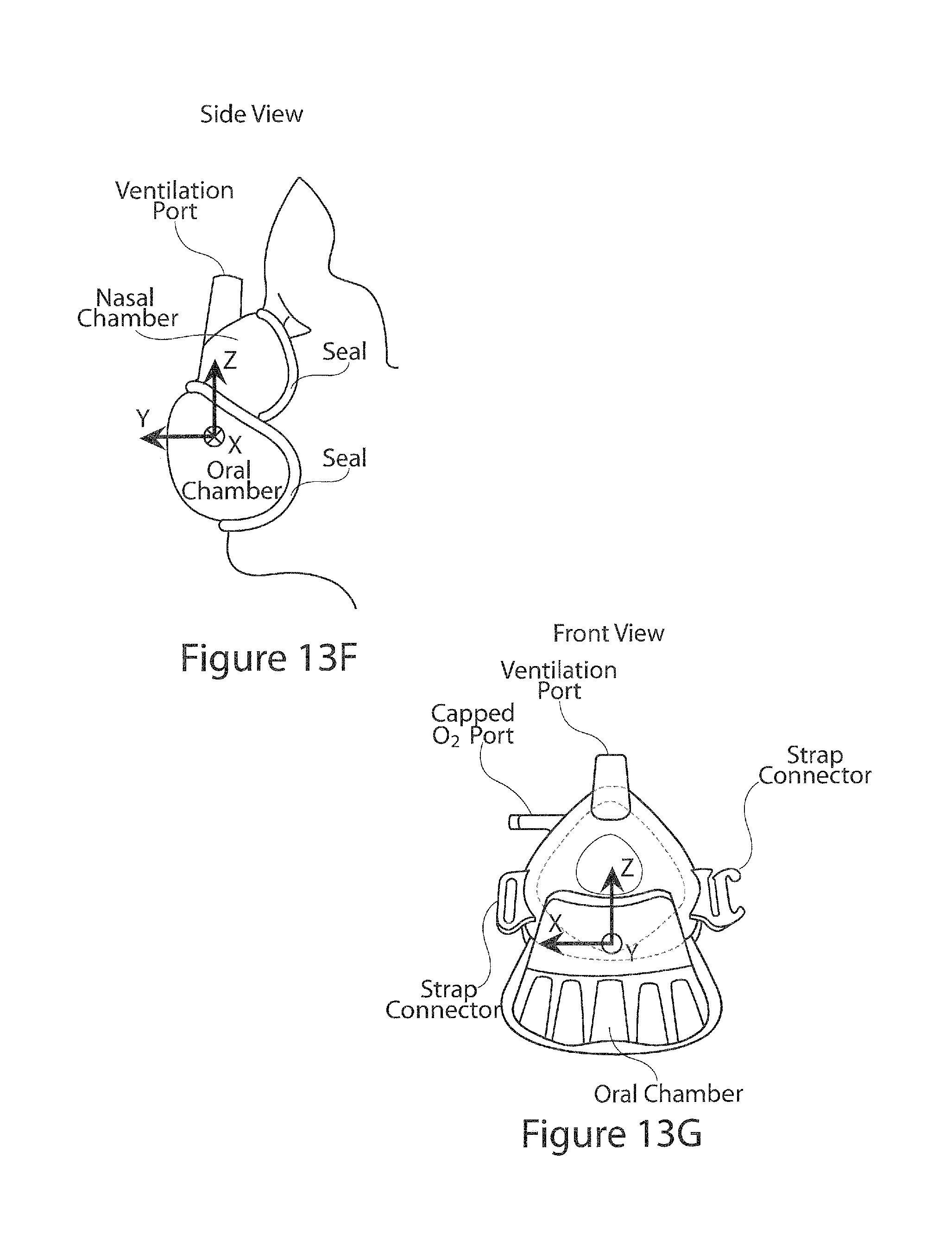
D00013
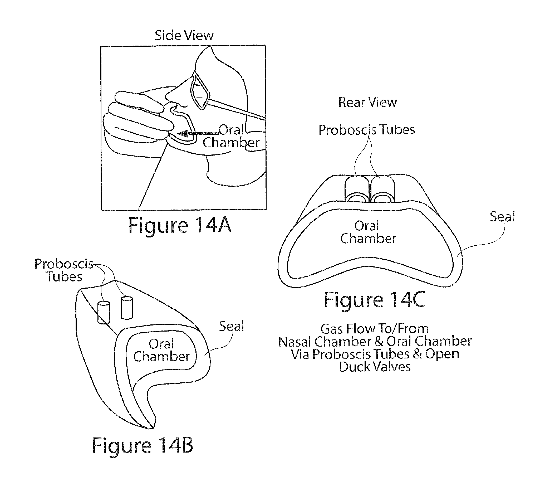
D00014
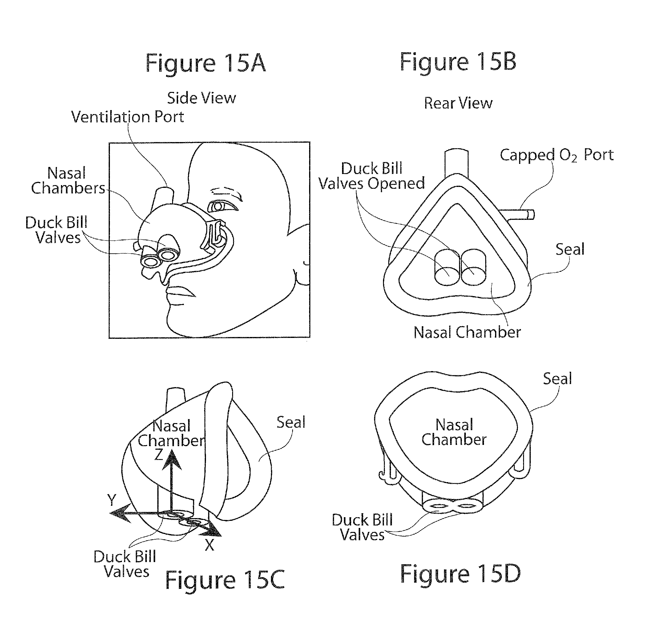
D00015
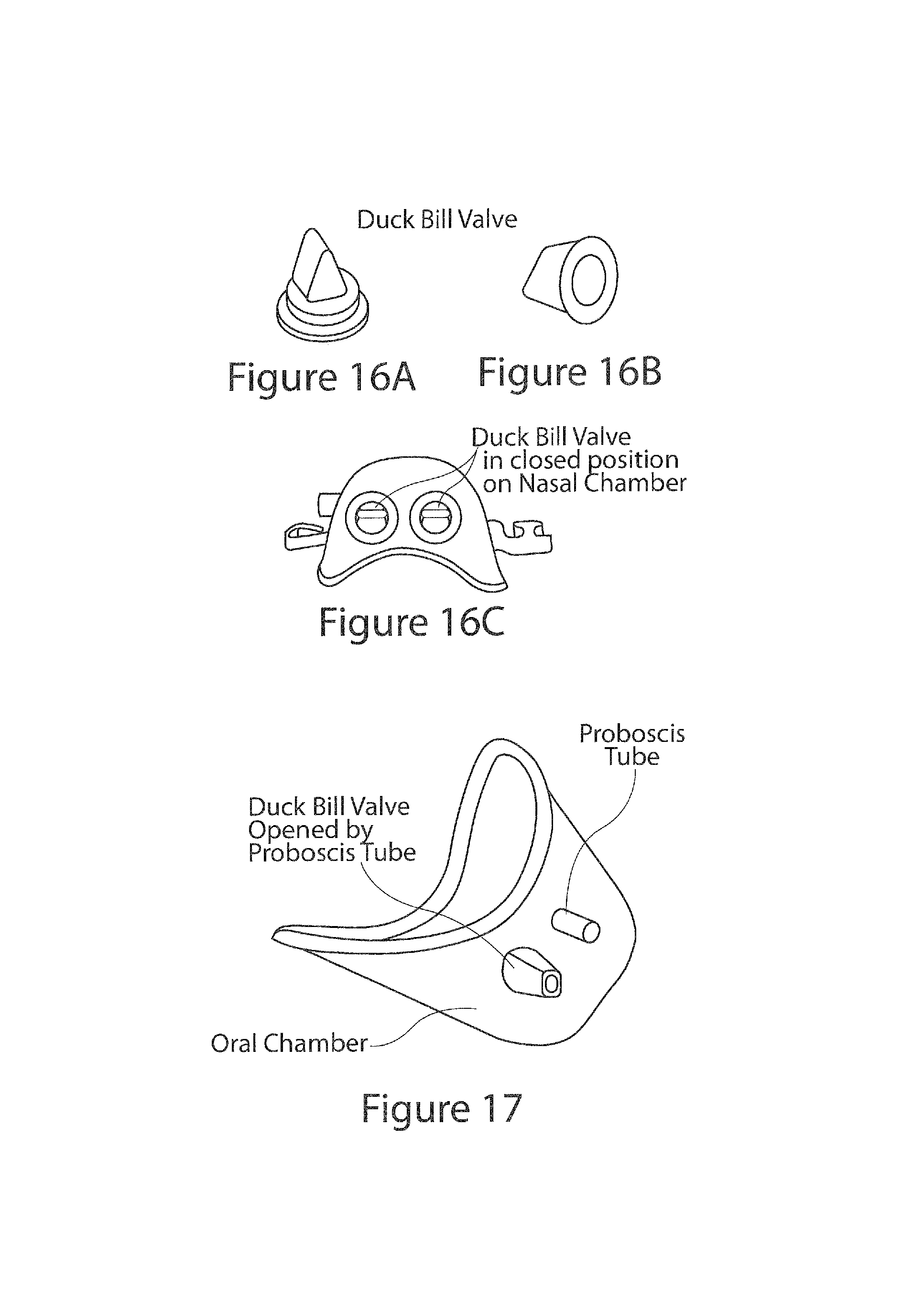
D00016
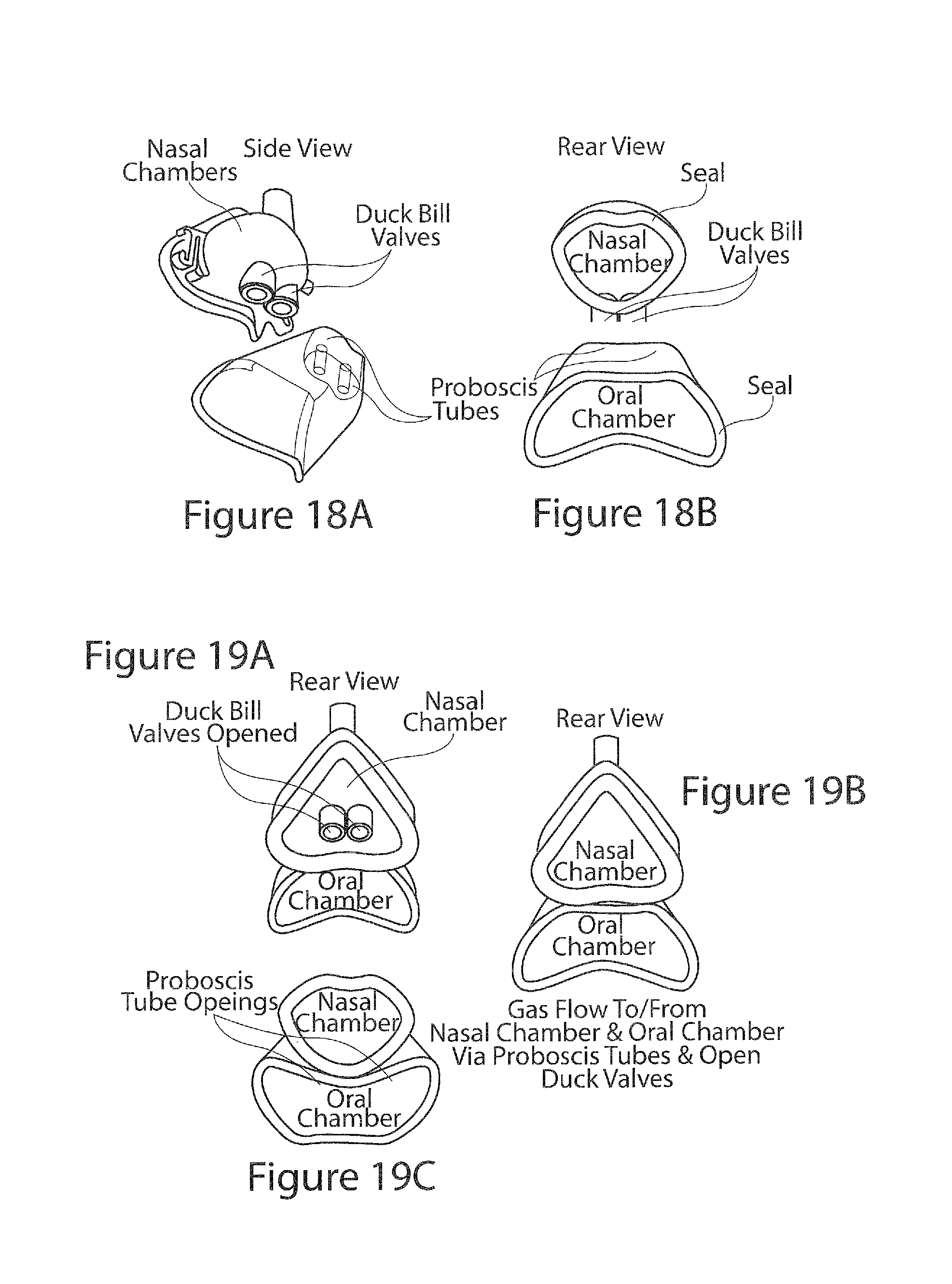
D00017
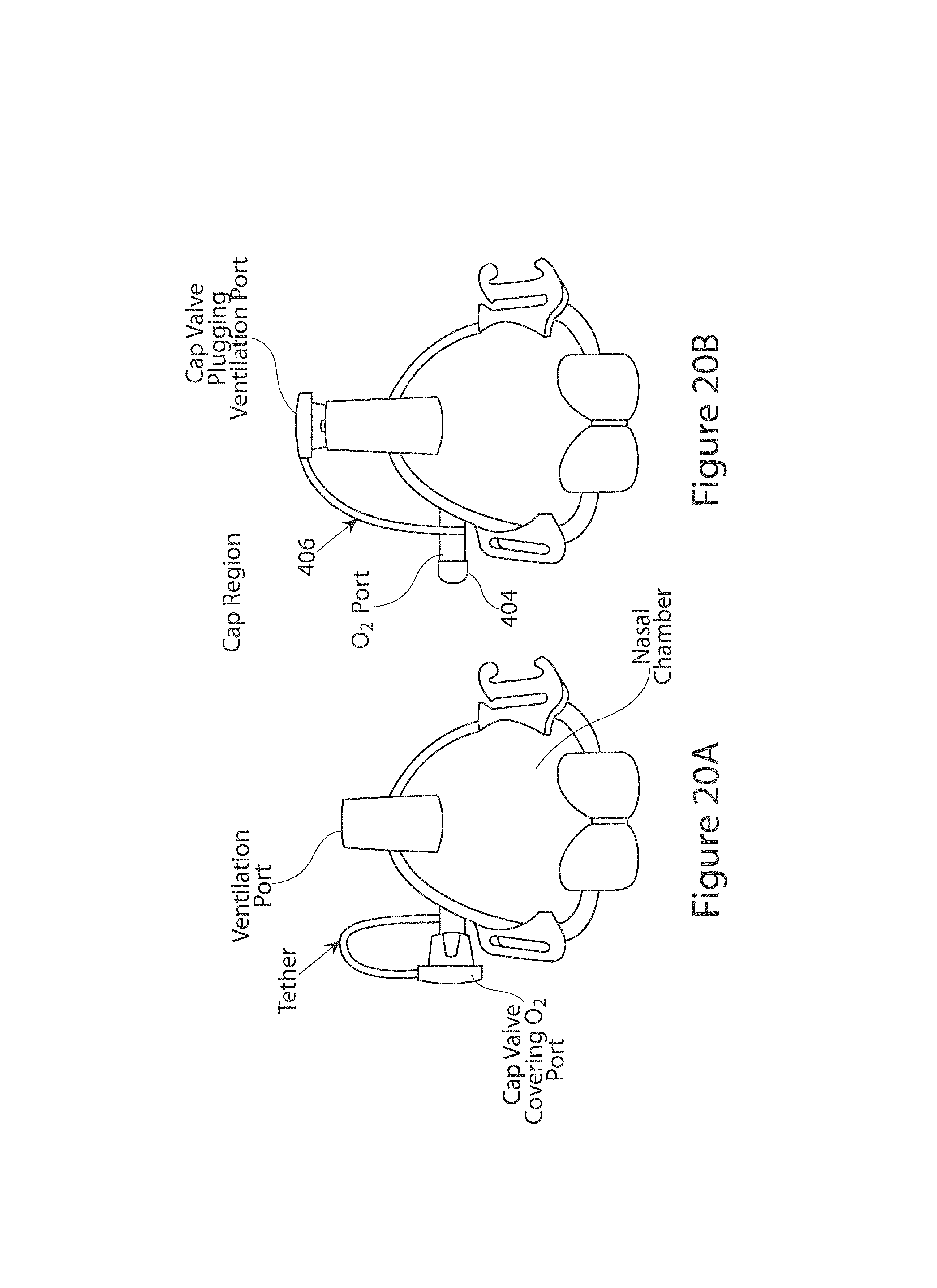
D00018
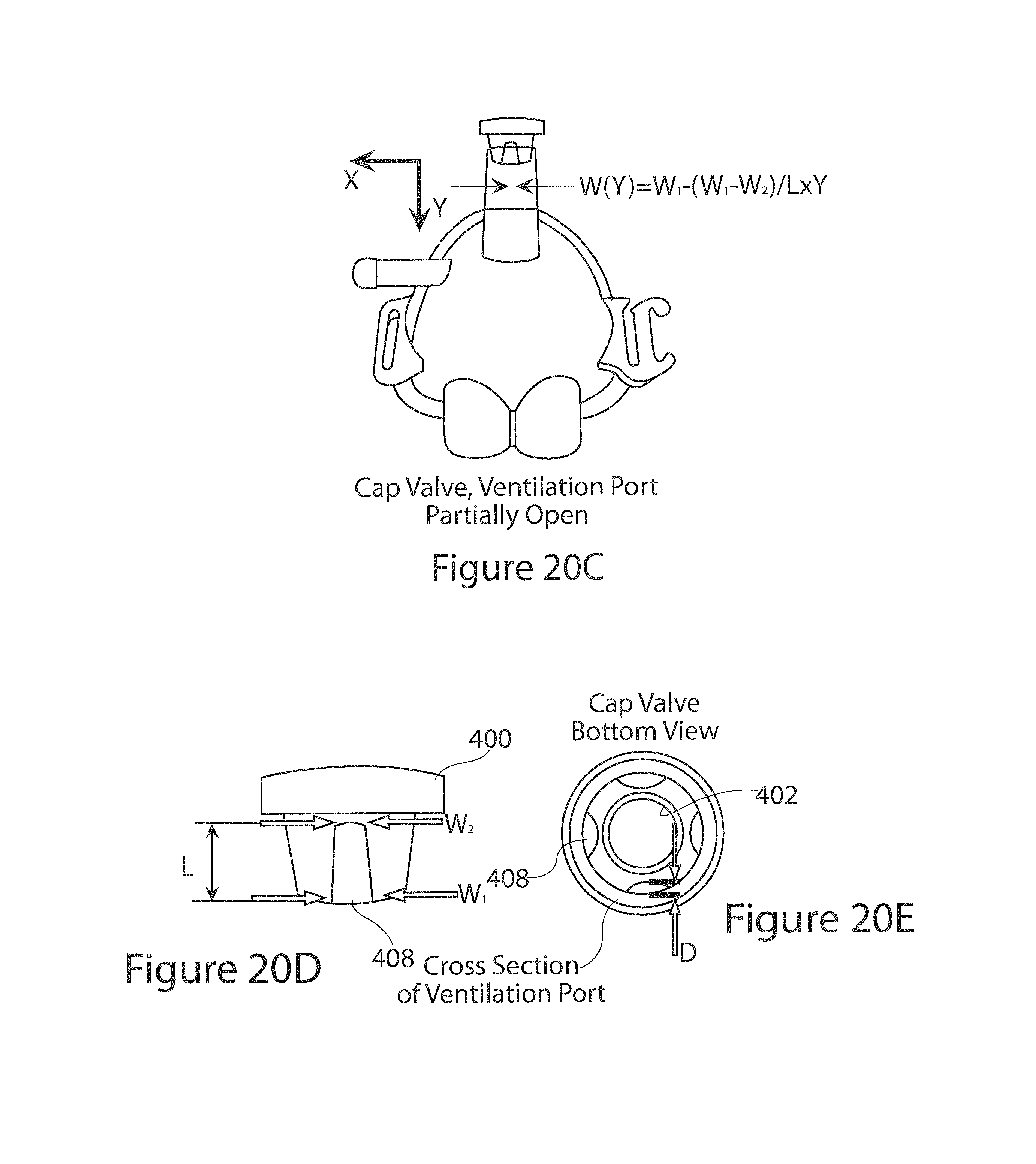
D00019
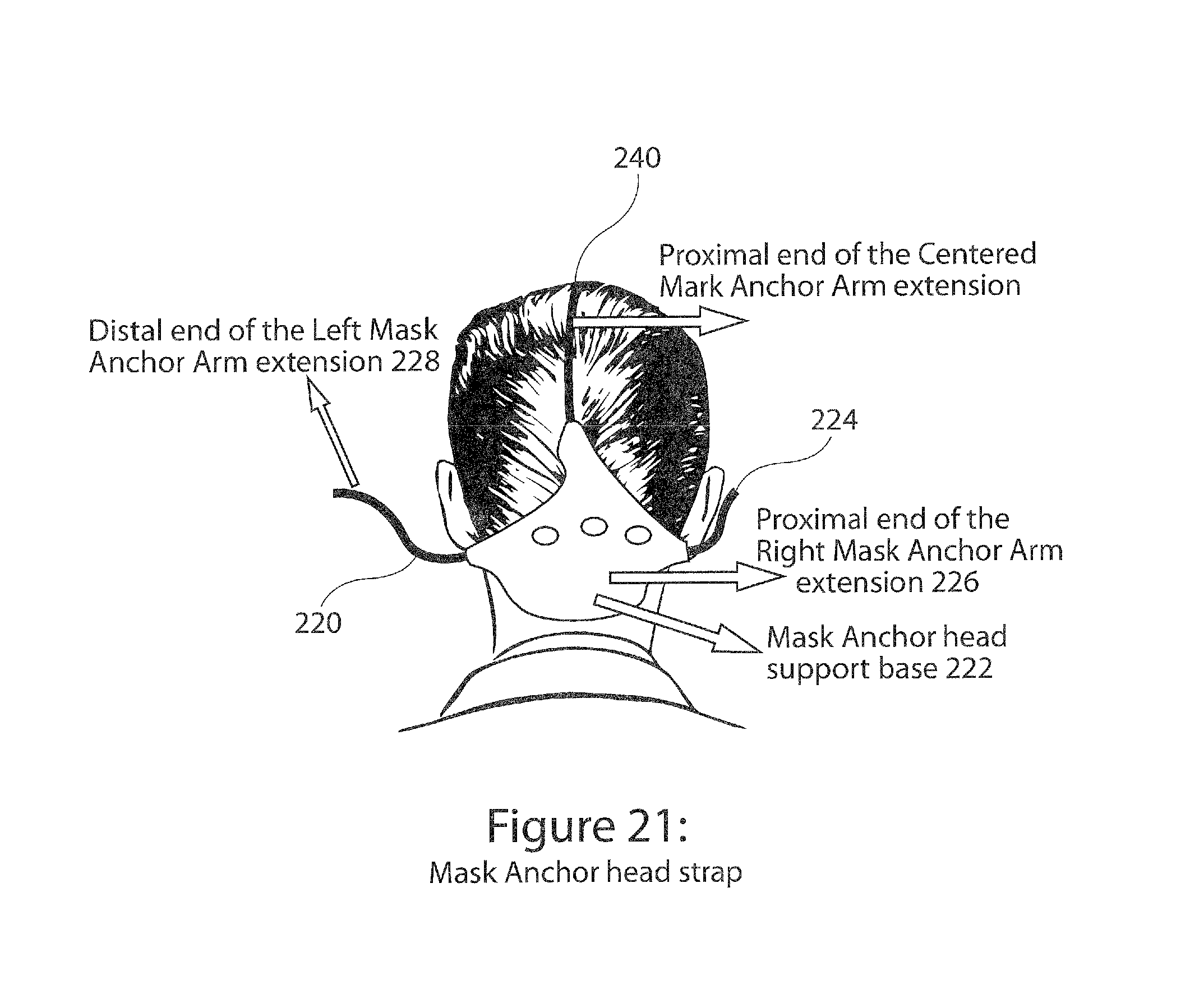
D00020

D00021

D00022
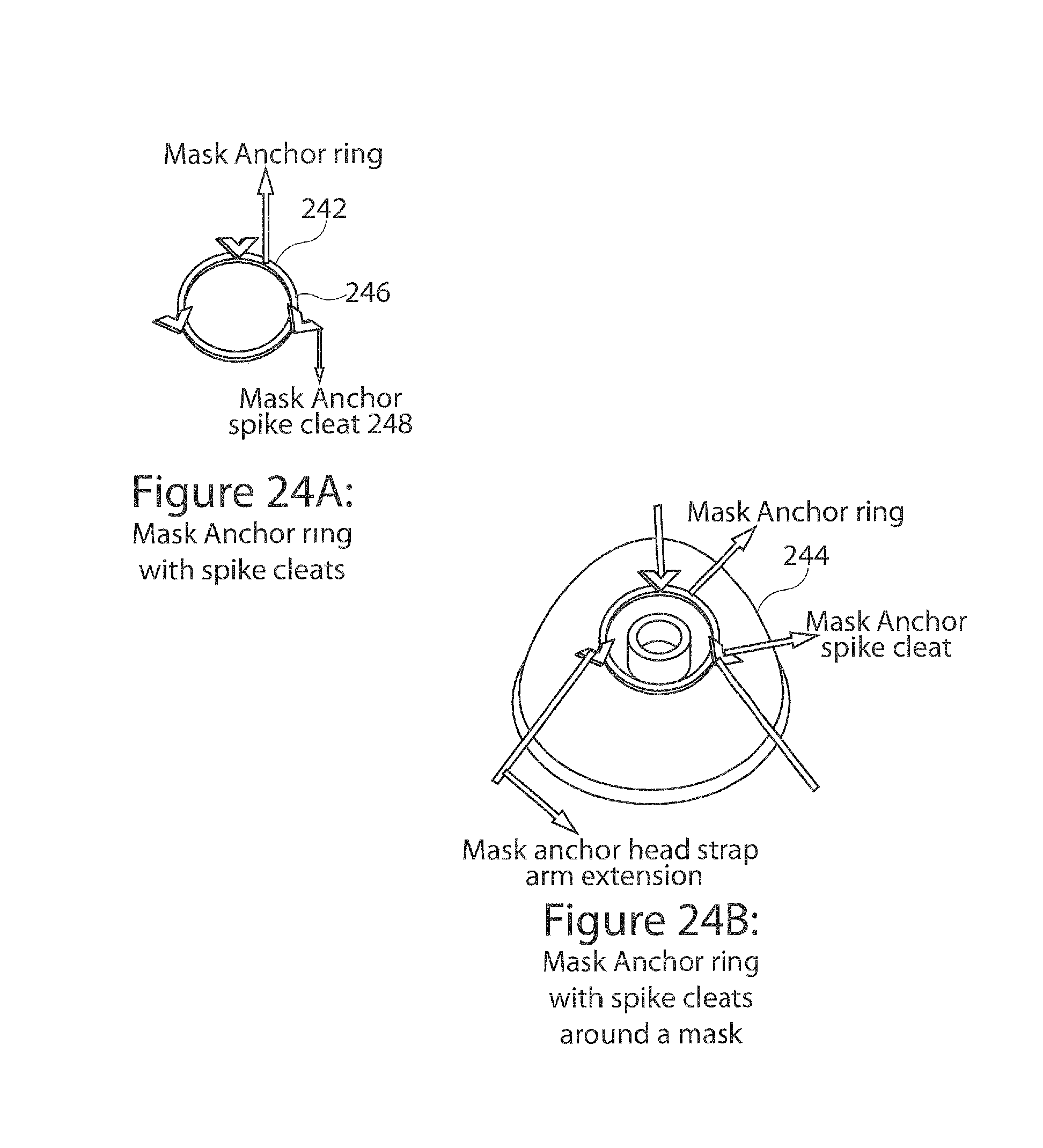
D00023
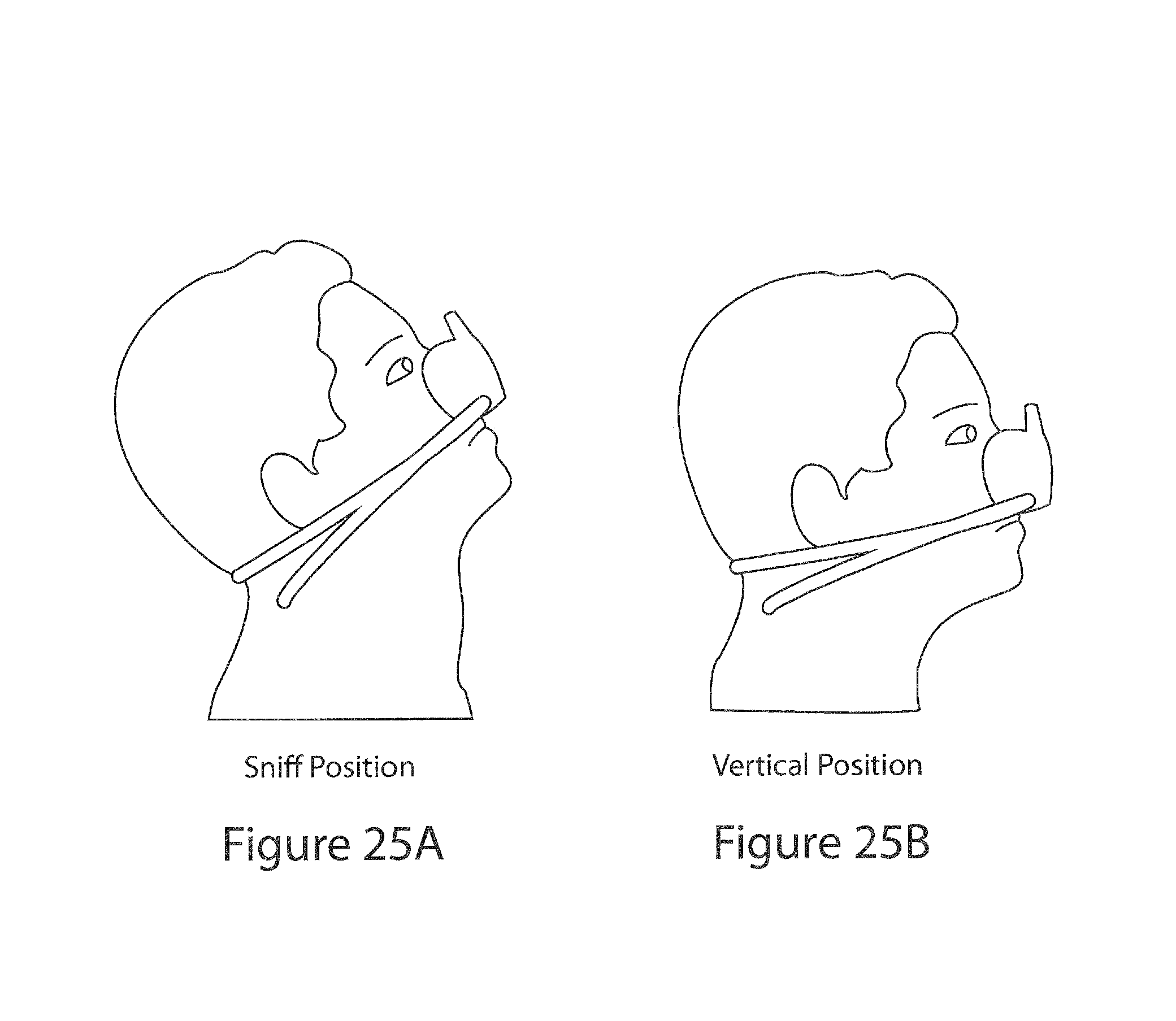
D00024
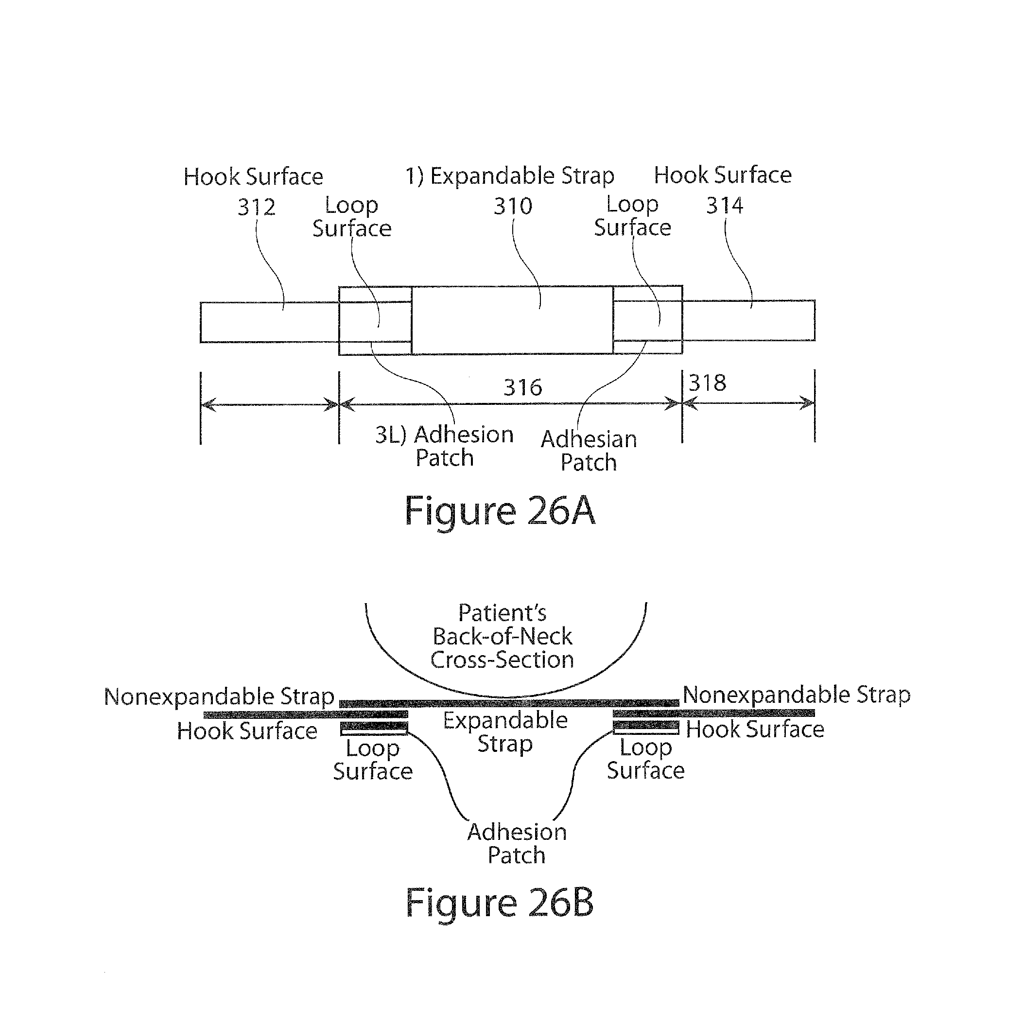
D00025
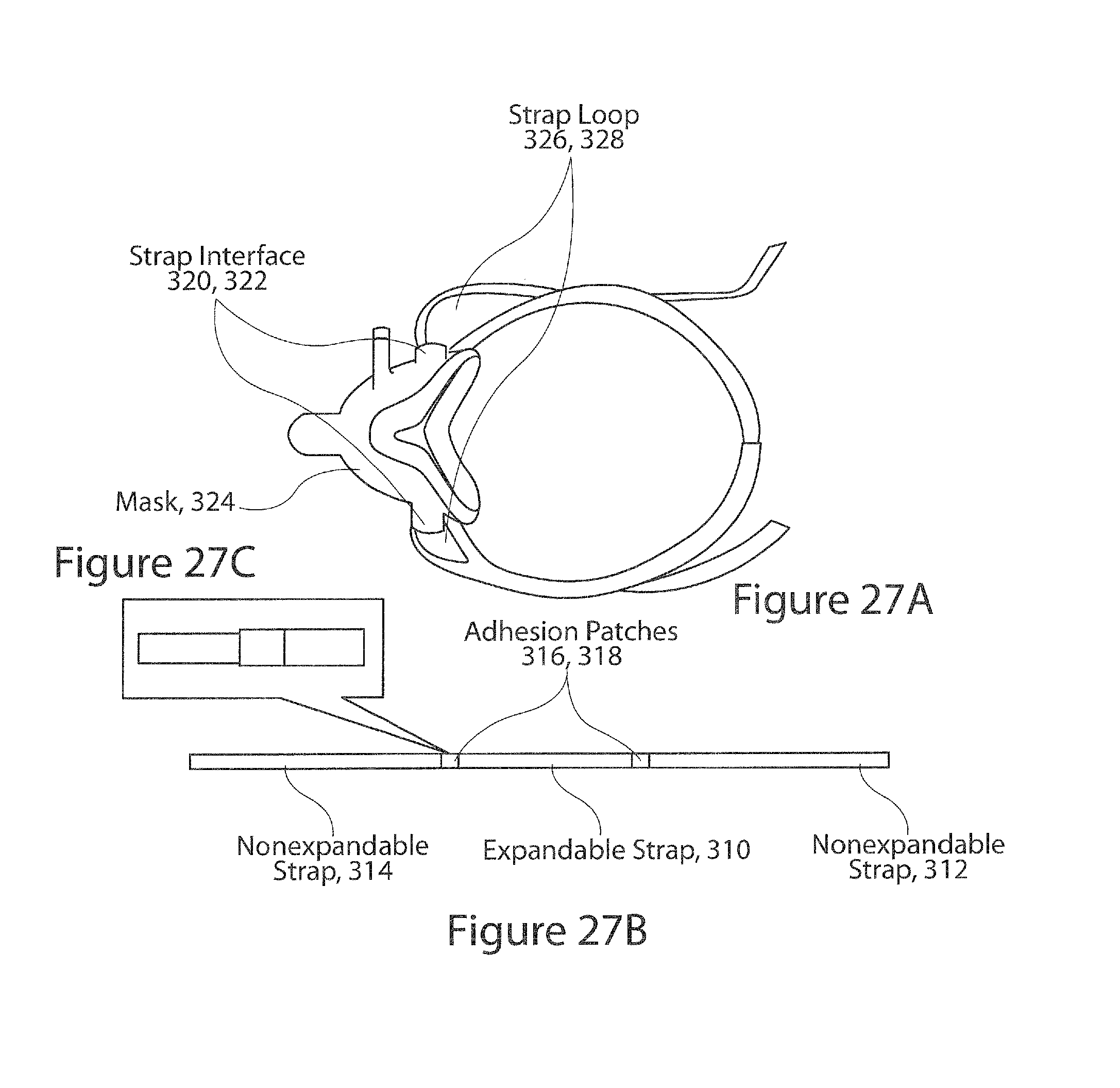
D00026
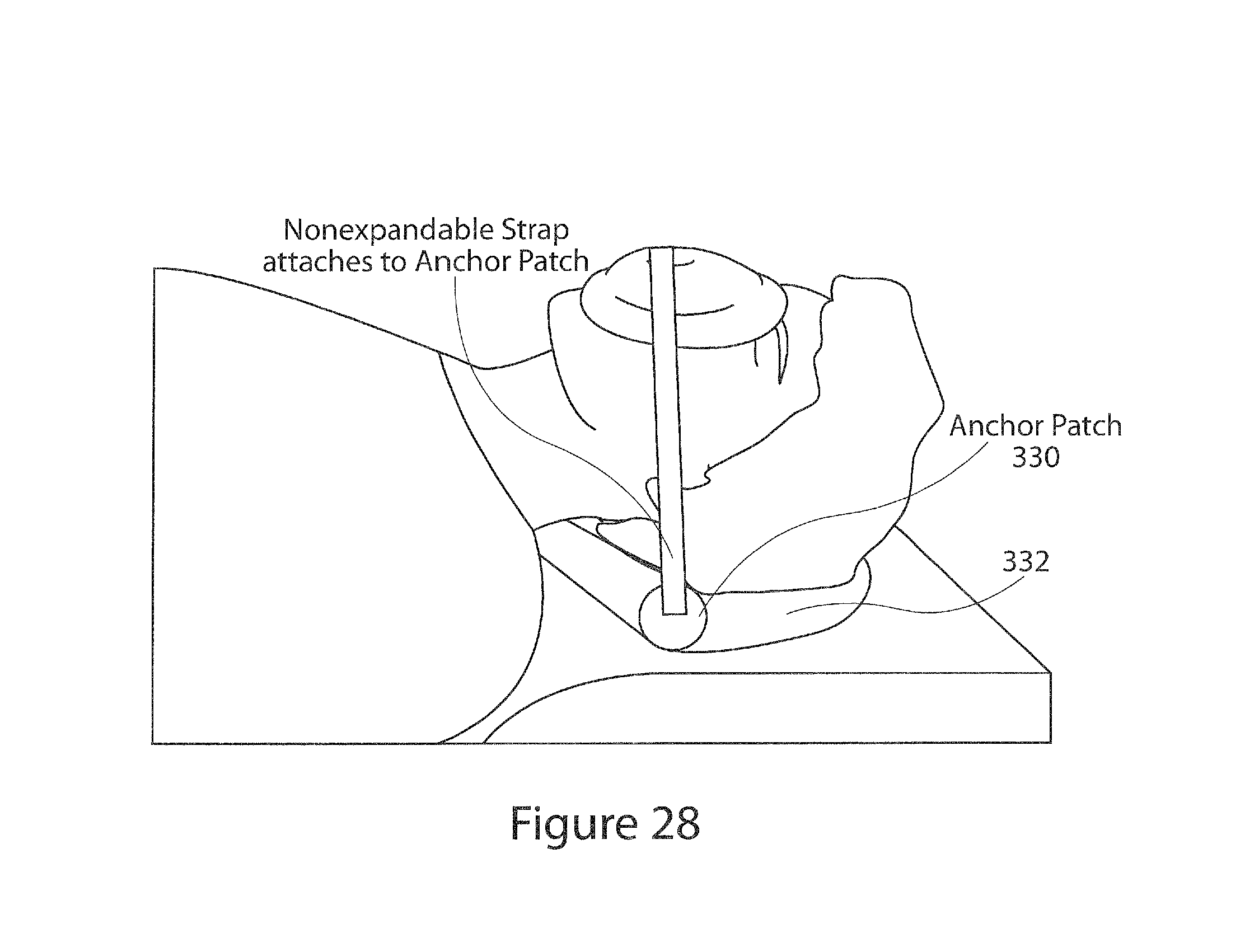
D00027
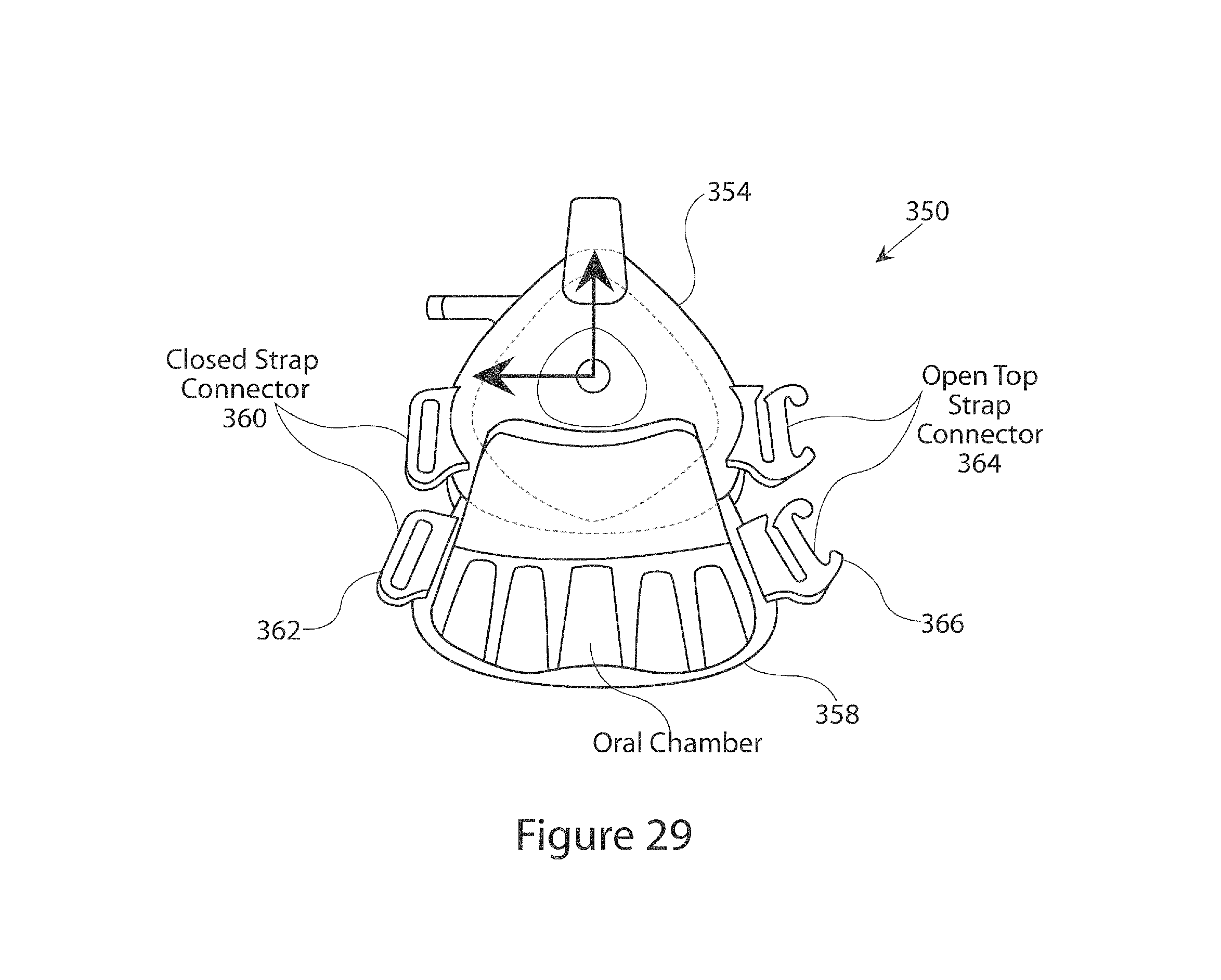
D00028
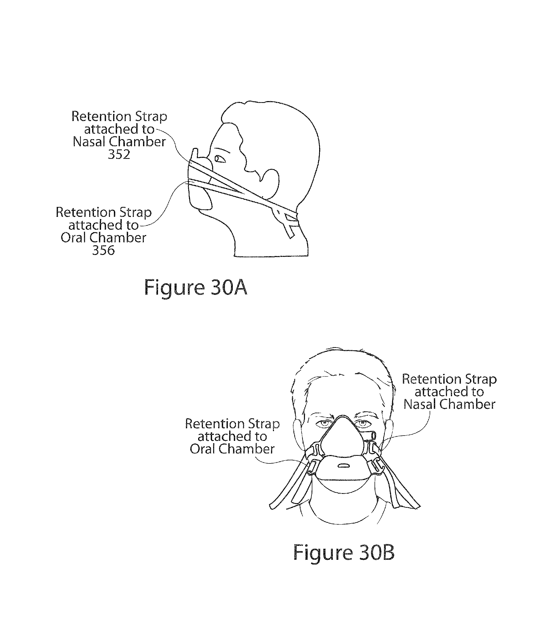
D00029
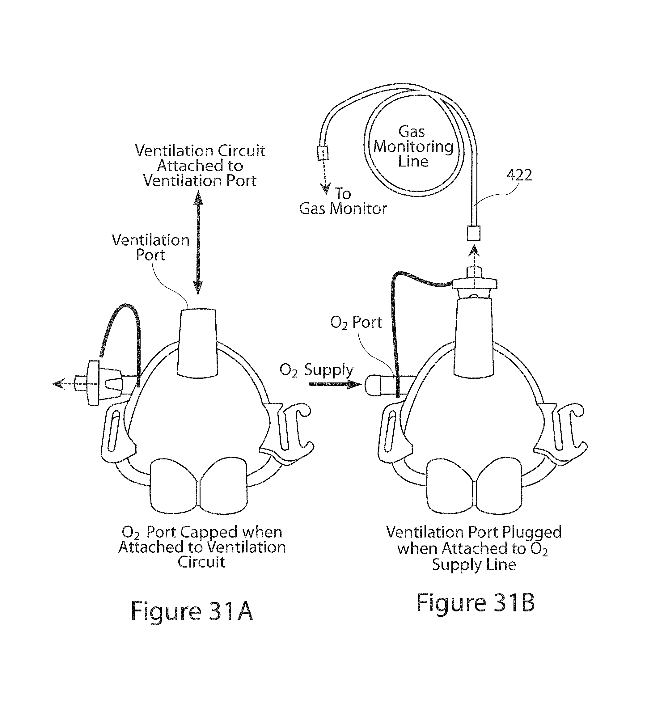
D00030
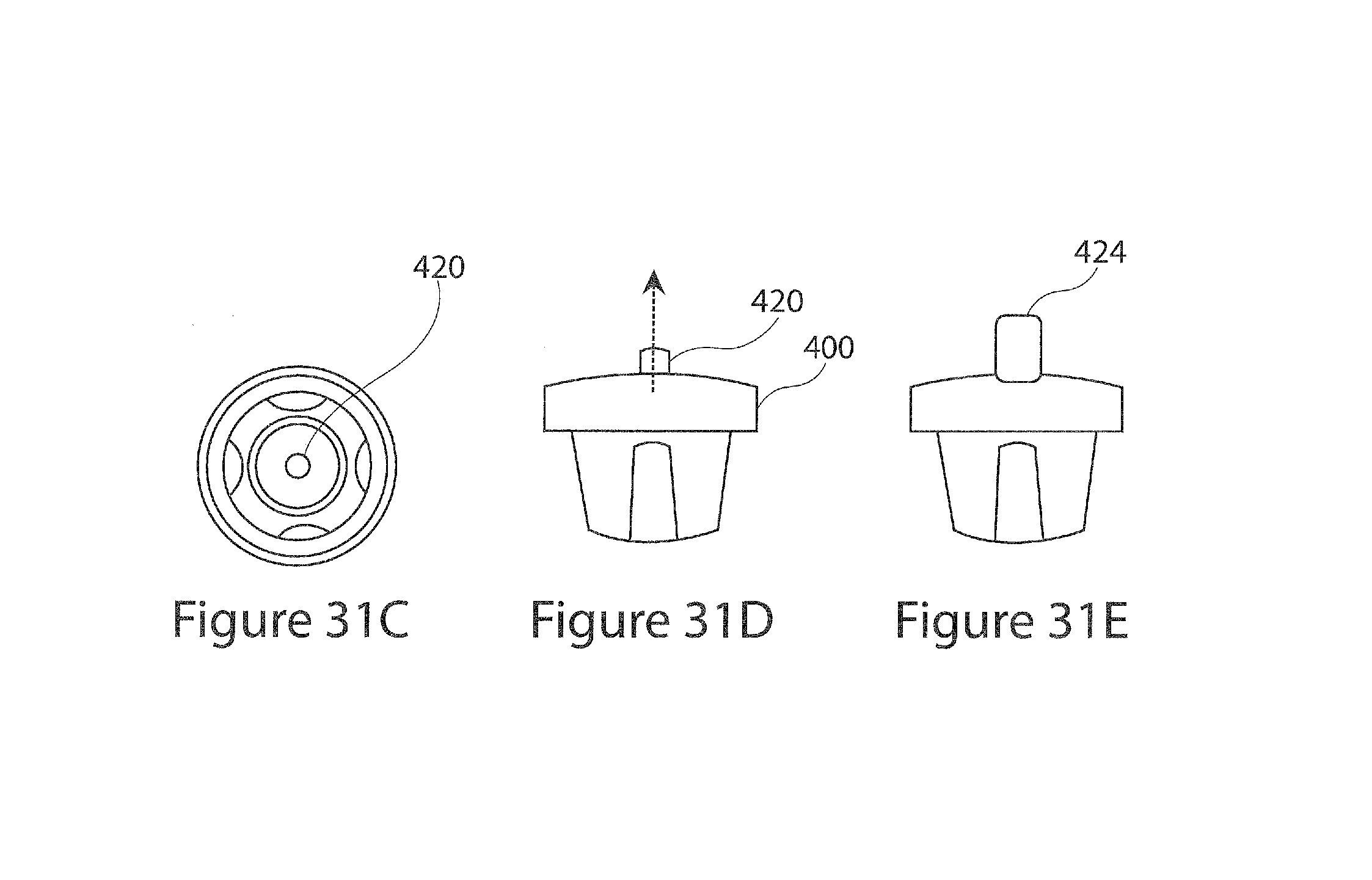
XML
uspto.report is an independent third-party trademark research tool that is not affiliated, endorsed, or sponsored by the United States Patent and Trademark Office (USPTO) or any other governmental organization. The information provided by uspto.report is based on publicly available data at the time of writing and is intended for informational purposes only.
While we strive to provide accurate and up-to-date information, we do not guarantee the accuracy, completeness, reliability, or suitability of the information displayed on this site. The use of this site is at your own risk. Any reliance you place on such information is therefore strictly at your own risk.
All official trademark data, including owner information, should be verified by visiting the official USPTO website at www.uspto.gov. This site is not intended to replace professional legal advice and should not be used as a substitute for consulting with a legal professional who is knowledgeable about trademark law.