Cushion for patient interface
Davidson , et al. December 31, 2
U.S. patent number 8,616,211 [Application Number 13/688,619] was granted by the patent office on 2013-12-31 for cushion for patient interface. This patent grant is currently assigned to ResMed Limited. The grantee listed for this patent is ResMed Limited. Invention is credited to Aaron Samuel Davidson, Matthew Eves, Robin Garth Hitchcock, Susan Robyn Lynch, David John Worboys.


View All Diagrams
| United States Patent | 8,616,211 |
| Davidson , et al. | December 31, 2013 |
Cushion for patient interface
Abstract
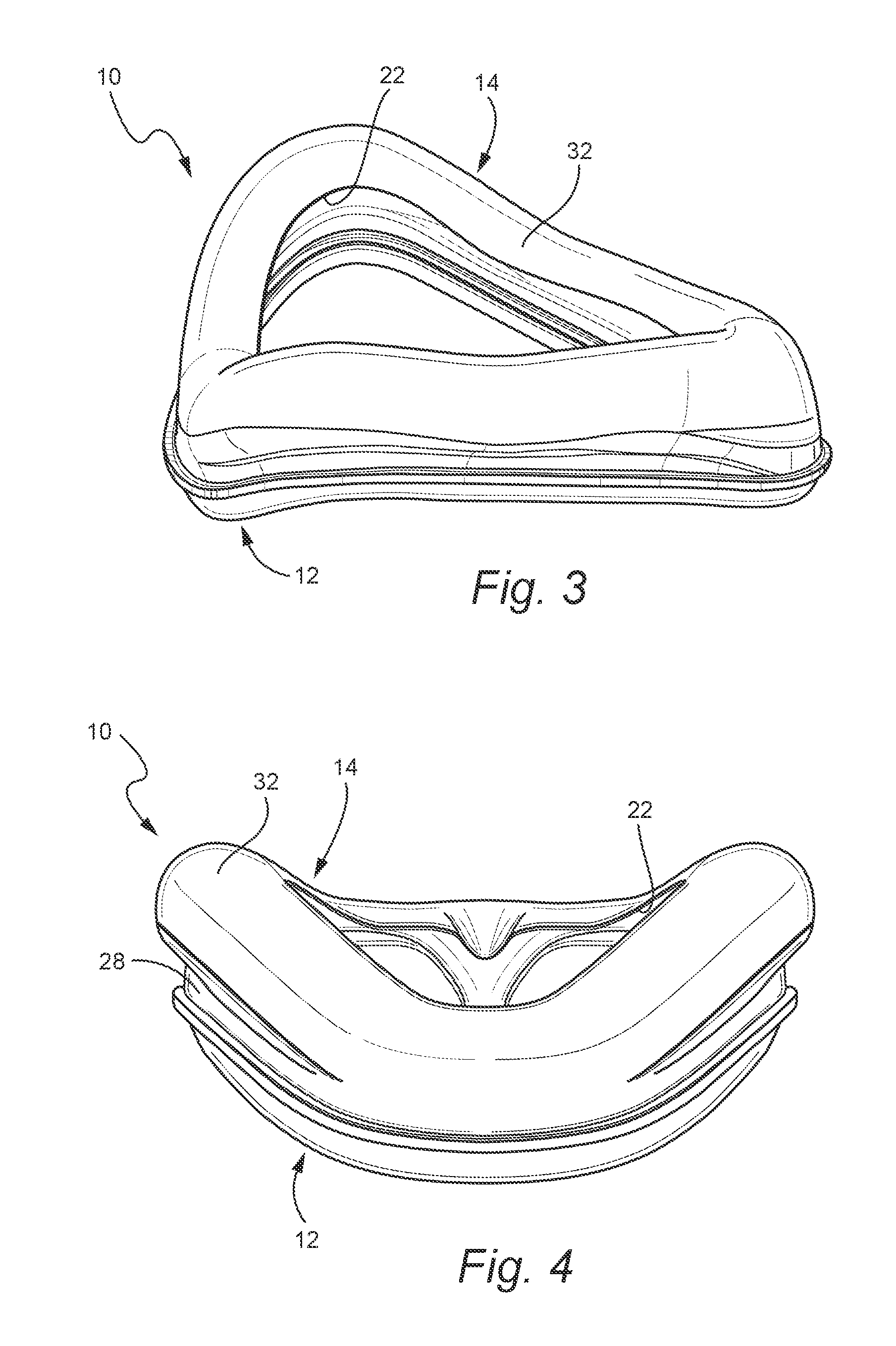
A cushion for a patient interface that delivers breathable gas to a patient includes a base wall structured to be connected to a frame, an underlying support cushion extending away from the base wall towards the patient's face in use, and a membrane provided to substantially cover at least a portion of the underlying cushion. The membrane is adapted to form a continuous seal on the patient's face. The underlying cushion has a spring-like connection with the base wall. The underlying cushion and/or base wall define a spring constant that varies along a length of the seal.
| Inventors: | Davidson; Aaron Samuel (Newport, AU), Hitchcock; Robin Garth (Carlingford, AU), Eves; Matthew (Carlingford, AU), Worboys; David John (Belrose, AU), Lynch; Susan Robyn (Epping, AU) | ||||||||||
|---|---|---|---|---|---|---|---|---|---|---|---|
| Applicant: |
|
||||||||||
| Assignee: | ResMed Limited (Bella Vista,
AU) |
||||||||||
| Family ID: | 36677304 | ||||||||||
| Appl. No.: | 13/688,619 | ||||||||||
| Filed: | November 29, 2012 |
Prior Publication Data
| Document Identifier | Publication Date | |
|---|---|---|
| US 20130092168 A1 | Apr 18, 2013 | |
Related U.S. Patent Documents
| Application Number | Filing Date | Patent Number | Issue Date | ||
|---|---|---|---|---|---|
| 13537876 | Jun 29, 2012 | 8485192 | |||
| 11793981 | 8220459 | ||||
| PCT/AU2006/000032 | Jan 12, 2006 | ||||
| 60724303 | Oct 7, 2005 | ||||
| 60643130 | Jan 12, 2005 | ||||
| Current U.S. Class: | 128/206.24; 128/205.25; 128/206.21; 128/206.12; 128/206.28 |
| Current CPC Class: | A61M 16/06 (20130101); A62B 18/08 (20130101); A61M 16/0616 (20140204); A61M 16/0622 (20140204); Y10T 29/49 (20150115); A61M 16/0611 (20140204) |
| Current International Class: | A62B 18/02 (20060101) |
| Field of Search: | ;128/205.25,206.21-206.26,206.28,207.13 |
References Cited [Referenced By]
U.S. Patent Documents
| 443191 | December 1890 | Illing |
| 781516 | January 1905 | Guthrie, Jr. |
| 812706 | February 1906 | Warbasse |
| 1081745 | December 1913 | Johnston |
| 1125542 | January 1915 | Humphries |
| 1192186 | July 1916 | Greene |
| 1229050 | June 1917 | Donald |
| 1282527 | October 1918 | Bidonde |
| 1362766 | December 1920 | McGargill |
| 1445010 | February 1923 | Feinberg |
| 1610793 | December 1926 | Kaufman |
| 1632449 | June 1927 | McKesson |
| 1653572 | December 1927 | Jackson |
| 1710160 | April 1929 | Gibbs |
| 1926027 | April 1929 | Biggs |
| 1873160 | August 1932 | Sturtevant |
| 2011733 | August 1935 | Shindel |
| 2104016 | January 1938 | Biggs |
| 2123353 | July 1938 | Catt |
| 2130555 | September 1938 | Malcom |
| 2133699 | October 1938 | Heidbrink |
| 2166164 | July 1939 | Lehmberg |
| 2248477 | July 1941 | Lombard |
| 2254854 | September 1941 | O'Connell |
| 2317608 | April 1943 | Heidbrink |
| 2353643 | July 1944 | Bulbulian |
| 2371965 | March 1945 | Lehmberg |
| 2376871 | May 1945 | Fink |
| 2415846 | February 1947 | Randall |
| 2428451 | October 1947 | Emerson |
| 2433565 | December 1947 | Korman |
| 2438058 | March 1948 | Kincheloe |
| 2578621 | December 1951 | Yant |
| 2625155 | January 1953 | Engelder |
| 2641253 | June 1953 | Engelder |
| 2875759 | December 1954 | Galleher |
| 2706983 | April 1955 | Matheson et al. |
| 2749910 | June 1956 | Faulconer, Jr. |
| RE24193 | August 1956 | Emerson |
| 2837090 | June 1958 | Bloom et al. |
| 2875757 | March 1959 | Galleher, Jr. |
| 2881444 | April 1959 | Fresh et al. |
| 2882895 | April 1959 | Galeazzi |
| 2902033 | September 1959 | Galleher, Jr. |
| 2931356 | April 1960 | Schwarz |
| D188084 | May 1960 | Garelick |
| 2939458 | June 1960 | Lundquist |
| 3013556 | December 1961 | Galleher, Jr. |
| 3182659 | May 1965 | Blount |
| 3189027 | June 1965 | Bartlett, Jr. |
| 3238943 | March 1966 | Holley |
| 3315674 | April 1967 | Bloom et al. |
| 3330273 | July 1967 | Bennett |
| 3330274 | July 1967 | Bennett |
| 3362420 | January 1968 | Blackburn et al. |
| 3363833 | January 1968 | Laerdal |
| 3545436 | December 1970 | Holloway |
| 3556122 | January 1971 | Laerdal |
| 3580051 | May 1971 | Blevins |
| 3670726 | June 1972 | Mahon et al. |
| 3682171 | August 1972 | Dali et al. |
| 3700000 | October 1972 | Hesse |
| 3720235 | March 1973 | Schrock |
| 3739774 | June 1973 | Gregory |
| 3754552 | August 1973 | King |
| 3796216 | March 1974 | Schwarz |
| 3799164 | March 1974 | Rollins |
| D231803 | June 1974 | Huddy |
| 3861385 | January 1975 | Carden |
| 3902486 | September 1975 | Guichard |
| 3905361 | September 1975 | Hewson et al. |
| 3910261 | October 1975 | Ragsdale et al. |
| 3938614 | February 1976 | Ahs |
| 3972321 | August 1976 | Proctor |
| 4006744 | February 1977 | Steer |
| 4062357 | December 1977 | Laerdal |
| 4069516 | January 1978 | Watkins, Jr. |
| 4077404 | March 1978 | Elam |
| D250131 | October 1978 | Lewis et al. |
| 4142527 | March 1979 | Garcia |
| 4153051 | May 1979 | Shippert |
| 4156426 | May 1979 | Gold |
| 4167185 | September 1979 | Lewis |
| 4226234 | October 1980 | Gunderson |
| 4239038 | December 1980 | Holmes |
| 4245632 | January 1981 | Houston |
| 4248218 | February 1981 | Fischer |
| 4263908 | April 1981 | Mizerak |
| 4264743 | April 1981 | Maruyama et al. |
| 4265239 | May 1981 | Fischer, Jr. et al. |
| 4267845 | May 1981 | Robertson, Jr. et al. |
| 4273124 | June 1981 | Zimmerman |
| D262322 | December 1981 | Mizerak |
| 4304229 | December 1981 | Curtin |
| 4312359 | January 1982 | Olson |
| 4328797 | May 1982 | Rollins et al. |
| 4347205 | August 1982 | Stewart |
| 4354488 | October 1982 | Bartos |
| 4367735 | January 1983 | Dali |
| 4367816 | January 1983 | Wilkes |
| 4402316 | September 1983 | Gadberry |
| 4406283 | September 1983 | Bir |
| 4412537 | November 1983 | Tiger |
| 4414973 | November 1983 | Matheson et al. |
| 4422456 | December 1983 | Teip |
| 4449526 | May 1984 | Elam |
| 4455675 | June 1984 | Bose et al. |
| 4467799 | August 1984 | Steinberg |
| 4493614 | January 1985 | Chu et al. |
| 4522639 | June 1985 | Ansite et al. |
| 4548200 | October 1985 | Wapner |
| 4549542 | October 1985 | Chein |
| 4558710 | December 1985 | Eichler |
| 4572323 | February 1986 | Randall |
| 4587967 | May 1986 | Chu et al. |
| 4601465 | July 1986 | Roy |
| D285496 | September 1986 | Berman |
| 4616647 | October 1986 | McCreadie |
| 4617637 | October 1986 | Chu et al. |
| 4622964 | November 1986 | Flynn |
| 4630604 | December 1986 | Montesi |
| 4641645 | February 1987 | Tayebi |
| 4641647 | February 1987 | Behan |
| D289238 | April 1987 | Arthur, Jr. |
| 4655213 | April 1987 | Rapoport et al. |
| 4660555 | April 1987 | Payton |
| 4665570 | May 1987 | Davis |
| 4671267 | June 1987 | Stout |
| 4671271 | June 1987 | Bishop et al. |
| 4676241 | June 1987 | Webb et al. |
| 4677975 | July 1987 | Edgar et al. |
| 4677977 | July 1987 | Wilcox |
| 4699139 | October 1987 | Marshall et al. |
| 4706664 | November 1987 | Snook et al. |
| 4711636 | December 1987 | Bierman |
| 4713844 | December 1987 | Westgate |
| H397 | January 1988 | Stark |
| D293613 | January 1988 | Wingler |
| 4739755 | April 1988 | White et al. |
| 4753233 | June 1988 | Grimes |
| 4767411 | August 1988 | Edmunds |
| 4770169 | September 1988 | Schmoegner et al. |
| 4774941 | October 1988 | Cook |
| 4774946 | October 1988 | Ackerman et al. |
| 4782832 | November 1988 | Trimble et al. |
| 4790829 | December 1988 | Bowden et al. |
| 4799477 | January 1989 | Lewis |
| 4802857 | February 1989 | Laughlin |
| 4803981 | February 1989 | Vickery |
| 4809692 | March 1989 | Nowacki et al. |
| 4811730 | March 1989 | Milano |
| 4819629 | April 1989 | Jonson |
| 4821713 | April 1989 | Bauman |
| 4830138 | May 1989 | Palmaer et al. |
| 4838878 | June 1989 | Kalt et al. |
| 4841953 | June 1989 | Dodrill |
| 4848334 | July 1989 | Bellm |
| 4848366 | July 1989 | Aita et al. |
| 4899740 | February 1990 | Napolitano |
| 4905683 | March 1990 | Cronjaeger |
| 4907584 | March 1990 | McGinnis |
| 4910806 | March 1990 | Baker et al. |
| 4914957 | April 1990 | Dougherty |
| 4915105 | April 1990 | Lee |
| 4919128 | April 1990 | Kopala et al. |
| 4919654 | April 1990 | Kalt |
| 4938210 | July 1990 | Shene |
| 4938212 | July 1990 | Snook et al. |
| 4941476 | July 1990 | Fisher |
| 4944310 | July 1990 | Sullivan |
| 4945907 | August 1990 | Tayebi |
| 4947860 | August 1990 | Fisher |
| D310431 | September 1990 | Bellm |
| 4960121 | October 1990 | Nelson et al. |
| 4966590 | October 1990 | Kalt |
| 4969880 | November 1990 | Zamierowski |
| 4971051 | November 1990 | Toffolon |
| 4976698 | December 1990 | Stokley |
| 4986269 | January 1991 | Hakkinen |
| 4989596 | February 1991 | Macris et al. |
| 4989599 | February 1991 | Carter |
| 4996983 | March 1991 | Amrhein |
| 5000173 | March 1991 | Zalkin et al. |
| 5003633 | April 1991 | Itoh |
| 5005568 | April 1991 | Loescher et al. |
| 5005571 | April 1991 | Dietz |
| 5020163 | June 1991 | Aileo et al. |
| 5022900 | June 1991 | Bar-Yona et al. |
| 5023955 | June 1991 | Murphy, II et al. |
| 5025805 | June 1991 | Nutter |
| 5038772 | August 1991 | Kolbe et al. |
| 5038776 | August 1991 | Harrison et al. |
| 5042473 | August 1991 | Lewis |
| 5042478 | August 1991 | Kopala et al. |
| 5046200 | September 1991 | Feder |
| 5046491 | September 1991 | Derrick |
| 5062421 | November 1991 | Burns et al. |
| 5063922 | November 1991 | Hakkinen |
| 5069205 | December 1991 | Urso |
| 5074297 | December 1991 | Venegas |
| 5080092 | January 1992 | Tenna |
| D323908 | February 1992 | Holister et al. |
| 5109839 | May 1992 | Blasdell et al. |
| 5109840 | May 1992 | Daleiden |
| 5113857 | May 1992 | Dickerman et al. |
| 5117818 | June 1992 | Palfy |
| 5121745 | June 1992 | Israel |
| 5121746 | June 1992 | Sikora |
| 5127397 | July 1992 | Kohnke |
| 5133347 | July 1992 | Huennebeck |
| 5137017 | August 1992 | Salter |
| 5138722 | August 1992 | Urella et al. |
| 5140980 | August 1992 | Haughey et al. |
| 5140982 | August 1992 | Bauman |
| 5159938 | November 1992 | Laughlin |
| 5178138 | January 1993 | Walstrom et al. |
| 5181506 | January 1993 | Tardiff, Jr. et al. |
| D333015 | February 1993 | Farmer et al. |
| 5188101 | February 1993 | Tumolo |
| D334633 | April 1993 | Rudolph |
| 5207665 | May 1993 | Davis et al. |
| 5220699 | June 1993 | Farris |
| 5222478 | June 1993 | Scarberry et al. |
| 5231983 | August 1993 | Matson et al. |
| 5233978 | August 1993 | Callaway |
| 5243709 | September 1993 | Sheehan et al. |
| 5243971 | September 1993 | Sullivan et al. |
| 5245995 | September 1993 | Sullivan et al. |
| 5261893 | November 1993 | Zamierowski |
| 5263939 | November 1993 | Wortrich |
| 5265592 | November 1993 | Beaussant |
| 5265595 | November 1993 | Rudolph |
| 5267557 | December 1993 | Her-Mou |
| 5269296 | December 1993 | Landis |
| 5271391 | December 1993 | Graves |
| 5279289 | January 1994 | Kirk |
| 5280784 | January 1994 | Kohler |
| 5299448 | April 1994 | Maryyanek |
| 5299579 | April 1994 | Gedeon et al. |
| 5299599 | April 1994 | Farmer et al. |
| 5304146 | April 1994 | Johnson et al. |
| 5311862 | May 1994 | Blasdell et al. |
| 5322057 | June 1994 | Raabe et al. |
| D349586 | August 1994 | Handke |
| 5335656 | August 1994 | Bowe et al. |
| 5343878 | September 1994 | Scarberry et al. |
| 5349949 | September 1994 | Schegerin |
| 5353789 | October 1994 | Schlobohm |
| 5355878 | October 1994 | Griffiths et al. |
| 5355893 | October 1994 | Mick et al. |
| 5357951 | October 1994 | Ratner |
| 5364367 | November 1994 | Banks et al. |
| 5372130 | December 1994 | Stern et al. |
| 5372388 | December 1994 | Gargiulo |
| 5372389 | December 1994 | Tam et al. |
| 5372390 | December 1994 | Conway et al. |
| 5372391 | December 1994 | Bast et al. |
| 5375593 | December 1994 | Press |
| 5385141 | January 1995 | Granatiero |
| 5388571 | February 1995 | Roberts et al. |
| 5391248 | February 1995 | Brain |
| 5394568 | March 1995 | Brostrom et al. |
| 5396885 | March 1995 | Nelson |
| 5398676 | March 1995 | Press et al. |
| 5400776 | March 1995 | Bartholomew |
| 5404871 | April 1995 | Goodman et al. |
| 5419318 | May 1995 | Tayebi |
| 5425359 | June 1995 | Liou |
| 5429126 | July 1995 | Bracken |
| 5429683 | July 1995 | Le Mitouard |
| 5431158 | July 1995 | Tirotta |
| 5437267 | August 1995 | Weinstein et al. |
| 5438981 | August 1995 | Starr et al. |
| 5441046 | August 1995 | Starr et al. |
| D362061 | September 1995 | McGinnis et al. |
| 5462528 | October 1995 | Roewer |
| 5477852 | December 1995 | Landis et al. |
| 5479920 | January 1996 | Piper et al. |
| 5488948 | February 1996 | Dubruille et al. |
| 5492116 | February 1996 | Scarberry et al. |
| 5501214 | March 1996 | Sabo |
| 5503147 | April 1996 | Bertheau |
| 5509404 | April 1996 | Lloyd et al. |
| 5509409 | April 1996 | Weatherholt |
| 5513634 | May 1996 | Jackson |
| 5513635 | May 1996 | Bedi |
| 5517986 | May 1996 | Starr et al. |
| 5526806 | June 1996 | Sansoni |
| 5533506 | July 1996 | Wood |
| 5538000 | July 1996 | Rudolph |
| 5538001 | July 1996 | Bridges |
| 5540223 | July 1996 | Starr et al. |
| 5542128 | August 1996 | Lomas |
| 5546936 | August 1996 | Virag et al. |
| 5558090 | September 1996 | James |
| RE35339 | October 1996 | Rapoport |
| 5560354 | October 1996 | Berthon-Jones et al. |
| 5570682 | November 1996 | Johnson |
| 5570684 | November 1996 | Behr |
| 5570689 | November 1996 | Starr et al. |
| D377089 | December 1996 | Starr et al. |
| 5592938 | January 1997 | Scarberry et al. |
| 5608647 | March 1997 | Rubsamen et al. |
| 5623923 | April 1997 | Bertheau et al. |
| 5642726 | July 1997 | Owens et al. |
| 5642730 | July 1997 | Baran |
| 5647355 | July 1997 | Starr et al. |
| 5647356 | July 1997 | Osendorf et al. |
| 5647357 | July 1997 | Barnett et al. |
| 5649532 | July 1997 | Griffiths |
| 5649533 | July 1997 | Oren |
| 5653228 | August 1997 | Byrd |
| 5655520 | August 1997 | Howe et al. |
| 5655527 | August 1997 | Scarberry et al. |
| 5657493 | August 1997 | Ferrero et al. |
| 5657752 | August 1997 | Landis et al. |
| 5660171 | August 1997 | Kimm et al. |
| 5662101 | September 1997 | Ogden et al. |
| 5666946 | September 1997 | Langenback |
| 5676133 | October 1997 | Hickle et al. |
| 5682881 | November 1997 | Winthrop et al. |
| 5685296 | November 1997 | Zdrojkowski |
| 5687715 | November 1997 | Landis et al. |
| D389238 | January 1998 | Kirk, III et al. |
| 5704345 | January 1998 | Berthon-Jones et al. |
| 5707342 | January 1998 | Tanaka |
| 5715814 | February 1998 | Ebers |
| 5724965 | March 1998 | Handke et al. |
| 5735272 | April 1998 | Dillon et al. |
| 5740799 | April 1998 | Nielsen |
| 5746201 | May 1998 | Kidd |
| 5752509 | May 1998 | Lachmann et al. |
| 5752511 | May 1998 | Simmons et al. |
| 5778872 | July 1998 | Fukunaga et al. |
| 5782774 | July 1998 | Shmulewitz |
| 5794615 | August 1998 | Estes |
| 5794619 | August 1998 | Edelman et al. |
| 5807341 | September 1998 | Heim |
| 5813423 | September 1998 | Kirchgeorg |
| 5832918 | November 1998 | Pantino |
| 5842469 | December 1998 | Rapp et al. |
| 5884624 | March 1999 | Barnett et al. |
| 5887587 | March 1999 | Groenke |
| 5906203 | May 1999 | Klockseth et al. |
| 5918598 | July 1999 | Belfer et al. |
| 5921239 | July 1999 | McCall et al. |
| D412745 | August 1999 | Scheu |
| 5935136 | August 1999 | Hulse et al. |
| 5937445 | August 1999 | Ravo et al. |
| 5937851 | August 1999 | Serowski et al. |
| 5954049 | September 1999 | Foley et al. |
| 5970975 | October 1999 | Estes et al. |
| 5975079 | November 1999 | Hellings et al. |
| 6003511 | December 1999 | Fukunaga et al. |
| 6006748 | December 1999 | Hollis |
| 6016804 | January 2000 | Gleason et al. |
| 6019101 | February 2000 | Cotner et al. |
| 6026811 | February 2000 | Settle |
| 6039044 | March 2000 | Sullivan |
| 6044844 | April 2000 | Kwok et al. |
| 6082360 | July 2000 | Rudolph et al. |
| 6086118 | July 2000 | McNaughton et al. |
| 6095996 | August 2000 | Steer et al. |
| 6098205 | August 2000 | Schwartz et al. |
| 6102040 | August 2000 | Tayebi et al. |
| 6109263 | August 2000 | Feuchtgruber |
| 6112746 | September 2000 | Kwok et al. |
| 6119693 | September 2000 | Kwok et al. |
| 6119694 | September 2000 | Correa et al. |
| 6123071 | September 2000 | Berthon-Jones et al. |
| 6123082 | September 2000 | Berthon-Jones |
| 6135109 | October 2000 | Blasdell et al. |
| 6139787 | October 2000 | Harrison |
| 6152137 | November 2000 | Schwartz et al. |
| 6155253 | December 2000 | Gamberini |
| 6192886 | February 2001 | Rudolph |
| 6193914 | February 2001 | Harrison |
| 6196223 | March 2001 | Belfer et al. |
| 6211263 | April 2001 | Cinelli et al. |
| 6213125 | April 2001 | Reese et al. |
| 6231548 | May 2001 | Bassett |
| 6241930 | June 2001 | Harrison |
| 6258066 | July 2001 | Urich |
| 6295366 | September 2001 | Baller et al. |
| 6328031 | December 2001 | Tischer et al. |
| 6328038 | December 2001 | Kessler et al. |
| 6340024 | January 2002 | Brookman et al. |
| 6341606 | January 2002 | Bordewick et al. |
| 6345618 | February 2002 | Hayek |
| 6347631 | February 2002 | Hansen et al. |
| 6357440 | March 2002 | Hansen et al. |
| 6357441 | March 2002 | Kwok et al. |
| 6358279 | March 2002 | Tahi et al. |
| 6371110 | April 2002 | Peterson et al. |
| 6374826 | April 2002 | Gunaratnam et al. |
| 6397847 | June 2002 | Scarberry et al. |
| 6412487 | July 2002 | Gunaratnam et al. |
| 6412488 | July 2002 | Barnett et al. |
| 6412593 | July 2002 | Jones |
| 6419660 | July 2002 | Russo |
| 6422238 | July 2002 | Lithgow |
| 6423036 | July 2002 | Van Huzen |
| 6425395 | July 2002 | Brewer et al. |
| 6427694 | August 2002 | Hecker et al. |
| 6431172 | August 2002 | Bordewick |
| 6434796 | August 2002 | Speirs |
| 6439234 | August 2002 | Curti et al. |
| 6448303 | September 2002 | Paul |
| 6467482 | October 2002 | Boussignac |
| 6467483 | October 2002 | Kopacko et al. |
| 6470887 | October 2002 | Martinez |
| 6478026 | November 2002 | Wood |
| 6482178 | November 2002 | Andrews et al. |
| 6491034 | December 2002 | Gunaratnam et al. |
| 6513526 | February 2003 | Kwok et al. |
| 6530373 | March 2003 | Patron et al. |
| 6532961 | March 2003 | Kwok et al. |
| 6536435 | March 2003 | Fecteau et al. |
| 6561188 | May 2003 | Ellis |
| 6561190 | May 2003 | Kwok et al. |
| 6561192 | May 2003 | Palmer |
| 6561193 | May 2003 | Noble |
| 6571798 | June 2003 | Thornton |
| 6579267 | June 2003 | Lynch et al. |
| 6581601 | June 2003 | Ziaee |
| 6581602 | June 2003 | Kwok et al. |
| 6584975 | July 2003 | Taylor |
| 6595214 | July 2003 | Hecker et al. |
| 6595215 | July 2003 | Wood |
| 6607516 | August 2003 | Cinelli et al. |
| 6626177 | September 2003 | Ziaee |
| 6627289 | September 2003 | Dilnik et al. |
| 6631718 | October 2003 | Lovell |
| 6634358 | October 2003 | Kwok et al. |
| 6637434 | October 2003 | Noble |
| 6644315 | November 2003 | Ziaee |
| 6651663 | November 2003 | Barnett et al. |
| D484237 | December 2003 | Lang et al. |
| 6655385 | December 2003 | Curti et al. |
| 6663600 | December 2003 | Bierman et al. |
| 6669712 | December 2003 | Cardoso |
| D485905 | January 2004 | Moore et al. |
| 6679257 | January 2004 | Robertson et al. |
| 6679265 | January 2004 | Strickland et al. |
| 6691708 | February 2004 | Kwok et al. |
| 6701926 | March 2004 | Olsen et al. |
| 6701927 | March 2004 | Kwok et al. |
| 6710099 | March 2004 | Cinelli et al. |
| 6729333 | May 2004 | Barnett et al. |
| 6766800 | July 2004 | Chu et al. |
| 6766817 | July 2004 | da Silva |
| 6772760 | August 2004 | Frater et al. |
| 6776162 | August 2004 | Wood |
| 6776163 | August 2004 | Dougill et al. |
| 6789543 | September 2004 | Cannon |
| 6796308 | September 2004 | Gunaratnam et al. |
| 6805117 | October 2004 | Ho et al. |
| 6807967 | October 2004 | Wood |
| 6817362 | November 2004 | Gelinas et al. |
| 6820617 | November 2004 | Robertson et al. |
| 6823865 | November 2004 | Drew et al. |
| 6823869 | November 2004 | Raje et al. |
| 6834650 | December 2004 | Fini |
| 6851429 | February 2005 | Bishop |
| 6860269 | March 2005 | Kwok et al. |
| 6860270 | March 2005 | Sniadich |
| 6871649 | March 2005 | Kwok et al. |
| 6895965 | May 2005 | Scarberry et al. |
| 6907882 | June 2005 | Ging et al. |
| 6914091 | July 2005 | Donald et al. |
| 6918404 | July 2005 | Dias da Silva |
| 6926004 | August 2005 | Schumacher |
| 6938620 | September 2005 | Payne, Jr. |
| 6959710 | November 2005 | Barnett et al. |
| 6968844 | November 2005 | Liland |
| 6972003 | December 2005 | Bierman et al. |
| 6986352 | January 2006 | Frater et al. |
| 6997177 | February 2006 | Wood |
| 7000614 | February 2006 | Lang et al. |
| 7007696 | March 2006 | Palkon et al. |
| 7011090 | March 2006 | Drew et al. |
| 7018362 | March 2006 | Bierman et al. |
| 7040321 | May 2006 | Gobel |
| 7052127 | May 2006 | Harrison |
| 7066586 | June 2006 | da Silva |
| 7069932 | July 2006 | Eaton et al. |
| 7076282 | July 2006 | Munro et al. |
| 7076822 | July 2006 | Pearce |
| 7080645 | July 2006 | Genger et al. |
| 7093599 | August 2006 | Chen |
| 7100610 | September 2006 | Biener et al. |
| 7101359 | September 2006 | Kline et al. |
| 7107989 | September 2006 | Frater et al. |
| 7114497 | October 2006 | Aylsworth et al. |
| 7146976 | December 2006 | McKown |
| 7152599 | December 2006 | Thomas |
| 7152601 | December 2006 | Barakat et al. |
| 7178525 | February 2007 | Matula, Jr. et al. |
| 7191781 | March 2007 | Wood |
| 7207328 | April 2007 | Altemus |
| 7210481 | May 2007 | Lovell et |
| 7237551 | July 2007 | Ho et al. |
| 7243723 | July 2007 | Surjaatmadja et al. |
| D550836 | September 2007 | Chandran et al. |
| D552733 | October 2007 | Criscuolo et al. |
| 7285255 | October 2007 | Kadlec et al. |
| 7302950 | December 2007 | Berthon-Jones et al. |
| 7308895 | December 2007 | Wixey et al. |
| 7318437 | January 2008 | Gunaratnam et al. |
| 7318439 | January 2008 | Raje et al. |
| 7341060 | March 2008 | Ging et al. |
| 7353826 | April 2008 | Sleeper et al. |
| 7441618 | October 2008 | Sorg |
| 7470256 | December 2008 | Lampropoulos et al. |
| 7481220 | January 2009 | Meyer et al. |
| 7520869 | April 2009 | Lampropoulos et al. |
| 7523754 | April 2009 | Lithgow et al. |
| 7562658 | July 2009 | Madaus et al. |
| 7614401 | November 2009 | Thompson |
| 7621274 | November 2009 | Sprinkle et al. |
| 7624735 | December 2009 | Ho et al. |
| 7631644 | December 2009 | Ho et al. |
| 7640934 | January 2010 | Zollinger et al. |
| 7658189 | February 2010 | Davidson et al. |
| 7699808 | April 2010 | Marrs et al. |
| 7703457 | April 2010 | Barnett et al. |
| 7708017 | May 2010 | Davidson |
| 7743767 | June 2010 | Ging et al. |
| 7775209 | August 2010 | Biener et al. |
| 7779832 | August 2010 | Ho |
| 7798144 | September 2010 | Kwok et al. |
| 7814911 | October 2010 | Bordewick et al. |
| 7827990 | November 2010 | Melidis et al. |
| 7856980 | December 2010 | Lang et al. |
| 7900631 | March 2011 | Persson |
| 7931024 | April 2011 | Ho et al. |
| 7942148 | May 2011 | Davidson |
| 7958893 | June 2011 | Lithgow et al. |
| 7971590 | July 2011 | Frater et al. |
| 7997267 | August 2011 | Ging et al. |
| 8042541 | October 2011 | Amarasinghe et al. |
| 8042542 | October 2011 | Ging et al. |
| 8051850 | November 2011 | Kwok et al. |
| 8091553 | January 2012 | Bordewick et al. |
| 8136524 | March 2012 | Ging et al. |
| 8136525 | March 2012 | Lubke et al. |
| 8186352 | May 2012 | Gunaratnam et al. |
| 8210180 | July 2012 | Gunaratnam |
| 8220459 | July 2012 | Davidson et al. |
| 8297283 | October 2012 | Hitchcock et al. |
| 8397728 | March 2013 | D'Souza |
| 2001/0020474 | September 2001 | Hecker et al. |
| 2002/0020416 | February 2002 | Namey |
| 2002/0029780 | March 2002 | Frater et al. |
| 2002/0046755 | April 2002 | DeVoss |
| 2002/0066452 | June 2002 | Kessler et al. |
| 2002/0069872 | June 2002 | Gradon et al. |
| 2002/0124849 | September 2002 | Billette de Villemeur |
| 2002/0143296 | October 2002 | Russo |
| 2002/0157673 | October 2002 | Kessler et al. |
| 2002/0174868 | November 2002 | Kwok et al. |
| 2003/0019495 | January 2003 | Palkon et al. |
| 2003/0089373 | May 2003 | Gradon et al. |
| 2003/0168063 | September 2003 | Gambone et al. |
| 2003/0196655 | October 2003 | Ging et al. |
| 2003/0196656 | October 2003 | Moore et al. |
| 2003/0196658 | October 2003 | Ging et al. |
| 2004/0106891 | June 2004 | Langan et al. |
| 2004/0111104 | June 2004 | Schein et al. |
| 2004/0112384 | June 2004 | Lithgow et al. |
| 2004/0112385 | June 2004 | Drew et al. |
| 2004/0118406 | June 2004 | Lithgow et al. |
| 2004/0127856 | July 2004 | Johnson |
| 2004/0182398 | September 2004 | Sprinkle et al. |
| 2004/0211428 | October 2004 | Jones |
| 2004/0221850 | November 2004 | Ging et al. |
| 2004/0226566 | November 2004 | Gunaratnam et al. |
| 2005/0005940 | January 2005 | Gunaratnam |
| 2005/0051171 | March 2005 | Booth |
| 2005/0051176 | March 2005 | Riggins |
| 2005/0056286 | March 2005 | Huddart et al. |
| 2005/0061326 | March 2005 | Payne, Jr. |
| 2005/0150495 | July 2005 | Rittner et al. |
| 2005/0155604 | July 2005 | Ging et al. |
| 2005/0211252 | September 2005 | Lang et al. |
| 2005/0241644 | November 2005 | Gunaratnam et al. |
| 2005/0257792 | November 2005 | Wixey et al. |
| 2006/0118117 | June 2006 | Berthon-Jones et al. |
| 2006/0124131 | June 2006 | Chandran et al. |
| 2006/0137690 | June 2006 | Gunaratnam et al. |
| 2006/0174887 | August 2006 | Chandran et al. |
| 2006/0207597 | September 2006 | Wright |
| 2006/0207599 | September 2006 | Busch et al. |
| 2006/0213520 | September 2006 | Frater et al. |
| 2007/0125384 | June 2007 | Zollinger et al. |
| 2007/0215161 | September 2007 | Frater et al. |
| 2007/0221226 | September 2007 | Hansen |
| 2007/0272249 | November 2007 | Chandran et al. |
| 2007/0282272 | December 2007 | Bannon et al. |
| 2008/0004573 | January 2008 | Kaufmann et al. |
| 2008/0006277 | January 2008 | Worboys et al. |
| 2008/0047560 | February 2008 | Veliss et al. |
| 2008/0060649 | March 2008 | Veliss et al. |
| 2008/0065022 | March 2008 | Kyvik et al. |
| 2008/0110464 | May 2008 | Davidson et al. |
| 2008/0110469 | May 2008 | Weinberg |
| 2008/0178886 | July 2008 | Lieberman et al. |
| 2008/0200880 | August 2008 | Kyvik et al. |
| 2008/0257354 | October 2008 | Davidson et al. |
| 2008/0302365 | December 2008 | Cohen |
| 2009/0044808 | February 2009 | Guney et al. |
| 2009/0139526 | June 2009 | Melidis et al. |
| 2009/0173343 | July 2009 | Omura et al. |
| 2009/0217929 | September 2009 | Kwok et al. |
| 2009/0223518 | September 2009 | Kwok et al. |
| 2010/0000534 | January 2010 | Kooij et al. |
| 2010/0000543 | January 2010 | Berthon-Jones |
| 2010/0018534 | January 2010 | Veliss et al. |
| 2010/0089401 | April 2010 | Lang et al. |
| 2010/0132717 | June 2010 | Davidson et al. |
| 2010/0192955 | August 2010 | Biener et al. |
| 2010/0282265 | November 2010 | Melidis et al. |
| 2010/0319700 | December 2010 | Ng et al. |
| 2011/0056497 | March 2011 | Scheiner et al. |
| 2011/0220110 | September 2011 | Frater et al. |
| 2011/0220114 | September 2011 | Lithgow et al. |
| 2012/0174928 | July 2012 | Raje et al. |
| 2012/0266886 | October 2012 | Davidson et al. |
| 2013/0037033 | February 2013 | Hitchcock et al. |
| 199651130 | Oct 1996 | AU | |||
| 2005100738 | Nov 2005 | AU | |||
| 1735439 | Feb 2006 | CN | |||
| 185 017 | May 1907 | DE | |||
| 30 11 900 | Oct 1980 | DE | |||
| 146 688 | Jan 1981 | DE | |||
| 31 49 449 | Oct 1982 | DE | |||
| 37 19 009 | Dec 1988 | DE | |||
| 39 27 038 | Feb 1991 | DE | |||
| 42 33 448 | Apr 1993 | DE | |||
| 196 03 949 | Aug 1997 | DE | |||
| 297 23 101 | Jul 1998 | DE | |||
| 197 03 526 | Aug 1998 | DE | |||
| 199 44 242 | Mar 2001 | DE | |||
| 100 02 571 | Jul 2001 | DE | |||
| 199 62 515 | Jul 2001 | DE | |||
| 102 13 905 | Oct 2002 | DE | |||
| 10 2004 055 433 | Nov 2004 | DE | |||
| 103 31 837 | Jan 2005 | DE | |||
| 20 2004 018 108 | Feb 2005 | DE | |||
| 103 38 169 | Mar 2005 | DE | |||
| 0 288 937 | Nov 1988 | EP | |||
| 0 334 555 | Sep 1989 | EP | |||
| 0 427 474 | May 1991 | EP | |||
| 0 466 960 | Jan 1992 | EP | |||
| 0 303 090 | Apr 1992 | EP | |||
| 0 658 356 | Jun 1995 | EP | |||
| 0 747 078 | Dec 1996 | EP | |||
| 0 776 679 | Jun 1997 | EP | |||
| 0 853 962 | Jul 1998 | EP | |||
| 1 099 452 | May 2001 | EP | |||
| 1 118 346 | Jul 2001 | EP | |||
| 1 205 205 | May 2002 | EP | |||
| 1 258 266 | Nov 2002 | EP | |||
| 1 334 742 | Aug 2003 | EP | |||
| 1 356 841 | Oct 2003 | EP | |||
| 1 356 843 | Oct 2003 | EP | |||
| 1 360 971 | Nov 2003 | EP | |||
| 1 481 702 | Dec 2004 | EP | |||
| 2 471 566 | Jul 2012 | EP | |||
| 2 471 567 | Jul 2012 | EP | |||
| 2 720 280 | Dec 1995 | FR | |||
| 2 823 122 | Oct 2002 | FR | |||
| 532 214 | Jan 1941 | GB | |||
| 649 689 | Jan 1951 | GB | |||
| 2 176 404 | Dec 1986 | GB | |||
| 2 368 533 | May 2002 | GB | |||
| 2 385 533 | May 2003 | GB | |||
| S51-142793 | Nov 1976 | JP | |||
| H03-007173 | Jan 1991 | JP | |||
| H11-000397 | Jan 1999 | JP | |||
| H11-104256 | Apr 1999 | JP | |||
| 2000-515784 | Nov 2000 | JP | |||
| 2003-175106 | Jun 2003 | JP | |||
| 2003-535657 | Dec 2003 | JP | |||
| 2004-000570 | Jan 2004 | JP | |||
| 2005-337371 | Dec 2005 | JP | |||
| 2005-537906 | Dec 2005 | JP | |||
| 3802872 | Jul 2006 | JP | |||
| WO 82/03548 | Oct 1982 | WO | |||
| WO 87/01950 | Apr 1987 | WO | |||
| WO 92/20392 | Nov 1992 | WO | |||
| WO 92/20395 | Nov 1992 | WO | |||
| WO 96/28207 | Sep 1996 | WO | |||
| WO 98/03145 | Jan 1998 | WO | |||
| WO 98/04310 | Feb 1998 | WO | |||
| WO 98/12965 | Apr 1998 | WO | |||
| WO 98/23305 | Jun 1998 | WO | |||
| WO 98/34665 | Aug 1998 | WO | |||
| WO 98/48878 | Nov 1998 | WO | |||
| WO 99/16327 | Apr 1999 | WO | |||
| WO 99/25410 | May 1999 | WO | |||
| WO 99/43375 | Sep 1999 | WO | |||
| WO 99/61088 | Dec 1999 | WO | |||
| WO 00/20072 | Apr 2000 | WO | |||
| WO 00/38772 | Jul 2000 | WO | |||
| WO 00/50121 | Aug 2000 | WO | |||
| WO 00/69521 | Nov 2000 | WO | |||
| WO 00/72905 | Dec 2000 | WO | |||
| WO 00/74758 | Dec 2000 | WO | |||
| WO 00/76568 | Dec 2000 | WO | |||
| WO 00/78384 | Dec 2000 | WO | |||
| WO 01/62326 | Aug 2001 | WO | |||
| WO 01/95965 | Dec 2001 | WO | |||
| WO 01/97892 | Dec 2001 | WO | |||
| WO 01/97893 | Dec 2001 | WO | |||
| WO 02/38221 | May 2002 | WO | |||
| WO 02/45784 | Jun 2002 | WO | |||
| WO 03/090827 | Nov 2003 | WO | |||
| WO 03/105921 | Dec 2003 | WO | |||
| WO 2004/007010 | Jan 2004 | WO | |||
| WO 2004/022146 | Mar 2004 | WO | |||
| WO 2004/022147 | Mar 2004 | WO | |||
| WO 2004/041342 | May 2004 | WO | |||
| WO 2004/073778 | Sep 2004 | WO | |||
| WO 2004/078230 | Sep 2004 | WO | |||
| WO 2004/096332 | Nov 2004 | WO | |||
| WO 2005/018523 | Mar 2005 | WO | |||
| WO 2005/021075 | Mar 2005 | WO | |||
| WO 2005/028010 | Mar 2005 | WO | |||
| WO 2005/053781 | Jun 2005 | WO | |||
| WO 2005/063328 | Jul 2005 | WO | |||
| WO 2005/086943 | Sep 2005 | WO | |||
| WO 2005/094928 | Oct 2005 | WO | |||
| WO 2005/099801 | Oct 2005 | WO | |||
| WO 2005/110220 | Nov 2005 | WO | |||
| WO 2005/118040 | Dec 2005 | WO | |||
| WO 2005/123166 | Dec 2005 | WO | |||
| WO 2006/014630 | Feb 2006 | WO | |||
| WO 2006/052653 | May 2006 | WO | |||
| WO 2006/069345 | Jun 2006 | WO | |||
| WO 2006/069415 | Jul 2006 | WO | |||
| WO 2006/074513 | Jul 2006 | WO | |||
| WO 2006/074516 | Jul 2006 | WO | |||
| WO 2006/099658 | Sep 2006 | WO | |||
| WO 2006/102707 | Oct 2006 | WO | |||
| WO 2006/130903 | Dec 2006 | WO | |||
| WO 2007/009182 | Jan 2007 | WO | |||
| WO 2007/041751 | Apr 2007 | WO | |||
| WO 2007/041786 | Apr 2007 | WO | |||
| WO 2007/045008 | Apr 2007 | WO | |||
| WO 2007/048174 | May 2007 | WO | |||
| WO 2007/053878 | May 2007 | WO | |||
| WO 2007/143772 | Dec 2007 | WO | |||
| WO 2007/145534 | Dec 2007 | WO | |||
| WO 2008/011682 | Jan 2008 | WO | |||
| WO 2008/011683 | Jan 2008 | WO | |||
| WO 2008/040050 | Apr 2008 | WO | |||
| WO 2008/070929 | Jun 2008 | WO | |||
| WO 2009/108994 | Sep 2009 | WO | |||
| WO 2009/109004 | Sep 2009 | WO | |||
| WO 2010/028425 | Mar 2010 | WO | |||
Other References
|
"Ear Loop Face Mask", before Applicant's filing date. cited by applicant . Adam J. Singer MD et al. "The Cyanoacrylate Topical Skin Adhesives," American Journal of Emergency Medicine, vol. 26, 2008, pp. 490-496. cited by applicant . Australian Appln. No. 2005253641--Examiner's First Report, dated Apr. 20, 2010. cited by applicant . Australian Appln. No. 2005253641--Examiner's Report, dated Aug. 18, 2011. cited by applicant . Australian Appln. No. 2006206040--Examination Report, dated Jun. 27, 2012. cited by applicant . Chinese Appln. No. 200580020203.6--Office Action (w/English translation), dated Jun. 1, 2010. cited by applicant . Chinese Appln. No. 200580020203.6--Office Action (w/English translation), dated Jul. 6, 2011. cited by applicant . Chinese Appln. No. 200580020203.6--Office Action (w/English translation), dated Dec. 23, 2011. cited by applicant . Chinese Appln. No. 200580020203.6--Office Action (w/English translation), dated Apr. 18, 2012. cited by applicant . Chinese Appln. No. 200680002169.4--Third Office Action (w/English translation), dated Nov. 11, 2010. cited by applicant . Chinese Appln. No. 200680002169.4--Office Action (w/English translation), dated Mar. 23, 2010. cited by applicant . Chinese Appln. No. 200810109270.0--Office Action (w/English translation), dated Oct. 19, 2011. cited by applicant . Chinese Appln. No. 200810109270.0--Office Action (w/English translation), dated Jun. 27, 2012. cited by applicant . Chinese Appln. No. 201010000226.3--Office Action (w/English translation), dated Apr. 26, 2012. cited by applicant . ComfortLite.TM., Respironics, http://comfortlite.respironics.com, before Applicant's filing date. cited by applicant . ComfortLite.TM. 2, Respironics, http://comfortlite2.respironics.com, before Applicant's filing date. cited by applicant . European Appln. No. EP 01944732.5--Office Action, dated Nov. 27, 2009. cited by applicant . European Appln. No. EP 03793493.2--Supplementary Search Report, dated Dec. 2, 2009. cited by applicant . European Appln. No. EP 03793493.2--Office Action, dated Mar. 18, 2011. cited by applicant . European Appln. No. EP 03810331.3--Supplementary Search Report, dated Dec. 18, 2009. cited by applicant . European Appln. No. EP 04802133.1--Supplementary Search Report, dated Sep. 8, 2009. cited by applicant . European Appln. No. EP 04802133.1--Office Action, dated Dec. 22, 2009. cited by applicant . European Appln. No. EP 05746824.1--Supplementary Search Report, dated Dec. 17, 2009. cited by applicant . European Appln. No. EP 05749447.8--Supplementary Search Report, dated Dec. 8, 2009. cited by applicant . European Appln. No. EP 06704287.9--Supplementary Search Report, dated Oct. 6, 2009. cited by applicant . European Appln. No. EP 06704287.9--Office Action, dated Jul. 18, 2011. cited by applicant . European Appln. No. EP 07784697.0--Search Report, dated Jul. 27, 2009. cited by applicant . European Appln. No. EP 07845378.4--Search Report, dated Dec. 1, 2009. cited by applicant . European Appln. No. EP 08154854.7--Extended Search Report, dated Nov. 27, 2008. cited by applicant . European Appln. No. EP 08154854.7--Examination Report, dated Jul. 1, 2011. cited by applicant . European Appln. No. EP 08161249.1--Extended Search Report, dated Mar. 19, 2009. cited by applicant . European Appln .No. EP 09003544.5--Search Report, dated Jun. 2, 2009. cited by applicant . European Appln. No. EP 09161984.1--Extended Search Report, dated Sep. 3, 2009. cited by applicant . European Appln. No. EP 11174401.7--Search Report, dated Oct. 20, 2011. cited by applicant . European Appln. No. EP 11174407.4--Extended Search Report, dated Oct. 20, 2011. cited by applicant . European Appln. No. EP 12154923.2--Extended Search Report, dated Jun. 1, 2012. cited by applicant . European Appln. No. EP 12154926.6--Extended Search Report, dated Jun. 6, 2012. cited by applicant . Fisher and Paykel Col.--Product Family--http://www.fphcare.com/osa/products.asp/, before Applicant's filing date. cited by applicant . Hans Rudolph, Inc.--Mask Products--http://www.rudolphkc.com/products.php?category=MASKS, before Applicant's filing date. cited by applicant . "If You Hate CPAP! You Need CPAP Pro.RTM.," www.cpappro.com, before Applicant's filing date. cited by applicant . Japanese Appln. No. 2005-337371--Reasons for Rejection (w/English translation), dated Feb. 22, 2011. cited by applicant . Japanese Appln. No. 2005-337371--Final Office Action (w/English translation), dated Jan. 31, 2012. cited by applicant . Japanese Appln. No. 2007-515732--Office Action (w/English translation), dated Aug. 24, 2010. cited by applicant . Japanese Appln. No. 2007-515732--Office Action (w/English translation), dated Aug. 16, 2011. cited by applicant . Japanese Appln. No. 2007-515732--Office Action (w/English translation), dated Jun. 12, 2012. cited by applicant . Japanese Appln. No. 2007-550636--Office Action (w/English translation), dated Mar. 18, 2011. cited by applicant . Japanese Appln. No. 2007-550636--Office Action (w/English translation), dated Mar. 21, 2012. cited by applicant . Japanese Appln. No. 2007-550636--Notice of Allowance (w/English translation), dated Jul. 10, 2012. cited by applicant . Japanese Appln. No. 2009-140433--Office Action (w/English translation), dated Aug. 20, 2011. cited by applicant . Japanese Appln. No. 2009-140433--Notice of Allowance, dated Sep. 4, 2012. cited by applicant . Japanese Appln. No. 2010-195597--Office Action (w/English translation), dated Jun. 12, 2012. cited by applicant . Japanese Appln. No. 2010-214485--Office Action (w/English translation), dated Jun. 12, 2012. cited by applicant . Japanese Appln. No. 2011-038110--Office Action (w/English translation), dated Aug. 14, 2012. cited by applicant . JP 11-000397A Machine Translation, provided by the Japanese Patent Office, Jan. 6, 2009, full document. cited by applicant . Joel W. Beam, "Tissue Adhesives for Simple Traumatic Lacerations," Journal of Athletic Training, 2008, vol. 43, No. 2, pp. 222-224. cited by applicant . Laurent Brochard, "Pressure Support Ventilation," Chapter 9, Part IV--Conventional Methods of Ventilator Support, pp. 239-257, 1994. cited by applicant . McPherson et al., "Respiratory Therapy Equipment," Chapter 8, Third Edition, Introduction to Ventilators, pp. 230-253, 1985. cited by applicant . Merriam-Webster Online Dictionary definition of moveable from the 14th century, before Applicant's filing date. cited by applicant . New Zealand Appln. No. 597552--Examination Report, dated Jan. 19, 2012. cited by applicant . New Zealand Appln. No. 587820--Examination Report, dated Sep. 13, 2010. cited by applicant . New Zealand Appln. No. 587344--Examination Report, dated Jan. 19, 2012. cited by applicant . New Zealand Appln. No. 587344--Examination Report, dated Aug. 3, 2012. cited by applicant . New Zealand Appln. No. 539836--Examination Report, dated Aug. 25, 2005. cited by applicant . New Zealand Appln. No. 2003275762--Examiner's Report No. 3, dated Nov. 18, 2009. cited by applicant . PCT/AU2003/001163--International Search Report, dated Nov. 4, 2003. cited by applicant . PCT/AU2003/001471--International Search Report, dated Feb. 12, 2004. cited by applicant . PCT/AU2004/001832--International Search Report, dated Mar. 24, 2005. cited by applicant . PCT/AU2004/001832--International Preliminary Report on Patentability, dated Jul. 3, 2006. cited by applicant . PCT/AU2005/000803--International Search Report, dated Jun. 30, 2005. cited by applicant . PCT/AU2005/000850--International Search Report, dated Aug. 12, 2005. cited by applicant . PCT/AU2005/000850--International Preliminary Report on Patentability, dated Dec. 20, 2006. cited by applicant . PCT/AU2006/000032--International Preliminary Report on Patentability, dated Jul. 17, 2007. cited by applicant . PCT/AU2006/000032--International Search Report, dated May 15, 2006. cited by applicant . PCT/AU2006/000770--International Search Report, dated Aug. 3, 2006. cited by applicant . PCT/AU2007/001051--International Search Report, dated Nov. 5, 2007. cited by applicant . PCT/AU2007/001052--International Search Report, dated Oct. 9, 2007. cited by applicant . PCT/AU2007/001456--International Search Report, dated Dec. 12, 2007. cited by applicant . PCT/AU2007/001936--International Search Report, dated Mar. 4, 2008. cited by applicant . PCT/AU2009/000240--International Search Report, dated May 21, 2009. cited by applicant . PCT/AU2009/000262--International Search Report, dated Jun. 9, 2009. cited by applicant . PCT/AU2009/001144--International Search Report, dated Dec. 8, 2009. cited by applicant . ResMed Co.--Mask Products--http://resmed.com/portal/site/ResMedUS/index.jsp? , before Applicant's filing date. cited by applicant . Respironics Co.--Mask Family--http://masksfamily.respironics.com/, before Applicant's filing date. cited by applicant . Respironics Contour mask with Comfort Flap (released 1993). cited by applicant . Respironics Contour Deluxe mask (released 2000). cited by applicant . Respironics ComfortFull FF mask (released 2003). cited by applicant . SNAPP Nasal Interface, Tiara Medical Systems, Inc.--http://tiaramed.com/asp.sub.--shops/shopdisplayproducts.asp?id=109&- cat=SNAPP%2A+Nasal+Interface, before Applicant's filing date. cited by applicant . Subbu Venkatraman et al., "Review Skin Adhesives and Skin Adhesion 1. Transdermal Drug Delivery Systems," Biomaterials, vol. 19, 1998, pp. 1119-1136. cited by applicant . Tiara Medical Systems, Inc., "Advantage HUSH Nasal Mask,"?, Tiara Medical Systems, Inc., before Applicant's filing date. cited by applicant . Unsolicited email from Elson Silva, PhD, dated Mar. 28, 2008, "Requesting IDS of US 6,766,817 for patents on fluids moving on porosity by Unsaturated Hydraulic Flow," (email provided in both HTML and plain text format). cited by applicant . U.S. Appl. No. 60/424,686, filed Nov. 8, 2002 (expired). cited by applicant . U.S. Appl. No. 60/483,622, filed Jul. 1, 2003 (expired). cited by applicant . U.S. Appl. No. 60/533,214, filed Dec. 31, 2003 (expired). cited by applicant . U.S. Appl. No. 60/634,802, filed Dec. 10, 2004 (expired). cited by applicant . U.S. Appl. No. 60/643,121, filed Jan. 12, 2005 (expired). cited by applicant . U.S. Appl. No. 60/645,672, filed Jan. 21, 2005 (expired). cited by applicant . U.S. Appl. No. 60/795,615, filed Apr. 28, 2006 (expired). cited by applicant . U.S. Appl. No. 60/833,841, filed Jul. 28, 2006 (expired). cited by applicant . U.S. Appl. No. 60/835,442, filed Aug. 4, 2006 (expired). cited by applicant . U.S. Appl. No. 60/852,649, filed Oct. 19, 2006 (expired). cited by applicant . U.S. Appl. No. 60/874,968, filed Dec. 15, 2006 (expired). cited by applicant . U.S. Appl. No. 60/907,856, filed Apr. 19, 2007 (expired). cited by applicant . U.S. Appl. No. 60/924,241, filed May 4, 2007 (expired). cited by applicant . U.S. Appl. No. 60/929,393, filed Jun. 25, 2007 (expired). cited by applicant . U.S. Appl. No. 60/935,179, filed Jul. 30, 2007 (expired). cited by applicant . U.S. Appl. No. 60/935,336, filed Aug. 8, 2007 (expired). cited by applicant . U.S. Appl. No. 60/996,160, filed Nov. 5, 2007 (expired). cited by applicant . U.S. Appl. No. 61/006,409, filed Jan. 11, 2008 (expired). cited by applicant . U.S. Appl. No. 61/064,818, filed Mar. 28, 2008 (expired). cited by applicant . U.S. Appl. No. 61/071,512, filed May 2, 2008 (expired). cited by applicant . U.S. Appl. No. 61/213,326, filed May 29, 2009 (expired). cited by applicant . U.S. Appl. No. 61/222,711, filed Jul. 2, 2009 (expired). cited by applicant . U.S. Appl. No. 61/263,175, filed Nov. 20, 2009 (expired). cited by applicant . U.S. Appl. No. 61/272,162, filed Aug. 25, 2009 (expired). cited by applicant . U.S. Appl. No. 61/272,250, filed Sep. 4, 2009 (expired). cited by applicant . Webster's New World Dictionary, Third College Edition 1988, definition for engaged and flexible, before Applicant's filing date. cited by applicant . Webster's Third New International Dictionary, 1993, Dictionary definition for adjustable, bendable, and mild steel, before Applicant's filing date. cited by applicant . U.S. Appl. No. 13/676,736, filed Nov. 14, 2012. cited by applicant . U.S. Appl. No. 13/676,869, filed Nov. 14, 2012. cited by applicant . U.S. Appl. No. 13/676,925, filed Nov. 14, 2012. cited by applicant . U.S. Appl. No. 13/687,680, filed Nov. 28, 2012. cited by applicant . U.S. Appl. No. 13/688,575, filed Nov. 29, 2012. cited by applicant . U.S. Appl. No. 13/688,890, filed Nov. 29, 2012. cited by applicant . U.S. Appl. No. 13/688,875, filed Nov. 29, 2012. cited by applicant . U.S. Appl. No. 13/688,931, filed Nov. 29, 2012. cited by applicant . U.S. Appl. No. 13/689,211, filed Nov. 29, 2012. cited by applicant . U.S. Appl. No. 13/689,094, filed Nov. 29, 2012. cited by applicant . U.S. Appl. No. 13/689,210, filed Nov. 29, 2012. cited by applicant . Office Action mailed Jan. 15, 2013 issued in corresponding JP Patent Application No. 2011-185789 (and English translation thereof). cited by applicant . Office Action issued in a related U.S. Appl. No. 12/081,696, dated Feb. 28, 2013. cited by applicant . Office Action issued in a corresponding U.S. Appl. No. 13/537,876, dated Feb. 27, 2013. cited by applicant . Office Action issued in a corresponding U.S. Appl. No. 13/676,736, dated Mar. 26, 2013. cited by applicant . Office Action issued in a corresponding U.S. Appl. No. 13/676,869, dated Mar. 26, 2013. cited by applicant . Office Action issued in a corresponding U.S. Appl. No. 13/676,925, dated Mar. 26, 2013. cited by applicant . Office Action issued in a corresponding U.S. Appl. No. 13/687,680, dated Mar. 26, 2013. cited by applicant . Office Action issued in a corresponding U.S. Appl. No. 13/688,575, dated Apr. 3, 2013. cited by applicant . Office Action issued in a corresponding U.S. Appl. No. 13/688,890, dated Apr. 3, 2013. cited by applicant . Office Action issued in a corresponding U.S. Appl. No. 13/688,875, dated Apr. 2, 2013. cited by applicant . Office Action issued in a corresponding U.S. Appl. No. 13/688,931, dated Mar. 29, 2013. cited by applicant . Office Action issued in a corresponding U.S. Appl. No. 13/689,211, dated Apr. 1, 2013. cited by applicant . Office Action issued in a corresponding U.S. Appl. No. 13/689,094, dated Mar. 29, 2013. cited by applicant . Office Action issued in a corresponding U.S. Appl. No. 13/689,210, dated Apr. 8, 2013. cited by applicant . Office Action issued in a related Chinese Appln. No. 200810109270.0 (Mar. 28, 2013) with English Translation thereof. cited by applicant . U.S. Appl. No. 13/745,077, filed Jan. 22, 2013. cited by applicant . U.S. Appl. No. 13/747,701, filed Jan. 23, 2013. cited by applicant . U.S. Appl. No. 13/747,772, filed Jan. 23, 2013. cited by applicant . U.S. Appl. No. 13/834,189, filed Mar. 15, 2013. cited by applicant . Communication pursuant to Article 94(3) EPC issued in a corresponding European Patent Application No. 12 154 923.2-1662 on Jun. 21, 2013. cited by applicant . First Examination Report issued in a corresponding New Zealand Patent Application No. 612757 on Jul. 11, 2013. cited by applicant . Non-final Office Action issued in related U.S. Appl. No. 12/081,696, dated Sep. 12, 2013. cited by applicant. |
Primary Examiner: Yu; Justine R
Assistant Examiner: Louis; LaToya M
Attorney, Agent or Firm: Nixon & Vanderhye P.C.
Parent Case Text
CROSS-REFERENCE TO APPLICATIONS
This application is a continuation of U.S. Ser. No. 13/537,876, filed Jun. 29, 2012, pending, which is a continuation of U.S. Ser. No. 11/793,981, filed Jun. 25, 2007, now U.S. Pat. No. 8,220,459, which is the U.S. national phase of international application PCT/AU2006/000032, filed Jan. 12, 2006, which designated the U.S. and claims the benefit of U.S. Provisional Application Nos. 60/643,130, filed Jan. 12, 2005, and 60/724,303, filed Oct. 7, 2005. Each of the applications mentioned above is incorporated herein by reference in its entirety.
Claims
What is claimed is:
1. A mask assembly for delivering breathable gas to a patient, the assembly comprising: a co-molded frame and cushion structure including: a frame; and a full-face cushion co-molded to the frame and including a nasal bridge region, a pair of side of nose regions, a pair of upper cheek regions, a pair of lower cheek regions and a chin region, the cushion defining, at least in part, a breathing cavity, the cushion comprising: a face-contacting membrane including a nasal bridge region, a pair of side of nose regions, a pair of upper cheek regions, a pair of lower cheek regions and a chin region forming a continuous sealing structure to form a continuous seal on nasal bridge, side of nose, upper cheek, lower cheek and chin regions of the patient's face, the face-contacting membrane having an inner edge that defines a triangular-shaped aperture to receive the patient's nose and mouth; and a support structure to support the face-contacting membrane, the support structure including: a base wall; and an underlying cushion connected to the base wall, the underlying cushion, in a cross-sectional view, extending from the base wall and toward the breathing cavity to provide support for the face-contacting membrane, the underlying cushion including a pair of side of nose regions, a pair of upper cheek regions and a pair of lower cheek regions, such that the underlying cushion and the face-contacting membrane form at least a double-walled construction at least in the pair of side of nose regions, the pair of upper cheek regions and the pair of lower cheek regions of the cushion, said at least double-walled construction being configured such that the underlying cushion is positioned to restrain movement of the face-contacting membrane, wherein, in a cross-sectional view, a widest point of the cushion is an external surface of the underlying cushion or face-contacting membrane, and the base wall is internally offset, with respect to the widest point of the cushion, wherein the cushion has only a single-walled construction formed by the face-contacting membrane in a majority of the chin region of the cushion so as to allow the face-contacting membrane to readily flex in the chin region of the cushion.
2. The assembly according to claim 1, wherein the underlying cushion includes a nasal bridge region such that the underlying cushion is continuous at least along the pair of upper cheek regions, the pair of side of nose regions and the nasal bridge region of the underlying cushion.
3. The assembly according to claim 2, wherein a first cross-sectional configuration of the base wall and the underlying cushion in the nasal bridge region of the cushion is different than a second cross-sectional configuration of the base wall and the underlying cushion in the pair of lower cheek regions of the cushion.
4. The assembly according to claim 3, wherein the base wall includes a frame connection, the frame connection having an engaging portion onto which a portion of the frame is positioned, the engaging portion and the portion of the frame forming a part of the co-molded frame and cushion structure.
5. The assembly according to claim 3, wherein the first and second cross-sectional configurations of the base wall and the underlying cushion in the nasal bridge region and the pair of lower cheek regions of the cushion vary by varying an underlying cushion offset relative to the base wall.
6. The assembly according to claim 5, wherein: the underlying cushion is movable when the cushion is worn and a force by the frame is exerted on the cushion, the underlying cushion being movable from an initial position towards a space exterior of the cushion when the frame force is exerted on the cushion, and the underlying cushion is configured to resiliently move back into the initial position when the frame force is no longer exerted on the cushion, and wherein the cushion is configured to exert a spring force when the frame force is exerted on the cushion such that the underlying cushion resiliently moves back into the initial position when the frame force is no longer exerted on the cushion.
7. The assembly according to claim 6, wherein the first and second cross-sectional configurations of the base wall and the underlying cushion vary so as to provide a spring constant in the nasal bridge region of the cushion that is different than a spring constant in the pair of lower cheek regions of the cushion, wherein the face-contacting membrane extends from the underlying cushion and terminates at the inner edge of the face-contacting membrane.
8. The assembly according to claim 7, wherein the face-contacting membrane in the nasal bridge region of the cushion has a height that is greater than a height of the face-contacting membrane in the pair of side of nose regions of the cushion.
9. The assembly according to claim 1, wherein the face-contacting membrane in the nasal bridge region of the cushion has a height that is greater than a height of the face-contacting membrane in the pair of side of nose regions of the cushion.
10. A mask assembly for delivering breathable gas to a patient, the assembly comprising: a co-molded frame and cushion structure including: a frame; and a full-face cushion co-molded to the figure and including a nasal bridge region, a pair of side of nose regions, a pair of upper cheek regions, a pair of lower cheek regions and a chin region, the cushion defining, at least in part, a breathing cavity, the cushion comprising; a face-contacting membrane including a nasal bridge region, a pair of side of nose regions, a pair of upper cheek regions, a pair of lower cheek regions and a chin region forming a continuous sealing structure to form a continuous seal on nasal bridge, side of nose, upper cheek, lower cheek and chin regions of the patient's face, the face-contacting membrane having an inner edge that defines a triangular-shaped aperture to receive the patient's nose and mouth; and a support structure to support the face-contacting membrane, the support structure including: a base wall; and an underlying cushion connected to the base wall, the underlying cushion, in a cross-sectional view, extending from the base wall and toward the breathing cavity to provide support for the face-contacting membrane, the underlying cushion including a pair of side of nose regions, a pair of upper cheek regions and a pair of lower cheek regions, such that the underlying cushion and the face-contacting membrane form at least a double-walled construction at least in the pair of side nose regions, the pair of upper cheek regions and the pair of lower cheek regions of the cushion, said at least double-walled construction being configured such that the underlying cushion is positioned to restrain movement of the face-contacting membrane, wherein, in a cross-sectional view, a widest point of the cushion is an external surface of the underlying cushion or face-contacting membrane, and the base wall is internally offset, with respect to the widest point of the cushion, wherein: the underlying cushion includes an inwardly curved portion that extends into and curves inwardly toward the breathing cavity in a spaced-relationship with respect to the face-contacting membrane, the face-contacting membrane, from front view, covers the inwardly curved portion of the underlying cushion, the inwardly curved portion of the underlying cushion terminates at a free end of the underlying cushion, the free end of the underlying cushion being disposed within the breathing cavity, and the inwardly curved portion of the underlying cushion extends along the side of nose, upper cheek and lower cheek regions of the underlying cushion and terminates such that the inwardly curved portion of the underlying cushion is absent in a majority of the chin region of the cushion.
11. The assembly according to claim 10, wherein the inwardly curved portion of the underlying cushion terminates proximate a transition between the chin region and a respective lower cheek region of the cushion.
12. The assembly according to claim 11, wherein the underlying cushion terminates in each lower cheek region of the cushion.
13. The assembly according to claim 11, wherein the underlying cushion terminates in the chin region of the cushion.
14. The assembly according to claim 10, wherein a first cross-sectional configuration of the base wall and the underlying cushion in the nasal bridge region of the cushion and a second cross-sectional configuration of the base wall and the underlying cushion in the pair of lower cheek regions of the cushion vary from one another by varying an underlying cushion offset relative to the base wall.
15. The assembly according to claim 14, wherein: the underlying cushion is movable when the cushion is worn and a force is exerted on the cushion, the underlying cushion is movable from an initial position towards a space exterior of the cushion when the force is applied, and the underlying cushion is configured to resiliently move back into the initial position when the force is no longer exerted on the cushion, and wherein the cushion is configured to exert a spring force when the force is exerted on the cushion such that the underlying cushion resiliently moves back into the initial position when the force is no longer exerted on the cushion.
16. A mask assembly for delivering breathable gas to a patient, the assembly comprising: a co-molded frame and cushion structure including: a frame; and a full-face cushion co-molded to the frame and including a nasal bridge region, a pair of side of nose regions, a pair of upper cheek regions, a pair of lower cheek regions and a chin region, the cushion defining, at least in part, a breathing cavity, the cushion comprising: a continuous face-contacting membrane having an inner edge defining an aperture adapted to receive a patient's nose and mouth, said face-contacting membrane having a nasal bridge region, a pair of side of nose regions, a pair of upper cheek regions, a pair of lower cheek regions and a chin region which together form a continuous sealing structure; and a support structure for the face-contacting membrane, comprising: a continuous side wall having, in a cross-sectional view, a top portion and a bottom portion; and a pair of underlying cushions joined in the nasal bridge region of the cushion and extending from the top portion of the side wall, each of said underlying cushions terminating at a free end to provide support for the face-contacting membrane in the nasal bridge region, side of nose regions, upper cheek regions and lower cheek regions of the cushion, the pair of underlying cushions extending, in a cross-sectional view, away from the side wall and toward the breathing cavity such that at least the free ends of the pair of underlying cushions are disposed within the breathing cavity, wherein the face-contacting membrane extends, in a cross-sectional view, from the top portion of the side wall to the inner edge of the face-contacting membrane in a spaced-relationship with the pair of underlying cushions to, from front view, cover the pair of underlying cushions, wherein, in a cross-sectional view, a widest point of the cushion is an external surface of the support structure or face-contacting membrane, and the bottom portion of the side wall is continuously and inwardly offset with respect to the external surface, wherein the height difference between an apex of the face-contacting membrane and an apex of the pair of underlying cushions is greatest in the nasal bridge region of the cushion, and wherein the pair of underlying cushions is absent in a majority of the chin regions of the cushion such that a portion of the face-contacting membrane is unrestrained by the pair of underlying cushions in at least a portion of the chin region so as to allow the face-contacting membrane to flex toward the breathing cavity in the at least a portion of the chin region.
17. The assembly according to claim 16, wherein the face-contacting membrane and the pair of underlying cushions form at least a double-walled construction at least in the side of nose regions, upper cheek regions and lower cheek regions of the cushion such that the pair of underlying cushions is positioned to restrain movement of the face-contacting membrane, and wherein the cushion has only a single-walled construction in the at least a portion of the chin region of the cushion.
18. The assembly according to claim 17, wherein a first cross-sectional configuration of the side wall and the pair of underlying cushions in the nasal bridge region of the cushion and a second cross-sectional configuration of the side wall and the pair of underlying cushions in the lower cheek regions of the cushion vary by varying an underlying cushion offset.
19. The assembly according to claim 18, wherein the side wall includes a frame connection, the frame connection having an engaging portion onto which a portion of the frame is positioned, the engaging portion and the portion of the frame forming a part of the co-molded frame and cushion structure.
20. The assembly according to claim 18, wherein: the side wall extends laterally beyond a first exterior portion of the cushion, the side wall is movable with respect to the first exterior surface of the cushion when the cushion is worn and a force by the frame is exerted on the cushion, and the side wall is movable from an initial position towards a space exterior of the cushion when the frame force is exerted on the cushion, and the side wall is configured to resiliently move back into the initial position when the frame force is no longer exerted on the cushion.
21. The assembly according to claim 20, wherein the cushion is configured to exert a spring force when the frame force is exerted on the cushion such that the side wall resiliently moves back into the initial position when the frame force is no longer exerted on the cushion.
22. The assembly according to claim 21, wherein at least a portion of the side wall includes a spring configuration that, at least in part, defines displacement of the cushion with respect to the frame force exerted on the cushion, and wherein the first and second cross-sectional configurations of the side wall and the pair of underlying cushions vary so as to provide a spring constant in the nasal bridge region of the cushion that is different than a spring constant in the lower cheek regions of the cushion.
23. The assembly according to claim 16, wherein the face-contacting membrane, in the nasal bridge region, includes a contoured portion that curves inwardly and terminates at the inner edge of the face-contacting membrane, the contoured portion being configured to follow a contour or curvature of the patient's nasal bridge region.
24. The assembly according to claim 23, wherein at least a portion of the side wall includes a spring configuration that, at least in part, defines displacement of the cushion with respect to the frame force exerted on the cushion, and wherein a first cross-sectional configuration of the side wall and the pair of underlying cushions in the nasal bridge region of the cushion and a second cross-sectional configuration of the side wall and the pair of underlying cushions in the lower cheek regions of the cushion vary from one another so as to provide a spring constant in the nasal bridge region of the cushion that is different than a spring constant in the lower cheek regions of the cushion.
25. The assembly according to claim 16, wherein: the side wall extends laterally beyond a first exterior portion of the cushion, the side wall is movable with respect to the first exterior portion of the cushion when the cushion is worn and a force by the frame is exerted on the cushion, and the side wall is movable from an initial position towards a space exterior of the cushion when the frame force is exerted on the cushion, and the side wall is configured to resiliently move back into the initial position when the frame force is no longer exerted on the cushion.
26. The assembly according to claim 25, wherein the cushion is configured to exert a spring force when the frame force is exerted on the cushion such that the side wall resiliently moves back into its initial position when the frame force is no longer exerted on the cushion.
27. The assembly according to claim 26, wherein the face-contacting membrane and the pair of underlying cushions form at least a double-walled construction at least in the nasal bridge region, side of nose regions and upper cheek regions of the cushion such that the pair of underlying cushions is positioned to restrain movement of the face-contacting membrane.
28. The assembly according to claim 27, wherein the face-contacting membrane, in the nasal bridge region, has a substantially flat portion in elevation view.
29. The assembly according to claim 16, wherein each of said underlying cushions is continuous along a respective upper cheek region and a respective lower cheek region of the cushion, and each of said underlying cushions terminates proximate a transition between the chin region and the respective lower cheek region of the cushion.
30. The assembly according to claim 29, wherein the cushion has only a single-walled construction formed by the face-contacting membrane in at least a portion of the chin region so as to allow the face-contacting membrane to readily flex in the at least a portion of the chin region without restraint due to the pair of underlying cushions.
Description
FIELD OF THE INVENTION
The present invention relates to a cushion for a patient interface, the patient interface being used in the treatment, e.g., of Sleep Disordered Breathing (SDB) with Non-Invasive Positive Pressure Ventilation (NPPV).
BACKGROUND OF THE INVENTION
The use of NPPV for treatment of SDB such as Obstructive Sleep Apnea (OSA) was pioneered by Sullivan (see U.S. Pat. No. 4,944,310). Apparatus for the treatment of SDB involves a blower which delivers a supply of air at positive pressure to a patient interface via a conduit. The patient interface may take several forms, such as a nasal mask assembly and a nasal and mouth mask assembly. Patients typically wear a mask assembly while sleeping to receive the NPPV therapy.
Mask assemblies typically comprise a rigid shell or frame and a soft face-contacting cushion. The cushion spaces the frame away from the patient's face. The frame and cushion define a cavity which receives the nose or nose and mouth. The frame and cushion are held in position on the patient's face by a headgear assembly. The headgear assembly typically comprises an arrangement of straps which pass along both sides of the patient's face to the back or crown of the patient's head.
U.S. Pat. No. 5,243,971 (Sullivan and Bruderer) describes a nasal mask assembly for Continuous Positive Airway Pressure (CPAP) having a ballooning/molding seal that conforms with the patient's nose and facial contours. The mask assembly has a face-contacting portion mounted to a shell which is sized and shaped to overfit the nose region of the patient. The face-contacting portion is in the form of a distendable membrane which is molded from an elastic plastic material. The distendable membrane and the shell together define a chamber. Pressurized gas admitted to the chamber causes the membrane to distend outwardly from the patient's face. The contents of this patent are hereby incorporated by reference.
U.S. Pat. No. 6,112,746 (Kwok et al.) describes a nasal mask assembly and a mask cushion therefor. The contents of this patent are hereby incorporated by reference. The cushion comprises a substantially triangularly-shaped frame from which extends a membrane. The frame has an edge by which the cushion is affixed to a mask body. The membrane has an aperture into which the patient's nose is received. The membrane is spaced away from the rim of the frame, and its outer surface is of substantially the same shape as the rim.
The cushion of a patient interface can play a key role in the comfort and effectiveness of therapy. There is considerable variation in facial size and shape which can mean that a mask designed for one type of face may not be suitable for another. For example, an Asian-type nose tends to have a lower nasal bridge whereas a Caucasian-type nose has a higher nasal bridge. Using the wrong cushion can lead to excessive leak and discomfort. While creating customized cushions for every patient may solve some fitting issues, customized masks are very expensive. Thus, manufacturers seek to develop cushions which provide a comfortable and effective seal for a range of facial sizes and shapes.
SUMMARY OF THE INVENTION
One aspect of the invention is to provide a patient interface having a cushion that provides more comfort to the patient while maintaining an effective seal.
Another aspect of the invention is to provide a comfortable cushion for a patient interface which fits a wide range of facial shapes and sizes.
Another aspect of the invention relates to a cushion including an underlying cushion and a membrane, wherein the underlying cushion and the membrane have a substantially flat portion in a nasal region of the cushion.
Another aspect of the invention relates to a cushion including a base wall, an underlying cushion and a membrane, wherein the base wall and underlying cushion have a cross-sectional configuration that provides a variable spring constant around the perimeter of the cushion.
Another aspect of the invention relates to a patient interface wherein the base wall and the frame connection of the cushion are internally offset with respect to the most external cushion point, e.g., external membrane surface.
Another aspect of the invention relates to a cushion including a base wall and underlying cushion that are inclined or angled in a side of nose region of the cushion.
Another aspect of the invention relates to a cushion having a substantially constant mouth width irrespective of its face height.
Another aspect of the invention relates to a cushion for a patient interface that delivers breathable gas to a patient. The cushion includes a base wall structured to be connected to a frame, an underlying support cushion extending away from the base wall towards the patient's face in use, and a membrane provided to substantially cover at least a portion of the underlying cushion. The membrane includes nasal bridge, cheek, and chin regions adapted to form a continuous seal on nasal bridge, cheek, and chin regions of the patient's face, respectively. The nasal bridge region and adjacent two cheek regions define an intersection or apex. The membrane in the nasal bridge region has a height at the apex or intersection that is greater than a height in an adjacent portion of the cheek region.
Another aspect of the invention relates to a cushion for a patient interface that delivers breathable gas to a patient. The cushion includes a base wall structured to be connected to a frame, an underlying support cushion extending away from the base wall towards the patient's face in use, and a membrane provided to substantially cover at least a portion of the underlying cushion. The membrane is adapted to form a continuous seal on the patient's face. The underlying cushion has a spring-like connection with the base wall. The underlying cushion and/or base wall define a spring constant that varies along a length of the seal.
Another aspect of the invention relates to a cushion for a patient interface that delivers breathable gas to a patient. The cushion includes a base wall structured to be connected to a frame, an underlying support cushion extending away from the base wall towards the patient's face in use, and a membrane provided to substantially cover at least a portion of the underlying cushion. The membrane is adapted to form a continuous seal on the patient's face. One of the membrane and the underlying cushion includes an external surface that defines an outer width of the cushion, and the base wall is internally offset with respect to the external surface.
Yet another aspect of the invention relates to a cushion for a patient interface that delivers breathable gas to a patient. The cushion includes a base wall structured to be connected to a frame, an underlying support cushion extending away from the base wall towards the patient's face in use, and a membrane provided to substantially cover at least a portion of the underlying cushion. The membrane includes at least nasal bridge and side of nose regions adapted to form a continuous seal on nasal bridge and side of nose regions of the patient's face, respectively. The base wall and the underlying cushion in the side of nose region are inclined or angled with respect to a bottom of the frame.
Yet another aspect of the invention relates to a cushion for a patient interface that delivers breathable gas to a patient. The cushion includes a base wall structured to be connected to a frame, an underlying support cushion extending away from the base wall towards the patient's face in use, and a membrane provided to substantially cover at least a portion of the underlying cushion. The membrane includes nasal bridge, side of nose, upper cheek, lower cheek and chin regions adapted to form a continuous seal on nasal bridge, side of nose, upper cheek, lower cheek, and chin regions of the patient's face, respectively. An inner edge of the membrane defines an aperture that receives the patient's nose and mouth. A lower portion of the aperture that receives the patient's mouth has a mouth width that remains substantially constant irrespective of a face height of the cushion.
Yet another aspect of the invention relates to a cushion for a patient interface that delivers breathable gas to a patient. The cushion includes a base wall structured to be connected to a frame, an underlying support cushion extending away from the base wall towards the patient's face in use, and a membrane provided to substantially cover at least a portion of the underlying cushion. The membrane is adapted to form a continuous seal on the patient's face. At least a portion of the underlying cushion and/or base wall has a lower portion including a spring configuration that defines displacement of the cushion with respect to a force applied from the frame.
Still another aspect of the invention relates to a method of designing a series of mask assemblies. The method includes providing a first cushion adapted to fit a larger range of patients and providing a second cushion adapted to fit a smaller range of patients. Each of the first and second cushions includes an aperture that receives at least the patient's mouth. The aperture of the first and second cushions have the same width.
Still another aspect of the invention relates to a cushion for a patient interface that delivers breathable gas to a patient. The cushion includes a base wall structured to be connected to a frame, an underlying support cushion extending away from the base wall towards the patient's face in use, and a membrane provided to substantially cover at least a portion of the underlying cushion. The membrane includes at least a nasal bridge region adapted to form a continuous seal on a nasal bridge region of the patient's face. The membrane forms an elongated ridge in the nasal bridge region. The elongated ridge has sloping sides that meet to form an elongated crest. Each of the sloping sides is angled from a crest centerline in the range of 30-60.degree. and the crest has a radius of curvature in the range of 1.0-5.0 mm.
Still another aspect of the invention relates to a cushion for a patient interface that delivers breathable gas to a patient. The cushion includes a base wall structured to be connected to a frame, an underlying support cushion extending away from the base wall towards the patient's face in use, and a membrane provided to substantially cover at least a portion of the underlying cushion. The membrane includes at least a nasal bridge region adapted to form a continuous seal on a nasal bridge region of the patient's face. The nasal bridge region of the membrane includes a contoured portion that curves inwardly towards a cavity of the cushion along a radius to terminate at an inner edge of the membrane. The contoured portion has a free end that is angled with respect to a face contacting plane of the cushion in the range of 30-50.degree..
Still another aspect of the invention relates to a cushion for a patient interface that delivers breathable gas to a patient. The cushion includes a base wall structured to be connected to a frame, an underlying support cushion extending away from the base wall towards the patient's face in use, and a membrane provided to substantially cover at least a portion of the underlying cushion. The membrane is adapted to form a continuous seal on the patient's face. The underlying cushion and/or base wall has a question-mark or sickle shape.
Still another aspect of the invention relates to a cushion for a patient interface that delivers breathable gas to a patient. The cushion includes a base wall structured to be connected to a frame, an underlying support cushion extending away from the base wall towards the patient's face in use, and a membrane provided to substantially cover at least a portion of the underlying cushion. The membrane is adapted to form a continuous seal on the patient's face. The underlying cushion has an arcuate configuration including an arc length greater than 16 mm.
Still another aspect of the invention relates to a cushion for a patient interface that delivers breathable gas to a patient. The cushion includes a base wall structured to be connected to a frame, an underlying support cushion extending away from the base wall towards the patient's face in use, and a membrane provided to substantially cover at least a portion of the underlying cushion. The membrane is adapted to form a continuous seal on the patient's face. The membrane includes a thickness that varies along a length of the seal.
Still another aspect of the invention relates to a cushion for a patient interface that delivers breathable gas to a patient. The cushion includes a base wall structured to be connected to a frame and a membrane adapted to form a continuous seal on the patient's face. At least a portion of the base wall includes a tapered portion that tapers towards the membrane.
Still another aspect of the invention relates to a mask system including a set of at least two cushions arranged to suit different face sizes, wherein the at least two cushions have substantially the same width.
Other aspects, features, and advantages of this invention will become apparent from the following detailed description when taken in conjunction with the accompanying drawings, which are a part of this disclosure and which illustrate, by way of example, principles of this invention.
BRIEF DESCRIPTION OF THE DRAWINGS
The accompanying drawings facilitate an understanding of the various embodiments of this invention. In such drawings:
FIGS. 1-9 illustrate a cushion for a patient interface constructed according to an embodiment of the present invention and showing exemplary dimensions of an embodiment;
FIGS. 10-14 are cross-sectional views through the cushion shown in FIG. 5;
FIG. 15 is a front view of the cushion shown in FIGS. 1-9 that illustrates various regions of the cushion;
FIGS. 16-17 illustrates another size of the cushion shown in FIGS. 1-9;
FIGS. 18-19 illustrates yet another size of the cushion shown in FIGS. 1-9;
FIGS. 20-21 illustrates still another size of the cushion shown in FIGS. 1-9;
FIG. 22 is a cross-sectional view through the cushion shown in FIGS. 1-9 that illustrates parameters that can modify a spring characteristic of the underlying cushion;
FIGS. 23-29 are cross-sectional views through the cushion shown in FIG. 15 and showing exemplary parameters of an embodiment, the cross-sectional views illustrating the underlying cushion only;
FIGS. 30A-30N are cross-sectional views illustrating alternative embodiments of a cushion according to the present invention;
FIG. 31-32 are graphs illustrating the general relationship between Force and Displacement for embodiments of the cushion shown in FIGS. 1-9 and a known cushion commercially sold under the name of UltraMirage.RTM. Full Face by ResMed Ltd.;
FIG. 33 is a graph illustrating the general relationship between Force and Displacement for various cross-sections of the cushion shown in FIGS. 23-29;
FIG. 34A illustrates a spring length for the cushion shown in FIGS. 1-9, and showing exemplary dimensions of an embodiment according to the present invention;
FIG. 34B illustrates a spring length for a known cushion commercially sold under the name of UltraMirage.RTM. Full Face by ResMed Ltd., and showing exemplary dimensions of the UltraMirage.RTM. Full Face;
FIG. 35 is a side view of the cushion shown in FIGS. 1-9;
FIGS. 36-37 are cross-sectional views through the cushion shown in FIG. 35;
FIG. 38 is a front view of the cushion shown in FIGS. 1-9 illustrating a flat portion thereof;
FIG. 38B is a graph illustrating the general relationship between Force and Displacement in a nasal bridge region for embodiments of the cushion shown in FIGS. 1-9 and a known cushion commercially sold under the name of UltraMirage.RTM. Full Face mask by ResMed Ltd.;
FIGS. 39-40B are front and cross-sectional views of an embodiment of the cushion shown in FIGS. 1-9, and showing exemplary dimensions of an embodiment according to the present invention;
FIGS. 41-45 are perspective views of an embodiment of the cushion shown in FIGS. 1-9 illustrating the rolling action of the nasal bridge region in use;
FIGS. 46-53 illustrate a known cushion commercially sold under the name of UltraMirage.RTM. Full Face by ResMed Ltd.;
FIGS. 54-58 illustrate a cushion for a patient interface according to another embodiment of the present invention and showing exemplary dimensions of an embodiment;
FIGS. 59-63 are cross-sectional views through the cushion shown in FIG. 54;
FIG. 64 is a cross-sectional view of a portion of the cushion shown in FIGS. 54-58 (in solid lines) overlaid with a cross-section of a known cushion commercially sold under the name of UltraMirage.RTM. Full Face by ResMed Ltd. (only relevant portions of the UltraMirage.RTM. cushion may be shown in dashed lines, i.e., there may be other different portions not shown);
FIG. 65 is a cross-sectional view of a portion of the cushion shown in FIGS. 54-58 showing exemplary dimensions of an embodiment according to the present invention;
FIGS. 66-69 are cross-sectional views through the cushion shown in FIG. 54, and showing exemplary dimensions of an embodiment according to the present invention;
FIGS. 70-71 are plan and cross-sectional views, respectively, of the cushion shown in FIG. 54, and showing exemplary dimensions of an embodiment according to the present invention;
FIGS. 72-76 illustrate a cushion for a patient interface according to another embodiment of the present invention;
FIGS. 77-83 illustrate a cushion for a patient interface according to another embodiment of the present invention;
FIGS. 84-90 illustrate a cushion for a patient interface according to another embodiment of the present invention;
FIG. 91 illustrates an alternative cushion cross-section to that shown in FIG. 34A;
FIG. 92 illustrates another alternative cushion cross-section to that shown in FIG. 34A;
FIG. 93 illustrates an alternative cushion arrangement to that shown in FIG. 15;
FIGS. 94A-94C are a set of views depicting a horizontal cross-section through the nasal bridge region of the cushion of FIG. 35; and
FIGS. 95A-95C are a set of views depicting a horizontal cross-section through the nasal bridge region of the prior art cushion of FIG. 51.
DETAILED DESCRIPTION OF ILLUSTRATED EMBODIMENTS
FIGS. 1-14 illustrate a cushion 10 constructed according to an embodiment of the present invention. The cushion 10 is adapted to be removably or permanently connected (e.g., via mechanical and/or adhesive fastening) to a frame of a patient interface structured to deliver breathable gas to a patient. In an embodiment, the cushion 10 may be co-molded to a frame of a patient interface. In another embodiment, the cushion may form part of a frame with an outer support structure, e.g., ResMed's Hospital Nasal Mask. The cushion 10 provides a seal with the patient's face during use.
In the illustrated embodiment, the cushion 10 forms a part of a full-face mask. Specifically, the cushion 10 provides a seal around the patient's nose and mouth to enable the delivery of breathable gas to the patient's nose and mouth. However, aspects of the present invention may be applicable to other breathing arrangements, e.g., a nasal mask, a mouth mask, etc. The cushion 10 may be used with a gusset as described in U.S. patent application Ser. No. 10/655,622, incorporated herein by reference in its entirety.
The cushion 10 is structured to provide a more comfortable fit for a wide range of facial shapes and sizes. Also, the cushion 10 is structured to provide a better seal and reduce the risk of leakage as discussed below.
As illustrated in FIGS. 1-14, the cushion 10 includes a non-face-contacting portion 12 structured to be connected to a frame of the patient interface, e.g., via a friction-fit, a tongue-and-groove arrangement, etc., and a face-contacting portion 14 structured to engage the patient's face.
As best shown in FIGS. 5 and 15, the face-contacting portion 14 of the cushion 10 preferably has a generally triangular shape and is structured to continuously contact nasal bridge, side of nose, upper cheek, lower cheek, and chin regions of the patient. However, the face-contacting portion 14 may have other suitable shapes, e.g., a generally trapezoidal shape. In the illustrated embodiment, as best shown in FIG. 15, the cushion 10 includes a nasal bridge region 16 to provide a seal along the patient's nasal bridge, a pair of cheek regions 15 to provide a seal along the patient's nose, cheek, and mouth, and a chin region 20 to provide a seal along the patient's chin. The pair of cheek regions 15 may be further defined as a pair of side of nose regions 17 to provide a seal along the sides of the patient's nose, a pair of upper cheek regions 18 to provide a seal along upper cheeks of the patient, and a pair of lower cheek regions 19 to provide a seal along the patient's lower cheeks and the sides of the patient's mouth.
Width of Cushion in Lower Cheek Regions and Ratio of Face Width to Height Across Mask Sizes
The cushion 10 may be provided in various sizes in order to accommodate various facial sizes. For example, FIGS. 16-21 illustrate embodiments of the cushion 10 in three other sizes. In an embodiment, the cushion 210 shown in FIGS. 16-17 may represent a extra small size, the cushion 310 shown in FIGS. 18-19 may represent a small size, the cushion 10 shown in FIGS. 1-14 may represent a medium size, and the cushion 410 shown in FIGS. 20-21 may represent a large size. As illustrated, the mouth width of the cushions 10, 210, 310, 410 are substantially constant irrespective of their face height.
Specifically, the cushion 10 defines an aperture 22 that receives the patient's mouth. In a preferred embodiment, the lower portion of the aperture 22 has a constant width for all cushion sizes, e.g., 60 mm. However, the width of the lower portion of the aperture 22 may be almost constant, e.g., in a range of 5 mm, for all cushion sizes. For example, the width of the lower portion of the aperture 22 of the cushion 10 may be 60 mm.+-.5. In contrast, the width of the lower portion of the aperture 722 of a known cushion 700 commercially sold under the name of UltraMirage.RTM. Full Face by ResMed Ltd. is 60 mm for a large size, 54 mm for a medium size, and 52 mm for a small size. The UltraMirage.RTM. cushion 700 is shown in FIGS. 46-53.
Anthropometric data has indicated that mouth widths for patients with relatively small faces are not necessarily narrower than mouth widths for patients with relatively large faces. Hence, all faces generally have the same mouth width. Thus, the aperture 22 in the cushion 10 is made sufficiently wide to accommodate a wide range of patients and remains constant or almost constant, e.g., a range of 5 mm, regardless of the change in face height of a mask to fit larger faces. This can be seen in the substantially constant cushion geometry around the lower cheek and chin regions of the different cushion sizes, and thus the varying width to height ratios of the different cushion sizes. For example, the lower portion of the aperture 22 of each of the cushions 10, 210, 310, 410 has substantially the same width.
Base Wall, Underlying Cushions, and Membrane
As best shown in FIGS. 9 and 10-14, the face-contacting portion 14 of the cushion 10 includes a base wall 28, a pair of underlying support cushions 30 extending away from the base wall 28, and a membrane 32 provided to substantially cover at least a portion of the underlying cushions 30 and provide a sealing structure for the face contacting portion 14. The base wall 28 and underlying cushions 30 provide a support structure for the membrane 32.
As illustrated, the underlying cushions 30 are preferably provided on lateral sides of the base wall 28 only, e.g., in the side of nose, upper cheek, and lower cheek regions 17, 18, 19, although the underlying cushions 30 could be joined and substantially surround the patient's nose and also the lower lip or chin region. The underlying cushions 30 add rigidity to the membrane 32 at the sides of the patient's mouth and cheeks. While it is preferable that the membrane 32 be thinner than the underlying cushions 30, they could have the same thickness or the membrane could be thicker than the underlying cushion. Also, the elimination of an underlying cushion in the chin region 20 allows the cushion 10 to more deeply engage with the patient's face in this region without subjecting the patient's chin region 20 to excessive pressure. That is, there is no underlying cushion to restrain the movement of the membrane 32 in this region, which may improve the seal in this region and adjacent regions. Additionally, the elimination of an underlying cushion in the chin region 20 enables the cushion 10 to accommodate more facial shapes and provides more flexibility and allows for movement or opening of the mouth.
In the illustrated embodiment, the face-contacting portion 14 of the cushion has a double-walled construction, i.e., membrane 32 and underlying cushion 30, in the side of nose, upper cheek, and lower cheek regions 17, 18, 19, and a single-walled construction, i.e., membrane 32, in the nasal bridge and chin regions 16, 20 as shown in FIGS. 10-14. The single wall construction at the top and bottom of the cushion 10 helps to accommodate high landmarks, e.g., pointed chin, by allowing the center of the cushion 10 to flex. This flexibility accommodates more patients with the same cushion. However, the cushion 10 may have any other suitable construction, e.g., single walled, double walled, triple walled or more walled construction, in any suitable region of the cushion 10, e.g., cheek, chin, nasal bridge. For example, the underlying cushion 30 may extend around the entire perimeter of the cushion 10. Also, the underlying cushion 30 could be completely removed.
As shown in FIGS. 10-14, the membrane thickness may vary in the different regions of the cushion 10. As illustrated, the membrane in the nasal bridge region 16 and upper cheek region 18 is 0.3 mm thick which transitions to 0.5 mm thickness in the upper cheek region 18 and maintains this thickness in the lower cheek and chin regions 19, 20. This arrangement provides greater compliance/stretch across the nasal bridge by providing a thinner membrane. This stretch is not required at the lower regions and here the thicker membrane is less likely to vibrate on the patient face in use.
Internally Offset Base Wall and Frame Connection
Another aspect of the invention relates to the size and configuration of the base wall 28, underlying cushion 30, and membrane 32 of the cushion 10. FIGS. 48-50 illustrate the base wall 728, underlying cushion 730, and membrane 732 of the UltraMirage.RTM. cushion 700. As illustrated, the cushion 10 has a different cross-sectional profile than the UltraMirage.RTM. cushion 700.
For example, as best shown in FIGS. 11-13, the base wall 28 and the frame connection 29 are internally offset with respect to the most external cushion point 39, e.g., external surface of membrane or underlying cushion. In contrast, the base wall 728 and frame connection 729 of the UltraMirage.RTM. cushion 700 are not offset with respect to the most external cushion point 739 (see FIGS. 48-50). As a result of this inward movement, the base width of the cushion 10 is narrowed, e.g., by about 5 mm or 2.5 mm per base, which provides a less obtrusive cushion and saves material which means less weight and cost. Also, the narrower cushion 10 provides less free length for the cushion 10 to bulge outwardly in use, thus helping to minimize or eliminate leakage.
As illustrated, a lower portion of the underlying cushion 30 has a more arcuate, e.g., semi-circular, question-mark, sickle-shape, configuration that defines a space 34 below a lower portion of the underlying cushion 30 and adjacent the base wall 28.
In the illustrated embodiment, the widest or most external cushion point is the external surface of the underlying cushion 30 and the base wall 28 and frame attachment 29 are offset internally with respect to this. Thus, by the design of the cushion 10 and in particular the underlying cushion curvature, the frame is attached at a narrower point and thus the frame itself is narrower. This arrangement has significant advantages in terms of the frame weight, perceived bulk, and size. This arrangement may also minimize the dead space within the mask which will help to reduce CO.sub.2 rebreathing.
Moreover, the space 34 below the underlying cushion 30 allows a greater range of movement of the underlying cushion 30 to add more flexibility to the underlying cushion 30 and hence the membrane 32 in use. Specifically, the space 34 below the underlying cushion 30 enables more displacement of the underlying cushion 30 using substantially the same space restraints as the UltraMirage.RTM. cushion 700, for example. Additionally, the space 34 allows more displacement of the underlying cushion 30 before bottoming out, therefore reducing discomfort. Thus, this arrangement provides a more gradual force, improves comfort, and allows a wider range of patients to achieve seal.
Variable Spring Constant
As illustrated, the underlying cushion 30 has a spring-like connection with the base wall 28 such that the underlying cushion 30 can move with respect to the base wall 28. That is, the underlying cushion 30 is movable into the space 34 (the underlying cushion 30 is also movable into the space 33). Thus, a spring force is provided when a frame force is applied and the underlying cushion 30 is resiliently moved back into its initial position when the frame force is released. The underlying cushion 30 and/or base wall 28 may have any suitable spring constant, and the spring constant may be varied anywhere along its length, e.g., by tapering and/or varying the thickness of the base wall 28, varying the thickness of intermediate and/or lower portions of the underlying cushion 30. Also, the spring-like connection may extend along the whole underlying cushion 30 or the spring-like connection may be localized in certain regions such as the cheekbone region.
Thus, a spring characteristic is molded with the base wall 28 and underlying cushion 30 of the cushion 10 which allows a continuously variable spring constant to be incorporated into the base wall 28 and underlying cushion 30, e.g., the wall stiffness can be varied at each cushion region to suit the sealing requirements in each region which may vary due to the underlying facial structure of the patient.
The spring characteristics of the base wall 28 and underlying cushion 30 may be modified by varying a number of characteristics shown in FIG. 22. For example, the spring characteristics may be modified by varying the underlying cushion height h, the thickness t, the radius r, and the underlying cushion offset c. It is to be understood that these parameters are merely exemplary, and other parameters may be varied to modify the spring characteristics of the base wall 28 and underlying cushion 30.
FIGS. 23-29 illustrate parameters of an embodiment of the underlying cushion 30 and base wall 28 to achieve desired spring characteristics. As illustrated, the underlying cushion 30 and base wall 28 is configured to provide a variable spring constant around the perimeter of the cushion 10. That is, the spring constant of the underlying cushion 30 and base wall 28 differs along the side of nose, upper cheek, and lower cheek regions 17, 18, 19. Although specific parameters of the cushion 10 are shown in FIGS. 23-29, it is to be understood that these parameters are merely exemplary and other parameters are possible depending on application.
In the nasal bridge region 16 (e.g., see FIG. 10), no underlying cushion 30 is provided in order to provide high flexibility and the ability to conform to a variety of facial shapes. However, in an embodiment, there may be an underlying cushion 30 with a very soft spring characteristic in this region.
In the side of nose regions 17 (see FIGS. 23-24), an underlying cushion 30 and base wall 28 with a fairly stiff spring characteristic is provided in order to provide lateral stability to squeeze the side of the patient's nose and keep the membrane 32 in contact with the underlying cushion 30. As illustrated, this arrangement is achieved by a relatively thick underlying cushion, short height, and tight radius. In an embodiment of the section shown in FIG. 23, h may be 12 mm, r may be 5 mm, t may be 2-3 mm, b may be 4 mm, w1 may be 11.5 mm, and w2 may be 8 mm. In an embodiment of the section shown in FIG. 24, h may be 14 mm, r may be 6-7 mm, t may be 2.5 mm, b may be 4 mm, w1 may be 11.5 mm, w2 may be 9.5 mm, and .alpha. may be 22.degree.. It is to be understood that these dimensions and ranges are merely exemplary and other dimensions and ranges are possible depending on application.
Also, as best shown in FIG. 24, the base wall 28 and underlying cushion 30 in the side of nose regions 17 have been rotated by about 22 degrees with respect to the bottom of the frame. That is, the base wall 28 and underlying cushion 30 are inclined or angled in the side of nose regions 17 of the cushion 10. This arrangement further increases the lateral stability and allows the force on the membrane to be applied perpendicular to the skin surface at the side of the patient's nose. This further helps to keep the membrane 32 in contact with the patient's skin and prevent any air leaks. In further embodiments, this angle may vary from 15 to 30 degrees.
In the upper cheek regions 18 (see FIGS. 25-26), the underlying cushion 30 and base wall 28 have a stiffness that is less than that provided in the side of nose regions 17 but stiffer than that provided in the lower cheek regions 19 due to the geometry of the underlying cushion, this is provided to suit the firmer bone structure of the upper cheeks. In an embodiment of the section shown in FIG. 25, h may be 12-15 mm, preferably 13.5 mm, r may be 5 mm, t may be 2 mm, b may be 3 mm, and w1 may be 11.5 mm. In an embodiment of the section shown in FIG. 26, h may be 12-15 mm, preferably 13.5 mm, r may be 5 mm, t may be 2 mm, b may be 3 mm, and w1 may be 11.5 mm. It is to be understood that these dimensions and ranges are merely exemplary and other dimensions and ranges are possible depending on application.
In the lower cheek regions 19 (see FIGS. 27-29), the underlying cushion 30 and base wall 28 has a relatively low spring constant. That is, the underlying cushion 30 in the lower cheek regions 19 is fairly soft since the fleshy cheek region of the patient deforms readily to form a seal with the cushion at relatively low forces. As illustrated, this arrangement is achieved by a greater height h, larger radii r, and a thinner underlying cushion wall. In an embodiment of the section shown in FIG. 27, h may be 14 mm, r1 may be 5 mm, r2 may be 7 mm, t may be 1.5-2 mm, b may be 3.5 mm, and w1 may be 11.5 mm. In an embodiment of the section shown in FIG. 28, h may be 16.5 mm, r1 may be 6-7 mm, r2 may be 8 mm, t may be 1.5 mm, b may be 3.5 mm, and w1 may be 11.5 mm. In an embodiment of the section shown in FIG. 29, h may be 17.5 mm, r1 may be 6-7 mm, r2 may be 9-10 mm, t may be 1.5 mm, b may be 3.5 mm, and w1 may be 11.5 mm. It is to be understood that these dimensions and ranges are merely exemplary and other dimensions and ranges are possible depending on application.
In the chin region 20 (see FIG. 14), no underlying cushion 30 is provided, although a very flexible spring region may be used. The chin region 20 provides an unconstrained membrane region that allows for lateral movement, mouth opening or movement, and a range of facial shapes.
Thus, the cushion 10 may be configured to provide different vertical and/or lateral stiffness in different regions of the cushion. For example, the side of nose regions 16, 17 are laterally stiffer than the other regions in order to provide more lateral stability at the patient's nose.
Alternative Embodiments of Base Wall and Underlying Cushion
FIGS. 30A-30N illustrate alternative embodiments of the base wall 28 and the underlying cushion 30. Each of these embodiments provides an arrangement that allows flexibility of the underlying cushion 30 in use. In FIG. 30A, the underlying cushion 30 defines an enclosed space 60 that may optionally be filled with pressurized air, foam, gel, or elastomeric material and adapted to dampen movement of the underlying cushion 30 in use. In FIG. 30B, the space 34 below the underlying cushion 30 is within the interior of the breathing cavity. Also, the underlying cushion 30 has an arcuate shape that curves away from the interior of the breathing cavity towards the base wall 28. However, the underlying cushion 30 may have any other suitable shape. For example, the underlying cushion 30 in FIG. 30C has a bulbous shape, which may be solid or hollow. In FIG. 30D, the underlying cushion 30 has a general Z-shape. In FIGS. 30E and 30F, the underlying cushion 30 has a bulbous shape (which may be solid or hollow), and the space 34 below the underlying cushion 30 has a ramped configuration. In FIGS. 30C, 30E, and 30F, the bulbous shape may optionally be filled with pressurized air, foam gel, or elastomeric material and adapted to dampen movement of the underlying cushion 30 in use. In FIG. 30E the ramped configuration of the space 34 is adapted to direct the underlying cushion 30 downwardly into the base wall 28 in use, and in FIG. 30F the ramped configuration of the space 34 is adapted to direct the underlying cushion 30 inwardly towards the breathing cavity in use. In FIGS. 30G, 30H, and 30I, the underlying cushion 30 has a general T-shape. Also, in FIGS. 30H and 30I, the base wall 28 defines an enclosed space 62 below the T-shaped underlying cushion 30. The enclosed space 62 may be optionally filled with pressurized air, foam, gel, or elastomeric material and adapted to dampen movement of the underlying cushion 30 in use. Moreover, the spring constant may be varied by varying the pressure within the enclosed space 62. Additionally, the lower surface of the space 62 may have a ramped configuration (as shown in FIG. 30H) adapted to direct the underlying cushion 30 inwardly towards the breathing cavity in use. The lower surface of the enclosed space 60 in FIG. 30A may also have a ramped configuration for directing the underlying cushion 30 in use. In FIGS. 30J and 30K, the underlying cushion 30 has an elongated section length for soft spring characteristics. FIG. 30L illustrates a single wall construction with an underlying cushion 30 and no membrane. In FIG. 30M, the space 34 below the underlying cushion 30 is greatly increased. In FIG. 30N, a spring construction is provided below the base wall 28.
Displacement Provided by Underlying Cushion
The space 34 allows more displacement of the underlying cushion 30 for a predetermined amount of force when compared to the UltraMirage.RTM. cushion 700. That is, the underlying cushion 30 provides more movement for a given force. For example, FIG. 31 illustrates the general relationship between Force and Displacement for the cushion 10 and the UltraMirage.RTM. cushion 700. As illustrated, the curve for the cushion 10 is flatter than the exponential-type curve of the UltraMirage.RTM. cushion 700. Thus, the underlying cushion 30 is less stiff and more compliant when compared to the UltraMirage.RTM. cushion 700. It is noted that the space 34 could be filled with a gel, silicone or other structure to vary the spring characteristic that it provides.
Further, as illustrated in FIG. 31, the point B.sub.10 at which the cushion 10 is fully compressed or bottomed-out is at a greater displacement than the point B.sub.700 at which the UltraMirage.RTM. cushion 700 is bottomed-out. Moreover, the bottom-out point B.sub.10 occurs at a greater force than the bottom-out point B.sub.700. Thus, the cushion 10 increases the force required to bottom-out, and provides a wider range of adjustment. Additionally, FIG. 31 illustrates an example of maximum and minimum comfortable sealing forces, which provides an example force range necessary to achieve seal. As illustrated, the range of displacement A.sub.10 within this force range for the cushion 10 is substantially larger than the range of displacement A.sub.700 within this force range for the UltraMirage.RTM. cushion 700. Thus, the cushion 10 allows a wide range of adjustment or displacement to achieve seal, and ensures that the sealing force is substantially less than the bottom-out force so that the cushion does not have to bottom-out to seal.
FIG. 32 illustrates another embodiment of the relationship between Force and Displacement for the cushion 10 and the UltraMirage.RTM. cushion 700. In this embodiment, the linear portion of the curve for cushion 10 has a greater slope than the linear portion of the curve for cushion 10 in FIG. 31. The difference in slope may be attributed to a difference in spring constants of respective underlying cushions 30. Thus, the cushion represented in FIG. 31 provides more displacement for a given force than the cushion represented in FIG. 32. Also, the curve for the cushion 10 in FIG. 32 intersects with the curve for the UltraMirage.RTM. cushion 700, such that the force of cushion 10 is higher at lower displacement, to ensure a seal, and lower at higher displacement, to maintain comfort for a longer range of displacement.
FIG. 33 illustrates another embodiment of the relationship between Force and Displacement for the cushion 10. In this embodiment, typical curves for the different regions of the cushion 10 are shown. Specifically, one curve represents the cross-sections of FIGS. 23-24 in the side of nose region 17, another curve represents the cross-sections of FIGS. 25-27 in upper cheek and lower cheek regions 18, 19, and yet another curve represents the cross-sections of FIGS. 28-29 in the lower cheek region 19. As illustrated, the cushion 10 is softer or less stiff in the lower regions of the cushion 10.
Extended Spring Length of Underlying Cushion
FIGS. 34A and 34B illustrate the extended length of the flexible underlying cushion 30 which is used to provide a softer spring characteristic in selected regions of the cushion 10 when compared with a typical prior art cushion, e.g., the UltraMirage.RTM. cushion 700. The length a to b can deform, thus providing a spring characteristic. As illustrated, the length a to b of the cushion 10 (FIG. 34A) is considerably longer when compared to the UltraMirage.RTM. cushion 700 (FIG. 34B) due to the curvature of the underlying cushion 30. In the illustrated embodiment, the length a to b of the cushion 10 is 22.84. However, in an embodiment, the length a to b of the cushion 10 may be in the range of 16-30, preferably 20-25, most preferably 22-24. In another embodiment, the length a to b of the cushion 10 may be in the range of 16-20. The length b to c is fairly rigid and does not deform to provide a spring characteristic. The added length in the cushion 10 has been achieved by the arcuate shape of the underlying cushion 30 and the space 34 is a result of this shape. This added length adds flexibility and a greater range of movement to the cushion 10. FIGS. 30J and 30K illustrate other embodiments for achieving a longer section length.
Configuration of Membrane in Nasal Bridge Region
The membrane 32 is structured to form an effective seal around nasal bridge, side of nose, upper cheek, lower cheek, and chin regions 16, 17, 18, 19, 20 of a patient. Another aspect of the invention relates to the configuration of the membrane 32 in the nasal bridge region 16 of the cushion 10, which has been structured to improve sealing and comfort in this region.
Specifically, as shown in a preferred embodiment in FIG. 36 and in an alternative embodiment in FIG. 68, the membrane 32 forms an elongated ridge 35 in the nasal bridge region 16 wherein sloping sides 36 meet to form an elongated crest 38. Each of the sloping sides 36 is angled from the crest centerline in the range of 30-60.degree., preferably about 47.degree.. The crest 38 has a radius of curvature in the range of 1.0-5.0 mm, preferably about 2.5 mm. As illustrated, the underlying cushion 30 has been eliminated from beneath the membrane 32 in the nasal bridge region 16, which allows the membrane 32 in this region to freely move between the underlying cushions 30 provided in the side of nose regions 17. As discussed in greater detail below, this membrane configuration allows the creation of a steeply inverted section upon engagement with the patient's nose, which improves fit, comfort, and seal in the nasal bridge region 16. In contrast, the UltraMirage.RTM. cushion 700 is relatively flat in this region (see FIG. 52).
As shown in a preferred embodiment in FIG. 37 and in an alternative embodiment in FIG. 69, the forward end 40 of the elongated ridge 35 has an arcuate configuration. The forward end 40 is structured to engage the patient's nasal bridge region and has a radius of curvature in the range of 1.5-7.0 mm, preferably about 4.0 mm.
Sharp Cross-Sectional Profile of Nasal Bridge Region
As shown in FIG. 10, the membrane 32 in the nasal bridge region 16 has a sharper cross-sectional profile than the corresponding portion of the UltraMirage.RTM. cushion 700 (see FIG. 48). Specifically, the membrane 32 provides a large contoured portion that curves inwardly towards the cavity of the cushion along a radius to terminate at an inner edge of the membrane 32. This arrangement more closely follows the contour or curvature of the patient's nasal bridge region. In the illustrated embodiment, the membrane 32 is angled with respect to a face contacting plane of the cushion, e.g., in the range of 30-50.degree.. In contrast, the corresponding angle of the UltraMirage.RTM. cushion 700 is about 6.degree.. This arrangement provides more comfort and a better fit for the patient.
Flat Portion in Nasal Bridge Region
As best shown in FIG. 38, the nasal bridge region 16 has a substantially flat portion 50, e.g., on the apex of the membrane curvature, in elevation view that may deform to provide a more comfortable fit for a wide range of patients, e.g., from flatter nasal bridges to sharper nasal bridges.
Specifically, one aspect of the invention is to provide a membrane 32 in the nasal bridge region 16 that will accommodate "flat faces", e.g., those patient's with a low nasal bridge. In order to achieve this, the cushion 10 has an upper point A which is higher than or level with points B (see FIG. 38). This height in the nasal bridge region 16 is combined with a rolled edge that keeps the surface area of the membrane 36 substantially flat against the patient's nasal bridge. Keeping the surface area of the membrane 36 substantially flat against the patient's nasal bridge prevents leaks at the edge of the membrane.
The rolled edge also allows movement to accommodate higher nasal bridges. This arrangement is achieved without "stretching" the membrane which can lead to discomfort and patient sores. For example, the displacement of the cushion 10 at the nasal bridge region 16 may be greater than about 40 mm, e.g., 41 mm. In contrast, the UltraMirage.RTM. cushion 700 provides displacement of about 20 mm in the nasal bridge region. At these displacements, the membrane becomes quite taut, i.e., the point on the force vs. displacement graph where the force begins to rise sharply for a small displacement (see FIG. 38B).
The displacement values of the cushion in the nasal bridge region for some prior art cushions are as follows:
ResMed.TM. Activa.RTM. Nasal Cushion--16 mm
Respironics Comfort Full Face Cushion--26 mm
ResMed Bubble Nasal Mask Cushion--43 mm
Healthdyne Soft Series Nasal Mask Cushion--17 mm
The above displacement values are by no means an accurate representation of what nose depth the cushion will cover. Rather, these displacement values are only an indication of the flexibility and/or range of the membrane. Thus, the cushion 10 provides an arrangement that is much more flexible and/or rangy than the UltraMirage.RTM. cushion 700, for example.
The force vs. displacement graph of membrane 32 in the nasal bridge region 16 has a large displacement for relatively low forces. For example, as shown in FIG. 38B, the displacement provided by the cushion 10 in the nasal bridge region 16 is larger than that provided by the UltraMirage.RTM. cushion 700. This allows the cushion 10 to accommodate relatively deep nasal bridges in use. Also, the molded (undeformed) cushion state of the UltraMirage.RTM. cushion 700 (i.e., no force applied) does not comfortably accommodate a relatively flat or shallow nasal bridge. In an embodiment, the membrane of the cushion 700 blows out to meet patient's faces with shallow nasal bridges. Thus, the cushion 10 also accommodates a wider range of nasal bridge shapes than the UltraMirage.RTM. cushion 700.
Further, as shown in FIG. 36, the profile of the membrane is more sharply peaked as compared to a flat profile or a saddle shape (e.g., compare with UltraMirage.RTM. cushion 700 in FIG. 52). Also, as shown in FIG. 35, flat portion in the nasal bridge region 16 extends along a relatively flat plane P1, and this plane P1 is angled at an angle A with respect to the plane P2 that defines the frame connection.
Thus, the shape (e.g., peak), the rolled edge, and the height, in the nasal bridge region 16 provide large displacement at relatively low forces. This arrangement accommodates a wider range of patients, e.g., from those with a low nasal bridge to those with a high nasal bridge, while maintaining a seal against the patient's face with little force on the membrane.
It is noted that the cushion height may vary around the cushion perimeter to vary flexibility or cushion displacement in different regions of the cushion. A reference dimension 940 for measurement of the cushion height (which may also be referred to as the membrane height)--i.e. the height between the apex of the membrane to where it meets the underlying cushion--is shown in FIG. 94C. A reference dimension 950 for measurement of the cushion height of the prior art cushion is shown in FIG. 95C.
Aperture in Membrane
As shown in FIGS. 39-40B, the inner edge of the membrane 32 defines the aperture 22 that receives the patient's nose and mouth. As illustrated, the aperture 22 has a generally triangular shape. Also, the apex of the aperture 22 has a rounded notch 42, e.g., keyhole. The notch 42 improves the seal with nasal bridge regions of various sizes and shapes, particularly patients with sharp noses. The notch 42 has a radius of curvature in the range of 1.5-6.0 mm, preferably about 3.0 mm. This rounded keyhole shape has a length, e.g., the keyhole shape extends outwards from an interior portion of the cushion, of at least 3.0 mm, as shown in FIG. 40A.
Rolling Action of Nasal Bridge Region of Cushion in Use
FIGS. 41-45 include hand-marked lines applied to the outer surface of the nasal bridge region 16 of the cushion 10 to illustrate the rolling action of the nasal bridge region 16 of the membrane 32 upon engagement with the patient's nose. As described above, the membrane 32 in the nasal bridge region 16 includes sloping sides 36 that meet to form an elongated crest 38 as shown in FIG. 41. As the patient's nasal bridge (simulated using a small rod) is engaged with the nasal bridge region 16 of the membrane 32 (see FIG. 42), the membrane 32 creates a steeply inverted section 44 wherein the sloping sides 36 invert their position as the membrane 32 moves between the underlying cushions 30 provided in the side of nose regions 17. As the membrane 32 comes more into contact with the patient's nasal bridge, the leading edge 46 of the inverted section "rolls" towards the top of the cushion 10 as the membrane 32 conforms to the patient's face as shown in FIG. 43. This structure is advantageous since it allows the cushion 10 to accommodate patients having a wide range of nasal profiles, including those with relatively low and relatively high root depth at the nose. FIGS. 44 and 45 show the nasal bridge region 16 of the membrane 32 in its completely inverted position. The creation of the steeply inverted section 44 upon engagement with the patient's nose provides a better seal and reduces the risk of creasing and/or folding and associated discomfort and leaks. That is, this configuration encourages rolling instead of creasing which can be detrimental to patient comfort and seal.
Alternative Embodiments
FIGS. 54-71 illustrate another embodiment of a cushion 510. In each of the figures, portions of the cushion 510 that are substantially similar to the cushion 10 are indicated with similar reference numerals.
FIG. 64 illustrates the base wall 528, underlying cushion 530, and membrane 532 of the cushion 510 (in solid lines) in relation to the base wall 728, underlying cushion 730, and membrane 732 of the UltraMirage.RTM. Full Face cushion 700 (in dashed lines). As illustrated, the cushion 510 has a different cross-sectional profile than the UltraMirage.RTM. Full Face cushion 700.
For example, the membrane 532 is connected to the underlying cushion 530 at a position that is further inwardly and upwardly with respect to the membrane connection of the UltraMirage.RTM. cushion 700. This arrangement substantially removes the vertically extending groove 731 provided in the UltraMirage.RTM. cushion 700. Also, this arrangement narrows the width of the membrane 532, e.g., in the range of 0-5, preferably about 2.5 mm, with respect to the corresponding portion of the UltraMirage.RTM. cushion 700. As a result of this and the inward movement of the non-face contacting portion 512, this narrows the total width of the cushion 510 by about 5 mm, e.g., about 2.5 mm per base, which provides a less obtrusive cushion and saves material. Also, the narrower membrane 532 provides less free length for the cushion 510 to bulge outwardly in use, thus helping to minimize or eliminate leakage. Further, the base wall 528 and the frame connection 529 are internally offset with respect to the most external cushion point, e.g., external surface of underlying cushion. FIG. 64 also shows the longer length a to b in the cushion 510 when compared to the UltraMirage.RTM. cushion 700.
FIG. 65 illustrates further structural details and dimensions in one embodiment of the base wall 528, underlying cushion 530, and membrane 532 of the cushion 510. For example, the depth of the space 534 is in the range of 0-4.0 mm, preferably about 3.0 mm.
FIG. 68 illustrates the elongated ridge 535 in the nasal bridge region 516. Each of the sloping sides 536 is angled from the crest centerline in the range of 30-60.degree., preferably about 47.degree.. The crest 538 has a radius of curvature in the range of 1.0-5.0 mm, preferably about 2.5 mm. As shown in FIG. 69, the forward end 540 of the elongated ridge 535 has a radius of curvature in the range of 1.5-7.0 mm, preferably about 4.0 mm.
FIGS. 70 and 71 illustrate the flat portion 550 in the nasal bridge region 516 of the cushion 510. Also, as shown in FIG. 71, the membrane 532 in the nasal bridge region 516 has a first portion with a radius of curvature in the range of 50-80 mm, preferably about 65 mm, and a second portion with a radius of curvature in the range of 5.5-9.5 mm, preferably about 7.5 mm. In the illustrated embodiment, the membrane 532 is angled with respect to a face contacting plane of the cushion in the range of 30-50.degree., preferably about 40.degree..
FIGS. 72-76 illustrate another embodiment of a cushion 610. As best shown in FIG. 76, the cushion includes at least a base wall 628 and a membrane 632. As illustrated, the length of the membrane 632 (e.g., membrane cross-sectional length) in a nasal bridge region may change. For example, the membrane length may be selected to have a shorter length L.sub.1 or a longer length L.sub.2 in the nasal bridge region.
As shown in FIGS. 74 and 75, the membrane length controls how far on the patient's nose the displaced cushion membrane will sit when fitted onto the patient's face (shown by the dotted line on the patient's facial profile). This arrangement prevents the potential (e.g., particularly for patients with a shallow nasal bridge depth) for any excess cushion membrane to sit too far down on the patient's nose, which may lead to facial discomfort and skin markings on the patient's nose.
FIGS. 77-83 illustrate another embodiment of a cushion 810. The cushion 810 includes a base wall 828, an underlying support cushion 830, and a membrane 832. As described above, the underlying cushion 830 is preferably provided on lateral sides of the cushion 810 only.
The base wall 828 may be internally offset with respect to the most external cushion point, e.g., external surface of membrane or underlying cushion. This arrangement provides a spring characteristic which may be varied around the cushion perimeter to vary the cushion flexibility (lateral and/or vertical) around the cushion perimeter, e.g., the cushion stiffness can be varied at each cushion region to suit the sealing requirements in each region which may vary due to the underlying facial structure of the patient. That is, the level if bias (e.g., from "hard" to "soft") along the sides of the cushion may be changed.
For example, FIGS. 77-83 illustrate cross-sections through three different regions R1, R2, R3 in the cushion 810. As shown in FIG. 81, the base wall 828, the underlying cushion 830, and the membrane 832 cooperate to define a relatively straight external surface 880. This provides a minimal spring component in the region R1, e.g., hard or stiff characteristics.
As shown in FIG. 82, the base wall 828, the underlying cushion 830, and the membrane 832 cooperate to define an external surface 882 that transitions from a relatively straight configuration to a curved configuration. This provides a relatively small offset for a more flexible spring component than the region R1.
As shown in FIG. 83, the base wall 828, the underlying cushion 830, and the membrane 832 cooperate to define an external surface 884 that curves outwards from the base wall 828. This provides a relatively large offset for an optimal spring component in the region R3, e.g., soft or flexible characteristics.
Thus, the cushion 810 may be designed to provide varying flexibilities around its perimeter which allows the cushion 810 to conform to a variety of facial shapes.
FIGS. 84-90 illustrate another embodiment of a cushion 910. The cushion 910 includes a base wall 928, an underlying support cushion 930, and a membrane 932. As illustrated, the underlying cushion 930 is preferably provided on lateral sides of the cushion 910 only, e.g., no underlying cushion at nasal bridge and chin regions (see FIG. 88).
As shown in FIG. 90, the base wall 928 includes a tapered portion 990 when compared to FIG. 89, which tapers towards the membrane 932. This arrangement may improve moldability.
FIG. 91 illustrates an alternative arrangement to the cushion 10 of FIG. 34A (arrangement of FIG. 34A shown in dashed lines). As illustrated, material has been removed from the side wall 28 and the space or gap 34 has been reduced with respect to the arrangement of FIG. 34A. This arrangement of FIG. 91 increases displacement with respect to the previous displacement of FIG. 34A. The increased displacement is achieved by the changed geometry in the side wall 28. It is noted that the gap 34 may be variable or constant around the cushion perimeter.
FIG. 92 illustrates an alternative arrangement to the cushion 10 of FIG. 34A (arrangement of FIG. 34A shown in dashed lines). As illustrated, some material has been removed from the side wall 28 and the space or gap 34 has been reduced with respect to the arrangement of FIG. 34A. This arrangement of FIG. 92 increases displacement with respect to the previous displacement of FIG. 34A. The increased displacement is achieved by the changed geometry in the side wall 28. This arrangement may require the cross-section of the base wall 28 to be thickened to add stiffness around the cushion perimeter or locally. Stiffening may be achieved by local ribs where required.
FIG. 93 illustrates an alternative arrangement to the cushion 10 shown in FIG. 15. As illustrated, the keyhole-shaped cutout (for receiving the patient's nasal bridge region) may be larger as the mask size reduces. For example, the cutout is larger for an extra small size mask than a large size mask.
It is noted that the cross-section design of the cushion at specific areas of the patient's face (e.g., FIGS. 23-29) may be in the specific area or any area around the cushion perimeter. That is, the cross-section design should not be limited to the specified area. Also, the cross-section shown in FIGS. 91 and 92 may be employed at any point around the cushion perimeter.
While the invention has been described in connection with what are presently considered to be the most practical and preferred embodiments, it is to be understood that the invention is not to be limited to the disclosed embodiments, but on the contrary, is intended to cover various modifications and equivalent arrangements included within the spirit and scope of the invention. Also, the various embodiments described above may be implemented in conjunction with other embodiments, e.g., aspects of one embodiment may be combined with aspects of another embodiment to realize yet other embodiments. In addition, while the invention has particular application to patients who suffer from OSA, it is to be appreciated that patients who suffer from other illnesses (e.g., congestive heart failure, diabetes, morbid obesity, stroke, bariatric surgery, etc.) can derive benefit from the above teachings. Moreover, the above teachings have applicability with patients and non-patients alike in non-medical applications.
* * * * *
References
D00000
D00001
D00002
D00003
D00004
D00005
D00006
D00007
D00008
D00009
D00010
D00011
D00012

D00013

D00014

D00015

D00016

D00017

D00018

D00019

D00020

D00021

D00022
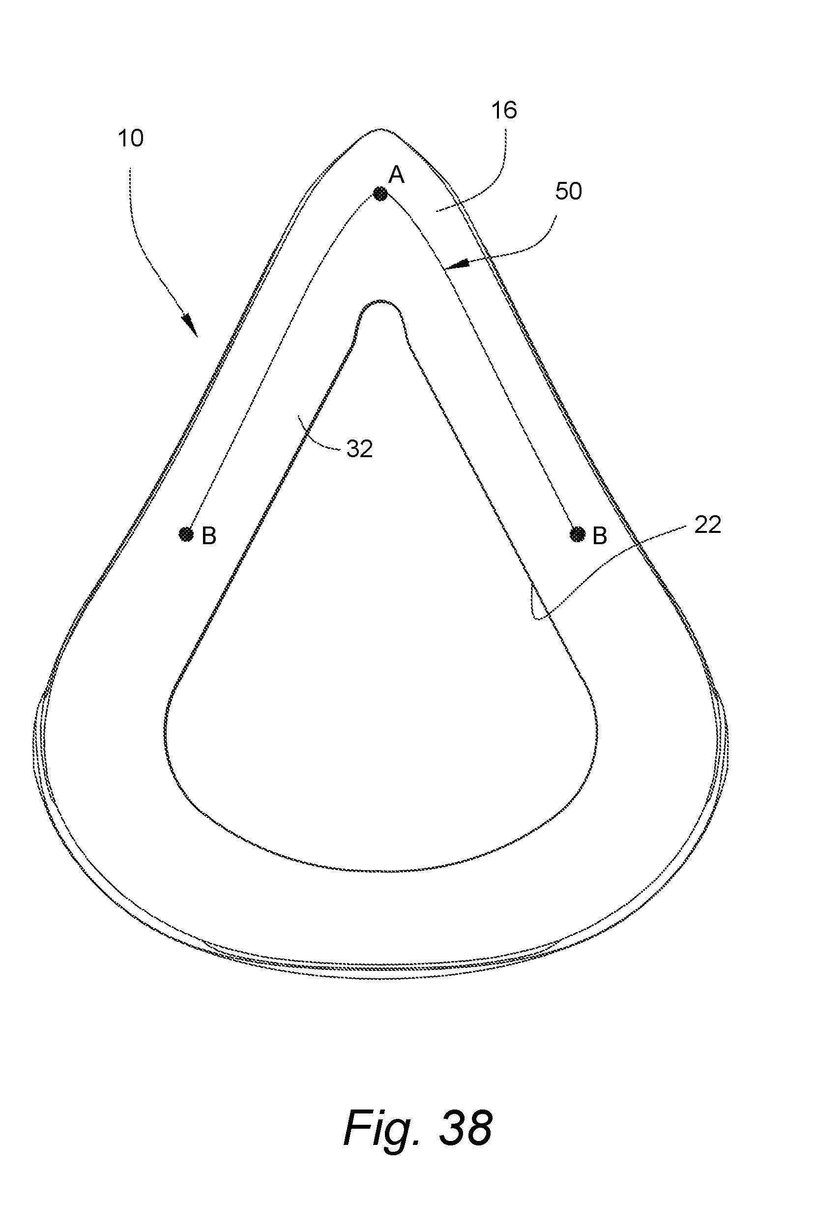
D00023

D00024
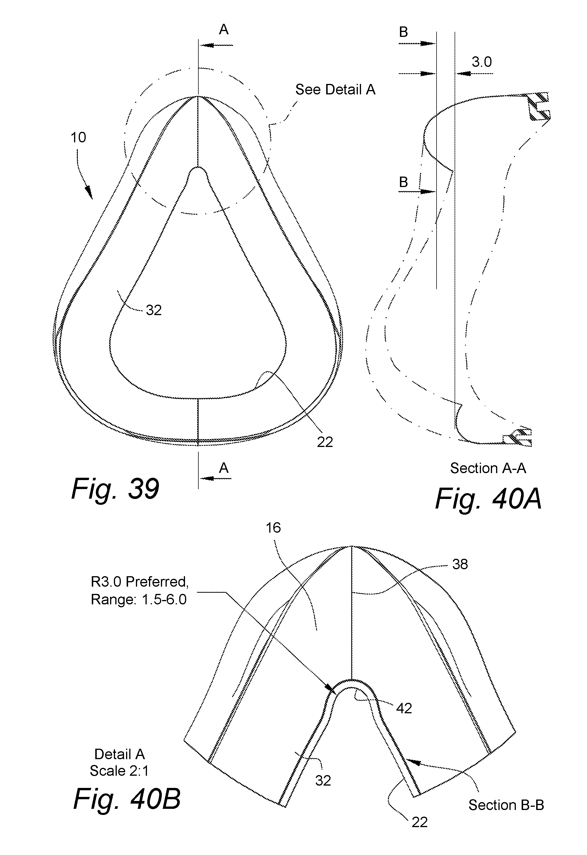
D00025

D00026

D00027

D00028

D00029

D00030

D00031

D00032

D00033

D00034

D00035

D00036

D00037

D00038

D00039

D00040

D00041

D00042

D00043

D00044

D00045

D00046
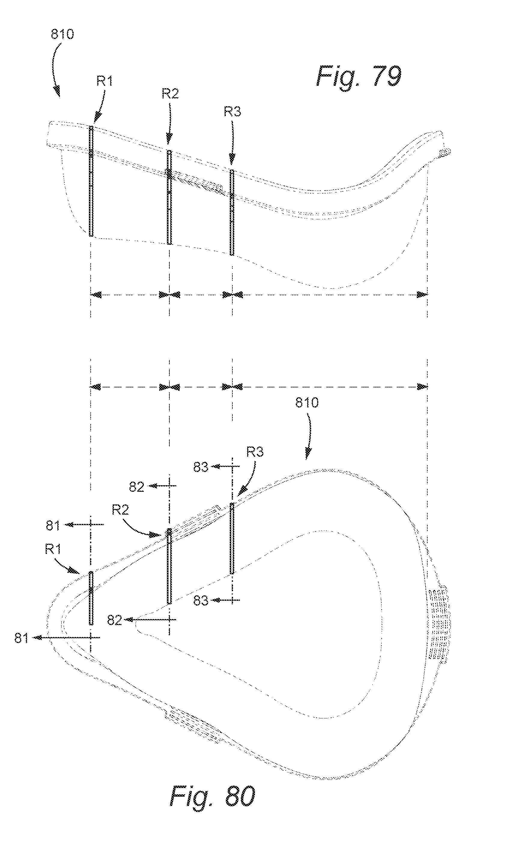
D00047

D00048

D00049
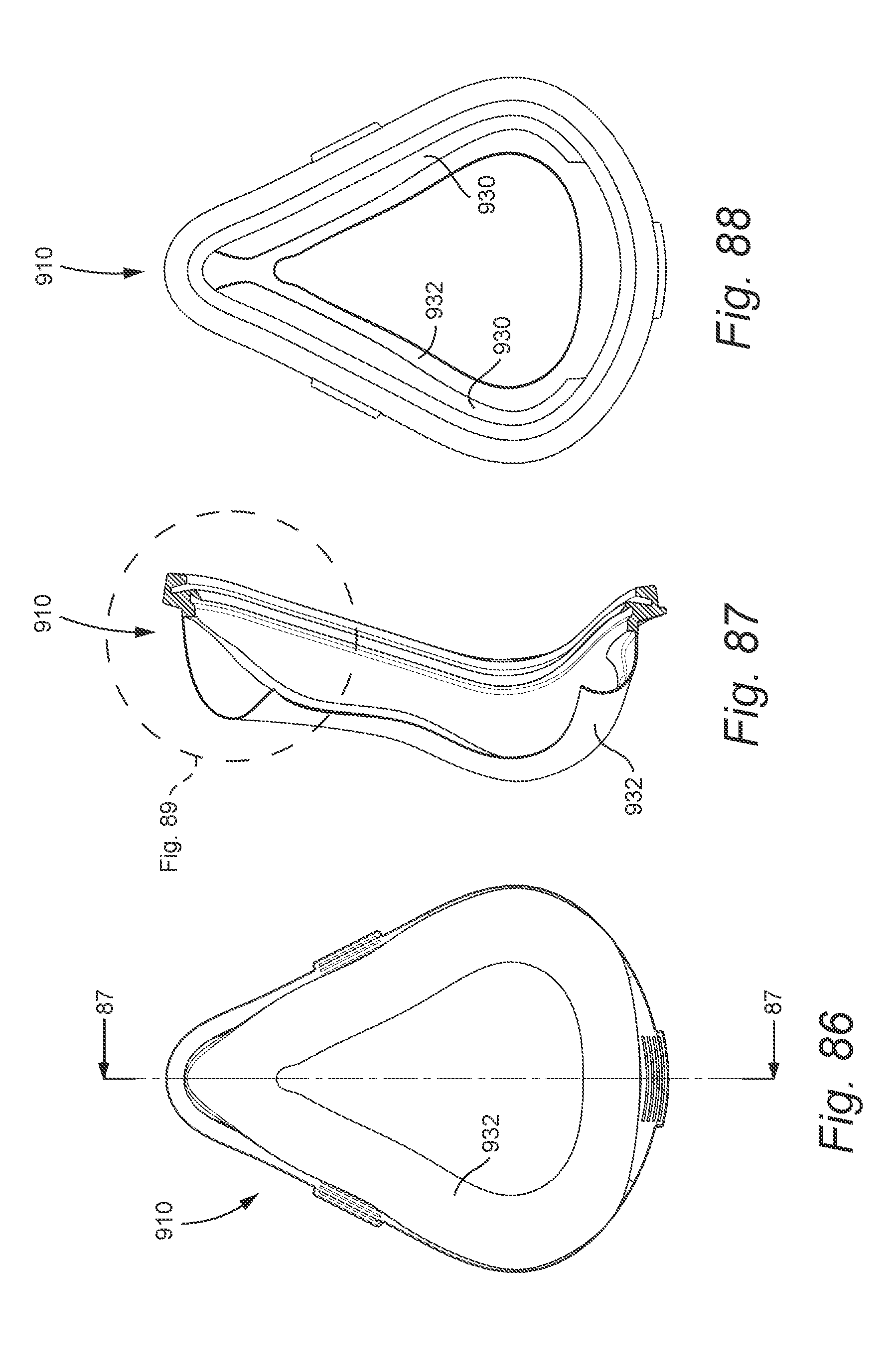
D00050

D00051
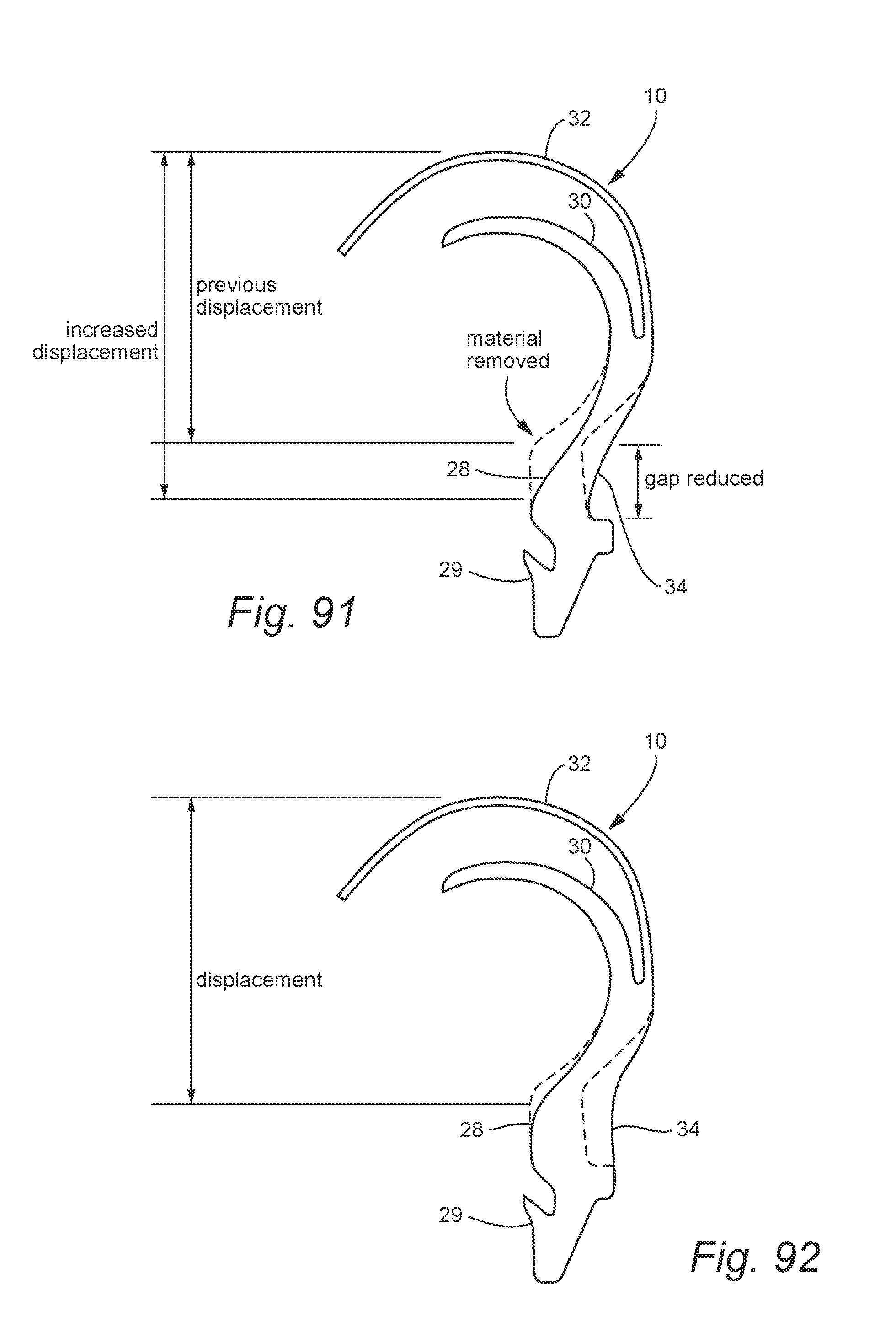
D00052

D00053

D00054
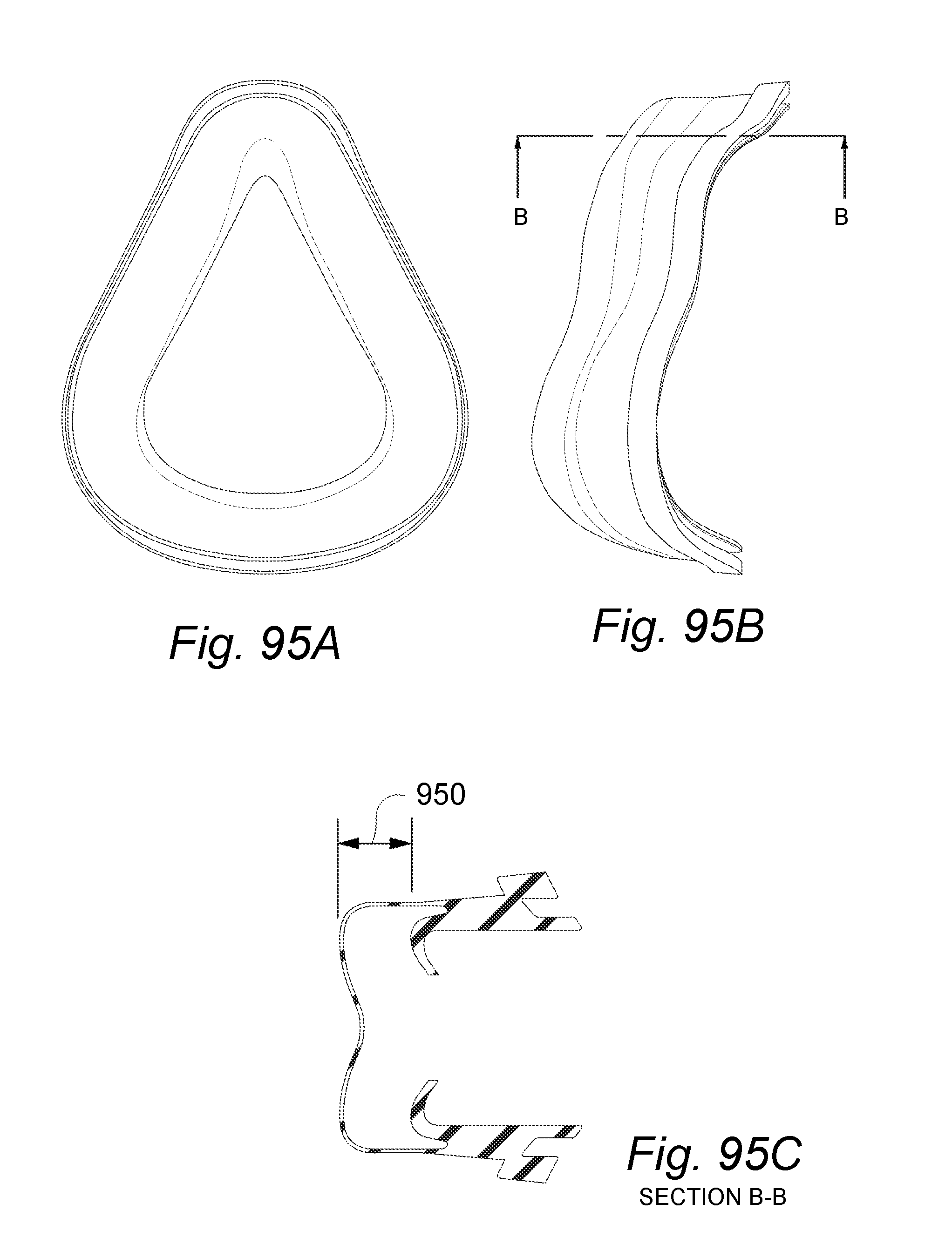
XML
uspto.report is an independent third-party trademark research tool that is not affiliated, endorsed, or sponsored by the United States Patent and Trademark Office (USPTO) or any other governmental organization. The information provided by uspto.report is based on publicly available data at the time of writing and is intended for informational purposes only.
While we strive to provide accurate and up-to-date information, we do not guarantee the accuracy, completeness, reliability, or suitability of the information displayed on this site. The use of this site is at your own risk. Any reliance you place on such information is therefore strictly at your own risk.
All official trademark data, including owner information, should be verified by visiting the official USPTO website at www.uspto.gov. This site is not intended to replace professional legal advice and should not be used as a substitute for consulting with a legal professional who is knowledgeable about trademark law.