Systems and methods for bulk material storage and/or transport
Harris Ja
U.S. patent number 10,538,381 [Application Number 13/625,675] was granted by the patent office on 2020-01-21 for systems and methods for bulk material storage and/or transport. This patent grant is currently assigned to SANDBOX LOGISTICS, LLC. The grantee listed for this patent is SandBox Logistics, LLC. Invention is credited to Robert A. Harris.


View All Diagrams
| United States Patent | 10,538,381 |
| Harris | January 21, 2020 |
Systems and methods for bulk material storage and/or transport
Abstract
Bulk material storage units that can be placed on flatbeds that can be hauled in various manners, including rail cars or trucks, to the destination and removed from the flatbed for temporary storage at the destination, freeing the transportation mode, e.g., rail cars or trucks, to be used elsewhere. Embodiments of the bulk material storage unit of the present invention replace rail hopper cars or truck trailers to hold the bulk material during transportation as well as provide temporary storage at the desired location, e.g., the origin or destination, without tying up transportation resources.
| Inventors: | Harris; Robert A. (Arlington, TX) | ||||||||||
|---|---|---|---|---|---|---|---|---|---|---|---|
| Applicant: |
|
||||||||||
| Assignee: | SANDBOX LOGISTICS, LLC
(Houston, TX) |
||||||||||
| Family ID: | 50337688 | ||||||||||
| Appl. No.: | 13/625,675 | ||||||||||
| Filed: | September 24, 2012 |
Prior Publication Data
| Document Identifier | Publication Date | |
|---|---|---|
| US 20140083554 A1 | Mar 27, 2014 | |
Related U.S. Patent Documents
| Application Number | Filing Date | Patent Number | Issue Date | ||
|---|---|---|---|---|---|
| 61538616 | Sep 23, 2011 | ||||
| Current U.S. Class: | 1/1 |
| Current CPC Class: | B65D 88/30 (20130101); B65D 90/54 (20130101); B65G 57/02 (20130101); B65D 88/54 (20130101); B65D 88/32 (20130101); B65G 67/02 (20130101); B65D 90/20 (20130101); B65D 90/0033 (20130101); B65B 1/06 (20130101); B65G 2201/0235 (20130101) |
| Current International Class: | B65D 88/30 (20060101); B65D 90/54 (20060101); B65G 57/02 (20060101); B65G 67/02 (20060101); B65D 90/00 (20060101); B65D 90/20 (20060101); B65D 88/54 (20060101); B65D 88/32 (20060101); B65B 1/06 (20060101) |
| Field of Search: | ;141/286,231 ;414/328 ;52/197 ;222/166 ;206/598 ;239/504 |
References Cited [Referenced By]
U.S. Patent Documents
| 137871 | April 1873 | Worsley |
| 150894 | May 1874 | Safely |
| 384443 | June 1888 | Hoover |
| 448238 | March 1891 | Johnson |
| 710611 | October 1902 | Ray |
| 711632 | October 1902 | Johnson |
| 917649 | April 1909 | Otto |
| 1143641 | June 1915 | McGregor |
| 1331883 | February 1920 | Stuart |
| 1344768 | June 1920 | Messiter |
| 1434488 | November 1922 | Forsythe et al. |
| 1520560 | December 1923 | Burno |
| 1506936 | September 1924 | Lea |
| 1526527 | February 1925 | Butler |
| 1573664 | February 1926 | Wetherill |
| 1807447 | May 1931 | Smith |
| 1850000 | March 1932 | Fernand |
| 1932320 | October 1933 | Steward |
| 1973312 | September 1934 | Hardinge |
| 2020628 | November 1935 | Woodruff |
| 2233005 | February 1941 | Garlinghouse |
| 2255448 | September 1941 | Morris |
| 2293160 | August 1942 | Miller |
| 2368672 | February 1945 | McNamara |
| 2381103 | August 1945 | Frank |
| 2385245 | September 1945 | Willoughby |
| 2413661 | December 1946 | Stokes |
| 2423879 | July 1947 | De Frees |
| 2563470 | August 1951 | Kane |
| 2564020 | August 1951 | Mengel |
| 2603342 | July 1952 | Martinson |
| 2616758 | November 1952 | Meyers |
| 2622771 | December 1952 | Tulou |
| 2652174 | September 1953 | Shea et al. |
| 2670866 | March 1954 | Glesby |
| 2678145 | May 1954 | Ejuzwiak et al. |
| 2693282 | November 1954 | Sensibar |
| 2700574 | January 1955 | Tourneau |
| 2792262 | April 1955 | Hathorn |
| 2774515 | December 1956 | Johansson et al. |
| 2791973 | May 1957 | Dorey |
| 2801125 | July 1957 | Page et al. |
| 2808164 | October 1957 | Glendinning |
| 2812970 | November 1957 | Martinson |
| 2837369 | June 1958 | Stopps |
| 2865521 | December 1958 | Fisher et al. |
| 2873036 | February 1959 | Noble |
| 2894666 | July 1959 | Campbell, Jr. |
| 2988235 | June 1961 | Ronyak |
| 2994460 | August 1961 | Matthews |
| 3041113 | June 1962 | Sackett |
| 3049248 | August 1962 | Heltzel et al. |
| 3064832 | November 1962 | Heltzel |
| 3083879 | April 1963 | Coleman |
| 3090527 | May 1963 | Rensch |
| 3109389 | November 1963 | Karlsson |
| 3122258 | February 1964 | Raymond |
| 3134606 | May 1964 | Oyler |
| 3135432 | June 1964 | McKinney |
| 3163127 | December 1964 | Gutridge et al. |
| 3187684 | June 1965 | Ortner |
| 3198494 | August 1965 | Curran et al. |
| 3199585 | August 1965 | Cronberger |
| 3248026 | April 1966 | Kemp |
| 3255927 | June 1966 | Ruppert et al. |
| 3265443 | August 1966 | Simas |
| 3270921 | September 1966 | Nadolske et al. |
| 3281006 | October 1966 | Wei |
| 3294306 | December 1966 | Areddy |
| 3318473 | May 1967 | Jones et al. |
| 3326572 | June 1967 | Murray |
| 3343688 | September 1967 | Ross |
| 3353599 | November 1967 | Swift |
| 3354918 | November 1967 | Coleman |
| 3378152 | April 1968 | Warner |
| 3387570 | June 1968 | Pulcrano et al. |
| 3396675 | August 1968 | Stevens |
| 3397654 | August 1968 | Snyder |
| 3406995 | October 1968 | McCarthy |
| 3407971 | October 1968 | Oehler |
| 3425599 | February 1969 | Sammarco et al. |
| 3455474 | July 1969 | Truncali |
| 3476270 | November 1969 | Cox et al. |
| 3486787 | December 1969 | Campbell |
| 3499694 | March 1970 | Coppel |
| 3508762 | April 1970 | Pratt |
| 3524567 | August 1970 | Coleman |
| 3528570 | September 1970 | Pase |
| 3561633 | February 1971 | Morrison et al. |
| 3587834 | June 1971 | Dugge |
| 3596609 | August 1971 | Ortner |
| 3601244 | August 1971 | Ort et al. |
| 3602400 | August 1971 | Cooke |
| 3650567 | March 1972 | Danielson |
| 3653521 | April 1972 | Bridge |
| 3661293 | May 1972 | Gerhard et al. |
| 3692363 | September 1972 | Tenebaum et al. |
| 3704797 | December 1972 | Suykens |
| 3721199 | March 1973 | Hassenauer |
| 3729121 | April 1973 | Cannon |
| 3734215 | May 1973 | Smith |
| 3738511 | June 1973 | Lemon et al. |
| 3752511 | August 1973 | Racy |
| 3777909 | December 1973 | Rheinfrank |
| 3785534 | January 1974 | Smith |
| 3800712 | April 1974 | Krug, Jr. |
| 3802584 | April 1974 | Sackett |
| 3817261 | June 1974 | Rogge |
| 3820762 | June 1974 | Bostrom et al. |
| 3827578 | August 1974 | Hough |
| 3840141 | October 1974 | Allom et al. |
| 3854612 | December 1974 | Snape |
| 3861716 | January 1975 | Baxter et al. |
| 3868028 | February 1975 | Mausser |
| 3883005 | May 1975 | Stevens |
| 3904105 | September 1975 | Booth |
| 3909223 | September 1975 | Schmidt |
| 3913933 | October 1975 | Visser et al. |
| 3933100 | January 1976 | Dugge |
| 3963149 | June 1976 | Fassauer |
| 3970123 | July 1976 | Poulton et al. |
| 3986708 | October 1976 | Hellzel et al. |
| 3997089 | December 1976 | Clarke et al. |
| 3999290 | December 1976 | Wood |
| 4003301 | January 1977 | Norton |
| 4004700 | January 1977 | Empey |
| 4019635 | April 1977 | Boots |
| 4057153 | November 1977 | Weaver |
| 4058239 | November 1977 | Van Mill |
| 4063656 | December 1977 | Lambert |
| 4073410 | February 1978 | Melcher |
| 4125195 | November 1978 | Sasadi |
| 4138163 | February 1979 | Calvert et al. |
| 4178117 | December 1979 | Brugler |
| 4204773 | May 1980 | Bates |
| 4210273 | July 1980 | Hegele |
| 4210963 | July 1980 | Ricciardi et al. |
| RE30358 | August 1980 | Sensibar |
| 4222498 | September 1980 | Brock |
| 4227732 | October 1980 | Kish |
| 4232884 | November 1980 | DeWitt |
| 4239424 | December 1980 | Pavolka |
| 4245820 | January 1981 | Muryn |
| 4247228 | January 1981 | Gray et al. |
| 4247370 | January 1981 | Nijhawan et al. |
| 4253612 | March 1981 | Schulze |
| 4258953 | March 1981 | Johnson |
| 4265266 | May 1981 | Kierbow et al. |
| 4272028 | June 1981 | Cobb |
| 4278190 | July 1981 | Oory et al. |
| 4280640 | July 1981 | Daloisio |
| 4282988 | August 1981 | Hulbert, Jr. |
| 4287921 | September 1981 | Sanford |
| 4287997 | September 1981 | Rolfe et al. |
| 4289353 | September 1981 | Merritt |
| 4299597 | November 1981 | Oetiker et al. |
| 4306895 | December 1981 | Thompson et al. |
| 4329106 | May 1982 | Adler |
| 4350241 | September 1982 | Wenzel |
| 4359176 | November 1982 | Johnson |
| 4363396 | December 1982 | Wolf et al. |
| 4395052 | July 1983 | Rash |
| 4397406 | August 1983 | Croley |
| 4398653 | August 1983 | Daloisio |
| 4402392 | September 1983 | Fabian et al. |
| 4407202 | October 1983 | McCormick |
| 4408886 | October 1983 | Sampson et al. |
| 4410106 | October 1983 | Kierbow et al. |
| 4420285 | December 1983 | Loyer et al. |
| 4427133 | January 1984 | Kierbow et al. |
| 4428504 | January 1984 | Bassett et al. |
| 4449861 | May 1984 | Saito et al. |
| 4453645 | June 1984 | Usui et al. |
| 4474204 | October 1984 | West |
| 4475672 | October 1984 | Whitehead |
| 4478155 | October 1984 | Cena et al. |
| 4483462 | November 1984 | Heintz |
| 4513755 | April 1985 | Baroni |
| 4525071 | June 1985 | Horowitz |
| 4526353 | July 1985 | Stomp |
| 4532098 | July 1985 | Campbell |
| 4534869 | August 1985 | Seibert |
| 4552573 | November 1985 | Weis |
| 4569394 | February 1986 | Sweatman et al. |
| 4570967 | February 1986 | Allnut |
| 4571143 | February 1986 | Hellerich |
| 4588605 | May 1986 | Frei et al. |
| 4608931 | September 1986 | Ruhmann et al. |
| 4619531 | October 1986 | Dunstan |
| 4624729 | November 1986 | Bresciani et al. |
| 4626155 | December 1986 | Hlinsky et al. |
| 4626166 | December 1986 | Jolly |
| 4628825 | December 1986 | Taylor et al. |
| 4639015 | January 1987 | Pitts |
| 4648584 | March 1987 | Wamser |
| 4660733 | April 1987 | Snyder et al. |
| 4701095 | October 1987 | Berryman et al. |
| 4714010 | December 1987 | Smart |
| 4715754 | December 1987 | Scully |
| 4724976 | February 1988 | Lee |
| 4738774 | April 1988 | Patrick |
| 4741273 | May 1988 | Sherwood |
| 4745952 | May 1988 | French |
| 4761039 | August 1988 | Hilaris |
| 4779751 | October 1988 | Munroe |
| 4798039 | January 1989 | Deglise |
| 4801389 | January 1989 | Brannon et al. |
| 4819830 | April 1989 | Schultz |
| 4836510 | June 1989 | Weber et al. |
| 4836735 | June 1989 | Dennehy |
| 4848605 | July 1989 | Wise |
| 4882784 | November 1989 | Tump |
| 4889219 | December 1989 | Key |
| 4901649 | February 1990 | Fehrenbach et al. |
| 4909378 | March 1990 | Webb |
| 4909556 | March 1990 | Koskinen |
| 4917019 | April 1990 | Hesch et al. |
| 4919583 | April 1990 | Speakman, Jr. |
| 4923358 | May 1990 | Van Mill |
| 4946068 | August 1990 | Erickson et al. |
| 4947760 | August 1990 | Dawson et al. |
| 4949714 | August 1990 | Orr |
| 4954975 | September 1990 | Kalata |
| 4956821 | September 1990 | Fenelon |
| 4964243 | October 1990 | Reiter |
| 4975205 | December 1990 | Sloan |
| 4975305 | December 1990 | Biginelli |
| 4988115 | January 1991 | Steinke |
| 4995522 | February 1991 | Barr |
| 5004400 | April 1991 | Handke |
| 5028002 | July 1991 | Whitford |
| 5036979 | August 1991 | Selz |
| 5042538 | August 1991 | Wiese |
| 5069352 | December 1991 | Harbolt et al. |
| 5080259 | January 1992 | Hadley |
| 5082304 | January 1992 | Preller |
| 5102281 | April 1992 | Handke |
| 5102286 | April 1992 | Fenton |
| 5105858 | April 1992 | Levinson |
| 5131524 | July 1992 | Uehara |
| 5167719 | December 1992 | Tamaki |
| 5190182 | March 1993 | Copas et al. |
| 5195861 | March 1993 | Handke |
| 5199826 | April 1993 | Lawrence |
| 5201546 | April 1993 | Lindsay |
| 5224635 | July 1993 | Wise |
| 5253746 | October 1993 | Friesen et al. |
| 5253776 | October 1993 | Decroix et al. |
| 5265763 | November 1993 | Heinrici et al. |
| 5277014 | January 1994 | White |
| 5280883 | January 1994 | Ibar |
| 5286158 | February 1994 | Zimmerman |
| 5286294 | February 1994 | Ebi et al. |
| 5290139 | March 1994 | Hedrick |
| 5317783 | June 1994 | Williamson |
| 5320046 | June 1994 | Hesch |
| 5324097 | June 1994 | DeCap |
| 5339996 | August 1994 | Dubbert |
| 5345982 | September 1994 | Nadeau et al. |
| 5358137 | October 1994 | Shuert et al. |
| 5373792 | December 1994 | Pileggi et al. |
| 5392946 | February 1995 | Holbrook et al. |
| 5402915 | April 1995 | Hogan |
| 5413154 | May 1995 | Hurst et al. |
| 5429259 | July 1995 | Robin |
| 5441321 | August 1995 | Karpisek |
| 5445289 | August 1995 | Owen |
| 5465829 | November 1995 | Kruse |
| 5470175 | November 1995 | Jensen et al. |
| 5470176 | November 1995 | Corcoran et al. |
| 5493852 | February 1996 | Stewart |
| 5498119 | March 1996 | Faivre |
| 5507514 | April 1996 | Jacques |
| 5538286 | July 1996 | Hoff |
| 5549278 | August 1996 | Sidler |
| 5564599 | October 1996 | Barber et al. |
| 5570743 | November 1996 | Padgett et al. |
| 5590976 | January 1997 | Kilheffer et al. |
| 5601181 | February 1997 | Lindhorst |
| 5602761 | February 1997 | Spoerre et al. |
| 5613446 | March 1997 | DiLuigi et al. |
| 5617974 | April 1997 | Sawyer |
| 5647514 | July 1997 | Toth et al. |
| RE35580 | August 1997 | Heider et al. |
| 5667298 | September 1997 | Musil |
| 5687881 | November 1997 | Rouse et al. |
| 5690466 | November 1997 | Gaddis et al. |
| 5697535 | December 1997 | Coleman |
| 5706614 | January 1998 | Wiley et al. |
| 5718555 | February 1998 | Swalheim |
| 5722552 | March 1998 | Olson |
| 5722688 | March 1998 | Garcia |
| 5746258 | May 1998 | Huck |
| 5761854 | June 1998 | Johnson et al. |
| 5762222 | June 1998 | Liu |
| 5772390 | June 1998 | Walker |
| 5782524 | July 1998 | Heider et al. |
| 5785421 | July 1998 | Milek |
| 5803296 | September 1998 | Olson |
| 5806863 | September 1998 | Heger et al. |
| 5836480 | November 1998 | Epp et al. |
| 5845799 | December 1998 | Deaton |
| 5876172 | March 1999 | Di Rosa |
| 5878903 | March 1999 | Ung |
| 5906471 | May 1999 | Schwoerer |
| 5911337 | June 1999 | Bedeker |
| 5924829 | July 1999 | Hastings |
| 5927558 | July 1999 | Bruce |
| 5960974 | October 1999 | Kee |
| 5971219 | October 1999 | Karpisek |
| 5993202 | November 1999 | Yamazaki et al. |
| 5997099 | December 1999 | Collins |
| 6002063 | December 1999 | Bilak et al. |
| 6006918 | December 1999 | Hart |
| 6069118 | May 2000 | Hinkel et al. |
| 6077068 | June 2000 | Okumura |
| 6092974 | July 2000 | Roth |
| 6109486 | August 2000 | Lee |
| 6120233 | September 2000 | Adam |
| D431358 | October 2000 | Willemsen |
| 6155175 | December 2000 | Rude et al. |
| 6186654 | February 2001 | Gunteret et al. |
| 6190107 | February 2001 | Lanigan et al. |
| 6192985 | February 2001 | Hinkel et al. |
| 6196590 | March 2001 | Kim |
| 6205938 | March 2001 | Foley et al. |
| 6210088 | April 2001 | Crosby |
| 6231284 | May 2001 | Kordel |
| 6247594 | June 2001 | Garton |
| 6263803 | July 2001 | Dohr et al. |
| 6269849 | August 2001 | Fields |
| 6273154 | August 2001 | Laug |
| 6283212 | September 2001 | Hinkel et al. |
| 6286986 | September 2001 | Grimland |
| 6296109 | October 2001 | Nohl |
| 6306800 | October 2001 | Samuel et al. |
| 6328156 | December 2001 | Otsman |
| 6328183 | December 2001 | Coleman |
| 6364584 | April 2002 | Taylor |
| 6374915 | April 2002 | Andrews |
| 6382446 | May 2002 | Hinkle et al. |
| 6390742 | May 2002 | Breeden |
| 6401983 | June 2002 | McDonald et al. |
| 6412422 | July 2002 | Dohr et al. |
| 6415909 | July 2002 | Mitchell et al. |
| 6416271 | July 2002 | Pigott et al. |
| 6422413 | July 2002 | Hall et al. |
| 6425725 | July 2002 | Ehlers |
| 6450522 | September 2002 | Yamada et al. |
| 6457291 | October 2002 | Wick |
| 6498976 | December 2002 | Ehlbeck et al. |
| 6505760 | January 2003 | Werner |
| 6508387 | January 2003 | Simon et al. |
| 6508615 | January 2003 | Taylor |
| 6523482 | February 2003 | Wingate |
| 6537002 | March 2003 | Gloystein |
| 6557896 | May 2003 | Stobart |
| 6575614 | June 2003 | Tosco et al. |
| 6660693 | December 2003 | Miller et al. |
| 6663373 | December 2003 | Yoshida |
| 6666573 | December 2003 | Grassi |
| 6675066 | January 2004 | Moshgbar |
| 6675073 | January 2004 | Kieman et al. |
| 6705449 | March 2004 | Wagstaffe |
| 6720290 | April 2004 | England et al. |
| 6772912 | August 2004 | Schall et al. |
| 6774318 | August 2004 | Beal et al. |
| 6776235 | August 2004 | England |
| 6783032 | August 2004 | Fons |
| 6811048 | November 2004 | Lau |
| 6828280 | December 2004 | England et al. |
| 6835041 | December 2004 | Albert |
| 6882960 | April 2005 | Miller |
| 6902061 | June 2005 | Elstone |
| 6915854 | July 2005 | England et al. |
| 6953119 | October 2005 | Wening |
| 6955127 | October 2005 | Taylor |
| 6964551 | November 2005 | Friesen |
| 6968946 | November 2005 | Shuert |
| 6974021 | December 2005 | Boevers |
| 7008163 | March 2006 | Russell |
| 7051661 | May 2006 | Herzog et al. |
| 7084095 | August 2006 | Lee et al. |
| 7104425 | September 2006 | Le Roy |
| 7140516 | November 2006 | Bothor |
| 7146914 | December 2006 | Morton et al. |
| 7201290 | April 2007 | Mehus et al. |
| 7214028 | May 2007 | Boasso |
| 7240681 | July 2007 | Salk |
| 7252309 | August 2007 | Eng Soon et al. |
| 7284579 | October 2007 | Elgan et al. |
| 7284670 | October 2007 | Schmid |
| 7316333 | January 2008 | Wegner |
| 7367271 | May 2008 | Early |
| 7377219 | May 2008 | Brandt |
| 7410623 | August 2008 | Mehus et al. |
| 7475796 | January 2009 | Garton |
| 7500817 | March 2009 | Furrer et al. |
| 7513280 | April 2009 | Brashears et al. |
| 7591386 | September 2009 | Hooper |
| 7640075 | December 2009 | Wietgrefe |
| 7695538 | April 2010 | Cheng |
| 7753637 | July 2010 | Benedict et al. |
| 7798558 | September 2010 | Messier |
| 7802958 | September 2010 | Garcia et al. |
| 7803321 | September 2010 | Lark et al. |
| 7837427 | November 2010 | Beckel |
| 7841394 | November 2010 | McNeel et al. |
| 7845516 | December 2010 | Pessin et al. |
| 7858888 | December 2010 | Lucas et al. |
| 7867613 | January 2011 | Smith |
| 7891304 | February 2011 | Herzog et al. |
| 7891523 | February 2011 | Mehus et al. |
| 7896198 | March 2011 | Mehus et al. |
| 7921783 | April 2011 | Forbes et al. |
| 7967161 | June 2011 | Townsend |
| 7980803 | July 2011 | Brandstatter et al. |
| 7997213 | August 2011 | Gauthier et al. |
| 7997623 | August 2011 | Williams |
| 8083083 | December 2011 | Mohns |
| 8201520 | June 2012 | Meritt |
| 8313278 | November 2012 | Simmons et al. |
| 8366349 | February 2013 | Beachner |
| 8375690 | February 2013 | LaFargue et al. |
| 8379927 | February 2013 | Taylor |
| 8387824 | March 2013 | Wietgrefe |
| 8393502 | March 2013 | Renyer et al. |
| 8424666 | April 2013 | Berning et al. |
| 8469065 | June 2013 | Schroeder et al. |
| D688351 | August 2013 | Oren |
| 8505780 | August 2013 | Oren |
| 8544419 | October 2013 | Spalding et al. |
| 8545148 | October 2013 | Wanek-Pusset et al. |
| 8562022 | October 2013 | Nadeau et al. |
| 8573387 | November 2013 | Trimble |
| 8573917 | November 2013 | Renyer |
| 8585341 | November 2013 | Oren |
| D694670 | December 2013 | Oren |
| 8616370 | December 2013 | Allegretti |
| 8622251 | January 2014 | Oren |
| 8636832 | January 2014 | Stutzman et al. |
| 8646641 | February 2014 | Moir |
| 8662525 | March 2014 | Dierks et al. |
| 8668430 | March 2014 | Oren |
| D703582 | April 2014 | Oren |
| 8689840 | April 2014 | Yang et al. |
| 8820559 | September 2014 | Beitler et al. |
| 8827118 | September 2014 | Oren |
| 8881749 | November 2014 | Smith |
| 8887914 | November 2014 | Allegretti |
| 8905266 | December 2014 | De Brabanter |
| 8915691 | December 2014 | Mintz |
| 9051801 | June 2015 | Mintz |
| 9052034 | June 2015 | Wegner et al. |
| D740556 | October 2015 | Huber |
| 9162261 | October 2015 | Smith |
| 9267266 | February 2016 | Cutler et al. |
| 9296572 | March 2016 | Houghton et al. |
| 9309064 | April 2016 | Sheesley |
| 9410414 | August 2016 | Tudor |
| D780883 | March 2017 | Schaffner et al. |
| D783771 | April 2017 | Stegemoeller et al. |
| D783772 | April 2017 | Stegemoeller, III et al. |
| 9624036 | April 2017 | Luharuka et al. |
| 9688492 | June 2017 | Stutzman et al. |
| 9796318 | October 2017 | Nolasco |
| 2001/0022308 | September 2001 | Epp et al. |
| 2001/0038777 | November 2001 | Cassell |
| 2001/0045338 | November 2001 | Ransil et al. |
| 2002/0134550 | September 2002 | Leeson et al. |
| 2002/0139643 | October 2002 | Peltier et al. |
| 2003/0006248 | January 2003 | Gill et al. |
| 2003/0024971 | February 2003 | Jones |
| 2003/0111470 | June 2003 | Fouillet et al. |
| 2003/0145418 | August 2003 | Ikeda et al. |
| 2003/0156929 | August 2003 | Russell |
| 2004/0065699 | April 2004 | Schoer et al. |
| 2004/0074922 | April 2004 | Bother et al. |
| 2004/0084874 | May 2004 | McDougall et al. |
| 2004/0206646 | October 2004 | Goh |
| 2004/0245284 | December 2004 | Mehus et al. |
| 2005/0158158 | July 2005 | Porta |
| 2005/0201851 | September 2005 | Jonkka |
| 2006/0012183 | January 2006 | Marchiori et al. |
| 2006/0027582 | February 2006 | Beach |
| 2006/0053582 | March 2006 | Engel et al. |
| 2006/0091072 | May 2006 | Schmid et al. |
| 2006/0151058 | July 2006 | Salaoras et al. |
| 2006/0180062 | August 2006 | Furrer et al. |
| 2006/0180232 | August 2006 | Glewwe et al. |
| 2006/0239806 | October 2006 | Yelton |
| 2006/0267377 | November 2006 | Lusk et al. |
| 2006/0277783 | December 2006 | Garton |
| 2006/0289166 | December 2006 | Stromquist et al. |
| 2007/0096537 | May 2007 | Hicks |
| 2007/0125543 | June 2007 | McNeel et al. |
| 2007/0194564 | August 2007 | Garceau et al. |
| 2008/0008562 | January 2008 | Beckel et al. |
| 2008/0029546 | February 2008 | Shuld |
| 2008/0029553 | February 2008 | Culleton |
| 2008/0058228 | March 2008 | Wilson |
| 2008/0017905 | July 2008 | McGough et al. |
| 2008/0179054 | July 2008 | McGough et al. |
| 2008/0179324 | July 2008 | McGough et al. |
| 2008/0213073 | September 2008 | Benedict et al. |
| 2008/0226434 | September 2008 | Smith et al. |
| 2008/0264641 | October 2008 | Slabaugh et al. |
| 2008/0277423 | November 2008 | Garton |
| 2008/0315558 | December 2008 | Cesterino |
| 2009/0038242 | February 2009 | Cope |
| 2009/0078410 | March 2009 | Krenek et al. |
| 2009/0223143 | September 2009 | Esposito |
| 2009/0278326 | November 2009 | Rowland et al. |
| 2010/0021258 | January 2010 | Kim |
| 2010/0037572 | February 2010 | Cheng |
| 2010/0038143 | February 2010 | Burnett et al. |
| 2010/0040446 | February 2010 | Renyer |
| 2010/0065466 | March 2010 | Perkins |
| 2010/0072308 | March 2010 | Hermann et al. |
| 2010/0080681 | April 2010 | Bain |
| 2010/0108711 | May 2010 | Wietgrefe |
| 2010/0129193 | May 2010 | Sherrer |
| 2010/0199668 | August 2010 | Coustou et al. |
| 2010/0207371 | August 2010 | Van Houdt et al. |
| 2010/0278621 | November 2010 | Redekop |
| 2010/0288603 | November 2010 | Schafer |
| 2010/0320727 | December 2010 | Haut et al. |
| 2011/0011893 | January 2011 | Cerny |
| 2011/0017693 | January 2011 | Thomas |
| 2011/0101040 | May 2011 | Weissbrod |
| 2011/0109703 | May 2011 | Williams |
| 2011/0121003 | May 2011 | Moir |
| 2011/0127178 | June 2011 | Claussen |
| 2011/0160104 | June 2011 | Wu et al. |
| 2011/0162838 | July 2011 | Mackenzie et al. |
| 2011/0168593 | July 2011 | Neufeld et al. |
| 2011/0222983 | September 2011 | Dugic et al. |
| 2011/0297702 | December 2011 | Hildebrandt et al. |
| 2012/0017812 | January 2012 | Renyer |
| 2012/0090956 | April 2012 | Brobst |
| 2012/0103848 | May 2012 | Allegretti et al. |
| 2012/0219391 | August 2012 | Teichrob et al. |
| 2012/0247335 | October 2012 | Stutzman et al. |
| 2012/0255539 | October 2012 | Kolecki |
| 2013/0004272 | January 2013 | Mintz |
| 2013/0022441 | January 2013 | Uhryn et al. |
| 2013/0206415 | August 2013 | Sheesley |
| 2013/0209204 | August 2013 | Sheesley |
| 2013/0233545 | September 2013 | Mahoney |
| 2013/0284729 | October 2013 | Cook et al. |
| 2013/0309052 | November 2013 | Luharuka |
| 2013/0323005 | December 2013 | Rexius et al. |
| 2014/0020765 | January 2014 | Oren |
| 2014/0020892 | January 2014 | Oren |
| 2014/0023465 | January 2014 | Oren et al. |
| 2014/0034662 | February 2014 | Chalmers et al. |
| 2014/0044507 | February 2014 | Naizer et al. |
| 2014/0077484 | March 2014 | Harrell |
| 2014/0083554 | March 2014 | Harris |
| 2014/0093319 | April 2014 | Harris et al. |
| 2014/0097182 | April 2014 | Sheesley |
| 2014/0166647 | June 2014 | Sheesley |
| 2014/0202590 | July 2014 | Higgins |
| 2014/0203046 | July 2014 | Allegretti |
| 2014/0234059 | August 2014 | Thomeer |
| 2014/0305769 | October 2014 | Eiden et al. |
| 2014/0321950 | October 2014 | Krenek et al. |
| 2014/0377042 | December 2014 | McMahon |
| 2015/0004895 | January 2015 | Hammers et al. |
| 2015/0069052 | March 2015 | Allegretti et al. |
| 2015/0079890 | March 2015 | Stutzman et al. |
| 2015/0086307 | March 2015 | Stefan |
| 2015/0086308 | March 2015 | McIver et al. |
| 2015/0107822 | April 2015 | Tudor |
| 2015/0110565 | April 2015 | Harris |
| 2015/0115589 | April 2015 | Thiessen |
| 2015/0159232 | June 2015 | Zucchi et al. |
| 2015/0209829 | July 2015 | De Siqueira et al. |
| 2015/0284183 | October 2015 | Houghton et al. |
| 2016/0148813 | May 2016 | Rogers et al. |
| 2016/0177678 | June 2016 | Morris et al. |
| 2016/0185522 | June 2016 | Herman et al. |
| 2016/0273355 | September 2016 | Gosney et al. |
| 2016/0280480 | September 2016 | Smith et al. |
| 2017/0129721 | May 2017 | Harris et al. |
| 2017/0217353 | August 2017 | Vander Pol |
| 2018/0009401 | January 2018 | Miller et al. |
| 2023138 | Feb 1992 | CA | |||
| 2791088 | Mar 2013 | CA | |||
| 2037354 | May 1989 | CN | |||
| 2059909 | Aug 1990 | CN | |||
| 2075632 | Apr 1991 | CN | |||
| 1329562 | Jan 2002 | CN | |||
| 2517684 | Oct 2002 | CN | |||
| 1635965 | Jul 2005 | CN | |||
| 2913250 | Jun 2007 | CN | |||
| 201161588 | Dec 2008 | CN | |||
| 201390486 | Jan 2010 | CN | |||
| 101823630 | Sep 2010 | CN | |||
| 102101595 | Jun 2011 | CN | |||
| 201881469 | Jun 2011 | CN | |||
| 102114985 | Jul 2011 | CN | |||
| 203033469 | Jul 2013 | CN | |||
| 103350017 | Oct 2013 | CN | |||
| 203580948 | May 2014 | CN | |||
| 3108121 | Sep 1982 | DE | |||
| 3342281 | Jun 1985 | DE | |||
| 4008147 | Sep 1990 | DE | |||
| 4217329 | May 1993 | DE | |||
| 20317967 | Mar 2004 | DE | |||
| 0016977 | Oct 1980 | EP | |||
| 0019967 | Dec 1980 | EP | |||
| 322283 | Jun 1989 | EP | |||
| 0564969 | Oct 1993 | EP | |||
| 0997607 | May 2000 | EP | |||
| 1052194 | Nov 2000 | EP | |||
| 1167236 | Jan 2002 | EP | |||
| 1598288 | Nov 2005 | EP | |||
| 1775190 | Apr 2007 | EP | |||
| 1795467 | Jun 2007 | EP | |||
| 2062832 | May 2009 | EP | |||
| 2311757 | Apr 2011 | EP | |||
| 2173445 | Oct 1973 | FR | |||
| 2640598 | Jun 1990 | FR | |||
| 1000621 | Aug 1965 | GB | |||
| 1296736 | Nov 1972 | GB | |||
| 1333976 | Oct 1973 | GB | |||
| 2066220 | Jul 1981 | GB | |||
| 2204847 | Nov 1988 | GB | |||
| 2374864 | Oct 2002 | GB | |||
| S4871029 | Sep 1973 | JP | |||
| S4876041 | Sep 1973 | JP | |||
| S58161888 | Oct 1983 | JP | |||
| 410087046 | Apr 1998 | JP | |||
| 10264882 | Oct 1998 | JP | |||
| 11034729 | Feb 1999 | JP | |||
| 2007084151 | Apr 2007 | JP | |||
| 2012011046 | May 2013 | MX | |||
| 8105283 | Jun 1983 | NL | |||
| 1990008082 | Jul 1990 | WO | |||
| 1992002437 | Feb 1992 | WO | |||
| 1993001997 | Feb 1993 | WO | |||
| 1993006031 | Apr 1993 | WO | |||
| 1996025302 | Aug 1996 | WO | |||
| 2003024815 | Mar 2003 | WO | |||
| 2006039757 | Apr 2006 | WO | |||
| 2007005054 | Jan 2007 | WO | |||
| 2007057398 | May 2007 | WO | |||
| 2007061310 | May 2007 | WO | |||
| 2008012513 | Jan 2008 | WO | |||
| 2009087338 | Jul 2009 | WO | |||
| 2010026235 | Mar 2010 | WO | |||
| 2012021447 | Feb 2012 | WO | |||
| 2012058059 | May 2012 | WO | |||
| 2011099358 | Jun 2013 | WO | |||
Other References
|
Capt. Penny Ripperger, "119th Wing receives railcar donation", Jul. 9, 2008, Air Force Print News Today, pp. 1-2, [http://www.119wg.ang.af.mil/news/story_print.asp?id=123105964]. cited by examiner . FS-35 Desert Frac-Sanders. NOV (National Oilwell Varco). Mar. 19, 2012. (https://web.archive.org/web/20120319070423/http://www.nov.com/Well_Servi- ce_and_Completion/Frac_Sand_Handling_Equipment/Frac_Sanders/FS-35.aspx). cited by applicant . Frac Sand Primer by Brian D. Olmen, Kelrick, LLC, from Hydraulic Fracturing by Michael Berry Smith and Carl Montgomery (CRC Press, Dec. 16, 2015), p. 384. cited by applicant . Premier Silica LLC, Sands Application in the Energy Market, Irving, TX, Copyright 2016. cited by applicant . Getty, John, Montana Tech; ASTM International, Overview of Proppants and Existing Standards and Practices, Jacksonville, FL, Jan. 29, 2013. cited by applicant . Arrows Up, Inc., Jumbo BTS--Bulk Transport System, Aug. 1, 2014. cited by applicant . Arrows Up, Inc., Reusable Packaging Association, Member Spotlight: John Allegretti, President & CEO, Arrows Up, Inc., Jun. 23, 2016. cited by applicant . Seed Today, Arrows Up, Inc. Bulk Transport System (BTS), Country Journal Publishing Co., Decatur, IL, Mar. 2, 2011. cited by applicant . SeedQuest, Arrows Up, Inc. launches innovative bulk transport system for see, Barrington, IL, Mar. 2, 2011. cited by applicant . Monster Tanks, Inc., Sand Monster Website, http://monstertanksinc.com/sandmonster.html, 2012. cited by applicant . Solaris Oilfield Infrastructure, Mobile Sand Silo System, 2016. cited by applicant . Final Office Action dated Sep. 27, 2016 for co-pending U.S. Appl. No. 13/555,635. cited by applicant . Non-Final Office Action dated Mar. 23, 2016 for co-pending U.S. Appl. No. 13/555,635. cited by applicant . Final Office Action dated Jul. 30, 2015 for co-pending U.S. Appl. No. 13/555,635. cited by applicant . Non-Final Office Action dated Oct. 22, 2014 for co-pending U.S. Appl. No. 13/555,635. cited by applicant . Final Office Action dated Jun. 21, 2016 for co-pending U.S. Appl. No. 13/628,702. cited by applicant . Non-Final Office Action dated Feb. 23, 2016 for co-pending U.S. Appl. No. 13/628,702. cited by applicant . Final Office Action dated Sep. 22, 2015 for co-pending U.S. Appl. No. 13/628,702. cited by applicant . Non-Final Office Action dated Jul. 28, 2015 for co-pending U.S. Appl. No. 13/628,702. cited by applicant . Final Office Action dated Mar. 24, 2015 for co-pending U.S. Appl. No. 13/628,702. cited by applicant . Non-Final Office Action dated Sep. 18, 2014 for co-pending U.S. Appl. No. 13/628,702. cited by applicant . Final Office Action dated Jun. 27, 2016 for co-pending U.S. Appl. No. 14/831,924. cited by applicant . Non-Final Office Action dated Feb. 16, 2016 for co-pending U.S. Appl. No. 14/831,924. cited by applicant . Final Office Action dated Jun. 27, 2016 for co-pending U.S. Appl. No. 14/923,920. cited by applicant . Non-Final Office Action dated Feb. 9, 2016 for co-pending U.S. Appl. No. 14/923,920. cited by applicant . Final Office Action dated Sep. 15, 2016 for co-pending U.S. Appl. No. 14/943,111. cited by applicant . Non-Final Office Action dated Apr. 5, 2016 for co-pending U.S. Appl. No. 14/943,111. cited by applicant . Final Office Action dated Jul. 18, 2016 for co-pending U.S. Appl. No. 14/948,494. cited by applicant . Non-Final Office Action dated Apr. 8, 2016 for co-pending U.S. Appl. No. 14/948,494. cited by applicant . Non-Final Office Action dated Sep. 6, 2016 for co-pending U.S. Appl. No. 15/144,296. cited by applicant . Non-Final Office Action dated Jul. 25, 2016 for co-pending U.S. Appl. No. 13/660,855. cited by applicant . Final Office Action dated Apr. 28, 2016 for co-pending U.S. Appl. No. 13/660,855. cited by applicant . Non-Final Office Action dated Oct. 6, 2015 for co-pending U.S. Appl. No. 13/660,855. cited by applicant . Final Office Action dated Aug. 6, 2015 for co-pending U.S. Appl. No. 13/660,855. cited by applicant . Non-Final Office Action dated Apr. 29, 2015 for co-pending U.S. Appl. No. 13/660,855. cited by applicant . Final Office Action dated Dec. 17, 2014 for co-pending U.S. Appl. No. 13/660,855. cited by applicant . Non-Final Office Action dated Sep. 4, 2014 for co-pending U.S. Appl. No. 13/660,855. cited by applicant . Final Office Action dated Sep. 24, 2013 for co-pending U.S. Appl. No. 13/660,855. cited by applicant . Non-Final Office Action dated May 14, 2013 for co-pending U.S. Appl. No. 13/660,855. cited by applicant . Non-Final Office Action dated Jul. 5, 2016 for co-pending U.S. Appl. No. 14/996,362. cited by applicant . Non-Final Office Action dated Jul. 6, 2016 for co-pending U.S. Appl. No. 15/144,450. cited by applicant . Final Office Action dated Sep. 29, 2016 for co-pending U.S. Appl. No. 13/768,962. cited by applicant . Non-Final Office Action dated Apr. 5, 2016 for co-pending U.S. Appl. No. 13/768,962. cited by applicant . Final Office Action dated Oct. 9, 2015 for co-pending U.S. Appl. No. 13/768,962. cited by applicant . Non-Final Office Action dated May 1, 2015 for co-pending U.S. Appl. No. 13/768,962. cited by applicant . Non-Final Office Action dated Jul. 18, 2016 for co-pending U.S. Appl. No. 15/152,744. cited by applicant . Non-Final Office Action dated Apr. 13, 2016 for co-pending U.S. Appl. No. 14/738,485. cited by applicant . Non-Final Office Action dated Sep. 7, 2016 for co-pending U.S. Appl. No. 14/841,942. cited by applicant . Final Office Action dated May 12, 2016 for co-pending U.S. Appl. No. 14/841,942. cited by applicant . Non-Final Office Action dated Nov. 30, 2015 for co-pending U.S. Appl. No. 14/841,942. cited by applicant . Non-Final Office Action dated Jul. 21, 2016 for co-pending U.S. Appl. No. 15/083,596. cited by applicant . Non-Final Office Action dated Aug. 19, 2016 for co-pending U.S. Appl. No. 15/084,613. cited by applicant . Non-Final Office Action dated Sep. 6, 2016 for co-pending U.S. Appl. No. 15/143,942. cited by applicant . Final Office Action dated Sep. 1, 2016 for co-pending U.S. Appl. No. 14/848,447. cited by applicant . Non-Final Office Action dated Apr. 8, 2016 for co-pending U.S. Appl. No. 14/848,447. cited by applicant . Non-Final Office Action dated Oct. 27, 2016 for co-pending U.S. Appl. No. 15/219,676. cited by applicant . Non-Final Office Action dated Nov. 9, 2016 for co-pending U.S. Appl. No. 14/948,494. cited by applicant . Final Office Action dated Nov. 4, 2016 for co-pending U.S. Appl. No. 14/738,485. cited by applicant . Non-Final Office Action dated May 13, 2016 for co-pending U.S. Appl. No. 14/986,826. cited by applicant . Final Office Action dated Sep. 15, 2016 for co-pending U.S. Appl. No. 14/922,836. cited by applicant . Non-Final Office Action dated Feb. 4, 2016 for co-pending U.S. Appl. No. 14/922,836. cited by applicant . Final Office Action dated Aug. 25, 2016 for co-pending U.S. Appl. No. 14/927,614. cited by applicant . Non-Final Office Action dated Mar. 1, 2016 for co-pending U.S. Appl. No. 14/927,614. cited by applicant . Non-Final Office Action dated Apr. 29, 2016 for co-pending U.S. Appl. No. 14/943,182. cited by applicant . Final Office Action dated Sep. 15, 2016 for co-pending U.S. Appl. No. 14/882,973. cited by applicant . Non-Final Office Action dated Feb. 11, 2016 for co-pending U.S. Appl. No. 14/882,973. cited by applicant . Non-Final Office Action dated Dec. 28, 2016 for co-pending U.S. Appl. No. 13/628,702. cited by applicant . Non-Final Office Action dated Jan. 13, 2017 for co-pending U.S. Appl. No. 14/923,920. cited by applicant . Final Office Action dated Jan. 12, 2017 for co-pending U.S. Appl. No. 14/841,942. cited by applicant . Non-Final Office Action dated Dec. 23, 2016 for co-pending U.S. Appl. No. 14/485,686. cited by applicant . Non-Final Office Action dated Jan. 27, 2017 for co-pending U.S. Appl. No. 14/485,687. cited by applicant . Non-Final Office Action dated Dec. 20, 2016 for co-pending U.S. Appl. No. 14/831,924. cited by applicant . Final Office Action dated Jan. 19, 2017 for co-pending U.S. Appl. No. 13/660,855. cited by applicant . Final Office Action dated Nov. 25, 2016 for co-pending U.S. Appl. No. 15/152,744. cited by applicant . Non-Final Office Action dated Dec. 15, 2016 for co-pending U.S. Appl. No. 14/848,447. cited by applicant . Non-Final Office Action dated Dec. 9, 2016 for co-pending U.S. Appl. No. 14/927,614. cited by applicant . Non-Final Office Action dated Apr. 3, 2017 for co-pending U.S. Appl. No. 13/555,635. cited by applicant . Non-Final Office Action dated Feb. 14, 2017 for co-pending U.S. Appl. No. 14/943,111. cited by applicant . Final Office Action dated Mar. 7, 2017 for co-pending U.S. Appl. No. 15/144,296. cited by applicant . Non-Final Office Action dated Apr. 6, 2017 for co-pending U.S. Appl. No. 13/768,962. cited by applicant . Non-Final Office Action dated Mar. 6, 2017 for co-pending U.S. Appl. No. 15/152,744. cited by applicant . Non-Final Office Action dated Feb. 24, 2017 for co-pending U.S. Appl. No. 14/943,182. cited by applicant . International Search Report and Written Opinion for PCT/US2017/012271, dated May 22, 2017. cited by applicant . Non-Final Office Action dated Apr. 24, 2017 for co-pending U.S. Appl. No. 14/738,485. cited by applicant . Final Office Action dated May 4, 2017 for co-pending U.S. Appl. No. 15/143,942. cited by applicant . Non-Final Office Action dated May 10, 2017 for co-pending U.S. Appl. No. 14/882,973. cited by applicant . Final Office Action dated Apr. 19, 2017 for co-pending U.S. Appl. No. 15/219,640. cited by applicant . Non-Final Office Action dated Jun. 1, 2017 for co-pending U.S. Appl. No. 15/219,640. cited by applicant . Final Office Action dated May 2, 2017 for co-pending U.S. Appl. No. 15/219,676. cited by applicant . Final Office Action dated Jun. 1, 2017 for co-pending U.S. Appl. No. 13/628,702. cited by applicant . Final Office Action dated Jul. 3, 2017 for co-pending U.S. Appl. No. 14/923,920. cited by applicant . Non-Final Office Action dated Jun. 28, 2017 for co-pending U.S. Appl. No. 15/589,185. cited by applicant . Final Office Action dated Jun. 7, 2017 for co-pending U.S. Appl. No. 14/848,447. cited by applicant . Final Office Action dated Jun. 28, 2017 for co-pending U.S. Appl. No. 14/485,687. cited by applicant . Final Office Action dated Jun. 6, 2017 for co-pending U.S. Appl. No. 14/927,614. cited by applicant . Final Office Action dated Jun. 21, 2017 for co-pending U.S. Appl. No. 14/943,182. cited by applicant . Yergin, Daniel, The Quest: Energy, Security, and the Remaking of the Modern World, 2011. cited by applicant . Gold, Russell, The Boom: How Fracking Ignited the American Energy Revolution and Changed the World, 2014. cited by applicant . Yergin, Daniel, Stepping on the Gas, Wall Street Journal, Apr. 2, 2011. cited by applicant . Raimi, Daniel et al., Dunn County and Watford City, North Dakota: A case study of the fiscal effects of Bakken shale development, Duke University Energy Initiative, May 2016. cited by applicant . Local Economic Impacts Related to Marcellus Shale Development, The Center for Rural Pennyslvania, Sep. 2014. cited by applicant . Eagle Ford Shale Task Force Report, Railroad Commission of Texas, Convened and Chaired by David Porter, Mar. 2013. cited by applicant . Sandbox Logistics LLC et al v. Grit Energy Solutions LLC, 3:16-cv-00012, 73.Parties' P.R. 4-3 Joint Claim Construction and Prehearing Statement by Oren Technologies LLC, SandBox Enterprises LLC, SandBox Logistics LLC, Nov. 17, 2016. cited by applicant . Beard, Tim, Fracture Design in Horizontal Shale Wells--Data Gathering to Implementation, EPA Hydraulic Fracturing Workshop, Mar. 10-11, 2011. cited by applicant . Economic Impact of the Eagle Ford Shale, Center for Community and Business Research at the University of Texas at San Antonio's Institute for Economic Development, Sep. 2014. cited by applicant . Kelsey, Timothy W. et al., Economic Impacts of Marcellus Shale in Pennsylvania: Employment and Income in 2009, The Marcellus Shale Education & Training Center, Aug. 2011. cited by applicant . 2006 Montana Commercial Vehicle Size and Weight and Safety Trucker's Handbook, Montana Department of Transportation Motor Carrier Services Division, Fifth Edition, Jun. 2010. cited by applicant . Budzynski, Brian W., Never Meant to Take the Weight, Roads & Bridges, Apr. 2015. cited by applicant . Interstate Weight Limits, 23 C.F.R. .sctn. 658, Apr. 1, 2011. cited by applicant . VIN Requirements, 49 C.F.R. .sctn. 565, Oct. 1, 2011. cited by applicant . Benson, Mary Ellen et al., Frac Sand in the United States--A Geological and Industry Overview, U.S. Department of the Interior, U.S. Geological Survey, 2015-2017. cited by applicant . Beekman, Thomas J. et al., Transportation Impacts of the Wisconsin Fracture Sand Industry, Wisconsin Department of Transportation, Mar. 2013. cited by applicant . U.S. Silica Company, Material Safety Data Sheet, Jan. 2011. cited by applicant . Texas Transportation Code, Chapter 621, General Provisions Relating to Vehicle Size and Weight (Sec. 621.101 effective Sep. 1, 2005 and Section 621.403 effective Sep. 1, 1995). cited by applicant . Garner, Dwight, Visions of an Age When Oil Isn't King, New York Times, Sep. 20, 2011. cited by applicant . Randy Lafollette, Key Considerations for Hydraulic Fracturing of Gas Shales, May 12, 2010. cited by applicant . Case No. 4:17-cv-00589, Plaintiffs' P.R. 3-1 and 3-2 Infringement Contentions and Disclosures, Jun. 8, 2017. cited by applicant . Final Office Action dated Oct. 13, 2017 for co-pending U.S. Appl. No. 15/398,950. cited by applicant . Non-Final Office Action dated Sep. 21, 2017 for co-pending U.S. Appl. No. 15/413,822. cited by applicant . Non-Final Office Action dated Oct. 5, 2017 for co-pending U.S. Appl. No. 14/848,447. cited by applicant . Final Office Action dated Sep. 21, 2017 for co-pending U.S. Appl. No. 14/922,836. cited by applicant . Non-Final Office Action dated Sep. 27, 2017 for co-pending U.S. Appl. No. 14/996,362. cited by applicant . Non-Final Office Action dated Sep. 28, 2017 for co-pending U.S. Appl. No. 13/628,702. cited by applicant . Final Office Action dated Jan. 22, 2018 for co-pending U.S. Appl. No. 13/628,702. cited by applicant . Final Office Action dated Jan. 25, 2018 for co-pending U.S. Appl. No. 15/602,666. cited by applicant . Final Office Action dated Feb. 6, 2018 for co-pending U.S. Appl. No. 15/475,354. cited by applicant . Non-Final Office Action dated Feb. 9, 2018 for co-pending U.S. Appl. No. 15/587,926. cited by applicant . Non-Final Office Action dated Feb. 15, 2018 for co-pending U.S. Appl. No. 14/922,836. cited by applicant . Final Office Action dated Dec. 27, 2017 for co-pending U.S. Appl. No. 14/943,182. cited by applicant . Smith, Ryan E., Prefab Architecture, A Guide to Modular Design and Construction, John Wiley & Sons, Inc., 2010. cited by applicant . OSHA-NIOSH, Hazard Alert: Worker Exposure to Silica during Hydraulic Fracturing, Jun. 2012. cited by applicant . Tremoglie, Michael P., Legal NewsLine, OSHA, NIOSH issue fracking health alert (/stories/510527440-oshaniosh-issue-fracking-health-alert), Jun. 25, 2012. cited by applicant . Beckwith, Robin, Proppants: Where in the World, Journal of Petroleum Technology, Apr. 2011. cited by applicant . Final Office Action dated Feb. 27, 2018 for co-pending U.S. Appl. No. 15/143,942. cited by applicant . Non-Final Office Action dated Sep. 8, 2017 for co-pending U.S. Appl. No. 15/475,354. cited by applicant . Non-Final Office Action dated Sep. 8, 2017 for co-pending U.S. Appl. No. 15/143,942. cited by applicant . Non-Final Office Action dated Aug. 30, 2017 for co-pending U.S. Appl. No. 14/943,182. cited by applicant . Non-Final Office Action dated July 26, 2017 for co-pending U.S. Appl. No. 15/463,201. cited by applicant . Final Office Action dated Jul. 27, 2017 for co-pending U.S. Appl. No. 14/738,485. cited by applicant . Non-Final Office Action dated Aug. 3, 2017 for co-pending U.S. Appl. No. 15/219,676. cited by applicant . Beckwith, Robin, Proppants: Where in the World, Proppant Shortage, JPT, Apr. 2011 (6 pages). cited by applicant . Kullman, John, The Complicated World of Proppant Selection . . . , South Dakota School of Mines & Technology, Oct. 2011 (65 pages). cited by applicant . Lafollette, Randy, Key Considerations for Hydraulic Fracturing of Gas Shales, BJ Services Company, Sep. 9, 2010 (53 pages). cited by applicant . WW Trailers Inc., Model GN2040EZ datasheet, Portland, OR, Jan. 2007 (4pages). cited by applicant . WW Trailers Inc., Model GN204S9A datasheet, Portland, OR, Jan. 2007 (4pages). cited by applicant . ISO 1496-1: International Standard, Series 1 Freight Containers--Specification and Testing--Part 1, General Cargo Containers, Fifth Edition, Aug. 15, 1990. cited by applicant . ISO 6346: International Standard, Freight Containers--Coding, Identification and Marking, Third Edition, Dec. 1, 1995. cited by applicant . ISO/IEC 15416: International Standard, Information Technology--Automatic Identification and Data Capture Techniques--Bar Code Print Quality Test Specification--Linear Symbols, First Edition, Aug. 15, 2000. cited by applicant . Hoel, Lester A., Giuliano, Genevieve and Meyer, Michael D., Portions of Intermodal Transportation: Moving Freight in a Global Economy, Copyright Eno Transportation Foundation, 2011. cited by applicant . Non-Final Office Action dated Apr. 26, 2018 for co-pending U.S. Appl. No. 15/616,783. cited by applicant . Final Office Action dated Apr. 23, 2018 for co-pending U.S. Appl. No. 14/848,447. cited by applicant . Final Office Action dated Mar. 16, 2018 for co-pending U.S. Appl. No. 14/996,362. cited by applicant . Final Office Action dated Mar. 14, 2018 for co-pending U.S. Appl. No. 15/144,450. cited by applicant . International Organization for Standardization, ISO 668:1995(E). cited by applicant . International Organization for Standardization, ISO 668:1995(E)/Amd.1:2005(E). cited by applicant . International Organization for Standardization, ISO 668:1995(E)/Amd.2:2005(E). cited by applicant . International Organization for Standardization, ISO 1496-1:1990/Amd.1:1993(E). cited by applicant . International Organization for Standardization, ISO 1496-1:1990/Amd.2:1998(E). cited by applicant . International Organization for Standardization, ISO 1496-1:1990/Amd.3:2005(E). cited by applicant . International Organization for Standardization, ISO 1496-1:1990/Amd.4:2006(E). cited by applicant . International Organization for Standardization, ISO 1496-1:1990/Amd.5:2006(E). cited by applicant . Rastikian, K. et al., Modelling of sugar drying in a countercurrent cascading rotary dryer from stationary profiles of temperature and moisture, Journal of Food Engineering 41 (1999). cited by applicant . Itsumi Nagahama, English translation of Japan Unexamined Application No. S4871029, Dec. 14, 1971. cited by applicant. |
Primary Examiner: Kelly; Timothy P.
Attorney, Agent or Firm: Lorenz & Kopf, LLP
Parent Case Text
CROSS REFERENCE TO RELATED APPLICATIONS
This application claims priority to U.S. Provisional Application No. 61/538,616, entitled PORTABLE SHIPPING/STORAGE CONTAINER, filed on Sep. 23, 2011, the disclosure of which is incorporated by reference in its entirety.
Claims
What is claimed is:
1. A container to receive and store proppant used for hydraulic fracturing, the container comprising: a plurality of side walls forming a generally rectangular portion with four corners; a plurality of tapered walls extending downwardly and inwardly from each of the plurality of side walls, the plurality of tapered walls forming a tapered portion that, together with the generally rectangular portion, form an interior volume to store the proppant; a top surface attached to the generally rectangular portion, the top surface having an upper opening for directing the proppant into the interior volume; a lid member substantially covering and protecting the upper opening; a lower outlet arranged at a bottom of the interior volume, the lower outlet formed by a distal end of each of the plurality of tapered walls, the lower outlet positioned to direct the proppant out of the interior volume as the proppant flows along the plurality of tapered walls; a dispensing component connected to and substantially covering the lower outlet for retaining proppant stored in the container when positioned in a closed position, the dispensing component further being positioned to rotatably move to one of a plurality of open positions, each of the plurality of open positions comprising a degree of openness between the closed position and a fully open position, in order to regulate a rate of flow of the proppant from the lower outlet, the dispensing component, in combination with the top surface, the lid member, the plurality of side walls, and the plurality of tapered walls, generally sealing the container when in the closed position to thereby isolate the proppant when stored within the interior volume from the surrounding environment; and a frame component providing support for the container, the frame component including vertical support members attached to the plurality of side walls, each vertical support member being attached to the generally rectangular portion to form a corner thereof and extending from a top end at the top surface to a bottom end below the lower outlet, and one or more transfer components positioned proximate the lower outlet to facilitate movement of the container.
2. The container of claim 1, wherein the plurality of side walls comprises two pairs of side walls, a first pair of side walls having a first height, and a second pair of side walls having a second height, the first height being different than the second height.
3. The container of claim 1, wherein the frame component comprises horizontal support members and angled support members coupled to the vertical support members, the frame component arranged to form an open area proximate respective outer surfaces of the plurality of tapered walls to enable visual inspection of the respective outer surface through gaps formed between the vertical support members, horizontal support members, and angled support members.
4. The container of claim 3, further comprising one or more vertical storage component support members positioned to underlie the plurality of tapered walls and extend vertically from the one or more transfer components to a vertical extent below a bottom elevation of the rectangular portion of the storage component, and the one or more vertical storage component support members being positioned to extend vertically from the one or more transfer components to one or more of the plurality of angled storage component support members.
5. The container of claim 1, wherein the dispensing component is positioned to rotate about a central axis in order to regulate the rate of flow of the proppant from the lower outlet.
6. The container of claim 1, wherein the frame component further comprises horizontal support members attached to and extending between the vertical support members below the generally rectangular portion.
7. The container of claim 6, wherein the horizontal support members are attached at the bottom ends of the vertical support members.
8. The container of claim 7, wherein the one or more transfer components extend across a pair of horizontal support members.
9. The container of claim 7, wherein the outlet lies in a plane defined by the horizontal support members.
10. A container to receive and store proppant used for hydraulic fracturing, the container comprising: a plurality of side walls forming a generally rectangular portion; a plurality of tapered walls extending downwardly and inwardly from each of the plurality of side walls, the plurality of tapered walls forming a tapered portion that, together with the generally rectangular portion, form a storage component having an interior volume for storing proppant; a top surface attached to the generally rectangular portion, the top surface having an upper opening for directing proppant into the interior volume; a lid member substantially covering and protecting the upper opening; a lower outlet arranged at a bottom of the interior volume, the lower outlet formed by a distal end of each of the plurality of tapered walls, the lower outlet positioned to direct the proppant out of the interior volume as the proppant flows along the plurality of tapered walls; a dispensing component connected to and substantially covering the lower outlet for retaining proppant stored in the container when positioned in a closed position, the dispensing component further being positioned to rotatably move to one of a plurality of open positions, each of the plurality of open positions comprising a degree of openness between the closed position and a fully open position, in order to regulate a rate of flow of the proppant from the lower outlet, the dispensing component, in combination with the top surface, the lid member, the plurality of side walls, and the plurality of tapered walls, generally sealing the container when in the closed position to thereby isolate the proppant when stored within the interior volume from the surrounding environment; and a frame component providing support for the container, the frame component including vertical support members attached to the plurality of side walls and extending from a top end at the top surface to a bottom end below the lower outlet, one or more angled support members coupled to the vertical support members, one or more transfer components positioned proximate the lower outlet to facilitate movement of the container, and one or more vertical storage component support members positioned to underlie the tapered portion and extend vertically from the one or more transfer components to a vertical extent below a bottom elevation of the rectangular portion of the storage component to the one or more angled storage component support members.
Description
TECHNICAL FIELD
Exemplary embodiments of the present invention relate generally to the handling of bulk materials, and more particularly, to a bulk material container for storage and/or transporting of particulate materials therein.
BACKGROUND OF THE INVENTION
This section is intended to introduce various aspects of the art, which may be associated with exemplary embodiments of the present invention. This discussion is believed to assist in providing a framework to facilitate a better understanding of particular aspects of the present invention. Accordingly, it should be understood that this section should be read in this light, and not necessarily as any admission of prior art.
Bulk materials, such as sand, coal, ores, or grains, are typically collected (e.g., mined or harvested) at the source, stored, then transported and delivered to end users. The flow of materials between the origin and destination, i.e., logistics, significantly affects the profitably of such materials. Profitability increases with improved logistics.
A frequent problem with shipping bulk materials is bottle necks in the logistics chain. Bottle necks are often caused by transportation delays. Transportation delays can be isolated at the point of the delay by providing excess storage capacity to accommodate any accumulation of material due to the delay. For example, if trucks are not available to transport materials as they arrive by train, the materials collect at the train yard. As long as the train yard has available storage capacity, material continues to be shipped. However, once all excess storage capacity has been used, no further materials can be moved (logistical gridlock).
A significant aspect of shipping bulk materials is the ability to ship and efficiently store the material along the logistics chain. Storage containers for bulk materials are typically large permanently fixed storage vessels often referred to as silos. These are costly and do not facilitate in the transportation process of materials from one site to another. Accordingly, the need exists for a method and apparatus that provide storage solutions that also facilitate the transportation process to expedite the logistics of delivering bulk materials from an origin to the end users.
SUMMARY OF THE INVENTION
In one embodiment, a bulk material storage container unit is described. The container unit includes a storage component that includes a generally rectangular portion and a tapered portion, and a frame component attached to said storage component, where the frame component includes a plurality of support members configured to allow said storage component to sit on a surface. The container unit further includes a dispenser component attached to the storage component, and a top surface attached to the storage component, where the top surface includes at least one opening and a lid member corresponding to the lid member. The bulk material storage container unit also comprises a width that corresponds to the width of at least one of a rail cart trailer and a truck trailer. In one embodiment, the tapered portion includes a plurality of walls disposed at an angle with respect to a horizontal surface, said angle is in the range between about 25 degrees and about 60 degrees. In particular, the angle is about 45 degrees.
The container unit can further include a diverter component attached to the storage component, where the diverter component is configured to reduce the angle of repose of particulates entering the storage component through the at least one opening of the top surface. In one embodiment, the number of diverter components corresponds to the number of opening of the top surface. In another embodiment, each diverter component is placed in said storage component below the respective opening. In one embodiment, the component includes a diverter plate with a plurality of apertures, where the diverter plate being positioned to disperse bulk material entering the bulk material storage container. In one embodiment, the diverter component comprises two surfaces at an angle with respect to said top surface and a plurality of apertures. Some of the plurality of apertures can have a diameter of about 1.5 inches. The angle of said two surfaces with respect to the top surface can be in the range of about 27 degrees to about 89 degrees. In one particular embodiment, the angle is about 30 degrees.
In one embodiment, the bulk material storage container unit has a length of less than about 12 feet, a width of less than about 8 feet 6 inches, and a height of less than about 10 feet. In particular, the length is preferably about 12 feet, said width is about 8 feet 4 inches, and said height is about 9 feet 9 1/16 inches. In one embodiment, the lid member has a width that ranges between about 12 inches and about 48 inches and a length of about 10 feet.
In one embodiment, the plurality of support members include at least one of a plurality of vertical support members, a plurality of horizontal support members, and a plurality of angled support members. In one embodiment, the frame component, storage component, and diverter component comprise at least one of the following material: aluminum, steel, plastic, or fiberglass. The container unit can include a transfer component, which can enable a forklift to engage and move the bulk material storage container unit. Alternatively or in addition to, the transfer component can also be a lift ring.
In one embodiment, the dispenser component is configured allow for adjustment of the flow rate of particulates from the storage component. In particular, the dispenser component is a butterfly valve.
According to another aspect of the invention, a method for filling a container with particulates is described. In one embodiment, the method comprises the step of pouring a plurality of particulates into a container through at least one opening of the container, where the pouring step forms a flow of particulates into the container. The method further includes the step of reducing the angle of repose of the particulates in the container by diverting at least a portion of the particulates from the flow of particulates. The diverting step comprises providing the container with a diverter component configured to change the direction of at least a portion of flowing particulates that strike a surface of the diverter component. In one embodiment, the particulates comprise sand.
The foregoing has outlined rather broadly the features and technical advantages of the present disclosure in order that the detailed description of the disclosure that follows may be better understood. Additional features and advantages of the disclosure will be described hereinafter which form the subject of the claims of the disclosure. It should be appreciated by those skilled in the art that the conception and specific embodiment disclosed may be readily utilized as a basis for modifying or designing other structures for carrying out the same purposes of the present disclosure. It should also be realized by those skilled in the art that such equivalent constructions do not depart from the spirit and scope of the disclosure as set forth in the appended claims. The novel features which are believed to be characteristic of the disclosure, both as to its organization and method of operation, together with further objects and advantages will be better understood from the following description when considered in connection with the accompanying figures. It is to be expressly understood, however, that each of the figures is provided for the purpose of illustration and description only and is not intended as a definition of the limits of the present disclosure.
BRIEF DESCRIPTION OF THE DRAWINGS
For a more complete understanding of the embodiments of the present invention, reference is now made to the following descriptions taken in conjunction with the accompanying drawing, in which:
FIG. 1A is a perspective view of a first embodiment of a bulk material storage unit according to certain aspects of the present invention;
FIG. 1B is a front view of the bulk material storage unit of FIG. 1A;
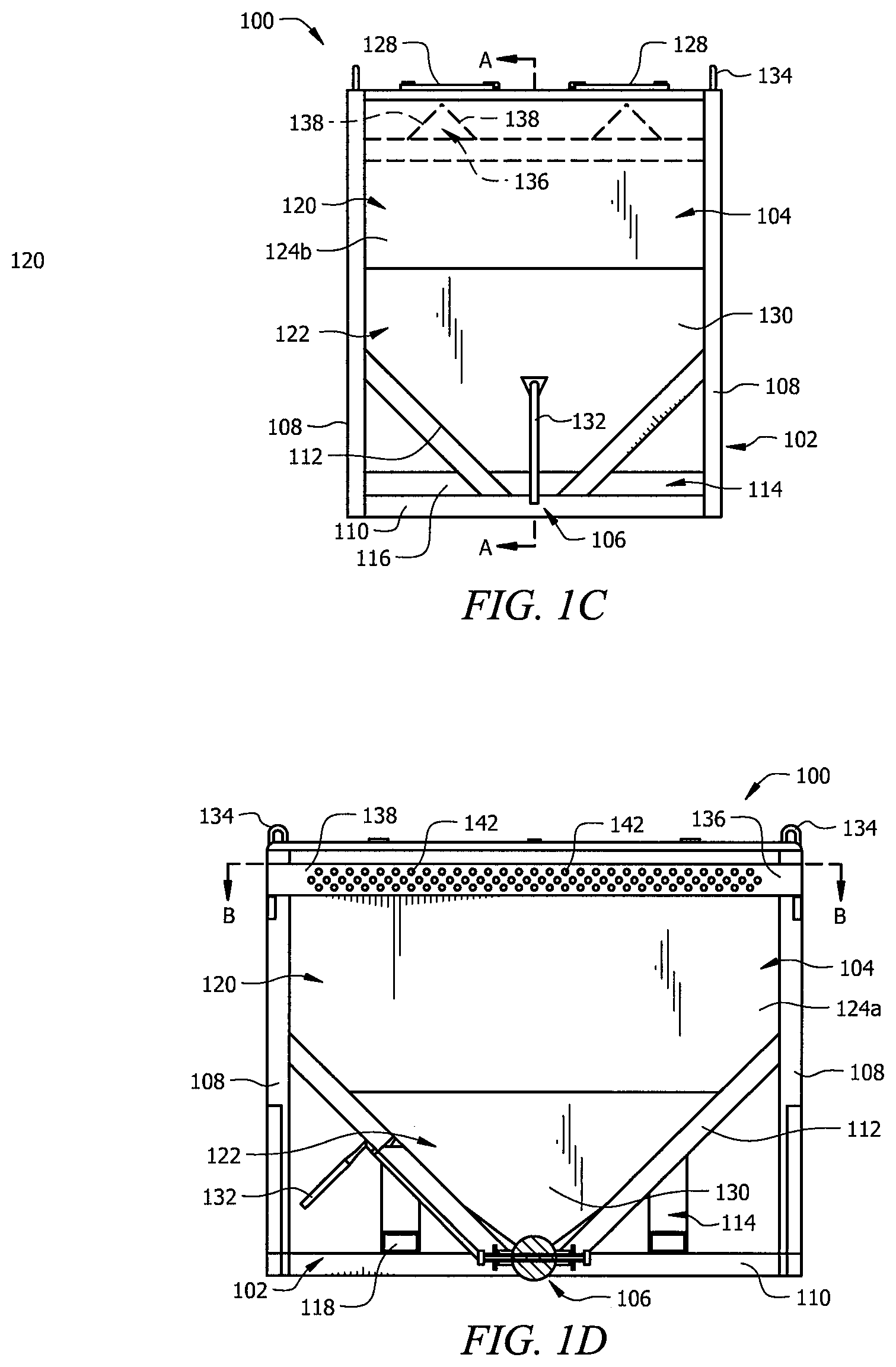
FIG. 1C is a side view of the bulk material storage unit of FIG. 1A;
FIG. 1D is a cross-section view of the bulk material storage unit of FIG. 1C along line A-A;
FIG. 1E is a top view of the bulk material storage unit of FIG. 1A;
FIG. 1F is a cross section view of the bulk material storage unit of FIG. 1D along line B-B;
FIGS. 2A and 2B illustrate exemplary angles of repose for certain deposited bulk material and corresponding volumes;
FIG. 3A is a perspective view of an exemplary embodiment of a diverter component of a bulk material storage according to certain aspects of the present invention.
FIG. 3B is an end view of the diverter component of FIG. 3A;
FIG. 4 is a perspective view of an exemplary embodiment to unload the bulk storage units shown in FIG. 1A from a flatbed according to certain aspects of the present invention;
FIG. 5 is a perspective view of the bulk storage units shown in FIG. 1A transported on a flatbed rail car and being loaded with bulk material according to certain aspects of the present invention;
FIG. 6 is a perspective view of exemplary bulk storage units of the present invention transported on a flatbed rail car;
FIG. 7 is a perspective view of the bulk storage units of FIG. 1A transported on a flatbed trailer;
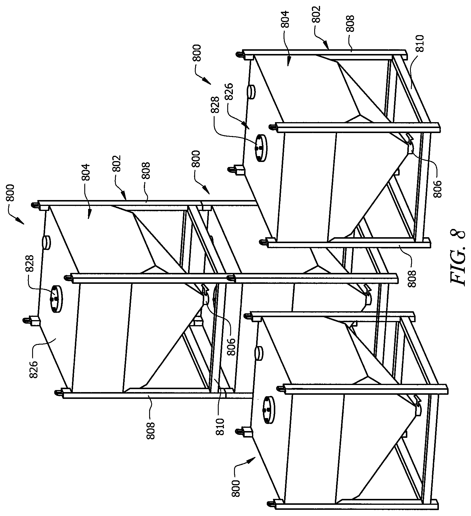
FIG. 8 is a perspective view of a second embodiment of a material storage unit according to certain aspects of the present invention;
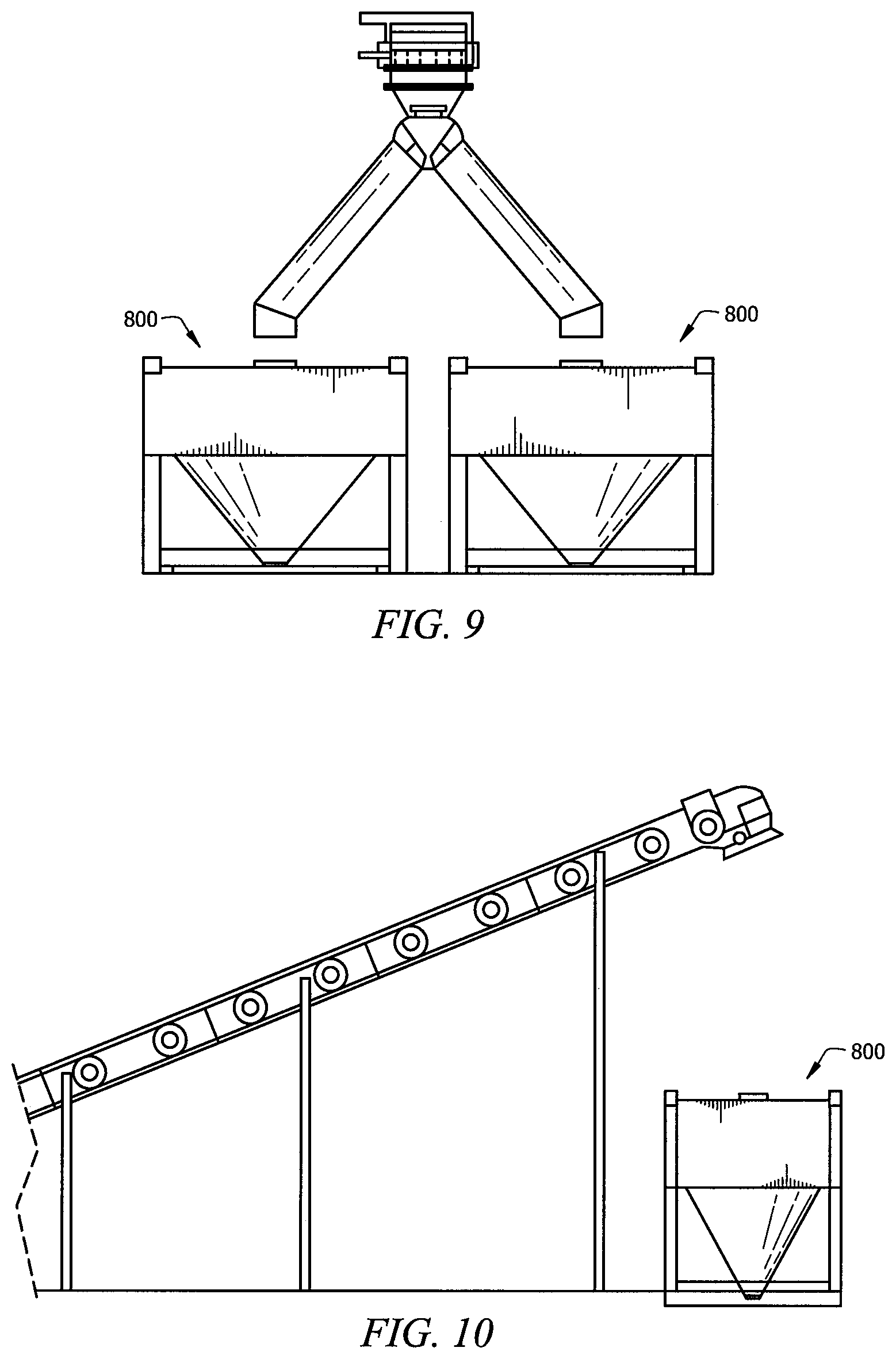
FIG. 9 is a side view of an exemplary embodiment to load the bulk material storage unit of FIG. 8; and
FIG. 10 is a side view of another exemplary embodiment to load the bulk material storage unit of FIG. 8.
It should be understood that the drawings are not necessarily to scale and that the disclosed embodiments are sometimes illustrated diagrammatically and in partial views. In certain instances, details which are not necessary for an understanding of the disclosed methods and apparatuses or which render other details difficult to perceive may have been omitted. Also, for simplification purposes, there may be only one exemplary instance, rather than all, is labeled. It should be understood, of course, that this disclosure is not limited to the particular embodiments illustrated herein.
DETAILED DESCRIPTION OF THE INVENTION
While embodiments of the present invention have a broad range of applications, they are particularly applicable for transportation of bulk materials using the railway or roadway systems. In railway transportation, the bulk material is typically loaded from silos at the source location into rail hopper cars for transport to the destination for use by the end users. If needs for the material is not immediate at the destination and storage is not available at that moment, these hopper cars usually end up sitting on the railway serving as temporary storage while taking up room on the rails that can lead to scheduling delays, thereby triggering a negative domino effect on the logistics. In roadway transportation, the bulk material is loaded from silos at the source location into truck trailers designed to hold bulk materials for transportation. Similar to railway transportation, if storage at the destination is lacking, the trucks need to remain there to serve as storage until the materials can be unloaded, thereby tying up resources in the logistical system.
Embodiments of the present invention provide bulk material storage units that can be placed on flatbed rail cars or flatbed trailers for transportation. The bulk material storage units of the present invention provide efficient storage of bulk material during transportations and upon arrival at the final destination.
Referring to FIGS. 1A-1F, one embodiment of the bulk material storage unit of the present invention is shown, storage component 100, which comprises frame component 102, storage component 104, and dispenser component 106. Frame component 102 provides support to storage component 104, which is attached to frame component 102. As shown in FIGS. 1A, 1C, 1D, and 1E, frame component 102 comprises vertical support members 108 preferably attached to the corners of storage component 104. In certain embodiments, frame component 102 also includes horizontal support members 110 extending between vertical support members 108. In the preferred embodiment, horizontal support members 110 are attached to vertical support members 108 near the end of vertical support members 108 toward the bottom of bulk material storage unit 100. In other embodiments, however, horizontal support members 110 can be placed at a higher position toward the top of bulk material storage unit 100 as appropriate. If additional support is needed or desired, frame component 102 can also include angled support members 112 extending between vertical support members 108 and horizontal support members 110. The angle of angled support members 112 can be varied as desired or required.
In the preferred embodiment, bulk material storage unit 100 further comprises transfer component 114 attached to frame component 102 that allow bulk material storage unit 100 to be placed onto or unloaded from the transport equipment, e.g. flatbed, and placed at a convenient location to provide temporary and portable storage of the bulk material. In one embodiment, transfer component 114 allows bulk material storage unit 100 to be moved by a forklift, such as forklift 402 as shown in FIG. 4. As shown in FIGS. 1A-1D, transfer component 114 comprises bars 116 extending across opposite horizontal support members 110 and spaced apart the appropriate distance to accommodate the forklift forks from one another. Referring to FIGS. 1A-1B and 1D, bars 116 also include openings 118 to allow insertion of the forklift forks. Alternatively or in addition to transfer component 114, bulk material storage unit 100 can further include another transfer component, such as lift ring 134, attached to the top of vertical support members 108. Lift ring 134 preferably comprises standard commercially available products that can be bolted in or welded in place. The capacity for lift ring 134 preferably meet the applicable ASME and OSHA standards.
Referring to FIGS. 1A-1D, storage component 104 comprises rectangular portion 120 and tapered portion 122. Rectangular portion 120 comprises four side walls 124a and 124b and top surface 126. Side walls 124a extend between two vertical support members 108 along the length of bulk material storage unit 100. Side walls 124b extend between two vertical support members 108 along the width of bulk material storage unit 100. As shown, the height of side walls 124a is longer than the height of side walls 124b. In embodiments where angled support members 112 are used, the corners of side walls 124a can be removed to accommodate certain angled support members 112, as swoon in FIGS. 1A-1B and 1D. Other embodiments can have different arrangements of side walls 124a and 124b.
Top surface 126 has openings (not shown) that allow the bulk material to be loaded into storage component 104 from above, such as shown in FIG. 5. Referring to FIGS. 1A and 1C, top surface 126 comprises lid members 128 to regulate access to storage component 104 through these openings. Referring to FIG. 1A, lid members 128 lay on top surface 126 and is attached to top surface 126 via hinges 140. In this configuration, lid members 128 open away from top surface 126. However, in other embodiments, lid members 128 can have other known arrangements, such as opening into top surface 126. Referring to FIGS. 1A and 1E, lid members 128 have dimensions that are slightly larger than the corresponding openings of top surface 126 so they can sufficiently cover the openings and protect the bulk material within when closed. In the preferred embodiment, the openings of top surface 126 and corresponding lid members 128 have a length that extend substantially along the length of top surface 126. The openings of top surface 126 and corresponding lid members 128 have a width that is sufficient to allow bulk material to be efficiently loaded into storage component 104. Thus, in certain embodiments, the width can vary depending on the particular bulk material and/or equipment, but it is preferable that the width is designed to be compatible with as many equipment and/or bulk material as possible. The dimensions of lid members 128 can vary. For example, lid member 128 can have a width of about 12 inches, about 18 inches, about 24 inches, about 36 inches, or about 48 inches. For applications involving fine particles such as sand, the preferred width is about 36 inches. If two lid members 128 are used, both can have the same or different width as desired. In one embodiment, the width of lid member 128 is at least dependent on the size of the down spout used to fill bulk material container unit 100. In the preferred embodiment, the length of lid member 128 is about 10 feet. In one embodiment, lid member 128 can be made out of any suitable light weight and durable material such as formed plastic, or fiberglass. In an embodiment for use with finer particles such as sand, the preferred material for lid member 128 is steel or aluminum.
Referring to FIGS. 1A-1D, tapered portion 122 includes four tapered walls 130 extending from each side wall 124 in a narrowing manner toward the bottom of bulk material storage unit 100. To maximize the volume of storage component 104, tapered portion 122 preferably ends near the bottom of bulk material storage unit 100. In the preferred embodiment, the angle at which walls 130 taper is about 45 degrees; however, tapered walls 130 can have any other angles, such as about 60 degrees, about 55 degrees, about 50 degrees, about 40 degrees, about 35 degrees, about 30 degrees, or about 25 degrees. An angle of about 45 degrees is a minimum angle at which the full effect of gravity acts on the particulate material inside storage component 104. While angles less than about 45 degrees gradually reduce the vertical force of gravity as the angle approaches 0 degrees, certain embodiments can employ such angles to sacrifice the gravity effect for additional volume where rapid dispensing of the bulk material may not be critical. Likewise, angles greater than about 45 degrees may be beneficial in certain applications.
Referring to FIGS. 1A-1F, tapered portion 122 ends with an opening (not shown) near the bottom bulk material storage unit 100 to allow unloading of the bulk material from storage component 104. Dispensing component 106 is attached to the end of tapered portion 122 to regulate the flow of the bulk material from storage component 104. In the preferred embodiment, dispensing component 106 retains the bulk material in storage component 104 and prevent leakage of the bulk material in the closed position. Referring to FIGS. 1A-1E, dispensing component 106 preferably also allows for adjustment of the rate of flow of the bulk material within the range from the closed position to fully open using actuator member 132. In one embodiment, dispensing component 106 comprises a valve, preferably a butterfly valve according to ASME standards.
Referring to FIGS. 1B-1F, in the preferred embodiment, to maximize the volume of bulk or particulate material that can be loaded into storage component 104, bulk material storage unit 100 further comprises diverter components 136 positioned below lid members 128. Diverter components 136 divert the bulk material pouring in from the top toward side walls 124 to minimize the angle of repose or the conical pile that typically forms when bulk or particulate material is poured through openings of top surface 126. FIGS. 2A and 2B demonstrate the angle of repose of bulk material 202 when poured through top surface 126 having one opening/one lid member 128 or two openings/two lid members 128, respectively, into storage component without any diverter component 136 installed. As shown in FIG. 2B, using top surface 126 with two openings can increase the volume of material that can be poured into storage component 104 as compared to only using one opening as shown in FIG. 2A. The two openings allow bulk material to be introduced to the sides of storage component 104, taking advantage of space near the top of storage component 104 that would be unavailable if only one opening was used. There are many factors that affect the angle of repose, or the internal angle between the surface of the pile and the horizontal surface, such as density, surface area and shapes of the particles, and the coefficient of friction of the material. Material with a low angle of repose forms flatter piles than material with a high angle of repose. As such, the decision to employ one or two openings, as well as corresponding diverter components 136, may be more critical in maximizing the volume of bulk materials with higher angle of repose that can be loaded as compared to bulk materials with lower angle of repose.
Referring to FIGS. 1B-1F and 3A-3B, each diverter component 136 preferably includes two ends attached to the inner surface of side walls 124b. A body extend between the two attached ends. The length of diverter component 136 preferably generally match the length of the respective opening of top surface 126 covered by lid member 128. The width of diverter component 136 (the maximum distance across diverter component 136) can be larger or smaller than the width of the respective opening of top surface 126. In one embodiment, the width of diverter component 136 is between about 12 inches and 48 inches, and more particularly, about 12 inches, about 18 inches, about 24 inches, about 36 inches, or about 48. In an exemplary embodiment, when used with down spouts having a width of about 24 inches, divert component 136 preferably has a width of about 24 inches, and for down spouts of about 36 inches, the width of diverter component 136 is about 36 inches.
In another embodiment, the body of diverter component 136 has two surfaces 138 angled away from each other that reduce the conical piling below the loading point of the bulk material. The incoming particulates hit angled surfaces 138 and get deflected toward the sides of storage component 104. Thus, the incoming bulk material fills up storage component 104 more evenly, thereby making more volume near the top of storage component 104 available for use as storage. In addition, diverter component 136 preferably comprises a plurality of apertures 142 to allow bulk material particulates to pass through. Referring to FIGS. 3A and 3B, diverter component 136 has three rows of apertures 142, and surfaces 138 are at an angle of about 30 degrees from the horizontal, as indicated by line 302. This can vary with different industries and particulate materials, ranging from about 27 degrees to about 89 degrees. For fine particles like sand and other particles with properties similar to sand, the preferred angle is about 30 degrees. In one embodiment, particularly for sand, the surface area provided by apertures 142 is about half of the total surface area of surfaces 138. As shown, apertures 142 has a diameter of about 1.5 inches, which is particularly suitable to sand and other similar fine particles. The diameter and surface area of apertures 142 can vary with other industries and materials, where at least the density and permeability of the particulate material being loaded. It is understood that the location, size, and/or shape of apertures 142 can vary to optimally reduce of the angle of repose of the material being loaded, thereby maximizing the use of space within storage component 104. In particular, each of the position, size, and shape of apertures 142 can each be varied. For instance, an exemplary diverter component can have apertures 142 of various sizes and/or shapes that are positioned in uniform or nonuniform arrangement.
Further, it should be understood that the illustrated diverter component 136 with angled surfaces 138 is merely illustrative and not intended to limit the present invention. Diverter component 136 deflects particulates toward the walls of storage component 104, thereby disrupting the flow of particulates into storage component 104 that can form a conical pile if left undisturbed. The deflection of particulates can be implemented in other forms within the skill of one of ordinary skill in the art. For example, instead of or in addition to apertures 142, angled surfaces 138 can comprise a plurality of fingers where certain particulates would be deflected when they hit the surface of these fingers while others fall through the gaps between the fingers. Another example includes a cylinder with a plurality of protrusions that is configured to spin as particulates are flowing in and hitting the surfaces of the cylinder.
In the preferred embodiment, for every opening of top surface 126 and lid member 128, there is provided a divert component 136 placed below the respective opening of the top surface 126 to direct incoming bulk material to the side and minimize the angle of repose. Also, in other embodiments, such as that shown in FIG. 4, top surface 126 can comprise one opening (not shown) and one lid member 128. Storage component 104 of bulk material storage unit of FIG. 4 preferably includes one corresponding diverter component 136 placed below the single lid member 128.
In the preferred embodiment, bulk material storage unit 100 is sized to be compatible with equipment at the source location, the transport equipment, and equipment at the destination. Bulk material storage unit 100 is preferably adapted to fit flatbed rail cars for rail transportation or flatbed trailers for roadway transportation. The preferred bulk material storage unit has dimensions that are compatible with both railway and roadway transportation equipment for versatility. Based on dimensions of flatbeds currently used for both railway and roadway transport and roadway regulations governing the height of trailers, the preferred bulk material storage unit 100 has a length of less than about 12 feet, a width of less than about 8 feet 6 inches, and a height of less than about 10 feet. In particular, bulk material storage unit 100 more preferably has a length of about 12 feet, a width of about 8 feet 4 inches, a height of about 9 feet 9 1/16 inches, not including any lift ring 134. In one embodiment, diverter component 136 is attached to the interior of side walls 124b through welding or it can be bolted to side walls 124b. In certain embodiments, angular supports can be used to reinforce the anchoring at the location of attachment. Diverter component 136 is preferably attached to side walls 124b so that the distance between the peak angle of diverter component 136 and top surface 126 of about 1 to 18 inches. The specific distance can vary depending on the density and angle of deflection of the product being loaded into bulk material storage unit 100. For applications involving fine particles such as sand, the preferred distance from top surface 126 is about 3 inches determined based at least on the density of sand. Sand products can vary from about 8-16 mesh to about 100 mesh in size. Storage component 104 preferably is configured with dimensions to provide it with the capacity to hold up to 675 cubic feet of volume. Components of bulk material storage unit 100 can be made of durable materials such as steel, aluminum, fiberglass, plastic, or a combination thereof.
Referring to FIGS. 4-7, four bulk material storage units 100 can fit on a flatbed that is about 48 feet long, whether for a rail car, e.g., rail car 404 as shown in FIGS. 4-6, or a trailer, e.g., trailer 704, as shown in FIG. 7. Referring to FIG. 4, bulk material storage units 100 can be transferred to and from flatbed 406, whether transported by rail or road, using forklift 402. Alternatively or in addition, bulk material storage units 100 can be transferred to and from flatbed 406 using a crane or similar lifting device through transfer component 114. While four bulk material storage units 100 can be placed on a flatbed of about 48 feet long, certain transportation regulations governing weight, particularly for roadways, may restrict the actual number of full bulk material storage units 100 that can be hauled by a particular at any one time. If bulk material storage units 100 are empty or not fully filled. This can expedite the logistics process and cut transport costs by enabling multiple empty bulk material storage units 100 to be returned by one truck for every one full bulk material storage unit 100 delivered, where conventional trailers cannot provide this increased capability.
Referring to FIG. 8, according to another aspect, there is provided a second embodiment of the bulk material storage unit of the present invention, bulk material storage unit 800, which is similar to bulk material storage unit 100 of FIGS. 1A-1F. Certain descriptions of bulk material storage unit 100 are also applicable to bulk material storage unit 100, such as dimensions, composition materials, and manners of transfer or transportation. Bulk material storage unit 800 also comprises frame component 802, storage component 804, and dispenser component 806. Frame component 802, however, does not include any angled support members. Further, the arrangements of the components of bulk material storage units 800 are modified to allow bulk material storage to stack on top of one another. As shown, storage component 804 and horizontal support members 810 are respectively attached to frame component 802 such that a portion of the top and bottom of each vertical support member 808 are available so the top of vertical support members 808 of one storage unit 800 can engage and attach to the bottom of vertical support members 808 of another storage unit 800. As shown, bulk material storage unit 800 also includes lid member 828 placed generally in the center of top surface 826 that is round instead of rectangular like lid members 128 of bulk material storage unit 100. The shape and location of lid member 828 can allow for transferring of bulk material from a higher stacked storage unit 800 to a lower stacked storage unit 800. It is understood that any one or more of these modifications can be made to bulk material storage unit 100. Other known modifications can also be made to bulk material storage unit 100 to make it stackable.
According to another aspect of the present invention, there is provided a method of transporting bulk material using embodiments of the bulk material storage unit disclosed herein. The transport of bulk material begins with loading of bulk material into the bulk material storage units at the origin, whether it is the source location where the bulk material is collected, an off-site storage location, an intermediate transport point, etc. FIG. 5 shows one way of loading of bulk material storage units 100 with two lid members 128 hauled by rail car 404. Railway 502 runs through silo 504 allowing successive bulk material storage units 100 to be pulled to the proper position underneath dispenser 506 of silo 504 to receive the bulk material. FIGS. 9 and 10 show exemplary ways of filling bulk material storage unit 800.
Once the bulk material storage units are filled, they are transported to the destination via the particular transportation mode, e.g., rail cars or trucks. The destination can be the final delivery point for the end-user, an intermediate transport point, etc. If storage of the bulk material, whether permanent or temporary, is needed at the destination, the bulk material storage units can be unloaded from the rail cars or trucks and transferred to the desired location. Referring to FIG. 4, unloading of bulk material storage units 100 can be achieved with forklift 402 Embodiments of the present invention allow for storage to be stored immediately without requiring existing storage infrastructures at the destination, thereby freeing the transportation equipment to be utilized elsewhere, preventing obstruction of the logistics flow, and reducing costs associated with constructing storage structures. Embodiments of the present invention also eliminate any costs or material loss associated with the transfer of bulk material from conventional shipping containers to a storage container by providing bulk material storage units that can serve as both. If the stored bulk material needs to be moved to another location or transported again via rail way or road way, the bulk material storage units can be moved via the transfer components as described above. Embodiments of the present invention also allow for straightforward transfer of only a portion of the stored bulk material by transferring only the desired number of bulk material storage units. Further, the portability of embodiments of the present invention provides storage flexibilities to adapt to the changing market where stored bulk material and/or storage space can be moved cost effectively to other regions.
As mentioned, embodiments of the present invention are applicable to meet needs of industries that involve storage and transport of particulate materials, such as sand, grains, ores, gravel, stone, etc. Certain embodiments, however, are particularly applicable for storing and transporting sand or similar fine particles. A specific industry that requires a large amount of sand to be delivered from the mines is the oil and gas industry, which uses the sand as proppants in hydraulic fracturing at well sites. While the following descriptions specifically mention sand, it is understood they can be similarly applicable to other industries and particulate materials. Current rail transportation of sand uses rail hopper cars which are not designed to retain fine particles like sand, which often lead to product loss during transportation. This loss is typically referred to as variance. Variance in the oil and gas industry today ranges approximately 3% to 10%. Embodiments of the present invention can reduce or eliminate this variance because they are configured to prevent leakage.
When sand is delivered to the well site, it is typically injected into the well using pneumatic trailers. Embodiments of the present invention can reduce the number of pneumatic trailers used by allowing the sand to be stored closer to the well, thereby making the sand more accessible. Embodiments of the present invention can also facilitate in eliminating use of the pneumatic trailers through the use of an alternative sand injection that can take advantage of the cone shape of the vessel. It is designed to use gravity as one energy source to introduce the sand into the well.
Sand has different angles of repose depending on its properties. Dry sand has an angle of repose of about 34 degrees, moist sand has an angle of repose of about 15 degrees and 30 degrees, and wet sand has an angle of repose of about 45 degrees. As discussed above, more volume of moist sand can be filled as compared to dry and wet sand because moist sand has the lowest angle of repose. Specifically, for a bulk material storage unit with dimensions of about 12 feet in length, about 8 feet 4 inches in width, and about 9 feet and 9 1/16 inches in height, the volume for a 45 degrees angle of repose for a single opening surface, as shown in FIG. 2A, is about 360 cubic feet, and the volume for a 34 degrees angle of repose is 425 cubic feet. For a two-opening surface, as shown in FIG. 2B, the volume for a 45 degree angle of repose is 460 cubic feet compared to the volume for a 34 degree angle of repose is 493 cubic feet.
As described, the volume of sand that can be loaded is increased by using two openings. This volume can further be increased by using diverter components 136, as described above. In one embodiment, under normal conditions, an increase of about 2,000 to 6,000 lbs. can be achieved for sand products. Referring to FIGS. 3A and 3B, as described above, diverter component 136 has three rows of apertures 142, and surfaces 138 are at an angle of about 30 degrees from the horizontal, as indicated by line 302. The surface area provided by apertures 142 is about half of the total surface area of surfaces 138. As shown, apertures 142 has a diameter of about 1.5 inches, which is particularly suitable to sand and other similar fine particles. For other industries and particulate materials, diverter components 136 are reconfigured to suit the conditions of such industries and materials, including but not limited to modifications to the dimensions, angle of surfaces 138, surface area of apertures 142, number and arrangement of apertures 142, and diameter of apertures 142.
Although the present disclosure and its advantages have been described in detail, it should be understood that various changes, substitutions and alterations can be made herein without departing from the spirit and scope of the disclosure as defined by the appended claims. Moreover, the scope of the present application is not intended to be limited to the particular embodiments of the process, machine, manufacture, composition of matter, means, methods and steps described in the specification. As one of ordinary skill in the art will readily appreciate from the disclosure of the present disclosure, processes, machines, manufacture, compositions of matter, means, methods, or steps, presently existing or later to be developed that perform substantially the same function or achieve substantially the same result as the corresponding embodiments described herein may be utilized according to the present disclosure. Accordingly, the appended claims are intended to include within their scope such processes, machines, manufacture, compositions of matter, means, methods, or steps.
* * * * *
References
D00000
D00001
D00002
D00003
D00004
D00005
D00006
D00007
D00008
D00009
D00010
D00011
XML
uspto.report is an independent third-party trademark research tool that is not affiliated, endorsed, or sponsored by the United States Patent and Trademark Office (USPTO) or any other governmental organization. The information provided by uspto.report is based on publicly available data at the time of writing and is intended for informational purposes only.
While we strive to provide accurate and up-to-date information, we do not guarantee the accuracy, completeness, reliability, or suitability of the information displayed on this site. The use of this site is at your own risk. Any reliance you place on such information is therefore strictly at your own risk.
All official trademark data, including owner information, should be verified by visiting the official USPTO website at www.uspto.gov. This site is not intended to replace professional legal advice and should not be used as a substitute for consulting with a legal professional who is knowledgeable about trademark law.