Sequentially deployed transcatheter mitral valve prosthesis
Lane , et al. Ja
U.S. patent number 10,537,422 [Application Number 15/628,924] was granted by the patent office on 2020-01-21 for sequentially deployed transcatheter mitral valve prosthesis. This patent grant is currently assigned to Neovasc Tiara Inc.. The grantee listed for this patent is Neovasc Tiara Inc.. Invention is credited to Randy Matthew Lane, Alexei J. Marko, Krista L. Neale, Colin A. Nyuli.


View All Diagrams
| United States Patent | 10,537,422 |
| Lane , et al. | January 21, 2020 |
Sequentially deployed transcatheter mitral valve prosthesis
Abstract
A sequentially deployed prosthetic cardiac valve includes a self-expanding frame having an atrial skirt, a ventricular skirt, and an annular region disposed therebetween. A first anterior tab is disposed on an anterior portion of the frame. A posterior tab is on a posterior portion of the self-expanding frame. The frame may be designed so that any portion may expand sequentially in any desired order. For example, a portion of the first anterior tab and a portion of the posterior tab may partially self-expand first. Next, the first anterior tab may fully self-expand before the posterior tab fully self-expands. The posterior tab may fully self-expand next followed by the ventricular skirt, or the ventricular skirt may self-expand next followed by full expansion of the posterior tab.
| Inventors: | Lane; Randy Matthew (Langley, CA), Nyuli; Colin A. (Vancouver, CA), Marko; Alexei J. (Vancouver, CA), Neale; Krista L. (Vancouver, CA) | ||||||||||
|---|---|---|---|---|---|---|---|---|---|---|---|
| Applicant: |
|
||||||||||
| Assignee: | Neovasc Tiara Inc. (Richmond,
British Columbia, CA) |
||||||||||
| Family ID: | 48468940 | ||||||||||
| Appl. No.: | 15/628,924 | ||||||||||
| Filed: | June 21, 2017 |
Prior Publication Data
| Document Identifier | Publication Date | |
|---|---|---|
| US 20170281336 A1 | Oct 5, 2017 | |
Related U.S. Patent Documents
| Application Number | Filing Date | Patent Number | Issue Date | ||
|---|---|---|---|---|---|
| 15046371 | Feb 17, 2016 | 9713529 | |||
| 13679920 | Nov 16, 2012 | 9308087 | |||
| 61563156 | Nov 23, 2011 | ||||
| Current U.S. Class: | 1/1 |
| Current CPC Class: | A61F 2/2403 (20130101); A61F 2/2412 (20130101); A61F 2/2436 (20130101); A61F 2/243 (20130101); A61F 2/2409 (20130101); A61F 2/2427 (20130101); A61F 2/2418 (20130101); A61F 2230/0054 (20130101); A61F 2220/0058 (20130101); A61F 2220/0016 (20130101); A61F 2230/005 (20130101); A61F 2220/005 (20130101); A61F 2220/0075 (20130101) |
| Current International Class: | A61F 2/24 (20060101) |
References Cited [Referenced By]
U.S. Patent Documents
| 3548417 | December 1970 | Kischer |
| 3657744 | April 1972 | Ersek |
| 3671979 | June 1972 | Moulopoulos |
| 3739402 | June 1973 | Kahn et al. |
| 4056854 | November 1977 | Boretos et al. |
| 4079468 | March 1978 | Liotta et al. |
| 4204283 | May 1980 | Bellhouse et al. |
| 4222126 | September 1980 | Boretos et al. |
| 4265694 | May 1981 | Boretos et al. |
| 4339831 | July 1982 | Johnson |
| 4340977 | July 1982 | Brownlee et al. |
| 4470157 | September 1984 | Love |
| 4477930 | October 1984 | Totten et al. |
| 4490859 | January 1985 | Black et al. |
| 4553545 | November 1985 | Maass et al. |
| 4655771 | April 1987 | Wallsten et al. |
| 4733665 | March 1988 | Palmaz et al. |
| 4776337 | October 1988 | Palmaz et al. |
| 4777951 | October 1988 | Cribier et al. |
| 4865600 | September 1989 | Carpentier et al. |
| 4950227 | August 1990 | Savin et al. |
| 4994077 | February 1991 | Dobben |
| 5067957 | November 1991 | Jervis |
| 5197978 | March 1993 | Hess et al. |
| 5326371 | July 1994 | Love et al. |
| 5332402 | July 1994 | Teitelbaum |
| 5344427 | September 1994 | Cottenceau et al. |
| 5370685 | December 1994 | Stevens |
| 5397355 | March 1995 | Marin et al. |
| 5411552 | May 1995 | Andersen et al. |
| 5415667 | May 1995 | Frater |
| 5439446 | August 1995 | Barry |
| 5474563 | December 1995 | Myler et al. |
| 5509930 | April 1996 | Love |
| 5545214 | August 1996 | Stevens |
| 5554185 | September 1996 | Block et al. |
| 5575818 | November 1996 | Pinchuk |
| 5607444 | March 1997 | Lam |
| 5607469 | March 1997 | Frey |
| 5669919 | September 1997 | Sanders et al. |
| 5697382 | December 1997 | Love et al. |
| D390957 | February 1998 | Fontaine |
| 5713952 | February 1998 | Vanney et al. |
| 5725519 | March 1998 | Penner et al. |
| 5769812 | June 1998 | Stevens et al. |
| 5807398 | September 1998 | Shaknovich |
| 5810873 | September 1998 | Morales |
| 5840081 | November 1998 | Andersen et al. |
| 5855601 | January 1999 | Bessler et al. |
| 5868777 | February 1999 | Lam |
| 5868782 | February 1999 | Frantzen |
| 5876437 | March 1999 | Vanney et al. |
| 5879381 | March 1999 | Moriuchi et al. |
| 5902334 | May 1999 | Dwyer et al. |
| 5928281 | July 1999 | Huynh et al. |
| 5935108 | August 1999 | Katoh et al. |
| 5954764 | September 1999 | Parodi |
| 5957949 | September 1999 | Leonhardt et al. |
| 5992000 | November 1999 | Humphrey et al. |
| 6004328 | December 1999 | Solar |
| 6015431 | January 2000 | Thornton et al. |
| 6042606 | March 2000 | Frantzen |
| 6053940 | April 2000 | Wijay |
| 6074417 | June 2000 | Peredo |
| 6086612 | July 2000 | Jansen |
| 6113612 | September 2000 | Swanson et al. |
| 6113631 | September 2000 | Jansen |
| 6132458 | October 2000 | Staehle et al. |
| 6152937 | November 2000 | Peterson et al. |
| 6159237 | December 2000 | Alt et al. |
| 6168614 | January 2001 | Andersen et al. |
| 6168616 | January 2001 | Brown, III |
| 6251093 | June 2001 | Valley et al. |
| 6280466 | August 2001 | Kugler et al. |
| 6306141 | October 2001 | Jervis |
| 6312465 | November 2001 | Griffin et al. |
| 6336938 | January 2002 | Kavteladze et al. |
| 6352543 | March 2002 | Cole |
| 6358277 | March 2002 | Duran |
| 6425916 | July 2002 | Garrison et al. |
| 6440164 | August 2002 | DiMatteo et al. |
| 6458153 | October 2002 | Bailey et al. |
| 6475237 | November 2002 | Drasler et al. |
| 6482228 | November 2002 | Norred |
| 6511491 | January 2003 | Grudem et al. |
| 6517573 | February 2003 | Pollock et al. |
| 6527800 | March 2003 | McGuckin, Jr. et al. |
| 6551303 | April 2003 | Van Tassel et al. |
| 6582462 | June 2003 | Andersen et al. |
| 6602281 | August 2003 | Klein |
| 6610088 | August 2003 | Gabbay |
| 6629534 | October 2003 | St. Goar et al. |
| 6641606 | November 2003 | Ouriel et al. |
| 6652578 | November 2003 | Bailey et al. |
| D484979 | January 2004 | Fontaine |
| 6676698 | January 2004 | McGuckin et al. |
| 6682537 | January 2004 | Ouriel et al. |
| 6695878 | February 2004 | McGuckin et al. |
| 6702843 | March 2004 | Brown et al. |
| 6712836 | March 2004 | Berg et al. |
| 6723123 | April 2004 | Kazatchkov et al. |
| 6730118 | May 2004 | Spenser et al. |
| 6733523 | May 2004 | Shaolian et al. |
| 6764505 | July 2004 | Hossainy et al. |
| 6767362 | July 2004 | Schreck |
| 6780200 | August 2004 | Jansen |
| 6790229 | September 2004 | Berreklouw |
| 6790230 | September 2004 | Beyersdorf et al. |
| 6814746 | November 2004 | Thompson et al. |
| 6858034 | February 2005 | Hijlkema et al. |
| 6875231 | April 2005 | Anduiza et al. |
| 6893460 | May 2005 | Spenser et al. |
| 6908477 | June 2005 | McGuckin et al. |
| 6908481 | June 2005 | Cribier |
| 6926732 | August 2005 | Derus et al. |
| 6929660 | August 2005 | Ainsworth et al. |
| 6936058 | August 2005 | Forde et al. |
| 6979350 | December 2005 | Moll et al. |
| 7014653 | March 2006 | Ouriel et al. |
| 7018401 | March 2006 | Hyodoh et al. |
| 7018406 | March 2006 | Seguin et al. |
| 7025780 | April 2006 | Gabbay |
| 7044962 | May 2006 | Elliot et al. |
| 7044966 | May 2006 | Svanidze et al. |
| 7087088 | August 2006 | Berg et al. |
| 7147660 | December 2006 | Chobotov et al. |
| 7147661 | December 2006 | Chobotov et al. |
| 7147663 | December 2006 | Berg et al. |
| 7153322 | December 2006 | Alt |
| 7186265 | March 2007 | Sharkawy et al. |
| 7198646 | April 2007 | Figulla et al. |
| 7201772 | April 2007 | Schwammenthal et al. |
| 7252682 | August 2007 | Seguin |
| D553747 | October 2007 | Fliedner |
| 7276078 | October 2007 | Spenser et al. |
| 7276084 | October 2007 | Yang et al. |
| 7329278 | February 2008 | Seguin et al. |
| 7338520 | March 2008 | Bailey et al. |
| 7381219 | June 2008 | Salahieh et al. |
| 7393360 | July 2008 | Spenser et al. |
| 7429269 | September 2008 | Schwammenthal et al. |
| 7435257 | October 2008 | Lashinski et al. |
| 7442204 | October 2008 | Schwammenthal et al. |
| 7445631 | November 2008 | Haug et al. |
| 7455689 | November 2008 | Johnson |
| 7462191 | December 2008 | Spenser et al. |
| 7510575 | March 2009 | Spenser et al. |
| 7524330 | April 2009 | Berreklouw |
| 7527646 | May 2009 | Rahdert et al. |
| 7585321 | September 2009 | Cribier |
| 7608114 | October 2009 | Levine et al. |
| 7615072 | November 2009 | Rust et al. |
| 7618446 | November 2009 | Andersen et al. |
| 7618447 | November 2009 | Case et al. |
| 7628805 | December 2009 | Spenser et al. |
| 7632298 | December 2009 | Hijlkema et al. |
| 7637945 | December 2009 | Solem et al. |
| 7637946 | December 2009 | Solem et al. |
| 7682390 | March 2010 | Seguin |
| 7708775 | May 2010 | Rowe et al. |
| 7712606 | May 2010 | Salahieh et al. |
| 7748389 | July 2010 | Salahieh et al. |
| 7753949 | July 2010 | Lamphere et al. |
| D622387 | August 2010 | Igaki |
| D622388 | August 2010 | Igaki |
| 7771463 | August 2010 | Ton et al. |
| 7771472 | August 2010 | Hendricksen et al. |
| 7780725 | August 2010 | Haug et al. |
| 7785360 | August 2010 | Freitag |
| 7799072 | September 2010 | Greenberg |
| 7803185 | September 2010 | Gabbay |
| 7806917 | October 2010 | Xiao |
| 7806919 | October 2010 | Bloom et al. |
| 7815589 | October 2010 | Meade et al. |
| 7815673 | October 2010 | Bloom et al. |
| 7824443 | November 2010 | Salahieh et al. |
| 7837727 | November 2010 | Goetz et al. |
| 7846203 | December 2010 | Cribier |
| 7871435 | January 2011 | Carpentier et al. |
| 7892281 | February 2011 | Seguin et al. |
| D635261 | March 2011 | Rossi |
| D635262 | March 2011 | Rossi |
| 7896915 | March 2011 | Guyenot et al. |
| 7914569 | March 2011 | Nguyen et al. |
| 7914575 | March 2011 | Guyenot et al. |
| 7919112 | April 2011 | Pathak et al. |
| 7947075 | May 2011 | Goetz et al. |
| 7959672 | June 2011 | Salahieh et al. |
| 7967853 | June 2011 | Eidenschink et al. |
| 7972377 | July 2011 | Lane |
| 7972378 | July 2011 | Tabor et al. |
| 7981151 | July 2011 | Rowe |
| 7993392 | August 2011 | Righini et al. |
| 7993394 | August 2011 | Hariton et al. |
| 7993395 | August 2011 | Vanermen et al. |
| 7998196 | August 2011 | Mathison |
| 8009887 | August 2011 | Ionasec et al. |
| 8016870 | September 2011 | Chew et al. |
| 8016877 | September 2011 | Seguin et al. |
| 8029564 | October 2011 | Johnson et al. |
| 8048153 | November 2011 | Salahieh et al. |
| 8052747 | November 2011 | Melnikov et al. |
| 8052750 | November 2011 | Tuval et al. |
| 8057538 | November 2011 | Bergin et al. |
| 8057539 | November 2011 | Ghione et al. |
| 8057540 | November 2011 | Letac et al. |
| 8062350 | November 2011 | Gale et al. |
| 8062359 | November 2011 | Marquez et al. |
| 8066763 | November 2011 | Alt |
| 8070799 | December 2011 | Righini et al. |
| 8070800 | December 2011 | Lock et al. |
| 8070801 | December 2011 | Cohn |
| 8070802 | December 2011 | Lamphere et al. |
| 8075611 | December 2011 | Millwee et al. |
| 8075615 | December 2011 | Eberhardt et al. |
| 8078279 | December 2011 | Dennis et al. |
| 8080054 | December 2011 | Rowe |
| 8083793 | December 2011 | Lane et al. |
| 8088158 | January 2012 | Brodeur |
| 8088404 | January 2012 | Udipi et al. |
| 8092520 | January 2012 | Quadri |
| 8100964 | January 2012 | Spence |
| 8105375 | January 2012 | Navia et al. |
| 8105377 | January 2012 | Liddicoat |
| 8109995 | February 2012 | Paniagua et al. |
| 8109996 | February 2012 | Stacchino et al. |
| 8114154 | February 2012 | Righini et al. |
| 8118866 | February 2012 | Herrmann et al. |
| 8119704 | February 2012 | Wang et al. |
| 8123801 | February 2012 | Milo |
| 8128681 | March 2012 | Shoemaker et al. |
| 8128688 | March 2012 | Ding et al. |
| 8136218 | March 2012 | Millwee et al. |
| 8137398 | March 2012 | Tuval et al. |
| 8137687 | March 2012 | Chen et al. |
| 8142492 | March 2012 | Forster et al. |
| 8142494 | March 2012 | Rahdert et al. |
| 8147504 | April 2012 | Ino et al. |
| 8155754 | April 2012 | Nygren et al. |
| 8157852 | April 2012 | Bloom et al. |
| 8157853 | April 2012 | Laske et al. |
| 8158187 | April 2012 | Chen et al. |
| 8163014 | April 2012 | Lane et al. |
| 8167926 | May 2012 | Hartley et al. |
| 8167932 | May 2012 | Bourang et al. |
| 8167934 | May 2012 | Styrc et al. |
| 8168275 | May 2012 | Lee et al. |
| 8170645 | May 2012 | Solar et al. |
| 8177799 | May 2012 | Orban, III |
| 8177836 | May 2012 | Lee et al. |
| 8180428 | May 2012 | Kaiser et al. |
| 8182528 | May 2012 | Salahieh et al. |
| 8182530 | May 2012 | Huber et al. |
| 8182829 | May 2012 | Kleiner et al. |
| 8187851 | May 2012 | Shah et al. |
| 8195293 | June 2012 | Limousin et al. |
| 8202529 | June 2012 | Hossainy et al. |
| 8211169 | July 2012 | Lane et al. |
| 8216261 | July 2012 | Solem et al. |
| 8216301 | July 2012 | Bonhoeffer et al. |
| 8219229 | July 2012 | Cao et al. |
| 8220121 | July 2012 | Hendriksen et al. |
| 8221482 | July 2012 | Cottone et al. |
| 8221493 | July 2012 | Bailey et al. |
| 8226710 | July 2012 | Nguyen et al. |
| 8231930 | July 2012 | Castro et al. |
| D665079 | August 2012 | Zago |
| D665080 | August 2012 | Zago |
| 8236045 | August 2012 | Benichou et al. |
| 8236241 | August 2012 | Carpentier et al. |
| 8241274 | August 2012 | Keogh et al. |
| 8246675 | August 2012 | Zegdi |
| 8246677 | August 2012 | Ryan |
| 8246678 | August 2012 | Haug et al. |
| 8252051 | August 2012 | Chau et al. |
| 8252052 | August 2012 | Salahieh et al. |
| 8257724 | September 2012 | Cromack et al. |
| 8257725 | September 2012 | Cromack et al. |
| 8262724 | September 2012 | Seguin et al. |
| 8273118 | September 2012 | Bergin |
| 8273120 | September 2012 | Dolan |
| 8276533 | October 2012 | Chambers et al. |
| 8287584 | October 2012 | Salahieh et al. |
| 8287591 | October 2012 | Keidar et al. |
| 8303653 | November 2012 | Bonhoeffer et al. |
| 8308798 | November 2012 | Pintor et al. |
| 8313520 | November 2012 | Barbut et al. |
| 8313525 | November 2012 | Tuval et al. |
| 8317854 | November 2012 | Ryan et al. |
| 8323335 | December 2012 | Rowe et al. |
| 8323336 | December 2012 | Hill et al. |
| 8337541 | December 2012 | Quadri et al. |
| 8348995 | January 2013 | Tuval et al. |
| 8349001 | January 2013 | Mensah et al. |
| 8349003 | January 2013 | Shu et al. |
| 8353921 | January 2013 | Schaller et al. |
| 8353948 | January 2013 | Besselink et al. |
| 8353953 | January 2013 | Giannetti et al. |
| 8357387 | January 2013 | Dove et al. |
| 8361137 | January 2013 | Perouse |
| 8361537 | January 2013 | Shanley |
| 8366769 | February 2013 | Huynh et al. |
| 8377116 | February 2013 | Hsu et al. |
| 8377499 | February 2013 | Kleiner et al. |
| 8382816 | February 2013 | Pollock et al. |
| RE44075 | March 2013 | Williamson et al. |
| 8398707 | March 2013 | Bergin |
| 8398708 | March 2013 | Meiri et al. |
| 8403983 | March 2013 | Quadri et al. |
| 8408214 | April 2013 | Spenser |
| 8409274 | April 2013 | Li et al. |
| 8414635 | April 2013 | Hyodoh et al. |
| 8414643 | April 2013 | Tuval et al. |
| 8414644 | April 2013 | Quadri et al. |
| 8414645 | April 2013 | Dwork et al. |
| 8430902 | April 2013 | Bergheim |
| 8430927 | April 2013 | Bonhoeffer |
| 8444689 | May 2013 | Zhang |
| 8449466 | May 2013 | Duhay et al. |
| 8449599 | May 2013 | Chau et al. |
| 8449625 | May 2013 | Campbell et al. |
| 8454684 | June 2013 | Bergin et al. |
| 8454685 | June 2013 | Hariton et al. |
| 8460335 | June 2013 | Carpenter |
| 8460365 | June 2013 | Haverkost et al. |
| 8460366 | June 2013 | Rowe et al. |
| 8460370 | June 2013 | Zakay et al. |
| 8460373 | June 2013 | Fogarty et al. |
| 8470023 | June 2013 | Eidenschink et al. |
| 8470024 | June 2013 | Ghione et al. |
| 8475521 | July 2013 | Suri et al. |
| 8475522 | July 2013 | Jimenez et al. |
| 8475523 | July 2013 | Duffy |
| 8479380 | July 2013 | Malewicz et al. |
| 8480730 | July 2013 | Maurer et al. |
| 8480731 | July 2013 | Elizondo et al. |
| 8486137 | July 2013 | Suri et al. |
| 8491650 | July 2013 | Wiemeyer et al. |
| 8500688 | August 2013 | Engel et al. |
| 8500755 | August 2013 | Ino et al. |
| 8500798 | August 2013 | Rowe et al. |
| 8500801 | August 2013 | Eberhardt et al. |
| 8500802 | August 2013 | Lane et al. |
| 8506620 | August 2013 | Ryan |
| 8506625 | August 2013 | Johnson |
| 8511244 | August 2013 | Holecek et al. |
| 8512397 | August 2013 | Rolando et al. |
| 8512398 | August 2013 | Alkhatib |
| 8512399 | August 2013 | Lafontaine |
| 8512401 | August 2013 | Murray, III et al. |
| 8518106 | August 2013 | Duffy et al. |
| 8518108 | August 2013 | Huynh et al. |
| 8529621 | September 2013 | Alfieri et al. |
| 8535368 | September 2013 | Headley et al. |
| 8539662 | September 2013 | Stacchino et al. |
| 8545742 | October 2013 | Gada et al. |
| 8551162 | October 2013 | Fogarty et al. |
| 8562663 | October 2013 | Mearns et al. |
| 8562672 | October 2013 | Bonhoeffer et al. |
| 8562673 | October 2013 | Yeung et al. |
| 8565872 | October 2013 | Pederson |
| 8568472 | October 2013 | Marchand et al. |
| 8579964 | November 2013 | Lane et al. |
| 8579965 | November 2013 | Bonhoeffer et al. |
| 8584849 | November 2013 | McCaffrey |
| 8585749 | November 2013 | Shelso |
| 8585755 | November 2013 | Chau et al. |
| 8585756 | November 2013 | Bonhoeffer et al. |
| 8591570 | November 2013 | Revuelta et al. |
| 8591574 | November 2013 | Lambrecht et al. |
| 8597348 | December 2013 | Rowe et al. |
| 8603154 | December 2013 | Strauss et al. |
| 8603160 | December 2013 | Salahieh et al. |
| 8603161 | December 2013 | Drews et al. |
| 8608648 | December 2013 | Banik et al. |
| 8617236 | December 2013 | Paul et al. |
| 8623074 | January 2014 | Ryan |
| 8623080 | January 2014 | Fogarty et al. |
| 8628566 | January 2014 | Eberhardt et al. |
| 8632586 | January 2014 | Spenser et al. |
| 8632608 | January 2014 | Carpentier et al. |
| 8640521 | February 2014 | Righini et al. |
| 8641639 | February 2014 | Manstrom et al. |
| 8647381 | February 2014 | Essinger et al. |
| 8652201 | February 2014 | Oberti et al. |
| 8652202 | February 2014 | Alon et al. |
| 8652203 | February 2014 | Quadri et al. |
| 8653632 | February 2014 | Pederson et al. |
| 8663318 | March 2014 | Ho |
| 8663319 | March 2014 | Ho |
| 8668730 | March 2014 | McGuckin, Jr. et al. |
| 8668733 | March 2014 | Salahieh et al. |
| 8672992 | March 2014 | Orr |
| 8672997 | March 2014 | Drasler et al. |
| 8672998 | March 2014 | Lichtenstein et al. |
| 8672999 | March 2014 | Cali et al. |
| 8673000 | March 2014 | Tabor et al. |
| 8679174 | March 2014 | Ottma et al. |
| 8679404 | March 2014 | Liburd et al. |
| 8685083 | April 2014 | Perier et al. |
| 8685086 | April 2014 | Navia et al. |
| 8690787 | April 2014 | Blomqvist et al. |
| 8690936 | April 2014 | Nguyen et al. |
| 8696742 | April 2014 | Pintor et al. |
| 8707957 | April 2014 | Callister et al. |
| 8715207 | May 2014 | Righini et al. |
| 8715337 | May 2014 | Chuter et al. |
| 8715343 | May 2014 | Navia et al. |
| 8721707 | May 2014 | Boucher et al. |
| 8721708 | May 2014 | Sequin et al. |
| 8721713 | May 2014 | Tower et al. |
| 8721714 | May 2014 | Kelley |
| 8728154 | May 2014 | Alkhatib |
| 8728155 | May 2014 | Montorfano et al. |
| 8731658 | May 2014 | Hampton et al. |
| 8734484 | May 2014 | Ahlberg et al. |
| 8740930 | June 2014 | Goodwin |
| 8740974 | June 2014 | Lambrecht et al. |
| 8740975 | June 2014 | Yang et al. |
| 8740976 | June 2014 | Tran et al. |
| 8747458 | June 2014 | Tuval et al. |
| 8747459 | June 2014 | Nguyen et al. |
| 8747460 | June 2014 | Tuval et al. |
| 8753384 | June 2014 | Leanna |
| 8758432 | June 2014 | Solem et al. |
| 8764814 | July 2014 | Solem |
| 8764820 | July 2014 | Dehdashtian et al. |
| 8771302 | July 2014 | Woolfson et al. |
| 8771344 | July 2014 | Tran et al. |
| 8771345 | July 2014 | Tuval et al. |
| 8771346 | July 2014 | Tuval et al. |
| 8777975 | July 2014 | Kashkarov et al. |
| 8778018 | July 2014 | Iobbi |
| 8784478 | July 2014 | Tuval et al. |
| 8784480 | July 2014 | Taylor et al. |
| 8784481 | July 2014 | Alkhatib et al. |
| 8790387 | July 2014 | Nguyen et al. |
| 8790395 | July 2014 | Straubinger et al. |
| 8790396 | July 2014 | Bergheim et al. |
| 8791171 | July 2014 | Pacetti et al. |
| 8795356 | August 2014 | Quadri et al. |
| 8801776 | August 2014 | House et al. |
| 8808366 | August 2014 | Braido et al. |
| 8808370 | August 2014 | Nitzan et al. |
| 8821569 | September 2014 | Gurskis et al. |
| 8821570 | September 2014 | Dumontelle et al. |
| 8828078 | September 2014 | Salahieh et al. |
| 8828079 | September 2014 | Thielen et al. |
| 8834561 | September 2014 | Figulla et al. |
| 8834564 | September 2014 | Tuval et al. |
| 8840661 | September 2014 | Manasse |
| 8845718 | September 2014 | Tuval et al. |
| 8845720 | September 2014 | Conklin |
| 8852267 | October 2014 | Cattaneo |
| 8858620 | October 2014 | Salahieh et al. |
| 8858621 | October 2014 | Oba et al. |
| 8870936 | October 2014 | Rowe |
| 8870947 | October 2014 | Shaw |
| 8870948 | October 2014 | Erzberger et al. |
| 8876712 | November 2014 | Yee et al. |
| 8876883 | November 2014 | Rust |
| 8876893 | November 2014 | Dwork et al. |
| 8876894 | November 2014 | Tuval et al. |
| 8876895 | November 2014 | Tuval et al. |
| 8882831 | November 2014 | Alkhatib |
| 8894702 | November 2014 | Quadri et al. |
| 8894703 | November 2014 | Salahieh et al. |
| 8906081 | December 2014 | Cully et al. |
| 8911455 | December 2014 | Quadri et al. |
| 8911844 | December 2014 | Ford |
| 8926688 | January 2015 | Burkart et al. |
| 8926693 | January 2015 | Duffy et al. |
| 8932349 | January 2015 | Jenson et al. |
| 8940887 | January 2015 | Chatterton et al. |
| 8945208 | February 2015 | Jimenez et al. |
| 8945209 | February 2015 | Bonyuet et al. |
| 8945210 | February 2015 | Cartledge et al. |
| 8951280 | February 2015 | Cohn et al. |
| 8951299 | February 2015 | Paul et al. |
| 8961583 | February 2015 | Hojeibane et al. |
| 8961589 | February 2015 | Kleiner et al. |
| 8961593 | February 2015 | Bonhoeffer et al. |
| 8961595 | February 2015 | Alkhatib |
| 8968393 | March 2015 | Rothstein |
| 8968395 | March 2015 | Hauser et al. |
| 8974524 | March 2015 | Yeung et al. |
| 8979922 | March 2015 | Thambar et al. |
| 8986372 | March 2015 | Murry, III et al. |
| 8986713 | March 2015 | Cleek et al. |
| 8992608 | March 2015 | Salahieh et al. |
| 8998978 | April 2015 | Wang |
| 8998979 | April 2015 | Seguin et al. |
| 8998980 | April 2015 | Shipley et al. |
| 8998981 | April 2015 | Tuval et al. |
| 8999369 | April 2015 | Gale et al. |
| 9005273 | April 2015 | Salahieh et al. |
| 9005277 | April 2015 | Pintor et al. |
| 9011521 | April 2015 | Haug et al. |
| 9011523 | April 2015 | Seguin |
| 9011524 | April 2015 | Eberhardt |
| 9011528 | April 2015 | Ryan et al. |
| 9023100 | May 2015 | Quadri et al. |
| 9028545 | May 2015 | Taylor |
| 9029418 | May 2015 | Dove et al. |
| 9034033 | May 2015 | McLean et al. |
| 9055937 | June 2015 | Rowe et al. |
| 9078749 | July 2015 | Lutter et al. |
| 9078751 | July 2015 | Naor |
| 9084676 | July 2015 | Chau et al. |
| 9095431 | August 2015 | Yu et al. |
| 9125738 | September 2015 | Figulla et al. |
| 9138312 | September 2015 | Tuval et al. |
| 9161834 | October 2015 | Taylor et al. |
| 9241790 | January 2016 | Lane et al. |
| 9248014 | February 2016 | Lane et al. |
| 9308087 | April 2016 | Lane et al. |
| D755384 | May 2016 | Pesce et al. |
| 9333074 | May 2016 | Quadri et al. |
| 9554897 | January 2017 | Lane et al. |
| 9713529 | July 2017 | Lane et al. |
| 9770329 | September 2017 | Lane et al. |
| 2001/0007956 | July 2001 | Letac et al. |
| 2001/0021872 | September 2001 | Bailey et al. |
| 2001/0047180 | November 2001 | Grudem et al. |
| 2001/0047200 | November 2001 | White et al. |
| 2002/0016623 | February 2002 | Kula et al. |
| 2002/0022853 | February 2002 | Swanson et al. |
| 2002/0032481 | March 2002 | Gabbay |
| 2002/0045929 | April 2002 | Diaz |
| 2002/0052644 | May 2002 | Shaolian et al. |
| 2002/0055772 | May 2002 | McGuckin et al. |
| 2002/0111619 | August 2002 | Keast et al. |
| 2002/0183827 | December 2002 | Derus et al. |
| 2003/0040792 | February 2003 | Gabbay |
| 2003/0105517 | June 2003 | White et al. |
| 2003/0114913 | June 2003 | Spenser et al. |
| 2003/0120263 | June 2003 | Ouriel et al. |
| 2003/0120330 | June 2003 | Ouriel et al. |
| 2003/0120333 | June 2003 | Ouriel et al. |
| 2003/0125797 | July 2003 | Chobotov et al. |
| 2003/0130729 | July 2003 | Paniagua et al. |
| 2003/0176914 | September 2003 | Rabkin et al. |
| 2003/0199971 | October 2003 | Tower et al. |
| 2003/0220683 | November 2003 | Minasian et al. |
| 2004/0039436 | February 2004 | Spenser et al. |
| 2004/0087900 | May 2004 | Thompson et al. |
| 2004/0093058 | May 2004 | Cottone et al. |
| 2004/0093060 | May 2004 | Seguin et al. |
| 2004/0102842 | May 2004 | Jansen |
| 2004/0117009 | June 2004 | Cali et al. |
| 2004/0133273 | July 2004 | Cox |
| 2004/0181238 | September 2004 | Zarbatany et al. |
| 2004/0186561 | September 2004 | McGuckin et al. |
| 2004/0193261 | September 2004 | Berreklouw |
| 2004/0210304 | October 2004 | Seguin et al. |
| 2004/0210307 | October 2004 | Khairkhahan |
| 2004/0215325 | October 2004 | Penn et al. |
| 2004/0225353 | November 2004 | McGuckin et al. |
| 2004/0236411 | November 2004 | Sarac et al. |
| 2004/0243230 | December 2004 | Navia et al. |
| 2004/0249433 | December 2004 | Freitag |
| 2004/0260390 | December 2004 | Sarac et al. |
| 2005/0033398 | February 2005 | Seguin |
| 2005/0038470 | February 2005 | Van Der Burg et al. |
| 2005/0075727 | April 2005 | Wheatley |
| 2005/0090887 | April 2005 | Pryor |
| 2005/0096738 | May 2005 | Cali et al. |
| 2005/0107872 | May 2005 | Mensah et al. |
| 2005/0125020 | June 2005 | Meade et al. |
| 2005/0137682 | June 2005 | Justino |
| 2005/0137686 | June 2005 | Salahieh et al. |
| 2005/0137687 | June 2005 | Salahieh et al. |
| 2005/0137690 | June 2005 | Salahieh et al. |
| 2005/0137691 | June 2005 | Salahieh et al. |
| 2005/0137693 | June 2005 | Haug et al. |
| 2005/0137695 | June 2005 | Salahieh et al. |
| 2005/0137701 | June 2005 | Salahieh et al. |
| 2005/0154444 | July 2005 | Quadri |
| 2005/0159811 | July 2005 | Lane |
| 2005/0182483 | August 2005 | Osborne et al. |
| 2005/0182486 | August 2005 | Gabbay |
| 2005/0203616 | September 2005 | Cribier |
| 2005/0216079 | September 2005 | MaCoviak |
| 2005/0234546 | October 2005 | Nugent et al. |
| 2005/0283231 | December 2005 | Haug et al. |
| 2006/0020247 | January 2006 | Kagan et al. |
| 2006/0020327 | January 2006 | Lashinski et al. |
| 2006/0020334 | January 2006 | Lashinski et al. |
| 2006/0052802 | March 2006 | Sterman et al. |
| 2006/0052867 | March 2006 | Revuelta et al. |
| 2006/0058872 | March 2006 | Salahieh et al. |
| 2006/0064120 | March 2006 | Levine et al. |
| 2006/0095115 | May 2006 | Bladillah et al. |
| 2006/0106454 | May 2006 | Osborne et al. |
| 2006/0116625 | June 2006 | Renati et al. |
| 2006/0129235 | June 2006 | Seguin et al. |
| 2006/0149360 | July 2006 | Schwammenthal et al. |
| 2006/0161265 | July 2006 | Levine et al. |
| 2006/0173537 | August 2006 | Yang et al. |
| 2006/0195183 | August 2006 | Navia et al. |
| 2006/0212110 | September 2006 | Osborne et al. |
| 2006/0224232 | October 2006 | Chobotov |
| 2006/0241745 | October 2006 | Solem |
| 2006/0253191 | November 2006 | Salahieh et al. |
| 2006/0259135 | November 2006 | Navia et al. |
| 2006/0259136 | November 2006 | Nguyen et al. |
| 2006/0265056 | November 2006 | Nguyen et al. |
| 2006/0287717 | December 2006 | Rowe et al. |
| 2006/0287719 | December 2006 | Rowe et al. |
| 2006/0293698 | December 2006 | Douk |
| 2006/0293745 | December 2006 | Carpentier et al. |
| 2007/0010876 | January 2007 | Salahieh et al. |
| 2007/0016286 | January 2007 | Herrmann et al. |
| 2007/0043435 | February 2007 | Seguin et al. |
| 2007/0050020 | March 2007 | Spence |
| 2007/0050021 | March 2007 | Johnson |
| 2007/0067016 | March 2007 | Jung |
| 2007/0100432 | May 2007 | Case et al. |
| 2007/0118206 | May 2007 | Colgan et al. |
| 2007/0118207 | May 2007 | Amplatz et al. |
| 2007/0129794 | June 2007 | Realyvasquez |
| 2007/0142906 | June 2007 | Figulla et al. |
| 2007/0162107 | July 2007 | Haug et al. |
| 2007/0185559 | August 2007 | Shelso |
| 2007/0213813 | September 2007 | Von Segesser et al. |
| 2007/0219620 | September 2007 | Eells et al. |
| 2007/0233228 | October 2007 | Eberhardt et al. |
| 2007/0250151 | October 2007 | Pereira |
| 2007/0255391 | November 2007 | Hojeibane et al. |
| 2007/0255394 | November 2007 | Ryan |
| 2007/0265656 | November 2007 | Amplatz et al. |
| 2007/0270932 | November 2007 | Headley et al. |
| 2007/0270937 | November 2007 | Leanna |
| 2007/0293940 | December 2007 | Schaeffer et al. |
| 2008/0009934 | January 2008 | Schneider et al. |
| 2008/0021546 | January 2008 | Patz et al. |
| 2008/0071361 | March 2008 | Tuval et al. |
| 2008/0071362 | March 2008 | Tuval et al. |
| 2008/0071363 | March 2008 | Tuval et al. |
| 2008/0071366 | March 2008 | Tuval et al. |
| 2008/0071369 | March 2008 | Tuval et al. |
| 2008/0082164 | April 2008 | Friedman |
| 2008/0082165 | April 2008 | Wilson et al. |
| 2008/0082166 | April 2008 | Styrc et al. |
| 2008/0087581 | April 2008 | Eisenhut et al. |
| 2008/0097571 | April 2008 | Denison et al. |
| 2008/0114441 | May 2008 | Rust et al. |
| 2008/0125853 | May 2008 | Bailey et al. |
| 2008/0125859 | May 2008 | Salahieh et al. |
| 2008/0133003 | June 2008 | Seguin et al. |
| 2008/0140175 | June 2008 | Boucher et al. |
| 2008/0140189 | June 2008 | Nguyen et al. |
| 2008/0147179 | June 2008 | Cai et al. |
| 2008/0147183 | June 2008 | Styrc |
| 2008/0154358 | June 2008 | Tansley et al. |
| 2008/0161911 | July 2008 | Revuelta et al. |
| 2008/0177381 | July 2008 | Navia et al. |
| 2008/0183273 | July 2008 | Mesana et al. |
| 2008/0208307 | August 2008 | Ben-Muvhar et al. |
| 2008/0208328 | August 2008 | Antocci et al. |
| 2008/0208332 | August 2008 | Lamphere et al. |
| 2008/0221672 | September 2008 | Lamphere et al. |
| 2008/0228201 | September 2008 | Zarbatany et al. |
| 2008/0228254 | September 2008 | Ryan |
| 2008/0243233 | October 2008 | Ben-Muvhar et al. |
| 2008/0243245 | October 2008 | Thambar et al. |
| 2008/0255660 | October 2008 | Guyenot et al. |
| 2008/0255661 | October 2008 | Straubinger et al. |
| 2008/0262596 | October 2008 | Xiao |
| 2008/0262603 | October 2008 | Giaquinta et al. |
| 2008/0269878 | October 2008 | Iobbi |
| 2008/0275549 | November 2008 | Rowe |
| 2008/0288062 | November 2008 | Andrieu et al. |
| 2008/0319526 | December 2008 | Hill et al. |
| 2009/0005863 | January 2009 | Goetz et al. |
| 2009/0012602 | January 2009 | Quadri |
| 2009/0054976 | February 2009 | Tuval et al. |
| 2009/0062908 | March 2009 | Bonhoeffer et al. |
| 2009/0076531 | March 2009 | Richardson et al. |
| 2009/0076585 | March 2009 | Hendriksen et al. |
| 2009/0076598 | March 2009 | Salahieh et al. |
| 2009/0082844 | March 2009 | Zacharias et al. |
| 2009/0082847 | March 2009 | Zacharias et al. |
| 2009/0088832 | April 2009 | Chew et al. |
| 2009/0112309 | April 2009 | Jaramillo et al. |
| 2009/0118744 | May 2009 | Wells et al. |
| 2009/0118824 | May 2009 | Samkov |
| 2009/0118826 | May 2009 | Khaghani |
| 2009/0125096 | May 2009 | Chu et al. |
| 2009/0132035 | May 2009 | Roth et al. |
| 2009/0138079 | May 2009 | Tuval et al. |
| 2009/0149946 | June 2009 | Dixon |
| 2009/0157175 | June 2009 | Benichou |
| 2009/0163934 | June 2009 | Raschdorf, Jr. et al. |
| 2009/0171438 | July 2009 | Chuter et al. |
| 2009/0171447 | July 2009 | Von Segesser et al. |
| 2009/0171456 | July 2009 | Kveen et al. |
| 2009/0177262 | July 2009 | Oberti et al. |
| 2009/0182407 | July 2009 | Leanna et al. |
| 2009/0182413 | July 2009 | Burkart et al. |
| 2009/0188964 | July 2009 | Orlov |
| 2009/0192601 | July 2009 | Rafiee et al. |
| 2009/0216312 | August 2009 | Straubinger et al. |
| 2009/0216314 | August 2009 | Quadri |
| 2009/0216317 | August 2009 | Cromack et al. |
| 2014/0039611 | August 2009 | Straubinger et al. |
| 2009/0222076 | September 2009 | Figulla et al. |
| 2009/0227992 | September 2009 | Nir et al. |
| 2009/0234443 | September 2009 | Ottma et al. |
| 2009/0248132 | October 2009 | Bloom et al. |
| 2009/0248133 | October 2009 | Bloom et al. |
| 2009/0258958 | October 2009 | Ford |
| 2009/0259306 | October 2009 | Rowe |
| 2009/0264989 | October 2009 | Bonhoeffer et al. |
| 2009/0264997 | October 2009 | Salahieh et al. |
| 2009/0270972 | October 2009 | Lane |
| 2009/0276040 | November 2009 | Rowe et al. |
| 2009/0281618 | November 2009 | Hill et al. |
| 2009/0281619 | November 2009 | Le et al. |
| 2009/0287296 | November 2009 | Manasse |
| 2009/0287299 | November 2009 | Tabor et al. |
| 2009/0292350 | November 2009 | Eberhardt et al. |
| 2009/0306768 | December 2009 | Quadri |
| 2009/0318871 | December 2009 | Zarbatany et al. |
| 2010/0004740 | January 2010 | Seguin et al. |
| 2010/0036479 | February 2010 | Hill et al. |
| 2010/0049306 | February 2010 | House et al. |
| 2010/0082089 | April 2010 | Quadri et al. |
| 2010/0082094 | April 2010 | Quadri et al. |
| 2010/0094411 | April 2010 | Tuval et al. |
| 2010/0100167 | April 2010 | Bortlein et al. |
| 2010/0114299 | May 2010 | Ben Muvhar et al. |
| 2010/0114305 | May 2010 | Kang et al. |
| 2010/0121461 | May 2010 | Sobrino-Serrano et al. |
| 2010/0131054 | May 2010 | Tuval et al. |
| 2010/0161027 | June 2010 | Orr |
| 2010/0168839 | July 2010 | Braido et al. |
| 2010/0179633 | July 2010 | Solem et al. |
| 2010/0179647 | July 2010 | Carpenter et al. |
| 2010/0191326 | July 2010 | Alkhatib |
| 2010/0217382 | August 2010 | Chau et al. |
| 2010/0249894 | September 2010 | Oba et al. |
| 2010/0249908 | September 2010 | Chau et al. |
| 2010/0256723 | October 2010 | Murray |
| 2010/0262157 | October 2010 | Silver et al. |
| 2010/0268332 | October 2010 | Tuval et al. |
| 2010/0274345 | October 2010 | Rust |
| 2010/0280606 | November 2010 | Naor |
| 2010/0298931 | November 2010 | Quadri et al. |
| 2010/0305685 | December 2010 | Millwee et al. |
| 2010/0312333 | December 2010 | Navia et al. |
| 2011/0004296 | January 2011 | Lutter et al. |
| 2011/0015731 | January 2011 | Carpentier et al. |
| 2011/0022157 | January 2011 | Essinger et al. |
| 2011/0022165 | January 2011 | Oba et al. |
| 2011/0029067 | February 2011 | McGuckin, Jr. |
| 2011/0137397 | June 2011 | Chau et al. |
| 2011/0166644 | July 2011 | Keeble et al. |
| 2011/0178597 | July 2011 | Navia et al. |
| 2011/0202128 | August 2011 | Duffy |
| 2011/0208290 | August 2011 | Straubinger et al. |
| 2011/0208297 | August 2011 | Tuval et al. |
| 2011/0208298 | August 2011 | Tuval |
| 2011/0218619 | September 2011 | Benichou et al. |
| 2011/0224785 | September 2011 | Hacohen |
| 2011/0264196 | October 2011 | Savage et al. |
| 2011/0282438 | November 2011 | Drews et al. |
| 2011/0301704 | December 2011 | Alfieri et al. |
| 2011/0313515 | December 2011 | Quadri et al. |
| 2011/0319981 | December 2011 | Hill et al. |
| 2011/0319989 | December 2011 | Lane et al. |
| 2012/0012487 | January 2012 | Tian et al. |
| 2012/0016342 | January 2012 | Brecker |
| 2012/0016411 | January 2012 | Tuval |
| 2012/0022605 | January 2012 | Jahns et al. |
| 2012/0022639 | January 2012 | Hacohen et al. |
| 2012/0022642 | January 2012 | Haug et al. |
| 2012/0029627 | February 2012 | Salahieh et al. |
| 2012/0035703 | February 2012 | Lutter et al. |
| 2012/0035713 | February 2012 | Lutter et al. |
| 2012/0041550 | February 2012 | Salahieh et al. |
| 2012/0041551 | February 2012 | Spenser et al. |
| 2012/0053681 | March 2012 | Alkhatib et al. |
| 2012/0059452 | March 2012 | Boucher et al. |
| 2012/0059454 | March 2012 | Millwee et al. |
| 2012/0078353 | March 2012 | Quadri |
| 2012/0078360 | March 2012 | Rafiee |
| 2012/0101571 | April 2012 | Thambar et al. |
| 2012/0101572 | April 2012 | Kovalsky et al. |
| 2012/0123529 | May 2012 | Levi et al. |
| 2012/0179051 | July 2012 | Pfeiffer et al. |
| 2012/0179239 | July 2012 | Quadri |
| 2012/0179243 | July 2012 | Yang et al. |
| 2012/0185033 | July 2012 | Ryan |
| 2012/0215303 | August 2012 | Quadri et al. |
| 2012/0259405 | October 2012 | Weber et al. |
| 2012/0259409 | October 2012 | Nguyen et al. |
| 2012/0271398 | October 2012 | Essinger et al. |
| 2012/0283820 | November 2012 | Tseng et al. |
| 2012/0283824 | November 2012 | Lutter et al. |
| 2012/0290062 | November 2012 | McNamara et al. |
| 2012/0296418 | November 2012 | Bonyuet et al. |
| 2012/0303116 | November 2012 | Gorman, III et al. |
| 2012/0310328 | December 2012 | Olson et al. |
| 2012/0323316 | December 2012 | Chau et al. |
| 2012/0330409 | December 2012 | Haug et al. |
| 2013/0006294 | January 2013 | Kashkarov et al. |
| 2013/0018458 | January 2013 | Yohanan et al. |
| 2013/0030418 | January 2013 | Taft et al. |
| 2013/0030523 | January 2013 | Padala et al. |
| 2013/0046378 | February 2013 | Millwee et al. |
| 2013/0053949 | February 2013 | Pintor et al. |
| 2013/0053950 | February 2013 | Rowe et al. |
| 2013/0095264 | April 2013 | Sowinski et al. |
| 2013/0096671 | April 2013 | Iobbi |
| 2013/0110226 | May 2013 | Gurskis |
| 2013/0110227 | May 2013 | Quadri et al. |
| 2013/0110230 | May 2013 | Solem |
| 2013/0116777 | May 2013 | Pintor et al. |
| 2013/0131788 | May 2013 | Quadri et al. |
| 2013/0131793 | May 2013 | Quadri et al. |
| 2013/0138203 | May 2013 | Quadri |
| 2013/0138207 | May 2013 | Quadri et al. |
| 2013/0144375 | June 2013 | Giasolli et al. |
| 2013/0144378 | June 2013 | Quadri et al. |
| 2013/0144380 | June 2013 | Quadri et al. |
| 2013/0144381 | June 2013 | Quadri et al. |
| 2013/0150956 | June 2013 | Yohanan et al. |
| 2013/0166024 | June 2013 | Drews et al. |
| 2013/0172983 | July 2013 | Clerc et al. |
| 2013/0184813 | July 2013 | Quadri et al. |
| 2013/0184814 | July 2013 | Huynh et al. |
| 2013/0211508 | August 2013 | Lane et al. |
| 2013/0236889 | September 2013 | Kishimoto et al. |
| 2013/0238087 | September 2013 | Taylor |
| 2013/0245615 | September 2013 | Koltz |
| 2013/0245736 | September 2013 | Alexander et al. |
| 2013/0253635 | September 2013 | Straubinger et al. |
| 2013/0253637 | September 2013 | Wang et al. |
| 2013/0253639 | September 2013 | Alkhatib |
| 2013/0253641 | September 2013 | Lattouf |
| 2013/0253642 | September 2013 | Brecker |
| 2013/0261737 | October 2013 | Costello |
| 2013/0261738 | October 2013 | Clague et al. |
| 2013/0268069 | October 2013 | Zakai et al. |
| 2013/0289695 | October 2013 | Tian et al. |
| 2013/0304200 | November 2013 | McLean et al. |
| 2013/0310928 | November 2013 | Morriss et al. |
| 2013/0325098 | December 2013 | Desai et al. |
| 2013/0325121 | December 2013 | Whatley et al. |
| 2013/0331714 | December 2013 | Manstrom et al. |
| 2013/0338764 | December 2013 | Thornton et al. |
| 2013/0338765 | December 2013 | Braido et al. |
| 2013/0345786 | December 2013 | Behan |
| 2013/0345803 | December 2013 | Bergheim, III |
| 2014/0018912 | January 2014 | Delaloye et al. |
| 2014/0031930 | January 2014 | Keidar et al. |
| 2014/0039612 | February 2014 | Dolan |
| 2014/0039614 | February 2014 | Delaloye et al. |
| 2014/0044689 | February 2014 | Liu et al. |
| 2014/0046219 | February 2014 | Sauter et al. |
| 2014/0046427 | February 2014 | Michalak |
| 2014/0052237 | February 2014 | Lane et al. |
| 2014/0052242 | February 2014 | Revuelta et al. |
| 2014/0081393 | March 2014 | Hasenkam et al. |
| 2014/0086934 | March 2014 | Shams |
| 2014/0088685 | March 2014 | Yevzlin et al. |
| 2014/0088694 | March 2014 | Rowe et al. |
| 2014/0100420 | April 2014 | Mortier et al. |
| 2014/0100651 | April 2014 | Kheradvar et al. |
| 2014/0100653 | April 2014 | Savage et al. |
| 2014/0107761 | April 2014 | Gale et al. |
| 2014/0142694 | May 2014 | Tabor et al. |
| 2014/0163668 | June 2014 | Rafiee |
| 2014/0172085 | June 2014 | Quadri et al. |
| 2014/0172086 | June 2014 | Quadri et al. |
| 2014/0186417 | July 2014 | Trollsas et al. |
| 2014/0194978 | July 2014 | Seguin et al. |
| 2014/0194981 | July 2014 | Menk et al. |
| 2014/0194982 | July 2014 | Kovalsky et al. |
| 2014/0194983 | July 2014 | Kovalsky et al. |
| 2014/0214153 | July 2014 | Ottma et al. |
| 2014/0214154 | July 2014 | Nguyen et al. |
| 2014/0214155 | July 2014 | Kelley |
| 2014/0214160 | July 2014 | Naor |
| 2014/0215791 | August 2014 | Soundararajan et al. |
| 2014/0221823 | August 2014 | Keogh et al. |
| 2014/0222136 | August 2014 | Geist et al. |
| 2014/0222139 | August 2014 | Nguyen et al. |
| 2014/0222142 | August 2014 | Kovalsky et al. |
| 2014/0230515 | August 2014 | Tuval et al. |
| 2014/0236288 | August 2014 | Lambrecht et al. |
| 2014/0243966 | August 2014 | Garde et al. |
| 2014/0249622 | September 2014 | Carmi et al. |
| 2014/0256035 | September 2014 | Strasly et al. |
| 2014/0257467 | September 2014 | Lane et al. |
| 2014/0257475 | September 2014 | Gross et al. |
| 2014/0257476 | September 2014 | Montorfano et al. |
| 2014/0277390 | September 2014 | Ratz et al. |
| 2014/0277402 | September 2014 | Essinger et al. |
| 2014/0277422 | September 2014 | Ratz et al. |
| 2014/0277423 | September 2014 | Alkhatib et al. |
| 2014/0277427 | September 2014 | Ratz et al. |
| 2014/0296973 | October 2014 | Bergheim et al. |
| 2014/0296975 | October 2014 | Tegels et al. |
| 2014/0303719 | October 2014 | Cox et al. |
| 2014/0309728 | October 2014 | Dehdashtian et al. |
| 2014/0309731 | October 2014 | Quadri et al. |
| 2014/0309732 | October 2014 | Solem |
| 2014/0324160 | October 2014 | Benichou et al. |
| 2014/0324164 | October 2014 | Gross et al. |
| 2014/0336754 | November 2014 | Gurskis et al. |
| 2014/0350565 | November 2014 | Yacoby et al. |
| 2014/0350666 | November 2014 | Righini |
| 2014/0356519 | December 2014 | Hossainy et al. |
| 2014/0358223 | December 2014 | Rafiee et al. |
| 2014/0364404 | December 2014 | Cleek et al. |
| 2014/0364944 | December 2014 | Lutter et al. |
| 2014/0370071 | December 2014 | Chen et al. |
| 2014/0371845 | December 2014 | Tuval et al. |
| 2014/0371847 | December 2014 | Madrid et al. |
| 2014/0371848 | December 2014 | Murray, III et al. |
| 2014/0379067 | December 2014 | Nguyen et al. |
| 2014/0379068 | December 2014 | Thielen et al. |
| 2014/0379077 | December 2014 | Tuval et al. |
| 2015/0012085 | January 2015 | Salahieh et al. |
| 2015/0018938 | January 2015 | Von Segesser et al. |
| 2015/0018944 | January 2015 | O'Connell et al. |
| 2015/0032153 | January 2015 | Quadri et al. |
| 2015/0045881 | February 2015 | Lim |
| 2015/0066140 | March 2015 | Quadri et al. |
| 2015/0081009 | March 2015 | Quadri et al. |
| 2015/0086603 | March 2015 | Hossainy et al. |
| 2015/0088252 | March 2015 | Jenson et al. |
| 2015/0105856 | April 2015 | Rowe et al. |
| 2015/0142103 | May 2015 | Vidlund |
| 2015/0148731 | May 2015 | McNamara et al. |
| 2015/0157458 | June 2015 | Thambar et al. |
| 2015/0209137 | July 2015 | Quadri et al. |
| 2015/0209141 | July 2015 | Braido et al. |
| 2015/0216653 | August 2015 | Freudenthal |
| 2015/0216655 | August 2015 | Lane et al. |
| 2015/0238315 | August 2015 | Rabito et al. |
| 2015/0257878 | September 2015 | Lane et al. |
| 2015/0305864 | October 2015 | Quadri et al. |
| 2015/0328000 | November 2015 | Ratz et al. |
| 2015/0342736 | December 2015 | Rabito et al. |
| 2016/0038281 | February 2016 | Delaloye et al. |
| 2016/0157999 | June 2016 | Lane et al. |
| 2017232067 | Oct 2017 | AU | |||
| 2304325 | Oct 2000 | CA | |||
| 101262833 | Sep 2008 | CN | |||
| 3128704 | Feb 1983 | DE | |||
| 102006052564 | Dec 2007 | DE | |||
| 0657147 | Jun 1995 | EP | |||
| 1255510 | Apr 2007 | EP | |||
| 1472996 | Sep 2009 | EP | |||
| 2566416 | Mar 2013 | EP | |||
| 2782523 | Oct 2014 | EP | |||
| 2782523 | Apr 2015 | EP | |||
| 2782523 | Jun 2018 | EP | |||
| 1264471 | Feb 1972 | GB | |||
| 1315844 | May 1973 | GB | |||
| 2245495 | Jan 1992 | GB | |||
| 2398245 | Aug 2004 | GB | |||
| 2002540889 | Dec 2002 | JP | |||
| 2008541865 | Nov 2008 | JP | |||
| 2010518947 | Jun 2010 | JP | |||
| 2011500241 | Jan 2011 | JP | |||
| 2017148551 | Aug 2017 | JP | |||
| WO-9749355 | Dec 1997 | WO | |||
| WO-0053104 | Sep 2000 | WO | |||
| WO-0061034 | Oct 2000 | WO | |||
| WO-0135861 | May 2001 | WO | |||
| WO-0135870 | May 2001 | WO | |||
| WO-0172239 | Oct 2001 | WO | |||
| WO-0236048 | May 2002 | WO | |||
| WO-0238084 | May 2002 | WO | |||
| WO-03028522 | Apr 2003 | WO | |||
| WO-03092554 | Nov 2003 | WO | |||
| WO-2004014257 | Feb 2004 | WO | |||
| WO-2004014474 | Feb 2004 | WO | |||
| WO-2004058097 | Jul 2004 | WO | |||
| WO-2005011534 | Feb 2005 | WO | |||
| WO-2005041810 | May 2005 | WO | |||
| WO-2005087140 | Sep 2005 | WO | |||
| WO-2006070372 | Jul 2006 | WO | |||
| WO-2006085304 | Aug 2006 | WO | |||
| WO-2006089236 | Aug 2006 | WO | |||
| WO-2006097931 | Sep 2006 | WO | |||
| WO-2006113906 | Oct 2006 | WO | |||
| WO-2006127765 | Nov 2006 | WO | |||
| WO-2007025028 | Mar 2007 | WO | |||
| WO-2007034488 | Mar 2007 | WO | |||
| WO-2007058857 | May 2007 | WO | |||
| WO-2006097931 | Jul 2007 | WO | |||
| WO-2007097983 | Aug 2007 | WO | |||
| WO-2007122459 | Nov 2007 | WO | |||
| WO-2007123658 | Nov 2007 | WO | |||
| WO-2007134290 | Nov 2007 | WO | |||
| WO-2007122459 | Jan 2008 | WO | |||
| WO-2008005535 | Jan 2008 | WO | |||
| WO-2008013915 | Jan 2008 | WO | |||
| WO-2007097983 | Mar 2008 | WO | |||
| WO-2008070797 | Jun 2008 | WO | |||
| WO-2008013915 | Jul 2008 | WO | |||
| WO-2008091515 | Jul 2008 | WO | |||
| WO-2008103722 | Aug 2008 | WO | |||
| WO-2008103722 | Oct 2008 | WO | |||
| WO-2008125153 | Oct 2008 | WO | |||
| WO-2008150529 | Dec 2008 | WO | |||
| WO-2009026563 | Feb 2009 | WO | |||
| WO-2009033469 | Mar 2009 | WO | |||
| WO-2009045331 | Apr 2009 | WO | |||
| WO-2009052188 | Apr 2009 | WO | |||
| WO-2009053497 | Apr 2009 | WO | |||
| WO-2009091509 | Jul 2009 | WO | |||
| WO-2009094500 | Jul 2009 | WO | |||
| WO-2009108615 | Sep 2009 | WO | |||
| WO-2009134701 | Nov 2009 | WO | |||
| WO-2009137359 | Nov 2009 | WO | |||
| WO-2009149462 | Dec 2009 | WO | |||
| WO-2009155561 | Dec 2009 | WO | |||
| WO-2010004546 | Jan 2010 | WO | |||
| WO-2010008549 | Jan 2010 | WO | |||
| WO-2009134701 | Feb 2010 | WO | |||
| WO-2010037141 | Apr 2010 | WO | |||
| WO-2010040009 | Apr 2010 | WO | |||
| WO-2010057262 | May 2010 | WO | |||
| WO-2010098857 | Sep 2010 | WO | |||
| WO-2010138853 | Dec 2010 | WO | |||
| WO-2011025945 | Mar 2011 | WO | |||
| WO-2011072084 | Jun 2011 | WO | |||
| WO-2011109813 | Sep 2011 | WO | |||
| WO-2011137531 | Nov 2011 | WO | |||
| WO-2012035279 | Mar 2012 | WO | |||
| WO-2012162228 | Nov 2012 | WO | |||
| WO-2012177942 | Dec 2012 | WO | |||
| WO-2013072496 | May 2013 | WO | |||
| WO-2013075215 | May 2013 | WO | |||
Other References
|
US 8,062,357 B2, 11/2011, Salahieh et al. (withdrawn) cited by applicant . US 8,221,315 B2, 07/2012, Lambrecht et al. (withdrawn) cited by applicant . "European Application Serial No. 18171652.3, Communication Pursuant to Article 94(3) EPC dated Jun. 11, 2019", 3 pgs. cited by applicant . "European Application Serial No. 18171652.3, Response filed May 14, 2019 to Extended European Search Report dated Aug. 3, 2018", 52 pgs. cited by applicant . 50 Early-to Late-Stage Medical Device Companies Seeking Investment and Partnering Opportunities to Present in 3 Weeks at Investment in Innovation (In3) Medical Device Summit. Businesswire.com. Dated May 27, 2008. 3 pages. cited by applicant . Al-Attar. Next generation surgical aortic biological prostheses: sutureless valves. European Society of Cardiology. Dec. 21, 2011; 10(14):1-3. cited by applicant . Banai, et al. Tiara: a novel catheter-based mitral valve bioprosthesis: initial experiments and short-term pre-clinical results. J Am Coll Cardiol. Oct. 9, 2012;60(15):1430-1. doi: 10.1016/j.jacc.2012.05.047. Epub Sep. 12, 2012. cited by applicant . Bavaria. CardiAQ Valve Technologies (CVT) discloses successful results of acute in vivo study of its novel transcatheter mitral valve implantation (TMVI) system. Enhanced Online News. Sep. 28, 2009. Accessed: Mar. 8, 2012. http://eon.businesswire.com/news/eon/20090928005120/en/CardiAQ-Valv- e-Technologies/Heart/heart-failure. cited by applicant . Bavaria. CardiAQ Valve Technologies. TCT Company Overview. Transcatheter Cardiovascular Therapeutics Conference. San Francisco, CA. Sep. 21-25, 2009. cited by applicant . Berreklouw, et al. Sutureless mitral valve replacement with bioprostheses and Nitinol attachment rings: feasibility in acute pig experiments. J Thorac Cardiovasc Surg. Aug. 2011;142(2):390-5.e1. doi: 10.1016/j.jtcvs.2010.12.018. Epub Feb. 4, 2011. cited by applicant . Boudjemline, et al. Steps toward the percutaneous replacement of atrioventricular valves an experimental study. J Am Coll Cardiol. Jul. 19, 2005;46(2):360-5. cited by applicant . Brinkman, et al. Transcatheter cardiac valve interventions. Surg Clin North Am. Aug. 2009;89(4):951-66, x. doi: 10.1016/j.suc.2009.06.004. cited by applicant . CardiAQ's Complaint and Jury Demand; U.S. District Court--District of Massachusetts; Case No. 1:14-cv-12405-ADB; CardiAQ Valve, Technologies Inc. v. Neovasc Inc. and Neovasc Tiara Inc.; filed Jun. 6, 2014. 22 pages. cited by applicant . CardiAQ's First Amended Complaint and Jury Demand; U.S. District Court--District of Massachusetts; Case No. 1:14-cv-12405-ADB; CardiAQ Valve, Technologies Inc. v. Neovasc Inc. and Neovasc Tiara Inc.; filed Aug. 12, 2014. 21 pages. cited by applicant . CardiAQ's Objection in Patent Vindication Action in regard to EP 2 566 416; Administrative Court of Munich; CardiAQ Valve Technologies, Inc., v. Neovasc Tiara Inc.; filed on Jun. 25, 2014. 22 pages. cited by applicant . CardiAQ's Second Amended Complaint and Jury Demand; U.S. District Court--District of Massachusetts; Case No. 1:14-cv-12405-ADB; CardiAQ Valve, Technologies Inc. v. Neovasc Inc. and Neovasc Tiara Inc.; filed Jan. 15, 2015. 25 pages. cited by applicant . CardiAQ Valve Technologies (CVT) Elects Michael Mack, MD, to its Scientific Advisory Board. "CVT's Transcatheter Mitral Valve Implanation (TMVI) platform might be the `next big thing` in the cardiac cath lab." BusinessWire. Dated Jun. 2, 2009. 4 pages. cited by applicant . CardiAQ Valve Technologies ("CVT") to disclose data during `EuroPCR 2010` about the world's first successful in vivo transcatheter delivery of a mitral heart valve implant. Irvine, California, Businesswire.com. Dated May 20, 2010. 2 pages. cited by applicant . CardiAQ Valve Technologies. Percutaneous mitral valve replacement. Start-Up. Jun. 2009; 14(6):48-49. cited by applicant . CardiAQ Valve Technologies to pursue first-in-man studies of its transcatheter mitral valve system. Cardiac Interventions Today. Jan. 12, 2010. cited by applicant . Carpentier-Edwards. Why compromise in the mitral position? Edwards Lifesciences. 2004. cited by applicant . Chiam, et al. Percutaneous transcatheter aortic valve implantation: assessing results, judging outcomes, and planning trials: the interventionalist perspective. JACC Cardiovasc Interv. Aug. 2008;1(4):341-50. doi: 10.1016/j.jcin.2008.03.018. cited by applicant . Company Fact Sheet--CardiAQ Valve Technologies. 2009. 1 page. cited by applicant . Company Overview--CardiAQ Valve Technologies. Dated Jun. 25, 2009 at TVT. 17 pages. cited by applicant . Condado, et al. Percutaneous treatment of heart valves. Rev Esp Cardiol. Dec. 2006;59(12):1225-31. cited by applicant . Co-pending U.S. Appl. No. 15/161,020, filed May 20, 2016. cited by applicant . CoreValve USA. An advanced TAVR design. Medtronic.com. Accessed Jan. 27, 2015. cited by applicant . Court's Memorandum & Order; U.S. District Court--District of Massachusetts; Case No. 1:14-cv-12405-ADB; CardiAQ Valve, Technologies Inc. v. Neovasc Inc. and Neovasc Tiara Inc.; filed Nov. 6, 2014. 14 pages. cited by applicant . De Backer, et al. Percutaneous transcatheter mitral valve replacement: an overview of devices in preclinical and early clinical evaluation. Circ Cardiovasc Interv. Jun. 2014;7(3):400-9. doi: 10.1161/CIRCINTERVENTIONS.114.001607. cited by applicant . Defendants Neovasc Inc.'s and Neovasc Tiara Inc.'s Answer to Plaintiff's First Amended Complaint; U.S. District Court--District of Massachusetts; Case No. 1:14-cv-12405-ADB; CardiAQ Valve, Technologies Inc. v. Neovasc Inc. and Neovasc Tiara Inc.; filed Nov. 20, 2014. 20 pages. cited by applicant . Defendants Neovasc Inc.'s and Neovasc Tiara Inc.'s Answer to Plaintiffs Second Amended Complaint; U.S. District Court--District of Massachusetts; Case No. 1:14-cv-12405-ADB; CardiAQ Valve, Technologies Inc. v. Neovasc Inc. and Neovasc Tiara Inc.; filed Jan. 29, 2015. 22 pages. cited by applicant . Edwards Lifesciences 2005 annual report. Accessed Jan. 27, 2015. cited by applicant . European Extended Search Report dated Jan. 30, 2014 for EP Application No. EP 11798780. cited by applicant . European Extended Search Report dated Feb. 28, 2013 for EP Application No. EP 06827638. cited by applicant . European search report and opinion dated Dec. 10, 2013 for EP Application No. 11777065.1. cited by applicant . European search report and written opinion dated Mar. 18, 2015 for EP Application No. 12851477.5. cited by applicant . Exhibits accompanying CardiAQ's Objection in Patent Vindication Action in regard to EP 2 566 416; filed on Jun. 25, 2014. 306 pages. cited by applicant . Exhibits accompanying Neovasc's Statement of Defense in Patent Vindication Action in regard to EP 2 566 416; filed on Dec. 9, 2014. 67 pages. cited by applicant . Fanning, et al. Transcatheter aortic valve implantation (TAVI): valve design and evolution. Int J Cardiol. Oct. 3, 2013;168(3):1822-31. doi: 10.1016/j.ijcard.2013.07.117. Epub Aug. 20, 2013. cited by applicant . Feldman, et al. Prospects for percutaneous valve therapies. Circulation. Dec. 11, 2007;116(24):2866-77. cited by applicant . Fitzgerald. Tomorrow's technology: percutaneous mitral valve replacement, chordal shortening and beyond. Transcatheter Valve Therapies (TVT) Conference. Seattle, WA. Jun. 7, 2010. cited by applicant . Gillespie, et al. Sutureless mitral valve replacement: initial steps toward a percutaneous procedure. Ann Thorac Surg. Aug. 2013;96(2):670-4. doi: 10.1016/j.athoracsur.2013.02.065. cited by applicant . Grube, et al. Percutaneous aortic valve replacement for severe aortic stenosis in high-risk patients using the second- and current third-generation self-expanding CoreValve prosthesis: device success and 30-day clinical outcome. J Am Coll Cardiol. Jul. 3, 2007;50(1):69-76. Epub Jun. 6, 2007. cited by applicant . Grube, et al. Percutaneous implantation of the CoreValve self-expanding valve prosthesis in high-risk patients with aortic valve disease: the Siegburg first-in-man study. Circulation. Oct. 10, 2006;114(15):1616-24. Epub Oct. 2, 2006. cited by applicant . Harmon, et al. Effect of acute myocardial infarction on the angle between the mitral and aortic valve plane. Am J Cardiol. Aug. 1, 1999;84(3):342-4, A8. cited by applicant . Herrman. Trancatheter mitral valve implantation. Cardiac Interventions Today. Aug./Sep. 2009; 81-85. cited by applicant . Horvath, et al. Transapical aortic valve replacement under real-time magnetic resonance imaging guidance: experimental results with balloon-expandable and self-expanding stents. Eur J Cardiothorac Surg. Jun. 2011;39(6):822-8. doi: 10.1016/j.ejcts.2010.09.030. Epub Oct. 22, 2010. cited by applicant . International Search Report and Written Opinion dated Feb. 29, 2012 for PCT/US2011/041306. cited by applicant . International search report and written opinion dated Mar. 8, 2013 for PCT/CA2012/001060. cited by applicant . International Search Report and Written Opinion dated Mar. 26, 2008 for PCT/US2007/016855. cited by applicant . International Search Report and Written Opinion dated Jun. 25, 2008 for PCT/US2006/043526. cited by applicant . International search report and written opinion dated Sep. 27, 2011 for PCT/CA2011/000662. cited by applicant . International Search Report and Written Opinion dated Dec. 11, 2009 for PCT/US2009/058893. cited by applicant . International Search Report and Written Opinion dated Dec. 18, 2009 for PCT/US2009/059299. cited by applicant . International Search Report and Written Opinion dated Dec. 22, 2010 for PCT/US2010/031313. cited by applicant . Ionasec, et al. Personalized modeling and assessment of the aortic-mitral coupling from 4D TEE and CT. Med Image Comput Comput Assist Interv. 2009;12(Pt 2):767-75. cited by applicant . Karimi, et al. Percutaneous Valve Therapies. SIS 2007 Year book. Chapter 11. 11 pages. cited by applicant . Kronemyer. CardiAQ Valve Technologies: Percutaneous Mitral Valve Replacement. Start Up--Windhover Review of Emerging Medical Ventures, vol. 14, No. 6, Jun. 2009, pp. 48-49. cited by applicant . Kumar, et al. Design considerations and quantitative assessment for the development of percutaneous mitral valve stent. Med Eng Phys. Jul. 2014;36(7):882-8. doi: 10.1016/j.medengphy.2014.03.010. Epub Apr. 16, 2014. cited by applicant . Lansac, et al. Dynamic balance of the aortomitral junction. J Thorac Cardiovasc Surg. May 2002;123(5):911-8. cited by applicant . Lauten, et al. Experimental evaluation of the JenaClip transcatheter aortic valve. Catheter Cardiovasc Interv. Sep. 1, 2009;74(3):514-9. doi: 10.1002/ccd.22093. cited by applicant . Lauten; et al., "Experimental evaluation of the JenaClip transcatheter aortic valve.", Sep. 1, 2009, 74(3), 514-9. cited by applicant . Leon, et al. Transcatheter aortic valve replacement in patients with critical aortic stenosis: rationale, device descriptions, early clinical experiences, and perspectives. Semin Thorac Cardiovasc Surg. 2006 Summer;18(2):165-74. cited by applicant . Lozonschi, et al. Transapical mitral valved stent implantation. Ann Thorac Surg. Sep. 2008;86(3):745-8. doi: 10.1016/j.athoracsur.2008.05.039. cited by applicant . Lutter, et al. Off-pump transapical mitral valve replacement. Eur J Cardiothorac Surg. Jul. 2009;36(1):124-8; discussion 128. doi: 10.1016/j.ejcts.2009.02.037. Epub Apr. 25, 2009. cited by applicant . Lutter, et al. Transapical mitral valve implantation: the Lutter valve. Heart Lung Vessel. 2013;5(4):201-6. cited by applicant . Lutter, G et al.: "Transcatheter Mitral Valve Replacement--Early Animal Results," Universitatsklinikum, Schleswig-Holstein. Aug. 28, 2012. cited by applicant . Ma, et al. Double-crowned valved stents for off-pump mitral valve replacement. Eur J Cardiothorac Surg. Aug. 2005;28(2):194-8; discussion 198-9. cited by applicant . Mack. Advantages and limitations of surgical mitral valve replacement; lessons for the transcatheter approach. Jun. 7, 2010. Texas Cardiovascular Innovative Ventures (TCIV) Conference. Dallas, TX. Dec. 8, 2010. cited by applicant . Mack, Michael, M.D., "Antegrade Transcatheter Mitral valve Implantation: A Short-term Experience in Swine Model." Applicant believes this may have been presented on May of 2011 at TVT. 10 pages. cited by applicant . Maisano, et al. Mitral transcatheter technologies. Rambam Maimonides Med J. Jul. 25, 2013;4(3):e0015. doi: 10.5041/RMMJ.10115. Print Jul. 2013. cited by applicant . Masson, et al. Percutaneous treatment of mitral regurgitation. Circ Cardiovasc Interv. Apr. 2009;2(2):140-6. doi: 10.1161/CIRCINTERVENTIONS.108.837781. cited by applicant . Medical Devices Today. CardiAQ Valve Technologies. Start-Up--Jul. 17, 2009. Accessed: Mar. 8, 2012. http:/www.medicaldevicestoday.com/2009/07/medical-device-start-up-cardiaq- -valve-technologies-percutaneous-mitral-valve-replacement.html. cited by applicant . Navia, et al. Sutureless implantation a expandable mitral stent-valve prosthesis in acute animal model. TCT728. JACC. Nov. 8, 2011. vol. 58, No. 20 Suppl B. B194. cited by applicant . Neovasc corporate presentation, Oct. 2009. 21 pages. Available at http://www.neovasc.com/investors/documents/Neovasc-Corporate-Presentation- -October-2009.pdf. cited by applicant . Neovasc Ostial Products Overview. 1 page. https://web.archive.org/web/20090930050359/https://www.neovasc.com/vascul- ar-products/ostialproducts/default.php (Neovasc website archived as of Sep. 30, 2008). cited by applicant . Neovasc's Statement of Defense in Patent Vindication Action in regard to EP 2 566 416; Administrative Court of Munich; CardiAQ Valve Technologies, Inc., v. Neovasc Tiara Inc.; filed on Dec. 9, 2014. 39 pages. cited by applicant . Neovasc Surgical Products: An Operating Division of Neovasc Inc. Dated Apr. 2009. 17 pages. cited by applicant . Nkomo, et al. Burden of valvular heart diseases: a population-based study. Lancet. Sep. 16, 2006;368(9540):1005-11. cited by applicant . Notice of allowance dated Jan. 14, 2016 for U.S. Appl. No. 13/679,920. cited by applicant . Notice of Allowance dated Jun. 1, 2017 for U.S. Appl. No. 15/046,371. cited by applicant . Notice of allowance dated Sep. 26, 2013 for U.S. Appl. No. 13/096,572. cited by applicant . "Notice of allowance dated Nov. 5, 2015 for U.S. Appl. No. 14/692,605." cited by applicant . "Notice of allowance dated Dec. 2, 2015 for U.S. Appl. No. 14/685,418." cited by applicant . Office action dated Apr. 22, 2016 for U.S. Appl. No. 14/046,606. cited by applicant . Office action dated Jun. 4, 2013 for U.S. Appl. No. 13/096,572. cited by applicant . Office action dated Jul. 22, 2015 for U.S. Appl. No. 13/679,920. cited by applicant . "Office action dated Aug. 12, 2015 for U.S. Appl. No. 14/685,418." cited by applicant . "Office action dated Aug. 14, 2015 for U.S. Appl. No. 14/692,605." cited by applicant . "Office action dated Sep. 18, 2015 for U.S. Appl. No. 14/046,606." cited by applicant . Office action dated Dec. 7, 2015 for U.S. Appl. No. 13/679,920. cited by applicant . Ormiston, et al. Size and motion of the mitral valve annulus in man. I. A two-dimensional echocardiographic method and findings in normal subjects. Circulation. Jul. 1981;64(1):113-20. cited by applicant . Orton. Mitralseal: hybrid trancatheter mitral valve replacement. Colorado State University. 2011; 311-312. https://www.acvs.org/files/proceedings/2011/data/papers/102.pdf. cited by applicant . Ostrovsky, Gene, "A Trial of Zenith Fenestrated AAA Endovascular Graft Goes On," medGadget, Aug. 1, 2008, 9 pages. Available at: http://www.medgadget.com/2008/08/a_trial_of_zenith_fenestrated_aaa_endova- scular_graft_goes_on.html. cited by applicant . Ostrovsky. Transcatheter mitral valve implantation technology from CardiAQ. Posted Jan. 15, 2010. Accessed Jun. 27, 2012 from http://medgadget.com/2010/01/transcatheter_mitral_valve_implantation_tech- nology_from_cardiaq.html. cited by applicant . Otto. Clinical practice. Evaluation and management of chronic mitral regurgitation. N Engl J Med. Sep. 6, 2001;345(10):740-6. cited by applicant . Piazza, et al. Anatomy of the aortic valvar complex and its implications for transcatheter implantation of the aortic valve. Circ Cardiovasc Interv. Aug. 2008;1(1):74-81. doi: 10.1161/CIRCINTERVENTIONS.108.780858. cited by applicant . Pluth, et al. Aortic and mitral valve replacement with cloth-covered Braunwald-Cutter prosthesis. A three-year follow-up. Ann Thorac Surg. Sep. 1975;20(3):239-48. cited by applicant . Preston-Maher, et al. A Technical Review of Minimally Invasive Mitral Valve Replacements. Cardiovasc Eng Technol. 2015;6(2):174-184. Epub Nov. 25, 2014. cited by applicant . Quadri, Arshad M.D., "Transcatheter Mitral Valve Implantation (TMVI) (An Acute In Vivo Study)," Applicant believes this may have been presented on Sep. 22, 2010 at TCT. 19 pages. cited by applicant . Quadri, et al. CVT is developing a non-surgical apporach to replacing mitral valves that may be the alternative to open-chest surgery. CardiAQ Valve Technologies. May 8, 2009. cited by applicant . Ratz. CardiAQ Valve Technologies. Innovations in heartvalve therapy. IN3 San Francisco. Jun. 18, 2008. PowerPoint presentation in 19 slides. cited by applicant . Ratz, et al. "Any experiences making an expandable stent frame?" Arch-Pub.com, Architecture Forums: Modeling, Multiple forum postings from Feb. 3, 2009 to Feb. 4, 2009, http://www.arch-pub.com/Any-experiences-making-an-expandable-stent-frame_- 10601513.html. 5 pages. cited by applicant . Ratz, J. Brent et al., "Fabric, Skin, Cloth expansion . . . best approach?," AREA by Autodesk, 3ds Max: Modeling, Forum postings from Feb. 18, 2009 to Feb. 19, 2009, http://forums.autodesk.com/t5/modeling/fabric-skin-cloth-expansion-best-a- pproach/td-p/4062607. 3 pages. cited by applicant . Ratz, J. Brent et al., "Isolating Interpolation," Arch-Pub.com, Architecture Forums: Animation and Rigging, Forum postings from Feb. 9, 2009 to Feb. 10, 2009, http://www.arch-pub.com/Isolating-Interpolation_10593153.html. 2 pages. cited by applicant . Ratz, J. Brent, "In3 Company Overview," Jun. 24, 2009. 15 pages. cited by applicant . Ratz, J. Brent, "LSI EMT Spotlight," May 15, 2009. 21 pages. cited by applicant . Ribiero, et al. Balloon-expandable prostheses for transcatheter aortic valve replacement. Prog Cardiovasc Dis. May-Jun. 2014;56(6):583-95. doi: 10.1016/j.pcad.2014.02.001. Epub Mar. 1, 2014. cited by applicant . Ross, Renal Ostial Stent System with Progressi-flex Technology, Evasc Medical Systems. 1 page. Applicant requests the Examiner to consider this reference to be prior art as of Jun. 2009. cited by applicant . Ruiz. Overview of novel transcatheter valve technologies. Glimpse into the future. New transcatheter mitral valve treatment. Euro PCR. Paris, France. May 27, 2010. cited by applicant . Seidel, et al. A mitral valve prosthesis and a study of thrombosis on heart valves in dogs. J Surg Res. May 1962;2:168-75. cited by applicant . Shuto, et al. Percutaneous transvenous Melody valve-in-ring procedure for mitral valve replacement. J Am Coll Cardiol. Dec. 6, 2011;58(24):2475-80. doi: 10.1016/j.jacc.2011.09.021. cited by applicant . Sondergaard, et al. First-in-human CardiAQ transcatheter mitral valve implantation via transapical approach. TCT-811. JACC. Sep. 13, 2014. vol. 64, No. 11 Suppl B. B237. cited by applicant . Spencer, et al. Surgical treatment of valvular heart disease. Part V. Prosthetic replacement of the mitral valve. American Heart Journal. Oct. 1968; 76(4):576-580. cited by applicant . Spillner, et al. New sutureless `atrial mitral-valve prosthesis` for minimally invasive mitral valve therapy. Textile Research Journal. 2010:1-7. cited by applicant . TAVR. Engager system. Precise Valve positioning. Accessed Jan. 28, 2015. cited by applicant . The JenaValve--the prosthesis. JenaValve Technology. Accessed Jan. 28, 2015. cited by applicant . Timek, et al. Aorto-mitral annular dynamics. Ann Thorac Surg. Dec. 2003;76(6):1944-50. cited by applicant . Tsang, et al. Changes in aortic-mitral coupling with severe aortic stenosis. JACC. Mar. 9, 2010; vol. 55. Issue 1A. cited by applicant . Update--CardiAQ Valve Technologies. Presented on Jun. 6, 2010 at TVT. 12 pages. cited by applicant . Van Mieghem, et al. Anatomy of the mitral valvular complex and its implications for transcatheter interventions for mitral regurgitation. J Am Coll Cardiol. Aug. 17, 2010;56(8):617-26. doi: 10.1016/j.jacc.2010.04.030. cited by applicant . Veronesi, et al. A study of functional anatomy of aortic-mitral valve coupling using 3D matrix transesophageal echocardiography. Circ Cardiovasc Imaging. Jan. 2009;2(1):24-31. doi: 10.1161/CIRCIMAGING.108.785907. Epub Dec. 2, 2008. cited by applicant . Vu, et al. Novel sutureless mitral valve implantation method involving a bayonet insertion and release mechanism: a proof of concept study in pigs. J Thorac Cardiovasc Surg. Apr. 2012;143(4):985-8. doi: 10.1016/j.jtcvs.2012.01.037. Epub Feb. 11, 2012. cited by applicant . Walther, et al. Transapical approach for sutureless stent-fixed aortic valve implantation: experimental results. Eur J Cardiothorac Surg. May 2006;29(5):703-8. Epub Apr. 5, 2006. cited by applicant . Webb, et al. Transcatheter aortic valve implantation: the evolution of prostheses, delivery systems and approaches. Arch Cardiovasc Dis. Mar. 2012;105(3):153-9. doi: 10.1016/j.acvd.2012.02.001. Epub Mar. 16, 2012. cited by applicant . Yamada, et al. The left ventricular ostium: an anatomic concept relevant to idiopathic ventricular arrhythmias. Circ Arrhythm Electrophysiol. Dec. 2008;1(5):396-404. doi: 10.1161/CIRCEP.108.795948. cited by applicant . "U.S. Appl. No. 13/679,920, Corrected Notice of Allowance Mar. 14, 2016", 4 pgs. cited by applicant . "U.S. Appl. No. 13/679,920, Examiner Interview Summary dated Dec. 15, 2015", 3 pgs. cited by applicant . "U.S. Appl. No. 13/679,920, Preliminary Amendment filed Sep. 23, 2014", 12 pgs. cited by applicant . "U.S. Appl. No. 13/679,920, Response filed Jul. 10, 2015 to Restriction Requirement dated Jun. 22, 2015", 1 pg. cited by applicant . "U.S. Appl. No. 13/679,920, Response filed Nov. 24, 2015 to Non Final Office Action dated Jul. 22, 2015", 13 pgs. cited by applicant . "U.S. Appl. No. 13/679,920, Response filed Dec. 18, 2015 to Final Office Action dated Dec. 7, 2015", 12 pgs. cited by applicant . "U.S. Appl. No. 13/679,920, Restriction Requirement dated Jun. 22, 2015", 5 pgs. cited by applicant . "Australian Application Serial No. 2012343294, First Examination Report dated Sep. 23, 2016", 6 pgs. cited by applicant . "Australian Application U.S. Appl. No. 2017232067, First Examination Report dated Apr. 28, 2018", 6 pgs. cited by applicant . "Australian Application Serial No. 2017232067, Response filed Dec. 12, 2018", 33 pgs. cited by applicant . "Canadian Application Serial No. 2,856,088, Office Action dated Sep. 21, 2018", 3 pgs. cited by applicant . "Canadian Application Serial No. 2,856,088, Response filed Mar. 15, 2019 to Office Action dated Sep. 21, 2018", 26 pgs. cited by applicant . "Chinese Application Serial No. 201280067082.0, Office Action dated Mar. 10, 2016", with English translation of claims, 10 pgs. cited by applicant . "Chinese Application Serial No. 201280067082.0, Office Action dated Sep. 28, 2015", with English translation of claims, 8 pgs. cited by applicant . "Chinese Application Serial No. 201280067082.0, Response filed Jan. 26, 2016", with English translation, 20 pgs. cited by applicant . "Chinese Application Serial No. 201280067082.0, Response filed Mar. 25, 2016", with English translation, 50 pgs. cited by applicant . "Chinese Application Serial No. 201280067082.0, Response filed May 24, 2016", with English translation, 18 pgs. cited by applicant . "Chinese Application Serial No. 201610764348.7, Office Action dated Sep. 13, 2017", with English translation of claims, 9 pgs. cited by applicant . "Engager system. Precise Valve positioning", TAVR, (Jan. 28, 2015), 2 pgs. cited by applicant . "European Application Serial No. 12851477.5, Communication Pursuant to Article 94(3) EPC dated May 2, 2017", 5 pgs. cited by applicant . "European Application Serial No. 12851477.5, Intention to Grant dated Apr. 26, 2018", 81 pgs. cited by applicant . "European Application Serial No. 12851477.5, Intention to Grant dated Nov. 16, 2017", 83 pgs. cited by applicant . "European Application Serial No. 12851477.5, Response filed Aug. 30, 2017 to Communication Pursuant to Article 94(3) EPC dated May 2, 2017", 2 pgs. cited by applicant . "European Application Serial No. 12851477.5, Response filed Oct. 19, 2015 to Extended European Search Report dated Mar. 18, 2015", 32 pgs. cited by applicant . "European Application Serial No. 18171652.3, Extended European Search Report dated Aug. 3, 2018", 6 pgs. cited by applicant . "International Application Serial No. PCT/CA2012/001060, International Preliminary Report on Patentability dated Jun. 5, 2014", 7 pgs. cited by applicant . "Japanese Application Serial No. 2014542648, Amendment filed Mar. 3, 2017", with English translation of claims, 7 pgs. cited by applicant . "Japanese Application Serial No. 2014542648, Amendment filed Nov. 16, 2015", with English translation of claims, 31 pgs. cited by applicant . "Japanese Application Serial No. 2014542648, Office Action dated Sep. 29, 2016", with English translation of claims, 10 pgs. cited by applicant . "Japanese Application Serial No. 2017-083678, Notification of Reasons for Rejection dated Dec. 14, 2017", with English translation, 5 pgs. cited by applicant . "Australian Application Seial No. 2019202290, First Examination Report dated Aug. 5, 2019", 2 pgs. cited by applicant. |
Primary Examiner: Holwerda; Kathleen S
Attorney, Agent or Firm: Schwegman Lundberg & Woessner, P.A.
Parent Case Text
CROSS-REFERENCE
The present application is a continuation of U.S. patent application Ser. No. 15/046,371 now U.S. Pat. No. 9,713,529 filed Feb. 17, 2016 which is a continuation of U.S. patent application Ser. No. 13/679,920 filed Nov. 16, 2012, now U.S. Pat. No. 9,308,087 which is a non-provisional of, and claims the benefit of U.S. Provisional Patent Application No. 61/563,156 filed Nov. 23, 2011; the entire contents of which are incorporated herein by reference.
The present application is related to U.S. patent application Ser. No. 13/096,572 filed Apr. 28, 2011, now U.S. Pat. No. 8,579,964, the entire contents of which are incorporated herein by reference.
Claims
What is claimed is:
1. A method of delivering an implantable prosthetic valve to a patient's heart, the patient's heart having a mitral valve with an anterior leaflet and a posterior leaflet, said method comprising: providing a prosthetic valve, wherein the prosthetic valve comprises an expandable frame having a first end, a second end opposite the first end, a first anterior tab on an anterior portion of the expandable frame, a posterior tab on a posterior portion of the expandable frame, and a ventricular skirt adjacent the first end of the expandable frame; delivering the prosthetic valve in a collapsed configuration to the patient's heart; expanding the first anterior tab radially outward such that the first anterior tab engages a first fibrous trigone on a first side of the anterior leaflet of the mitral valve; after radially expanding the first anterior tab, radially expanding the ventricular skirt outward thereby engaging the anterior leaflet, wherein the anterior leaflet and adjacent anterior chordae tendineae are disposed between the first anterior tab and an outer anterior surface of the ventricular skirt; after radially expanding the ventricular skirt, radially expanding the posterior tab outward such that the posterior leaflet of the mitral valve and adjacent posterior chordae tendinae are disposed between the posterior tab and an outer posterior surface of the ventricular skirt.
2. The method of claim 1, wherein delivering the prosthetic valve comprises transapically delivering the prosthetic valve from a region outside the heart to the left ventricle of the heart.
3. The method of claim 1, wherein delivering the prosthetic valve comprises transseptally delivering the prosthetic valve from the right atrium to the left atrium of the heart.
4. The method of claim 1, wherein delivering the prosthetic valve comprises positioning the prosthetic valve across the mitral valve so that the first end of the expandable frame is inferior to a portion of the mitral valve and the second end of the expandable frame is superior to a portion of the mitral valve.
5. The method of claim 1, wherein expanding the first anterior tab comprises retracting a constraining sheath from the first anterior tab so that the first anterior tab is free to self-expand radially outward.
6. The method of claim 1, wherein the prosthetic valve further comprises a second anterior tab on the anterior portion of the expandable frame, the method further comprising expanding the second anterior tab radially outward such that the second anterior tab engages a second fibrous trigone on a second side of the anterior leaflet opposite the first side of the anterior leaflet, and wherein the anterior leaflet and adjacent anterior chordae tendineae are disposed between the second anterior tab and the outer anterior surface of the ventricular skirt.
7. The method of claim 6, wherein the second anterior tab expands radially outward concurrently with the radial expansion of the first anterior tab.
8. The method of claim 6, wherein prior to engaging the first fibrous trigone or the second fibrous trigone with the respective first or second anterior tab, and prior to disposing the anterior leaflet and the adjacent chordae tendineae between the first or second anterior tab and the outer anterior surface of the ventricular skirt, the method comprises partially expanding the first or the second anterior tab radially outward such that the first or the second anterior tab is transverse to a longitudinal axis of the prosthetic valve.
9. The method of claim 6, wherein expanding the second anterior tab comprises retracting a constraining sheath from the second anterior tab so that the second anterior tab is free to self-expand radially outward.
10. The method of claim 1, wherein radially expanding the ventricular skirt comprises retracting a constraining sheath from the ventricular skirt so that the ventricular skirt is free to self-expand radially outward.
11. The method of claim 1, wherein expanding the ventricular skirt displaces the anterior and posterior valve leaflets radially outward without contacting an inner wall of the left ventricle, and without obstructing a left ventricular outflow tract.
12. The method of claim 1, wherein radially expanding the ventricular skirt expands the ventricular skirt asymmetrically such that an anterior portion of the ventricular skirt is substantially flat, and a posterior portion of the ventricular skirt is cylindrically shaped.
13. The method of claim 1, wherein prior to disposing the posterior leaflet of the mitral valve and the adjacent posterior chordae tendineae between the posterior tab and the outer posterior surface of the ventricular skirt, the method comprises partially expanding the posterior tab radially outward such that the posterior tab is transverse to a longitudinal axis of the prosthetic valve.
14. The method of claim 1, wherein after the anterior leaflet and the adjacent chordae tendineae are disposed between the first anterior tab and the outer anterior surface of the ventricular skirt, the method comprises partially expanding the posterior tab radially outward such that the posterior tab is transverse to a longitudinal axis of the prosthetic valve, and wherein the posterior tab is partially expanded without disposing the posterior leaflet of the mitral valve and the adjacent posterior chordae tendineae between the posterior tab and the outer posterior surface of the ventricular skirt.
15. The method of claim 1, wherein the prosthetic valve comprises an alignment element, and wherein a second fibrous trigone is disposed on a second side of the anterior leaflet opposite the first side of the anterior leaflet, the method further comprising aligning the alignment element with an aortic root and disposing the alignment element between the first and second fibrous trigones.
16. The method of claim 15, wherein aligning the alignment element comprises rotating the prosthetic valve.
17. The method of claim 1, wherein the prosthetic valve further comprises an atrial skirt, the method further comprising: expanding the atrial skirt radially outward so as to lie over a superior surface of the mitral valve; and engaging the atrial skirt against the superior surface of the mitral valve.
18. The method of claim 17, wherein expanding the atrial skirt comprises retracting a constraining sheath from the atrial skirt so that the atrial skirt is free to self-expand radially outward.
19. The method of claim 1, wherein the prosthetic valve further comprises an annular region, the method further comprising: expanding the annular region radially outward so as to conform with an annulus of the mitral valve; and engaging the annular region with the mitral valve annulus.
20. The method of claim 19, wherein expanding the annular region comprises retracting a constraining sheath from the annular region so that the annular region is free to self-expand radially outward.
21. The method of claim 19, wherein expanding the annular region comprises asymmetrically expanding the annular region such that an anterior portion of the annular region is substantially flat, and a posterior portion of the annular region is cylindrically shaped.
Description
BACKGROUND OF THE INVENTION
1. Field of the Invention
The present invention generally relates to medical devices and methods, and more particularly relates to the treatment of valve insufficiency, such as mitral insufficiency, also referred to as mitral regurgitation. The use of prosthetic valves delivered by traditional surgical implantation methods, or by a less invasive percutaneous catheter or by minimally invasive transapical methods are one possible treatment for valvar insufficiency (also referred to as regurgitation).
The heart of vertebrate animals is divided into four chambers, and is equipped with four valves (the mitral, aortic, pulmonary and tricuspid valves) that ensure that blood pumped by the heart flows in a forward direction through the cardiovascular system. The mitral valve of a healthy heart prevents the backflow of blood from the left ventricle into the left atrium of the heart, and comprises two flexible leaflets (anterior and posterior) that close when the left ventricle contracts. The leaflets are attached to a fibrous annulus, and their free edges are tethered by subvalvular chordae tendineae to papillary muscles in the left ventricle to prevent them from prolapsing into the left atrium during the contraction of the left ventricle.
Various cardiac diseases or degenerative changes may cause dysfunction in any of these portions of the mitral valve apparatus, causing the mitral valve to become abnormally narrowed or dilated, or to allow blood to leak (i.e. regurgitate) from the left ventricle back into the left atrium. Any such impairments compromise cardiac sufficiency, and can be debilitating or life threatening.
Numerous surgical methods and devices have accordingly been developed to treat mitral valve dysfunction, including open-heart surgical techniques for replacing, repairing or re-shaping the native mitral valve apparatus, and the surgical implantation of various prosthetic devices such as annuloplasty rings to modify the anatomy of the native mitral valve. More recently, less invasive transcatheter techniques for the delivery of replacement mitral valve assemblies have been developed. In such techniques, a prosthetic valve is generally mounted in a crimped state on the end of a flexible catheter and advanced through a blood vessel or the body of the patient until the valve reaches the implantation site. The prosthetic valve is then expanded to its functional size at the site of the defective native valve.
While these devices and methods are promising treatments for valvar insufficiency, they can be difficult to deliver, expensive to manufacture, or may not be indicated for all patients. Therefore, it would be desirable to provide improved devices and methods for the treatment of valvar insufficiency such as mitral insufficiency. At least some of these objectives will be met by the devices and methods disclosed below.
2. Description of the Background Art
By way of example, PCT international patent number PCT/US2008/054410 (published as PCT international publication no. WO2008/103722), the disclosure of which is hereby incorporated by reference, describes a transcatheter mitral valve prosthesis that comprises a resilient ring, a plurality of leaflet membranes mounted with respect to the ring so as to permit blood flow therethrough in one direction, and a plurality of tissue-engaging positioning elements movably mounted with respect to the ring and dimensioned to grip the anatomical structure of the heart valve annulus, heart valve leaflets, and/or heart wall. Each of the positioning elements defines respective proximal, intermediate, and distal tissue engaging regions cooperatively configured and dimensioned to simultaneously engage separate corresponding areas of the tissue of an anatomical structure, and may include respective first, second, and third elongate tissue-piercing elements. The valve prosthesis may also include a skirt mounted with respect to the resilient ring for sealing a periphery of the valve prosthesis against a reverse flow of blood around the valve prosthesis.
PCT international patent number PCT/US2009/041754 (published as PCT international publication no. WO2009/134701), the disclosure of which is hereby incorporated by reference, describes a prosthetic mitral valve assembly that comprises an anchor or outer support frame with a flared upper end and a tapered portion to fit the contours of the native mitral valve, and a tissue-based one-way valve mounted therein. The assembly is adapted to expand radially outwardly and into contact with the native heart tissue to create a pressure fit, and further includes tension members anchoring the leaflets of the valve assembly to a suitable location on the heart to function as prosthetic chordae tendineae.
Also known are prosthetic mitral valve assemblies that utilize a claw structure for attachment of the prosthesis to the heart (see, for example, U.S. patent publication no. US2007/0016286 to Hermann et al., the disclosure of which is hereby incorporated by reference), as are prosthetic mitral valve assemblies that rely on the application of axial rather than radial clamping forces to facilitate the self-positioning and self-anchoring of the prosthesis with respect to the native anatomical structure.
Another method which has been proposed as a treatment of mitral valve regurgitation is the surgical bow tie method, which recently has been adapted into a minimally invasive catheter based treatment where an implant is used to clip the valve leaflets together. This procedure is more fully disclosed in the scientific and patent literature, such as in U.S. Pat. No. 6,629,534 to St. Goar et al., the entire contents of which are incorporated herein by reference.
Other relevant publications include U.S. patent publication no. 2011/0015731 to Carpentier et al. and WO2011/137531 to Lane et al. While some of these devices and methods are promising, there still is a need for improved devices and methods that will further allow more accurate positioning of a prosthetic valve and that will also more securely anchor the valve in place. At least some of these objectives will be met by the exemplary embodiments disclosed herein.
SUMMARY OF THE INVENTION
The present invention generally relates to medical devices and methods, and more particularly prosthetic valves used to treat mitral regurgitation. While the present disclosure focuses on the use of a prosthetic valve for treating mitral regurgitation, this is not intended to be limiting. The prosthetic valves disclosed herein may also be used to treat other body valves including other heart valves or venous valves. Exemplary heart valves include the aortic valve, the tricuspid valve, or the pulmonary valve.
In a first aspect of the present invention, a method of delivering an implantable prosthetic valve to a patient's heart which has a mitral valve with an anterior leaflet and a posterior leaflet, comprises providing a prosthetic valve, wherein the prosthetic valve comprises an expandable frame having a first end, a second end opposite the first end, a first anterior tab on an anterior portion of the expandable frame, a posterior tab on a posterior portion of the expandable frame, and a ventricular skirt adjacent the first end of the expandable frame. The prosthetic valve has an expanded configuration for engaging the heart and a collapsed configuration. The prosthetic valve is delivered in the collapsed configuration to the patient's heart adjacent the mitral valve, and the first anterior tab is expanded radially outward such that a tip portion of the first anterior tab engages a first fibrous trigone on a first side of the anterior leaflet of the mitral valve. The anterior chordae tendineae adjacent the anterior leaflet are disposed between the first anterior tab and an outer anterior surface of the ventricular skirt. After radially expanding the first anterior tab, the posterior tab is radially expanded outward such that the posterior leaflet of the mitral valve and adjacent posterior chordae tendinae are disposed between the posterior tab and an outer posterior surface of the ventricular skirt. After radially expanding the posterior tab, the ventricular skirt is radially expanded outward thereby engaging the anterior and posterior leaflets. The anterior leaflet and the adjacent anterior chordae tendinae are captured between the first anterior tab and the outer anterior surface of the ventricular skirt. The posterior leaflet and the adjacent posterior chordae tendinae are captured between the posterior tab and the posterior outer surface of the ventricular skirt.
In another aspect of the present invention, a method of delivering an implantable prosthetic valve to a patient's heart having a mitral valve with an anterior leaflet and a posterior leaflet, comprises providing a prosthetic valve, wherein the prosthetic valve comprises an expandable frame having a first end, a second end opposite the first end, a first anterior tab on an anterior portion of the expandable frame, a posterior tab on a posterior portion of the expandable frame, and a ventricular skirt adjacent the first end of the expandable frame. The prosthetic valve has an expanded configuration for engaging the heart and a collapsed configuration. The prosthetic valve is delivered in the collapsed configuration to the patient's heart adjacent the mitral valve. The first anterior tab is expanded radially outward such that a tip portion of the first anterior tab engages a first fibrous trigone on a first side of the anterior leaflet of the mitral valve. The anterior leaflet and adjacent anterior chordae tendineae are disposed between the first anterior tab and an outer anterior surface of the ventricular skirt. After radially expanding the first anterior tab, the ventricular skirt is radially expanded outward thereby engaging the anterior leaflet such that the anterior leaflet and the adjacent anterior chordae tendinae are captured between the first anterior tab and the outer anterior surface of the ventricular skirt. After radially expanding the ventricular skirt, the posterior tab is radially expanded outward such that the posterior leaflet of the mitral valve and adjacent posterior chordae tendineae are disposed and captured between the posterior tab and an outer posterior surface of the ventricular skirt.
The method may further comprise providing a delivery catheter, wherein the prosthetic valve is releasably coupled thereto. Delivering the prosthetic valve may comprise transapical delivery of the prosthetic valve from a region outside the heart to the left ventricle of the heart, or the prosthetic valve may be delivered transseptally from the right atrium to the left atrium of the heart. Delivering the prosthetic valve may comprise positioning the prosthetic valve across the mitral valve so that the first end of the expandable frame is inferior to a portion of the mitral valve and the second end of the expandable frame is superior to a portion of the mitral valve.
Expanding the first anterior tab may comprise retracting a constraining sheath from the first anterior tab so that the first anterior tab is free to self-expand radially outward. The prosthetic valve may further comprise a second anterior tab on the anterior portion of the expandable frame, and the method may further comprise expanding the second anterior tab radially outward such that a tip portion of the second anterior tab engages a second fibrous trigone on a second side of the anterior leaflet opposite the first side of the anterior leaflet. The anterior leaflet and adjacent anterior chordae tendineae may be disposed between the second anterior tab and an outer surface of the ventricular skirt. The second anterior tab may expand radially outward concurrently with expansion of the first anterior tab. Prior to engaging the first fibrous trigone or the second fibrous trigone with the respective first or second anterior tab, and prior to disposing the anterior leaflet and the adjacent chordae tendineae between the first or second anterior tab and the outer surface of the ventricular skirt, the method may comprise partially expanding the first or the second anterior tab radially outward such that the first or the second anterior tab is transverse to a longitudinal axis of the prosthetic valve. Expanding the second anterior tab may comprise retracting a constraining sheath from the second anterior tab so that the second anterior tab is free to self-expand radially outward.
In some embodiments, prior to disposing the posterior leaflet of the mitral valve and the adjacent posterior chordae tendineae between the posterior tab and the outer posterior surface of the ventricular skirt, the method may comprise partially expanding the posterior tab radially outward such that the posterior tab is transverse to a longitudinal axis of the prosthetic valve. After the anterior leaflet and the adjacent anterior chordae tendineae are disposed between the first anterior tab and the outer anterior surface of the ventricular skirt, the method may comprise partially expanding the posterior tab radially outward such that the posterior tab is transverse to a longitudinal axis of the prosthetic valve, and wherein the posterior tab is partially expanded without disposing the posterior leaflet of the mitral valve and the adjacent posterior chordae tendinae between the posterior tab and the outer posterior surface of the ventricular skirt.
Radially expanding the ventricular skirt may comprise retracting a constraining sheath from the ventricular skirt so that the ventricular skirt is free to self-expand radially outward. The ventricular skirt may comprise a plurality of barbs, and expanding the ventricular skirt may comprise anchoring the plurality of barbs into heart tissue. The prosthetic valve may further comprise a plurality of commissures, and expanding the ventricular skirt may displace the anterior and posterior mitral valve leaflets radially outward thereby preventing interference between the commissures and both of the anterior and posterior leaflets. Expanding the ventricular skirt may displace the anterior and posterior valve leaflets radially outward without contacting an inner wall of the left ventricle, and without obstructing the left ventricular outflow tract. Expanding the ventricular skirt may expand the ventricular skirt asymmetrically such that an anterior portion of the ventricular skirt is substantially flat, and a posterior portion of the ventricular skirt is cylindrically shaped.
The method may further comprise reducing or eliminating mitral regurgitation. In some embodiments, the prosthetic valve may carry a therapeutic agent, and the method may further comprise eluting the therapeutic agent from the prosthetic valve into adjacent tissue. The prosthetic valve may also comprise an alignment element. A second fibrous trigone is disposed on a second side of the anterior leaflet opposite the first side of the anterior leaflet, and the method may further comprise aligning the alignment element with an aortic root and disposing the alignment element between the first and second fibrous trigones. Aligning the alignment element may comprise rotating the prosthetic valve.
The prosthetic valve may further comprise a plurality of commissures with a covering disposed thereover whereby a plurality of prosthetic valve leaflets are formed, and the method may further comprise releasing the plurality of prosthetic valve leaflets from a delivery catheter. The plurality of prosthetic valve leaflets may form a tricuspid valve that has an open configuration and a closed configuration. The plurality of prosthetic valve leaflets may be disposed away from one another in the open configuration thereby permitting antegrade blood flow therethrough, and the plurality of prosthetic valve leaflets may engage one another in the closed configuration thereby substantially preventing retrograde blood flow therethrough.
The prosthetic valve may further comprise an atrial skirt, and the method may further comprise expanding the atrial skirt radially outward so as to lie over a superior surface of the mitral valve, and engaging the atrial skirt against the superior surface of the mitral valve. Expanding the atrial skirt may comprise retracting a constraining sheath from the atrial skirt so that the atrial skirt is free to self-expand radially outward. The prosthetic valve may be moved upstream or downstream relative to the mitral valve to ensure that the atrial skirt engages the superior surface of the mitral valve. Engaging the atrial skirt against the superior surface may seal the atrial skirt against the superior surface of the mitral valve to prevent or substantially prevent blood flow therebetween.
The prosthetic valve may further comprise an annular region, and the method may further comprise expanding the annular region radially outward so as to conform with an annulus of the mitral valve, and engaging the annular region with the mitral valve annulus. Expanding the annular region may comprise retracting a constraining sheath from the annular region so that the annular region is free to self-expand radially outward. Expanding the annular region may comprise asymmetrically expanding the annular region such that an anterior portion of the annular region is substantially flat, and a posterior portion of the annular region is cylindrically shaped.
In another aspect of the present invention, a sequentially deployed prosthetic cardiac valve comprises a self-expanding frame having a first end, a second end opposite the first end, an atrial region near the second end, and a ventricular region near the first end. The self-expanding frame has an expanded configuration and a collapsed configuration. The expanded configuration is adapted to engage heart tissue, and the collapsed configuration is adapted to be delivered to a patient's heart. The prosthetic valve also includes a self-expanding atrial skirt disposed in the atrial region, a self-expanding ventricular skirt disposed in the ventricular region and a self-expanding annular region disposed between the atrial region and the ventricular region. A first self-expanding anterior tab is disposed on an anterior portion of the self-expanding frame in the ventricular region. A self-expanding posterior tab is disposed on a posterior portion of the self-expanding frame in the ventricular region. A portion of the first self-expanding anterior tab and a portion of the self-expanding posterior tab partially self-expand radially outward when a constraint is removed therefrom. The first anterior tab fully self-expands radially outward before the posterior tab fully self-expands radially outward when the constraint is removed therefrom. The posterior tab fully self-expands radially outward before ventricular skirt self-expands when the constraint is removed therefrom, and the ventricular skirt fully expands last.
In another aspect of the present invention, a sequentially deployed prosthetic cardiac valve comprises a self-expanding frame having a first end, a second end opposite the first end, an atrial region near the second end, and a ventricular region near the first end. The self-expanding frame has an expanded configuration and a collapsed configuration. The expanded configuration is adapted to engage heart tissue, and the collapsed configuration is adapted to be delivered to a patient's heart. The prosthetic cardiac valve also comprises a self-expanding atrial skirt disposed in the atrial region, a self-expanding ventricular skirt disposed in the ventricular region, and a self-expanding annular region disposed between the atrial region and the ventricular region. A first self-expanding anterior tab is disposed on an anterior portion of the self-expanding frame in the ventricular region. A self-expanding posterior tab is disposed on a posterior portion of the self-expanding frame in the ventricular region. A portion of the first self-expanding anterior tab and a portion of the self-expanding posterior tab partially self-expand radially outward when a constraint is removed therefrom. The first anterior tab self-expands radially outward before the ventricular skirt self-expands radially outward when the constraint is removed therefrom. The ventricular skirt self-expands radially outward before the posterior tab finishes self-expanding, and the posterior tab finishes self-expanding after the ventricular skirt self-expands.
At least a portion of the atrial skirt may be covered with tissue or a synthetic material. The atrial skirt may have a collapsed configuration and an expanded configuration. The collapsed configuration may be adapted for delivery to a patient's heart, and the expanded configuration may be radially expanded relative to the collapsed configuration and may be adapted to lie over a superior surface of the patient's native mitral valve, thereby anchoring the atrial skirt against a portion of the left atrium. The atrial skirt may comprise one or more radiopaque markers and may comprise a plurality of axially oriented struts connected together with a connector element thereby forming interconnected struts into a series of peaks and valleys. After self-expansion of the atrial skirt, the atrial skirt may form a flanged region adjacent the second end of the self-expanding frame. Also after self-expansion, the atrial skirt may have an asymmetrically D-shaped cross-section having a substantially flat anterior portion, and a cylindrically shaped posterior portion. The prosthetic valve may further comprise an alignment element coupled to an anterior portion of the atrial skirt, and the alignment element may be aligned with an aortic root of a patient's heart and may be disposed between two fibrous trigones of an anterior leaflet of the patient's mitral valve.
At least a portion of the annular region may be covered with tissue or a synthetic material. The annular region may have a collapsed configuration and an expanded configuration. The collapsed configuration may be adapted for delivery to the patient's heart, and the expanded configuration may be radially expanded relative to the collapsed configuration and may be adapted to conform with and adapted to engage an annulus of a patient's native mitral valve. After self-expanding, the annular region may have an asymmetrically D-shaped cross-section having a substantially flat anterior portion, and a cylindrically shaped posterior portion. The annular region may comprise a plurality of axially oriented struts connected together with a connector element, and the plurality of interconnected struts may form a series of peaks and valleys. One or more of the plurality of axially oriented struts may comprise one or more suture holes extending therethrough, and the suture holes may be sized to receive a suture.
At least a portion of the ventricular skirt may be covered with tissue or a synthetic material. After self-expanding, the ventricular skirt may comprise an asymmetrically D-shaped cross-section having a substantially flat anterior portion, and a cylindrically shaped posterior portion. The ventricular skirt may have a collapsed configuration and an expanded configuration. The collapsed configuration may be adapted for delivery to the patient's heart, and the expanded configuration may be radially expanded relative to the collapsed configuration and may be adapted to displace native mitral valve leaflets radially outward.
The first anterior tab may have a tip portion adapted to engage a first fibrous trigone on a first side of an anterior leaflet of a patient's mitral valve, and the first anterior tab may also be adapted to capture the anterior leaflet and adjacent chordae tendineae between the first anterior tab and an outer anterior surface of the ventricular skirt. The prosthetic cardiac valve may further comprise a second self-expanding anterior tab disposed on the anterior portion of the self-expanding frame in the ventricular region. The second anterior tab may have a tip portion adapted to engage a second fibrous trigone on a second side of the anterior leaflet of the patient's mitral valve opposite the first side of the anterior leaflet. The second anterior tab may be adapted to capture the anterior leaflet and adjacent chordae tendineae between the second anterior tab and the outer surface of the ventricular skirt. The first or the second anterior tabs may have a cover disposed thereover that increases the contact area between the tab and the cardiac tissue. The cover may include a fabric disposed over a polymer tab that is coupled to the first or second tab. The posterior tab may be adapted to being anchored over a posterior leaflet of the patient's mitral valve, such that the posterior tab is seated between the posterior leaflet and a ventricular wall of a patient's heart. The posterior tab may comprise a plurality of struts, and adjacent struts may be coupled together to form a plurality of expandable hinged joints. Upon radial expansion of the posterior tab, the plurality of struts may move away from one another thereby opening the hinged joints forming an elongate horizontal section which allows engagement and anchoring of the posterior tab with the sub-annular region between the posterior leaflet and the ventricular wall. Thus, the elongate horizontal section contacts a larger region of the sub-annular region as compared with a posterior tab that only has a tapered tip formed from a single hinge between struts. The ventricular skirt may further comprise a plurality of barbs coupled thereto. The plurality of barbs may be adapted to anchor the ventricular skirt into heart tissue. The ventricular skirt may also comprise a plurality of struts connected together with a connector element, and the plurality of interconnected struts may form a series of peaks and valleys. One or more of the struts may comprise one or more suture holes extending therethrough, the suture holes sized to receive a suture.
The prosthetic cardiac valve may further comprise a plurality of prosthetic valve leaflets. Each of the leaflets may have a first end and a free end, and the first end may be coupled with the self-expanding frame and the free end may be opposite of the first end. The prosthetic valve leaflets may have an open configuration in which the free ends of the prosthetic valve leaflets are disposed away from one another to allow antegrade blood flow therepast. The prosthetic valve leaflets may have a closed configuration in which the free ends of the prosthetic valve leaflets engage one another and substantially prevent retrograde blood flow therepast. The plurality of prosthetic valve leaflets may form a tricuspid valve. At least a portion of one or more prosthetic valve leaflets may comprise tissue or a synthetic material. One or more of the prosthetic valve leaflets may comprise a commissure post having a commissure tab, and the commissure tab may be adapted to be releasably engaged with a delivery device. The prosthetic cardiac valve may carry a therapeutic agent that is adapted to being eluted therefrom.
In still another aspect of the present invention, a delivery system for delivering a prosthetic cardiac valve to a patient's heart having a mitral valve with an anterior leaflet and a posterior leaflet, comprises a prosthetic cardiac valve, an inner guidewire shaft having a lumen extending therethrough, where the lumen is sized to slidably receive a guidewire, and a distal tissue penetrating tip coupled to a distal portion of the inner guidewire shaft. The distal tip is adapted to pass through and expand tissue in the heart, and a continuous flared region couples the inner guidewire shaft with the distal tip. The continuous flared region is configured to support the prosthetic cardiac valve thereby reducing or eliminating unwanted bending of the prosthetic cardiac valve. The delivery system also comprises a hub shaft concentrically disposed over the inner guidewire shaft. The prosthetic cardiac valve is releasably coupled to a distal portion of the hub shaft. A bell shaft is slidably and concentrically disposed over the hub shaft, and an outer sheath is slidably and concentrically disposed over the bell shaft. The prosthetic cardiac valve is housed in the outer sheath in a radially collapsed configuration. The delivery system also has a handle near a proximal end of the delivery system. The handle comprises an actuator mechanism adapted to advance and retract the bell shaft and the sheath. Proximal retraction of the outer sheath relative to the bell shaft may remove a constraint from the prosthetic cardiac valve thereby allowing the prosthetic cardiac valve to self-expand into engagement with the patient's mitral valve. The prosthetic cardiac valve may comprise a plurality of commissure posts, and the commissure posts may be releasably coupled with a distal portion of the hub shaft. Proximal retraction of the bell shaft relative to the hub shaft allows the commissure posts to uncouple from the hub shaft. The actuator mechanism may comprise a rotatable wheel.
These and other embodiments are described in further detail in the following description related to the appended drawing figures.
INCORPORATION BY REFERENCE
All publications, patents, and patent applications mentioned in this specification are herein incorporated by reference to the same extent as if each individual publication, patent, or patent application was specifically and individually indicated to be incorporated by reference.
BRIEF DESCRIPTION OF THE DRAWINGS
The novel features of the invention are set forth with particularity in the appended claims. A better understanding of the features and advantages of the present invention will be obtained by reference to the following detailed description that sets forth illustrative embodiments, in which the principles of the invention are utilized, and the accompanying drawings of which:
FIG. 1 is a schematic illustration of the left ventricle of a heart showing blood flow during systole with arrows.
FIG. 2 is a schematic illustration of the left ventricle of a heart having prolapsed leaflets in the mitral valve.
FIG. 3 is a schematic illustration of a heart in a patient suffering from cardiomyopathy where the heart is dilated and the leaflets do not meet.
FIG. 3A shows normal closure of the valve leaflets.
FIG. 3B shows abnormal closure of the valve leaflets.
FIG. 4 illustrates mitral valve regurgitation in the left ventricle of a heart having impaired papillary muscles.
FIGS. 5A-5B illustrate anatomy of the mitral valve.
FIG. 6 illustrates an exemplary embodiment of an uncovered frame in a prosthetic cardiac valve, with the frame flattened out and unrolled.
FIG. 7 illustrates another exemplary embodiment of an uncovered frame in a prosthetic cardiac valve, with the frame flattened out and unrolled.
FIG. 8 illustrates still another exemplary embodiment of an uncovered frame in a prosthetic cardiac valve, with the frame flattened out and unrolled.
FIG. 9A illustrates a perspective view of an uncovered frame in a prosthetic cardiac valve after it has expanded.
FIG. 9B illustrates a top view of the embodiment in FIG. 9A.
FIG. 10 illustrates the frame of FIG. 9A with the covering thereby forming a prosthetic cardiac valve.
FIGS. 11A-11D illustrate an exemplary embodiment of a delivery system used to transapically deliver a prosthetic cardiac valve.
FIGS. 12A-12L illustrate an exemplary method of implanting a prosthetic cardiac valve.
FIGS. 13A-13L illustrate another exemplary method of implanting a prosthetic cardiac valve.
FIGS. 14A-14D illustrate an exemplary embodiment of a tab covering.
DETAILED DESCRIPTION OF THE INVENTION
Specific embodiments of the disclosed device, delivery system, and method will now be described with reference to the drawings. Nothing in this detailed description is intended to imply that any particular component, feature, or step is essential to the invention.
Cardiac Anatomy. The left ventricle LV of a normal heart H in systole is illustrated in FIG. 1. The left ventricle LV is contracting and blood flows outwardly through the aortic valve AV, a tricuspid valve in the direction of the arrows. Back flow of blood or "regurgitation" through the mitral valve MV is prevented since the mitral valve is configured as a "check valve" which prevents back flow when pressure in the left ventricle is higher than that in the left atrium LA. The mitral valve MV comprises a pair of leaflets having free edges FE which meet evenly to close, as illustrated in FIG. 1. The opposite ends of the leaflets LF are attached to the surrounding heart structure along an annular region referred to as the annulus AN. The free edges FE of the leaflets LF are secured to the lower portions of the left ventricle LV through chordae tendineae CT (also referred to herein as the chordae) which include a plurality of branching tendons secured over the lower surfaces of each of the valve leaflets LF. The chordae CT in turn, are attached to the papillary muscles PM which extend upwardly from the lower portions of the left ventricle and interventricular septum IVS.
Referring now to FIGS. 2-4, a number of structural defects in the heart can cause mitral valve regurgitation. Ruptured chordae RCT, as shown in FIG. 2, can cause a valve leaflet LF2 to prolapse since inadequate tension is transmitted to the leaflet via the chordae. While the other leaflet LF1 maintains a normal profile, the two valve leaflets do not properly meet and leakage from the left ventricle LV into the left atrium LA will occur, as shown by the arrow.
Regurgitation also occurs in the patients suffering from cardiomyopathy where the heart is dilated and the increased size prevents the valve leaflets LF from meeting properly, as shown in FIG. 3. The enlargement of the heart causes the mitral annulus to become enlarged, making it impossible for the free edges FE to meet during systole. The free edges of the anterior and posterior leaflets normally meet along a line of coaptation C as shown in FIG. 3A, but a significant gap G can be left in patients suffering from cardiomyopathy, as shown in FIG. 3B.
Mitral valve regurgitation can also occur in patients who have suffered ischemic heart disease where the functioning of the papillary muscles PM is impaired, as illustrated in FIG. 4. As the left ventricle LV contracts during systole, the papillary muscles PM do not contract sufficiently to effect proper closure. The leaflets LF1 and LF2 then prolapse, as illustrated. Leakage again occurs from the left ventricle LV to the left atrium LA, as shown by the arrow.
FIG. 5A more clearly illustrates the anatomy of a mitral valve MV which is a bicuspid valve having an anterior side ANT and a posterior side POST. The valve includes an anterior (aortic) leaflet AL and a posterior (mural) leaflet PL. Chordae tendineae CT couple the valve leaflets AL, PL with the antero-lateral papillary muscle ALPM and the postero-medial papillary muscle PMPM. The valve leaflets AL, PL join one another along a line referred to as the antero-lateral commissure ALC and the posterior-medial commissure PMC. The annulus AN circumscribes the valve leaflets, and two regions adjacent an anterior portion of the annulus, on opposite sides of the anterior leaflet are referred to as the left fibrous trigone LFT and also the right fibrous trigone RFT. These areas are indicted generally by the solid triangles. FIG. 5B more clearly illustrates the left and right fibrous trigones, LFT, RFT.
While various surgical techniques as well as implantable devices have been proposed and appear to be promising treatments for mitral regurgitation, surgical approaches can require a lengthy recovery period, and implantable devices have varying clinical results. Therefore, there still is a need for improved devices and methods for treating mitral regurgitation. While the embodiments disclosed herein are directed to an implantable prosthetic mitral valve for treating mitral regurgitation, one of skill in the art will appreciate that this is not intended to be limiting, and the device and methods disclosed herein may also be used to treat other cardiac valves such as the tricuspid valve, aortic valve, pulmonary valve, etc, as well as other valves in the body such as venous valves.
Prosthetic Valve. Prosthetic valves have been surgically implanted in the heart as a treatment for mitral regurgitation. Some of these valves have been valves harvested from animals such as porcine valves, and others have been prosthetic mechanical valves with or without a tissue covering. More recently, minimally invasive catheter technology has been used to deliver prosthetic valves to the heart. These valves typically include an anchor for securing the valve to the patient's heart, and a valve mechanism, either a mechanical valve, a valve with animal tissue, or combinations thereof. The prosthetic valve once implanted, takes over for the malfunctioning native valve, thereby reducing or eliminating valvar insufficiency. While some of these valves appear promising, there still is a need for improved valves. Positioning and anchoring the prosthetic valve in the native anatomy remains a challenge. The following specification discloses exemplary embodiments of a prosthetic valve, a delivery system for the prosthetic valve, and methods of delivering the valve that overcome some of the challenges associated with existing prosthetic valves.
FIG. 6 illustrates an exemplary embodiment of a prosthetic cardiac valve in the collapsed configuration. Coverings from the frame (e.g. fabric or tissue) has been removed to permit observation of the underlying frame 600. The frame has been unrolled and flattened out. The prosthetic valve frame 600 has an atrial region 606, an annular region 608, and a ventricular region 610. The frame 600 is formed from a plurality of interconnected struts that form a series of peaks and valleys which can expand and contract relative to one another thereby permitting the frame to be loaded onto a delivery catheter in a collapsed configuration, and then radially expanded at a target treatment site for implantation. Preferred embodiments are self-expanding and may be fabricated using superelastic nitinol or other self-expanding materials. Shape memory alloys that spring open above a transition temperature may also be used, and expandable members may also be used to expand the frame when plastic deformation (e.g. balloon expansion) is required to open the frame.
Atrial region 606 has a skirt 616 which includes a plurality of interconnected struts that form a series of peaks and valleys. In this region, the struts are skewed relative to one another and thus the resulting cell pattern has an enlarged end and the opposite end tapers to a smaller end. In preferred embodiments, the anterior portion of the atrial skirt does not have a flanged region like the posterior portion, thus the anterior portion 602 of the atrial region may have shorter struts than the posterior region 604. Thus the peaks and valleys in the anterior portion are axially offset from those in the remaining posterior portion of the atrial region. This may be advantageous as it prevents the struts in the anterior portion of the atrial skirt from protruding upwards potentially impinging against the left atrium and causing perforations. Additionally, the shortened struts and offset peaks and valleys form an alignment element 614 that can assist the physician with visualization of delivery of the prosthetic valve to the mitral valve and also with alignment of the prosthetic valve prior to expansion of the prosthetic valve. Optional radiopaque markers 614a are disposed on either side of the offset peaks and valleys and further help with visualization during implantation of the valve. The atrial region preferably self-expands to either a cylindrical shape, or it may have a D-shaped cross-section where the anterior portion 602 is substantially flat, and the posterior portion 604 is cylindrically shaped. This allows the atrial skirt to conform to the anatomy of the native mitral valve, thereby preventing obstruction of the left ventricular outflow tract. Additionally, the atrial skirt may also be formed so that upon expansion, the skirt flares outward and forms a flange that can rest against a superior surface of the mitral valve. The flanged region is preferably along the posterior portion of the atrial skirt, and the anterior portion of the atrial skirt remains flangeless. Or, the flange may extend entirely around the atrial skirt. The atrial region is connected to the adjacent annular region 608 with connecting struts which are preferably linear and substantially parallel to the longitudinal axis of the frame.
The annular region 608 is also comprised of a plurality of axially oriented and interconnected struts that form peaks and valleys that allow radial expansion. The struts are preferably parallel with one another and parallel with the longitudinal axis of the frame. The annular region may also be self-expanding and expand into a cylindrical shape, or more preferably the annular region may expand to have a D-shaped cross-section as described above with respect to the atrial region. Thus, the annular region may similarly have a flat anterior portion, and a cylindrically shaped posterior portion. Upon delivery, the annular region is aligned with and expanded into engagement with the mitral valve annulus. Connector struts join the annular region with the ventricular region 610.
The ventricular region 610 also includes a plurality of interconnected struts that form peaks and valleys. Additionally, the struts in the ventricular region form the leaflet commissures 613 which are covered with fabric, pericardial tissue, or other materials to form the prosthetic valve leaflets. Holes in the commissures allow suture to be attached thereto. Struts in the ventricular region also form a ventricular skirt 628 which expands outward to engage the anterior and posterior mitral valve leaflets, and struts in the ventricular region also form the anterior tabs 624 and the posterior tab 630. The anterior tabs are designed to capture the anterior mitral valve leaflet between an inner surface of the anterior tab and outer surface of the ventricular skirt. Any adjacent chordae tendineae may also be captured therebetween. Also, the tip of the anterior tab engages the fibrous trigone on an anterior portion of the mitral valve, one on the left and one on the right side. The posterior tab similarly captures the posterior mitral valve leaflet between an inner surface of the posterior tab and an outer surface of the ventricular skirt, along with any adjacent chordae tendineae. This will be described in more detail below.
By controlling strut length or axial position of the anterior or posterior tabs along the frame, deployment of the tabs may be controlled. Thus in this exemplary embodiment, because the length of the struts in the anterior tabs and posterior tabs 624, 630 as well as their relative position along the frame are the same as one another, when a constraining sheath is retracted away from the tabs, the anterior and posterior tabs will partially spring outward together. As the constraining sheath is further retracted, the remainder of the anterior tabs will self-expand radially outward. Further retraction of the constraining sheath then allows the remainder of the posterior tab to finish it's radial expansion, and finally the ventricular skirt will radially expand outward. While strut lengths and axial position of the posterior tab and the ventricular skirt are similar, internal struts connect the ventricular skirt with the commissures, and this delays expansion of the ventricular skirt slightly, thus the posterior tab finishes expansion before the ventricular skirt. Using this sequence of deploying the prosthetic valve may allow the valve to more accurately be delivered and also more securely anchored into position.
Suture holes 621 are disposed along the struts of the annular region as well as the ventricular region to allow attachment of a cover such as pericardium or a polymer such as Dacron or ePTFE. The suture holes may also be disposed along any other part of the frame. Barbs 623 are disposed along the ventricular skirt 628 to help anchor the prosthetic valve to adjacent tissue. Commissure tabs or tabs 612 are disposed on the tips of the commissures 613 and may be used to releasably couple the commissures with a delivery system as will be described below. This allows the frame to expand first, and then the commissures may be released from the delivery system afterwards. One of skill in the art will appreciate that a number of strut geometries may be used, and additionally that strut dimensions such as length, width, thickness, etc. may be adjusted in order to provide the prosthesis with the desired mechanical properties such as stiffness, radial crush strength, commissure deflection, etc. Therefore, the illustrated geometry is not intended to be limiting.
The frame may be formed by electrical discharge machining (EDM), laser cutting, photochemical etching, or other techniques known in the art. Hypodermic tubing or flat sheets may be used to form the frame. Once the frame has been cut and formed into a cylinder (if required), it may be radially expanded into a desired geometry and heat treated using known processes to set the shape. Thus, the prosthetic valve may be loaded onto a delivery catheter in a collapsed configuration and constrained in the collapsed configuration with a constraining sheath. Removal of the constraining sheath will allow the prosthesis to self-expand into its unbiased pre-set shape. In other embodiments, an expandable member such as a balloon may be used to radially expand the prosthesis into its preferred expanded configuration.
FIG. 7 illustrates another exemplary embodiment of a prosthetic cardiac valve in the collapsed configuration, and similar to the previous embodiment with the major difference being the strut lengths in the anterior tabs, posterior tab, and ventricular skirt. Varying the strut lengths allow the sequence of expansion of the anterior and posterior tabs and ventricular skirt to be controlled. Coverings from the frame (e.g. fabric or tissue) has been removed to permit observation of the underlying frame 700. The frame has been unrolled and flattened out. The prosthetic valve frame 700 has an atrial region 706, an annular region 708, and a ventricular region 710. The frame 700 is formed from a plurality of interconnected struts that form a series of peaks and valleys which can expand and contract relative to one another thereby permitting the frame to be loaded onto a delivery catheter in a collapsed configuration, and then radially expanded at a target treatment site for implantation. Preferred embodiments are self-expanding and may be fabricated using superelastic nitinol or other self-expanding materials. Shape memory alloys that spring open above a transition temperature may also be used, and expandable members may also be used to expand the frame when plastic deformation (e.g. balloon expansion) is required to open the frame.
Atrial region 706 has a skirt 716 which includes a plurality of interconnected struts that form a series of peaks and valleys. In this region, the struts are skewed relative to one another and thus the resulting cell pattern has an enlarged end and the opposite end tapers to a smaller end. An anterior portion 702 of the atrial region has shorter struts than the posterior region 704. Thus the peaks and valleys in the anterior portion are axially offset from those in the remaining posterior portion of the atrial region. This allows creation of an alignment element 714 to help the physician deliver the prosthetic valve to the mitral valve and align the prosthetic valve prior to expansion of the prosthetic valve. Other aspects of the atrial region 706 are similar to those of the atrial region 606 in FIG. 6. Optional radiopaque markers 714a are disposed on either side of the offset peaks and valleys and help with visualization during implantation of the valve. The atrial region preferably self-expands to either a cylindrical shape, or it may have a D-shaped cross-section where the anterior portion 702 is substantially flat, and the posterior portion 704 is cylindrically shaped. This allows the atrial skirt to conform to the anatomy of the native mitral valve, thereby preventing obstruction of the left ventricular outflow tract. Additionally, the atrial skirt may also be formed so that upon expansion, the skirt flares outward and forms a flange that can rest against a superior surface of the mitral valve. The flanged region is preferably along the posterior portion of the atrial skirt, and the anterior portion of the atrial skirt remains flangeless. Or, the flange may extend entirely around the atrial skirt. The atrial region is connected to the adjacent annular region 708 with connecting struts which are preferably linear and substantially parallel to the longitudinal axis of the frame.
The annular region 708 is also comprised of a plurality of axially oriented and interconnected struts that form peaks and valleys that allow radial expansion. The struts are preferably parallel with one another and parallel with the longitudinal axis of the frame. The annular region may also be self-expanding and expand into a cylindrical shape, or more preferably the annular region may expand to have a D-shaped cross-section as described above with respect to the atrial region. Thus, the annular region may similarly have a flat anterior portion, and a cylindrically shaped posterior portion. Upon delivery, the annular region is aligned with and expanded into engagement with the mitral valve annulus. Connector struts join the annular region with the ventricular region 710.
The ventricular region 710 also includes a plurality of interconnected struts that form peaks and valleys. Additionally, the struts in the ventricular region form the leaflet commissures 713 which are covered with fabric, pericardial tissue, or other materials to form the prosthetic valve leaflets. Holes in the commissures allow suture to be attached thereto. Struts in the ventricular region also form a ventricular skirt 728 which expands outward to engage the anterior and posterior mitral valve leaflets, and struts in the ventricular region also form the anterior tabs 724 and the posterior tab 730. The anterior tabs are designed to capture the anterior mitral valve leaflet between an inner surface of the anterior tab and outer surface of the ventricular skirt. Any adjacent chordae tendineae may also be captured therebetween. Also, the tip of the anterior tab engages the fibrous trigone on an anterior portion of the mitral valve, one on the left and one on the right side. The posterior tab similar captures the posterior mitral valve leaflet between an inner surface of the posterior tab and an outer surface of the ventricular skirt, along with any adjacent chordae tendineae. This will be described in more detail below.
By controlling strut length or axial position of the anterior or posterior tabs along the frame, deployment of the tabs may be controlled. Thus in this exemplary embodiment, because the length of the struts in the anterior tabs and posterior tabs 724, 730 as well as their relative position along the frame are the same as one another, when a constraining sheath is retracted away from the tabs, the anterior and posterior tabs will partially spring outward together. As the constraining sheath is further retracted, the remainder of the anterior tabs will self-expand radially outward because they are the shortest relative to the struts in the ventricular skirt and the posterior tab. Further retraction of the constraining sheath then allows the ventricular skirt to radially expand, and finally further retraction of the sheath allows the remainder of the posterior tab to finish it's radial expansion. Using this sequence of deploying the prosthetic valve may allow the valve to more accurately be delivered and also more securely anchored into position.
Suture holes 721 are disposed along the struts of the annular region as well as the ventricular region to allow attachment of a cover such as pericardium or a polymer such as Dacron or ePTFE. The suture holes may also be disposed along any other part of the frame. Barbs 723 are disposed along the ventricular skirt 728 to help anchor the prosthetic valve to adjacent tissue. Commissure tabs or tabs 712 are disposed on the tips of the commissures 713 and may be used to releasably couple the commissures with a delivery system as will be described below. This allows the frame to expand first, and then the commissures may be released from the delivery system afterwards. One of skill in the art will appreciate that a number of strut geometries may be used, and additionally that strut dimensions such as length, width, thickness, etc. may be adjusted in order to provide the prosthesis with the desired mechanical properties such as stiffness, radial crush strength, commissure deflection, etc. Therefore, the illustrated geometry is not intended to be limiting. The frame may be formed similarly as described above with respect to FIG. 6.
FIG. 8 illustrates another exemplary embodiment of a prosthetic cardiac valve in the collapsed configuration, and is similar to the previous embodiments, with the major difference being that the posterior tab is designed to expand to form an elongate horizontal section which allows engagement and anchoring of the posterior tab with the sub-annular region between the posterior leaflet and the ventricular wall. Thus, the elongate horizontal section contacts a larger region of the sub-annular region as compared with a posterior tab that only has a tapered tip formed from a single hinge between struts. This provides enhanced anchoring of the prosthetic valve. In this exemplary embodiment, the anterior tabs will completely self-expand first, followed by the posterior tab and then the ventricular skirt. However, in some situations external factors such as the delivery system, anatomy, etc. may alter the sequence of expansion, and therefore this is not intended to be limiting. Coverings from the frame (e.g. fabric or tissue) have been removed to permit observation of the underlying frame 800. The frame has been unrolled and flattened out. The prosthetic valve frame 800 has an atrial region 806, an annular region 808, and a ventricular region 810. The frame 800 is formed from a plurality of interconnected struts that form a series of peaks and valleys which can expand and contract relative to one another thereby permitting the frame to be loaded onto a delivery catheter in a collapsed configuration, and then radially expanded at a target treatment site for implantation. Preferred embodiments are self-expanding and may be fabricated using superelastic nitinol or other self-expanding materials. Shape memory alloys that spring open above a transition temperature may also be used, and expandable members may also be used to expand the frame when plastic deformation (e.g. balloon expansion) is required to open the frame.
Atrial region 806 has a skirt 816 which includes a plurality of interconnected struts that form a series of peaks and valleys. In this region, the struts are skewed relative to one another and thus the resulting cell pattern has an enlarged end and the opposite end tapers to a smaller end. An anterior portion 802 of the atrial region has shorter struts than the posterior region 804. Thus the peaks and valleys in the anterior portion are axially offset from those in the remaining posterior portion of the atrial region. This allows creation of an alignment element 814 to help the physician deliver the prosthetic valve to the mitral valve and align the prosthetic valve prior to expansion of the prosthetic valve. Other aspects of the atrial region 806 are similar to those of the atrial region 606 in FIG. 6. Optional radiopaque markers 814a are disposed on either side of the offset peaks and valleys and help with visualization during implantation of the valve. The atrial region preferably self-expands to either a cylindrical shape, or it may have a D-shaped cross-section where the anterior portion 802 is substantially flat, and the posterior portion 804 is cylindrically shaped. This allows the atrial skirt to conform to the anatomy of the native mitral valve, thereby preventing obstruction of the left ventricular outflow tract. Additionally, the atrial skirt may also be formed so that upon expansion, the skirt flares outward and forms a flange that can rest against a superior surface of the mitral valve. The flanged region is preferably along the posterior portion of the atrial skirt, and the anterior portion of the atrial skirt remains flangeless. Or, the flange may extend entirely around the atrial skirt. The atrial region is connected to the adjacent annular region 808 with connecting struts which are preferably linear and substantially parallel to the longitudinal axis of the frame.
The annular region 808 is also comprised of a plurality of axially oriented and interconnected struts that form peaks and valleys that allow radial expansion. The struts are preferably parallel with one another and parallel with the longitudinal axis of the frame. The annular region may also be self-expanding and expand into a cylindrical shape, or more preferably the annular region may expand to have a D-shaped cross-section as described above with respect to the atrial region. Thus, the annular region may similarly have a flat anterior portion, and a cylindrically shaped posterior portion. Upon delivery, the annular region is aligned with and expanded into engagement with the mitral valve annulus. Connector struts join the annular region with the ventricular region 810.
The ventricular region 810 also includes a plurality of interconnected struts that form peaks and valleys. Additionally, the struts in the ventricular region form the leaflet commissures 813 which are covered with fabric, pericardial tissue, or other materials to form the prosthetic valve leaflets. Holes in the commissures allow suture to be attached thereto. Struts in the ventricular region also form a ventricular skirt 828 which expands outward to engage the anterior and posterior mitral valve leaflets, and struts in the ventricular region also form the anterior tabs 824 and the posterior tab 830. The anterior tabs are designed to capture the anterior mitral valve leaflet between an inner surface of the anterior tab and outer surface of the ventricular skirt. Any adjacent chordae tendineae may also be captured therebetween. Also, the tip of the anterior tab engages the fibrous trigone on an anterior portion of the mitral valve, one on the left and one on the right side. The posterior tab similarly captures the posterior mitral valve leaflet between an inner surface of the posterior tab and an outer surface of the ventricular skirt, along with any adjacent chordae tendineae. This will be described in more detail below. The posterior tab is similar to the posterior tabs described above in FIGS. 6-7, except that in this embodiment, the posterior tab comprises four interconnected struts as opposed to two interconnected struts. Thus, in this embodiment the plurality of interconnected struts form three hinged regions 836 along the tab. Upon expansion of the posterior tab, the hinged regions will also expand, thereby forming an elongate horizontal section which allows engagement and anchoring of the posterior tab with the sub-annular region between the posterior leaflet and the ventricular wall. This may help position and anchor the prosthetic valve better than posterior tabs which only have a smaller footprint or a single tapered tip for engagement with the posterior portion of the mitral valve. The posterior tab in this embodiment, may be substituted with any of the other posterior tabs described in this specification.
By controlling strut length or axial position of the anterior or posterior tabs along the frame, deployment of the tabs may be controlled. Thus in this exemplary embodiment, because the length of the struts in the anterior tabs and posterior tabs 824, 830 as well as their relative position along the frame are the same as one another, when a constraining sheath is retracted away from the tabs, the anterior and posterior tabs will partially spring outward together. As the constraining sheath is further retracted, the remainder of the anterior tabs will self-expand radially outward because they are the shortest relative to the struts in the ventricular skirt and the posterior tab. Further retraction of the constraining sheath then allows the remainder of the posterior tab to finish self-expanding, followed by self-expansion of the ventricular skirt. Using this sequence of deploying the prosthetic valve may allow the valve to more accurately be delivered and also more securely anchored into position.
Suture holes 821 are disposed along the struts of the annular region as well as the ventricular region to allow attachment of a cover such as pericardium or a polymer such as Dacron or ePTFE. The suture holes may also be disposed along any other part of the frame. Barbs 823 are disposed along the ventricular skirt 828 to help anchor the prosthetic valve to adjacent tissue. Commissure tabs or tabs 812 are disposed on the tips of the commissures 813 and may be used to releasably couple the commissures with a delivery system as will be described below. This allows the frame to expand first, and then the commissures may be released from the delivery system afterwards. One of skill in the art will appreciate that a number of strut geometries may be used, and additionally strut dimensions such as length, width, thickness, etc. may be adjusted in order to provide the prosthesis with the desired mechanical properties such as stiffness, radial crush strength, commissure deflection, etc. Therefore, the illustrated geometry is not intended to be limiting. The frame may be formed similarly as described above.
FIG. 9A illustrates the frame 900 of a prosthetic cardiac valve after it has expanded. Any of the frame embodiments described above may take this form as each of the above frames have similar geometry but they expand in different order. The frame includes the atrial skirt 906 with anterior portion 914 and posterior portion 916. A flanged region is formed around the posterior portion and the anterior portion remains flangeless. Additionally, the anterior portion is generally flat, while the posterior portion is cylindrically shaped, thereby forming a D-shaped cross-section which accommodates the mitral valve anatomy. FIG. 9B is a top view of the embodiment in FIG. 9A and more clearly illustrates the D-shaped cross-section.
The frame also includes the annular region 910 and ventricular skirt 912. Anterior tabs 904 (only one visible in this view) is fully expanded such that a space exists between the inner surface of the anterior tab and an outer surface of the ventricular skirt. This allows the anterior leaflet and adjacent chordae to be captured therebetween. Similarly, the posterior tab 902 is also fully deployed, with a similar space between the inner surface of the posterior tab 902 and an outer surface of the ventricular skirt. This allows the posterior leaflet and adjacent chordae tendineae to be captured therebetween. The commissure posts 908 are also visible and are disposed in the inner channel formed by the frame. The commissure posts are used to form the prosthetic mitral valve leaflets. The overall shape of the expanded frame is D-shaped, with the anterior portion flat and the posterior portion cylindrically shaped.
FIG. 10 illustrates the expanded frame covered with a cover 1002 such as pericardial tissue or a polymer such as ePTFE or a fabric like Dacron attached to the frame, thereby forming the prosthetic cardiac valve 1000. The atrial skirt may be entirely covered by a material, or in preferred embodiments, the covering is only disposed between adjacent struts 1012 in adjacent cells in the flanged portion of the atrial skirt. The area 1014 between adjacent struts within the same cell remain uncovered. This allows blood flow to remain substantially uninterrupted while the prosthetic valve is being implanted. Suture 1010 may be used to attach the cover to the frame. In this view, only the posterior tab 1006 is visible on the posterior portion of the prosthetic valve along with ventricular skirt 1008 and atrial skirt 1004.
Delivery System. FIGS. 11A-11D illustrate an exemplary embodiment of a delivery system that may be used to deliver any of the prosthetic cardiac valves disclosed in this specification. While the delivery system is designed to preferably deliver the prosthetic cardiac valve transapically, one of skill in the art will appreciate that it may also be modified so that the prosthetic valve may be delivered via a catheter transluminally, such using a transseptal route. One of skill in the art will appreciate that using a transseptal route may require the relative motion of the various shafts to be modified in order to accommodate the position of the delivery system relative to the mitral valve.
FIG. 11A illustrates a perspective view of delivery system 1100. The delivery system 1100 includes a handle 1112 near a proximal end of the delivery system and a distal tissue penetrating tip 1110. Four elongate shafts are included in the delivery system and include an outer sheath catheter shaft 1102, a bell catheter shaft 1104 which is slidably disposed in the outer sheath catheter shaft 1102, a hub catheter shaft 1106 which remains stationary relative to the other shafts, but the bell catheter shaft slides relative to the hub shaft, and finally an inner guidewire catheter shaft 1108 which is also fixed relative to the other shafts and has a lumen sized to receive a guidewire which passes therethrough and exits the distal tissue penetrating tip. An actuator mechanism 1114 is used to control movement of the various shafts as will be explained in greater detail below, and flush lines 1116, 1118 with luer connectors are used to flush the annular regions between adjacent shafts. Flush line 1118 is used to flush the annular space between the outer sheath catheter shaft 1102 and the bell catheter shaft 1104. Flush line 1116 is used to flush the annular space between the bell catheter 1104 and the hub catheter 1106. The inner guidewire catheter shaft 1108 is stationary relative to the hub catheter 1106 therefore the annular space may be sealed with an o-ring or other material. Luer connector 1122 allows flushing of the guidewire lumen and a hemostatic valve such as a Tuohy-Borst may be coupled to the luer connector to allow a guidewire to be advanced through the guidewire catheter shaft while maintaining hemostasis. Screws 1120 keep the handle housing coupled together. FIG. 11B illustrates a side view of the delivery system 1100.
FIG. 11C is a partial exploded view of the delivery system 1100 and more clearly illustrates the components in the handle 1112 and how they interact. The handle 1112 includes a housing having two halves 1112a, 1112b which hold all the components. The handle is preferably held together with screws 1120 and nuts 1120b, although it may also be sealed using other techniques such as a press fit, snap fit, adhesive bonding, ultrasonic welding, etc. Rotation of actuator wheel 1114 is translated into linear motion of threaded insert 1124. The outer sheath catheter shaft 1102 is coupled to the threaded insert 1124, therefore rotation of actuator wheel 1114 in one direction will advance the sheath catheter shaft 1102, and rotation in the opposite direction will retract the sheath catheter shaft 1102. Further rotation of actuator wheel 1114 retracts threaded insert 1124 enough to bump into pins 1126 which are coupled to insert 1128, thereby also moving insert 1128. The bell catheter shaft 1106 is coupled to insert 1128, therefore further rotation of the actuator wheel 1114 will move the outer shaft 1102 and also move the bell catheter shaft 1106. Rotation of the actuator wheel in the opposite direction advances the sheath and threaded insert 1124 disengages from pins 1126. Spring 1130 returns insert 1128 to its unbiased position, thereby returning the bell catheter shaft to its unbiased position.
Any of the prosthetic cardiac valves disclosed herein may be carried by delivery system 1100. The atrial skirt, annular skirt, anterior tabs, posterior tab and ventricular skirt are loaded over the bell catheter shaft and disposed under the outer sheath catheter shaft 1102. The ventricular skirt is loaded proximally so that it is closest to the handle 1112 and the atrial skirt is loaded most distally so it is closest to the tip 1110. Therefore, retraction of outer sheath catheter shaft 1102 plays a significant part in controlling deployment of the prosthetic cardiac valve. The atrial skirt therefore expands first when the outer sheath catheter is retracted. The prosthetic valve commissures may be coupled with a hub 1106a on the distal portion of hub catheter 1106 and then the bell catheter shaft is disposed thereover, thereby releasably engaging the commissures with the delivery catheter. Once other portions of the prosthetic cardiac valve have expanded, the commissures may be released.
FIG. 11D highlights the distal portion of the delivery system 1100. Outer sheath catheter shaft 1102 advances and retracts relative to bell catheter shaft 1104 which is slidably disposed in the outer sheath catheter shaft 1102. Hub catheter shaft 1106 is shown slidably disposed in bell catheter shaft 1104 and with bell catheter shaft 1104 retracted so as to expose the hub 1106a having slots 1106b that hold the prosthetic valve commissures. Inner guidewire catheter shaft 1108 is the innermost shaft and has a tapered conical section 1130 which provides a smooth transition for the prosthetic valve and prevents unwanted bending or buckling of the prosthetic cardiac valve frame. Tissue penetrating tip 1110 is adapted to penetrate tissue, especially in a cardiac transapical procedure.
Delivery Method. A number of methods may be used to deliver a prosthetic cardiac valve to the heart. Exemplary methods of delivering a prosthetic mitral valve may include a transluminal delivery route which may also be a transseptal technique which crosses the septum between the right and left sides of the heart, or in more preferred embodiments, a transapical route may be used such as illustrated in FIGS. 12A-12L. The delivery device previously described above may be used to deliver any of the embodiments of prosthetic valves described herein, or other delivery devices and other prosthetic valves may also be used, such as those disclosed in U.S. patent application Ser. No. 13/096,572, previously incorporated herein by reference. However, in this preferred exemplary embodiment, the prosthetic cardiac valve of FIG. 6 is used so that the anterior tabs deploy first, followed by the posterior tab, and then the ventricular skirt.
FIG. 12A illustrates the basic anatomy of the left side of a patient's heart including the left atrium LA and left ventricle LV. Pulmonary veins PV return blood from the lungs to the left atrium and the blood is then pumped from the left atrium into the left ventricle across the mitral valve MV. The mitral valve includes an anterior leaflet AL on an anterior side A of the valve and a posterior leaflet PL on a posterior side P of the valve. The leaflets are attached to chordae tendineae CT which are subsequently secured to the heart walls with papillary muscles PM. The blood is then pumped out of the left ventricle into the aorta Ao with the aortic valve AV preventing regurgitation.
FIG. 12B illustrates transapical delivery of a delivery system 1202 through the apex of the heart into the left atrium LA via the left ventricle LV. The delivery system 1202 may be advanced over a guidewire GW into the left atrium, and a tissue penetrating tip 1204 helps the delivery system pass through the apex of the heart by dilating the tissue and forming a larger channel for the remainder of the delivery system to pass through. The delivery catheter carries prosthetic cardiac valve 1208. Once the distal portion of the delivery system has been advanced into the left atrium, the outer sheath 1206 may be retracted proximally (e.g. toward the operator) thereby removing the constraint from the atrial portion of the prosthetic valve 1208. This allows the atrial skirt 1210 to self-expand radially outward. In FIG. 12C, as the outer sheath is further retracted, the atrial skirt continues to self-expand and peek out, until it fully deploys as seen in FIG. 12D. The atrial skirt may have a cylindrical shape or it may be D-shaped as discussed above with a flat anterior portion and a cylindrical posterior portion so as to avoid interfering with the aortic valve and other aspects of the left ventricular outflow tract. The prosthesis may be oriented and properly positioned by rotating the prosthesis and visualizing the alignment element previously described. Also, the prosthetic cardiac valve may be advanced upstream or downstream to properly position the atrial skirt. In preferred embodiments, the atrial skirt forms a flange that rests against a superior surface of the mitral valve and this anchors the prosthetic valve and prevents it from unwanted movement downstream into the left ventricle.
As the outer sheath 1206 continues to be proximally retracted, the annular region of the prosthetic cardiac valve self-expands next into engagement with the valve annulus. The annular region also preferably has the D-shaped geometry, although it may also be cylindrical or have other geometries to match the native anatomy. In FIG. 12E, retraction of sheath 1206 eventually allows both the anterior 1212 and posterior 1214 tabs to partially self-expand outward preferably without engaging the anterior or posterior leaflets or the chordae tendineae. In this embodiment, further retraction of the outer sheath 1206 then allows both the anterior tabs 1212 (only one visible in this view) to complete their self-expansion so that the anterior leaflet is captured between an inner surface of each of the anterior tabs and an outer surface of the ventricular skirt 1216, as illustrated in FIG. 12F. The posterior tab 1214 remains partially open, but has not completed its expansion yet. Additionally, the tips of the anterior tabs also anchor into the left and right fibrous trigones of the mitral valve, as will be illustrated in greater detail below.
In FIG. 12G, further retraction of the outer sheath 1206 then releases the constraints from the posterior tab 1214 allowing it to complete its self-expansion, thereby capturing the posterior leaflet PL between an inner surface of the posterior tab 1214 and an outer surface of the ventricular skirt 1218. In FIG. 12H, the sheath is retracted further releasing the ventricular skirt 1220 and allowing the ventricular skirt 1220 to radially expand outward, further capturing the anterior and posterior leaflets between the outer surface of the ventricular skirt and their respective anterior or posterior tabs. Expansion of the ventricular skirt also pushes the anterior and posterior leaflets outward, thereby ensuring that the native leaflets do not interfere with any portion of the prosthetic valve or the prosthetic valve leaflets. The prosthetic valve is now anchored in position above the mitral valve, along the annulus, to the valve leaflets, and below the mitral valve, thereby securing it in position.
Further actuation of the delivery device now retracts the outer sheath 1206 and the bell catheter shaft 1222 so as to remove the constraint from the hub catheter 1224, as illustrated in FIG. 121. This permits the prosthetic valve commissures 1226 to be released from the hub catheter, thus the commissures expand to their biased configuration. The delivery system 1202 and guidewire GW are then removed, leaving the prosthetic valve 1208 in position where it takes over for the native mitral valve, as seen in FIG. 12J.
FIGS. 12K and 12L highlight engagement of the anterior and posterior tabs with the respective anterior and posterior leaflets. In FIG. 12K, after anterior tabs 1212 have been fully expanded, they capture the anterior leaflet AL and adjacent chordae tendineae between an inside surface of the anterior tab and an outer surface of the ventricular skirt 1220. Moreover, the tips 1228 of the anterior tabs 1212 are engaged with the fibrous trigones FT of the anterior side of the mitral valve. The fibrous trigones are fibrous regions of the valve thus the anterior tabs further anchor the prosthetic valve into the native mitral valve anatomy. One anterior tab anchors into the left fibrous trigone, and the other anterior tabs anchors into the right fibrous trigone. The trigones are on opposite sides of the anterior side of the leaflet. FIG. 12L illustrates engagement of the posterior tab 1214 with the posterior leaflet PL which is captured between an inner surface of the posterior tab and an outer surface of the ventricular skirt 1220. Additionally, adjacent chordae tendineae are also captured between the posterior tab and ventricular skirt.
FIGS. 13A-13L illustrate another exemplary embodiment of a delivery method. This embodiment is similar to that previously described, with the major difference being the order in which the prosthetic cardiac valve self-expands into engagement with the mitral valve. Any delivery device or any prosthetic cardiac valve disclosed herein may be used, however in preferred embodiments, the embodiment of FIG. 7 is used. Varying the order may allow better positioning of the implant, easier capturing of the valve leaflets, and better anchoring of the implant. This exemplary method also preferably uses a transapical route, although transseptal may also be used.
FIG. 13A illustrates the basic anatomy of the left side of a patient's heart including the left atrium LA and left ventricle LV. Pulmonary veins PV return blood from the lungs to the left atrium and the blood is then pumped from the left atrium into the left ventricle across the mitral valve MV. The mitral valve includes an anterior leaflet AL on an anterior side A of the valve and a posterior leaflet PL on a posterior side P of the valve. The leaflets are attached to chordae tendineae CT which are subsequently secured to the heart walls with papillary muscles PM. The blood is then pumped out of the left ventricle into the aorta AO with the aortic valve AV preventing regurgitation.
FIG. 13B illustrates transapical delivery of a delivery system 1302 through the apex of the heart into the left atrium LA via the left ventricle LV. The delivery system 1302 may be advanced over a guidewire GW into the left atrium, and a tissue penetrating tip 1304 helps the delivery system pass through the apex of the heart by dilating the tissue and forming a larger channel for the remainder of the delivery system to pass through. The delivery catheter carries prosthetic cardiac valve 1308. Once the distal portion of the delivery system has been advanced into the left atrium, the outer sheath 1306 may be retracted proximally (e.g. toward the operator) thereby removing the constraint from the atrial portion of the prosthetic valve 1308. This allows the atrial skirt 1310 to self-expand radially outward. In FIG. 13C, as the outer sheath is further retracted, the atrial skirt continues to self-expand and peek out, until it fully deploys as seen in FIG. 13D. The atrial skirt may have a cylindrical shape or it may be D-shaped as discussed above with a flat anterior portion and a cylindrical posterior portion so as to avoid interfering with the aortic valve and other aspects of the left ventricular outflow tract. The prosthesis may be oriented and properly positioned by rotating the prosthesis and visualizing the alignment element previously described. Also, the prosthetic cardiac valve may be advanced upstream or downstream to properly position the atrial skirt. In preferred embodiments, the atrial skirt forms a flange that rests against a superior surface of the mitral valve and this anchors the prosthetic valve and prevents it from unwanted movement downstream into the left ventricle.
As the outer sheath 1306 continues to be proximally retracted, the annular region of the prosthetic cardiac valve self-expands next into engagement with the valve annulus. The annular region also preferably has the D-shaped geometry, although it may also be cylindrical or have other geometries to match the native anatomy. In FIG. 13E, retraction of sheath 1306 eventually allows both the anterior 1312 and posterior 1314 tabs to partially self-expand outward preferably without engaging the anterior or posterior leaflets or the chordae tendineae. In this embodiment, further retraction of the outer sheath 1306 then allows both the anterior tabs 1312 (only one visible in this view) to complete their self-expansion so that the anterior leaflet is captured between an inner surface of each of the anterior tabs and an outer surface of the ventricular skirt 1316, as illustrated in FIG. 13F. The posterior tab 1214 remains partially open, but has not completed its expansion yet. Additionally, the tips of the anterior tabs also anchor into the left and right fibrous trigones of the mitral valve, as will be illustrated in greater detail below.
In FIG. 13G, further retraction of the outer sheath 1306 then releases the constraint from the ventricular skirt 1320 allowing the ventricular skirt to radially expand. This then further captures the anterior leaflets AL between the anterior tab 1312 and the ventricular skirt 1316. Expansion of the ventricular skirt also pushes the anterior and posterior leaflets outward, thereby ensuring that the native leaflets do not interfere with any portion of the prosthetic valve or the prosthetic valve leaflets. Further retraction of sheath 1306 as illustrated in FIG. 13H releases the constraint from the posterior tab 1314 allowing it to complete its self-expansion, thereby capturing the posterior leaflet PL between an inner surface of the posterior tab 1314 and an outer surface of the ventricular skirt 1318. The prosthetic valve is now anchored in position above the mitral valve, along the annulus, to the valve leaflets, and below the mitral valve, thereby securing it in position.
Further actuation of the delivery device now retracts the outer sheath 1306 and the bell catheter shaft 1322 so as to remove the constraint from the hub catheter 1324, as illustrated in FIG. 131. This permits the prosthetic valve commissures 1326 to be released from the hub catheter, thus the commissures expand to their biased configuration. The delivery system 1302 and guidewire GW are then removed, leaving the prosthetic valve 1308 in position where it takes over for the native mitral valve, as seen in FIG. 13J.
FIGS. 13K and 13L highlight engagement of the anterior and posterior tabs with the respective anterior and posterior leaflet. In FIG. 13K, after anterior tabs 1312 have been fully expanded, they capture the anterior leaflet AL and adjacent chordae tendineae between an inside surface of the anterior tab and an outer surface of the ventricular skirt 1320. Moreover, the tips 1328 of the anterior tabs 1312 are engaged with the fibrous trigones FT of the anterior side of the mitral valve. The fibrous trigones are fibrous regions of the valve thus the anterior tabs further anchor the prosthetic valve into the native mitral valve anatomy. One anterior tab anchors into the left fibrous trigone, and the other anterior tabs anchors into the right fibrous trigone. The trigones are on opposite sides of the anterior side of the leaflet. FIG. 13L illustrates engagement of the posterior tab 1314 with the posterior leaflet PL which is captured between an inner surface of the posterior tab and an outer surface of the ventricular skirt 1320. Additionally, adjacent chordae tendineae are also captured between the posterior tab and ventricular skirt.
Tab Covering. In the exemplary embodiments described above, the tabs (anterior trigonal tabs and posterior ventricular tab) are generally narrow and somewhat pointy. The embodiment previously described with respect to FIG. 8 includes a horizontal strut on the posterior tab that helps distribute force across a greater area and thereby reduces trauma to the tissue. FIGS. 14A-14D illustrate another embodiment that is preferably used with the anterior trigonal tabs to help reduce trauma. It may also be used with the posterior tab if desired.
FIG. 14A illustrates an anterior trigonal tab 1402 having a tip 1404. This tip can be narrow and pointy and thereby induce tissue trauma when deployed into the tissue. Therefore, in some embodiments, it may be desirable to place a cover over the tip to help reduce tissue trauma. FIG. 14B illustrates a polymer tab 1406 that may be attached to the trigonal tab 1402. In other embodiments, the tab may be formed from other materials such as fabric, metals, or other materials known in the art. The polymer tab may be laser cut from a sheet of polymer and includes a long axial portion 1408 and an enlarged head region 1410. A plurality of suture holes 1412 may be pre-cut into the polymer tab 1406 and the holes are sized to receive suture material. Precut holes on the polymer tab may be aligned with pre-cut holes on the trigonal tab and then the polymer tab may be secured to the trigonal tab with sutures, adhesives, or other coupling techniques known in the art. A fabric cover 1414 having two symmetric halves separated by a hinged area 1416 is then wrapped around the polymer tab and attached to the polymer tab by sutures, thereby forming a shroud around the trigonal tab. The fabric may be Dacron, ePTFE, or any other biocompatible material known in the art. Thus, the cover increases the surface area of contact between the trigonal tabs and the tissue thereby reducing potential trauma and likelihood of piercing the heart wall. Additionally, the material may allow tissue ingrowth which further helps to anchor the prosthesis. Materials and dimensions are also selected in order to maintain the low profile of the device during delivery in the collapsed configuration.
While preferred embodiments of the present invention have been shown and described herein, it will be obvious to those skilled in the art that such embodiments are provided by way of example only. Numerous variations, changes, and substitutions will now occur to those skilled in the art without departing from the invention. It should be understood that various alternatives to the embodiments of the invention described herein may be employed in practicing the invention. It is intended that the following claims define the scope of the invention and that methods and structures within the scope of these claims and their equivalents be covered thereby.
* * * * *
References
-
eon.businesswire.com/news/eon/20090928005120/en/CardiAQ-Valve-Technologies/Heart/heart-failure
-
medicaldevicestoday.com/2009/07/medical-device-start-up-cardiaq-valve-technologies-percutaneous-mitral-valve-replacement.html
-
neovasc.com/investors/documents/Neovasc-Corporate-Presentation-October-2009.pdf
-
-
acvs.org/files/proceedings/2011/data/papers/102.pdf
-
medgadget.com/2008/08/a_trial_of_zenith_fenestrated_aaa_endovascular_graft_goes_on.html
-
medgadget.com/2010/01/transcatheter_mitral_valve_implantation_technology_from_cardiaq.html
-
arch-pub.com/Any-experiences-making-an-expandable-stent-frame_10601513.html
-
forums.autodesk.com/t5/modeling/fabric-skin-cloth-expansion-best-approach/td-p/4062607
-
D00000
D00001
D00002
D00003
D00004
D00005
D00006
D00007
D00008
D00009
D00010
D00011
D00012

D00013
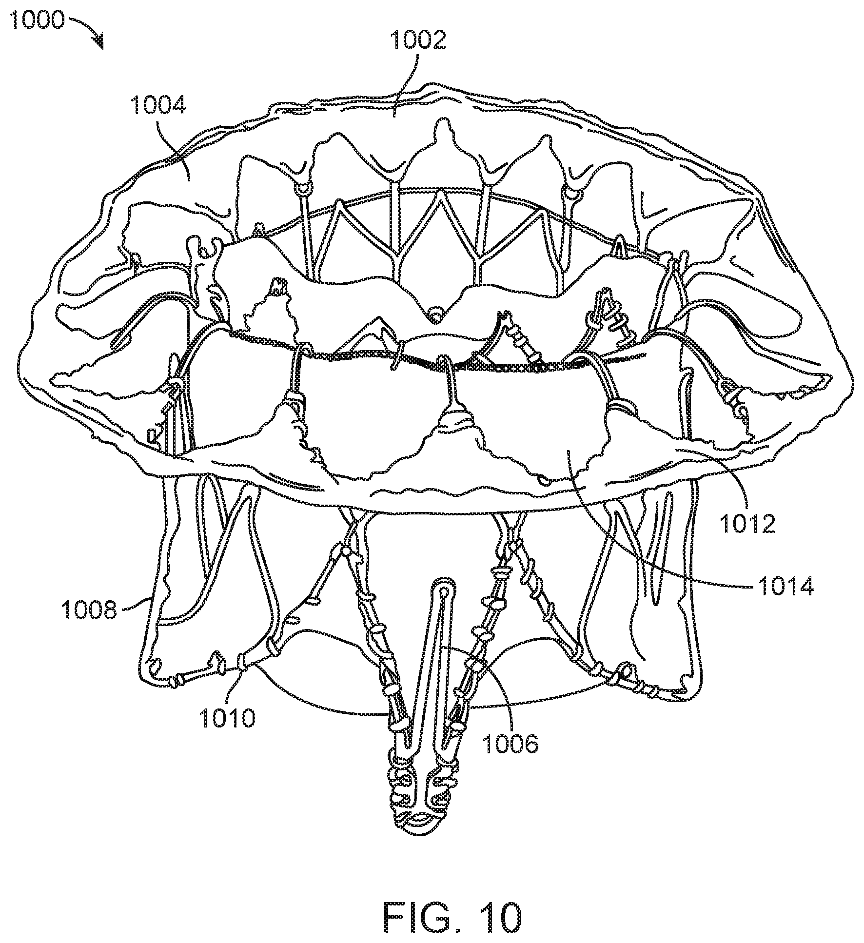
D00014

D00015

D00016

D00017

D00018
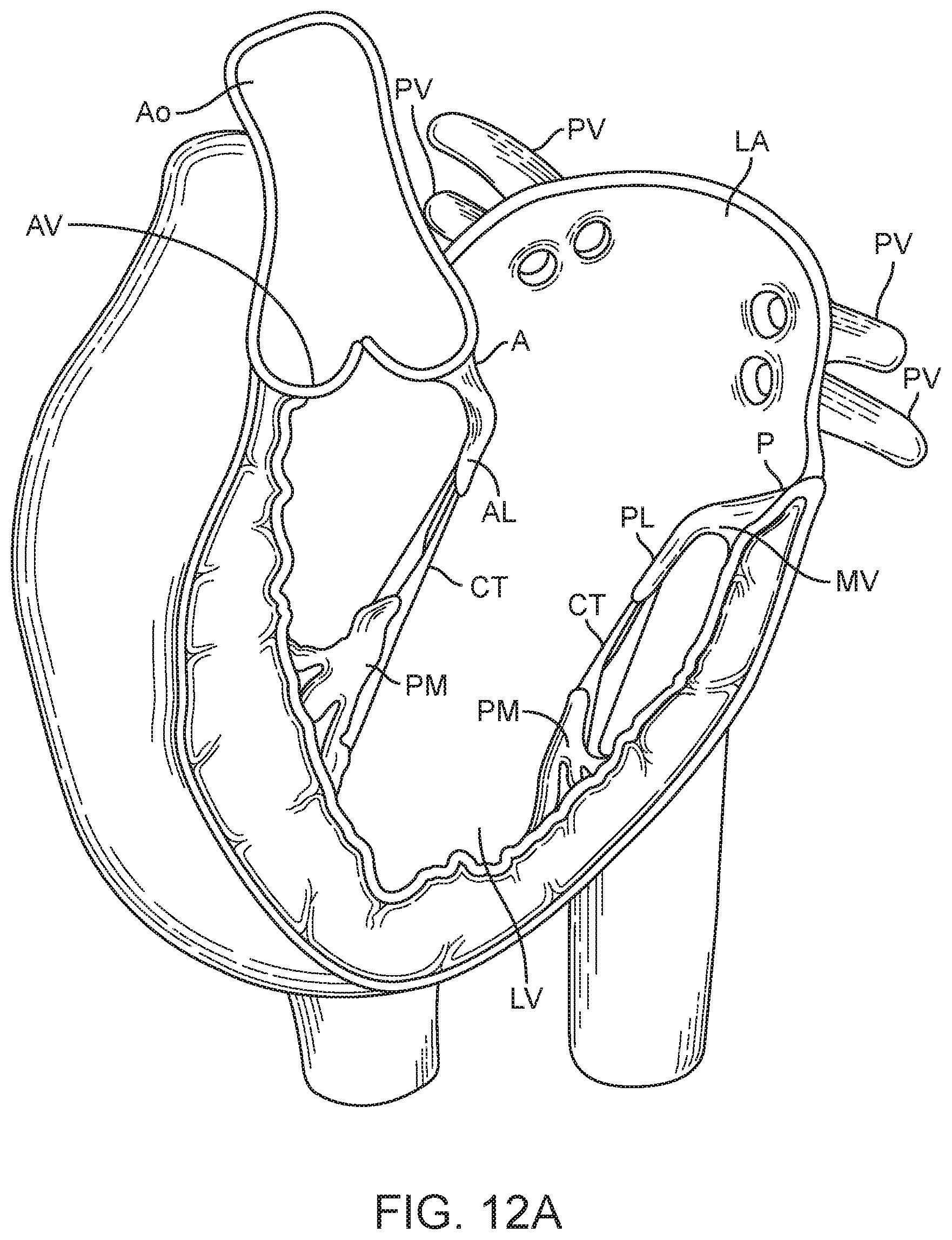
D00019

D00020

D00021

D00022

D00023
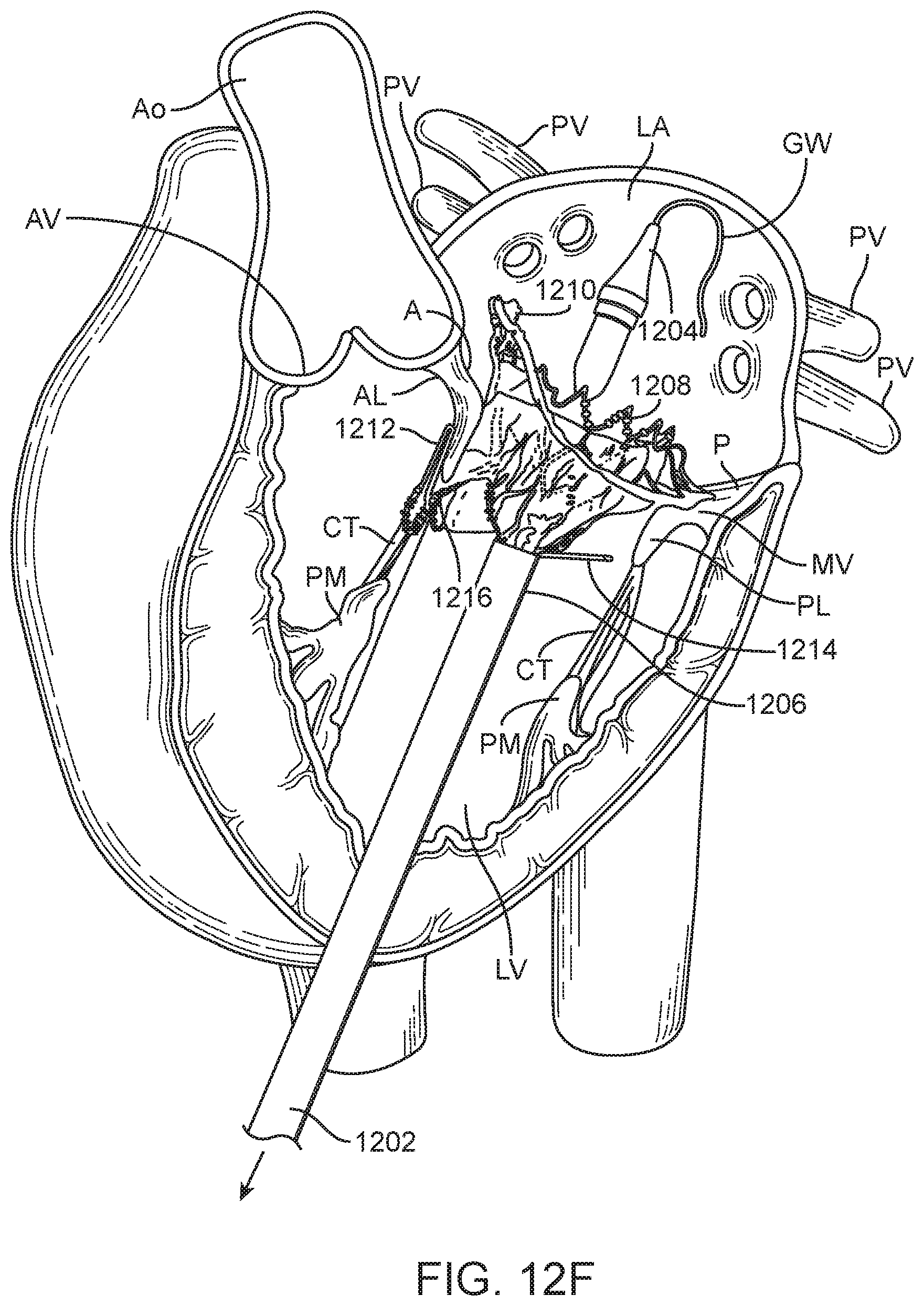
D00024

D00025

D00026

D00027
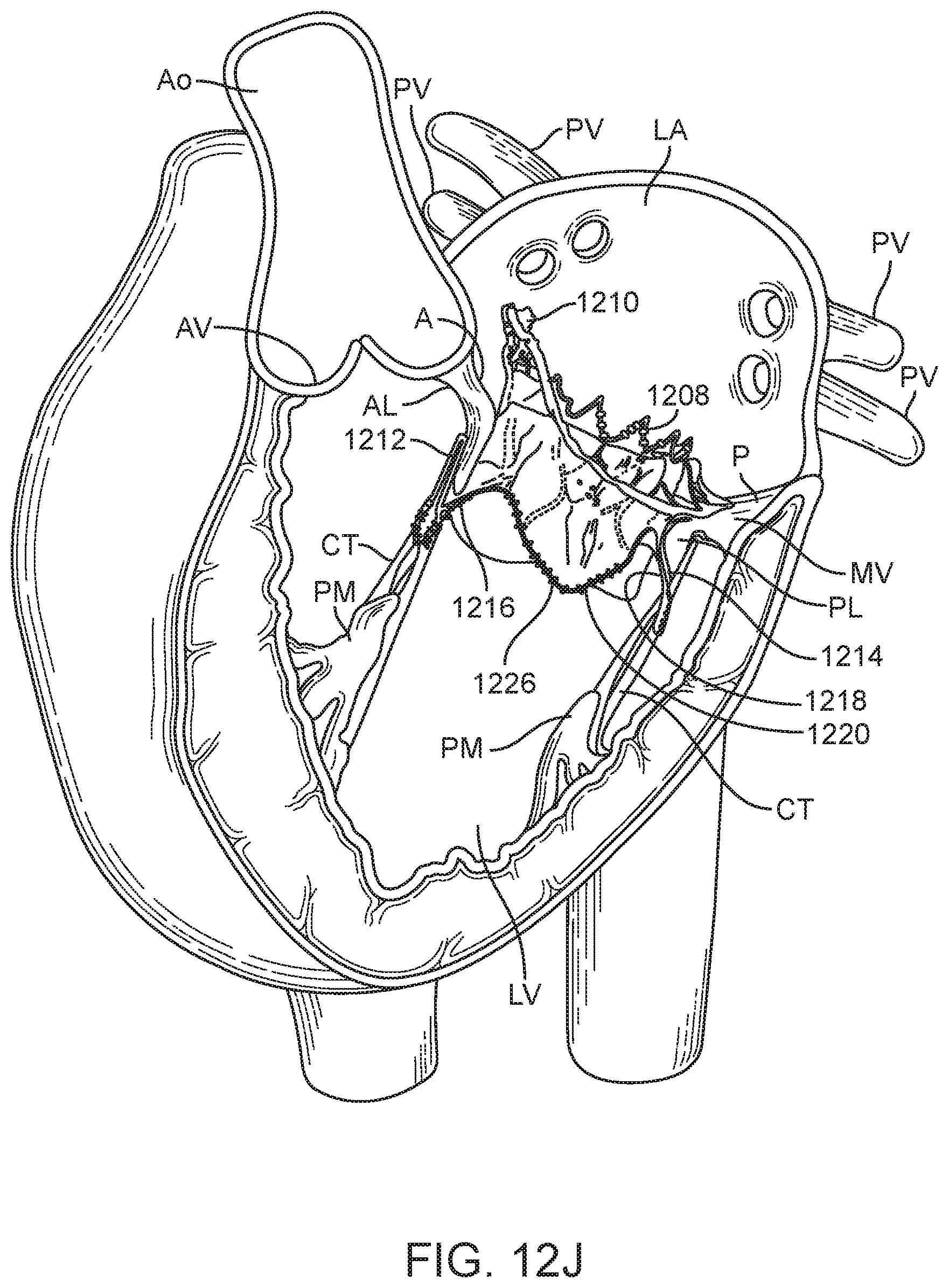
D00028

D00029

D00030

D00031
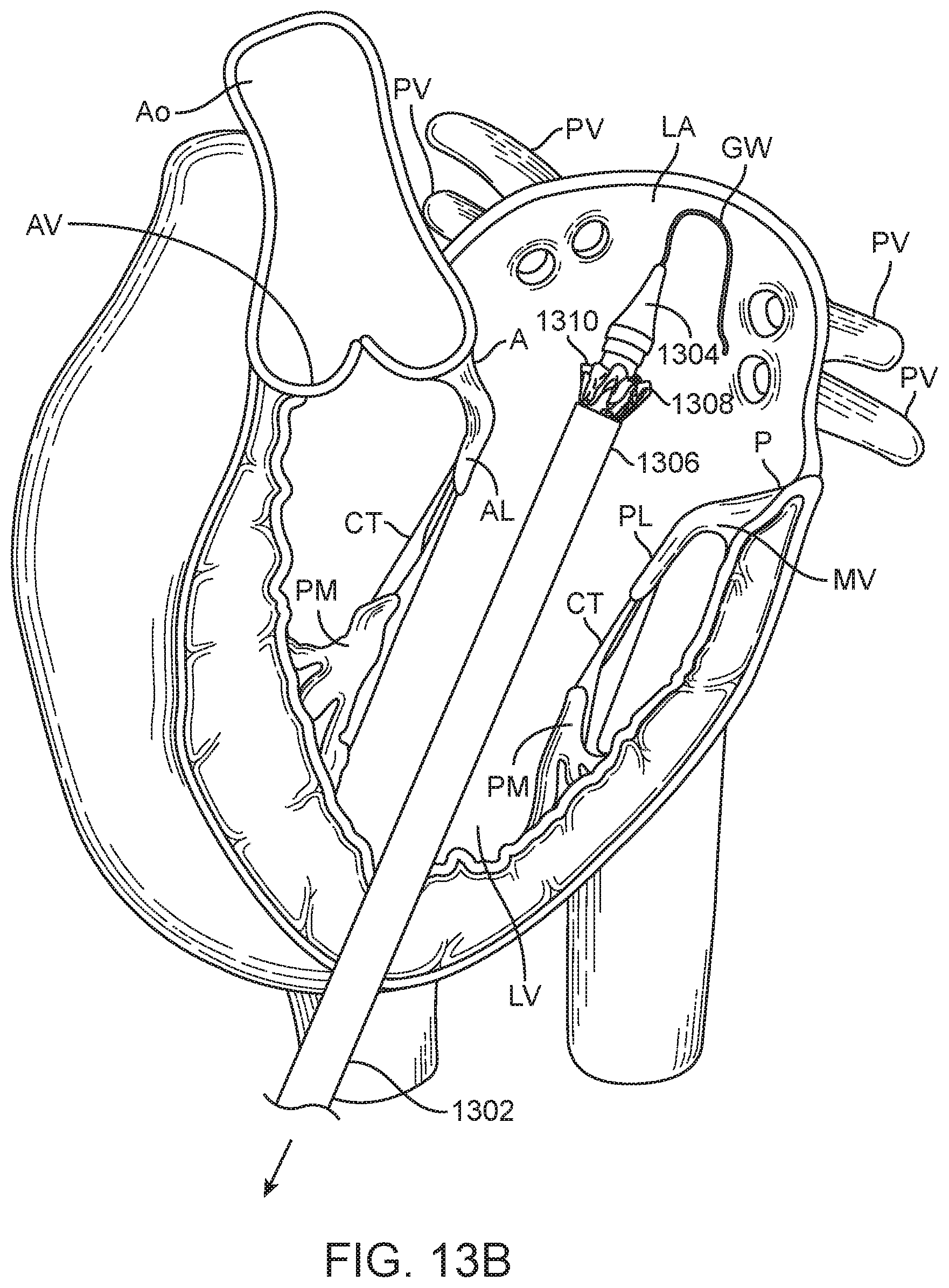
D00032

D00033
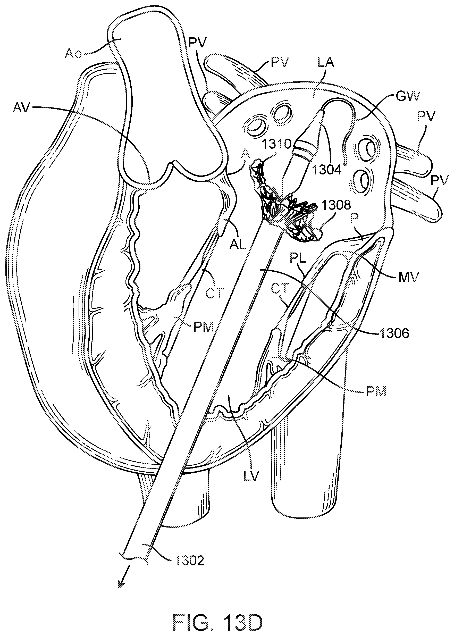
D00034
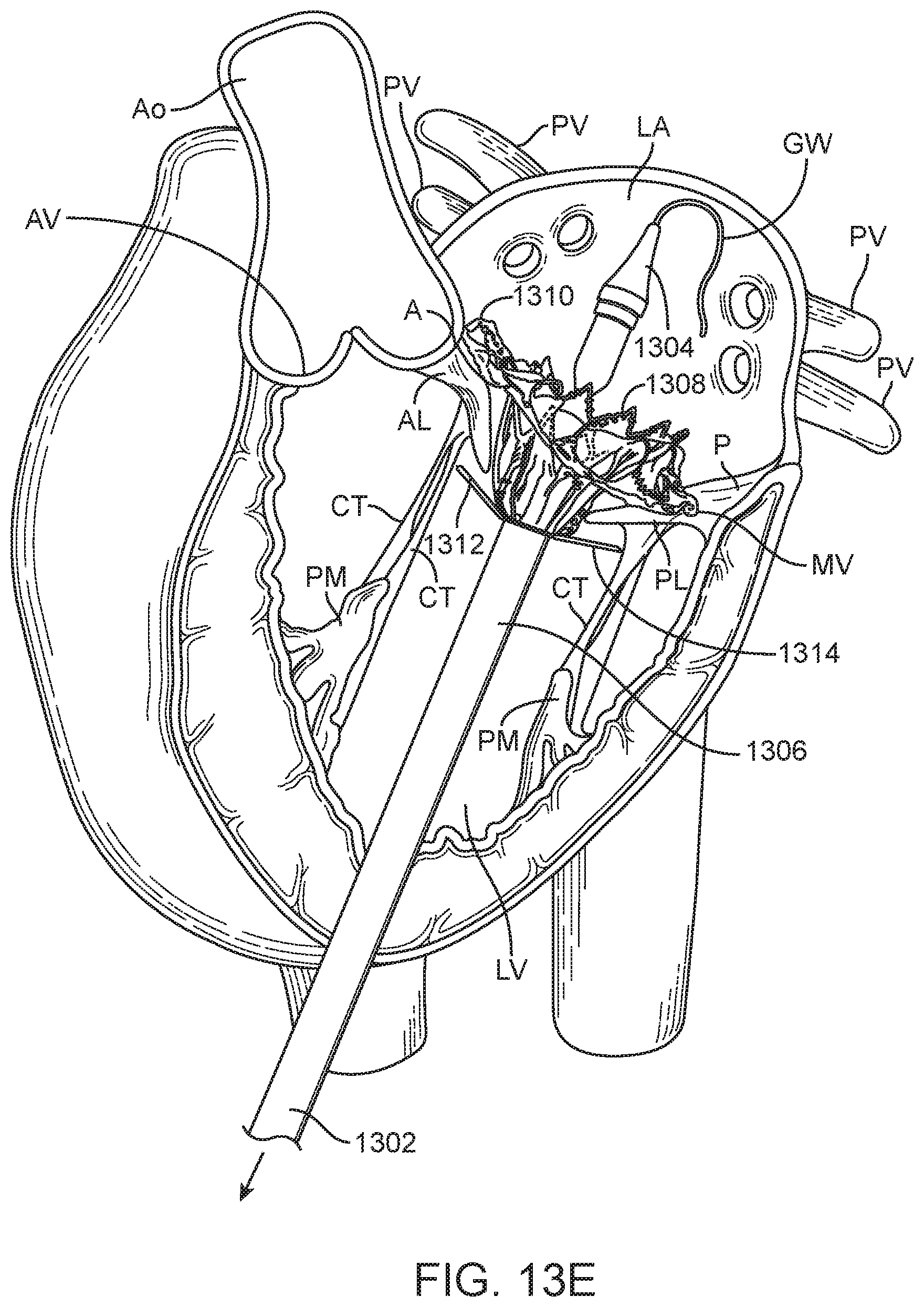
D00035

D00036

D00037
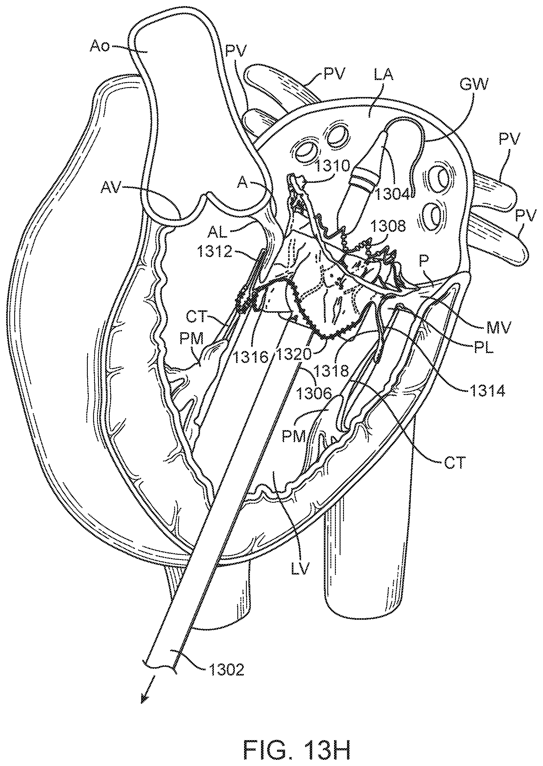
D00038
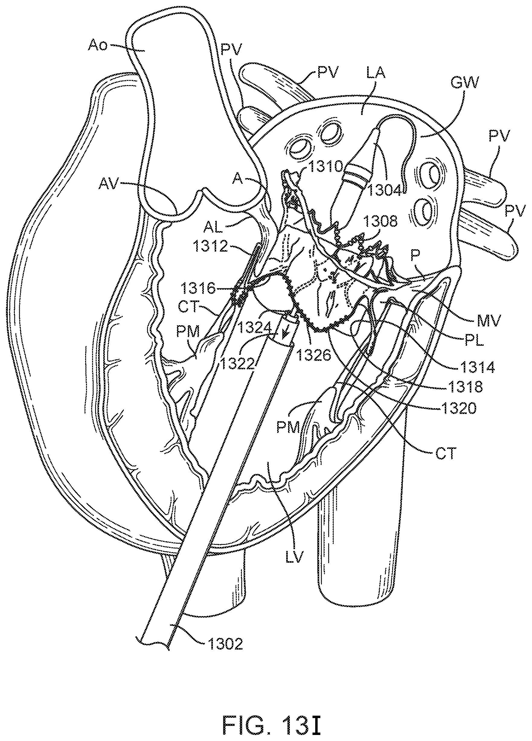
D00039
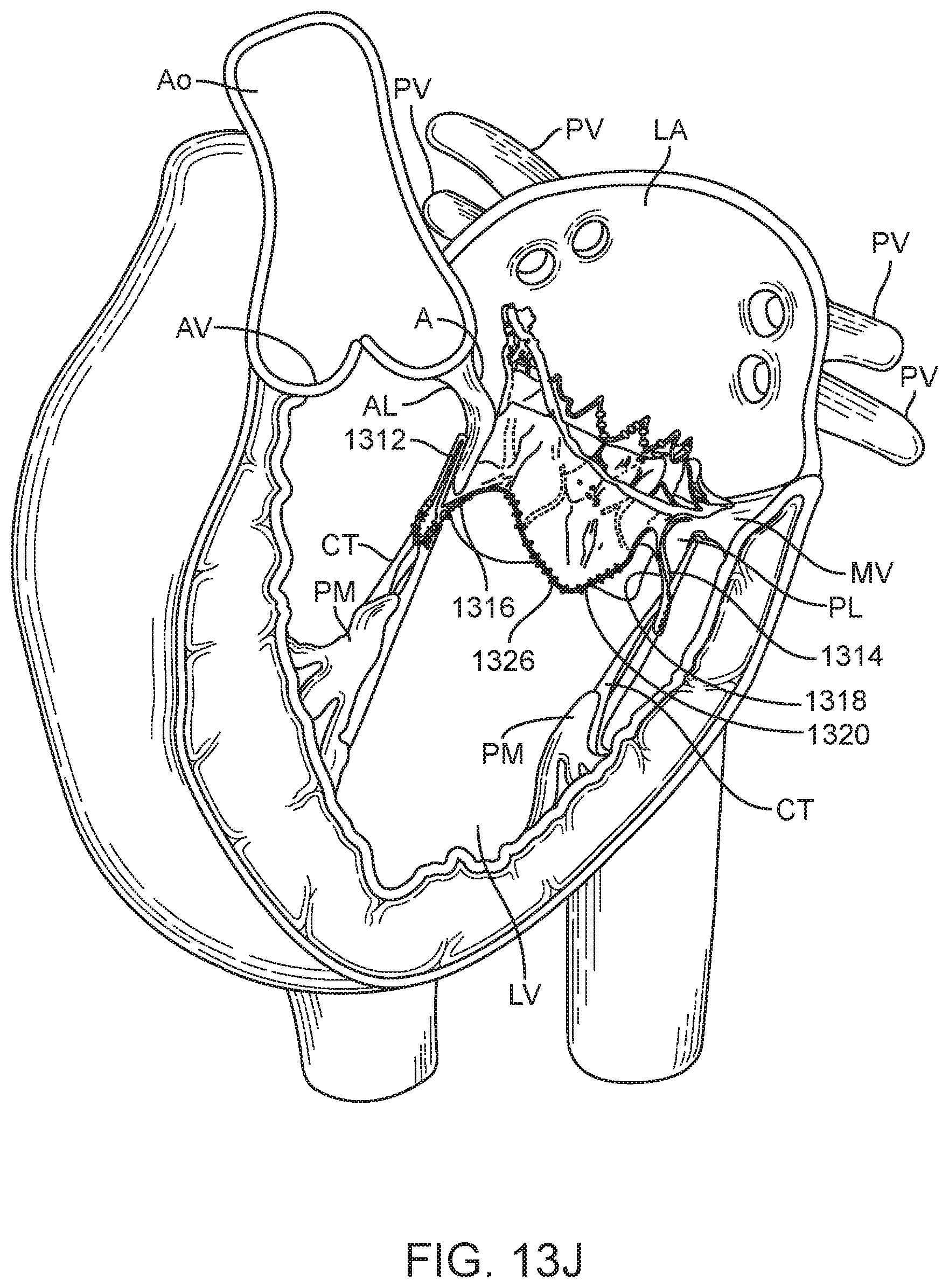
D00040
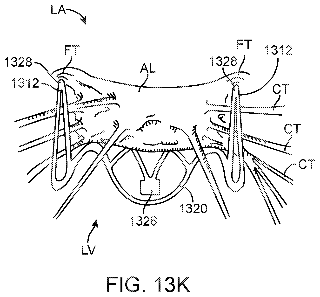
D00041

D00042
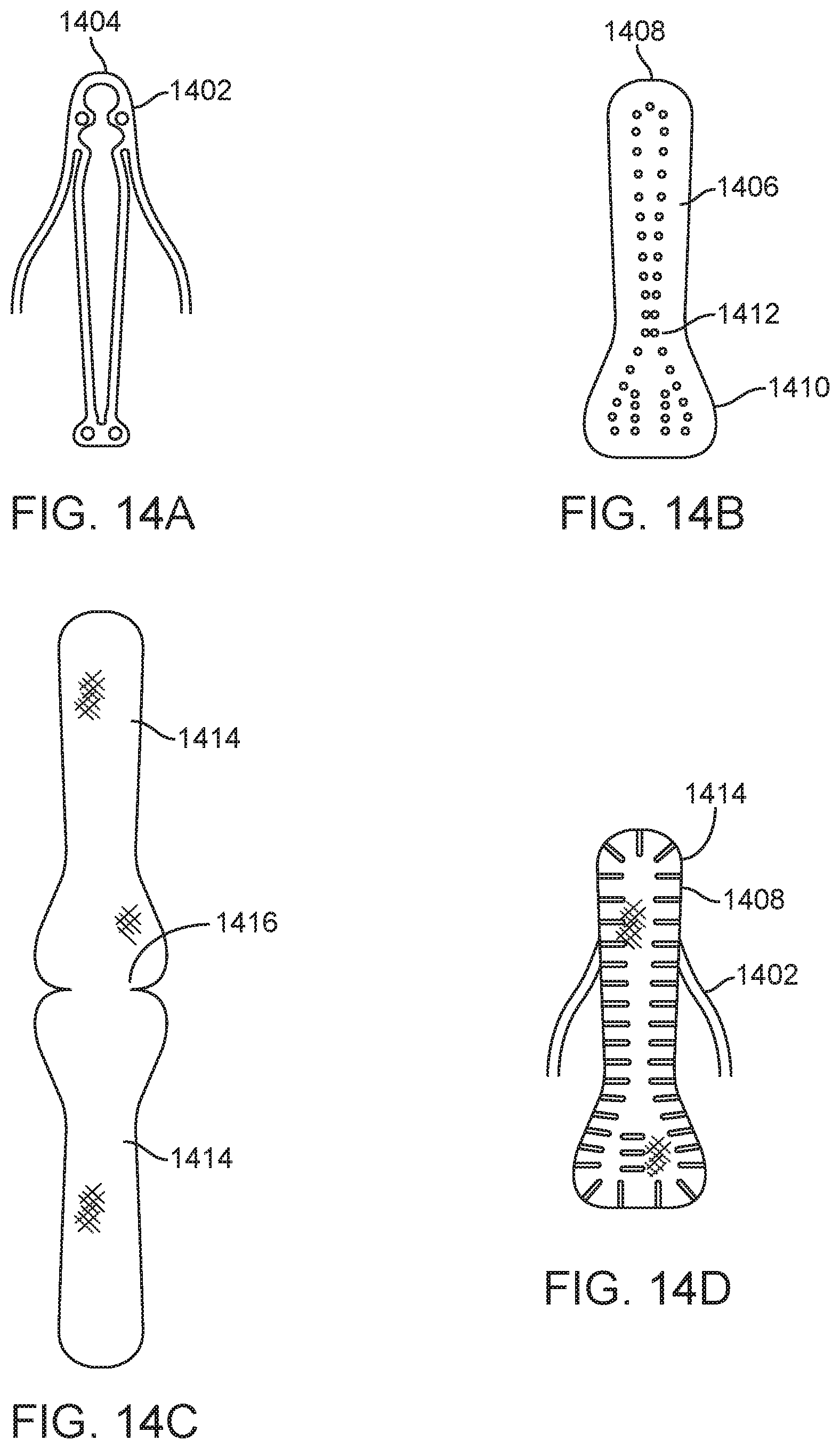
XML
uspto.report is an independent third-party trademark research tool that is not affiliated, endorsed, or sponsored by the United States Patent and Trademark Office (USPTO) or any other governmental organization. The information provided by uspto.report is based on publicly available data at the time of writing and is intended for informational purposes only.
While we strive to provide accurate and up-to-date information, we do not guarantee the accuracy, completeness, reliability, or suitability of the information displayed on this site. The use of this site is at your own risk. Any reliance you place on such information is therefore strictly at your own risk.
All official trademark data, including owner information, should be verified by visiting the official USPTO website at www.uspto.gov. This site is not intended to replace professional legal advice and should not be used as a substitute for consulting with a legal professional who is knowledgeable about trademark law.