Venous Valve, System, and Method
Hill; Jason P. ; et al.
U.S. patent application number 13/226172 was filed with the patent office on 2011-12-29 for venous valve, system, and method. This patent application is currently assigned to BOSTON SCIENTIFIC SCIMED, INC.. Invention is credited to Jason P. Hill, Jaydeep Y. Kokate, Susan M. Shoemaker.
| Application Number | 20110319981 13/226172 |
| Document ID | / |
| Family ID | 37189039 |
| Filed Date | 2011-12-29 |


View All Diagrams
| United States Patent Application | 20110319981 |
| Kind Code | A1 |
| Hill; Jason P. ; et al. | December 29, 2011 |
Venous Valve, System, and Method
Abstract
A venous valve with a frame and a cover on the frame for unidirectional flow of a liquid through the valve.
| Inventors: | Hill; Jason P.; (Cottage Grove, MN) ; Shoemaker; Susan M.; (Elk River, MN) ; Kokate; Jaydeep Y.; (Maple Grove, MN) |
| Assignee: | BOSTON SCIENTIFIC SCIMED,
INC. Maple Grove MN |
| Family ID: | 37189039 |
| Appl. No.: | 13/226172 |
| Filed: | September 6, 2011 |
Related U.S. Patent Documents
| Application Number | Filing Date | Patent Number | ||
|---|---|---|---|---|
| 11150331 | Jun 10, 2005 | 8012198 | ||
| 13226172 | ||||
| Current U.S. Class: | 623/1.24 |
| Current CPC Class: | A61F 2220/0075 20130101; A61F 2/2412 20130101; A61B 90/39 20160201; A61F 2/2475 20130101; A61F 2250/0098 20130101; A61F 2220/005 20130101; A61F 2/2418 20130101; A61F 2230/0013 20130101; A61F 2/2409 20130101; A61F 2220/0016 20130101; A61F 2220/0066 20130101 |
| Class at Publication: | 623/1.24 |
| International Class: | A61F 2/82 20060101 A61F002/82 |
Claims
1-41. (canceled)
42. A valve having a first end and a second end, the valve comprising: a frame, the frame comprising: a first frame end having only two first frame end turns, the two first frame end turns forming the first end of the valve; and a second frame end comprising a plurality of second frame end turns, the plurality of second frame end turns forming the second end of the valve, the plurality of second frame end turns forming a part of a tubular ring having a serpentine configuration, a plurality of frame members connecting the two first frame end turns to the tubular ring; and a plurality of valve leaflets engaged to the frame.
43. The valve of claim 42, the plurality of frame members being four frame members, wherein two frame members connect one of the two first frame end turns to the tubular ring and two frame members connect the other of the two first frame end turns to the tubular ring.
44. The valve of claim 42, each first frame end turn having three frame members engaged thereto.
45. The valve of claim 44, each of the plurality of frame members having a body portion and two legs, each first frame end turn engaged to the body portion of the three frame members.
46. The valve of claim 45, the tubular ring further comprising a plurality of ring turns engaged to the second frame end turns by struts, each ring turn engaged to a leg of one of the plurality of frame members.
47. The valve of claim 45, the plurality of frame members including first frame members having a first shape and second frame members having a second shape different than the first shape.
48. The valve of claim 47, the frame having two first frame members and four second frame members.
49. The valve of claim 48, each leg of a first frame member engaged to a ring turn of the tubular ring, a first leg of each second frame member engaged to a ring turn of the tubular ring, and a second leg of a second frame member engaged to a second leg of another second frame member.
50. The valve of claim 45, each first frame member being between two second frame members.
51. The valve of claim 42, the frame defining: a plurality of first cells each having a first configuration; a plurality of second cells each having a second configuration; and a plurality of third cells each having a third configuration; the first, second, and third configurations being different configurations.
52. The valve of claim 42, the plurality of leaflets comprising a first valve leaflet and a second valve leaflet, the valve further comprising: a cover comprising a first cover end, the first cover end attached to the tubular ring; a second cover end region, the second cover end region forming the first valve leaflet and the second valve leaflet; and a second cover end, the second cover end engaged to the two first frame end turns.
53. A valve comprising: a frame, the frame comprising: a first tubular ring forming a first end of the valve; a second tubular ring forming a second end of the valve; a first frame member comprising a body portion and two legs, the body portion connected to the first tubular ring and each leg connected to the second tubular ring; and a second frame member comprising a body portion and two legs, the body portion connected to the first tubular ring and each leg connected to the second tubular ring a plurality of valve leaflets engaged to the frame.
54. The valve of claim 53, the second tubular ring having a serpentine configuration, the first cover end attached to the second tubular ring, the first cover end having a serpentine configuration that is the same as the serpentine configuration of the second tubular ring.
55. The valve of claim 53, the first and second ends of the valve flaring outwards.
56. The valve of claim 53, the plurality of leaflets comprising a first valve leaflet and a second valve leaflet, the valve further comprising: a cover, the cover comprising a first cover end, a second cover end region, and a second cover end, the cover attached to the frame, the cover extending from the one end of the valve so that the first cover end is a distance away from the other end of the valve, the second cover end region of the cover comprising the first valve leaflet and the second valve leaflet.
57. The valve of claim 56, the body portion of the first frame member defining a first through hole, the body portion of the second frame member defining a second through hole, the cover attached to the frame at the first and second through holes.
58. The valve of claim 57, the second cover end region further comprising a first flap and a second flap, the first flap positioned adjacent to the first through hole, the second flap positioned adjacent to the second through hole, the cover being attached to the inner surface of the frame wherein the first and second flaps are each wrapped around the frame from the inner surface to the outer surface through the first and second through holes.
59. The valve of claim 56, the first cover end having a first diameter, the second cover end having a second diameter, the first diameter being smaller than the second diameter.
60. The valve of claim 56, the cover attached to the frame at a first leaflet connection and at a second leaflet connection, the first valve leaflet and the second valve leaflet each extending between the first and second leaflet connections, the first leaflet opposite the second leaflet, each leaflet having a concave shaped edge, the concave shaped edges of the first and second valve leaflets being the second cover end.
61. A valve comprising a first end, a second end, a frame, and a plurality of valve leaflets engaged to the frame, the frame comprising: a first frame member, the first frame member extending from the first end of the valve to the second end of the valve, the first frame member forming a closed loop, and a second frame member, the second frame member extending from the first end of the valve to the second end of the valve, the second frame member forming a closed loop; a first portion of the first frame member and a first portion of the second frame member being side-by-side and joined thereat; and a second portion of the first frame member and a second portion of the second frame member being side-by-side and joined thereat.
Description
FIELD OF THE INVENTION
[0001] The present invention relates to apparatus, systems, and methods for use in a lumen; and more particularly to a valve apparatus, systems, and methods for use in the vasculature system.
BACKGROUND OF THE INVENTION
[0002] The venous system of the legs uses valves and muscles as part of the body's pumping mechanism to return blood to the heart. Venous valves create one way flow to prevent blood from flowing away from the heart. When valves fail, blood can pool in the lower legs resulting in swelling and ulcers of the leg. The absence of functioning venous valves can lead to chronic venous insufficiency.
[0003] Techniques for both repairing and replacing the valves exist, but are tedious and require invasive surgical procedures. Direct and indirect valvuoplasty procedures are used to repair damaged valves. Transposition and transplantation are used to replace an incompetent valve. Transposition involves moving a vein with an incompetent valve to a site with a competent valve. Transplantation replaces an incompetent valve with a harvested valve from another venous site. Prosthetic valves can be transplanted into the venous system, but current devices are not successful enough to see widespread usage.
BRIEF DESCRIPTION OF THE DRAWINGS
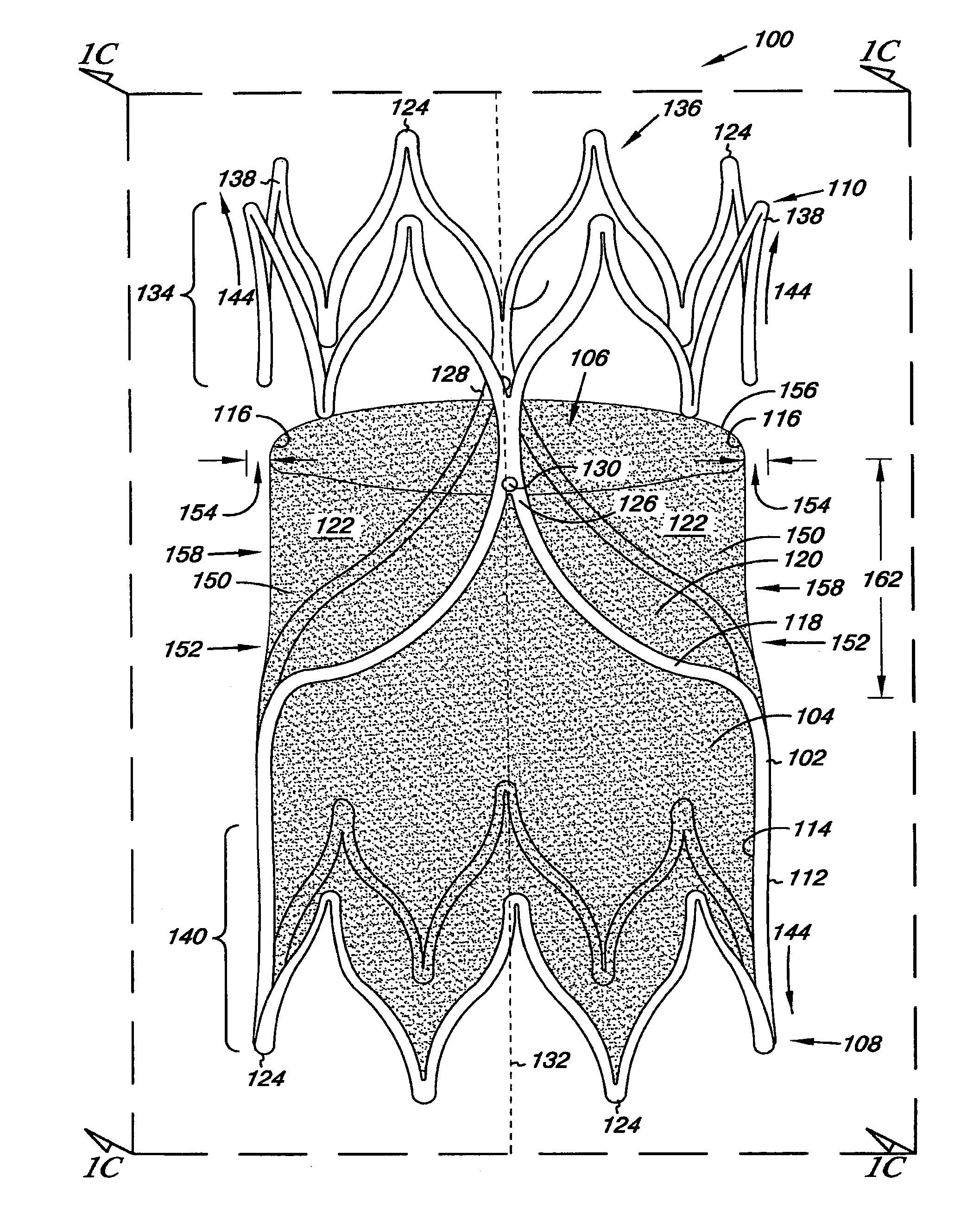
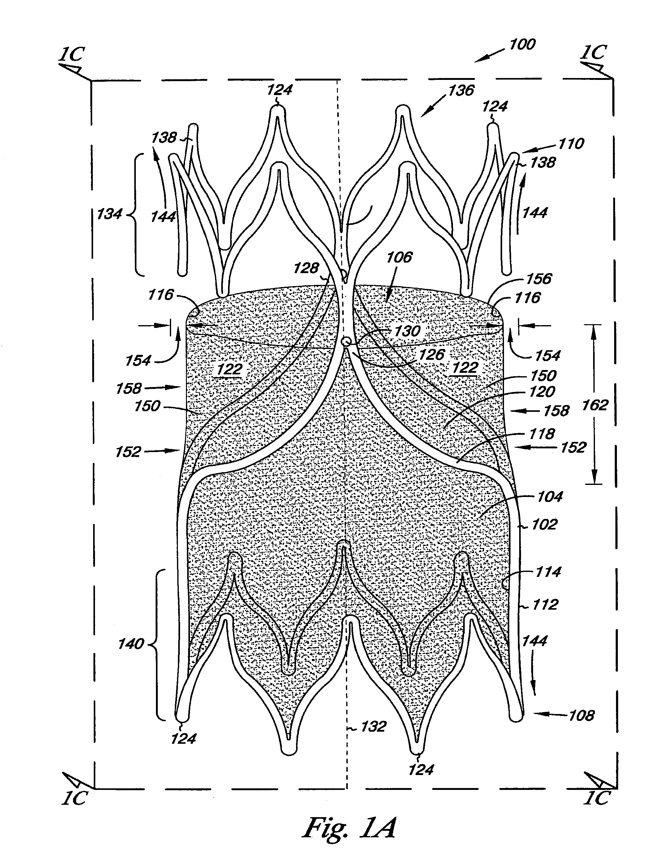
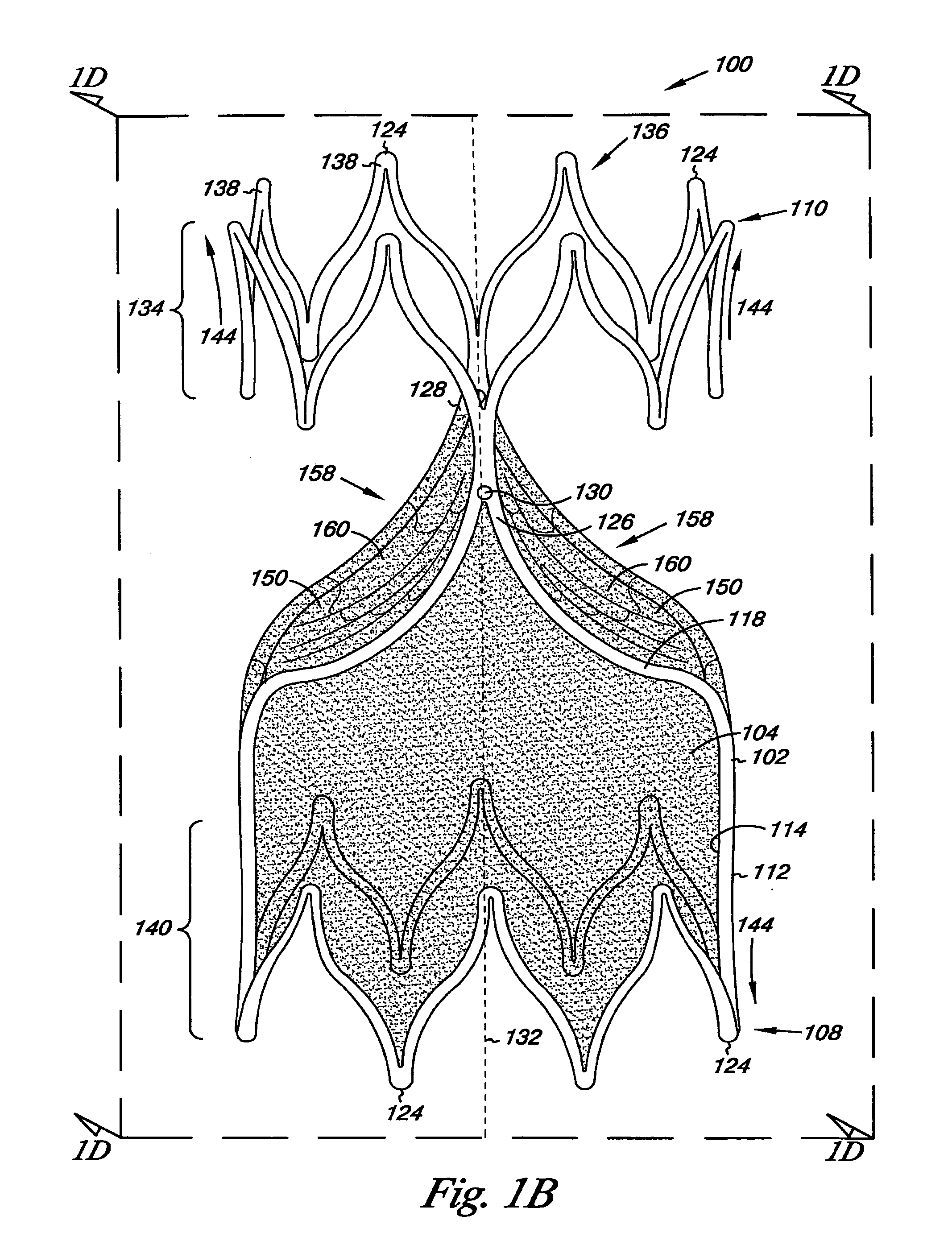
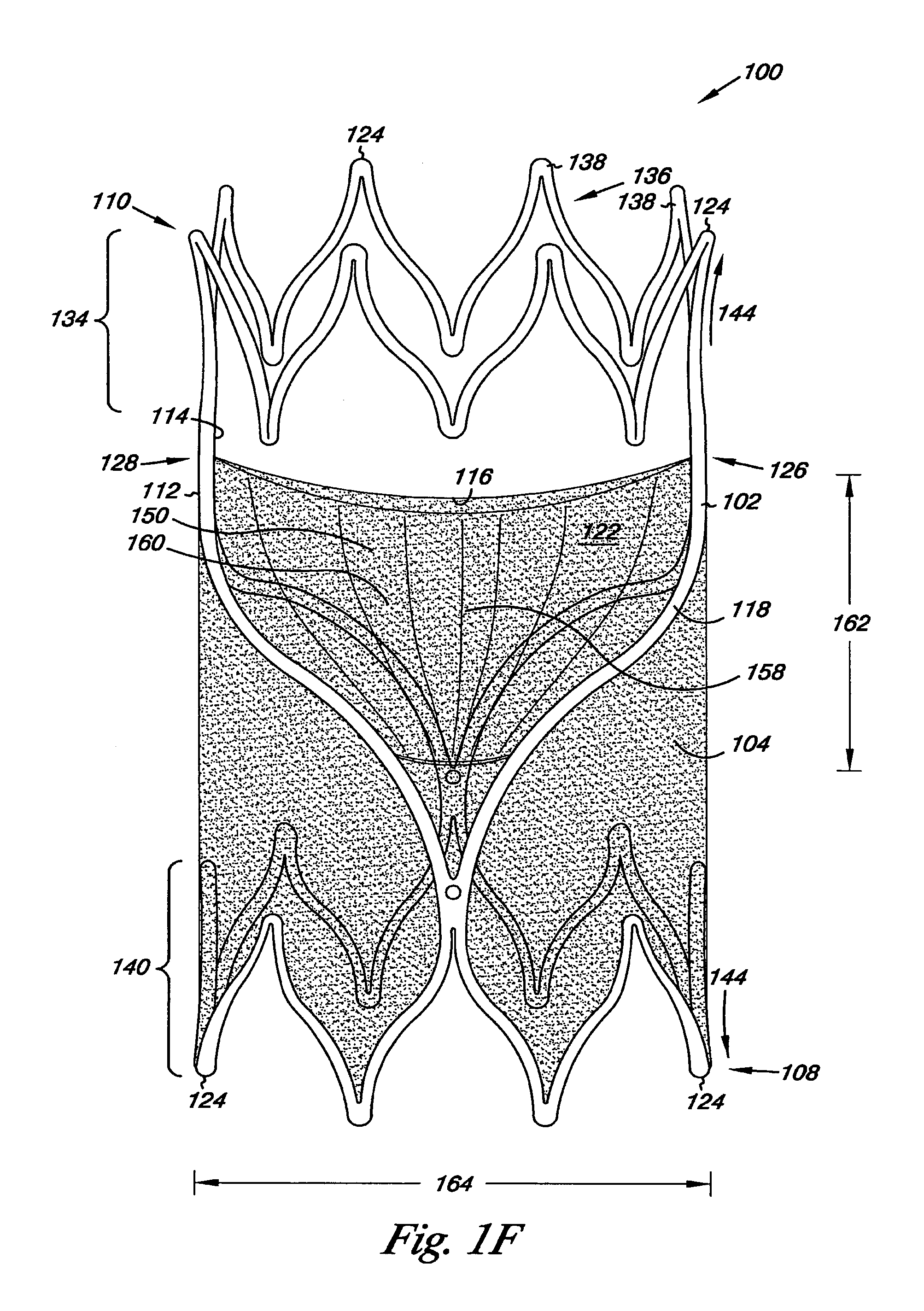
[0004] FIGS. 1A and 1B illustrate an embodiment of a valve according to the present invention.
[0005] FIG. 1C illustrates a cross-sectional view of the valve illustrated in FIG. 1A.
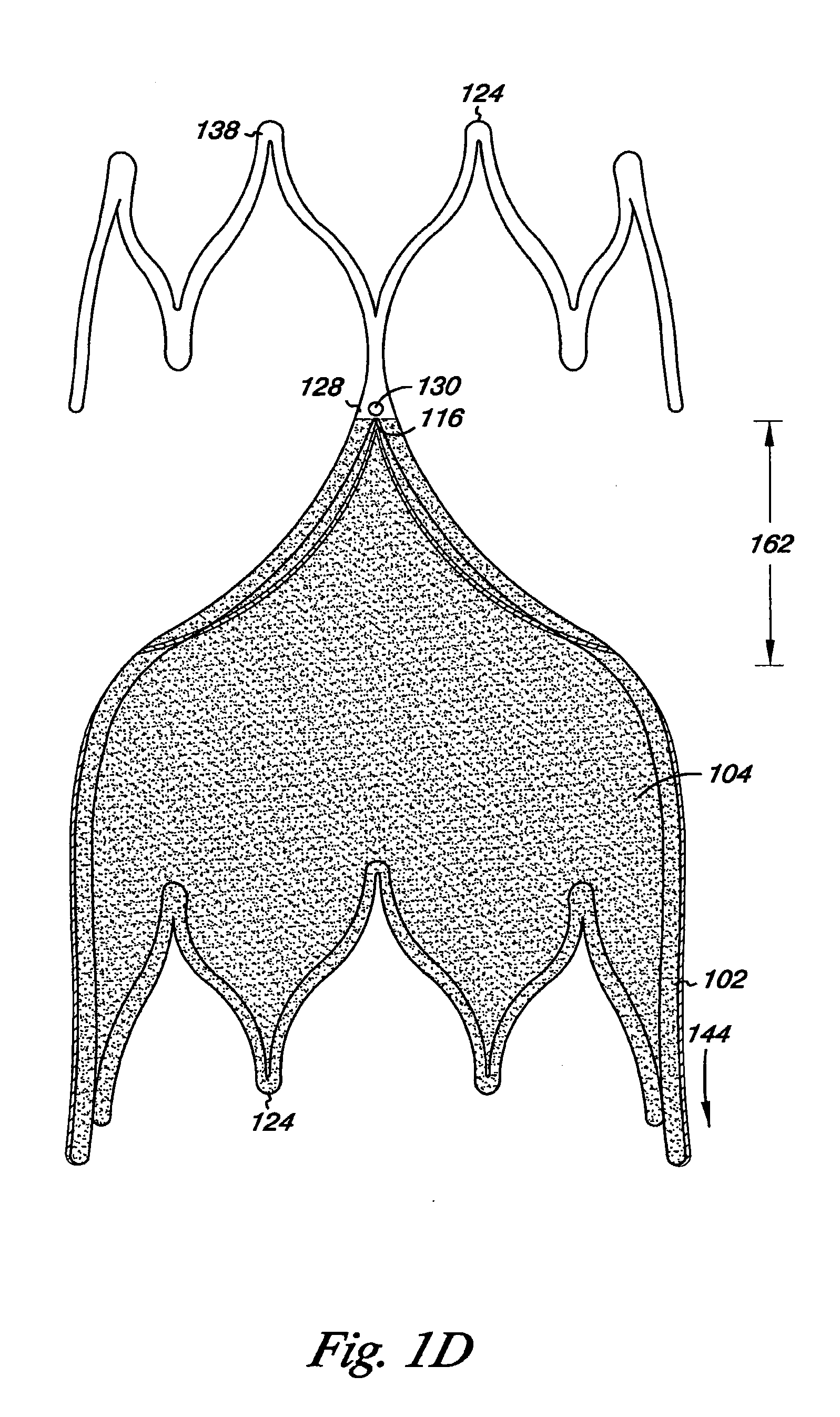
[0006] FIG. 1D illustrates a cross-sectional view of the valve illustrated in FIG. 1B.
[0007] FIGS. 1E and 1F illustrates an additional perspective view of the valve illustrated in FIG. 1A.
[0008] FIGS. 2A and 2B illustrate an embodiment of a valve in an expanded and collapsed state according to the present invention.
[0009] FIGS. 3A and 3B illustrate an embodiment of a valve according to the present invention.
[0010] FIG. 4A illustrates an embodiment of a valve according to the present invention.
[0011] FIG. 4B illustrates an embodiment of a valve according to the present invention.
[0012] FIG. 5A illustrates an embodiment of a valve according to the present invention.
[0013] FIG. 5B illustrates an embodiment of a frame for the valve illustrated in FIG. 5A according to the present invention.
[0014] FIG. 6 illustrates an embodiment of a system that includes a valve according to the present invention.
[0015] FIG. 7 illustrates an embodiment of a system that includes a valve according to the present invention.
[0016] FIG. 8 illustrates an embodiment of a system that includes a valve according to the present invention.
[0017] FIGS. 9A, 9B and 9C illustrate an embodiment of a system that includes a valve according to the present invention.
[0018] FIGS. 10A, 10B and 10C illustrate an embodiment of a system that includes a valve and a catheter having radiopaque markers according to the present invention.
DETAILED DESCRIPTION
[0019] Embodiments of the present invention are directed to an apparatus, system, and method for valve replacement or augmentation. For example, the apparatus can include a valve that can be used to replace or augment an incompetent valve in a body lumen. Embodiments of the valve can include a frame and cover that can be implanted through minimally-invasive techniques into the body lumen. In one example, embodiments of the apparatus, system, and method for valve replacement or augmentation may help to maintain antegrade blood flow, while decreasing retrograde blood flow in a venous system of individuals having venous insufficiency, such as venous insufficiency in the legs.
[0020] The figures herein follow a numbering convention in which the first digit or digits correspond to the drawing figure number and the remaining digits identify an element or component in the drawing. Similar elements or components between different figures may be identified by the use of similar digits. For example, 110 may reference element "10" in FIG. 1, and a similar element may be referenced as 210 in FIG. 2. As will be appreciated, elements shown in the various embodiments herein can be added, exchanged, and/or eliminated so as to provide a number of additional embodiments of valve. In addition, discussion of features and/or attributes for an element with respect to one Fig. can also apply to the element shown in one or more additional Figs. Embodiments illustrated in the figures are not necessarily to scale.
[0021] FIGS. 1A through 5B provide illustrations of various embodiments of a valve of the present invention. The valve can be implanted within the fluid passageway of a body lumen, such as for replacement or augmentation of a valve structure within the body lumen (e.g., a venous valve). In one embodiment, the valve of the present invention may be beneficial to regulate the flow of a bodily fluid through the body lumen in a single direction.
[0022] FIGS. 1A-1F illustrate one embodiment of a venous valve 100. Venous valve 100 includes a frame 102 and a cover 104 for the venous valve 100, where both the frame 102 and the cover 104 can resiliently radially collapse and expand, as will be described herein. Among other things, the frame 102 and the cover 104 define a lumen 106 of the valve 100. The lumen 106 allows for, amongst other things, fluid (e.g., blood) to move through the valve 100. The frame 102 also includes a first end 108 and a second end 110. The first end 108 and the second end 110 define a length of the frame 102 and of the valve 100. In one embodiment, the length of valve 100 can have a number of values. As will be appreciated, the length of valve 100 can be determined based upon the location into which the valve 100 is to be implanted. In other words, the length of the valve 100 can be patient specific. Examples of values for the length include, but are not limited to, 12 millimeters to 32 millimeters. Other values are also possible.
[0023] The frame 102 further includes an outer surface 112 and an inner surface 114 opposite the outer surface 112. In one embodiment, the cover 104 can be located over at least the outer surface 112 of the frame 102. For example, the cover 104 can extend around a perimeter of the frame 102 so as to completely cover the outer surface 112 of the frame 102. In other words, the cover 104 extends over the outer surface 112 of the frame 102 so that there are no exposed portions of the outer surface 112 of the frame 102. In an additional embodiment, the cover 104 can also be located over at least the inner surface 114 of the frame 102, as illustrated in FIGS. 1A-1F. A further embodiment includes the cover 104 located over at least a portion of the outer surface 112 and at least a portion of the inner surface 114.
[0024] The cover 104 can further include surfaces defining a reversibly sealable opening 116 for unidirectional flow of a liquid through the lumen 106. For example, the surfaces of the cover 104 can be deflectable between a closed configuration in which fluid flow through the lumen 106 can be restricted and an open configuration in which fluid flow through the lumen 106 can be permitted.
[0025] The frame 102 can be formed from a wide variety of materials and in a wide variety of configurations. Frame 102 can have a unitary structure with an open frame configuration. For example, the open frame configuration can include frame members 118 that define openings 120 across the frame 102 through which valve leaflets 122 formed by the cover 104 can radially-collapse and radially-expand, as will be described herein.
[0026] In addition, the first end 108 and the second end 110 each include a plurality of end portions 124 that lay on a common plane. The plurality of end portions 124, however, need not all lay on the common plane. In other words, it is possible that one or more of the end portions 124 of the frame 102 lay above and/or below the common plane.
[0027] While the frames illustrated herein, for example frame 102, are shown as having a circular configuration, other configurations are also possible. For example, the frame 102 could have an elliptical configuration. As such, the present invention should not be limited to the illustration of the frames, such as frame 102, provided herein.
[0028] As illustrated in FIGS. 1A-1F, the frame 102 can further include a first leaflet connection region 126 and a second leaflet connection region 128 adjacent the second end 110 of the frame 102. The first and second leaflet connection regions 126 and 128 further include an opening 130 through the frame 102. In the present example, the cover 104 can be coupled, as described more fully herein, to at least the first leaflet connection region 126 and the second leaflet connection region 128 using the openings 130 through the frame 102. The cover 104 so coupled can then move (e.g., pivot) relative the first leaflet connection region 126 and the second leaflet connection region 128 between an open valve configuration (illustrated in FIGS. 1A, 1C, and 1E) and a closed valve configuration (illustrated in FIGS. 1B, 1D, and 1F). As illustrated in the closed valve configuration, the open frame configuration of frame 102 allows cover 104 to move through the openings 120 in creating the reversible sealable opening 116 of the valve 100.
[0029] As illustrated in FIGS. 1A-1B and 1E-1F, the first leaflet connection region 126 and the second leaflet connection region 128 can be positioned opposite each other along a common axis. In addition, the first leaflet connection region 126 and the second leaflet connection region 128 can be radially symmetric around the longitudinal central axis 132 of the frame 102.
[0030] As illustrated, the first leaflet connection region 126 and the second leaflet connection region 128 can be positioned approximately one hundred eighty (180) degrees relative each other around the longitudinal central axis 132 of the frame 102. As will be appreciated, the first and second leaflet connection regions 126, 128 need not necessarily display an equally spaced symmetrical relationship as described above in order to practice the embodiments of the present invention. For example, the radial relationship can have the first and second leaflet connection region 126, 128 positioned at values greater than one hundred eighty (180) degrees and less than one hundred eighty (180) degrees relative each other around the longitudinal central axis 132 of the frame 102.
[0031] The frame member 118 of frame 102 can have similar and/or different cross-sectional geometries and/or cross-sectional dimensions along its length. The similarity and/or the differences in the cross-sectional geometries and/or cross-sectional dimensions can be based on one or more desired functions to be elicited from each portion of the frame 102. For example, the frame member 118 can have a similar cross-sectional geometry along its length. Examples of cross-sectional geometries include, but are not limited to, round (e.g., circular, oval, and/or elliptical), rectangular geometries having perpendicular sides, one or more convex sides, or one or more concave sides; semi-circular; triangular; tubular; I-shaped; T shaped; and trapezoidal.
[0032] Alternatively, the cross-sectional dimensions of one or more geometries of the frame member 118 can change from one portion of the frame 102 to another portion of the frame 102. For example, portions of the frame member 118 can taper (i.e., transition) from a first geometric dimension to a second geometric dimension different than the first geometric dimension. These embodiments, however, are not limited to the present examples as other cross-sectional geometries and dimension are also possible. As such, the present invention should not be limited to the frames provided in the illustration herein.
[0033] The valve 100 can further include a radial support member 134. The radial support member 134 can include a number of different configurations, as will be described herein. For example, as illustrated the radial support member 134 couples the first leaflet connection region 126 and the second leaflet connection region 128. In addition to coupling the connection regions 126 and 128, the radial support member 134 can also serve to stabilize the relative positions of the connection regions 126 and 128 (e.g., limit relative fluctuations of the connection regions 126 and 128).
[0034] In the present embodiment, the radial support member 134 can be in the form of a tubular ring 136. The tubular ring 136 joins to the first leaflet connection region 126 and the second leaflet connection region 128. The tubular ring 136 can also move radially with the first and second leaflet connection region 124, 126 as the valve 100 radially collapses and expands.
[0035] In the various embodiments described herein, the tubular ring 136 can be configured to provide a spring force (e.g., elastic potential energy) to counter radial compression of the frame 102 towards its uncompressed state. For example, the tubular ring 136 can have a zig-zag configuration that includes corners 138 in from which a spring force (e.g., elastic potential energy) can be derived when the frame 102 is compressed. As will be appreciated, the corners 138 can have a number of configurations, including turns defining angles and/or arcs (e.g., having a radius of curvature). Additional spring force can be imparted to the frame 102 from the compression of the corners adjacent the first and second leaflet connection regions 126, 128 as well.
[0036] The valve 100 can further include a second tubular ring 140 located at the first end 108 of the frame 102. The second tubular ring 140 can have a similar, or different, configuration as tubular ring 136 so as to impart the spring force to counter radial compression of the frame 102 towards its uncompressed state. In one embodiment, both the tubular ring 136 and the second tubular ring 140 help to stabilize the relative positions of the connection regions 126 and 128, as described herein, and to help maintain the position of the connection regions 126 and 128 relative the walls of a lumen in which the valve 100 has been implanted. As will be appreciated, the valve 100 could further include additional tubular rings located at one or more positions along the frame 102.
[0037] The compressible nature of the valve 100 can accommodate changes in body lumen size (e.g., diameter of the body lumen) by flexing to expand and/or contract to change the diameter of the frame 102. In one embodiment, the corner portions of the tubular rings 136 and 140, and the first leaflet connection region 126 and the second leaflet connection region 128 can act as springs to allow the valve 100 to resiliently radially collapse and expand. The frame 102 can also provide sufficient contact and expansion force with the surface of a body lumen wall to encourage fixation of the valve 100 and to prevent retrograde flow within the body lumen around the edges of the frame 102 and the surface of a lumen when combined with a closed state of the valve leaflets attached thereto. Anchoring elements (e.g., barbs) can also be included with valve 100.
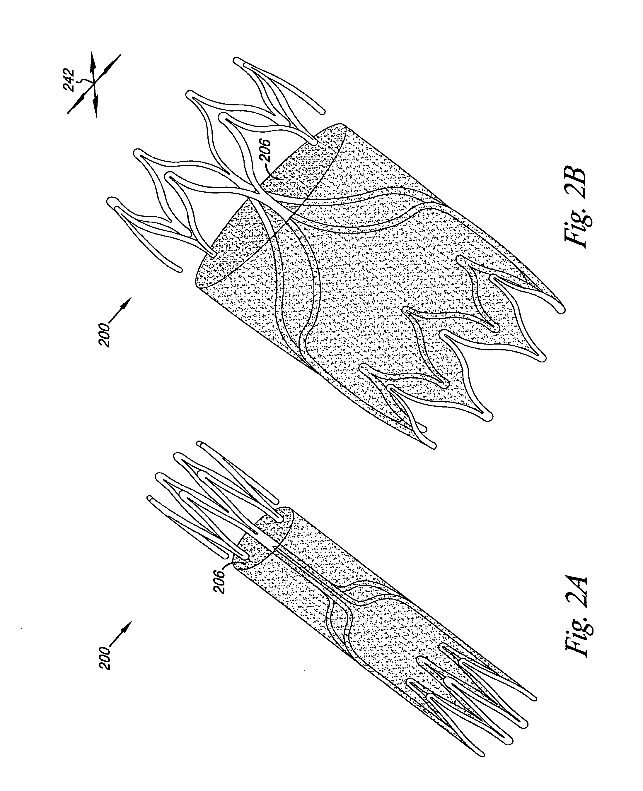
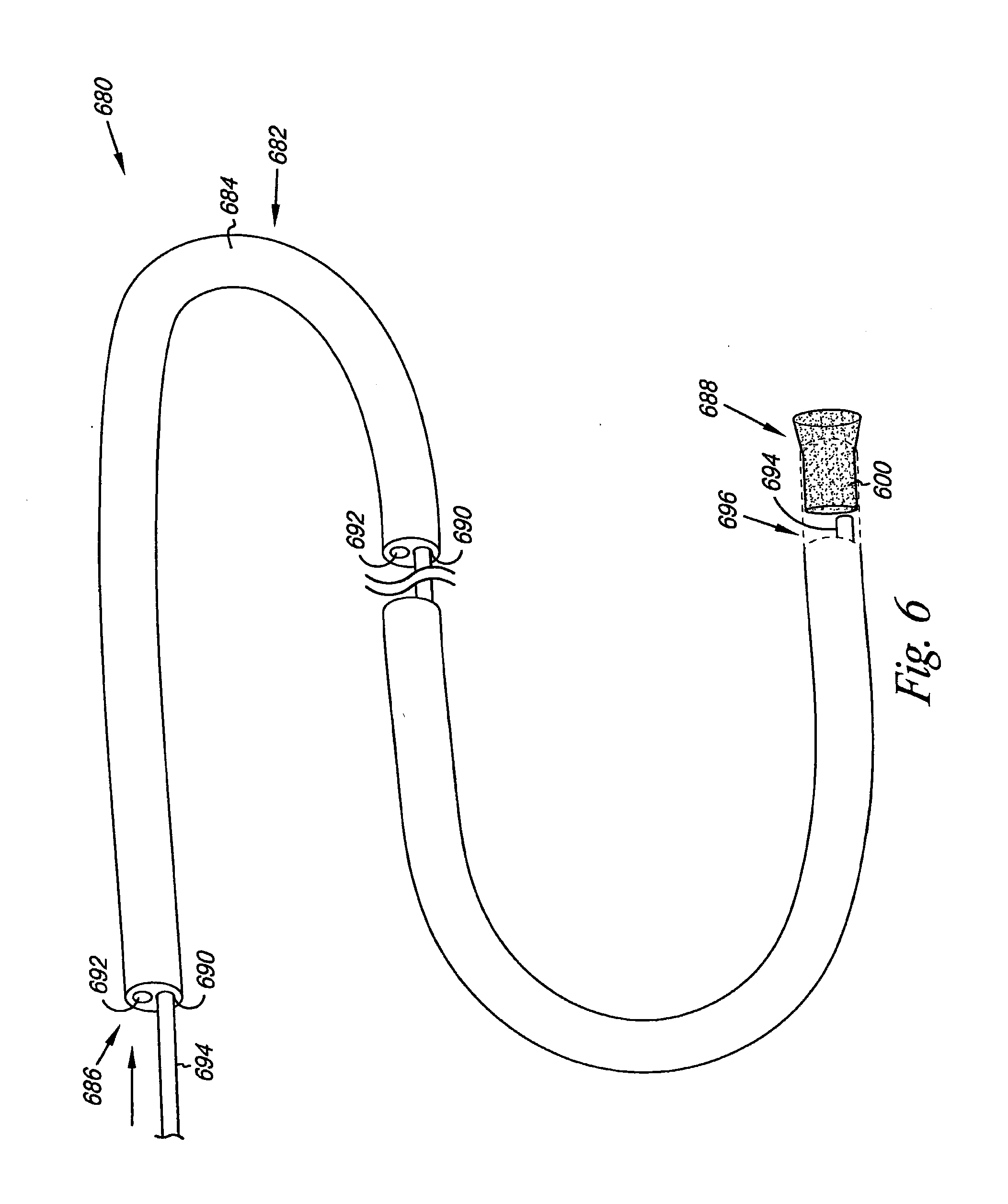
[0038] FIGS. 2A and 23 provide an example of the valve 200 in a collapsed state (FIG. 2A) and in an expanded state (FIG. 2B). As shown in FIGS. 2A and 2B, the valve 200 can travel between the collapsed and the expanded state along a radial travel path 240 (as shown in FIG. 2B), where there can be a change in a cross sectional area of lumen 206. For example, the frame 202 can travel along the radial travel path 242 so as to change a width of lumen 206. This can allow the valve 200 to react appropriately to the distension and contraction of a body lumen in which the valve 200 is placed.
[0039] Referring again to FIGS. 1A-1F, the corner portions of the tubular rings 136 and 140, and the first and second leaflet connection region 126 and 128 can also include, but are not limited to, other shapes that allow for repeatable travel between the collapsed state and the expanded state. For example, the elastic regions can include integrated springs having a circular or an elliptical loop configuration. The embodiments are not, however, limited to these configurations as other shapes are also possible.
[0040] The frame member 118 forming the tubular rings 136 and 140 can also include a radial flare 144. As illustrated, the radial flare 144 provides for an increase in the peripheral frame dimension at the first end 108 and/or the second end 110 of the frame 102. In one embodiment, the frame members 118 can be pre and/or post-treated to impart the radial flare 144. For example, frame members 118 forming the tubular rings 136 and 140 of the frame 102 could be bent to impart the radial flare 144. The frame 102 could then be heat treated so as to fix the radial flare 144 into the frame member 118. Other material treatments (e.g., plastic deformation, forging, elastic deformation with heat setting) are also possible to impart the radial flare as described herein, many of which are material specific.
[0041] The embodiments of the frame described herein can also be constructed of one or more of a number of materials and in a variety of configurations. The frame embodiments can have a unitary structure with an open frame configuration. The frame can also be self-expanding. Examples of self-expanding frames include those formed from temperature-sensitive memory alloy which changes shape at a designated temperature or temperature range, such as Nitinol. Alternatively, the self-expanding frames can include those having a spring-bias. In addition, the frame 102 can have a configuration that allows the frame embodiments be radially expandable through the use of a balloon catheter.
[0042] The embodiments of the frame, such as frame 102 in FIGS. 1A-1F, can also be formed from one or more contiguous frame members. For example, the frame member 118 of frame embodiments can be a single contiguous member. The single contiguous member can be bent around an elongate tubular mandrel to form the frame. The free ends of the single contiguous member can then be welded, fused, crimped, or otherwise joined together to form the frame. In an additional embodiment, the frame member 118 of frame 102 can be derived (e.g., laser cut, water cut) from a single tubular segment. In an alternative embodiment, methods of joining the frame member 118 to create the elastic region include, but are not limited to, welding, gluing, and fusing the frame member. The frame 102 can be heat set by a method as is typically known for the material which forms the frame 102.
[0043] The frame embodiments can be formed from a number of materials. For example, the frame can be formed from a biocompatible metal, metal alloy, polymeric material, or combination thereof. As described herein, the frame can be self-expanding or balloon expandable. In addition, the frame can be configured so as to have the ability to move radially between the collapsed state and the expanded state. Examples of suitable materials include, but are not limited to, medical grade stainless steel (e.g., 316L), titanium, tantalum, platinum alloys, niobium alloys, cobalt alloys, alginate, or combinations thereof. Additional frame embodiments may be formed from a shape-memory material, such as shape memory plastics, polymers, and thermoplastic materials. Shaped memory alloys having superelastic properties generally made from ratios of nickel and titanium, commonly known as Nitinol, are also possible materials. Other materials are also possible.
[0044] The lumen 106 can include a number of sizes. For example, the size of the lumen can be determined based upon the type of body lumen and the body lumen size in which the valve is to be placed. In an additional example, there can also be a minimum value for the width for the frame that ensures that the frame will have an appropriate expansion force against the inner wall of the body lumen in which the valve is being placed.
[0045] In one embodiment, the frame can further include one or more active anchoring elements. For example, the one or more active anchoring elements can include, but are not limited to, one or more barbs projecting from the frame 102.
[0046] The valve can further include one or more radiopaque markers (e.g., tabs, sleeves, welds). For example, one or more portions of the frame can be formed from a radiopaque material. Radiopaque markers can be attached to, electroplated, dipped and/or coated onto one or more locations along the frame. Examples of radiopaque material include, but are not limited to, gold, tantalum, and platinum.
[0047] The position of the one or more radiopaque markers can be selected so as to provide information on the position, location and orientation (e.g., axial, directional, and/or clocking position) of the valve during its implantation. For example, radiopaque markers can be configured radially (e.g., around the radial support members 132 and 134) and longitudinally (e.g., on predetermined portions of longitudinally extending frame members 118) on predetermined portions of the frame 102 to allow the radial and axial position of the frame 102 to be determined. So in one embodiment a radiograph image of the frame 102 taken perpendicular to the valve leaflets 122 in a first clock position can produce a first predetermined radiograph image (e.g., an imaging having the appearance of an inverted "Y") and a radiographic image taken perpendicular to the first and second leaflet connection regions 126, 128 in a second clock position can produce a second predetermined radiograph image (e.g., an imaging having the appearance of an upright "Y") distinguishable from the first predetermined radiograph image.
[0048] In one embodiment, the first and second predetermined radiograph images allow the radial position of the leaflets 122 to be better identified within the vessel. This then allows a clocking position for the valve 100 to be determined so that the valve can be positioned in a more natural orientation relative the compressive forces the valve will experience in situ. In other words, determining the clocking of the valve as described herein allows the valve to be radially positioned in same orientation as native valve that it's replacing and/or augmenting.
[0049] As described herein, valve 100 further includes cover 104 having surfaces defining the reversibly sealable opening 116 for unidirectional flow of a liquid through the lumen 106. In one embodiment, the cover 104 extends over at least a portion of the frame 102 to the first and second leaflet connection regions 126, 128. The cover 104 extends between the first and second leaflet connection regions 126, 128 to provide a first valve leaflet 146 and a second valve leaflet 148 of the valve leaflets 122. The first and second valve leaflets 146, 148 include surfaces defining the reversibly sealable opening 116 extending between the first and second leaflet connection regions 126, 128 for unidirectional flow of a liquid through the valve 100.
[0050] In one embodiment, the material of the cover 104 can be sufficiently thin and pliable so as to permit radially-collapsing of the valve leaflets 122 for delivery by catheter to a location within a body lumen. The valve leaflets 122 can be constructed of a fluid-impermeable biocompatible material that can be either synthetic or biologic. Possible synthetic materials include, but are not limited to, expanded polytetrafluoroethylene (ePTFE), polytetrafluoroethylene (PTFE), polystyrene-polyisobutylene-polystyrene (SIBS), polyurethane, segmented poly(carbonate-urethane), Dacron, polyethlylene (PE), polyethylene terephthalate (PET), silk, Rayon, Silicone, or the like. Possible biologic materials include, but are not limited to, autologous, allogeneic or xenograft material. These include explanted veins and decellularized basement membrane materials (such as noncrosslinked bladder membrane or amnionic membrane), such as small intestine submucosa (SIS) or umbilical vein. As will be appreciated, blends or mixtures of two or more of the materials provided herein are possible. For example, SIBS can be blended with one or more basement membrane materials.
[0051] As described herein, a number of methods exist for attaching the cover 104 to the frame 102 so as to form the valve leaflets 122. For example, when positioned over the inter surface 114 of the frame 102, the cover 104 can be secured to the frame members 118 through the use of biocompatible staples, glues, sutures or combinations thereof. In an additional embodiment, the cover 104 can be coupled to the frame members 118 through the use of heat sealing, solvent bonding, adhesive bonding, or welding the cover 104 to either a portion of the cover 104 (i.e., itself) and/or the frame 102.
[0052] With respect to coupling the cover 104 to the first and second leaflet connection regions 126, 128, the cover 104 can be passed from the inner surface 114 and wrapped around at least a portion of the outer surface 112 adjacent the connection regions. For example, securing the cover 104 at the first and second leaflet connection regions 126, 128 can be accomplished by making longitudinal cuts of a predetermined length into the cover 104 adjacent the first and second leaflet connection regions 126, 128. In one embodiment, each cut creates two flaps adjacent each of the first and second leaflet connection regions 126, 128. The flaps can then pass through the frame adjacent the first and second leaflet connection regions 126, 128 and each of the two resulting flaps can be wrapped from the inner surface 114 around the frame 102 to the outer surface 112. The cover 104 can then be coupled to itself and/or the frame 102, as described herein. In addition, sutures can be passed through the opening 130 and the cover 104 so as to secure the cover 104 to the frame 102. In one embodiment, providing the flaps as described allows for the cover 104 to create a more fluid tight opening 116 in the area adjacent the first and second connection regions 126, 128.
[0053] As illustrated, the valve leaflets 122 include a region 150 of the cover 104 that can move relative the frame 102. The region 150 of the cover 104 can be unbound (i.e., unsupported) by the frame 102 and extends between the first and second leaflet connection regions 126, 128. This configuration permits the reversibly sealable opening 116 to open and close in response to the fluid pressure differential across the valve leaflets 122.
[0054] In an additional embodiment, the valve leaflets 122 in their open configuration have a circumference that is less than the circumference of the frame 102. For example, as illustrated, the valve leaflets 122 in their open configuration (FIG. 1A) include a transition region 152 where the circumference of the cover 104 changes from a first circumference to a second circumference that is smaller than the first circumference. In one embodiment, this better ensures that the valve leaflets 122 do not come into contact with the inner wall of the vessel in which the valve 100 is implanted.
[0055] In addition, the transition region 152 allows for a gap 154 between the outer surface of the valve leaflets 122 and the inner wall of the vessel in which the valve 100 is implanted. In one embodiment, the gap 154 can help prevent adhesion between the valve leaflets 122 and the vessel wall due to the presence of a volume of blood there between. The gap 154 can also allow for retrograde blood flow to be collected as the process of closing the valve leaflets 122 starts.
[0056] In one embodiment, the reversible scalable opening 116 also includes a lip 156. The lip 156 can have either a non-planar or a planar configuration. In one embodiment, whether the lip 156 has a planar or non-planar configuration can depend on what material is selected for forming the valve leaflets 122. For example, when a stiffer material (e.g., PTFE) is used for the valve leaflets 122 the lip 156 can have more of a concave shape than a planar or straight shape. In other words, as illustrated in FIGS. 1A and 1E, the lip 156 transitions from a first position adjacent the first and second leaflet connection regions 126, 128 to a second position lower than the first position as illustrated approximately midway between the first and second leaflet connection regions 126, 128. So, the lip 156 dips down to a low point approximately midway between the first and second leaflet connection regions 126, 128. In one embodiment, this shape allows the lip 156 to form a catenary when the valve leaflets 122 are in their closed position, as illustrated in FIG. 1F. In an alternative embodiment, when an elastic material is used for the valve leaflets 122 the lip 156 has more of a straight or planar shape. In other words, the lip 156 maintains essentially the same relative position around the circumference of the valve leaflets 122.
[0057] As will be appreciated, the lip 156 when the valve leaflets 122 are in their open configuration can have a non-round shape. For example, the lip 156 can have an eye shape or an oval shape with the major axis extending between the first and second leaflet connection regions 126, 128.
[0058] In one embodiment, under antegrade fluid flow (i.e., positive fluid pressure) from the first end 108 towards the second end 110 of the valve 100, the valve leaflets 122 can expand toward the inner surface 114 of the frame 102 to create an opening through which fluid is permitted to move. In one example, the valve leaflets 122 each expand to define a semi-tubular structure having an oval cross-section when fluid opens the reversibly sealable opening 116. An example of the open configuration for the valve is shown in FIGS. 1A, 1C and 1E.
[0059] Under a retrograde fluid flow (i.e., negative fluid pressure) from the second end 110 towards the first end 108, the valve leaflets 122 can move away from the inner surface 114 as the valve leaflets 122 begin to close. In one example, the gap 154 allows fluid from the retrograde flow to develop pressure on a first major face 158 of the valve leaflets 122. As fluid pressure develops, the valve leaflets 122 collapse, closing the reversibly sealable opening 116, thereby restricting retrograde fluid flow through the valve 100. An example of the closed configuration for the valve is shown in FIGS. 1B, 1D, and 1F.
[0060] In an additional embodiment, the first major surface 158 of the valve leaflet 121 further include a concave pocket 160. For example, as illustrated in FIGS. 1E and 1F, the concave pocket 160 can be defined by a predefined portion of the cover 104 that moves relative the frame 102 as the valve opens and closes. In one embodiment, the concave pocket 160 includes specific dimensions relative a diameter of a vessel into which the valve 100 is to be implanted. For example, the concave pocket 160 can have a predetermined length-to-width ratio relative the diameter of the vessel in which the valve 100 is to be implanted. In one embodiment, the predetermined length-to-width ratio can be defined as:
H=(0.75) (D)
where H is the maximum height 162 of concave pocket 160, and D is a diameter 164 of the valve 100 taken between the first and second leaflet connection regions 126, 128.
[0061] Valve 100 provides an embodiment in which the surfaces defining the reversibly sealable opening 116 provide a bi-leaflet configuration (i.e., a bicuspid valve) for valve 100. Although the embodiments in FIGS. 1A-1F illustrate and describe a bi-leaflet configuration for the valve of the present invention, designs employing a different number of valve leaflets (e.g., tri-leaflet valve) may be possible. For example, additional connection points (e.g., three or more) could be used to provide additional valve leaflets (e.g., a tri-leaflet valve).
[0062] The valve leaflets 122 can have a variety of sizes and shapes. For example, each of the valve leaflets 122 can have a similar size and shape. Alternatively, each of the valve leaflets 122 need not have a similar size and shape (i.e., the valve leaflets can have a different size and shape with respect to each other).
[0063] In an additional embodiment, the valve leaflets 122 can include one or more support structures, where the support structures can be integrated into and/or onto the valve leaflets 122. For example, the valve leaflets 122 can include one or more support ribs having a predetermined shape. In one embodiment, the predetermined shape of the support ribs can include a curved bias so as to provide the valve leaflets 122 with a curved configuration. Support ribs can be constructed of a flexible material and have dimensions (e.g., thickness, width and length) and cross-sectional shape that allows the support ribs to be flexible when the valve leaflets 122 are urged into an open position, and stiff when the valve leaflets 122 are urged into a closed position upon experiencing sufficient back flow pressure from the direction downstream from the valve. In an additional embodiment, support ribs can also be attached to frame 102 so as to impart a spring bias to the valve leaflets in either the open or the closed configuration.
[0064] As described herein, the cover 104 can be located over at least the inner surface 114 of the frame 102. FIGS. 1A and 1B illustrate an embodiment of this configuration, where the cover extending over the inner surface 114 also forms the valve leaflets 122 as described herein. Numerous techniques may be employed to laminate or bond cover 104 on the outer surface 112 and/or the inner surface 1114 of the frame 102, including heat setting, adhesive welding, application of uniform force and other bonding techniques. Additionally, the cover 104 may be folded over the first end 108 of the frame 102 to provide the cover 104 on both the outer surface 112 and the inner surface 114. Cover 104 can also be joined to itself and/or the members 118 according to the methods described in U. S. Patent Application Publication US 2002/0178570 to Sogard et al., which is hereby incorporated by reference in its entirety.
[0065] The cover 104 can also be coupled to the connection regions so as to form the valve leaflets, as described herein. In one embodiment, the cover 104 can be in the form of a sheet or a sleeve of material, as described herein, which can be connected to the frame 102. Alternatively, the cover 104 can initially be in the form of a liquid that can be used to cast and/or form the cover over the frame 102. Other forms, including intermediate forms, of the cover 104 are also possible.
[0066] The cover 104 can be coupled to the frame 102, including the connection regions 126 and 128, in a variety of ways so as to provide the various embodiments of the valve of the present invention. For example, a variety of fasteners can be used to couple the cover 104 to the frame 102 so as to form the valve 100. Suitable fasteners can include, but are not limited to, biocompatible staples, glues, sutures or combinations thereof. In an additional embodiment, the cover 104 can be coupled to the frame 102 through the use of heat sealing, solvent bonding, adhesive bonding, or welding cover 104 to either a portion of the cover 104 (i.e., itself) and/or the frame 102.
[0067] The cover 104, including the valve leaflets 122, may also be treated and/or coated with any number of surface or material treatments. For example, the cover 104 can be treated with one or more biologically active compounds and/or materials that may promote and/or inhibit endothelization and/or smooth muscle cell growth of the cover 104, including the valve leaflets 122. Similarly, the cover 104 may be seeded and covered with cultured tissue cells (e.g., endothelial cells) derived from a either a donor or the host patient which are attached to the valve leaflets 122. The cultured tissue cells may be initially positioned to extend either partially or fully over the valve leaflets 122.
[0068] Cover 104, in addition to forming valve leaflets 122, can also be capable of inhibiting thrombus formation. Additionally, cover 104 may either prevent or facilitate tissue ingrowth there through, as the particular application for the valve 100 may dictate. For example, cover 104 on the outer surface 112 may be formed from a porous material to facilitate tissue ingrowth there through, while cover 104 on the inner surface 114 may be formed from a material or a treated material which inhibits tissue ingrowth.
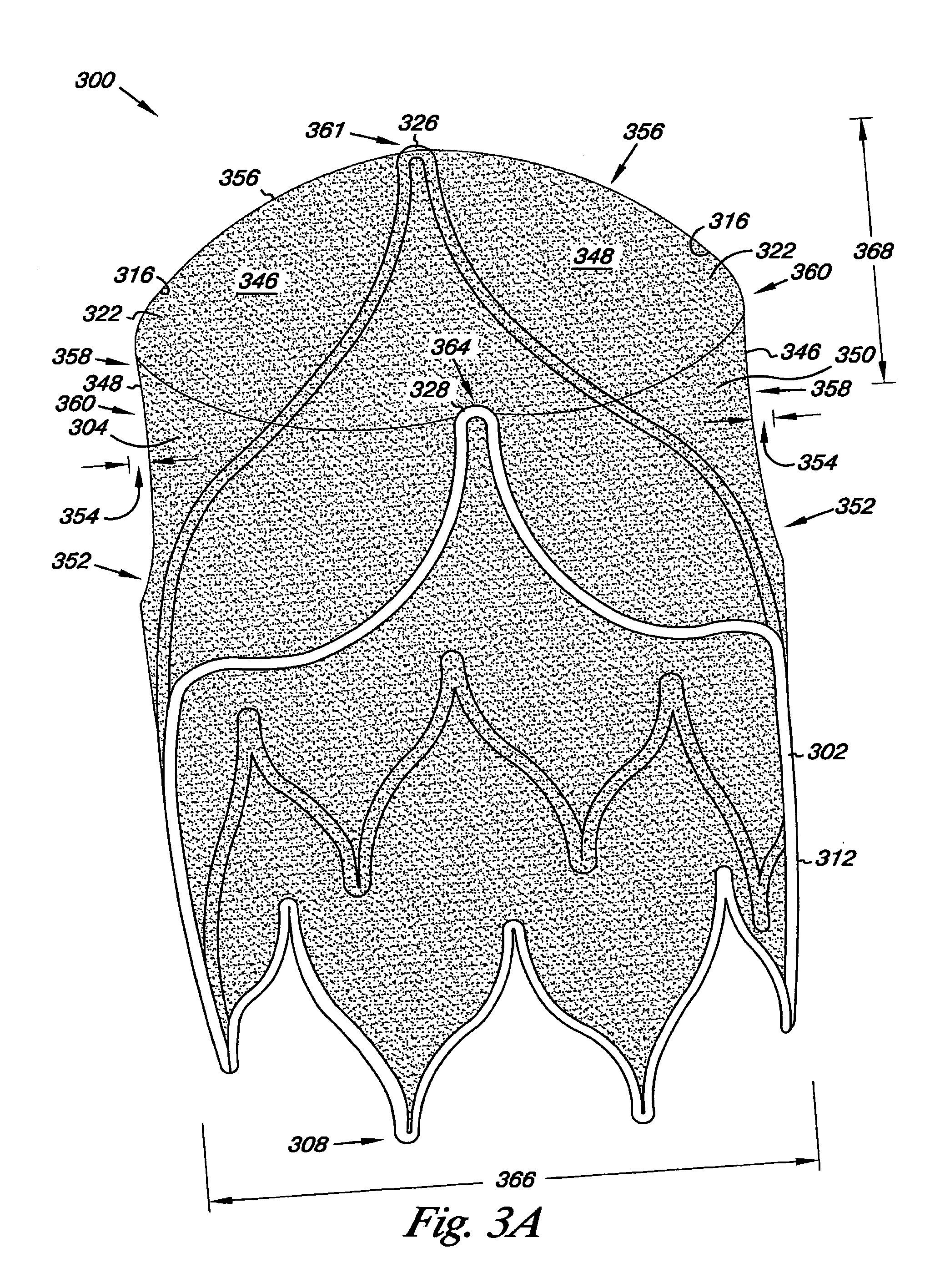
[0069] FIGS. 3A and 3B illustrate an additional embodiment of the valve 300. Valve 300 includes frame 302 having an open frame configuration and the first and second leaflet connection regions 326, 328, as described herein. The leaflet connection regions 326 and 328 also provide a first vertex 361 and a second vertex 364, respectively, relative the first end 308 of the frame 302.
[0070] As illustrated, the outer surface 312 of the frame 302 can provide a number of frame dimensions. For example, the outer surface 312 of the frame 302 can be viewed as defining a first frame dimension 366 at the first end 308 of the frame 302 and a second frame dimension 368 between the first vertex 361 and the second vertex 364 of the frame 302. In one embodiment, the second frame dimension 368 can have a larger value as compared to the first frame dimension 366. Other dimensional relationships between the first and second frame dimensions 366 and 368 are also possible.
[0071] In the present embodiment, the differences in the frame dimensions for frame 302 allow portions of the frame members 318 to provide the radial support member for the valve 300. In other words, the radial support member of the frame 302 can result from the relative shape and size of the different portions of the frame members 318. For example, as described herein the first and second frame dimensions 366, 368 can have different sizes, where the outer surface 312 of the frame 302 radially arcs from the first frame dimension 366 to the second frame dimension 368 so as to provide the radial support member of the frame 302.
[0072] So, in the present example the flaring of the of the frame member 318 from the first frame dimension 366 to the second frame dimension 368 allows the frame member 318 in the region of the first and second vertex 361 and 364 to provide the radial support member. In one embodiment, the frame members 318 can be pre and/or post treated to impart the frame dimension differences described herein. For example, frame members 318 forming the first vertex 361 and the second vertex 364 of the frame 302 could be bent to impart the radial flare. In one embodiment, a mandrel having a tapering surface could be used to impart the radial flare to the frame member 318.
[0073] The flared first and second vertex 361, 364 of the frame 302 could then be heat treated so as to fix the radial flare into the frame member 318. For example, a suitable heat treatment for a nitinol material can include heating the frame member 318 to approximately 500 degrees Celsius for approximately two (2) minutes. The frame members 318 can then be air cooled or quenched. Other material treatments (plastic deformation, forging, elastic deformation--heat setting) are also possible to impart the radial flare as described herein, many of which are material specific.
[0074] In one embodiment, the radial support member illustrated in FIG. 3 can serve to stabilize the valve 300 once positioned at a predetermined location as described herein. In addition, the configuration of the radial support member can allow the first frame dimension 366 and the second frame dimension 368 to more closely correspond to each other once the valve 300 has been positioned at the predetermined location.
[0075] The valve 300 can thither include the cover 304, where both the frame 302 and the cover 304 can resiliently radially collapse and expand, as described herein. In the present example, the cover 304 can be located over at least the outer surface 312 of the frame 302 and coupled to the first and second leaflet connection regions 326 and 328 to form the valve leaflets 322 (e.g., the first and second valve leaflets 346 and 348) and the reversibly sealable opening 316, as described herein. In an additional embodiment, the cover 304 can also be located over at least the inner surface 314 of the frame 302. A further embodiment includes the cover 304 located over at least the outer surface 312 and the inner surface 314. Anchoring elements (e.g., barbs) and radiopaque markers can also be included with valve 300, as described herein.
[0076] As described herein, the valve leaflets 322 can include the transition region 352 where the circumference of the cover 304 changes from a first circumference to a second circumference that is smaller than the first circumference. The transition region 352 also allows for the gap 354, as described herein, to be formed between the outer surface of the valve leaflets 322 and the inner wall of the vessel in which the valve 300 is implanted. The valve leaflets 322 can also include the concave pocket 360, as described herein. Cover 304 also includes the lip 356 that can have either a non-planar or a planar configuration, as described herein.
[0077] Frame member 318 of the valve frame 302 can also include a variety of cross-sectional shapes and dimensions. For example, cross-sectional shapes for the frame member 318 can be as described herein. In addition, the frame member 318 can have two or more cross-sectional shapes, two or more different dimensions (e.g., a greater width and depth of the frame member 318 for the first and second vertices 361 and 364 as compared to the remainder of the frame member 318).
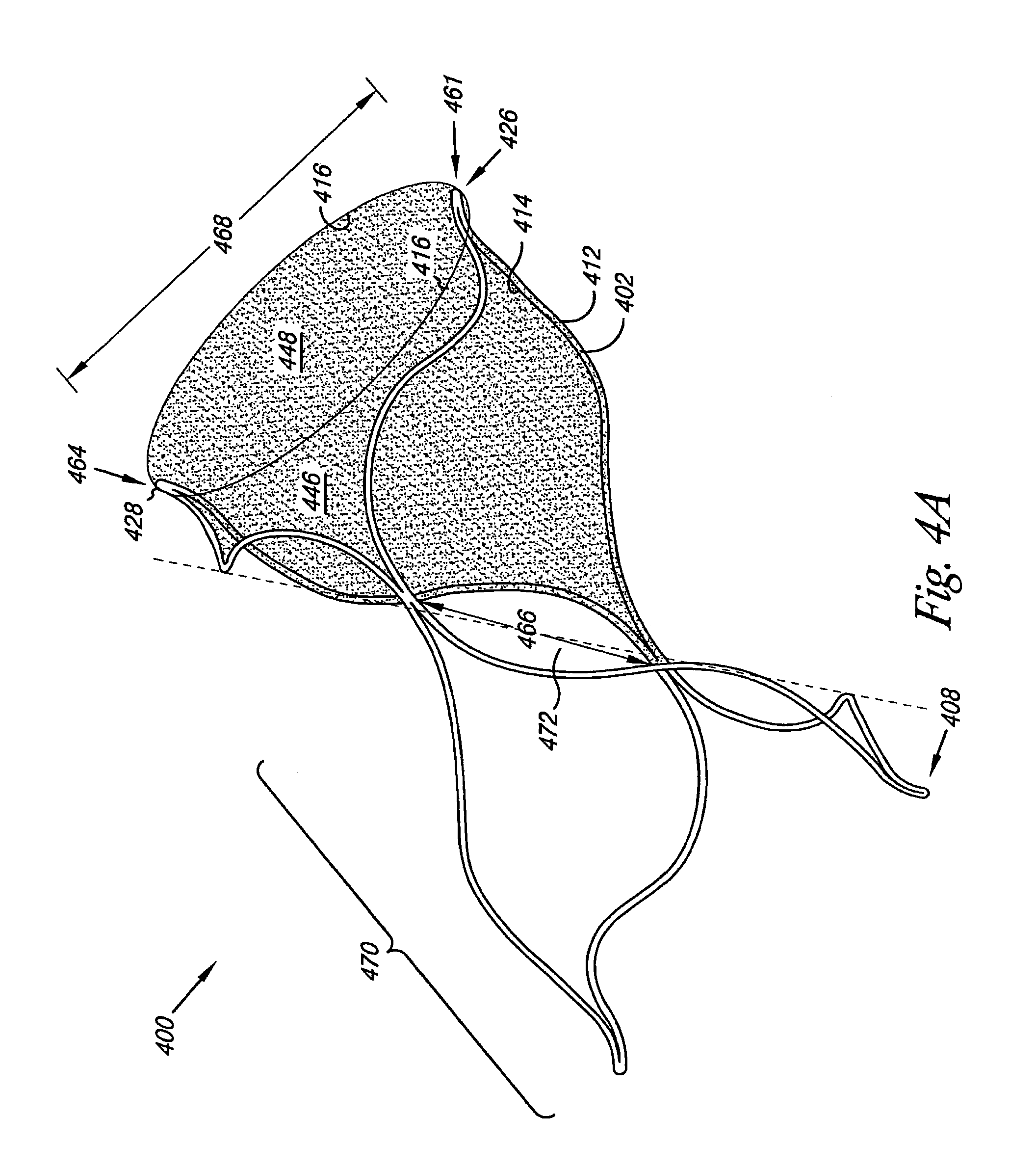
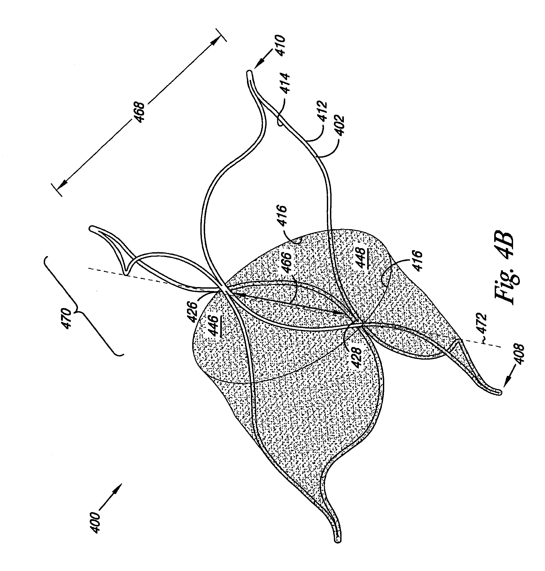
[0078] FIGS. 4A and 4B illustrate additional embodiments of the valve 400. As illustrated, the frame 402 includes an open frame configuration and the first leaflet connection region 426 and the second leaflet connection region 428, as described herein. FIGS. 4A and 4B illustrate embodiments in which the cover 404 can be positioned at different locations along the frame 402 so as to form the valve leaflets 422. For example, in FIG. 4A the leaflet connection regions 426 and 428 are located at the first vertex 461 and the second vertex 464, respectively, relative the first end 408 of the frame 402. In an additional example, FIG. 4B provides an illustration in which the leaflet connection regions 426 and 428 are positioned between the end of the frame 402 having the first vertex 461 and the second vertex 464 and the first end 408 of the frame 402.
[0079] The frame 402 can include multiple structural configurations. For example, the frame 402 can include a support frame region 470 that helps to stabilize and position the valve 400 inside a vessel. In one embodiment, FIGS. 4A and 4B provide an illustration in which the support frame region 470 extends from an axis 472 through a mid-point of the frame 402 away from the leaflet connection regions 426 and 428.
[0080] As illustrated, the outer surface 412 of the frame 402 can also provide a number of frame dimensions. For example, the outer surface 412 of the frame 402 can be viewed as defining the first frame dimension 466 at the axis 472 of the frame 402 and a second frame dimension 468 measure at either the first or second end 408, 410 of the frame 402. In one embodiment, the second frame dimension 468 can have a larger value as compared to the first frame dimension 466. Other dimensional relationships between the first and second frame dimensions 466 and 468 are also possible.
[0081] In the present embodiment, the differences in the frame 402 dimensions provide radial support members for the valve 400. In other words, radial support members of the frame 402 result from the relative shape and size of the different portions of the frame members 418. For example, as described herein the first and second frame dimensions 466, 468 can have different sizes, where the outer surface 412 of the frame 402 radially arcs from the first frame dimension 466 to the second frame dimension 468 so as to provide the radial support member of the frame 402. So, in the present example the flaring of the of the frame member 418 from the first frame dimension 466 to the second frame dimension 468 allows the frame member 418 in the region of the first and second vertex 461 and 464 to provide the radial support member.
[0082] In one embodiment, the radial support members illustrated in FIGS. 4A and 4B can serve to stabilize the valve 400 once positioned at a predetermined location as described herein. In addition, the configuration of the radial support member can allow the first frame dimension 466 and the second frame dimension 468 to more closely correspond to each other once the valve 400 has been positioned at the predetermined location.
[0083] The valve 400 can further include the cover 404, where both the frame 402 and the cover 404 can resiliently radially collapse and expand, as described herein. In the present example, the cover 404 can be located over at least the inner surface 414 of the frame 402 and coupled to the first and second leaflet connection regions 426 and 428 to form the valve leaflets 422 (e.g., the first and second valve leaflets 446 and 448) and the reversibly sealable opening 416, as described herein. In an additional embodiment, the cover 404 can also be located over at least the outer surface 412 of the frame 402. A further embodiment includes the cover 404 located over at least the outer surface 412 and the inner surface 414. Anchoring elements (e.g., barbs) and radiopaque markers can also be included with valve 400, as described herein.
[0084] Frame member 418 of the valve frame 402 can also include a variety of cross-sectional shapes and dimensions. For example, cross-sectional shapes for the frame member 418 can be as described herein. In addition, the frame member 418 can have two or more cross-sectional shapes, two or more different dimensions (e.g., a greater width and depth of the frame member 418 for one or more of the first and second vertices 461, 464 as compared to the remainder of the frame member 418).
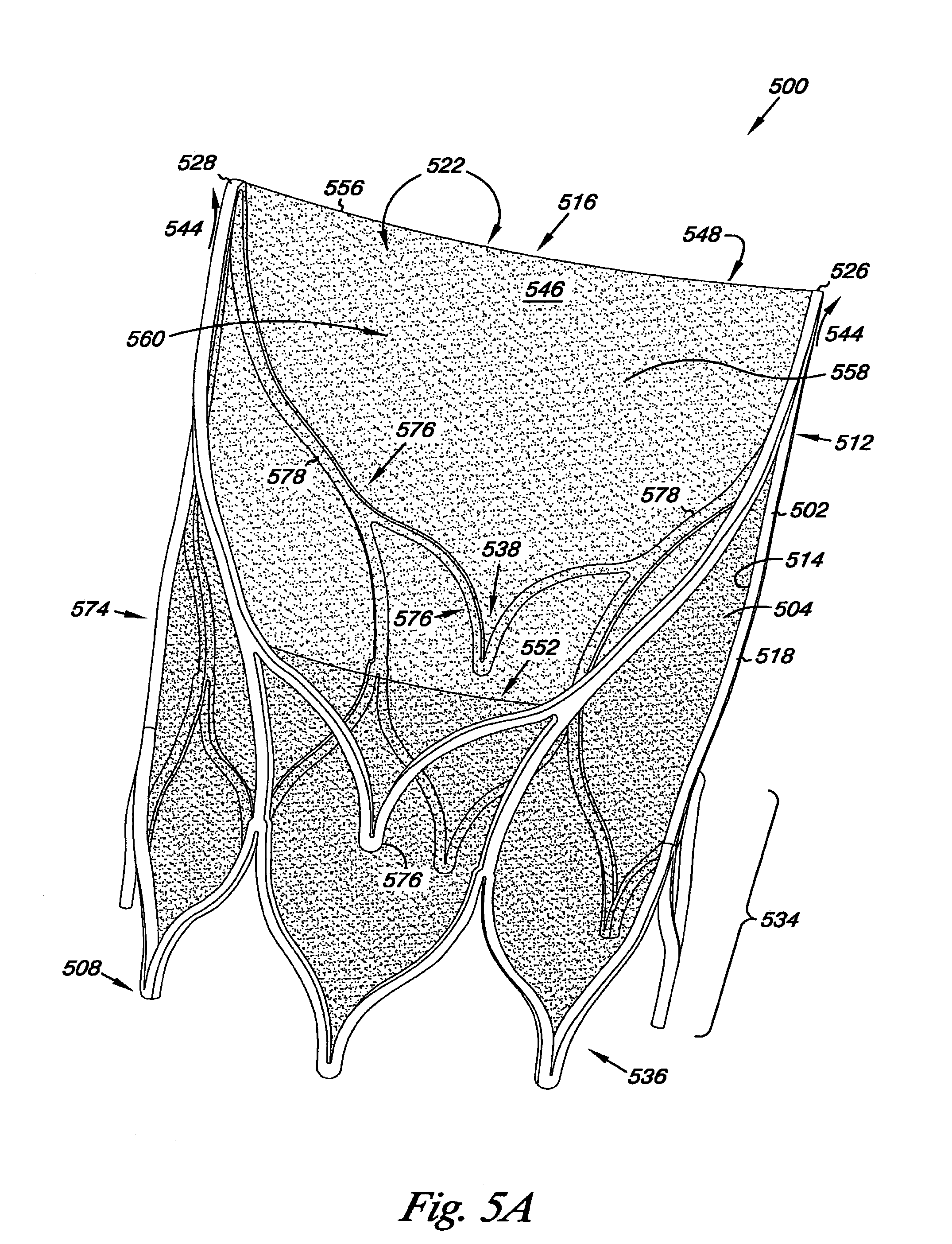
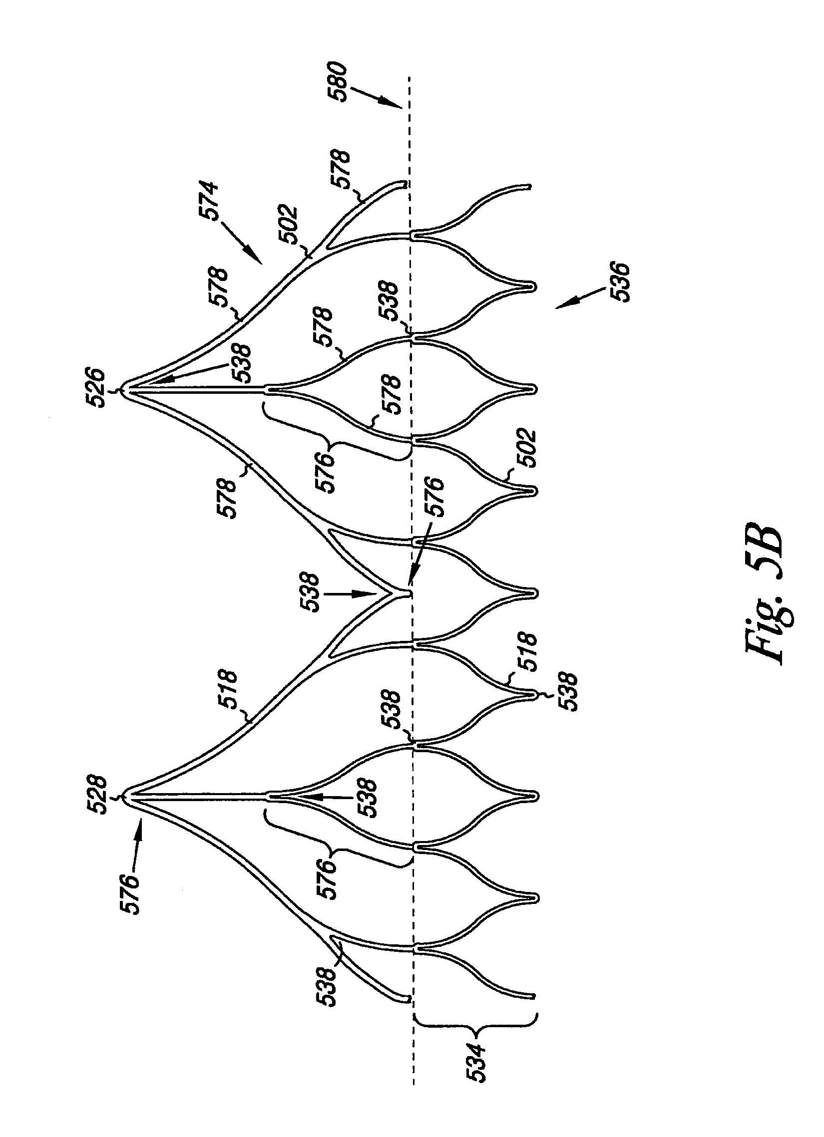
[0085] FIGS. 5A and 5B illustrate an additional embodiment of the valve 500. Valve 500 includes the cover 504 as described herein. The frame 502 of the valve 500 further includes a triple wishbone configuration 574. In one embodiment, the triple wishbone configuration 574 of the frame 502 includes a series of interconnected bifurcated members having connection points that act as spring members, as will be described herein. In one embodiment, the interconnection of these members allows for the spring force of aligned springs integrated into the frame 502 to be added in series so as to increase the spring force potential of the frame 502.
[0086] FIG. 5B provides an illustration of the triple wishbone configuration 574 for the frame 502 that has been cut to provide it in a planar view. In one embodiment, the frame member 518 in the triple wishbone configuration 574 includes a radial support member 534. As illustrated, the radial support member 534 can be in the form of a tubular ring 536 that can move radially as the valve 500 radially collapses and expands.
[0087] In one embodiment, the tubular ring 536 can provide a spring force (e.g., elastic potential energy) to counter radial compression of the frame 502 towards its uncompressed state. For example, the tubular ring 536 has a zig-zag configuration that includes corners 538 that can develop the spring force when the frame 502 is under compressed. As will be appreciated, the corners 538 can have a number of configurations, including turns defining angles and/or arcs (e.g., having a radius of curvature).
[0088] The frame 502 further includes spring members 576 interconnected with the radial support member 534. As illustrated, the spring members 576 are associated with the radial support member 534 adjacent the corners 538. For example, the spring members 576 can include extensions 578 that join the radial support member 534 adjacent the corners 538 along a common plane 580. In the present embodiment, extensions 578 join the radial support member 534 adjacent each corner 538 along the plane 580.
[0089] The spring members 576 also include corners 538 that can develop the spring force when the frame 502 is under compressed. As will be appreciated, the corners 538 can have a number of configurations, including turns defining angles and/or arcs (e.g., having a radius of curvature). In one embodiment, the corners 538 of the spring members 576 also provide the first and second leaflet connection regions 526, 528. In one embodiment, the spring members 576 interconnected with the radial support member 534 helps to stabilize the relative positions of the connection regions 526 and 528 (e.g., limit relative fluctuations of the connection regions 526 and 528).
[0090] The frame 502 can further include dimensional relationships, as described herein, which allow the frame 502 to flare radially outward relative the first end 508 of the frame. The valve 500 can further include the cover 504, where both the frame 502 and the cover 504 can resiliently radially collapse and expand, as described herein. In the present example, the cover 504 can be located over at least the inner surface 514 of the frame 502 and coupled to the first and second leaflet connection regions 526 and 528 to form the valve leaflets 522 (e.g., the first and second valve leaflets 546 and 548) and the reversibly sealable opening 516, as described herein.
[0091] The valve leaflets 522 can further include the transition region 552 where the circumference of the cover 504 changes from a first circumference to a second circumference that is smaller than the first circumference. The transition region 552 also allows for the gap, as described herein, to be formed between the outer surface of the valve leaflets 522 and the inner wall of the vessel in which the valve 500 is implanted. The valve leaflets 522 can also include the concave pocket 560, as described herein. Cover 504 also includes the lip 556 that can have either a non-planar or a planar configuration, as described herein.
[0092] Frame member 518 of the valve frame 502 can also include a variety of cross-sectional shapes and dimensions. For example, cross-sectional shapes for the frame member 518 can be as described herein. In addition, the frame member 518 can have two or more cross-sectional shapes, two or more different dimensions (e.g., a greater width and depth of the frame member 518 for the corners 538 as compared to the remainder of the frame member 518).
[0093] FIG. 6 illustrates one embodiment of a system 680. System 680 includes valve 600, as described herein, reversibly joined to catheter 682. The catheter 682 includes an elongate body 684 having a proximal end 686 and a distal end 688, where valve 600 can be located between the proximal end 686 and distal end 688. The catheter 682 can further include a lumen 690 longitudinally extending to the distal end 688. In one embodiment, lumen 690 extends between proximal end 686 and distal end 688 of catheter 682. The catheter 682 can further include a guidewire lumen 692 that extends within the elongate body 684, where the guidewire lumen 692 can receive a guidewire for positioning the catheter 682 and the valve 600 within a body lumen (e.g., a vein of a patient).
[0094] The system 680 can further include a deployment shaft 694 positioned within lumen 690, and a sheath 696 positioned adjacent the distal end 688. In one embodiment, the valve 600 can be positioned at least partially within the sheath 696 and adjacent the deployment shaft 694. The deployment shaft 694 can be moved within the lumen 690 to deploy valve 600. For example, deployment shaft 694 can be used to push valve 600 from sheath 696 in deploying valve 600.
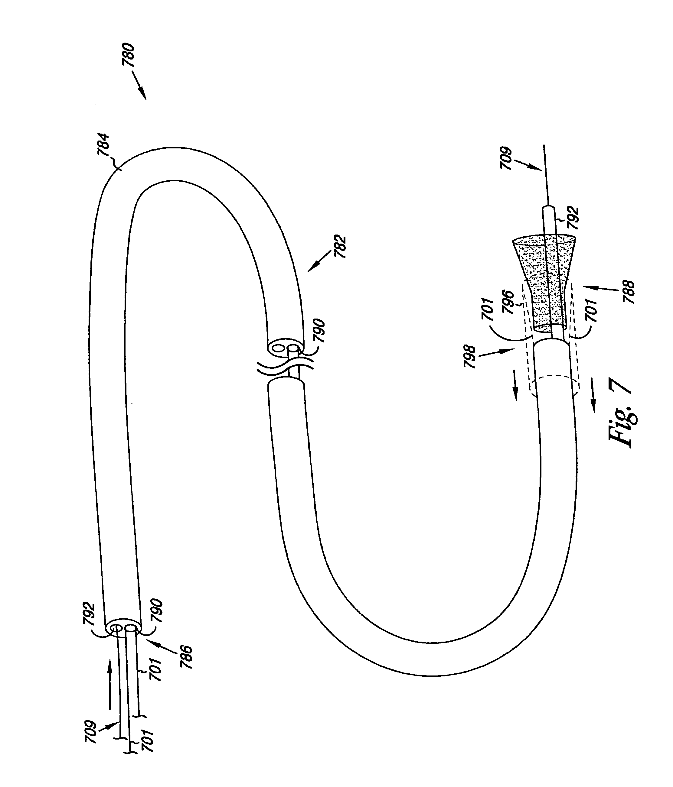
[0095] FIG. 7 illustrates an additional embodiment of the system 780. The catheter 782 includes elongate body 784, lumen 790, a retraction system 798 and a retractable sheath 796. The retractable sheath 796 can be positioned over at least a portion of the elongate body 784, where the retractable sheath 796 can move longitudinally along the elongate body 784. The valve 700 can be positioned at least partially within the retractable sheath 796, where the retractable sheath 796 moves along the elongate body 796 to deploy the valve 700.
[0096] In one embodiment, retraction system 798 includes one or more wires 701 coupled to the retractable sheath 796, where the wires are positioned at least partially within and extend through lumen 790 in the elongate body 784. Wires of the retraction system 798 can then be used to retract the retractable sheath 796 in deploying valve 700. In one embodiment, a portion of the elongate body 784 that defines the guidewire lumen 792 extends through the lumen 706 of the valve 700 to protect the valve 700 from the movement of the guidewire 709.
[0097] FIG. 8 illustrates an additional embodiment of the system 880. The catheter 882 includes elongate body 884, an inflatable balloon 803 positioned adjacent the distal end 888. The elongate body 884 further includes an inflation lumen 805 longitudinally extending in the elongate body 884 of the catheter 882 from the inflatable balloon 803 to the proximal end 886. In one embodiment, an inflation pump 807 can be releasably coupled to the inflation lumen 805 and used to inflate and deflate the balloon 803.
[0098] In the present example, the inflatable balloon 803 can be at least partially positioned within the lumen 806 of the valve 800. The inflatable balloon 803 can be inflated through the lumen 805 with the inflation pump 807 to deploy the valve 800. The system 880 can further include the guidewire lumen 892 to receive a guidewire 809.
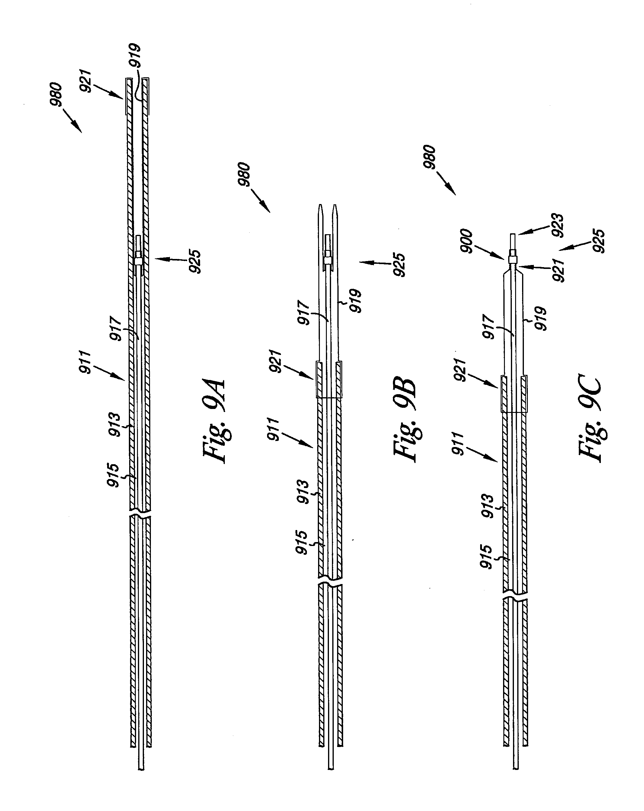
[0099] FIGS. 9A-9C illustrate an additional embodiment of the system 980. The system 980 includes a tubular sheath 911 having an elongate body 913 and a lumen 915. The system 980 further includes a delivery shaft 917 positioned within the lumen 915 of the tubular sheath 911. In one embodiment, the tubular sheath 911 and the delivery shaft 917 can move longitudinally relative each other.
[0100] System 980 also includes a flexible cover 919 between the tubular sheath 911 and the delivery shaft 917. In one embodiment, the flexible cover 919 is connected to the tubular sheath 911 and the delivery shaft 917 at a fluid tight seal 921 so as to prevent fluid from outside the system 980 entering the lumen 915. As illustrated, the valve 900 can be positioned over the delivery shaft 915 and the flexible cover 919 adjacent a distal end 923 of the delivery shaft 917.
[0101] In one embodiment, the tubular sheath 911, the delivery shaft 917 and the flexible cover 919 can each be formed from a number of different materials. For the tubular sheath examples include, but are not limited to materials selected from one or more of ePTFE, PTFE, PE, PET, silicone, and polyurethanes. For the delivery shaft 917 examples include, but are not limited to, those selected from a metal, a metal alloy, and/or a polymer. Examples include, but are not limited one or more of ePTFE, PTFE, PE, nylons, PET, silicone, polyurethanes, and stainless steel (e.g., 316L).
[0102] In addition, the delivery shaft 917 can also include a configuration that imparts sufficient column rigidity to allow it to be pushed and/or pulled through the lumen 915. For example, the delivery shaft 917 can be formed with reinforcing members bound within the body of the delivery shaft 917 (e.g., an elongate braid of stainless steel co-extruded with a polymer). For the flexible cover 919 examples include, but are not limited to, materials selected from one or more of ePTFE, PTFE, PE, PET, nylons, and polyurethanes. As will be appreciated, other materials and configurations for forming the tubular sheath 911, the delivery shaft 917 and the flexible cover 919 are also possible.
[0103] As illustrated in FIGS. 9A-9C, the valve 900 can be held in the same relative location 925 as it is being deployed. As illustrated in FIG. 9A, the valve 900, a portion of the flexible cover 919 and the delivery shaft 917 can be positioned within the lumen 915 of the tubular sheath 911. In one embodiment, the configuration illustrated in FIG. 9A allows the valve 900 to be delivered in its compressed state to a predetermined location in the lumen of the body. Once at the predetermined location, the sheath 911 can then be moved relative the delivery shaft 917. FIG. 9B illustrates a situation where the sheath 911 has been pulled over the valve 900 location 925 and at least partially over the delivery shaft 917.
[0104] As illustrated, the flexible cover 919 has a tubular configuration that folds back inside of itself (i.e., its lumen) as the tubular sheath 911 is drawn over the valve 900 and the delivery shaft 917. In one embodiment, the lumen 915 of the sheath 911 can contain a lubricating fluid (e.g., saline) to allow the flexible cover 919 to more easily pass over itself as illustrated. As the tubular sheath 911 continues to be pulled back relative the delivery shaft 917 until the valve 900 is released, as illustrated in FIG. 9C. In one embodiment, the valve 900 can include a self-expanding frame that allows the valve 900 to deploy at location 925 once released.
[0105] The embodiments of the present invention further include methods for forming the valve of the present invention, as described herein. For example, the method of forming the valve can include forming the frame having the leaflet connection regions, as described. The method can include providing the radial support member, or members, on the frame for the leaflet connection regions. As described herein, the radial support member can include the tubular rings and/or the radial flares imparted into the leaflet connection regions. The method also includes providing the cover on the frame, where connecting the cover to the leaflet connection regions provides at least the first leaflet and the second leaflet of the valve having surfaces defining the reversibly sealable opening for unidirectional flow of a liquid through the valve.
[0106] In an additional example, the valve can be reversibly joined to the catheter, which can include a process of altering the shape of the valve from a first shape, for example an expanded state, to the compressed state, as described herein. For example, the valve can be reversibly joined with the catheter by positioning valve in the compressed state at least partially within the sheath of the catheter. In one embodiment, positioning the valve at least partially within the sheath of the catheter includes positioning the valve in the compressed state adjacent the deployment shaft of the catheter. In an another embodiment, the sheath of the catheter functions as a retractable sheath, where the valve in the compressed state can be reversibly joined with the catheter by positioning the valve at least partially within the reversible sheath of the catheter. In a further embodiment, the catheter can include an inflatable balloon, where the balloon can be positioned at least partially within the lumen of the valve, for example, in its compressed state.
[0107] The embodiments of the valve described herein may be used to replace, supplement, or augment valve structures within one or more lumens of the body. For example, embodiments of the present invention may be used to replace an incompetent venous valve and help to decrease backflow of blood in the venous system of the legs.
[0108] In one embodiment, the method of replacing, supplementing, and/or augmenting a valve structure can include positioning at least part of the catheter including the valve at a predetermined location within the lumen of a body. For example, the predetermined location can include a position within a body lumen of a venous system of a patient, such as a vein of a leg.
[0109] In one embodiment, positioning the catheter that includes the valve within the body lumen of a venous system includes introducing the catheter into the venous system of the patient using minimally invasive percutaneous, transluminal catheter based delivery system, as is known in the art. For example, a guidewire can be positioned within a body lumen of a patient that includes the predetermined location. The catheter, including valve, as described herein, can be positioned over the guidewire and the catheter advanced so as to position the valve at or adjacent the predetermined location.
[0110] As described herein, the position of the one or more radiopaque markers can be selected so as to provide information on the position, location and orientation (e.g., axial, directional, and/or clocking position) of the valve during its implantation. For example, radiopaque markers can be configured radially and longitudinally on predetermined portions of the valve frame and/or the elongate body of the catheter to indicate not only a longitudinal position, but also a radial position of the valve leaflets and the valve frame (referred to as a clock position). In one embodiment, the radiopaque markers are configures to provide radiographic images that indicate the relative radial position of the valve and valve leaflets on the catheter.
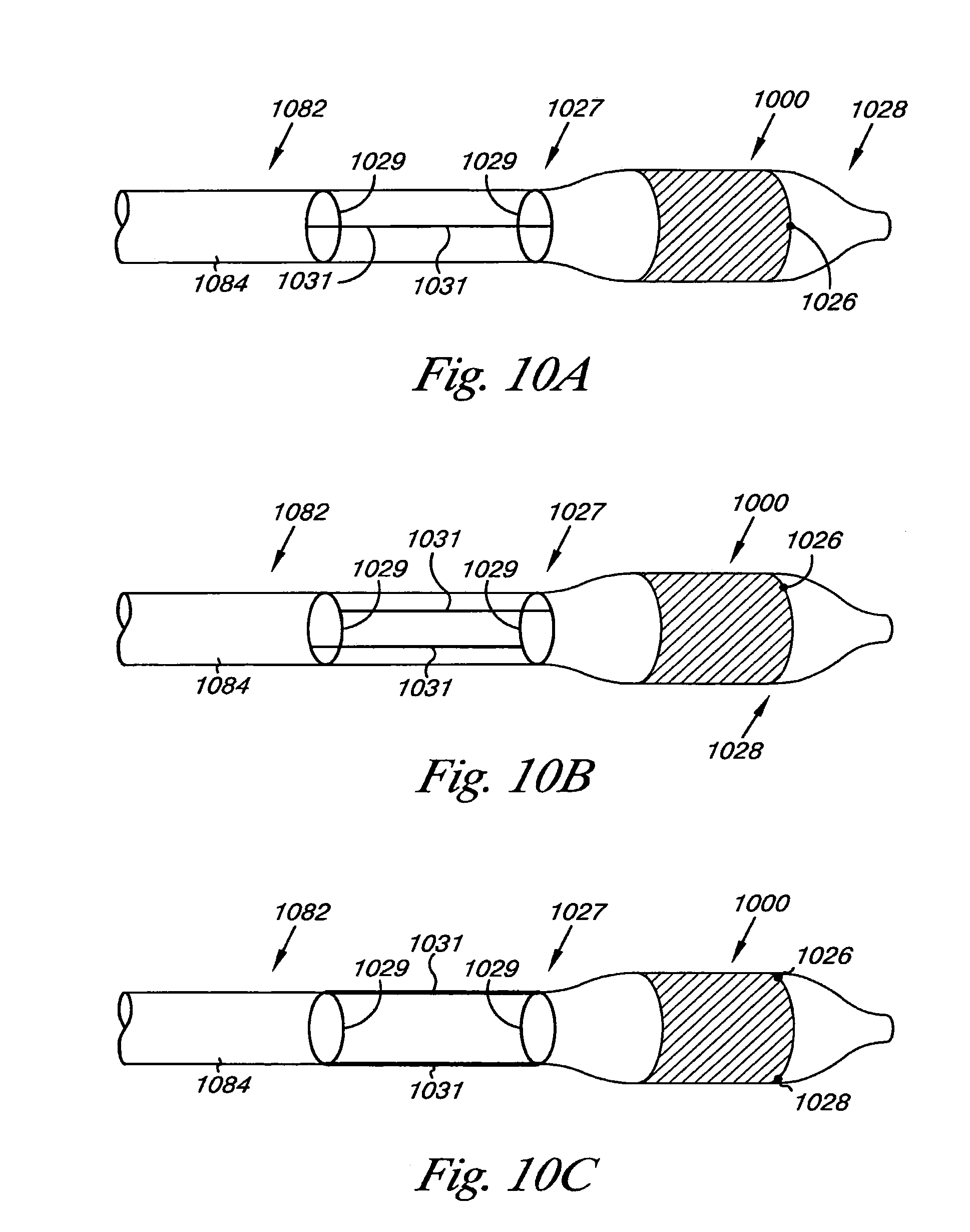
[0111] FIGS. 10A-10C provide an illustration of the radiopaque markers 1027 associated with the elongate body 1084 of the catheter 1082. As illustrated, the radiopaque markers 1027 include a radial component 1029 and a longitudinal component 1031. Depending upon the radial position of the catheter 1082, the radiopaque markers 1027 can provide a different and distinguishable radiographic image. For example, in a first position 1033 illustrated in FIG. 10A the longitudinal component 1031 of the radiopaque markers 1027 are aligned so as to overlap. As the catheter 1082 is rotated, as illustrated in FIGS. 10B and 10C, the radiographic image of the radial component 1029 and/or longitudinal component 1031 of the radiopaque markers 1027 change.
[0112] The change in the relationship of the radial and longitudinal components 1029, 1031 as the catheter 1082 is rotated allows for the relative position of the valve, valve frame and valve leaflets to be determined from the radiographic image. For example, the relative position of the first and second leaflet connection regions 1026, 1028 could be aligned with longitudinal component 1031 of the radiopaque markers 1027. This would allow the clock position for the valve 1000 to be determined so that the valve can be positioned in a more natural orientation relative the compressive forces the valve will experience in situ. In other words, the allowing for clocking of the valve 1000 as described herein allows the valve to be radially positioned in same orientation as native valve that it's replacing and/or augmenting.
[0113] As will be appreciated, other relative relationships between the radiopaque markers 1027 and the position of the valve 1000 on the catheter 1082 are possible. So, embodiments of the present invention should not be limited to the present example. For example, additional radiopaque markers 1027 on the valve 1000 could be used either alone or in combination with radiopaque markers 1027 on the catheter 1082 to help in positioning the valve 1000 within a lumen.
[0114] The valve can be deployed from the catheter at the predetermined location in a number of ways, as described herein. In one embodiment, valve of the present invention can be deployed and placed in a number of vascular locations. For example, valve can be deployed and placed within a major vein of a patient's leg. In one embodiment, major veins include, but are not limited to, those of the peripheral venous system. Examples of veins in the peripheral venous system include, but are not limited to, the superficial veins such as the short saphenous vein and the greater saphenous vein, and the veins of the deep venous system, such as the popliteal vein and the femoral vein.
[0115] As described herein, the valve can be deployed from the catheter in a number of ways. For example, the catheter can include the retractable sheath in which valve can be at least partially housed, as described herein. Valve can be deployed by retracting the retractable sheath of the catheter, where the valve self-expands to be positioned at the predetermined location. In an additional example, the catheter can include a deployment shaft and sheath in which valve can be at least partially housed adjacent the deployment shaft, as described herein. Valve can be deployed by moving the deployment shaft through the catheter to deploy valve from the sheath, where the valve self-expands to be positioned at the predetermined location. In an additional embodiment, the valve can be deployed through the use of an inflatable balloon.
[0116] Once implanted, the valve can provide sufficient contact and expansion force against the body lumen wall to prevent retrograde flow between the valve and the body lumen wall. For example, the valve can be selected to have a larger expansion diameter than the diameter of the inner wall of the body lumen. This can then allow valve to exert a force on the body lumen wall and accommodate changes in the body lumen diameter, while maintaining the proper placement of valve. As described herein, the valve can engage the lumen so as to reduce the volume of retrograde flow through and around valve. It is, however, understood that some leaking or fluid flow may occur between the valve and the body lumen and/or through valve leaflets.
[0117] In addition, the use of both the radial support member and/or the support frame region of the valve can provide a self centering aspect to valve within a body lumen. In one embodiment, the self centering aspect resulting from the radial support member and/or the support frame region may allow valve to maintain a substantially coaxial alignment with the body lumen (e.g., such as a vein) as valve leaflets deflect between the open and closed configurations so as to better seal the reversible opening when valve is closed.
[0118] While the present invention has been shown and described in detail above, it will be clear to the person skilled in the art that changes and modifications may be made without departing from the scope of the invention. As such, that which is set forth in the foregoing description and accompanying drawings is offered by way of illustration only and not as a limitation. The actual scope of the invention is intended to be defined by the following claims, along with the full range of equivalents to which such claims are entitled.
[0119] In addition, one of ordinary skill in the art will appreciate upon reading and understanding this disclosure that other variations for the invention described herein can be included within the scope of the present invention. For example, the frame 102 and/or the cover 104 can be coated with a non-thrombogenic biocompatible material, as are known or will be known.
[0120] In the foregoing Detailed Description, various features are grouped together in several embodiments for the purpose of streamlining the disclosure. This method of disclosure is not to be interpreted as reflecting an intention that the embodiments of the invention require more features than are expressly recited in each claim. Rather, as the following claims reflect, inventive subject matter lies in less than all features of a single disclosed embodiment. Thus, the following claims are hereby incorporated into the Detailed Description, with each claim standing on its own as a separate embodiment.
* * * * *
D00000
D00001
D00002
D00003
D00004
D00005
D00006
D00007
D00008
D00009
D00010
D00011
D00012
D00013
D00014
D00015
D00016

D00017
D00018
XML
uspto.report is an independent third-party trademark research tool that is not affiliated, endorsed, or sponsored by the United States Patent and Trademark Office (USPTO) or any other governmental organization. The information provided by uspto.report is based on publicly available data at the time of writing and is intended for informational purposes only.
While we strive to provide accurate and up-to-date information, we do not guarantee the accuracy, completeness, reliability, or suitability of the information displayed on this site. The use of this site is at your own risk. Any reliance you place on such information is therefore strictly at your own risk.
All official trademark data, including owner information, should be verified by visiting the official USPTO website at www.uspto.gov. This site is not intended to replace professional legal advice and should not be used as a substitute for consulting with a legal professional who is knowledgeable about trademark law.