Systems and methods for mitigating heat rejection limitations of a thermoelectric module
Edwards , et al. Oc
U.S. patent number 10,458,683 [Application Number 14/849,232] was granted by the patent office on 2019-10-29 for systems and methods for mitigating heat rejection limitations of a thermoelectric module. This patent grant is currently assigned to Phononic, Inc.. The grantee listed for this patent is Phononic, Inc.. Invention is credited to Daniel Barus, Jesse W. Edwards, Marshall Stanley, Daniel Swann, Robert Joseph Therrien, Abhishek Yadav.


| United States Patent | 10,458,683 |
| Edwards , et al. | October 29, 2019 |
Systems and methods for mitigating heat rejection limitations of a thermoelectric module
Abstract
Systems and methods for mitigating heat rejection limitations of a thermoelectric module are disclosed. In some embodiments, a method of operating a thermoelectric module includes providing a first amount of power to the thermoelectric module and determining that a temperature of a hot side of the thermoelectric module is above a first threshold. The method also includes, in response to determining that the temperature of the hot side is above the first threshold, providing a second amount of power to the thermoelectric module that is less than the first amount of power. The method also includes determining that the temperature of the hot side of the thermoelectric module is below a second threshold and providing a third amount of power to the thermoelectric module. In some embodiments, this mitigates heat rejection limitations of the thermoelectric module, especially when the hot side of the thermoelectric module is passively cooled.
| Inventors: | Edwards; Jesse W. (Wake Forest, NC), Therrien; Robert Joseph (Cary, NC), Barus; Daniel (Raleigh, NC), Stanley; Marshall (Chapel Hill, NC), Yadav; Abhishek (Cary, NC), Swann; Daniel (Cockeysville, MD) | ||||||||||
|---|---|---|---|---|---|---|---|---|---|---|---|
| Applicant: |
|
||||||||||
| Assignee: | Phononic, Inc. (Durham,
NC) |
||||||||||
| Family ID: | 55074302 | ||||||||||
| Appl. No.: | 14/849,232 | ||||||||||
| Filed: | September 9, 2015 |
Prior Publication Data
| Document Identifier | Publication Date | |
|---|---|---|
| US 20160018141 A1 | Jan 21, 2016 | |
Related U.S. Patent Documents
| Application Number | Filing Date | Patent Number | Issue Date | ||
|---|---|---|---|---|---|
| PCT/US2015/041383 | Jul 21, 2015 | ||||
| 62027080 | Jul 21, 2014 | ||||
| 62027083 | Jul 21, 2014 | ||||
| Current U.S. Class: | 1/1 |
| Current CPC Class: | F25B 21/04 (20130101); H01L 35/02 (20130101); F25B 2321/0212 (20130101) |
| Current International Class: | F25B 21/04 (20060101); H01L 35/02 (20060101) |
References Cited [Referenced By]
U.S. Patent Documents
| 2027057 | January 1936 | Munters |
| 2938357 | May 1960 | Sheckler |
| 2947150 | August 1960 | Roeder, Jr. |
| 3100969 | August 1963 | Elfving |
| 3191391 | June 1965 | Muller |
| 3196620 | July 1965 | Elfving et al. |
| 3393127 | July 1968 | Detman et al. |
| 3532159 | October 1970 | Hammitt et al. |
| 3621906 | November 1971 | Leffert |
| 3821881 | July 1974 | Harkias |
| 4011104 | March 1977 | Basiulis |
| 4213448 | July 1980 | Hebert |
| 4278906 | July 1981 | Kullmann |
| 4306613 | December 1981 | Christopher |
| 4335578 | June 1982 | Osborn et al. |
| 4357932 | November 1982 | Stacy |
| 4366857 | January 1983 | Mayer |
| 4382466 | May 1983 | Shiraishi |
| 4383414 | May 1983 | Beitner |
| 4393663 | July 1983 | Grunes et al. |
| 4449377 | May 1984 | Draper |
| 4474228 | October 1984 | Rogalski et al. |
| 4476922 | October 1984 | Heilig, Jr. et al. |
| 4498306 | February 1985 | Tyree, Jr. |
| 4505261 | March 1985 | Hunter |
| 4513732 | April 1985 | Feldman, Jr. |
| 4545364 | October 1985 | Maloney |
| 4546608 | October 1985 | Shiina et al. |
| 4607498 | August 1986 | Dinh |
| 4687048 | August 1987 | Edelstein et al. |
| 4700771 | October 1987 | Bennett et al. |
| 4796439 | January 1989 | Yamada et al. |
| 4810460 | March 1989 | Gluntz |
| 4833567 | May 1989 | Saaski et al. |
| 4842050 | June 1989 | Harper |
| 4848445 | July 1989 | Harper |
| 5000252 | March 1991 | Faghri |
| 5069274 | December 1991 | Haslett et al. |
| 5161090 | November 1992 | Crawford et al. |
| 5190098 | March 1993 | Long |
| 5195575 | March 1993 | Wylie |
| 5309725 | May 1994 | Cayce |
| 5333677 | August 1994 | Molivadas |
| 5355678 | October 1994 | Beitner |
| 5384051 | January 1995 | McGinness |
| 5385203 | January 1995 | Mitsuhashi et al. |
| 5386701 | February 1995 | Cao |
| 5400607 | March 1995 | Cayce |
| 5406805 | April 1995 | Radermacher et al. |
| 5408847 | April 1995 | Erickson |
| 5409547 | April 1995 | Watanabe et al. |
| 5411077 | May 1995 | Tousignant |
| 5456081 | October 1995 | Chrysler et al. |
| 5458189 | October 1995 | Larson et al. |
| 5477706 | December 1995 | Kirol et al. |
| 5551244 | September 1996 | Bailey |
| 5558783 | September 1996 | McGuinness |
| 5579830 | December 1996 | Giammaruti |
| 5587880 | December 1996 | Phillips et al. |
| 5596981 | January 1997 | Soucy |
| 5598721 | February 1997 | Rockenfeller et al. |
| 5622057 | April 1997 | Bussjager et al. |
| 5628205 | May 1997 | Rockenfeller et al. |
| 5647429 | July 1997 | Oktay et al. |
| 5655598 | August 1997 | Garriss et al. |
| 5695007 | December 1997 | Fauconnier et al. |
| 5704416 | January 1998 | Larson et al. |
| 5737840 | April 1998 | Akachi |
| 5737923 | April 1998 | Gilley et al. |
| 5770903 | June 1998 | Bland et al. |
| 5864466 | January 1999 | Remsburg |
| 5867990 | February 1999 | Ghoshal |
| 5890371 | April 1999 | Rajasubramanian et al. |
| 5931001 | August 1999 | Watanabe et al. |
| 5931156 | August 1999 | Wang et al. |
| 5966939 | October 1999 | Tauchi |
| 5970719 | October 1999 | Merritt |
| 6003319 | December 1999 | Gilley et al. |
| 6006998 | December 1999 | Rerolle |
| 6014968 | January 2000 | Teoh |
| 6019165 | February 2000 | Batchelder |
| 6021844 | February 2000 | Batchelder |
| 6055157 | April 2000 | Bartilson |
| RE36684 | May 2000 | Rockenfeller et al. |
| 6064572 | May 2000 | Remsburg |
| 6073888 | June 2000 | Gelon et al. |
| 6097597 | August 2000 | Kobayashi |
| 6109044 | August 2000 | Porter et al. |
| 6148905 | November 2000 | Sehmbey |
| 6158502 | December 2000 | Thomas |
| 6161388 | December 2000 | Ghoshal |
| 6167948 | January 2001 | Thomas |
| 6173576 | January 2001 | Ishida et al. |
| 6192979 | February 2001 | Koch et al. |
| 6234242 | May 2001 | Sehmbey et al. |
| 6237223 | May 2001 | McCullough |
| 6237682 | May 2001 | Bowers et al. |
| 6294853 | September 2001 | Lin et al. |
| 6314741 | November 2001 | Hiraishi |
| 6345507 | February 2002 | Gillen |
| 6347521 | February 2002 | Kadotani et al. |
| 6360813 | March 2002 | Katoh et al. |
| 6382309 | May 2002 | Kroliczek et al. |
| 6388882 | May 2002 | Hoover et al. |
| 6410982 | June 2002 | Brownell et al. |
| 6418729 | July 2002 | Dominguez-Alonso et al. |
| 6463743 | October 2002 | Lalibertee |
| 6499777 | December 2002 | Wang |
| 6527548 | March 2003 | Kushch et al. |
| 6533029 | March 2003 | Phillips |
| 6536510 | March 2003 | Khrustalev et al. |
| 6549408 | April 2003 | Berchowitz |
| 6557354 | May 2003 | Chu et al. |
| 6564860 | May 2003 | Kroliczek et al. |
| 6568857 | May 2003 | Richard et al. |
| 6585039 | July 2003 | Sagal et al. |
| 6631624 | October 2003 | Kirol et al. |
| 6631755 | October 2003 | Kung et al. |
| 6642485 | November 2003 | Goenka et al. |
| 6657121 | December 2003 | Garner |
| 6658857 | December 2003 | George |
| 6672373 | January 2004 | Smyrnov |
| 6679316 | January 2004 | Lin et al. |
| 6681487 | January 2004 | Sagal et al. |
| 6698502 | March 2004 | Lee |
| 6739138 | May 2004 | Saunders et al. |
| 6745830 | June 2004 | Dinh |
| 6771498 | August 2004 | Wang et al. |
| 6789610 | September 2004 | Hegde |
| 6804117 | October 2004 | Phillips et al. |
| 6808011 | October 2004 | Lindemuth et al. |
| 6828675 | December 2004 | Memory et al. |
| 6866092 | March 2005 | Molivadas |
| 6889753 | May 2005 | Takamizawa et al. |
| 6889754 | May 2005 | Kroliczek et al. |
| 6972365 | December 2005 | Garner |
| 6994151 | February 2006 | Zhou et al. |
| 7004240 | February 2006 | Kroliczek et al. |
| 7013955 | March 2006 | Phillips et al. |
| 7013956 | March 2006 | Thayer et al. |
| 7032389 | April 2006 | Cauchy |
| 7061763 | June 2006 | Tsoi |
| 7069975 | July 2006 | Haws et al. |
| 7071408 | July 2006 | Garner |
| 7077189 | July 2006 | Reyzin et al. |
| 7096928 | August 2006 | Phillips et al. |
| 7102267 | September 2006 | Gromoll et al. |
| 7124594 | October 2006 | McRell |
| 7127023 | October 2006 | Wieland |
| 7131484 | November 2006 | Gayrard et al. |
| 7143818 | December 2006 | Thayer et al. |
| 7156279 | January 2007 | Goenke et al. |
| 7162878 | January 2007 | Narayanamurthy et al. |
| 7174950 | February 2007 | Jacque et al. |
| 7185512 | March 2007 | Badie et al. |
| 7212403 | May 2007 | Rockenfeller |
| 7212409 | May 2007 | Belady et al. |
| 7215541 | May 2007 | Nelson |
| 7227749 | June 2007 | Rockenfeller |
| 7231961 | June 2007 | Alex et al. |
| 7251889 | August 2007 | Kroliczek et al. |
| 7266969 | September 2007 | Hsu et al. |
| 7266976 | September 2007 | Eaton et al. |
| 7282678 | October 2007 | Tung et al. |
| 7285802 | October 2007 | Ouderkirk et al. |
| 7304842 | December 2007 | Yatskov |
| 7310971 | December 2007 | Eaton et al. |
| 7325590 | February 2008 | Kim et al. |
| 7334630 | February 2008 | Goodson et al. |
| 7380584 | June 2008 | Ippoushi et al. |
| 7406999 | August 2008 | Bhatti et al. |
| 7416017 | August 2008 | Haws et al. |
| 7424906 | September 2008 | Bhatti et al. |
| 7448222 | November 2008 | Bormann |
| 7475718 | January 2009 | Reyzin et al. |
| 7477516 | January 2009 | Joshi et al. |
| 7487643 | February 2009 | Chen et al. |
| 7497249 | March 2009 | Bhatti et al. |
| 7505268 | March 2009 | Schick |
| 7506682 | March 2009 | Bhatti et al. |
| 7509995 | March 2009 | Bhatti et al. |
| 7512206 | March 2009 | Wieland |
| 7520317 | April 2009 | Rusch et al. |
| 7532467 | May 2009 | Launay et al. |
| 7556086 | July 2009 | Joshi et al. |
| 7556088 | July 2009 | Joshi et al. |
| 7556089 | July 2009 | Bhatti et al. |
| 7566999 | July 2009 | Neal |
| 7604040 | October 2009 | Ghosh et al. |
| 7623350 | November 2009 | Tien et al. |
| 7629716 | December 2009 | Neal |
| 7642644 | January 2010 | Wilkins et al. |
| 7644753 | January 2010 | Ghosh et al. |
| 7650928 | January 2010 | Bhatti et al. |
| 7665511 | February 2010 | Bhatti et al. |
| 7683509 | March 2010 | Neal |
| 7708053 | May 2010 | Kroliczek et al. |
| 7770632 | August 2010 | Bhatti et al. |
| 7841305 | November 2010 | King et al. |
| 7841387 | November 2010 | Ippoushi et al. |
| 7854129 | December 2010 | Narayanamurthy |
| 7928348 | April 2011 | Neal |
| 7954331 | June 2011 | Ullman |
| 7958935 | June 2011 | Belits et al. |
| 8016024 | September 2011 | Kang et al. |
| 8033017 | October 2011 | Kim et al. |
| 8066055 | November 2011 | Kroliczek et al. |
| 8109325 | February 2012 | Kroliczek et al. |
| 8136580 | March 2012 | Kroliczek et al. |
| 8213471 | July 2012 | Schlie et al. |
| 8216871 | July 2012 | McCann |
| 8217557 | July 2012 | Sills et al. |
| 8763408 | July 2014 | Ma et al. |
| 8893513 | November 2014 | June et al. |
| 8991194 | March 2015 | Edwards et al. |
| 9103572 | August 2015 | Edwards et al. |
| 2001/0023762 | September 2001 | Sagal |
| 2002/0023456 | February 2002 | Sone |
| 2002/0038550 | April 2002 | Gillen |
| 2002/0070486 | June 2002 | Kim et al. |
| 2003/0029174 | February 2003 | Lee |
| 2003/0075306 | April 2003 | Zuo et al. |
| 2003/0111516 | June 2003 | Ghoshal |
| 2003/0121515 | July 2003 | Yu-Chu et al. |
| 2003/0159806 | August 2003 | Sehmbey et al. |
| 2004/0154312 | August 2004 | Abras |
| 2005/0011199 | January 2005 | Grisham et al. |
| 2005/0056403 | March 2005 | Norlin et al. |
| 2005/0061486 | March 2005 | Yang |
| 2005/0091989 | May 2005 | Leija et al. |
| 2005/0172644 | August 2005 | Zhang et al. |
| 2005/0257532 | November 2005 | Ikeda et al. |
| 2006/0088746 | April 2006 | Tuma et al. |
| 2006/0108097 | May 2006 | Hodes et al. |
| 2006/0162903 | July 2006 | Bhatti et al. |
| 2006/0254753 | November 2006 | Phillips et al. |
| 2007/0028626 | February 2007 | Chen |
| 2007/0028955 | February 2007 | Sogou et al. |
| 2007/0101730 | May 2007 | Chen et al. |
| 2007/0227701 | October 2007 | Bhatti et al. |
| 2007/0227703 | October 2007 | Bhatti et al. |
| 2007/0246193 | October 2007 | Bhatti et al. |
| 2007/0246195 | October 2007 | Bhatti et al. |
| 2007/0256427 | November 2007 | Tateyama et al. |
| 2007/0267180 | November 2007 | Asfia et al. |
| 2008/0012436 | January 2008 | Neal |
| 2008/0013283 | January 2008 | Gilbert et al. |
| 2008/0022696 | January 2008 | Welle et al. |
| 2008/0041067 | February 2008 | Matsuoka et al. |
| 2008/0047692 | February 2008 | Weinstein |
| 2008/0049384 | February 2008 | Untemaehrer et al. |
| 2008/0098750 | May 2008 | Busier |
| 2008/0098972 | May 2008 | Elwart |
| 2008/0179047 | July 2008 | Yesin et al. |
| 2008/0202155 | August 2008 | Taras et al. |
| 2008/0209919 | September 2008 | Ackermann et al. |
| 2008/0236175 | October 2008 | Chaparro Monferrer et al. |
| 2009/0000310 | January 2009 | Bell et al. |
| 2009/0056916 | March 2009 | Yesin et al. |
| 2009/0064411 | March 2009 | Marquette et al. |
| 2009/0126905 | May 2009 | Dinh |
| 2009/0139263 | June 2009 | Brostow et al. |
| 2009/0229794 | September 2009 | Schon |
| 2009/0293500 | December 2009 | Chen et al. |
| 2009/0293504 | December 2009 | Oomen et al. |
| 2009/0308571 | December 2009 | Thompson et al. |
| 2009/0314472 | December 2009 | Kim et al. |
| 2010/0000233 | January 2010 | Groothuis et al. |
| 2010/0006265 | January 2010 | De Larminat et al. |
| 2010/0031991 | February 2010 | Mochizuki et al. |
| 2010/0043463 | February 2010 | Fleming et al. |
| 2010/0059880 | March 2010 | Baek |
| 2010/0078061 | April 2010 | Lu et al. |
| 2010/0146991 | June 2010 | Ilercil et al. |
| 2010/0154109 | June 2010 | Roseberry |
| 2010/0155034 | June 2010 | Muller et al. |
| 2010/0186820 | July 2010 | Schon |
| 2010/0248968 | September 2010 | Stautner |
| 2010/0288586 | November 2010 | Gorbounov et al. |
| 2010/0300654 | December 2010 | Edwards |
| 2010/0305918 | December 2010 | Udell |
| 2010/0326627 | December 2010 | Schon |
| 2010/0326632 | December 2010 | Nagai et al. |
| 2011/0016886 | January 2011 | Ghoshal et al. |
| 2011/0030400 | February 2011 | Agostini et al. |
| 2011/0043092 | February 2011 | Shuja et al. |
| 2011/0048676 | March 2011 | Toyoda et al. |
| 2011/0073284 | March 2011 | Yoo et al. |
| 2011/0083446 | April 2011 | Pinet |
| 2011/0120673 | May 2011 | Xiang et al. |
| 2011/0162829 | July 2011 | Xiang |
| 2011/0174003 | July 2011 | Wenger |
| 2011/0203777 | August 2011 | Zhao et al. |
| 2011/0206965 | August 2011 | Han et al. |
| 2011/0241153 | October 2011 | McCann |
| 2011/0259041 | October 2011 | Kuehl et al. |
| 2011/0272319 | November 2011 | Koivuluoma et al. |
| 2011/0277967 | November 2011 | Fried et al. |
| 2011/0284189 | November 2011 | Sinha et al. |
| 2011/0289953 | December 2011 | Alston |
| 2011/0308709 | December 2011 | Ouellette |
| 2012/0017625 | January 2012 | Kroliczek et al. |
| 2012/0019098 | January 2012 | Erbil et al. |
| 2012/0024497 | February 2012 | Kroliczek et al. |
| 2012/0047911 | March 2012 | Bhaysar et al. |
| 2012/0047917 | March 2012 | Rafalovich |
| 2012/0067558 | March 2012 | Phan et al. |
| 2012/0087090 | April 2012 | Feng et al. |
| 2012/0090343 | April 2012 | Couto et al. |
| 2012/0111553 | May 2012 | Tsoi et al. |
| 2012/0131932 | May 2012 | Kroliczek et al. |
| 2012/0140403 | June 2012 | Lau et al. |
| 2012/0175087 | July 2012 | Kroliczek et al. |
| 2012/0176794 | July 2012 | Joung et al. |
| 2013/0025295 | January 2013 | Brehm et al. |
| 2013/0291555 | November 2013 | Edwards et al. |
| 2013/0291556 | November 2013 | Edwards et al. |
| 2013/0291557 | November 2013 | Edwards et al. |
| 2013/0291558 | November 2013 | Edwards et al. |
| 2013/0291559 | November 2013 | June et al. |
| 2013/0291560 | November 2013 | Therrien et al. |
| 2013/0291561 | November 2013 | Edwards et al. |
| 2013/0291562 | November 2013 | Edwards et al. |
| 2013/0291563 | November 2013 | Edwards et al. |
| 2013/0291564 | November 2013 | Ghoshal et al. |
| 2014/0318153 | October 2014 | Ilercil |
| 2015/0116943 | April 2015 | Olsson et al. |
| 87213525 | Apr 1988 | CN | |||
| 1114037 | Dec 1995 | CN | |||
| 2504569 | Aug 2002 | CN | |||
| 2708195 | Jul 2005 | CN | |||
| 1783461 | Jun 2006 | CN | |||
| 2830990 | Oct 2006 | CN | |||
| 201034395 | Mar 2008 | CN | |||
| 100585896 | Jan 2010 | CN | |||
| 201503164 | Jun 2010 | CN | |||
| 201876001 | Jun 2011 | CN | |||
| 103703327 | Apr 2014 | CN | |||
| 20105487 | Oct 2001 | DE | |||
| 102007051164 | May 2008 | DE | |||
| 0484034 | May 1992 | EP | |||
| 0910535 | Apr 1999 | EP | |||
| 0697085 | Sep 1999 | EP | |||
| 1003006 | May 2000 | EP | |||
| 1505662 | Feb 2005 | EP | |||
| 1388444 | Feb 2006 | EP | |||
| 1553841 | May 2006 | EP | |||
| 1909053 | Apr 2008 | EP | |||
| 1639060 | May 2008 | EP | |||
| 1967808 | Sep 2008 | EP | |||
| 2276046 | Jan 2011 | EP | |||
| 2330067 | Jun 2011 | EP | |||
| 2463870 | Jun 2012 | EP | |||
| 2404086 | Jan 2005 | GB | |||
| 54048350 | Apr 1979 | JP | |||
| 56012997 | Feb 1981 | JP | |||
| 57196089 | Dec 1982 | JP | |||
| 57202494 | Dec 1982 | JP | |||
| 58123091 | Jul 1983 | JP | |||
| 58174109 | Oct 1983 | JP | |||
| 58178191 | Oct 1983 | JP | |||
| 58198648 | Nov 1983 | JP | |||
| 60253791 | Dec 1985 | JP | |||
| 61142635 | Jun 1986 | JP | |||
| 61228292 | Oct 1986 | JP | |||
| 62041531 | Feb 1987 | JP | |||
| 62284147 | Dec 1987 | JP | |||
| 62294897 | Dec 1987 | JP | |||
| 1222825 | Sep 1989 | JP | |||
| 10257880 | Feb 1990 | JP | |||
| 2238117 | Sep 1990 | JP | |||
| H04126973 | Apr 1992 | JP | |||
| 04174269 | Jun 1992 | JP | |||
| H104174269 | Jun 1992 | JP | |||
| H105010644 | Jan 1993 | JP | |||
| H05312454 | Nov 1993 | JP | |||
| H6-174329 | Jun 1994 | JP | |||
| H06294561 | Oct 1994 | JP | |||
| H08303919 | Nov 1996 | JP | |||
| H08306832 | Nov 1996 | JP | |||
| H08316532 | Nov 1996 | JP | |||
| H0992890 | Apr 1997 | JP | |||
| 9164316 | Jun 1997 | JP | |||
| H09172203 | Jun 1997 | JP | |||
| 9222286 | Aug 1997 | JP | |||
| H09207997 | Aug 1997 | JP | |||
| 9273877 | Oct 1997 | JP | |||
| H09293907 | Nov 1997 | JP | |||
| H10-12934 | Jan 1998 | JP | |||
| 2789788 | Aug 1998 | JP | |||
| 110288438 | Oct 1998 | JP | |||
| H110300307 | Nov 1998 | JP | |||
| 11063862 | Mar 1999 | JP | |||
| H11145380 | May 1999 | JP | |||
| H11294890 | Oct 1999 | JP | |||
| 2000091650 | Mar 2000 | JP | |||
| 3054098 | Jun 2000 | JP | |||
| 2001108328 | Apr 2001 | JP | |||
| 3191609 | Jul 2001 | JP | |||
| 2001330339 | Nov 2001 | JP | |||
| 2002089990 | Mar 2002 | JP | |||
| 3273669 | Apr 2002 | JP | |||
| 2002184918 | Jun 2002 | JP | |||
| 2002185918 | Jun 2002 | JP | |||
| 3423172 | Jul 2003 | JP | |||
| 2003204087 | Jul 2003 | JP | |||
| 2003244968 | Aug 2003 | JP | |||
| 2003343985 | Dec 2003 | JP | |||
| 2004140429 | May 2004 | JP | |||
| 2004278968 | Oct 2004 | JP | |||
| 2005064457 | Mar 2005 | JP | |||
| 2005183676 | Jul 2005 | JP | |||
| 2005315462 | Nov 2005 | JP | |||
| 2006073628 | Mar 2006 | JP | |||
| 2006090633 | Apr 2006 | JP | |||
| 2006261221 | Sep 2006 | JP | |||
| 2007035974 | Feb 2007 | JP | |||
| 2007093112 | Apr 2007 | JP | |||
| 2007113805 | May 2007 | JP | |||
| 4039380 | Jan 2008 | JP | |||
| 2008034630 | Feb 2008 | JP | |||
| 2008514895 | May 2008 | JP | |||
| 2008519600 | Jun 2008 | JP | |||
| 2008244384 | Oct 2008 | JP | |||
| 2008258533 | Oct 2008 | JP | |||
| 2008311399 | Dec 2008 | JP | |||
| 2009115396 | May 2009 | JP | |||
| 2009182922 | Aug 2009 | JP | |||
| 2009206113 | Sep 2009 | JP | |||
| 2009295612 | Dec 2009 | JP | |||
| 2010012934 | Jan 2010 | JP | |||
| 4418693 | Feb 2010 | JP | |||
| 2011187669 | Sep 2011 | JP | |||
| 2011253945 | Dec 2011 | JP | |||
| 2014052127 | Mar 2014 | JP | |||
| 200189302 | Jul 2000 | KR | |||
| 2004067701 | Jul 2004 | KR | |||
| 2005017631 | Feb 2005 | KR | |||
| 2005017738 | Feb 2005 | KR | |||
| 2005112427 | Nov 2005 | KR | |||
| 539044 | Dec 2005 | KR | |||
| 2005121128 | Dec 2005 | KR | |||
| 2006005748 | Jan 2006 | KR | |||
| 2006033321 | Apr 2006 | KR | |||
| 2006108680 | Oct 2006 | KR | |||
| 757614 | Sep 2007 | KR | |||
| 2007102889 | Oct 2007 | KR | |||
| 820448 | Apr 2008 | KR | |||
| 870985 | Dec 2008 | KR | |||
| 2009003893 | Jan 2009 | WO | |||
| 2010088433 | Aug 2010 | WO | |||
| 2011127416 | Oct 2011 | WO | |||
| 2012033476 | Mar 2012 | WO | |||
| 2012113890 | Aug 2012 | WO | |||
| 2012169989 | Dec 2012 | WO | |||
| 2013074057 | May 2013 | WO | |||
| 2013169874 | Nov 2013 | WO | |||
Other References
|
US. Appl. No. 13/836,525, filed Mar. 15, 2013. cited by applicant . U.S. Appl. No. 13/888,791, filed May 7, 2013. cited by applicant . U.S. Appl. No. 13/867,519, filed Apr. 22, 2013. cited by applicant . U.S. Appl. No. 13/867,567, filed Apr. 22, 2013. cited by applicant . U.S. Appl. No. 13/867,589, filed Apr. 22, 2013. cited by applicant . U.S. Appl. No. 13/888,799, filed May 7, 2013. cited by applicant . U.S. Appl. No. 13/888,820, filed May 7, 2013. cited by applicant . U.S. Appl. No. 13/888,833, filed May 7, 2013. cited by applicant . U.S. Appl. No. 13/888,847, filed May 7, 2013. cited by applicant . Notice of Allowance and Examiner-Initiated Interview Summary for U.S. Appl. No. 13/888,799, dated Jan. 5, 2016, 9 pages. cited by applicant . Non-Final Office Action for U.S. Appl. No. 14/849,177, dated Dec. 14, 2015, 8 pages. cited by applicant . Author Unknown, "Heat Pipe", Wikipedia--the free encyclopedia, Updated Jul. 9, 2013, Retrieved Jul. 19, 2013, http://en.wikipedia.org/wiki/Heat_Pipe, 10 pages. cited by applicant . Author Unknown, "Thermoelectric Technical Reference--Heat Sink Considerations," Ferrotec's Thermoelectric Technical Reference Guide, https://www.thermal.ferrotec.com/technology/thermo-electric/thermalRef05, accessed Aug. 11, 2014, Ferrotec (USA) Corporation, 2 pages. cited by applicant . Dousti, Mohammad Javad et al., "Power-Aware Deployment and Control of Forced-Convection and Thermoelectric Coolers," Proceedings of the 51st Annual Design Automation Conference, Jun. 1-5, 2014, San Francisco, CA, Association for Computing Machinery, pp. 1-6. cited by applicant . Ghoshal, U. et al., "Efficient Switched Thermoelectric Refrigerators for Cold Storage Applications," Journal of Electronic Materials, vol. 38, Issue 7, Jul. 1, 2009, Springer US, pp. 1148-1153. cited by applicant . Habte, Melaku, "Thermal Hydraulic Analysis of Two-Phase Closed Thermosyphon Cooling System for New Cold Neutron Source Moderator of Breazeale Research Reactor at Penn State," Dissertation for Pennsylvania State University Graduate School, Aug. 2008, 218 pages. cited by applicant . Kambe, Mitsuru et al., "Encapsulated Thermoelectric Modules and Compliant Pads for Advanced Thermoelectric Systems," Manuscript for Central Research Institute of Electric Power Industry (CRIEPI), Copyright: 2009, 8 pages. cited by applicant . Invitation to Pay Additional Fees for PCT/US2013/039943, dated Aug. 19, 2013, 6 pages. cited by applicant . Non-Final Office Action for U.S. Appl. No. 13/867,519, dated Oct. 4, 2013, 12 pages. cited by applicant . Final Office Action for U.S. Appl. No. 13/867,519, dated May 1, 2014, 15 pages. cited by applicant . Advisory Action and Examiner-Initiated Interview Summary for U.S. Appl. No. 13/867,519, dated Aug. 7, 2014, 5 pages. cited by applicant . Advisory Action for U.S. Appl. No. 13/867,519, dated Aug. 19, 2014, 3 pages. cited by applicant . Non-Final Office Action for U.S. Appl. No. 13/867,519, dated Oct. 9, 2014, 13 pages. cited by applicant . Final Office Action for U.S. Appl. No. 13/867,519, dated Mar. 30, 2015, 15 pages. cited by applicant . Non-Final Office Action for U.S. Appl. No. 13/867,519, dated Sep. 10, 2015, 6 pages. cited by applicant . Non-Final Office Action for U.S. Appl. No. 13/867,567, dated Oct. 2, 2013, 9 pages. cited by applicant . Final Office Action for U.S. Appl. No. 13/867,567, dated May 1, 2014, 11 pages. cited by applicant . Advisory Action and Examiner-Initiated Interview Summary for U.S. Appl. No. 13/867,567, dated Sep. 11, 2014, 5 pages. cited by applicant . Non-Final Office Action for U.S. Appl. No. 13/867,567, dated Oct. 9, 2014, 13 pages. cited by applicant . Final Office Action for U.S. Appl. No. 13/867,567, dated Mar. 27, 2015, 14 pages. cited by applicant . Non-Final Office Action for U.S. Appl. No. 13/867,589, dated Oct. 3, 2013, 9 pages. cited by applicant . Final Office Action for U.S. Appl. No. 13/867,589, dated Apr. 24, 2014, 12 pages. cited by applicant . Advisory Action and Examiner-Initiated Interview Summary for U.S. Appl. No. 13/867,589, dated Aug. 7, 2014, 5 pages. cited by applicant . Advisory Action for U.S. Appl. No. 13/867,589, dated Aug. 19, 2014, 3 pages. cited by applicant . Notice of Allowance and Examiner-Initiated Interview Summary for U.S. Appl. No. 13/867,589, dated Oct. 8, 2014, 10 pages. cited by applicant . Non-Final Office Action for U.S. Appl. No. 13/888,799, dated Sep. 4, 2013, 19 pages. cited by applicant . Final Office Action for U.S. Appl. No. 13/888,799, dated Dec. 24, 2013, 18 pages. cited by applicant . Advisory Action for U.S. Appl. No. 13/888,799, dated Mar. 6, 2014, 4 pages. cited by applicant . Non-Final Office Action for U.S. Appl. No. 13/888,799, dated Apr. 29, 2014, 18 pages. cited by applicant . Final Office Action for U.S. Appl. No. 13/888,799, dated Aug. 15, 2014, 17 pages. cited by applicant . Advisory Action for U.S. Appl. No. 13/888,799, dated Nov. 12, 2014, 3 pages. cited by applicant . Non-Final Office Action for U.S. Appl. No. 13/888,799, dated Apr. 10, 2015, 13 pages. cited by applicant . Final Office Action for U.S. Appl. No. 13/888,799, dated Sep. 16, 2015, 14 pages. cited by applicant . Non-Final Office Action for U.S. Appl. No. 13/888,820, dated Oct. 9, 2013, 10 pages. cited by applicant . Final Office Action for U.S. Appl. No. 13/888,820, dated Apr. 24, 2014, 13 pages. cited by applicant . Advisory Action and Examiner-Initiated Interview Summary for U.S. Appl. No. 13/888,820 dated Aug. 25, 2014, 5 pages. cited by applicant . Non-Final Office Action for U.S. Appl. No. 13/888,820, dated Oct. 7, 2014, 12 pages. cited by applicant . Notice of Allowance and Examiner-Initiated Interview Summary for U.S. Appl. No. 13/888,820, dated Apr. 2, 2015, 8 pages. cited by applicant . Non-Final Office Action for U.S. Appl. No. 13/888,833, dated Oct. 2, 2013, 11 pages. cited by applicant . Final Office Action for U.S. Appl. No. 13/888,833, dated May 1, 2014, 11 pages. cited by applicant . Advisory Action and Examiner-Initiated Interview Summary for U.S. Appl. No. 13/888,833, dated Sep. 3, 2014, 4 pages. cited by applicant . Advisory Action and Examiner-Initiated Interview Summary for U.S. Appl. No. 13/888,833, dated Oct. 9, 2014, 4 pages. cited by applicant . Non-Final Office Action for U.S. Appl. No. 13/888,833, dated Jan. 6, 2015, 15 pages. cited by applicant . Final Office Action and Examiner-Initiated Interview Summary for U.S. Appl. No. 13/888,833, dated May 7, 2015, 23 pages. cited by applicant . Notice of Allowance, Applicant-Initiated Interview Summary, and AFCP 2.0 Decision for U.S. Appl. No. 13/888,833, dated Sep. 1, 2015, 17 pages. cited by applicant . Non-Final Office Action for U.S. Appl. No. 13/888,847, dated Sep. 11, 2013, 31 pages. cited by applicant . Final Office Action for U.S. Appl. No. 13/888,847, dated Feb. 3, 2014, 24 pages. cited by applicant . Advisory Action and Examiner-Initiated Interview Summary for U.S. Appl. No. 13/888,847, dated May 29, 2014, 5 pages. cited by applicant . Notice of Allowance and Examiner-Initiated Interview Summary for U.S. Appl. No. 13/888,847, datd Jun. 30, 2014, 8 pages. cited by applicant . International Search Report and Written Opinion for PCT/US2013/039943, dated Oct. 28, 2013, 14 pages. cited by applicant . Notice of Allowance and Examiner-Initiated Interview Summary for U.S. Appl. No. 13/888,847, dated Jun. 30, 2014, 8 pages. cited by applicant . Non-Final Office Action for U.S. Appl. No. 14/849,177, dated May 10, 2016, 9 pages. cited by applicant . First Office Action for Chinese Patent Application No. 201380036256.1, dated Mar. 28, 2016, 13 pages. cited by applicant . Levine, Milton, "Putting Solid-State Coolers to Work," Machine Design, Tech Briefs: Solid State Coolers, vol. 64, Issue 21, Oct. 22, 1992, 2 pages. cited by applicant . Examiner's Answer for U.S. Appl. No. 13/888,791, dated Feb. 11, 2016, 10 pages. cited by applicant . Limei, Shen et al., "Analysis of the crucial factors affecting the performance of thermoelectric cooling," Infrared and Laser Engineering, vol. 40, Issue 10, Oct. 2011, China Aerospace Science and Industry Corporation, 7 pages (Abstract). cited by applicant . Second Office Action and Search Report for Chinese Patent Application No. 201380036256.1, dated Nov. 2, 2016, 15 pages. cited by applicant . First Office Action and Search Report for Chinese Patent Application No. 201380029824.5, dated Oct. 9, 2016, 29 pages. cited by applicant . International Preliminary Report on Patentability for International Patent Application No. PCT/US2015/041383, dated Oct. 27, 2016, 6 pages. cited by applicant . International Preliminary Report on Patentability for International Patent Application No. PCT/US2015/041388, dated Dec. 6, 2016, 6 pages. cited by applicant . Notification of Reason for Refusal for Japanese Patent Application No. 2015-511623, dated Feb. 21, 2017, 21 pages. cited by applicant . Examination Report for European Patent Application No. 13724983.5, dated Mar. 23, 2017, 9 pages. cited by applicant . Second Office Action for Chinese Patent Application No. 201380029824.5, dated Jun. 1, 2017, 15 pages. cited by applicant . Notice of Reasons for Refusal for Japanese Patent Application No. 2015-511625, dated Apr. 25, 2017, 19 pages. cited by applicant . Corrected International Preliminary Report on Patentability for International Patent Application No. PCT/US2015/041383, dated Jul. 25, 2017, 7 pages. cited by applicant . Notice of Intention to Grant a European Patent for European Patent Application No. 13724982.7, dated Jun. 8, 2016, 7 pages. cited by applicant . Written Opinion for International Patent Application No. PCT/US2015/041383, dated Jul. 21, 2016, 5 pages. cited by applicant . Written Opinion for International Patent Application No. PCT/US2015/041388, dated Jul. 26, 2016, 5 pages. cited by applicant . Notice of Allowance and Examiner-Initiated Interview Summary for U.S. Appl. No. 14/849,177, dated Oct. 28, 2016, 9 pages. cited by applicant . Decision to Grant a Patent for Japanese Patent Application No. 2018-080682, dated Oct. 16, 2018, 6 pages. cited by applicant . First Office Action for Chinese Patent Application No. 201580036216.6, dated Nov. 22, 2018, 8 pages. cited by applicant . Decision of Refusal for Japanese Patent Application No. 2015-511623, dated Dec. 19, 2017, 12 pages. cited by applicant . Third Office Action for Chinese Patent Application No. 201380029824.5, dated Nov. 17, 2017, 7 pages. cited by applicant . Notice of Reasons for Refusal for Japanese Patent Application No. 2015-511625, dated Jan. 9, 2018, 7 pages. cited by applicant . Notice of Reasons for Refusal for Japanese Patent Application No. 2018-080682, dated Jul. 10, 2018, 8 pages. cited by applicant . Decision to Grant a Patent for Japanese Patent Application No. 2018-080683, dated Jul. 10, 2018, 6 pages. cited by applicant . Decision to Grant a Patent for Japanese Patent Application No. 2015-511625, dated Aug. 21, 2018, 8 pages. cited by applicant . First Office Action for Chinese Patent Application No. 201580040135.3, dated Dec. 18, 2018, 10 pages. cited by applicant . Decision on Appeal for U.S. Appl. No. 13/888,791, mailed Dec. 1, 2017, 13 pages. cited by applicant . Notice of Allowance for U.S. Appl. No. 13/888,791, dated Feb. 9, 2018, 7 pages. cited by applicant . U.S. Appl. No. 14/849,177, filed Sep. 9, 2015. cited by applicant . International Preliminary Report on Patentability for PCT/US2013/039943, dated Apr. 28, 2014, 9 pages. cited by applicant . Non-Final Office Action for U.S. Appl. No. 13/888,791, dated Nov. 22, 2013, 17 pages. cited by applicant . Final Office Action for U.S. Appl. No. 13/888,791, dated Jun. 4, 2014, 20 pages. cited by applicant . Advisory Action and Examiner-Initiated Interview Summary for U.S. Appl. No. 13/888,791, dated Sep. 3, 2014, 5 pages. cited by applicant . Advisory Action and Examiner-Initiated Interview Summary for U.S. Appl. No. 13/888,791, dated Oct. 9, 2014, 5 pages. cited by applicant . Non-Final Office Action for U.S. Appl. No. 13/888,791, dated Oct. 24, 2014, 20 pages. cited by applicant . Final Office Action for U.S. Appl. No. 13/888,791, dated Apr. 1, 2015, 21 pages. cited by applicant . Non-Final Office Action for U.S. Appl. No. 13/836,525, dated Nov. 25, 2013, 21 pages. cited by applicant . International Search Report and Written Opinion for PCT/US2013/039945, dated Dec. 9, 2013, 9 pages. cited by applicant . International Preliminary Report on Patentability for PCT/US2013/039945, dated Jul. 28, 2014, 8 pages. cited by applicant . International Search Report and Written Opinion for International Patent Application No. PCT/US2015/041383, dated Nov. 10, 2015, 11 pages. cited by applicant . International Search Report and Written Opinion for International Patent Application No. PCT/US2015/041388, dated Oct. 28, 2015, 9 pages. cited by applicant . Notification of Reason for Refusal for Japanese Patent Application No. 2015-511623, dated Jun. 4, 2019, 17 pages. cited by applicant . Notice of Preliminary Rejection for Korean Patent Application No. 10-2014-7034286, dated May 30, 2019, 6 pages. cited by applicant . Second Office Action for Chinese Patent Application No. 201580036216.6, dated Apr. 3, 2019, 15 pages. cited by applicant . Office Action for Japanese Patent Application No. 2017-503141, dated May 7, 2019, 7 pages. cited by applicant . First Office Action for Chinese Patent Application No. 201710352771.0, dated May 29, 2019, 25 pages. cited by applicant . Notice of Preliminary Rejection for Korean Patent Application No. 10-2014-7034298, dated Jun. 19, 2019, 7 pages. cited by applicant . Examination Report for European Patent Application No. 15747314.1, dated Aug. 2, 2019, 5 pages. cited by applicant . Notice of Reasons for Rejection for Japanese Patent Application No. 2017-503600, dated Jun. 25, 2019, 7 pages. cited by applicant . First Office Action for Chinese Patent Application No. 201710352021.3, dated May 30, 2019, 21 pages. cited by applicant . First Office Action for Chinese Patent Application No. 2017103523423, dated Jul. 2, 2019, 25 pages. cited by applicant . Second Office Action for Chinese Patent Application No. 201580040135.3, dated Aug. 13, 2019, 14 pages. cited by applicant . Decision of Rejection for Chinese Patent Application No. 201580036216.6, dated Aug. 13, 2019, 15 pages. cited by applicant. |
Primary Examiner: King; Brian M
Attorney, Agent or Firm: Withrow & Terranova, PLLC
Parent Case Text
RELATED APPLICATIONS
This application is a continuation of International patent application serial number PCT/US15/41383, filed Jul. 21, 2015, which claims the benefit of provisional patent application Ser. No. 62/027,080, filed Jul. 21, 2014, the disclosure of which is hereby incorporated herein by reference in its entirety and of provisional patent application Ser. No. 62/027,083, filed Jul. 21, 2014, the disclosure of which is hereby incorporated herein by reference in its entirety.
Claims
What is claimed is:
1. A method of operating a thermoelectric module to cool a cooling chamber, comprising: providing a first amount of power to the thermoelectric module; determining that a temperature of a hot side of the thermoelectric module is above a first threshold; providing a second amount of power to the thermoelectric module that is less than the first amount of power, wherein the second amount of power is at least an amount of power such that a temperature of the cooling chamber does not increase; determining that the temperature of the hot side of the thermoelectric module is below a second threshold; and providing a third amount of power to the thermoelectric module.
2. The method of claim 1 wherein the third amount of power is equal to the first amount of power.
3. The method of claim 1 wherein the third amount of power is not equal to the first amount of power.
4. The method of claim 3 wherein the first amount of power provided to the thermoelectric module is at or near a maximum amount of power for the thermoelectric module.
5. The method of claim 3 wherein the first amount of power provided to the thermoelectric module is at or near the point where the coefficient of performance of the thermoelectric module is maximized.
6. The method of claim 5 wherein the first threshold indicates that the hot side of the thermoelectric module is saturated.
7. The method of claim 5 wherein the first threshold indicates that the thermoelectric module may be damaged by being operated at temperatures above the first threshold.
8. The method of claim 1 wherein providing the first amount of power to the thermoelectric module comprises providing a first amount of current to the thermoelectric module and providing the second amount of power to the thermoelectric module comprises providing a second amount of current to the thermoelectric module.
9. The method of claim 1 wherein providing the first amount of power to the thermoelectric module comprises providing a first amount of voltage to the thermoelectric module and providing the second amount of power to the thermoelectric module comprises providing a second amount of voltage to the thermoelectric module.
10. The method of claim 9 wherein the hot side of the thermoelectric module is passively cooled.
11. The method of claim 10 wherein: the thermoelectric module is operative to reduce a temperature of a cooling chamber; and at least one of the group consisting of the first amount of power and the second amount of power is determined based on at least one of the group consisting of: the temperature of the cooling chamber; the temperature of the hot side of the thermoelectric module; a temperature of an environment that is external to the cooling chamber; and an electrical property of the thermoelectric module such as the figure of merit.
12. The method of claim 11 wherein providing the first amount of power to the thermoelectric module further comprises providing the first amount of power to more than one subset of thermoelectric modules and providing the second amount of power to the thermoelectric module further comprises providing the second amount of power that is less than the first amount of power to at least one subset of the thermoelectric modules and continuing to provide the first amount of power to at least one other subset of the thermoelectric modules.
Description
FIELD OF THE DISCLOSURE
The present disclosure relates to operation of a thermoelectric module.
BACKGROUND
Today, many refrigeration systems are vapor compression based and utilize a thermostatically regulated duty cycle control. However, typical vapor compression based refrigeration systems are not dynamic enough to meet both steady state and transient demand, such as during pull down or recovery. Thus, vapor compression based refrigeration systems tend to have excess cooling capabilities that far exceed heat extraction demands required during steady state operation. While the extra capacity provided by the excess cooling capabilities allows improved pull down performance, large current surges prevalent during start-up require higher capacity and consequently more expensive components to handle the loads. Moreover, the large current surges and loads incurred by duty cycle control excessively wear the components, thereby potentially causing premature failure. Further, by the very nature of their control, thermodynamic limits, and product performance demands; vapor compression based refrigeration systems are less efficient than optimum.
The sub-optimum efficiency disadvantage of vapor compression based refrigeration systems relates to precisely controlling the temperature within a cooling chamber. Typically, when a temperature within a cooling chamber exceeds a certain value, the vapor compression based refrigeration system activates and continues to run until the temperature in the cooling chamber is below the certain value. Once the cooling chamber reaches a temperature below the certain value, the vapor compression based refrigeration system shuts off. Nonetheless, in addition to excessive wear as noted above, this type of control scheme will typically have a relatively large control band and a relatively large internal temperature stratification in an effort to minimize energy consumption and allow for operation in varied ambient conditions. This regime is most often utilized because throttling or capacity variation is difficult and expensive to implement into the vapor compression cycle and provides limited efficacy as volumetric efficiency falls.
Accordingly, systems and methods are needed for precisely controlling the temperature within a cooling chamber where the efficiency of the components used to extract heat from the cooling chamber is maximized. Also, systems and methods are needed for mitigating heat rejection limitations of the components used to extract heat from the cooling chamber.
SUMMARY
Systems and methods for mitigating heat rejection limitations of a thermoelectric module are disclosed. In some embodiments, a method of operating a thermoelectric module includes providing a first amount of power to the thermoelectric module and determining that a temperature of a hot side of the thermoelectric module is above a first threshold. The method also includes, in response to determining that the temperature of the hot side is above the first threshold, providing a second amount of power to the thermoelectric module that is less than the first amount of power. The method also includes determining that the temperature of the hot side of the thermoelectric module is below a second threshold and providing a third amount of power to the thermoelectric module. In some embodiments, this mitigates heat rejection limitations of the thermoelectric module, especially when the hot side of the thermoelectric module is passively cooled.
In some embodiments, the third amount of power is equal to the first amount of power. In some embodiments, the third amount of power is not equal to the first amount of power.
In some embodiments, the first amount of power provided to the thermoelectric module is at or near a maximum amount of power for the thermoelectric module. In some embodiments, the first amount of power provided to the thermoelectric module is at or near the point where the coefficient of performance of the thermoelectric module is maximized.
In some embodiments, the first threshold indicates that the hot side of the thermoelectric module is saturated. In some embodiments, the first threshold indicates that the hot side of the thermoelectric module may be damaged by being operated at temperatures above the first threshold.
In some embodiments, the thermoelectric module is operable to cool a cooling chamber, and the second amount of power provided to the thermoelectric module is at least an amount of power such that a temperature of the cooling chamber does not increase.
In some embodiments, providing the first amount of power to the thermoelectric module comprises providing a first amount of current to the thermoelectric module, and providing the second amount of power to the thermoelectric module comprises providing a second amount of current to the thermoelectric module. In some embodiments, providing the first amount of power to the thermoelectric module comprises providing a first amount of voltage to the thermoelectric module, and providing the second amount of power to the thermoelectric module comprises providing a second amount of voltage to the thermoelectric module.
In some embodiments, the hot side of the thermoelectric module is passively cooled.
In some embodiments, the thermoelectric module is operative to cool a cooling chamber and the first amount of power and/or the second amount of power is determined based on the temperature of the cooling chamber, the temperature of the hot side of the thermoelectric module, a temperature of an environment that is external to the cooling chamber, and/or an electric property of the thermoelectric module such as the figure of merit.
In some embodiments, providing the first amount of power to the thermoelectric module also includes providing the first amount of power to more than one subset of thermoelectric modules, and providing the second amount of power to the thermoelectric module also includes providing the second amount of power that is less than the first amount of power to at least one subset of the thermoelectric modules and continuing to provide the first amount of power to at least one other subset of the thermoelectric modules.
In some embodiments, a thermoelectric refrigeration system includes a cooling chamber, a heat exchanger, and a controller. The heat exchanger includes a cold side heat sink, a hot side heat sink, and a thermoelectric module disposed between the cold side heat sink and the hot side heat sink. The controller is configured to provide a first amount of power to the thermoelectric module; determine that a temperature of a hot side of the thermoelectric module is above a first threshold; provide a second amount of power to the thermoelectric module that is less than the first amount of power; determine that the temperature of the hot side of the thermoelectric module is below a second threshold; and provide a third amount of power to the thermoelectric module.
In some embodiments, a controller for operating a thermoelectric module is adapted to provide a first amount of power to the thermoelectric module; determine that a temperature of a hot side of the thermoelectric module is above a first threshold; provide a second amount of power to the thermoelectric module that is less than the first amount of power; determine that the temperature of the hot side of the thermoelectric module is below a second threshold; and provide a third amount of power to the thermoelectric module.
In some embodiments, a computer program includes instructions which, when executed on at least one processor, cause the at least one processor to carry out one of the methods disclosed herein. In some embodiments, a carrier contains the computer program where the carrier is one of an electronic signal, an optical signal, a radio signal, or a computer readable storage medium.
In some embodiments, a controller for operating a thermoelectric module includes a power providing module and a temperature determining module. The power providing module is operative to provide a first amount of power to the thermoelectric module, to provide a second amount of power to the thermoelectric module that is less than the first amount of power, and to provide a third amount of power to the thermoelectric module. The temperature determining module is operative to determine that a temperature of a hot side of the thermoelectric module is above a first threshold and to determine that the temperature of the hot side of the thermoelectric module is below a second threshold.
Those skilled in the art will appreciate the scope of the present disclosure and realize additional aspects thereof after reading the following detailed description of the preferred embodiments in association with the accompanying drawing figures.
BRIEF DESCRIPTION OF THE DRAWING FIGURES
The accompanying drawing figures incorporated in and forming a part of this specification illustrate several aspects of the disclosure, and together with the description serve to explain the principles of the disclosure.
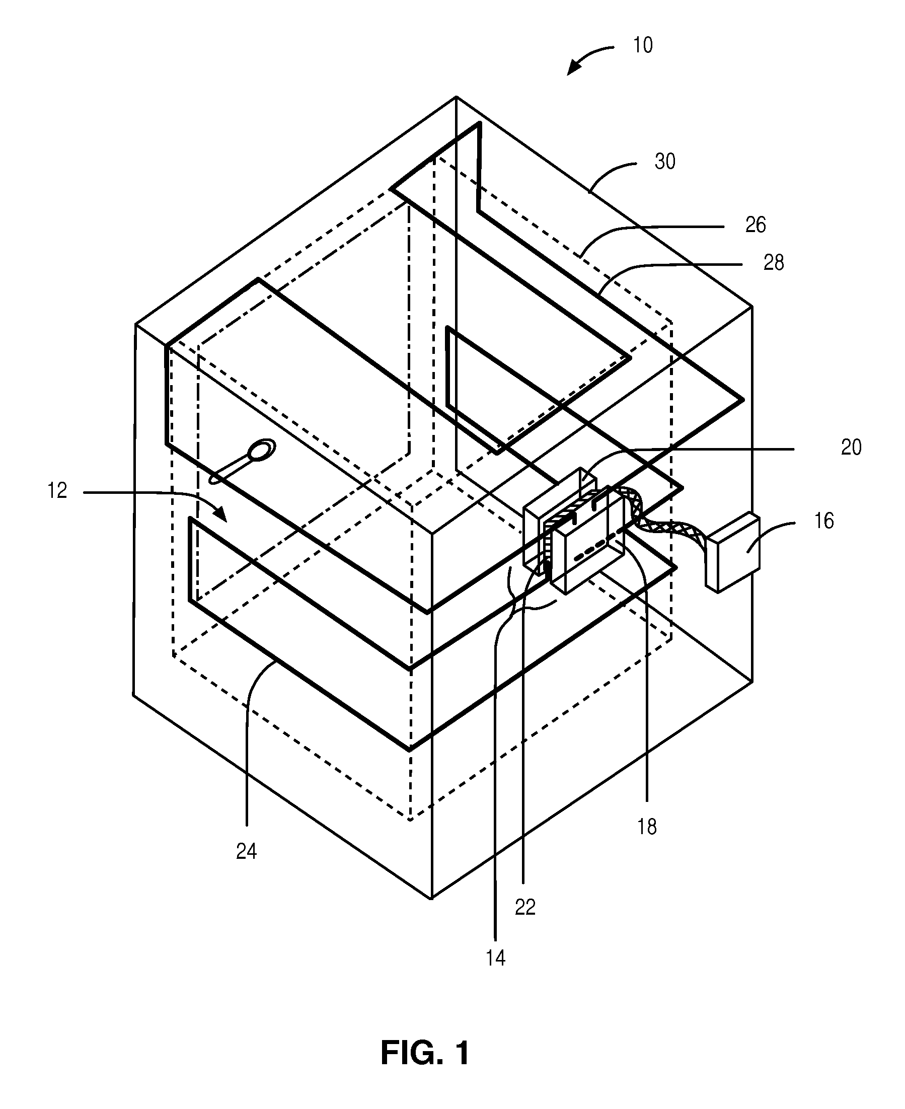
FIG. 1 illustrates a thermoelectric refrigeration system having a cooling chamber, a heat exchanger including at least one Thermoelectric Module (TEM) disposed between a cold side heat sink and a hot side heat sink, and a controller that controls the TEM according to some embodiments of the present disclosure;
FIG. 2 illustrates a relationship between a Coefficient of Performance of a TEM and an amount of power provided to the TEM for various ambient temperatures according to some embodiments of the present disclosure;
FIG. 3 illustrates a method of operating a TEM to increase efficiency of the TEM according to some embodiments of the present disclosure;
FIG. 4 illustrates a method for operating a thermoelectric refrigeration system when powered on or during pull down operation according to some embodiments of the present disclosure;
FIG. 5 illustrates a method for operating a thermoelectric refrigeration system near steady state operation according to some embodiments of the present disclosure;
FIG. 6 illustrates a method for operating a TEM to decrease the temperature of the hot side of the TEM according to some embodiments of the present disclosure;
FIG. 7 illustrates one possible implementation of the method of FIG. 6 according to some embodiments of the present disclosure;
FIG. 8 is a diagram of a controller for operating a TEM including modules according to some embodiments of the present disclosure; and
FIG. 9 is another diagram of a controller for operating a TEM including modules according to some embodiments of the present disclosure.
DETAILED DESCRIPTION
The embodiments set forth below represent the necessary information to enable those skilled in the art to practice the embodiments and illustrate the best mode of practicing the embodiments. Upon reading the following description in light of the accompanying drawing figures, those skilled in the art will understand the concepts of the disclosure and will recognize applications of these concepts not particularly addressed herein. It should be understood that these concepts and applications fall within the scope of the disclosure and the accompanying claims.
It will be understood that, although the terms first, second, etc. may be used herein to describe various elements, these elements should not be limited by these terms. These terms are only used to distinguish one element from another. For example, a first element could be termed a second element, and, similarly, a second element could be termed a first element, without departing from the scope of the present disclosure. As used herein, the term "and/or" includes any and all combinations of one or more of the associated listed items.
Relative terms such as "below" or "above" or "upper" or "lower" or "horizontal" or "vertical" may be used herein to describe a relationship of one element, layer, or region to another element, layer, or region as illustrated in the Figures. It will be understood that these terms and those discussed above are intended to encompass different orientations of the device in addition to the orientation depicted in the Figures.
The terminology used herein is for the purpose of describing particular embodiments only and is not intended to be limiting of the disclosure. As used herein, the singular forms "a," "an," and "the" are intended to include the plural forms as well, unless the context clearly indicates otherwise. It will be further understood that the terms "comprises," "comprising," "includes," and/or "including" when used herein specify the presence of stated features, integers, steps, operations, elements, and/or components, but do not preclude the presence or addition of one or more other features, integers, steps, operations, elements, components, and/or groups thereof.
Unless otherwise defined, all terms (including technical and scientific terms) used herein have the same meaning as commonly understood by one of ordinary skill in the art to which this disclosure belongs. It will be further understood that terms used herein should be interpreted as having a meaning that is consistent with their meaning in the context of this specification and the relevant art and will not be interpreted in an idealized or overly formal sense unless expressly so defined herein.
FIG. 1 illustrates a thermoelectric refrigeration system 10 having a cooling chamber 12, a heat exchanger 14 including at least one Thermoelectric Module (TEM) 22 (referred to herein singularly as TEM 22 or plural as TEMs 22) disposed between a cold side heat sink 20 and a hot side heat sink 18, and a controller 16 that controls the TEM 22 according to some embodiments of the present disclosure. When a TEM 22 is used to provide cooling it may sometimes be referred to as a Thermoelectric Cooler (TEC) 22.
The TEMs 22 are preferably thin film devices. When one or more of the TEMs 22 are activated by the controller 16, the activated TEMs 22 operate to heat the hot side heat sink 18 and cool the cold side heat sink 20 to thereby facilitate heat transfer to extract heat from the cooling chamber 12. More specifically, when one or more of the TEMs 22 are activated, the hot side heat sink 18 is heated to thereby create an evaporator and the cold side heat sink 20 is cooled to thereby create a condenser, according to some embodiments of the current disclosure.
Acting as a condenser, the cold side heat sink 20 facilitates heat extraction from the cooling chamber 12 via an accept loop 24 coupled with the cold side heat sink 20. The accept loop 24 is thermally coupled to an interior wall 26 of the thermoelectric refrigeration system 10. The interior wall 26 defines the cooling chamber 12. In one embodiment, the accept loop 24 is either integrated into the interior wall 26 or integrated directly onto the surface of the interior wall 26. The accept loop 24 is formed by any type of plumbing that allows for a cooling medium (e.g., a two-phase coolant) to flow or pass through the accept loop 24. Due to the thermal coupling of the accept loop 24 and the interior wall 26, the cooling medium extracts heat from the cooling chamber 12 as the cooling medium flows through the accept loop 24. The accept loop 24 may be formed of, for example, copper tubing, plastic tubing, stainless steel tubing, aluminum tubing, or the like.
Acting as an evaporator, the hot side heat sink 18 facilitates rejection of heat to an environment external to the cooling chamber 12 via a reject loop 28 coupled to the hot side heat sink 18. The reject loop 28 is thermally coupled to an outer wall 30, or outer skin, of the thermoelectric refrigeration system 10.
The thermal and mechanic processes for removing heat from the cooling chamber 12 are not discussed further. Also, it should be noted that the thermoelectric refrigeration system 10 shown in FIG. 1 is only a particular embodiment of a use and control of a TEM 22. All embodiments discussed herein should be understood to apply to thermoelectric refrigeration system 10 as well as any other use of a TEM 22.
Continuing with the example embodiment illustrated in FIG. 1, the controller 16 operates to control the TEMs 22 in order to maintain a desired set point temperature within the cooling chamber 12. In general, the controller 16 operates to selectively activate/deactivate the TEMs 22, selectively control an amount of power provided to the TEMs 22, and/or selectively control a duty cycle of the TEMs 22 to maintain the desired set point temperature. Further, in preferred embodiments, the controller 16 is enabled to separately, or independently, control one or more and, in some embodiments, two or more subsets of the TEMs 22, where each subset includes one or more different TEMs 22. Thus, as an example, if there are four TEMs 22, the controller 16 may be enabled to separately control a first individual TEM 22, a second individual TEM 22, and a group of two TEMs 22. By this method, the controller 16 can, for example, selectively activate one, two, three, or four TEMs 22 independently, at maximized efficiency, as demand dictates.
It should be noted that the thermoelectric refrigeration system 10 is only an example implementation and that the systems and methods disclosed herein are applicable to other systems as well. Also, while specific reference is made herein to the controller 16, it should be understood that any of the functions ascribed to the controller 16 could be implemented by any other controller or mechanism.
Before proceeding, a brief discussion of a cooling capacity versus an amount of power provided to a TEM 22 and efficiency versus an amount of power provided to a TEM 22 is beneficial. In this regard, FIG. 2 is a graph that illustrates cooling capacity (Q) and cooling efficiency of a TEC versus an input current of a TEC. The cooling efficiency is more specifically represented by a Coefficient of Performance (COP). FIG. 2 illustrates a relationship between a Coefficient of Performance (COP) of a TEM 22 and an amount of power provided to the TEM 22 for various ambient temperatures according to some embodiments of the present disclosure. The amount of power provided to the TEM 22 may be expressed as an amount of current provided to the TEM 22 and/or an amount of voltage provided to the TEM 22. As the amount of power provided to the TEM 22 increases, the cooling capacity of the TEM 22 also increases. The amount of power that is at or near a maximum amount of power for the TEM 22 is denoted as Q.sub.max. Thus, when the TEM 22 is operating at Q.sub.max, the TEM 22 is removing the greatest amount of heat possible. FIG. 2 illustrates the COP of the TEM 22 as a function of the amount of power provided to the TEM 22. For cooling applications, the COP of a TEM 22 is the ratio of heat removed over an amount of work input to the TEM 22 to remove the heat. The amount of heat, or capacity, (Q) at which the COP of the TEM 22 is maximized is denoted as Q.sub.COPmax. Thus, the efficiency, or COP, of the TEM 22 is maximized when the amount of power provided to the TEM 22 is at or near the point where the COP of the TEM 22 is maximized.
The shape of the COP curve for a TEM 22 is dependent upon variables such as operating ambient temperature (also referred to as the temperature of an environment that is external to the cooling chamber 12 or the temperature of the environment in which the TEM 22 is operating), an amount of heat being rejected, the temperature of the cold side of the TEM 22 (also sometimes referred to as the temperature of the cooling chamber 12 when the TEM 22 is operable to cool a cooling chamber 12), the temperature of the hot side of the TEM 22, an electrical property of the TEM 22 (such as the figure of merit), and the amount of power provided to the TEM 22. When one of these system parameters changes, the COP curve of the TEM 22 may change, and therefore the amount of power that would maximize the COP of the TEM 22 based on one or more of the system parameters may also change. FIG. 2 illustrates one example of this. Two COP curves are shown for a TEM 22 at ambient temperatures equal to 18 degrees Celsius (.degree. C.) and 25.degree. C. For simplicity, only the ambient temperature is changed while the other system parameters are fixed. In this example, when the ambient temperature changes from 18.degree. C. to 25.degree. C., the overall COP of the TEM 22 decreases. Notably, the amount of power that maximizes the COP of the TEM 22 also increases. A trend line is shown that gives a linear approximation of the relationship between the ambient temperature and the amount of power that maximizes the COP of the TEM 22. This trend line is only one example and other means of modelling or interpolating (or extrapolating) the relationship could be used.
Since the precise amount of power that maximizes the COP of the TEM 22 is based on many factors that might be changing, a range of acceptable amounts of power centered at the amount of power that maximizes the COP of the TEM 22 is determined. This range is referred to as a band, and any amount of power within that band is generally considered to be the amount of power that maximizes the COP of the TEM 22. In some embodiments the band is the amount of power that maximizes the COP of the TEM 22 plus or minus 10%, but this is implementation specific and may depend on the precision of determining the amount of power that maximizes the COP of the TEM 22 and/or the shape of the COP curve.
Since the most efficient way to operate the TEM 22 is to provide the amount of power that maximizes the COP of the TEM 22, the controller 16 or some other means of controlling the TEM 22 should seek to determine the amount of power that maximizes the COP of the TEM 22 based on one or more system parameters. As such, FIG. 3 illustrates a method of operating a TEM 22 to increase efficiency of the TEM 22 according to some embodiments of the present disclosure. The controller 16 determines a first amount of power that would maximize the COP of the TEM 22 based on one or more system parameters (step 100). As discussed above, this determination may be based on many different parameters. In some embodiments, the determination is based on only one parameter, such as ambient temperature, assuming other parameters to be constant or negligible. In some embodiments, the amount of power may be determined by consulting a lookup table. The controller 16 then provides the first amount of power to the TEM 22 (step 102). In this way, the TEM 22 is operating in the most efficient way for the current values of the system parameters.
The controller 16 next determines if at least one of the system parameters has changed (step 104). In some embodiments, then check may be performed periodically while in other embodiments the determination of the change may be almost immediate. Also, if the controller 16 is using less than all of the system parameters to determine the amount of power, then the controller 16 will not need to determine when any of the unused system parameters have changed. In response to the determination that at least one of the system parameters has changed, the controller 16 determines a second amount of power that would maximize the COP of the TEM 22 based on the one or more system parameters (step 106). The controller 16 then provides the second amount of power to the TEM 22 (step 108). In this way, the controller 16 can update the amount of power provided to the TEM 22 to increase the efficiency of the operation of the TEM 22. In some embodiments, the procedure optionally returns to step 104 and if one or more of the system parameters have changed, the controller 16 again determines an amount of power that would maximize the COP of the TEM 22.
Note that in some embodiments the updated amount of power may be calculated periodically or otherwise without the express determination that one or more of the system parameters have changed. Also, depending on the changes to the system parameters, the second amount of power may be the same or nearly the same as the first amount of power.
While FIG. 3 illustrates a method of operating a TEM 22 to increase efficiency of the TEM 22, FIGS. 4 and 5 illustrate methods for operating a thermoelectric refrigeration system 10 which may include one or more TEMs 22 as discussed above in relation to the example shown in FIG. 1. Specifically, FIG. 4 illustrates a method for operating a thermoelectric refrigeration system 10 when powered on or during pull down operation according to some embodiments of the present disclosure.
As used herein, pull down operation refers to the situation where the temperature in a cooling chamber 12 is higher than is acceptable and the controller 16 operates to reduce the temperature to an acceptable range. The desired temperature for the cooling chamber 12 is referred to as the set point temperature. Steady state operation refers to the situation where the temperature of the cooling chamber 12 is within a range that includes the set point temperature. This range provides a form of hysteresis to avoid the rapid oscillation between operating states. In some embodiments, the set point temperature may be 4.degree. C., and the steady state range may be from 3.degree. C. to 5.degree. C. If maintaining the set point temperature with greater precision is desired, then the steady state range may be smaller. If a decrease in the rate of oscillation between operating states is desired, then the steady state range may be smaller.
According to some embodiments, FIG. 4 begins with a power on or reset of the thermoelectric refrigeration system 10 (step 200). The thermoelectric refrigeration system 10 starts in this powered on or reset state during pull down operation because the temperature may be above the steady state range and due to be powered off. The controller 16 reads the set point register perhaps from a user interface on the front of the thermoelectric refrigeration system 10 or from a device Graphical User Interface (GUI) to determine the set point temperature (step 202). The controller 16 then measures the temperature control and the .DELTA.T of the at least one TEM 22 (step 204). .DELTA.T of a TEM 22 refers to the difference between the temperature of the hot side of the TEM 22 and the temperature of the cold side of the TEM 22. The controller 16 also measures the ambient temperature (step 206). The controller 16 may also determine any other system parameters that are necessary, depending on the implementation.
The controller 16 then performs a few safety checks according to some embodiments. The controller 16 checks if the ambient temperature is greater than or equal to 4.degree. C. (step 208). If the ambient temperature is less than 4.degree. C., the procedure returns to step 204 to again measure the various system parameters. If the ambient temperature is at least 4.degree. C., then the controller 16 then determines if the temperature of the heat exchanger is greater than or equal to a maximum limit (step 210).
In some embodiments, this temperature is the same as the temperature of the hot side of the TEM 22. Also, in some embodiments, instead of having a single maximum value, there is instead a test of whether the temperature is above a first threshold, and then when the hot side of the TEM 22 cools down there is a test of whether the temperature is below a second threshold. In this way, hysteresis can be optionally built into the overheating condition.
In some embodiments, the first threshold indicates that the hot side of the TEM 22 is saturated and cannot accept any additional heat. Also, the first threshold might indicate that the TEM 22 may be damaged by being operated at temperatures above the first threshold. Such high temperatures might occur when a large amount of heat is removed from the cooling chamber 12 or if the TEM 22 is being operated less efficiently. An accumulation of heat on the hot side of the TEM 22 may also occur when the reject side of the heat exchanger is insufficient to remove the heat at a faster rate than the heat is generated. This situation might occur when the hot side of the TEM 22 is passively cooled.
When the overheating condition is detected, the controller 16 sets an alarm (step 212). This alarm can take many forms depending on the embodiment. In some cases, the alarm is merely an internal state; while in other cases, the information may be presented on a display, or a user may be otherwise notified of the alarm. The controller 16 then determines if output to the TEM 22 is enabled (step 214). If output is not enabled, the controller 16 may not have any way of reducing the temperature of the hot side of the TEM 22 since no heat is being added by the operation of the TEM 22. In this case, the procedure returns to step 204 to again measure the various system parameters. In other embodiments, the controller 16 may have additional options for reducing the temperature of the hot side of the TEM 22 such as by using an active device such as a fan.
If output is enabled, the controller 16 determines if the amount of power being provided to the TEM 22 is the minimum power level (step 216). If it is not the minimum power level, the controller 16 decreases the amount of power provided to the TEM 22 by decrementing the output (step 218). If the current amount of power provided is the minimum power level, then the controller 16 powers off the output and issues a reset (step 220). Either way, the procedure returns to step 204 to again measure the various system parameters.
If the hot side of the TEM 22 is not overheated, the controller 16 clears any alarms that may be set (step 222). For instance, if an alarm had previously been set because of an overheating situation that has now been resolved, then that alarm will be cleared now. The controller 16 now determines if the temperature of the cooling chamber 12 is greater than an upper steady state limit (step 224). If the temperature is above the upper steady state limit, the thermoelectric refrigeration system 10 is considered to be in a pull down mode of operation.
If the temperature of the cooling chamber 12 is determined to be greater than or equal to an upper control limit (step 226), the controller 16 will set the output to 100%, providing the amount of power to the TEM 22 that is at or near a maximum amount of power for the TEM 22 (step 228). In such a way, the thermoelectric refrigeration system 10 can pull down the temperature of the cooling chamber 12 at the fastest rate, according to some embodiments. If the temperature of the cooling chamber 12 is determined to be less than the upper control limit, the controller 16 with set the output to proportional mode (step 230). In proportional mode, the temperature of the cooling chamber 12 may be decreased in a slower, more efficient manner. Either way, the procedure returns to step 204 to again measure the various system parameters.
If the controller 16 determines that the temperature of the cooling chamber 12 is less than an upper steady state limit, then the controller 16 determines if output is enabled (step 232). If output is not enabled, the procedure returns to step 204 to again measure the various system parameters. If output is enabled, the thermoelectric refrigeration system 10 is considered to be operating in steady state mode and the procedure continues on FIG. 5 which illustrates a method for operating a thermoelectric refrigeration system 10 near steady state operation according to some embodiments of the present disclosure.
As shown in FIG. 5, the controller 16 measures the temperature control and the .DELTA.T of the at least one TEM 22 (step 300). The controller 16 also determines any other system parameters that are necessary, such as the ambient temperature, depending on the implementation. Again, the controller 16 determines if the temperature of the heat exchanger is greater than or equal to a maximum limit (step 302). If the amount of power being provided to the TEM 22 is not the minimum power level (step 304), the controller 16 decreases the amount of power provided to the TEM 22 by decrementing the output (step 306). If the current amount of power provided is the minimum power level, then the controller 16 powers off the output and issues a reset (step 308). Either way, the procedure returns to step 300 to again measure the various system parameters.
If the hot side of the TEM 22 is not overheated, the controller 16 checks whether the temperature of the cooling chamber 12 is greater than the set point temperature (step 310). If the temperature of the cooling chamber 12 is less than the set point temperature, the controller 16 now determines if the temperature of the cooling chamber 12 is less than or equal to the steady state limit, the output is on, and .DELTA.T is in the current band (step 312). If all of these are true, the controller 16 powers off the TEM 22 and decreases the output to 0.x Volts, stores this value in the new steady state output value, and stores the previous value in the old steady state output value (step 314). If not all of these conditions are true, then the procedure returns to step 304 and attempts to decrease the amount of power provided to the TEM 22.
If the temperature of the cooling chamber 12 is greater than the set point temperature, the controller 16 determines if the temperature of the cooling chamber 12 is also greater than or equal to the steady state limit (step 316). If the temperature of the chamber is less than the steady state limit, the controller determines if the timer int has been set (step 318). If it has been set, the controller 16 sets the output to the old steady state output (step 320). After this, or if it has not been set, the procedure returns to step 300 to again measure the various system parameters.
If the temperature of the cooling chamber 12 is greater than or equal to the steady state limit, the controller 16 determines if the temperature of the chamber is greater than or equal to the upper control limit (step 322). If the chamber is greater than or equal to the upper control limit, the controller 16 will set the output to 100%, providing the amount of power to the TEM 22 that is at or near a maximum amount of power for the TEM 22 (step 324). This indicates that the thermoelectric refrigeration system 10 is considered to be in a pull down mode of operation, and the procedure returns to step 204 of FIG. 4 to again measure the various system parameters.
If the chamber is less than the upper control limit, the controller 16 will determine if the temperature of the cooling chamber 12 is greater than or equal to the hysteresis value (step 326). If it is not, the controller 16 increases the output to a new steady state output value (step 328), and the procedure returns to step 300 to again measure the various system parameters. According to some embodiments, this new steady state output value may be the amount of power that would maximize the COP of the TEM 22 based on one or more system parameters. If the temperature of the cooling chamber 12 is greater than or equal to the hysteresis value, this again indicates that the thermoelectric refrigeration system 10 is considered to be in a pull down mode of operation, and the procedure returns to step 204 of FIG. 4 to again measure the various system parameters.
As discussed above, overheating of the TEM 22 or the heat exchanger may cause undesired operation or be dangerous to the TEM 22. As such, both step 210 in FIG. 4 and step 302 in FIG. 5 check for such an overheating condition. While FIGS. 4 and 5 attempt to reduce the temperature of the TEM 22 by reducing the power and powering off the TEM 22, this may be undesirable or inefficient in some situations. As such, FIG. 6 illustrates a method for operating a TEM 22 to decrease the temperature of the hot side of the TEM 22 according to some embodiments of the present disclosure.
The controller 16 first provides a first amount of power to a TEM 22 (step 400). The controller 16 then determines if the temperature of the hot side of the TEM 22 is above a first threshold (step 402). As discussed previously, in some embodiments, the first threshold indicates that the hot side of the TEM 22 is saturated and cannot accept any additional heat. Also, the first threshold might indicate that the TEM 22 may be damaged by being operated at temperatures above the first threshold. If the temperature is not above the first threshold, the controller 16 continues to provide the first amount of power or operate according to any other control scheme that does not include overheating. If the temperature of the hot side of the TEM 22 is above the first threshold, the controller 16 provides a second amount of power to the TEM 22 that is less than the first amount of power (step 404). In some embodiments, this reduced power allows the temperature of the hot side of the TEM 22 to decrease while still operating the TEM 22.
In some embodiments, the controller 16 then determines if the temperature of the hot side of the TEM 22 is below a second threshold (step 406). This indicates that the TEM 22 has cooled down sufficiently and is no longer saturated. In some embodiments, the controller 16 will then provide a third amount of power to the TEM 22 which may be equal to the first amount of power but is not necessarily equal. FIG. 6 illustrates an embodiment where the procedure returns to step 400 and provides the first amount of power again. By increasing the power provided to the TEM 22, additional heat is able to be transferred.
In some embodiments, the first amount of power provided to the TEM 22 is at or near a maximum amount of power for the TEM 22. This is likely the case in a pull down mode of operation when the thermoelectric refrigeration system 10 is trying to remove heat as quickly as possible in order to reach the set point temperature. In some embodiments, the first amount of power provided to the TEM 22 is at or near the point where the COP of the TEM 22 is maximized. This is likely the case in a steady state mode of operation when the thermoelectric refrigeration system 10 is trying to remove the heat most efficiently.
In some embodiments, the second amount of power provided to the TEM 22 is at or near the point where the COP of the TEM 22 is maximized. In some embodiments, the second amount of power provided to the TEM 22 is at least an amount of power such that a temperature of the cooling chamber 12 does not increase. As discussed previously, in some embodiments, this mitigates heat rejection limitations of the TEM 22, especially when the hot side of the TEM 22 is passively cooled.
FIG. 7 illustrates one possible implementation of the method of FIG. 6 according to some embodiments of the present disclosure. FIG. 7 includes three lines. The top plots the temperature of the reject side (hot side) of the TEM 22. The bottom line plots the temperature of the cold side of the TEM 22. The middle line plots the power provided to the TEM 22 as the voltage applied to the TEM 22. At the beginning of the plot, the temperatures of the hot side and the cold side of the TEM 22 are similar. This may indicate that the thermoelectric refrigeration system 10 has just been powered on or that it is in pull down mode for some other reason such as being left open long enough.
At the beginning, the controller 16 provides a first voltage to the TEM 22. In this example, the temperature of the hot side of the TEM 22 increases while the temperature of the cold side of the TEM 22 decreases. In this example, the first threshold for the temperature of the hot side of the TEM 22 is 50.degree. C. When the controller 16 determines that the temperature of the hot side of the TEM 22 has reached 50.degree. C., the controller 16 reduces the power and provides a second amount of power to the TEM 22 that is less than the first amount. Because of this, less heat is being pumped to the hot side of the TEM 22 and it starts to cool down. Also, the temperature of the cold side of the TEM 22 has slowed its decrease or may be even rising slightly. This amount of power is provided to the TEM 22 until the controller 16 has determined that the hot side of the TEM 22 has cooled down enough.
When the controller 16 determines that the temperature of the hot side of the TEM 22 is below a second threshold, the controller 16 again provides the first amount of power to the TEM 22. This again causes the hot side of the TEM 22 to become overheated, but the cold side of the TEM 22 is now colder than it was when the hot side of the TEM 22 was last saturated. The controller 16 can continue this action of going between the two amounts of power to provide a quick pull down of the temperature of the cooling chamber 12 while mitigating heat rejection limitations of the TEM 22. This can be especially helpful when the hot side of the TEM 22 is passively cooled. While this example only shows two different amounts of power, the methods are not limited thereto. In some embodiments, either the larger amount of power or the smaller amount of power could be at or near the point where the COP of the TEM 22 is maximized, and this value may be recalculated each time based on the system parameters.
In other words, if this is a thermosyphon-based system, the cold side temperature is tied to an insulated chamber (e.g., cooling chamber 12). At the point where heat dissipation on the hot side has saturated and the further decrease of the cold side temperature is stalled, power to the TEM 22 is folded back to a level that will mitigate any elevation of the cold side temperature but allow the hot side temperature to decrease. This exploits the insulation of the cold side and its improved thermal stability over the hot side. Power is held reduced until the hot side temperature has lowered to a point that can allow for more heat rejection. When this point is reached, the TEM 22 power is increased, and the hot side or heat dissipation increases once again towards saturation. However, during this time, the cold side temperature will decrease since the hot side temperature is starting at a lower point. This cycling of power and temperature can be repeated many times to create a very slight pumping effect to augment natural convection around the hot side, allowing more overall heat to dissipate and allowing the cold side to reduce to its set point temperature.
FIG. 8 is a diagram of a controller 16 for operating a TEM 22 including a power determining module 32, a power providing module 34, and a system parameter determining module 36 according to some embodiments of the present disclosure. The power determining module 32, the power providing module 34, and the system parameter determining module 36 are each implemented in software that, when executed by a processor of the controller 16, causes the controller 16 to operate according to one of the embodiments described herein.
FIG. 9 is another diagram of a controller 16 for operating a TEM 22 including a power providing module 38 and a temperature determining module 40 according to some embodiments of the present disclosure. The power providing module 38 and the temperature determining module 40 are each implemented in software that, when executed by a processor of the controller 16, causes the controller 16 to operate according to one of the embodiments described herein.
Those skilled in the art will recognize improvements and modifications to the preferred embodiments of the present disclosure. All such improvements and modifications are considered within the scope of the concepts disclosed herein and the claims that follow.
* * * * *
References
D00000
D00001
D00002
D00003
D00004
D00005
D00006
D00007
D00008
XML
uspto.report is an independent third-party trademark research tool that is not affiliated, endorsed, or sponsored by the United States Patent and Trademark Office (USPTO) or any other governmental organization. The information provided by uspto.report is based on publicly available data at the time of writing and is intended for informational purposes only.
While we strive to provide accurate and up-to-date information, we do not guarantee the accuracy, completeness, reliability, or suitability of the information displayed on this site. The use of this site is at your own risk. Any reliance you place on such information is therefore strictly at your own risk.
All official trademark data, including owner information, should be verified by visiting the official USPTO website at www.uspto.gov. This site is not intended to replace professional legal advice and should not be used as a substitute for consulting with a legal professional who is knowledgeable about trademark law.