Method of electrically contacting a bond pad of a device under test with a probe
Smith
U.S. patent number 10,267,848 [Application Number 15/222,113] was granted by the patent office on 2019-04-23 for method of electrically contacting a bond pad of a device under test with a probe. This patent grant is currently assigned to FormFactor Beaverton, Inc.. The grantee listed for this patent is Cascade Microtech, Inc.. Invention is credited to Kenneth R. Smith.


View All Diagrams
| United States Patent | 10,267,848 |
| Smith | April 23, 2019 |
Method of electrically contacting a bond pad of a device under test with a probe
Abstract
The contacts of a probing apparatus are elastically supported on a replaceable coupon and electrically interconnected with conductors on a membrane or a space transformer.
| Inventors: | Smith; Kenneth R. (Beaverton, OR) | ||||||||||
|---|---|---|---|---|---|---|---|---|---|---|---|
| Applicant: |
|
||||||||||
| Assignee: | FormFactor Beaverton, Inc.
(Beaverton, OR) |
||||||||||
| Family ID: | 42195639 | ||||||||||
| Appl. No.: | 15/222,113 | ||||||||||
| Filed: | July 28, 2016 |
Prior Publication Data
| Document Identifier | Publication Date | |
|---|---|---|
| US 20160334465 A1 | Nov 17, 2016 | |
Related U.S. Patent Documents
| Application Number | Filing Date | Patent Number | Issue Date | ||
|---|---|---|---|---|---|
| 13854725 | Apr 1, 2013 | 9429638 | |||
| 12592186 | Apr 2, 2013 | 8410806 | |||
| 61199910 | Nov 21, 2008 | ||||
| Current U.S. Class: | 1/1 |
| Current CPC Class: | G01R 35/00 (20130101); G01R 1/06711 (20130101); G01R 31/2891 (20130101); B32B 38/10 (20130101); G01R 1/0735 (20130101); Y10T 29/49126 (20150115); G01R 1/06772 (20130101); Y10T 29/49208 (20150115) |
| Current International Class: | H01R 43/20 (20060101); G01R 1/067 (20060101); G01R 31/28 (20060101); G01R 35/00 (20060101); B32B 38/10 (20060101); G01R 1/073 (20060101) |
| Field of Search: | ;29/876,402.01,402.08,402.11,874,877 ;156/64,98 |
References Cited [Referenced By]
U.S. Patent Documents
| 1337866 | April 1920 | Whitaker |
| 2142625 | January 1939 | Zoethout |
| 2376101 | May 1945 | Tyzzer |
| 2389668 | November 1945 | Johnson |
| 3176091 | March 1965 | Hanson et al. |
| 3193712 | July 1965 | Harris |
| 3230299 | January 1966 | Radziejowski |
| 3401126 | September 1968 | Miller et al. |
| 3429040 | February 1969 | Miller |
| 3441315 | April 1969 | Paes et al. |
| 3442831 | May 1969 | Dickstein et al. |
| 3445770 | May 1969 | Harmon |
| 3484679 | December 1969 | Hodgson et al. |
| 3541222 | November 1970 | Parks et al. |
| 3595228 | July 1971 | Simon et al. |
| 3596228 | July 1971 | Reed, Jr. et al. |
| 3609539 | September 1971 | Gunthert |
| 3634807 | January 1972 | Grobe et al. |
| 3654585 | April 1972 | Wickersham |
| 3680037 | July 1972 | Nellis et al. |
| 3700998 | October 1972 | Lee et al. |
| 3710251 | January 1973 | Hagge et al. |
| 3714572 | January 1973 | Ham et al. |
| 3740900 | June 1973 | Youmans et al. |
| 3806801 | April 1974 | Bove |
| 3829076 | August 1974 | Sofy |
| 3839672 | October 1974 | Anderson |
| 3849728 | November 1974 | Evans |
| 3858212 | December 1974 | Tompkins et al. |
| 3862790 | January 1975 | Davies et al. |
| 3866093 | February 1975 | Kusters et al. |
| 3936743 | February 1976 | Roch |
| 3952156 | April 1976 | Lahr |
| 3970934 | July 1976 | Aksu |
| 3971610 | July 1976 | Buchoff et al. |
| 3976959 | August 1976 | Gaspari |
| 3992073 | November 1976 | Buchoff et al. |
| 4008900 | February 1977 | Khoshaba |
| 4027935 | June 1977 | Byrnes et al. |
| 4038599 | July 1977 | Bove et al. |
| 4038894 | August 1977 | Knibbe et al. |
| 4049252 | September 1977 | Bell |
| 4066943 | January 1978 | Roch |
| 4072576 | February 1978 | Arwin et al. |
| 4093988 | June 1978 | Scott |
| 4099120 | July 1978 | Aksu |
| 4115735 | September 1978 | Stanford |
| 4135131 | January 1979 | Larsen et al. |
| 4184729 | January 1980 | Parks et al. |
| 4275446 | June 1981 | Blaess |
| 4277741 | July 1981 | Faxvog et al. |
| 4284033 | August 1981 | del Rio |
| 4284682 | August 1981 | Frosch et al. |
| 4287473 | September 1981 | Sawyer |
| 4306235 | December 1981 | Christmann |
| 4312117 | January 1982 | Robillard et al. |
| 4327180 | April 1982 | Chen |
| 4330783 | May 1982 | Toia |
| 4357575 | November 1982 | Uren et al. |
| 4376920 | March 1983 | Smith |
| 4383217 | May 1983 | Shiell |
| 4401945 | August 1983 | Juengel |
| 4425395 | January 1984 | Negishi et al. |
| 4453142 | June 1984 | Murphy |
| 4468629 | August 1984 | Choma, Jr. |
| 4487996 | December 1984 | Rabinowitz et al. |
| 4515133 | May 1985 | Roman |
| 4515439 | May 1985 | Esswein |
| 4528504 | July 1985 | Thornton, Jr. et al. |
| 4531474 | July 1985 | Inuta |
| 4552033 | November 1985 | Marzhauser |
| 4567321 | January 1986 | Harayama |
| 4568890 | February 1986 | Bates |
| 4581679 | April 1986 | Smolley |
| 4588950 | May 1986 | Henley |
| 4593243 | June 1986 | Lao et al. |
| 4600907 | July 1986 | Grellman et al. |
| 4621169 | November 1986 | Petinelli et al. |
| 4626618 | December 1986 | Takaoka et al. |
| 4636722 | January 1987 | Ardezzone |
| 4636772 | January 1987 | Yasunaga |
| 4641659 | February 1987 | Sepponen |
| 4642417 | February 1987 | Ruthrof et al. |
| 4646005 | February 1987 | Ryan |
| 4649339 | March 1987 | Grangroth et al. |
| 4651115 | March 1987 | Wu |
| 4663840 | May 1987 | Ubbens et al. |
| 4673839 | June 1987 | Veenendaal |
| 4684883 | August 1987 | Ackerman et al. |
| 4691163 | September 1987 | Blass et al. |
| 4697143 | September 1987 | Lockwood et al. |
| 4705447 | November 1987 | Smith |
| 4707657 | November 1987 | Boegh-Petersen |
| 4711563 | December 1987 | Lass |
| 4713347 | December 1987 | Mitchell et al. |
| 4719417 | January 1988 | Evans |
| 4725793 | February 1988 | Igarashi |
| 4727391 | February 1988 | Tajima et al. |
| 4727637 | March 1988 | Buckwitz et al. |
| 4742571 | May 1988 | Letron |
| 4744041 | May 1988 | Strunk et al. |
| 4746857 | May 1988 | Sakai et al. |
| 4749942 | June 1988 | Sang et al. |
| 4754239 | June 1988 | Sedivec |
| 4755746 | July 1988 | Mallory et al. |
| 4755747 | July 1988 | Sato |
| 4755874 | July 1988 | Esrig et al. |
| 4757255 | July 1988 | Margozzi |
| 4766384 | August 1988 | Kleinberg et al. |
| 4772846 | September 1988 | Reeds |
| 4780670 | October 1988 | Cherry |
| 4791363 | December 1988 | Logan |
| 4793814 | December 1988 | Zifcak et al. |
| 4795962 | January 1989 | Yanagawa et al. |
| 4805627 | February 1989 | Klingenbeck et al. |
| 4812754 | March 1989 | Tracey et al. |
| 4827211 | May 1989 | Strid et al. |
| 4831494 | May 1989 | Arnold et al. |
| 4835495 | May 1989 | Simonutti |
| 4837507 | June 1989 | Hechtman |
| 4839587 | June 1989 | Flatley et al. |
| 4849689 | July 1989 | Gleason et al. |
| 4853624 | August 1989 | Rabjohn |
| 4853627 | August 1989 | Gleason et al. |
| 4859989 | August 1989 | McPherson |
| 4864227 | September 1989 | Sato |
| 4871883 | October 1989 | Guiol |
| 4871964 | October 1989 | Boll et al. |
| 4891584 | January 1990 | Kamieniecki et al. |
| 4893914 | January 1990 | Hancock et al. |
| 4894612 | January 1990 | Drake et al. |
| 4899998 | February 1990 | Teramachi |
| 4904933 | February 1990 | Snyder et al. |
| 4904935 | February 1990 | Calma et al. |
| 4906920 | March 1990 | Huff et al. |
| 4912399 | March 1990 | Greub et al. |
| 4916002 | April 1990 | Carver |
| 4916398 | April 1990 | Rath |
| 4918383 | April 1990 | Huff et al. |
| 4922128 | May 1990 | Dhong et al. |
| 4922186 | May 1990 | Tsuchiya et al. |
| 4922192 | May 1990 | Gross et al. |
| 4929893 | May 1990 | Sato et al. |
| 4975638 | December 1990 | Evans et al. |
| 4980637 | December 1990 | Huff et al. |
| 4983910 | January 1991 | Majidi-Ahy et al. |
| 4987100 | January 1991 | McBride et al. |
| 4991290 | February 1991 | MacKay |
| 4998062 | March 1991 | Ikeda |
| 5001423 | March 1991 | Abrami et al. |
| 5003253 | March 1991 | Majidi-Ahy et al. |
| 5020219 | June 1991 | Leedy |
| 5021186 | June 1991 | Ota et al. |
| 5030907 | July 1991 | Yih et al. |
| 5041782 | August 1991 | Marzan |
| 5045781 | September 1991 | Gleason et al. |
| 5059898 | October 1991 | Barsotti et al. |
| 5061192 | October 1991 | Chapin et al. |
| 5061823 | October 1991 | Carroll |
| 5066357 | November 1991 | Smyth, Jr. et al. |
| 5069628 | December 1991 | Crumly |
| 5082627 | January 1992 | Stanbro |
| 5084671 | January 1992 | Miyata et al. |
| 5089774 | February 1992 | Nakano |
| 5091692 | February 1992 | Ohno et al. |
| 5091732 | February 1992 | Mileski et al. |
| 5095891 | March 1992 | Reitter |
| 5097101 | March 1992 | Trobough |
| 5097207 | March 1992 | Blanz |
| 5107076 | April 1992 | Bullock et al. |
| 5126286 | June 1992 | Chance |
| 5126696 | June 1992 | Grote et al. |
| 5133119 | July 1992 | Afshari et al. |
| 5134365 | July 1992 | Okubo et al. |
| 5136237 | August 1992 | Smith et al. |
| 5138289 | August 1992 | McGrath |
| 5142224 | August 1992 | Smith et al. |
| 5145552 | September 1992 | Yoshizawa et al. |
| 5148103 | September 1992 | Pasiecznik, Jr. |
| 5159264 | October 1992 | Anderson |
| 5159267 | October 1992 | Anderson |
| 5159752 | November 1992 | Mahant-Shetti et al. |
| 5160883 | November 1992 | Blanz |
| 5164319 | November 1992 | Hafeman et al. |
| 5166606 | November 1992 | Blanz |
| 5172049 | December 1992 | Kiyokawa et al. |
| 5172050 | December 1992 | Swapp |
| 5172051 | December 1992 | Zamborelli |
| 5177438 | January 1993 | Littlebury et al. |
| 5180977 | January 1993 | Huff |
| 5187443 | February 1993 | Bereskin |
| 5198752 | March 1993 | Miyata et al. |
| 5198753 | March 1993 | Hamburgen |
| 5202558 | April 1993 | Barker |
| 5202648 | April 1993 | McCandless |
| 5207585 | May 1993 | Byrnes et al. |
| 5214243 | May 1993 | Johnson |
| 5214374 | May 1993 | St. Onge |
| 5225037 | July 1993 | Elder et al. |
| 5227730 | July 1993 | King et al. |
| 5232789 | August 1993 | Platz et al. |
| 5233197 | August 1993 | Bowman et al. |
| 5233306 | August 1993 | Misra |
| 5245292 | September 1993 | Milesky et al. |
| 5266889 | November 1993 | Harwood et al. |
| 5267088 | November 1993 | Nomura |
| 5270664 | December 1993 | McMurtry et al. |
| 5274336 | December 1993 | Crook et al. |
| 5280156 | January 1994 | Niori et al. |
| 5293175 | March 1994 | Hemmie et al. |
| 5298972 | March 1994 | Heffner |
| 5304924 | April 1994 | Yamano et al. |
| 5313157 | May 1994 | Pasiecznik, Jr. |
| 5315237 | May 1994 | Iwakura et al. |
| 5321352 | June 1994 | Takebuchi |
| 5321453 | June 1994 | Mori et al. |
| 5326412 | July 1994 | Schreiber et al. |
| 5355079 | October 1994 | Evans et al. |
| 5357211 | October 1994 | Bryson et al. |
| 5361049 | November 1994 | Rubin et al. |
| 5363050 | November 1994 | Guo et al. |
| 5367165 | November 1994 | Toda et al. |
| 5368634 | November 1994 | Hackett |
| 5369368 | November 1994 | Kassen et al. |
| 5371654 | December 1994 | Beaman et al. |
| 5373231 | December 1994 | Boll et al. |
| 5374938 | December 1994 | Hatazawa et al. |
| 5376790 | December 1994 | Linker et al. |
| 5389885 | February 1995 | Swart |
| 5395253 | March 1995 | Crumly |
| 5397855 | March 1995 | Ferlier |
| 5404111 | April 1995 | Mori et al. |
| 5408188 | April 1995 | Katoh |
| 5408189 | April 1995 | Swart et al. |
| 5412330 | May 1995 | Ravel et al. |
| 5412866 | May 1995 | Woith et al. |
| 5414565 | May 1995 | Sullivan et al. |
| 5422574 | June 1995 | Kister |
| 5441690 | August 1995 | Ayala-Esquilin et al. |
| 5451722 | September 1995 | Gregoire |
| 5451884 | September 1995 | Sauerland |
| 5453404 | September 1995 | Leedy |
| 5457398 | October 1995 | Schwindt et al. |
| 5467024 | November 1995 | Swapp |
| 5469324 | November 1995 | Henderson et al. |
| 5475316 | December 1995 | Hurley et al. |
| 5476211 | December 1995 | Khandros |
| 5477011 | December 1995 | Singles et al. |
| 5478748 | December 1995 | Akins, Jr. et al. |
| 5479108 | December 1995 | Cheng |
| 5479109 | December 1995 | Lau et al. |
| 5481196 | January 1996 | Nosov |
| 5481936 | January 1996 | Yanagisawa |
| 5487999 | January 1996 | Farnworth |
| 5488954 | February 1996 | Sleva et al. |
| 5493070 | February 1996 | Habu |
| 5493236 | February 1996 | Ishii et al. |
| 5500606 | March 1996 | Holmes |
| 5505150 | April 1996 | James et al. |
| 5506498 | April 1996 | Anderson et al. |
| 5506515 | April 1996 | Godshalk et al. |
| 5510792 | April 1996 | Ono et al. |
| 5511010 | April 1996 | Burns |
| 5512835 | April 1996 | Rivera et al. |
| 5517126 | May 1996 | Yamaguchi |
| 5521518 | May 1996 | Higgins |
| 5521522 | May 1996 | Abe et al. |
| 5523694 | June 1996 | Cole, Jr. |
| 5528158 | June 1996 | Sinsheimer et al. |
| 5530372 | June 1996 | Lee et al. |
| 5531022 | July 1996 | Beaman et al. |
| 5532608 | July 1996 | Behfar-Rad et al. |
| 5537372 | July 1996 | Albrecht et al. |
| 5539323 | July 1996 | Davis, Jr. |
| 5539676 | July 1996 | Yamaguchi |
| 5565788 | October 1996 | Burr et al. |
| 5565881 | October 1996 | Phillips et al. |
| 5569591 | October 1996 | Kell et al. |
| 5571324 | November 1996 | Sago et al. |
| 5578932 | November 1996 | Adamian |
| 5583445 | December 1996 | Mullen |
| 5584120 | December 1996 | Roberts |
| 5584608 | December 1996 | Gillespie |
| 5589781 | December 1996 | Higgins et al. |
| 5600256 | February 1997 | Woith et al. |
| 5601740 | February 1997 | Eldridge et al. |
| 5610529 | March 1997 | Schwindt |
| 5611008 | March 1997 | Yap |
| 5617035 | April 1997 | Swapp |
| 5623213 | April 1997 | Liu et al. |
| 5623214 | April 1997 | Pasiecznik, Jr. |
| 5628057 | May 1997 | Phillips et al. |
| 5631571 | May 1997 | Spaziani et al. |
| 5633780 | May 1997 | Cronin |
| 5634267 | June 1997 | Farnworth et al. |
| 5635846 | June 1997 | Beaman et al. |
| 5642298 | June 1997 | Mallory et al. |
| 5644248 | July 1997 | Fujimoto |
| 5653939 | August 1997 | Hollis et al. |
| 5656942 | August 1997 | Watts et al. |
| 5659421 | August 1997 | Rahmel et al. |
| 5666063 | September 1997 | Abercrombie et al. |
| 5669316 | September 1997 | Faz et al. |
| 5670322 | September 1997 | Eggers et al. |
| 5670888 | September 1997 | Cheng |
| 5672816 | September 1997 | Park et al. |
| 5675499 | October 1997 | Lee et al. |
| 5675932 | October 1997 | Mauney |
| 5676360 | October 1997 | Boucher et al. |
| 5685232 | November 1997 | Inoue |
| 5686317 | November 1997 | Akram et al. |
| 5688618 | November 1997 | Hulderman et al. |
| 5700844 | December 1997 | Hedrik et al. |
| 5704355 | January 1998 | Bridges |
| 5715819 | February 1998 | Svenson et al. |
| 5720098 | February 1998 | Kister |
| 5723347 | March 1998 | Hirano et al. |
| 5726211 | March 1998 | Hedrick et al. |
| 5731920 | March 1998 | Katsuragawa |
| 5742174 | April 1998 | Kister et al. |
| 5744383 | April 1998 | Fritz |
| 5744971 | April 1998 | Chan et al. |
| 5748506 | May 1998 | Bockelman |
| 5751252 | May 1998 | Phillips |
| 5756021 | May 1998 | Hedrick et al. |
| 5767690 | June 1998 | Fujimoto |
| 5772451 | June 1998 | Dozier, II et al. |
| 5773780 | June 1998 | Eldridge et al. |
| 5777485 | July 1998 | Tanaka et al. |
| 5785538 | July 1998 | Beaman et al. |
| 5792668 | August 1998 | Fuller et al. |
| 5793213 | August 1998 | Bockelman et al. |
| 5794133 | August 1998 | Kashima |
| 5804607 | September 1998 | Hedrick et al. |
| 5804982 | September 1998 | Lo et al. |
| 5804983 | September 1998 | Nakajima et al. |
| 5806181 | September 1998 | Khandros et al. |
| 5807107 | September 1998 | Bright et al. |
| 5810607 | September 1998 | Shih et al. |
| 5810609 | September 1998 | Faraci et al. |
| 5811751 | September 1998 | Leong et al. |
| 5811982 | September 1998 | Beaman et al. |
| 5813847 | September 1998 | Eroglu et al. |
| 5814847 | September 1998 | Shihadeh et al. |
| 5820014 | October 1998 | Dozier, II et al. |
| 5821763 | October 1998 | Beaman et al. |
| 5824494 | October 1998 | Feldberg |
| 5829128 | November 1998 | Eldridge et al. |
| 5829437 | November 1998 | Bridges |
| 5831442 | November 1998 | Heigl |
| 5832601 | November 1998 | Eldridge et al. |
| 5833601 | November 1998 | Swartz et al. |
| 5838160 | November 1998 | Beaman et al. |
| 5841288 | November 1998 | Meaney et al. |
| 5846708 | December 1998 | Hollis et al. |
| 5847569 | December 1998 | Ho et al. |
| 5848500 | December 1998 | Kirk |
| 5852232 | December 1998 | Samsavar et al. |
| 5854608 | December 1998 | Leisten |
| 5864946 | February 1999 | Eldridge et al. |
| 5867073 | February 1999 | Weinreb et al. |
| 5869326 | February 1999 | Hofmann |
| 5869974 | February 1999 | Akram et al. |
| 5874361 | February 1999 | Collins et al. |
| 5876082 | March 1999 | Kempf et al. |
| 5878486 | March 1999 | Eldridge et al. |
| 5883522 | March 1999 | O'Boyle |
| 5883523 | March 1999 | Ferland et al. |
| 5884398 | March 1999 | Eldridge et al. |
| 5888075 | March 1999 | Hasegawa et al. |
| 5892539 | April 1999 | Colvin |
| 5896038 | April 1999 | Budnaitis et al. |
| 5896326 | April 1999 | Akashi |
| 5900737 | May 1999 | Graham et al. |
| 5900738 | May 1999 | Khandros et al. |
| 5903143 | May 1999 | Mochizuki et al. |
| 5905421 | May 1999 | Oldfield |
| 5910727 | June 1999 | Fujihara et al. |
| 5912046 | June 1999 | Eldridge et al. |
| 5914613 | June 1999 | Gleason et al. |
| 5914614 | June 1999 | Beaman et al. |
| 5916689 | June 1999 | Collins et al. |
| 5917707 | June 1999 | Khandros et al. |
| 5926029 | July 1999 | Ference et al. |
| 5926951 | July 1999 | Khandros et al. |
| 5944093 | August 1999 | Viswanath |
| 5945836 | August 1999 | Sayre et al. |
| 5949383 | September 1999 | Hayes et al. |
| 5949579 | September 1999 | Baker |
| 5959461 | September 1999 | Brown et al. |
| 5963364 | October 1999 | Leong et al. |
| 5970429 | October 1999 | Martin |
| 5973504 | October 1999 | Chong |
| 5981268 | November 1999 | Kovacs et al. |
| 5982166 | November 1999 | Mautz |
| 5983493 | November 1999 | Eldridge et al. |
| 5990695 | November 1999 | Daugherty, Jr. |
| 5993611 | November 1999 | Moroney, III et al. |
| 5994152 | November 1999 | Khandros et al. |
| 5995914 | November 1999 | Cabot |
| 5996102 | November 1999 | Haulin |
| 5998228 | December 1999 | Eldridge et al. |
| 5998768 | December 1999 | Hunter et al. |
| 5998864 | December 1999 | Khandros et al. |
| 5999268 | December 1999 | Yonezawa et al. |
| 6001760 | December 1999 | Katsuda et al. |
| 6002426 | December 1999 | Back et al. |
| 6013586 | January 2000 | McGhee et al. |
| 6019612 | February 2000 | Hasegawa et al. |
| 6020745 | February 2000 | Taraci |
| 6023103 | February 2000 | Chang et al. |
| 6028435 | February 2000 | Nikawa |
| 6029344 | February 2000 | Khandros et al. |
| 6031383 | February 2000 | Streib et al. |
| 6032356 | March 2000 | Eldridge et al. |
| 6032714 | March 2000 | Fenton |
| 6033935 | March 2000 | Dozier, II et al. |
| 6034533 | March 2000 | Tervo et al. |
| 6037785 | March 2000 | Higgins |
| 6040739 | March 2000 | Wedeen et al. |
| 6042712 | March 2000 | Mathieu |
| 6043563 | March 2000 | Eldridge et al. |
| 6049216 | April 2000 | Yang et al. |
| 6049976 | April 2000 | Khandros |
| 6050829 | April 2000 | Eldridge et al. |
| 6051422 | April 2000 | Kovacs et al. |
| 6052653 | April 2000 | Mazur et al. |
| 6054651 | April 2000 | Fogel et al. |
| 6054869 | April 2000 | Hutton et al. |
| 6059982 | May 2000 | Palagonia et al. |
| 6060888 | May 2000 | Blackham et al. |
| 6060892 | May 2000 | Yamagata |
| 6061589 | May 2000 | Bridges et al. |
| 6062879 | May 2000 | Beaman et al. |
| 6064213 | May 2000 | Khandros et al. |
| 6064217 | May 2000 | Smith |
| 6064218 | May 2000 | Godfrey et al. |
| 6066911 | May 2000 | Lindemann et al. |
| 6075376 | June 2000 | Schwindt |
| 6078183 | June 2000 | Cole, Jr. |
| 6078500 | June 2000 | Beaman et al. |
| 6090261 | July 2000 | Mathieu |
| 6091236 | July 2000 | Piety et al. |
| 6091255 | July 2000 | Godfrey |
| 6096567 | August 2000 | Kaplan et al. |
| 6100815 | August 2000 | Pailthorp |
| 6104201 | August 2000 | Beaman et al. |
| 6104206 | August 2000 | Verkuil |
| 6110823 | August 2000 | Eldridge et al. |
| 6114864 | September 2000 | Soejima et al. |
| 6114865 | September 2000 | Lagowski et al. |
| 6118287 | September 2000 | Boll et al. |
| 6118894 | September 2000 | Schwartz et al. |
| 6124725 | September 2000 | Sato |
| 6127831 | October 2000 | Khoury et al. |
| 6137302 | October 2000 | Schwindt |
| 6144212 | November 2000 | Mizuta |
| 6147502 | November 2000 | Fryer et al. |
| 6147851 | November 2000 | Anderson |
| 6150186 | November 2000 | Chen et al. |
| 6160407 | December 2000 | Nikawa |
| 6160412 | December 2000 | Martel et al. |
| 6166333 | December 2000 | Crumly et al. |
| 6166553 | December 2000 | Sinsheimer |
| 6168974 | January 2001 | Chang et al. |
| 6169410 | January 2001 | Grace et al. |
| 6172337 | January 2001 | Johnsgard et al. |
| 6174744 | January 2001 | Watanabe et al. |
| 6175228 | January 2001 | Zamborelli et al. |
| 6176091 | January 2001 | Kishi et al. |
| 6181144 | January 2001 | Hembree et al. |
| 6181149 | January 2001 | Godfrey et al. |
| 6181297 | January 2001 | Leisten |
| 6181416 | January 2001 | Falk |
| 6184053 | February 2001 | Eldridge et al. |
| 6184587 | February 2001 | Khandros et al. |
| 6184845 | February 2001 | Leisten et al. |
| 6191596 | February 2001 | Abiko |
| 6194720 | February 2001 | Li et al. |
| 6206273 | March 2001 | Beaman et al. |
| 6208225 | March 2001 | Miller |
| 6211663 | April 2001 | Moulthrop et al. |
| 6211837 | April 2001 | Crouch et al. |
| 6215196 | April 2001 | Eldridge et al. |
| 6215295 | April 2001 | Smith, III |
| 6215670 | April 2001 | Khandros |
| 6218910 | April 2001 | Miller |
| 6222031 | April 2001 | Wakabayashi et al. |
| 6229327 | May 2001 | Boll et al. |
| 6232149 | May 2001 | Dozier, II et al. |
| 6232787 | May 2001 | Lo et al. |
| 6232788 | May 2001 | Schwindt et al. |
| 6233613 | May 2001 | Walker et al. |
| 6236223 | May 2001 | Brady et al. |
| 6242803 | June 2001 | Khandros et al. |
| 6242929 | June 2001 | Mizuta |
| 6245692 | June 2001 | Pearce et al. |
| 6246247 | June 2001 | Eldridge et al. |
| 6250933 | June 2001 | Khoury et al. |
| 6251595 | June 2001 | Gordon et al. |
| 6255126 | July 2001 | Mathieu et al. |
| 6256882 | July 2001 | Gleason et al. |
| 6257564 | July 2001 | Avneri et al. |
| 6265950 | July 2001 | Schmidt et al. |
| 6268015 | July 2001 | Mathieu et al. |
| 6268016 | July 2001 | Bhatt et al. |
| 6271673 | August 2001 | Furuta et al. |
| 6274823 | August 2001 | Khandros et al. |
| 6275738 | August 2001 | Kasevich et al. |
| 6278051 | August 2001 | Peabody |
| 6278411 | August 2001 | Ohlsson et al. |
| 6281691 | August 2001 | Matsunaga et al. |
| 6286208 | September 2001 | Shih et al. |
| 6292760 | September 2001 | Burns |
| 6295729 | October 2001 | Beaman et al. |
| 6300775 | October 2001 | Peach et al. |
| 6300780 | October 2001 | Beaman et al. |
| 6307161 | October 2001 | Grube et al. |
| 6307387 | October 2001 | Gleason et al. |
| 6307672 | October 2001 | DeNure |
| 6310483 | October 2001 | Taura et al. |
| 6320372 | November 2001 | Keller |
| 6320396 | November 2001 | Nikawa |
| 6327034 | December 2001 | Hoover et al. |
| 6329827 | December 2001 | Beaman et al. |
| 6330164 | December 2001 | Khandros et al. |
| 6332270 | December 2001 | Beaman et al. |
| 6334247 | January 2002 | Beaman et al. |
| 6335625 | January 2002 | Bryant et al. |
| 6339338 | January 2002 | Eldridge et al. |
| 6340568 | January 2002 | Hefti |
| 6340895 | January 2002 | Uher et al. |
| 6351885 | March 2002 | Suzuki et al. |
| 6352454 | March 2002 | Kim et al. |
| 6359456 | March 2002 | Hembree et al. |
| 6362792 | March 2002 | Sawamura et al. |
| 6366247 | April 2002 | Sawamura et al. |
| 6369776 | April 2002 | Leisten et al. |
| 6376258 | April 2002 | Hefti |
| 6384614 | May 2002 | Hager et al. |
| 6395480 | May 2002 | Hefti |
| 6396296 | May 2002 | Tartar et al. |
| 6396298 | May 2002 | Young et al. |
| 6400168 | June 2002 | Matsunaga et al. |
| 6404211 | June 2002 | Hamel et al. |
| 6404213 | June 2002 | Noda |
| 6407562 | June 2002 | Whiteman |
| 6409724 | June 2002 | Penney et al. |
| 6414478 | July 2002 | Suzuki |
| 6415858 | July 2002 | Getchel et al. |
| 6418009 | July 2002 | Brunette |
| 6419500 | July 2002 | Kister |
| 6420722 | July 2002 | Moore et al. |
| 6420887 | July 2002 | Kister et al. |
| 6424164 | July 2002 | Kister |
| 6424316 | July 2002 | Leisten et al. |
| 6429029 | August 2002 | Eldridge et al. |
| 6441315 | August 2002 | Eldridge et al. |
| 6442831 | September 2002 | Khandros et al. |
| 6447339 | September 2002 | Reed et al. |
| 6448788 | September 2002 | Meaney et al. |
| 6448865 | September 2002 | Miller |
| 6452406 | September 2002 | Beaman et al. |
| 6452411 | September 2002 | Miller et al. |
| 6456099 | September 2002 | Eldridge et al. |
| 6456103 | September 2002 | Eldridge et al. |
| 6459343 | October 2002 | Miller |
| 6459739 | October 2002 | Vitenberg |
| 6468098 | October 2002 | Eldridge |
| 6475822 | November 2002 | Eldridge et al. |
| 6476333 | November 2002 | Khandros et al. |
| 6476442 | November 2002 | Williams et al. |
| 6476630 | November 2002 | Whitten et al. |
| 6479308 | November 2002 | Eldridge |
| 6480013 | November 2002 | Nayler et al. |
| 6480978 | November 2002 | Roy et al. |
| 6481939 | November 2002 | Gillespie et al. |
| 6482013 | November 2002 | Eldridge et al. |
| 6483327 | November 2002 | Bruce et al. |
| 6488405 | December 2002 | Eppes et al. |
| 6490471 | December 2002 | Svenson et al. |
| 6491968 | December 2002 | Mathieu et al. |
| 6499121 | December 2002 | Roy et al. |
| 6501343 | December 2002 | Miller |
| 6509751 | January 2003 | Mathieu |
| 6512482 | January 2003 | Nelson et al. |
| 6514783 | February 2003 | Welstand |
| 6520778 | February 2003 | Eldridge et al. |
| 6525552 | February 2003 | Kister |
| 6525555 | February 2003 | Khandros et al. |
| 6526655 | March 2003 | Beaman et al. |
| 6528984 | March 2003 | Beaman et al. |
| 6528993 | March 2003 | Shin et al. |
| 6529844 | March 2003 | Kapetanic et al. |
| 6530148 | March 2003 | Kister |
| 6534856 | March 2003 | Dozier, II et al. |
| 6538214 | March 2003 | Khandros |
| 6538538 | March 2003 | Hreish et al. |
| 6539531 | March 2003 | Miller et al. |
| 6548311 | April 2003 | Knoll |
| 6549022 | April 2003 | Cole, Jr. et al. |
| 6549106 | April 2003 | Martin |
| 6551884 | April 2003 | Masuoka |
| 6559671 | May 2003 | Miller et al. |
| 6566079 | May 2003 | Hefti |
| 6573702 | June 2003 | Marcuse et al. |
| 6578264 | June 2003 | Gleason et al. |
| 6580283 | June 2003 | Carbone et al. |
| 6582979 | June 2003 | Coccioli et al. |
| 6586956 | July 2003 | Aldaz et al. |
| 6587327 | July 2003 | Devoe et al. |
| 6597187 | July 2003 | Eldridge et al. |
| 6603322 | August 2003 | Boll et al. |
| 6603323 | August 2003 | Miller et al. |
| 6603324 | August 2003 | Eldridge et al. |
| 6605951 | August 2003 | Cowan |
| 6605955 | August 2003 | Costello et al. |
| 6606014 | August 2003 | Miller |
| 6606575 | August 2003 | Miller |
| 6608494 | August 2003 | Bruce et al. |
| 6611417 | August 2003 | Chen |
| 6615485 | September 2003 | Eldridge et al. |
| 6616966 | September 2003 | Mathieu et al. |
| 6617862 | September 2003 | Bruce |
| 6621082 | September 2003 | Morita et al. |
| 6621260 | September 2003 | Eldridge et al. |
| 6622103 | September 2003 | Miller |
| 6624648 | September 2003 | Eldridge et al. |
| 6627461 | September 2003 | Chapman et al. |
| 6627483 | September 2003 | Ondricek et al. |
| 6627980 | September 2003 | Eldridge |
| 6628503 | September 2003 | Sogard |
| 6628980 | September 2003 | Atalar et al. |
| 6633174 | October 2003 | Satya et al. |
| 6636182 | October 2003 | Mehitretter |
| 6639461 | October 2003 | Tam et al. |
| 6640415 | November 2003 | Eslamy et al. |
| 6640432 | November 2003 | Mathieu et al. |
| 6642625 | November 2003 | Dozier, II et al. |
| 6643597 | November 2003 | Dunsmore |
| 6644982 | November 2003 | Ondriceck et al. |
| 6646520 | November 2003 | Miller |
| 6653903 | November 2003 | Leich et al. |
| 6655023 | December 2003 | Eldridge et al. |
| 6657455 | December 2003 | Eldridge et al. |
| 6657601 | December 2003 | McLean |
| 6661316 | December 2003 | Hreish et al. |
| 6664628 | December 2003 | Khandros et al. |
| 6669489 | December 2003 | Dozier, II et al. |
| 6672875 | January 2004 | Mathieu et al. |
| 6677744 | January 2004 | Long |
| 6678850 | January 2004 | Roy et al. |
| 6678876 | January 2004 | Stevens et al. |
| 6680659 | January 2004 | Miller |
| 6685817 | February 2004 | Mathieu |
| 6686754 | February 2004 | Miller |
| 6690185 | February 2004 | Khandros et al. |
| 6701265 | March 2004 | Hill et al. |
| 6701612 | March 2004 | Khandros et al. |
| 6707548 | March 2004 | Kreimer et al. |
| 6708386 | March 2004 | Gleason et al. |
| 6708403 | March 2004 | Beaman et al. |
| 6710798 | March 2004 | Hershel et al. |
| 6713374 | March 2004 | Eldridge et al. |
| 6714828 | March 2004 | Eldridge et al. |
| 6717426 | April 2004 | Iwasaki |
| 6720501 | April 2004 | Henson |
| 6722032 | April 2004 | Beaman et al. |
| 6724205 | April 2004 | Hayden et al. |
| 6724928 | April 2004 | Davis |
| 6727579 | April 2004 | Eldridge et al. |
| 6727580 | April 2004 | Eldridge et al. |
| 6727716 | April 2004 | Sharif |
| 6729019 | May 2004 | Grube et al. |
| 6731804 | May 2004 | Carrieri et al. |
| 6734687 | May 2004 | Ishitani et al. |
| 6737920 | May 2004 | Jen et al. |
| 6741085 | May 2004 | Khandros et al. |
| 6741092 | May 2004 | Eldridge et al. |
| 6744268 | June 2004 | Hollman |
| 6753679 | June 2004 | Kwong et al. |
| 6753699 | June 2004 | Stockstad |
| 6759311 | July 2004 | Eldridge et al. |
| 6764869 | July 2004 | Eldridge |
| 6768328 | July 2004 | Self et al. |
| 6770955 | August 2004 | Coccioli et al. |
| 6771806 | August 2004 | Satya et al. |
| 6777319 | August 2004 | Grube et al. |
| 6778140 | August 2004 | Yeh |
| 6778406 | August 2004 | Eldridge et al. |
| 6780001 | August 2004 | Eldridge et al. |
| 6784674 | August 2004 | Miller |
| 6784677 | August 2004 | Miller et al. |
| 6784679 | August 2004 | Sweet et al. |
| 6788093 | September 2004 | Aitren et al. |
| 6788094 | September 2004 | Khandros et al. |
| 6791176 | September 2004 | Mathieu et al. |
| 6794888 | September 2004 | Kawaguchi et al. |
| 6794950 | September 2004 | Du Toit et al. |
| 6798225 | September 2004 | Miller |
| 6798226 | September 2004 | Altman et al. |
| 6806724 | October 2004 | Hayden et al. |
| 6806836 | October 2004 | Ogawa et al. |
| 6807734 | October 2004 | Eldridge et al. |
| 6809533 | October 2004 | Anlage et al. |
| 6811406 | November 2004 | Grube |
| 6812691 | November 2004 | Miller |
| 6812718 | November 2004 | Chong et al. |
| 6815963 | November 2004 | Gleason et al. |
| 6816031 | November 2004 | Miller |
| 6817052 | November 2004 | Grube |
| 6818840 | November 2004 | Khandros |
| 6822463 | November 2004 | Jacobs |
| 6822529 | November 2004 | Miller |
| 6825052 | November 2004 | Eldridge et al. |
| 6825422 | November 2004 | Eldridge et al. |
| 6827584 | December 2004 | Mathieu et al. |
| 6835898 | December 2004 | Eldridge et al. |
| 6836962 | January 2005 | Khandros et al. |
| 6838885 | January 2005 | Kamitani |
| 6838890 | January 2005 | Tervo et al. |
| 6839964 | January 2005 | Henson |
| 6845491 | January 2005 | Miller et al. |
| 6856129 | February 2005 | Thomas et al. |
| 6856150 | February 2005 | Sporck et al. |
| 6860009 | March 2005 | Gleason et al. |
| 6862727 | March 2005 | Stevens |
| 6864105 | March 2005 | Grube et al. |
| 6864694 | March 2005 | McTigue |
| 6870381 | March 2005 | Grube |
| 6882239 | April 2005 | Miller |
| 6882546 | April 2005 | Miller |
| 6887723 | May 2005 | Ondricek et al. |
| 6888362 | May 2005 | Eldridge et al. |
| 6891385 | May 2005 | Miller |
| 6900646 | May 2005 | Kasukabe et al. |
| 6900647 | May 2005 | Yoshida et al. |
| 6900652 | May 2005 | Mazur |
| 6900653 | May 2005 | Yu et al. |
| 6902416 | June 2005 | Feldman |
| 6902941 | June 2005 | Sun |
| 6903563 | June 2005 | Yoshida et al. |
| 6906506 | June 2005 | Reano et al. |
| 6906539 | June 2005 | Wilson et al. |
| 6906542 | June 2005 | Sakagawa et al. |
| 6906543 | June 2005 | Lou et al. |
| 6907149 | June 2005 | Slater |
| 6908364 | June 2005 | Back et al. |
| 6909297 | June 2005 | Ji et al. |
| 6909300 | June 2005 | Lu et al. |
| 6909983 | June 2005 | Sutherland |
| 6910268 | June 2005 | Miller |
| 6911814 | June 2005 | Miller et al. |
| 6911826 | June 2005 | Plotnikov et al. |
| 6911834 | June 2005 | Mitchell et al. |
| 6911835 | June 2005 | Chraft et al. |
| 6912468 | June 2005 | Marin et al. |
| 6913468 | July 2005 | Dozier, II et al. |
| 6914244 | July 2005 | Alani |
| 6914427 | July 2005 | Gifford et al. |
| 6914430 | July 2005 | Hasegawa et al. |
| 6914580 | July 2005 | Leisten |
| 6917195 | July 2005 | Hollman |
| 6917210 | July 2005 | Miller |
| 6917211 | July 2005 | Yoshida et al. |
| 6917525 | July 2005 | Mok et al. |
| 6917732 | July 2005 | Miyata et al. |
| 6919732 | July 2005 | Yoshida et al. |
| 6922069 | July 2005 | Jun |
| 6924653 | August 2005 | Schaeffer et al. |
| 6924655 | August 2005 | Kirby |
| 6927078 | August 2005 | Saijyo et al. |
| 6927079 | August 2005 | Fyfield |
| 6927586 | August 2005 | Thiessen |
| 6927587 | August 2005 | Yoshioka |
| 6927598 | August 2005 | Lee et al. |
| 6930498 | August 2005 | Tervo et al. |
| 6933713 | August 2005 | Cannon |
| 6933717 | August 2005 | Dogaru et al. |
| 6933725 | August 2005 | Lim et al. |
| 6933736 | August 2005 | Kobayashi et al. |
| 6933737 | August 2005 | Sugawara |
| 6937020 | August 2005 | Munson et al. |
| 6937037 | August 2005 | Eldridge et al. |
| 6937039 | August 2005 | Barr et al. |
| 6937040 | August 2005 | Maeda et al. |
| 6937042 | August 2005 | Yoshida et al. |
| 6937045 | August 2005 | Sinclair |
| 6937341 | August 2005 | Woollam et al. |
| 6940264 | September 2005 | Ryken, Jr. et al. |
| 6940283 | September 2005 | McQueeney |
| 6943563 | September 2005 | Martens |
| 6943571 | September 2005 | Worledge |
| 6943574 | September 2005 | Actmann et al. |
| 6944380 | September 2005 | Hideo et al. |
| 6946375 | September 2005 | Hattori et al. |
| 6946859 | September 2005 | Karavakis et al. |
| 6946860 | September 2005 | Cheng |
| 6948391 | September 2005 | Brassell et al. |
| 6948981 | September 2005 | Pade |
| 6970001 | November 2005 | Chheda et al. |
| 6987483 | January 2006 | Tran |
| 7001785 | February 2006 | Chen |
| 7002133 | February 2006 | Beausoleil et al. |
| 7002363 | February 2006 | Mathieu |
| 7002364 | February 2006 | Kang et al. |
| 7003184 | February 2006 | Ronnekleiv et al. |
| 7005842 | February 2006 | Fink et al. |
| 7005868 | February 2006 | McTigue |
| 7005879 | February 2006 | Robertazzi |
| 7006046 | February 2006 | Aisenbrey |
| 7007380 | March 2006 | Das et al. |
| 7009188 | March 2006 | Wang |
| 7009383 | March 2006 | Harwood et al. |
| 7009415 | March 2006 | Kobayashi et al. |
| 7011531 | March 2006 | Egitto et al. |
| 7012425 | March 2006 | Shoji |
| 7012441 | March 2006 | Chou et al. |
| 7013221 | March 2006 | Friend et al. |
| 7014499 | March 2006 | Yoon |
| 7015455 | March 2006 | Mitsuoka et al. |
| 7015689 | March 2006 | Kasajima et al. |
| 7015690 | March 2006 | Wang et al. |
| 7015703 | March 2006 | Hopkins et al. |
| 7015707 | March 2006 | Cherian |
| 7015708 | March 2006 | Beckous et al. |
| 7015709 | March 2006 | Capps et al. |
| 7015710 | March 2006 | Yoshida et al. |
| 7015711 | March 2006 | Rothaug et al. |
| 7019541 | March 2006 | Kittrell |
| 7019544 | March 2006 | Jacobs et al. |
| 7019701 | March 2006 | Ohno et al. |
| 7020360 | March 2006 | Satomura et al. |
| 7020363 | March 2006 | Johannessen |
| 7022976 | April 2006 | Santana, Jr. et al. |
| 7022985 | April 2006 | Knebel et al. |
| 7023225 | April 2006 | Blackwood |
| 7023226 | April 2006 | Okumura et al. |
| 7023231 | April 2006 | Howland, Jr. et al. |
| 7025628 | April 2006 | LaMeres et al. |
| 7026832 | April 2006 | Chaya et al. |
| 7026833 | April 2006 | Rincon et al. |
| 7026834 | April 2006 | Hwang |
| 7026835 | April 2006 | Farnworth et al. |
| 7030599 | April 2006 | Douglas |
| 7030827 | April 2006 | Mahler et al. |
| 7032307 | April 2006 | Matsunaga et al. |
| 7034553 | April 2006 | Gilboe |
| 7035738 | April 2006 | Matsumoto et al. |
| 7057404 | June 2006 | Gleason et al. |
| 7088981 | August 2006 | Chang |
| 7096133 | August 2006 | Martin et al. |
| 7148711 | December 2006 | Tervo et al. |
| 7187188 | March 2007 | Andrews et al. |
| 7188037 | March 2007 | Hidehira |
| 7212088 | May 2007 | Norregaard et al. |
| 7266889 | September 2007 | Gleason et al. |
| 7368927 | May 2008 | Smith et al. |
| 7888957 | February 2011 | Smith et al. |
| 2001/0002794 | June 2001 | Draving et al. |
| 2001/0009061 | July 2001 | Gleason et al. |
| 2001/0009377 | July 2001 | Schwindt et al. |
| 2001/0010468 | August 2001 | Gleason et al. |
| 2001/0020283 | September 2001 | Sakaguchi |
| 2001/0024116 | September 2001 | Draving |
| 2001/0030549 | October 2001 | Gleason et al. |
| 2001/0043073 | November 2001 | Montoya |
| 2001/0044152 | November 2001 | Burnett |
| 2001/0045511 | November 2001 | Moore et al. |
| 2001/0054906 | December 2001 | Fujimura |
| 2002/0005728 | January 2002 | Babson et al. |
| 2002/0008533 | January 2002 | Ito et al. |
| 2002/0009377 | January 2002 | Shafer |
| 2002/0009378 | January 2002 | Obara |
| 2002/0011859 | January 2002 | Smith et al. |
| 2002/0011863 | January 2002 | Takahashi et al. |
| 2002/0050828 | May 2002 | Seward, IV et al. |
| 2002/0070743 | June 2002 | Felici et al. |
| 2002/0070745 | June 2002 | Johnson et al. |
| 2002/0079911 | June 2002 | Schwindt |
| 2002/0109514 | August 2002 | Brandorff et al. |
| 2002/0118034 | August 2002 | Laureanti |
| 2002/0149377 | October 2002 | Hefti et al. |
| 2002/0153909 | October 2002 | Petersen et al. |
| 2002/0163769 | November 2002 | Brown |
| 2002/0168659 | November 2002 | Hefti et al. |
| 2002/0180466 | December 2002 | Hiramatsu et al. |
| 2002/0197709 | December 2002 | van der Weide et al. |
| 2003/0010877 | January 2003 | Landreville et al. |
| 2003/0030822 | February 2003 | Finarov |
| 2003/0032000 | February 2003 | Liu et al. |
| 2003/0040004 | February 2003 | Hefti et al. |
| 2003/0057513 | March 2003 | Leedy |
| 2003/0057957 | March 2003 | McQuade et al. |
| 2003/0062915 | April 2003 | Arnold et al. |
| 2003/0072549 | April 2003 | Facer et al. |
| 2003/0088180 | May 2003 | vanVeen et al. |
| 2003/0119057 | June 2003 | Gascoyne et al. |
| 2003/0128086 | July 2003 | Martin |
| 2003/0139662 | July 2003 | Seidman |
| 2003/0139790 | July 2003 | Ingle et al. |
| 2003/0155939 | August 2003 | Lutz et al. |
| 2003/0170898 | September 2003 | Gundersen et al. |
| 2003/0184332 | October 2003 | Tomimatsu et al. |
| 2004/0015060 | January 2004 | Samsoondar et al. |
| 2004/0021475 | February 2004 | Ito et al. |
| 2004/0061514 | April 2004 | Schwindt et al. |
| 2004/0066181 | April 2004 | Thies |
| 2004/0069776 | April 2004 | Fagrell et al. |
| 2004/0090223 | May 2004 | Yonezawa |
| 2004/0095145 | May 2004 | Boudiaf et al. |
| 2004/0095641 | May 2004 | Russum et al. |
| 2004/0100276 | May 2004 | Fanton |
| 2004/0100297 | May 2004 | Tanioka et al. |
| 2004/0108847 | June 2004 | Stoll et al. |
| 2004/0113640 | June 2004 | Cooper et al. |
| 2004/0124861 | July 2004 | Zaerpoor |
| 2004/0130787 | July 2004 | Thome-Forster et al. |
| 2004/0132222 | July 2004 | Hembree et al. |
| 2004/0134899 | July 2004 | Hiramatsu et al. |
| 2004/0147034 | July 2004 | Gore et al. |
| 2004/0162689 | August 2004 | Jamneala et al. |
| 2004/0175294 | September 2004 | Ellison et al. |
| 2004/0186382 | September 2004 | Modell et al. |
| 2004/0193382 | September 2004 | Adamian et al. |
| 2004/0197771 | October 2004 | Powers et al. |
| 2004/0199350 | October 2004 | Blackham et al. |
| 2004/0207072 | October 2004 | Hiramatsu et al. |
| 2004/0207424 | October 2004 | Hollman |
| 2004/0239338 | December 2004 | Johnsson et al. |
| 2004/0246004 | December 2004 | Heuermann |
| 2004/0251922 | December 2004 | Martens et al. |
| 2005/0024069 | February 2005 | Hayden et al. |
| 2005/0026276 | February 2005 | Chou |
| 2005/0030047 | February 2005 | Adamian |
| 2005/0054029 | March 2005 | Tomimatsu et al. |
| 2005/0062533 | March 2005 | Vice |
| 2005/0083130 | April 2005 | Grilo |
| 2005/0101846 | May 2005 | Fine et al. |
| 2005/0156675 | July 2005 | Rohde et al. |
| 2005/0164160 | July 2005 | Gunter et al. |
| 2005/0165316 | July 2005 | Lowery et al. |
| 2005/0168722 | August 2005 | Forstner et al. |
| 2005/0174191 | August 2005 | Brunker et al. |
| 2005/0178980 | August 2005 | Skidmore et al. |
| 2005/0195124 | September 2005 | Puente Baliarda et al. |
| 2005/0236587 | October 2005 | Kodama et al. |
| 2005/0237102 | October 2005 | Tanaka |
| 2006/0052075 | March 2006 | Galivanche et al. |
| 2006/0077649 | April 2006 | Kumagai |
| 2006/0155270 | July 2006 | Hancock et al. |
| 2006/0226864 | October 2006 | Kramer |
| 2007/0024506 | February 2007 | Hardacker |
| 2007/0030021 | February 2007 | Cowan et al. |
| 4012839 | Oct 1990 | DE | |||
| 4223658 | Jan 1993 | DE | |||
| 0230348 | Jul 1987 | EP | |||
| 0259163 | Mar 1988 | EP | |||
| 0304868 | Mar 1989 | EP | |||
| 0945736 | Sep 1999 | EP | |||
| 56-88333 | Jul 1981 | JP | |||
| 57-163035 | Oct 1982 | JP | |||
| 62-11243 | Jan 1987 | JP | |||
| 62-51235 | Mar 1987 | JP | |||
| 62-107937 | May 1987 | JP | |||
| 62-239050 | Oct 1987 | JP | |||
| 63-108736 | May 1988 | JP | |||
| 63-129640 | Jun 1988 | JP | |||
| 1-165968 | Jun 1989 | JP | |||
| 1-214038 | Aug 1989 | JP | |||
| 1-219575 | Sep 1989 | JP | |||
| 2-22836 | Jan 1990 | JP | |||
| 2129393 | May 1990 | JP | |||
| 2-191352 | Jul 1990 | JP | |||
| 3-175367 | Jul 1991 | JP | |||
| 3-196206 | Aug 1991 | JP | |||
| 3-228348 | Oct 1991 | JP | |||
| 4-130639 | May 1992 | JP | |||
| 4-159043 | Jun 1992 | JP | |||
| 4165361 | Jun 1992 | JP | |||
| 4-206930 | Jul 1992 | JP | |||
| 4-340248 | Nov 1992 | JP | |||
| 5-82631 | Apr 1993 | JP | |||
| 6-85044 | Mar 1994 | JP | |||
| 6-102313 | Apr 1994 | JP | |||
| 6-132709 | May 1994 | JP | |||
| 7-12871 | Jan 1995 | JP | |||
| 8-35987 | Feb 1996 | JP | |||
| 8-261898 | Oct 1996 | JP | |||
| 8-330401 | Dec 1996 | JP | |||
| 11-4001 | Jan 1999 | JP | |||
| 2000-329664 | Nov 2000 | JP | |||
| 2001-124676 | May 2001 | JP | |||
| 2002-203879 | Jul 2002 | JP | |||
| 843040 | Jun 1981 | SU | |||
| 1392603 | Apr 1988 | SU | |||
| WO 98/07040 | Feb 1998 | WO | |||
| WO 00/73905 | Dec 2000 | WO | |||
| WO 01/07207 | Feb 2001 | WO | |||
| WO 01/69656 | Sep 2001 | WO | |||
Other References
|
English-language abstract of Chinese Patent No. CN 1083975, Mar. 16, 1994. cited by applicant . English-language abstract of German Patent No. DE 3637549, May 11, 1988. cited by applicant . English-language abstract of German Patent No. DE 19522774, Jan. 2, 1997. cited by applicant . English-language abstract of German Patent No. DE 10000324, Jul. 19, 2001. cited by applicant . English-language abstract of Japanese Patent No. JP 53-037077, Apr. 5, 1978. cited by applicant . English-language abstract of Japanese Patent No. JP 53-052354, May 12, 1978. cited by applicant . English-language abstract of Japanese Patent No. JP 55-115383, Sep. 5, 1980. cited by applicant . English-language abstract of Japanese Patent No. JP 56-007439, Jan. 26, 1981. cited by applicant . English-language abstract of Japanese Patent No. JP 57-075480, May 12, 1982. cited by applicant . English-language abstract of Japanese Patent No. JP 62-098634, May 8, 1987. cited by applicant . English-language abstract of Japanese Patent No. JP 63-143814, Jun. 16, 1988. cited by applicant . English-language abstract of Japanese Patent No. JP 63-318745, Dec. 27, 1988. cited by applicant . English-language abstract of Japanese Patent No. JP 1-296167, Nov. 29, 1989. cited by applicant . English-language abstract of Japanese Patent No. JP 2-124469, May 11, 1990. cited by applicant . English-language abstract of Japanese Patent No. JP 51-57790, Jun. 25, 1993. cited by applicant . English-language abstract of Japanese Patent No. JP 51-66893, Jul. 2, 1993. cited by applicant . English-language abstract of Japanese Patent No. JP 60-71425, Mar. 15, 1994. cited by applicant . English-language abstract of Japanese Patent No. JP 7-005078, Jan. 10, 1995. cited by applicant . English-language abstract of Japanese Patent No. JP 10-116866, May 6, 1998. cited by applicant . English-language abstract of Japanese Patent No. JP 11-023975, Jan. 29, 1999. cited by applicant . English-language abstract of Japanese Patent No. JP 2001-189285, Jul. 10, 2001. cited by applicant . English-language abstract of Japanese Patent No. JP 2001-189378, Jul. 10, 2001. cited by applicant . English-language abstract of Japanese Patent No. JP 2002-243502, Aug. 28, 2002. cited by applicant . English-language abstract of PCT Patent Application Publication No. WO 2004/065944, Aug. 5, 2004. cited by applicant . English-language abstract of PCT Patent Application Publication No. WO 2004/079299, Sep. 16, 2004. cited by applicant . English-language abstract of PCT Patent Application Publication No. WO 2005/062025, Jul. 7, 2005. cited by applicant . Aebersold, Ruedi, et al., "insight review articles, Mass spectrometry-based proteomics," Nature, vol. 422, Mar. 13, 2003, pp. 198-207. cited by applicant . Afsar, Mohammed Nurul, et al., "The Measurement of the Properties of Materials," Proceedings of the IEEE, vol. 74, No. 1, Jan. 1986, pp. 183-199. cited by applicant . Basu, Saswata, et al., "An SOLR Calibration for Accurate Measurement of Orthogonal On-Wafer DUTS," 1997 IEEE MTT-S Digest, pp. 1335-1338. cited by applicant . Boguski, Mark S., et al., "Biomedical informatics for proteomics," insight: review article, Nature, vol. 422, pp. 233-237, Mar. 13, 2003; doi:10.1038/nature01515. cited by applicant . Cascade Microtech, Inc., "Probe Heads, Care and cleaning of coaxial input microwave probes," Microwave Probe Care and Cleaning Instruction Manual, 1990, 28 pages. cited by applicant . Cascade Microtech, Inc., "Information Sheet for Pyramid Probe," 5 pages, 2001. cited by applicant . Fink, Donald G., et al., "Bridge Circuits, Detectors, and Amplifiers, Principles of Bridge Measurements," Electronics Engineers' Handbook, First Edition, McGraw-Hill Book Company, New York, 1975, pp. 17-22-17-27. cited by applicant . Grober, Robert D., et al., "Optical antenna: Towards a unity efficiency near-field optical probe," Appl. Phys. Lett. 70 (11), Mar. 17, 1997, American Institute of Physics, 1997, pp. 1354-1356. cited by applicant . Hanash, Sam, "insight review articles, Disease proteomics," Nature, vol. 422, Mar. 13, 2003, pp. 226-232. cited by applicant . Hayden, Leonard, "A Multi-Line TRL Calibration," Feb. 2, 1994, 5 pages. cited by applicant . Kim, Yong-Dae, et al., "Fabrication of a Silicon Micro-Probe for Vertical Probe Card Application," Japanese Journal of Applied Physics, vol. 37, pp. 7070-7073, 1998. cited by applicant . Kraszewski, Andrzej W., et al., "Use of a Microwave Cavity for Sensing Dielectric Properties of Arbitrarily Shaped Biological Objects," IEEE Transactions on Microwave Theory and Techniques, vol. 338, No. 7, Jul. 1990, pp. 858-863. cited by applicant . Liang, Qingqing, et al., "Accurate ac Transistor Characterization to 110 GHz Using a New Four-port Self-Calibrated Extraction Technique," IEEE, 2004 Topical Meeting on Silicon Monolithic Integrated Circuits in RF Systems, pp. 282-285. cited by applicant . Marte, Barbara, Senior Editor, "Nature Insight Proteomics," Nature, vol. 422, Mar. 13, 2003, pp. 191-194. cited by applicant . Martens, J., "Multiport SOLR Calibrations: Performance and an Analysis of Some Standards Dependencies," ARFTG Microwave Measurements Conference, Dec. 4-5, 2003, pp. 205-213. cited by applicant . Phizicky, Eric, et al., "insight: review article, Protein analysis on a proteomic scale," Nature, vol. 422, pp. 208-215, Mar. 13, 2003; doi: 10.1038/nature01512. cited by applicant . Purroy, Francesc, et al., "New Theoretical Analysis of the LRRM Calibration Technique for Vector Network Analyzers," IEEE Transactions on Instrumentation and Measurement, vol. 50, No. 5, Oct. 2001, pp. 1307-1313. cited by applicant . Risacher, Christophe, et al., "Waveguide-to-Microstrip Transition With Integrated Bias-T," IEEE Microwave and Wireless Components Letters, vol. 13, No. 7, Jul. 2003, pp. 262-264. cited by applicant . Sali, Andrej, et al., "insight: review article, From words to literature in structural proteomics," Nature, vol. 422, pp. 216-225, Mar. 13, 2003; doi: 10.1038/nature01513. cited by applicant . Seguinot, Christophe, et al., "Multimode TRL--A New Concept in Microwave Measurements: Theory and Experimental Verification," IEEE Transactions on Microwave Theory and Techniques, vol. 46, No. 5, May 1998, pp. 536-542. cited by applicant . Sharma, Arvind Kumar, "Tunable Waveguide-to-Microstrip Transition for Millimeter-Wave Applications," J-27, RCA Laboratories, David Sarnoff Research Center, Princeton, NJ, 1987 IEEE MTT-S Digest, pp. 353-356. cited by applicant . Sohn, L. L., et al., "Capacitance cytometry: Measuring biological cells one by one," PNAS Sep. 26, 2000, vol. 97, No. 20, pp. 10687-10690, www.pnas.org. cited by applicant . Tyers, Mike, et al., "insight overview, From genomics to proteomics," Nature, vol. 422, Mar. 13, 2003, pp. 193-197. cited by applicant . Venkatesh, M. S., et al., "An overview of dielectric properties measuring techniques," Canadian Biosystems Engineering, vol. 47, 2005, pp. 7.15-7.30. cited by applicant . Xu, Deming, et al., "Measurement of the Dielectric Properties of Biological Substances Using an Improved Open-Ended Coaxial Line Resonator Method," IEEE Transactions on Microwave Theory and Techniques, vol. MTT-35, No. 12, Dec. 1987, pp. 1424-1428. cited by applicant. |
Primary Examiner: Phan; Thiem D
Attorney, Agent or Firm: Dascenzo Intellectual Property Law, P.C.
Parent Case Text
CROSS-REFERENCE TO RELATED APPLICATIONS
This application is a continuation patent application that claims priority to U.S. patent application Ser. No. 13/854,725, which was filed on Apr. 1, 2013, and which claims priority to U.S. Pat. No. 8,410,806, which issued on Apr. 2, 2013, and which claims priority to U.S. Provisional Patent Application Ser. No. 61/199,910, which was filed on Nov. 21, 2008. The entire disclosures of the above-identified patent and patent applications are hereby incorporated by reference.
Claims
The invention claimed is:
1. A method of electrically contacting a bond pad of a device under test with a probe of a membrane probing assembly, wherein the membrane probing assembly includes an elastomeric layer having an upper surface and a lower surface, and further wherein the probe includes a rigid beam, which is adhered to the elastomeric layer and extends at least substantially parallel to the lower surface of the elastomeric layer, a post portion, which projects from the rigid beam in a direction that is at least substantially perpendicular to the lower surface of the elastomeric layer such that the post portion is exposed on the upper surface of the elastomeric layer, and a contact tip, which projects from a side of the rigid beam that is opposed to the post portion and in a direction that is at least substantially perpendicular to the lower surface of the elastomeric layer such that the contact tip extends from the lower surface of the elastomeric layer, the method comprising: bringing the contact tip into pressing engagement with the bond pad of the device under test such that the bond pad applies a contact force to the contact tip; constraining displacement of the post portion in a direction that is parallel to the contact force with a trace of the membrane probing assembly, wherein the elastomeric layer and the probe together define a coupon, wherein the coupon is detachably affixed to a flexible membrane assembly that includes the trace, and further wherein the constraining displacement of the post portion includes constraining displacement of the post portion with the flexible membrane assembly; responsive to receipt of the contact force, pivoting the rigid beam; and responsive to the pivoting, translating the contact tip across the bond pad to produce a lateral scrubbing motion on the bond pad.
2. The method of claim 1, wherein the flexible membrane assembly is at least substantially incompressible.
3. The method of claim 1, wherein the elastomeric layer is a compressible elastomeric layer, and further wherein the pivoting includes compressing the elastomeric layer between the rigid beam and the flexible membrane assembly.
4. The method of claim 1, wherein the membrane probing assembly further includes an incompressible support surface that supports the flexible membrane assembly, and further wherein the constraining displacement of the post portion includes constraining displacement of the post portion with the incompressible support surface.
5. The method of claim 4, wherein the incompressible support surface is in direct physical contact with the flexible membrane assembly such that both the incompressible support surface and the flexible membrane assembly exert a recovery force on the rigid beam during the pivoting.
6. The method of claim 1, wherein the contact tip and the post portion project from opposed ends of the rigid beam.
7. The method of claim 1, wherein, during the pivoting, the method further includes applying an elastic recovery force to the probe with the elastomeric layer.
8. The method of claim 1, wherein the translating the contact tip across the bond pad includes abrading an oxide that is present on the bond pad.
9. The method of claim 1, wherein the membrane probing assembly includes a plurality of probes supported by the elastomeric layer, wherein the plurality of probes is positioned to contact a corresponding plurality of bond pads of the device under test, and further wherein, subsequent to initial pressing engagement between a given one of the plurality of probes and a corresponding one of the plurality of bond pads, the method includes providing an over travel sufficient to provide pressing engagement between each of the plurality of probes and the corresponding bond pad of the plurality of bond pads.
10. The method of claim 9, wherein the method includes compressing the elastomeric layer to provide the over travel.
11. The method of claim 1, wherein an adhesive operatively attaches the elastomeric layer to the flexible membrane assembly.
Description
BACKGROUND OF THE INVENTION
The present invention relates to probe assemblies of the type commonly used for testing integrated circuits (ICs) that are fabricated on a wafer or substrate.
The trend in electronic production, particularly in integrated circuit technology, has been toward fabricating larger numbers of discrete circuit elements with higher operating frequencies and smaller geometries on a single substrate or "wafer." After fabrication, the wafer is divided into a number of rectangular-shaped chips or "dies" where each die presents a rectangular or other regular arrangement of metallic bond or contact pads through which connections are made for the inputs and outputs of the electrical circuit on the die. Although each die is eventually packages separately, for efficiency sake, testing of the circuits formed on the wafer is preferably performed while the dies are still joined together on the wafer. One typical procedure is to support the wafer on a flat stage or "chuck" and to move the wafer in X, Y and Z directions relative to the head of a probing assembly so that contacts on the probing assembly move relative to the surface of the wafer for consecutive engagement with the contact pads of one or more of a plurality of dies or test structures on the wafer. Respective signal, power and ground conductors that interconnect the test instrumentation with the contacts on the probing assembly enable each circuit on the wafer to be sequentially connected to the instrumentation and tested.
Gleason et al., U.S. Pat. No. 5,914,613, discloses a membrane probing system for use in a probe station. The membrane probing system comprises a probe head and a membrane probing assembly. The probe head includes an interface board, a multi-layer printed circuit board that facilitates interconnection of the membrane probing assembly and the test instrumentation supplying power and signals to and receiving signals from the electrical circuit being tested, the device-under test (DUT). The power and signals are transmitted over one or more conductors that are conductively interconnected with respective data/signal traces on the interface board. The data/signal traces on the interface board are conductively connected to respective conductive traces on the surface of the membrane assembly. A metallic layer below the surface of the interface board provides a ground plane for the interface board and a ground reference for the power and lower frequency signals.
Typically, higher frequency signals; commonly in the radio or microwave frequency ranges, collectively referred herein to as RF signals; are communicated between the test instrumentation and the membrane probing system with coaxial cable. The coaxial cable is connected to an adapter that is secured to the interface board. A second portion of coaxial cable, conductively interconnected with the first portion in the adapter, is connected to one or more conductive traces on the surface of the interface board. Typically, the end of the second portion of coaxial cable is cut at an angle and the conductors of the cable are connected to respective traces on the interface board to transition the signal path from the coaxial cable to a co-planar waveguide. For example, the center connector of the coaxial cable may soldered to a trace on the interface board while the outer conductor of the cable, connected to a ground potential, is soldered to a pair of traces that are respectively spaced apart to either side of the trace to which the center conductor is connected transitioning the signal path from coaxial cable to a ground-signal-ground (GSG) co-planar waveguide on the interface board. The traces on the interface board are conductively engaged with respective, corresponding traces on the lower surface of the membrane assembly extending the co-planar waveguide to the contacts on the membrane. The impedance of the transition signal path from the coaxial cable to the coplanar waveguide on the membrane is, ideally, optimized, with a typical value of 50 ohms (.OMEGA.). However, inconsistencies in connections with the ground plane of the interface board may cause the impedance of a particular signal path to vary from the desired matched impedance producing a reflection of the RF signals that are absorbed by other structures resulting in erratic performance of the probing system.
The membrane of the probing system is supported by a support element that is made of an incompressible material, such as a hard polymer, and detachably affixed to the upper surface of the interface board. The support element includes a forward support or plunger portion that protrudes through a central aperture in the interface board to project below the interface board. The forward support has the shape of a truncated pyramid with a flat forward support surface. The membrane assembly which is also detachably secured to the interface board by the support element includes a center portion that extends over and is separated from the forward support surface of the support element by an intervening elastomeric layer. The flexible membrane assembly comprises one or more plies of insulating sheeting, such as polyimide film. Flexible conductive layers or strips are provided between or on these layers to form power/data/signal traces that interconnect with the traces on the interface board at one end. The second end of the traces on the membrane terminate in conductive connections to respective contacts which are arranged on the lower surface of the portion of the membrane extending over the forward support. The contacts are arranged in a pattern suitable for contacting the bond pads of the DUT when the chuck is moved to bring the contacts of the probe assembly into pressing engagement with the bond pads.
The contacts of the probing system comprise a beam which is affixed to the lower surface of the membrane assembly and which is conductively interconnected with the appropriate trace on the surface of the membrane. A contact bump or tip for engaging a bond pad of the DUT is affixed to one end of the beam. When the contact bump is pressed against the bond pad of the DUT, the membrane assembly is deflected, compressing a portion of the elastomeric layer proximate the end of the beam to which the contact bump is affixed. The compliance of the elastomeric layer enables relative displacement of the respective contact bumps and facilitates simultaneous engagement with a plurality of bond pads that may have respective contact surfaces that lie in different planes. The resilience of the elastomeric layer controls the force exerted by the contacts and returns the contacts to the at-rest position when the probe is withdrawn from pressing engagement with the DUT.
The bond pads on DUTs are subject to the rapid development of a layer of oxidation which can electrically insulate the bond pad from the contact. To improve the conductivity of the bond pad/contact interface, the contacts of membrane probes are commonly pressed into the bond pad with sufficient force to penetrate the oxide layer. While penetration of the oxide layer improves conductivity, excessive force can damage the bond pad. With the membrane probe disclosed by Gleason et al, the force of contact with the bond pad is exerted at one end of the beam and the off-center loading on the beam causes the beam to rotate as the portion elastomeric layer adjacent the deflected end of the beam is compressed. The rotation of the beam causes the surface of the contact bump to translate across the bond pad surface and abrade or scrub the oxide coating on the surface improving conductivity between the bond pad and the contact.
However, the conductors within the membrane assembly and attached to the contacts can be broken by excessive displacement of the contacts or may fail from fatigue due to repeated bending when the contacts are displaced during probing. In addition, bond pad material may build up in the area of the contacts of wafer probing assemblies requiring frequent cleaning and, eventual replacement due to wear. While the membrane assembly is detachable from the interface card for cleaning or replacement, the membrane assembly is complex and fairly expensive to replace.
What is desired, therefore, is a probing apparatus having improved impedance characteristics, longer service life and less expensive contacts that can be quickly replaced.
BRIEF DESCRIPTION OF THE DRAWINGS
FIG. 1 is a perspective view showing an exemplary membrane probing assembly bolted to a probe head and a wafer supported on a chuck in suitable position for probing by this assembly.
FIG. 2 is a bottom plan view showing various parts of the probing assembly of FIG. 1, including a support element and flexible membrane assembly, and a fragmentary view of a probe card having power, and data/signal lines connected with corresponding lines on the membrane assembly.
FIG. 3 is a side elevation view of the membrane probing assembly of FIG. 1 where a portion of the membrane assembly has been cut away to expose hidden portions of the support element.
FIG. 4 is a schematic sectional elevation view of an exemplary probing assembly.
FIG. 5 is a top plan view of an exemplary support element.
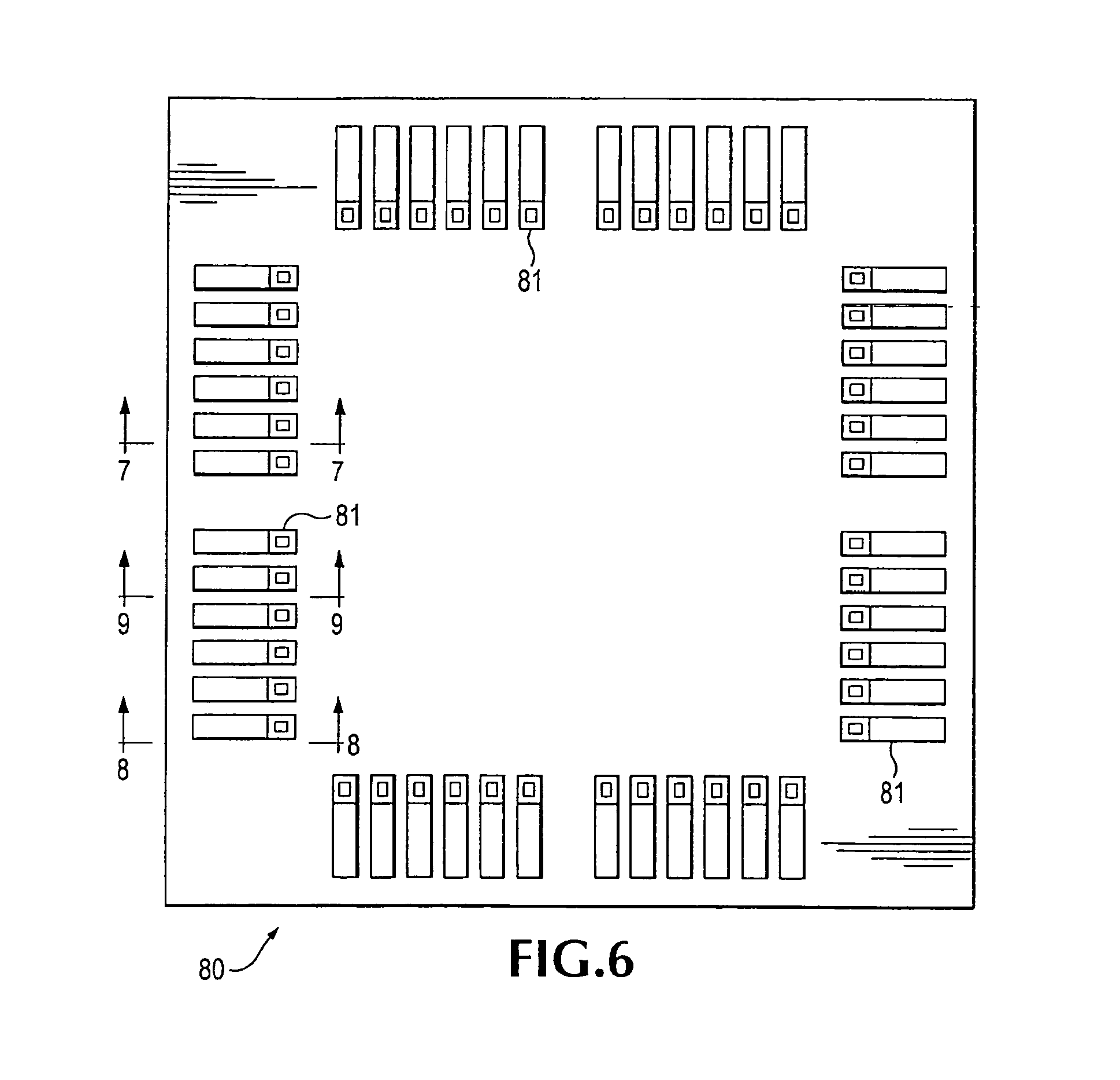
FIG. 6 is a bottom plan view of an exemplary coupon.
FIG. 7 is a sectional view of a membrane and coupon taken along line 7-7 of FIG. 6.
FIG. 8 is a sectional view of a membrane and coupon taken along line 8-8 of FIG. 6.
FIG. 9 is a sectional view of a membrane and coupon illustrating connection to a conductor extending through the forward support.
FIG. 10 is a sectional view of a membrane and coupon illustrating an alternative method of connecting a contact and a membrane supported trace.
FIG. 11 is a sectional view of a membrane and coupon illustrating an alternative method of connecting a contact and a membrane supported trace.
FIG. 12 is a sectional view of a coupon useful with a space transformer of a needle card-type probing apparatus.
FIG. 13 is a sectional view of additional embodiments of contacts for a coupon useful with a membrane probing device.
FIG. 14 is a bottom plan view of a multi-layered tile portion of a coupon.
FIG. 15 is a sectional view of the multi-layered tile of FIG. 14 taken along line 15-15.
FIG. 16 is a sectional view of the multi-layered tile of FIG. 14 taken along line 16-16.
FIG. 17 is a top view of a portion of an exemplary interface board and an impedance optimized co-axial cable to co-planar waveguide interface.
FIG. 18 is a sectional view of the exemplary co-axial cable to co-planar waveguide interface taken along line 18-18 of FIG. 17.
FIG. 19 is a top view of an alternative impedance optimized co-axial cable to co-planar waveguide interface.
DETAILED DESCRIPTION OF PREFERRED EMBODIMENTS
Referring in detail to the drawings where similar parts are identified by like reference numerals, and, more particularly to FIGS. 1 and 4, a probe head 40 for mounting a membrane probing assembly 42 is illustrated. In order to measure the electrical performance of the electrical circuit or device-under-test (DUT) of a particular die area 44 included on the silicon wafer 46, input and output ports of the test instrumentation 49 are communicatively connected to contacts 81 included on the lower portion of the membrane probing assembly and the chuck 51 which supports the wafer is moved in mutually perpendicular X, Y, and Z directions in order to bring bond pads of the DUT into pressing engagement with the probe's contacts.
The probe head 40 includes an interface board 52 on which traces 48 and shielded transmission lines are arranged for communicating data, signals and power between the test instrumentation and the DUT. Typically, high frequency signals are communicated between the test instrumentation and the probe with co-axial cables 53 which connect the instrumentation to co-axial cable adapters 55 on the interface board. The shielded transmission lines, typically comprising second lengths of co-axial cable 50 connect the adapters to metallic traces 87 on the interface board to transition the communication path from the coaxial cable to a co-planar waveguide. Referring also to FIG. 2, contact portions 86 that terminate conductors on surface of the membrane are arranged to overlap and conductively interconnect with the traces on the interface board extending the co-planar waveguide from the interface board to the lower surface of the membrane assembly in the vicinity of the contacts and, eventually, to appropriate contacts 81 of the probing apparatus.
Referring also to FIG. 3, the membrane probing assembly 42 includes a support element 54 formed of incompressible material such as a transparent, hard polymer. This element is detachably connected to the upper side of the interface board by means of four Allen screws 56 and corresponding nuts 58 (each screw passes through a respective attachment arm 60 of the support element, and a separate backing element 62 that evenly distributes the clamping pressure of the screws over the entire back side of the supporting element). This detachable connection enables different membrane assemblies having different arrangements of conductors to be quickly substituted for each other as needed for probing different devices. A transparent window 63 enables an operator of the probing apparatus to view the portion of the wafer in the vicinity of the probe contacts 81.
Referring to also FIG. 5, the support element 54 includes a rearward base portion 64 to which the attachment arms 60 are integrally joined. Also included on the support element 54 is a forward support or plunger 66 that projects outwardly from the flat base portion. This forward support has angled sides 68 that converge toward a flat support surface 70 so as to give the forward support the shape of a truncated pyramid. Referring also to FIG. 2, a flexible membrane assembly 72 is attached to the support after being aligned by means of alignment pins 74 included on the base portion. This flexible membrane assembly is formed by one or more plies of insulating sheeting such as KAPTON.TM. polyimide film sold by E. I. Du Pont de Nemours or other polyimide film, and flexible conductive layers or strips are provided on the surfaces of the plies or between the plies to form various conductors connecting the probe's contacts with the traces and shielded transmission lines on the interface board.
When the support element 54 is mounted on the upper side of the interface board 52 as shown in FIG. 3, the forward support 66 protrudes through a central opening 78 in the interface board so as to present the contacts 81 which are arranged on a coupon 80 that is attached to the surface of the membrane assembly 72 in a position suitable for pressing engagement with the pads of the DUT. Referring to FIG. 2, the membrane assembly includes radially extending arm segments 82 that are separated by inwardly curving edges 84 that give the assembly the shape of a formee cross, and these segments extend in an inclined manner along the angled sides 68 thereby clearing any upright components surrounding the pads. A series of contact pads 86 terminate the conductors of the membrane so that when the support element is mounted, these pads electrically engage corresponding termination pads provided on the upper side of the interface board so that the traces 48 and shielded transmission lines 50 on the interface board are conductively connected to the contacts 81 on the coupon 80.
The exemplary membrane probing assembly 42 is capable of probing a dense arrangement of contact pads over a large number of contact cycles in a manner that ensures reliable electrical connection between the contacts and pads during each cycle despite oxide buildup on the pads. This capability is a function of the construction and interconnection of the support element 54, the flexible membrane assembly 72 and the coupon 80. In particular, the membrane probing assembly is so constructed and connected to the support element to enable the contacts to engage a plurality of bond pads on the DUT even if the contact surfaces of the pads are not co-planar. Moreover, the contacts on the membrane assembly preferably wipe or scrub, in a locally controlled manner, laterally across the pads when brought into pressing engagement with the pads. Alternatively, the contacts may be constructed to enable the tips of the contacts to penetrate an oxide coating on the surfaces of the pads with substantially vertical motion. In the event that the contacts require replacement due to, for examples, a built up of pad material, wear, or a change in the arrangement of the pads to be probed, the contacts can be easily replaced by removing and replacing the coupon without the added expense of replacing the membrane assembly.
Referring also to FIGS. 7 and 8, for ease of illustration, an exemplary flexible membrane assembly 72 (indicated by a bracket) comprises one or more traces 76 affixed to an outer surface of a ply 92 comprising a dielectric material which is separated by a backplane conductive layer 94 from a second dielectric ply 96. However, additional dielectric plies and conductive layers can be used in accordance with conventional layering techniques. Preferably, the conductors of the backplane layer and the other traces are fabricated using a photolithographic process to enable precise control of the dimensions of the conductors. The membrane assembly is secured along its edges and extends over the flat support surface 70 of the plunger 66. Typically, the plurality of traces 76 affixed to the outer surface of, the membrane assembly provide communication paths for conducting data/signals and/or power from the conductors at the interface board to the surface of the membrane proximate the forward surface of the plunger. In conjunction with the backplane conductive layer, the conductive traces on the outer surface of the membrane assembly comprise controlled impedance communication structures connecting the interface board to the surface of the membrane in the vicinity of the forward surface of the plunger. The backplane conductive layer 94 may include portions defining one or more apertures which, in turn, define conductive strips of the backplane layer that are located proximate the various traces 76 on the outer surface of the membrane assembly. Filter capacitors 83 may be affixed to the membrane to provide frequency dependent interconnection between the conductive backplane layer and the power and signal conductors.
FIG. 8 shows an enlarged plan view of the lower surface of an exemplary coupon 80 that is attachable to the lower surface of the membrane 72 in area of the forward support surface 70 of the plunger. Typically, the coupon is attached to the surface of the membrane by an adhesive 95 that enables removal of the coupon by breaking the adhesive bond. The adhesive may be applied proximate the periphery of the coupon, at particular locations on the surface or as layer that substantially covers the surface of the coupon but which is displaced from the points of electrical contact by pressure applied to the lower surface of the coupon. The coupon includes a plurality of contacts 81 which in the illustrated exemplary embodiment are arranged in a square pattern suitable for engaging a square-like arrangement of bond pads. Referring also to FIGS. 7 and 8, which represent sectional views taken along lines 7-7 and 8-8, respectively, in FIG. 6, the coupon comprises an elastomeric layer 98 that is substantially co-extensive with the exposed surface of the portion of the membrane that covers the forward support surface 70 of the plunger. The elastomeric layer can be formed by a silicon rubber compound such as ELMER'S STICK-ALL.TM. silicon rubber made by the Borden Company or Sylgard 182 silicon rubber from Dow Corning Corporation. Each contact comprises a relatively thick rigid elongate beam 100, preferably 150 to 250 microns long, having an upper surface that is affixed to the elastomeric layer. At one end of the beam a contact tip 102 having the general shape of a truncated pyramid is formed. For wear resistance, the contact tip may include a tip end portion 104 comprising an alloy of rhodium and nickel. Proximate the end of the beam opposite of the contact tip and on the opposite side of the beam, a post portion 106 projects in the direction opposite of the contact tip. The post 106 projects through the elastomeric layer and, preferably, projects proud of the upper surface of the coupon. As illustrated in FIG. 7, the posts of selected contacts are arranged for conductive contact with one of the traces 76 on the outer surface of the membrane. As illustrated in FIG. 8, the posts of other contacts are arranged for conductive contact with contact buttons 108 projecting from the backplane conductive layer 94 through the lower ply 92 of the membrane assembly. Additional dielectric layers, for example layer 112, may be affixed to the lower surface of the elastic layer.
As indicated in FIG. 7, when an exemplary contact 102 is brought into pressing engagement with a respective bond pad 110, the contact force is exerted upward at the end of the beam to which the contact tip is affixed. However, the opposite end of the beam is constrained by the contact between the post 106 and the trace which is supported by the substantially incompressible membrane. The resulting off-center force on the rigid beam 100 causes the beam to pivot or tilt against the elastic recovery force exerted on the beam by the elastically supported lower surface of elastomeric layer 98. This tilting motion is localized in the sense that the portion of the beam proximate the tip moves a greater distance toward the forward support surface 70 than a rearward portion of the same beam. The effect is such as to cause the tip of the contact to translate across the pad in a lateral scrubbing movement with a solid-line and a dashed-line representing the beginning 102 and ending positions 102', respectively, of the contact tip on the pad 110 which, after displacement relative to the coupon, will be in position 110'. In this fashion, the insulating oxide buildup on the pad is abraded so as to provide reliable probe contact-to-bond pad electrical connections. On the other hand, the movement of the contact does not cause flexing of the trace or other conductor of the membrane which substantially reducing fatigue of the conductors and extending the service life of the membrane.
Referring to FIG. 9, the power transmissible on the traces deposited on the plies of the flexible membrane is limited by the cross-section of the traces. As a result, extremely wide traces or large numbers of traces may be required to provide sufficient power to operate the electrical circuits of a OUT or a plurality of DUTs. To increase the power available for testing single or multiple DUTs and reduce the number and size of traces on the membrane, the probing assembly 42 includes a power conductor 114 that is routed through the support 66 to a contact button 116 that extends through the lower wall of the forward support surface 70. The contact button conductively engages a buss 118, which may comprise a grid, On the upper surface of the membrane 72. At selected locations, the buss is extended downward to the lower surface of the membrane through apertures 119 in the other layers of the membrane. Selected contacts 81 include post portions that engage the buss extensions to provide power to the appropriate bond pad(s) of the DUT(s). The buss can have a substantially greater cross-section than the other conductors on the membrane because it is not located in an area of the membrane where flexibility is required.
The resilient elastomeric layer 98 of the coupon, backed by the incompressible support surface 70 and the substantially incompressible membrane 72, exerts a recovery force on each tilting beam contact and thus each contact tip to maintain an adequate level of contact tip-to-bond pad pressure during scrubbing. At the same time, the elastomeric layer accommodates minor height variations between the respective contacts and pads. Thus, when a relatively shorter contact is situated between an immediately adjacent pair of relatively taller contacts and these taller contacts are brought into engagement with their respective pads, deformation of the elastomeric layer enables the shorter contact to be brought into engagement with its pad after only a small amount of further over travel by the longer contact tips. Similarly, the compressibility of the elastomeric layer enables the contact tips to be brought into proper pressing engagement with a plurality of bond pads having surfaces that are not co-planar.
Referring to FIGS. 10 and 11, alternatively, the contacts 120 may comprise an elongate beam portion 122 affixed to the elastically supported lower surface of the elastomer layer 98. The contact tip portion 102 is affixed proximate one end of the beam portion. When the tip is brought into pressing engagement with the bond pad of the DUT, the lower surface of the elastomer layer is displaced proximate the end of the beam to which the tip is affixed, but the elastic force exerted at other end of the beam causes the beam to tilt facilitating the scrubbing action when the tip is pressed toward the bond pad of the DUT. The contact 120 is conductively connected to one of the traces 76 or the backplane layer 94 by a flexible conductive pigtail 124. The conductive pigtail may terminate on the surface of the elastomeric layer at a location suitable for contact with a trace 76 or a contact button 108 or may be conductively connected with a contact pad 126 suitably located on the surface of the coupon for contact with the appropriate trace or contact button.
FIG. 12 illustrates a coupon 150 (indicated by a bracket) having a plurality of elastomer suspended contacts that is suitable for use with components of a needle card-type probe head enabling the needle card-type probing assembly to be converted to a lower inductance probing assembly with elastically suspended contacts by removing the needle card-type probe head and replacing it with the coupon 150 that interfaces with a space transformer 152 (indicated with a bracket) of the needle card-type probing apparatus. In the schematic cross-sectional view of FIG. 12, the size of certain elements and components are exaggerated, for illustrative clarity. The interface board 154 of the needle card-type probing assembly is generally a conventional circuit board substrate having a plurality of terminals 156 (two of many shown) disposed on a surface thereof. The terminals provide an interface for wires 158 that connect instrumentation (not shown) to the probing assembly. As illustrated, the wires may be connected to terminals on one side of the interface board which are, in turn, connected by conductive vias 160 to terminals 162 or traces on the opposing side of the interface board. Additional components (not shown), such as active and passive electronic components, connectors, and the like, may be mounted on the interface board and connected to additional terminals. The interface board is typically round and commonly has a diameter on the order of 12 inches. The terminals 156, 162 on the interface board are often arranged at a 100 mil pitch or separation distance.
While some probing assemblies do not utilize an interposer, the exemplary probing assembly of FIG. 12 includes an interposer 164 (indicated by a bracket) disposed between the interface board and the space transformer. An interposer comprises interconnected electrical contacts disposed on opposing sides of a substrate so that components on opposing sides of the substrate can be conductively interconnected. An interposer is often used in a probing assembly to facilitate reliable conductive connection between the terminals of an interface board and the terminals of a space transformer. The interposer also aids in accommodating differences in thermal expansion of the interface board and the space transformer. The interposer 164 comprises a substrate 166 and a plurality of fuzz buttons 168 (two are shown) that protrude through holes in the substrate. The fuzz buttons each comprise a fine wire that is compressed into a small cylindrical shape to produce an electrically conductive, elastic wire mass. As a general proposition, the fuzz buttons are arranged at a pitch which matches that of the terminals 162 of the interface board. One end of each of the conductive fuzz buttons is in contact with a terminal on the interface board while the second end of the fuzz button is in contact with a terminal 170 on the space transformer. The elastic fuzz buttons are compressed providing compliance to accommodate variations in the separation distances between of the various terminals of the interface board and the space transformer and exerting pressure on the contacts to promote good conductivity.
The fuzz buttons protruding through the substrate of the interposer 164 contact conductive terminals 170 on one side of the space transformer 152. The space transformer 154 (indicated by a bracket) comprises a suitably circuited substrate 172, such as a multi-layer ceramic substrate having a plurality of terminals (contact areas, pads) 170 (two of many shown) disposed on the surface adjacent to the interposer and a plurality of terminals 174 (contact areas, pads) (two of many shown) disposed on the opposing surface. In the exemplary probing assembly, the contact pads adjacent the interposer are disposed at the pitch of the terminals of the interface board, and the contact pads 174 arranged on the opposing surface of the space transformer are disposed at a finer pitch corresponding to the pitch and arrangement of the needle-type probes included in the needle card with which the space transformer was intended to interface. While the pitch of the terminals of the interface board is commonly approximately 100 mil, the pitch of needle-type probes can be as fine as approximately 125 .mu.m. Conductive traces 176 in the multilayer substrate of the space transformer re-route the electrical connections from the finely pitched pattern required to interface with the probe head to the more coarsely pitched pattern that is obtainable with a printed circuit board, such as the interface board.
The various elements of the probing assembly are stacked and any suitable mechanism for stacking these components and ensuring reliable electrical contacts may be employed. As illustrated, the probing assembly includes a rigid front mounting plate 180 arranged on one side of the interface board. A stand-off 182 with a central aperture to receive the space transformer is attached to the front mounting plate. A mounting ring 184 which is preferably made of a springy material such as phosphor bronze and which may have a pattern of springy tabs extending therefrom, is attachable by screws 186 to the stand-off with the space transformer captured between the mounting ring and the stand-off.
A coupon 150 (indicated by a bracket) comprising an elastomeric layer 190 and a plurality of electrically conductive contacts is affixed to the face of the space transformer, preferably with an adhesive 191. The contacts, for example exemplary contact 192, may comprise, generally, a relatively thick, elongate, rigid beam portion 194 with a post portion 196 proximate one end of the beam and a contact tip 102 projecting in the opposite direction from the opposite side of the beam proximate the second end of the beam. Although other shapes and materials may be utilized, the contact tip preferably has the general shape of a truncated pyramid and the distal end of the contact tip may be coated with a layer of nickel and/or rhodium to provide good electrical conductivity and wear resistant when the contact tip is repeatedly pressed into engagement with the bond pads of DUTs. The post 196 has a rounded end distal of the beam that abuts a terminal 174 of the space transformer 152. The rounded end facilitates movable contact between the post and the terminal when the contact tip is displaced upward by interaction with a bond pad. Additional dielectric layer(s) 198 may be affixed to the lower surface of the elastomeric layer.
The contact 200 exemplifies a second type of contact that may included in the coupon. The contact 200 comprises a contact tip portion 202 which, preferably, has the shape of a truncated pyramid or cone and a body 204 with, preferably, a square or circular cross-section. A shoulder 206 may project from the body adjacent to the bottom surface of the elastomeric layer. The contact is conductively connected to the upper surface of the coupon 150 by a pig-tail 204 that is conductively attached to the body of the contact at one end and has a second end exposed at the upper surface of the coupon. The exposed portion of the pig-tail is arranged to contact a terminal 174 of the space transformer when the coupon is affixed to the surface of the transformer. Alternatively, a conductive connection between the contact and the terminal of the space transformer may incorporate a fuzz button, similar to fuzz button 168, that is embedded in the elastomeric layer with one end exposed at the surface of the coupon and the second end abutting the contact.
For better conductivity between a bond pad and the contact, the tip 202 of the contact 200 is intended to be pushed through the oxide layer that may develop on the surface of a bond pad and the elasticity of the elastomeric layer may be varied to aid penetration of the oxide layer. For example, the body 204 of the contact may be extended so as to directly contact the terminal of the space transformer, eliminating the need for the pigtail and enabling vertical movement of the contact in response to pressure from the pad to be limited to the deflection of the relatively rigid space transformer while the resiliency of the elastomeric layer may enable the contact to tilt if the surface of the pad is not parallel to the end surface of the tip of the contact. On the other hand, the elastomeric layer 190 may comprise a single layer with graduated resiliency or a plurality of sub-layers with differing resiliency to enable controlled vertical movement of the contact in response to the application of force at the tip of the contact. The coupon provides an economical way of converting a needle-type probing apparatus to a probing apparatus with much lower inductance. The relatively long, closely spaced, needle-like probes typically exhibit a single path inductance of 1-2 nano-Henrys (nH) which is sufficient to substantially distort high frequency signals and limit the usefulness of needle-type probes for testing devices with high frequency signals. On the other hand, single path inductance of 0.2 nH has been demonstrated with elastically suspended probes of membrane-type probing apparatuses.
Referring to FIG. 13, surface penetrating contacts 252, 254 can also be utilized in a coupon 250 (indicated by a bracket) suitable for use with a membrane probing apparatus. The contact 254 may be rigidly supported by the support 66 and the substantially incompressible membrane assembly 72. As illustrated, the body of the contact is extended through the elastomeric layer 98 so that it abuts the contact button 108 of the backplane layer 94. The abutting end of the contact is rounded enabling tilting of the contact, by compressing the elastomer surrounding the contact's body, to aid in aligning the end of the contact with a non-co-planar pad surface.
On the other hand, the body of the contact 252 terminates in the elastomeric layer and the contact can exhibit elastic behavior as determined by the properties of the elastomer layer. The elastomeric layer 98 may comprise sub-layers 98A and 98B, each having different elastic properties. The elasticity of the contact during vertical displacement may be determined by the properties of the sub-layer 98A which acts on a portion of the surface area of the upper end of the contact and the properties of sub-layer 98B which acts on the upper surface of a contact flange 253. A fuzz button 256 conductively connects the contact 252 with the trace 76.
Referring to FIGS. 14 and 15, a coupon 300 for use with a membrane probe or a space transformer may comprise a plurality of coupons or tiles 300a, 300b, 300c, 300d, each independently detachably affixed to a membrane or a space transformer enabling damaged or worn portions of the coupon to be independently replaced or portions of the coupon to include differing arrangements of contacts 81. Flexibility in arranging contacts and conductive connections to membranes and space transformers can be facilitated by layering the conductive and non-conductive elements of the coupon. For example, the tile 300c includes layered circuitry enabling conductive connection of thirteen finely pitched contact tips to a space transformer or membrane having six coarsely pitched contact pads enabling a typically less costly, more coarsely pitched space transformer or membrane to interface with the finely pitched contacts useful for probing small DUTs. The tile includes six grounded contact tips 302 including ground contact tips spaced to each side of a pair of high frequency signal contact tips 304 comprising the terminations of the conductors of a pair of ground-signal-ground (GSG) co-planar waveguides 310 (collectively indicated by a bracket). In addition, the exemplary tile includes a pair of contact tips 308 that are arranged to conduct DC power to a DUT and a pair of contact tips 306 that are arranged to conduct a lower frequency signal to the DUT. The contacts tips of the coupon are affixed to an elastically supported lower surface 314 of an elastomer layer 312. The coupon is affixed the lower surface to a space transformer 320 by adhesive 322.
The ground contact tips 302 are conductively connected to a conductive backplane layer 318 deposited between a pair of dielectric layers 320 and 321. The elastomeric layer is affixed to lower surface of the dielectric layer 321. The backplane layer extends over the area of the coupon that is occupied by the contact tips 302-308. The backplane layer is conductively connected to a suitable conductor in the space transformer by a contact button 324 on the upper surface of the coupon which is connected to the backplane layer by a via 326. The contact button 324 is arranged to engage a corresponding contact button on the lower surface of the space transformer. The contact tips 302 include post portions 327 in contact with backplane or a pigtail 328 that conductively connects the side of the beam portion of the contact tip and the back plane layer.
High frequency signals are transmitted between the test instrument and the DUT through the high frequency contact tips 304. Each of the high frequency contact tips is connected to one of a pair of contact buttons 330 on the upper surface of the coupon by a via 332 and a high frequency signal trace 324 that is deposited between the upper surface of the elastomeric layer 312 and the dielectric layer 321 which separates the high frequency trace from the backplane layer.
The contact tips 308 facilitating the transmission of DC power to the DUT are connected to an appropriate conductor 334 in the space transformer through a contact button 336 on the upper surface of the coupon. A trace 338, including portions that are conductively affixed to the lower surfaces of the beam portions of the power contact tips 308, is affixed to the lower surface of a dielectric layer 340 that is, in turn, affixed to the lower surface of the elastomer layer. A via 342 connects the power trace on the lower surface of the coupon to a contact button 344 on the upper surface of the coupon.
The coupon 300c also enables communication of a lower frequency AC signal to the DUT through contact tips 306 which include posts conductively engaging a lower frequency signal layer 346. The lower frequency signal is conducted from the lower frequency signal layer to the space transformer through a via 348 connecting the lower frequency signal layer with a low frequency signal contact button 350 on the upper surface of the coupon. A multilayered coupon such as the coupon 300 including the tile 300c provides flexibility for connecting an arrangement of finely pitched contact tips with the more coarsely pitched contacts of more moderately priced space transformers.
Referring to FIG. 16, the coupon 300 also includes one or more forming posts 370 that extend from the upper surface of the elastomer layer 312 to the lower surface of the elastomer layer. The forming posts aid in controlling the thickness and in maintaining the planarity of the surfaces of the elastomeric layer during the curing of the elastomer but are not conductively connected to a circuit of the probing apparatus. Posts 372, extending proud of the surfaces of the coupon are not arranged to conduct electricity but may be provided as an aid for the user in gauging the deflection of the elastically suspended contacts. For example, a post 372 having a first end in contact with the space transformer and a second end projecting from the bottom of the coupon a distance slightly less than the height of a contact tip may serve as a contact gage to prevent damage to the coupon from excess deflection of the elastically supported contact tips. Similarly, an elastically supported post 374 that projects below the lower surface of the coupon may be arranged to provide a signal of the limits of contact tip deflection. When the elastically suspended contact tip is pushed upward by engagement with the wafer, the end of the post contacts and conductively connects traces 376, 378 in the coupon to close an electrical circuit and provide a signal at a contact button 380 which may be connected to an indicator circuit.
At RF frequencies, signal frequencies in the radio frequency and microwave frequency ranges, it is important to match the impedance, typically 50.OMEGA., of the coaxial cable that typically interconnects the test instrumentation and the probing apparatus with the impedance of the coplanar waveguide that extends from the interface board 52 of the probing apparatus to the lower surface of the membrane in the area of the forward support surface 70. A mismatch of impedance will produce reflections of the signals which can couple to adjacent structures causing frequency dependent inaccuracies in the measurements of the DUT's performance. Referring to FIGS. 4 and 17, to transition the signal path from a coaxial cable 50 to the co-planar waveguide comprising traces on the membrane, the conductors of the coaxial cable are first conductively connected to respective traces 87 on the surface of the interface board which collectively comprise an interface board co-planar waveguide. Typically, the center conductor of the coaxial cable is connected to a center trace and the outer conductor of the cable, which is connected to a ground potential, is connected a pair of side traces, one spaced to either side of the center trace to form a ground-signal-ground (GSG) co-planar waveguide. The traces of the interface board co-planar waveguide terminate proximate the edge of the central opening 78 in the interface board and portions of the conductive traces on the membrane's lower surface are arranged to overlap portions of the surfaces of respective traces of the interface board co-planar waveguide when the membrane is clamped to the interface board. The overlapping surface portions conductively interconnect the traces of interface board waveguide to respective traces of a membrane waveguide extending the signal path to the lower surface of the membrane in the region proximate the forward support surface 70.
Typically, the interface board includes a sub-surface conductive layer that is connected to a ground potential to provide a ground plane for the interface board co-planar waveguide. However, inconsistency in the interconnection of the interface board co-planar waveguide and the ground plane may produce an impedance mismatch as the signal path transitions from coaxial cable to co-planar waveguide. The inventors realized that eliminating the interconnections with the interface board ground plane would eliminate this source of error but would also increase the impedance of the interface board co-planar waveguide to unacceptable levels. The inventors came to the unexpected conclusion that the interface board ground plane could be eliminated by decreasing the gaps between the signal trace and the ground traces of the coplanar waveguide, interconnecting the ground traces of adjacent waveguides and providing a low impedance structure for interconnecting the traces of the membrane and interface board waveguides.
The exemplary interface board 500 includes a plurality of conductive traces deposited on the upper surface. Three traces 502, 504, 506 comprise an interface board co-planar waveguide 508 (indicated by a bracket). The center conductor 510 of a coaxial cable 502 is conductively interconnected with the center trace 502 of the waveguide and the outer conductor 514 of the cable is connected to a first side trace 504 spaced apart from one edge of the center trace and a second side trace 506 spaced apart from the second edge of the center trace. Typically, a signal is communicated between the test instrumentation and the probing apparatus over the center conductor of the coaxial cable and the outer conductor is connected to a ground level electrical potential. The interface board ground plane 516, if any, terminates a substantial distance from the area of the interface board that is overlaid by the traces of the waveguide and is not electrically interconnected with the traces of the waveguide. To reduce the impedance of the "ungrounded" waveguide, the width of the center trace 502 differs from the widths of the side traces and the widths of the respective side traces may also differ from each other. For example, the center trace or signal conductor of an exemplary GSG waveguide having an impedance of 50.OMEGA. is 0.0179 inches wide and is separated from each of the spaced apart side traces of the waveguide by a gap of 0.004 inches. If a side trace, for example the side trace 506 of the exemplary waveguide is adjacent to the center traces of two waveguides, for example center trace 502 and the center trace 522 of a second waveguide 520 (indicated by a bracket), the side trace is shared by the adjacent waveguides 508, 512. The side trace preferably has a width of 0.029 inches and the outer conductors 514 of two adjacent coaxial cables 512, 526 are conductively connected to the trace. If a side trace, for example the side trace 504 of the exemplary interface board co-planar waveguide 508, is adjacent to only one center trace, the side trace has a width of 0.0107 inches.
Referring to also FIG. 19, while the impedance of a co-planar waveguide is substantially affected by the width of the gap between the traces of the waveguide, to improve the tolerance of the waveguide to misalignment between overlapping portions of the traces of the membrane waveguide and the traces of the interface board waveguide, the width of the center trace of the interface board waveguide may be narrowed for the portion of the length that is overlapped by the membrane trace. For example, the exemplary waveguide 600 includes a central trace 602 comprising a first length portion 604 that is preferably 0.0179 inches wide and a second length portion 606 which is overlapped by the membrane trace 614 and which is preferably 0.0159 inches wide. The gap 608 between the center trace and the side traces for the first length portion is 0.004 inches while the gap 610 for the second length portion is 0.005 inches increasing the tolerance to misalignment between the traces of interface and membrane waveguides. However, the impedance of the exemplary waveguide 600 is substantially the same as the impedance of a waveguide with uniform 0.004 inch gaps between traces.
The interconnection of the respective traces of the interface board waveguide and the corresponding traces of the membrane waveguide substantially effects the impedance of the waveguide. The electro-magnetic field is carried in the gap between the traces of a waveguide and the interconnection between the traces can produce a "pinch point" that substantially increases the waveguide's impedance. The inventors concluded that the more closely the geometry of the interconnecting structure resembles the geometry of the waveguide's traces the lower the impedance of the connection. Referring also to FIG. 18, when the membrane probe is assembled, contact portions 86 of the traces on the membrane overlap portions of the surfaces of the traces on the interface board. The inventors concluded that a signal path comprising a plurality of raised pads 540 on one of the overlapping surfaces of a pair of traces would facilitate a low impedance interconnection between the interface board waveguide and the membrane waveguide. The interconnecting structure for the center traces 502 and 530 of the interface board and membrane waveguides, respectively, comprises four pads 540 that project from the surface of one the traces into contact with the surface of the other trace. A pair of the raised pads, indicated generally as 542 and 544, is arranged substantially parallel to each of the edges of the center trace on which the pads are affixed and the pads are located as close to the edge of the trace as tolerance for misalignment of the trace will allow. Preferably, a raised pad is located at each of the corners of a substantially rectangular area on the surface of the trace.
Similarly, a portion of the side trace 534 on the membrane overlaps a portion of the side trace 504 on the surface of the interface board 500 and a portion of the membrane side trace 532 overlaps a portion of the interface board waveguide side trace 506. On the side (ground) traces, the pair 546 of raised pads 540 nearest the center trace 502 are located as close to the inner edge of the trace as is permitted by the tolerance to misalignment and the second pair 548 of raised pads are preferably located nearer the center line of the membrane trace than the second edge of the trace. The electro-magnetic field is carried in the region between the traces of the waveguide and locating the pads of interconnecting structure closer to the region in which the electro-magnetic field is confined reduces the inductance of the connection.
The accuracy of measurements performed with the membrane probing apparatus, particularly at frequencies in the radio and microwave frequency ranges, is improved by optimizing the impedance of the interface between co-axial cables, interconnecting the test instrumentation and the probing apparatus, and the co-planar waveguide that extends the signal path to the contact tips. A longer service life and lower operating cost for a membrane probing apparatus is achievable by including the contact tips on an elastic coupon that is attachable to a membrane that includes a plurality of traces over which signals, data and power can be transmitted. Replacing the probe needles of a needle type probing apparatus with a coupon attachable to a space transformer and including elastically supported contact tips can also improve the performance of a needle-type probing apparatus by substantially lower the inductance of the apparatus.
The detailed description, above, sets forth numerous specific details to provide a thorough understanding of the present invention. However, those skilled in the art will appreciate that the present invention may be practiced without these specific details. In other instances, well known methods, procedures, components, and circuitry have not been described in detail to avoid obscuring the present invention.
All the references cited herein are incorporated by reference.
The terms and expressions that have been employed in the foregoing specification are used as terms of description and not of limitation, and there is no intention, in the use of such terms and expressions, of excluding equivalents of the features shown and described or portions thereof, it being recognized that the scope of the invention is defined and limited only by the claims that follow.
* * * * *
References
D00000
D00001
D00002
D00003
D00004
D00005
D00006
D00007
D00008
D00009
D00010
D00011
XML
uspto.report is an independent third-party trademark research tool that is not affiliated, endorsed, or sponsored by the United States Patent and Trademark Office (USPTO) or any other governmental organization. The information provided by uspto.report is based on publicly available data at the time of writing and is intended for informational purposes only.
While we strive to provide accurate and up-to-date information, we do not guarantee the accuracy, completeness, reliability, or suitability of the information displayed on this site. The use of this site is at your own risk. Any reliance you place on such information is therefore strictly at your own risk.
All official trademark data, including owner information, should be verified by visiting the official USPTO website at www.uspto.gov. This site is not intended to replace professional legal advice and should not be used as a substitute for consulting with a legal professional who is knowledgeable about trademark law.