Retractable blade for lead removal device
Grace , et al.
U.S. patent number 10,219,819 [Application Number 15/498,165] was granted by the patent office on 2019-03-05 for retractable blade for lead removal device. This patent grant is currently assigned to The Spectranetics Corporation. The grantee listed for this patent is The Spectranetics Corporation. Invention is credited to Dustin L. Grace, Kenneth P. Grace.


View All Diagrams
| United States Patent | 10,219,819 |
| Grace , et al. | March 5, 2019 |
Retractable blade for lead removal device
Abstract
Methods and devices for separating an implanted object, such as a pacemaker lead, from tissue surrounding such object in a patient's vasculature system. Specifically, the tissue separating device includes a handle, an elongate sheath and a circular cutting blade that may extend from the distal end of the sheath upon actuating the handle. The circular cutting blade is configured to engage the tissue surrounding an implanted lead and cut such tissue in a coring fashion as the device translates along the length of the lead, thereby allowing the lead, as well as any tissue remaining attached to the lead, to enter the device's elongate shaft. The tissue separating device includes a cam mechanism at the distal portion of the sheath that allows the user of the device to more accurately control the extension and rotation of the cutting blade upon being actuated by the handle.
| Inventors: | Grace; Dustin L. (San Carlos, CA), Grace; Kenneth P. (Woodland Park, CO) | ||||||||||
|---|---|---|---|---|---|---|---|---|---|---|---|
| Applicant: |
|
||||||||||
| Assignee: | The Spectranetics Corporation
(Colorado Springs, CO) |
||||||||||
| Family ID: | 51531062 | ||||||||||
| Appl. No.: | 15/498,165 | ||||||||||
| Filed: | April 26, 2017 |
Prior Publication Data
| Document Identifier | Publication Date | |
|---|---|---|
| US 20170224373 A1 | Aug 10, 2017 | |
Related U.S. Patent Documents
| Application Number | Filing Date | Patent Number | Issue Date | ||
|---|---|---|---|---|---|
| 13834405 | Mar 15, 2013 | 9668765 | |||
| Current U.S. Class: | 1/1 |
| Current CPC Class: | A61B 17/32053 (20130101); A61N 1/057 (20130101); A61B 17/320016 (20130101); A61B 2017/00305 (20130101); A61N 2001/0578 (20130101) |
| Current International Class: | A61B 17/32 (20060101); A61N 1/05 (20060101); A61B 17/3205 (20060101); A61B 17/00 (20060101) |
References Cited [Referenced By]
U.S. Patent Documents
| 1663761 | March 1928 | Johnson |
| 2708437 | May 1955 | Hutchins |
| 3400708 | September 1968 | Scheidt |
| 3614953 | October 1971 | Moss |
| 3703767 | November 1972 | Masseran |
| 3756242 | September 1973 | Coss |
| 4051596 | October 1977 | Hofmann |
| 4203444 | May 1980 | Bonnell et al. |
| 4246902 | January 1981 | Martinez |
| 4274414 | June 1981 | Johnson et al. |
| D267145 | December 1982 | Kaneko |
| 4471777 | September 1984 | McCorkle, Jr. |
| 4517977 | May 1985 | Frost |
| 4582056 | April 1986 | McCorkle et al. |
| 4598710 | July 1986 | Kleinberg et al. |
| 4601290 | July 1986 | Effron et al. |
| 4646738 | March 1987 | Trott |
| 4662869 | May 1987 | Wright |
| 4674502 | June 1987 | Imonti |
| 4729763 | March 1988 | Henrie |
| 4754755 | July 1988 | Husted |
| 4767403 | August 1988 | Hodge |
| 4785826 | November 1988 | Ward |
| D309350 | July 1990 | Sutherland et al. |
| 4943289 | July 1990 | Goode et al. |
| 4950277 | August 1990 | Farr |
| 4988347 | January 1991 | Goode et al. |
| 5011482 | April 1991 | Goode et al. |
| 5013310 | May 1991 | Goode et al. |
| 5031634 | July 1991 | Simon |
| 5152744 | October 1992 | Krause et al. |
| 5201316 | April 1993 | Pomeranz et al. |
| 5207683 | May 1993 | Goode et al. |
| 5217454 | June 1993 | Khoury |
| 5261877 | November 1993 | Fine et al. |
| 5263928 | November 1993 | Trauthen et al. |
| 5275609 | January 1994 | Pingleton et al. |
| 5281220 | January 1994 | Blake et al. |
| 5290275 | March 1994 | Kittrell et al. |
| 5290303 | March 1994 | Pingleton et al. |
| 5383199 | January 1995 | Laudenslager et al. |
| 5395328 | March 1995 | Ockuly et al. |
| 5411513 | May 1995 | Ireland et al. |
| 5423330 | June 1995 | Lee |
| 5456680 | October 1995 | Taylor et al. |
| 5484433 | January 1996 | Taylor et al. |
| 5507751 | April 1996 | Goode et al. |
| 5562694 | October 1996 | Sauer et al. |
| 5569284 | October 1996 | Young et al. |
| 5575797 | November 1996 | Neubauer et al. |
| 5595186 | January 1997 | Rubinstein et al. |
| 5620451 | April 1997 | Rosborough |
| 5632749 | May 1997 | Goode et al. |
| 5697936 | December 1997 | Shipko et al. |
| 5718237 | February 1998 | Haaga |
| 5725523 | March 1998 | Mueller |
| 5766164 | June 1998 | Mueller et al. |
| 5782823 | July 1998 | Mueller |
| 5792151 | August 1998 | Heck et al. |
| 5807399 | September 1998 | Laske et al. |
| 5814044 | September 1998 | Hooven |
| 5823971 | October 1998 | Robinson et al. |
| 5824026 | October 1998 | Diaz |
| 5863294 | January 1999 | Alden |
| 5873886 | February 1999 | Larsen et al. |
| 5879365 | March 1999 | Whitfield et al. |
| 5893862 | April 1999 | Pratt et al. |
| 5899915 | May 1999 | Saadat |
| 5910150 | June 1999 | Saadat |
| 5916210 | June 1999 | Winston |
| 5931848 | August 1999 | Saadat |
| 5941893 | August 1999 | Saadat |
| 5951581 | September 1999 | Saadat et al. |
| 5972012 | October 1999 | Ream et al. |
| 5980515 | November 1999 | Tu |
| 6007512 | December 1999 | Hooven |
| 6010476 | January 2000 | Saadat |
| 6019756 | February 2000 | Mueller et al. |
| 6022336 | February 2000 | Zadno-Azizi et al. |
| 6027497 | February 2000 | Daniel et al. |
| 6033402 | March 2000 | Tu et al. |
| 6036685 | March 2000 | Mueller |
| 6039748 | March 2000 | Savage et al. |
| 6051008 | April 2000 | Saadat et al. |
| 6063037 | May 2000 | Mittermeier et al. |
| 6066131 | May 2000 | Mueller et al. |
| 6080175 | June 2000 | Hogendijk |
| 6083237 | July 2000 | Huitema et al. |
| 6099537 | August 2000 | Sugai et al. |
| 6102926 | August 2000 | Tartaglia et al. |
| D430781 | September 2000 | Hillegonds |
| 6117149 | September 2000 | Sorensen et al. |
| 6120520 | September 2000 | Saadat et al. |
| 6126654 | October 2000 | Giba et al. |
| 6136005 | October 2000 | Goode et al. |
| 6139543 | October 2000 | Esch et al. |
| 6152909 | November 2000 | Bagaoisan et al. |
| 6152918 | November 2000 | Padilla et al. |
| 6156049 | December 2000 | Lovato et al. |
| 6159203 | December 2000 | Sinofsky |
| 6159225 | December 2000 | Makower |
| 6162214 | December 2000 | Mueller et al. |
| 6165188 | December 2000 | Saadat et al. |
| 6167315 | December 2000 | Coe et al. |
| 6174307 | January 2001 | Daniel et al. |
| 6190352 | February 2001 | Haarala et al. |
| 6190353 | February 2001 | Makower et al. |
| 6203537 | March 2001 | Adrian |
| 6210400 | April 2001 | Hebert et al. |
| 6228076 | May 2001 | Winston et al. |
| 6235044 | May 2001 | Root et al. |
| 6241692 | June 2001 | Tu et al. |
| 6245011 | June 2001 | Dudda et al. |
| 6251121 | June 2001 | Saadat |
| 6258083 | July 2001 | Daniel et al. |
| 6290668 | September 2001 | Gregory et al. |
| 6315774 | November 2001 | Daniel et al. |
| 6324434 | November 2001 | Coe et al. |
| 6379351 | April 2002 | Thapliyal et al. |
| 6395002 | May 2002 | Ellman et al. |
| 6398773 | June 2002 | Bagaoisan et al. |
| 6402771 | June 2002 | Palmer et al. |
| 6402781 | June 2002 | Langberg et al. |
| 6419674 | July 2002 | Bowser et al. |
| 6419684 | July 2002 | Heisler et al. |
| 6423051 | July 2002 | Kaplan et al. |
| 6428539 | August 2002 | Baxter et al. |
| 6428556 | August 2002 | Chin |
| 6432119 | August 2002 | Saadat |
| 6436054 | August 2002 | Viola et al. |
| 6436114 | August 2002 | Novak et al. |
| 6454741 | September 2002 | Muni et al. |
| 6454758 | September 2002 | Thompson et al. |
| 6461349 | October 2002 | Elbrecht et al. |
| 6478777 | November 2002 | Honeck et al. |
| 6488636 | December 2002 | Bryan et al. |
| 6500182 | December 2002 | Foster |
| 6512959 | January 2003 | Gomperz et al. |
| 6527752 | March 2003 | Bosley et al. |
| 6537314 | March 2003 | Langberg et al. |
| 6540865 | April 2003 | Miekka et al. |
| 6554779 | April 2003 | Viola et al. |
| 6558382 | May 2003 | Jahns et al. |
| 6565588 | May 2003 | Clement et al. |
| 6569082 | May 2003 | Chin |
| 6575997 | June 2003 | Palmer et al. |
| 6592607 | July 2003 | Palmer et al. |
| 6595982 | July 2003 | Sekino et al. |
| 6599296 | July 2003 | Gillick et al. |
| 6602241 | August 2003 | Makower et al. |
| 6607547 | August 2003 | Chin |
| 6610046 | August 2003 | Usami et al. |
| 6613013 | September 2003 | Haarala et al. |
| 6620153 | September 2003 | Mueller et al. |
| 6620160 | September 2003 | Lewis et al. |
| 6620180 | September 2003 | Bays et al. |
| 6641590 | November 2003 | Palmer et al. |
| 6652480 | November 2003 | Imran et al. |
| 6652548 | November 2003 | Evans et al. |
| 6660021 | December 2003 | Palmer et al. |
| 6663626 | December 2003 | Truckai et al. |
| 6669685 | December 2003 | Rizoiu et al. |
| 6673090 | January 2004 | Root et al. |
| 6687548 | February 2004 | Goode |
| 6702813 | March 2004 | Baxter et al. |
| 6706018 | March 2004 | Westlund et al. |
| 6706052 | March 2004 | Chin |
| 6706065 | March 2004 | Langberg et al. |
| 6709456 | March 2004 | Langberg et al. |
| 6712773 | March 2004 | Viola |
| 6712826 | March 2004 | Lui |
| 6772014 | August 2004 | Coe et al. |
| 6802838 | October 2004 | Loeb et al. |
| 6805692 | October 2004 | Muni et al. |
| 6810882 | November 2004 | Langberg et al. |
| 6818001 | November 2004 | Wulfman et al. |
| 6860860 | March 2005 | Viola |
| 6871085 | March 2005 | Sommer |
| 6884240 | April 2005 | Dykes |
| 6887238 | May 2005 | Jahns et al. |
| 6893450 | May 2005 | Foster |
| 6913612 | July 2005 | Palmer et al. |
| 6962585 | November 2005 | Poleo et al. |
| 6979290 | December 2005 | Mourlas et al. |
| 6979319 | December 2005 | Manning et al. |
| 6989028 | January 2006 | Lashinski et al. |
| 6999809 | February 2006 | Currier et al. |
| 7004956 | February 2006 | Palmer et al. |
| 7011682 | March 2006 | Lashinski et al. |
| 7014614 | March 2006 | Casula |
| 7022133 | April 2006 | Yee et al. |
| 7033324 | April 2006 | Giusti et al. |
| 7033335 | April 2006 | Haarala et al. |
| 7033344 | April 2006 | Imran |
| 7033357 | April 2006 | Baxter et al. |
| 7060061 | June 2006 | Altshuler et al. |
| 7063693 | June 2006 | Guenst |
| 7077856 | July 2006 | Whitman |
| 7092765 | August 2006 | Geske et al. |
| 7104983 | September 2006 | Grasso et al. |
| 7114642 | October 2006 | Whitman |
| 7117039 | October 2006 | Manning et al. |
| 7149587 | December 2006 | Wardle et al. |
| 7151965 | December 2006 | Osypka |
| 7189207 | March 2007 | Viola |
| 7191015 | March 2007 | Lamson et al. |
| 7192430 | March 2007 | Truckai et al. |
| 7204824 | April 2007 | Moulis |
| 7214180 | May 2007 | Chin |
| 7226459 | June 2007 | Cesarini et al. |
| 7238179 | July 2007 | Brucker et al. |
| 7238180 | July 2007 | Mester et al. |
| 7252641 | August 2007 | Thompson et al. |
| 7264587 | September 2007 | Chin |
| 7273478 | September 2007 | Appling et al. |
| 7276052 | October 2007 | Kobayashi et al. |
| 7288096 | October 2007 | Chin |
| 7296577 | November 2007 | Lashinski et al. |
| 7306588 | December 2007 | Loeb et al. |
| 7326226 | February 2008 | Root et al. |
| 7328071 | February 2008 | Stehr et al. |
| 7344546 | March 2008 | Wulfman et al. |
| 7357794 | April 2008 | Makower et al. |
| 7359756 | April 2008 | Goode |
| 7369901 | May 2008 | Morgan et al. |
| 7396354 | July 2008 | Rychnovsky et al. |
| 7398781 | July 2008 | Chin |
| 7449010 | November 2008 | Hayase et al. |
| 7462167 | December 2008 | Kratz et al. |
| 7485127 | February 2009 | Nistal |
| 7494484 | February 2009 | Beck et al. |
| 7507252 | March 2009 | Lashinski et al. |
| 7509169 | March 2009 | Eigler et al. |
| 7510576 | March 2009 | Langberg et al. |
| 7513877 | April 2009 | Viola |
| 7513892 | April 2009 | Haarala et al. |
| 7526342 | April 2009 | Chin et al. |
| 7537602 | May 2009 | Whitman |
| D594983 | June 2009 | Price et al. |
| 7540865 | June 2009 | Griffin et al. |
| 7544197 | June 2009 | Kelsch et al. |
| 7559941 | July 2009 | Zannis et al. |
| D600792 | September 2009 | Eubanks et al. |
| 7591790 | September 2009 | Pflueger |
| 7597698 | October 2009 | Chin |
| 7606615 | October 2009 | Makower et al. |
| 7611474 | November 2009 | Hibner et al. |
| 7637904 | December 2009 | Wingler et al. |
| 7645286 | January 2010 | Catanese et al. |
| 7648466 | January 2010 | Stephens et al. |
| 7651503 | January 2010 | Coe et al. |
| 7651504 | January 2010 | Goode et al. |
| D610259 | February 2010 | Way et al. |
| D611146 | March 2010 | Way et al. |
| 7674272 | March 2010 | Torrance et al. |
| 7695485 | April 2010 | Whitman et al. |
| 7695512 | April 2010 | Lashinski et al. |
| 7697996 | April 2010 | Manning et al. |
| 7713231 | May 2010 | Wulfman et al. |
| 7713235 | May 2010 | Torrance et al. |
| 7713281 | May 2010 | Leeflang et al. |
| 7722549 | May 2010 | Nakao |
| 7740626 | June 2010 | Takayama et al. |
| 7743960 | June 2010 | Whitman et al. |
| D619252 | July 2010 | Way et al. |
| D619253 | July 2010 | Way et al. |
| 7758594 | July 2010 | Lamson et al. |
| 7758613 | July 2010 | Whitman |
| D621939 | August 2010 | Way et al. |
| 7766923 | August 2010 | Catanese et al. |
| 7780682 | August 2010 | Catanese et al. |
| 7780694 | August 2010 | Palmer et al. |
| 7794411 | September 2010 | Ritchart et al. |
| 7798813 | September 2010 | Harrel |
| 7803151 | September 2010 | Whitman |
| 7806835 | October 2010 | Hibner et al. |
| 7811281 | October 2010 | Rentrop |
| 7815655 | October 2010 | Catanese et al. |
| 7842009 | November 2010 | Torrance et al. |
| 7845538 | December 2010 | Whitman |
| 7858038 | December 2010 | Andreyko et al. |
| D631155 | January 2011 | Peine et al. |
| 7875018 | January 2011 | Tockman et al. |
| 7875049 | January 2011 | Eversull et al. |
| D631965 | February 2011 | Price et al. |
| 7890186 | February 2011 | Wardle et al. |
| 7890192 | February 2011 | Kelsch et al. |
| 7896879 | March 2011 | Solsberg et al. |
| 7896891 | March 2011 | Catanese et al. |
| 7905889 | March 2011 | Catanese et al. |
| 7909836 | March 2011 | McLean et al. |
| 7914464 | March 2011 | Burdorff et al. |
| 7914542 | March 2011 | Lamson et al. |
| D635671 | April 2011 | Way et al. |
| 7918230 | April 2011 | Whitman et al. |
| 7918803 | April 2011 | Ritchart et al. |
| 7930040 | April 2011 | Kelsch et al. |
| D638935 | May 2011 | Gilmore et al. |
| 7935146 | May 2011 | Langberg et al. |
| 7938786 | May 2011 | Ritchie et al. |
| 7942830 | May 2011 | Solsberg et al. |
| 7951071 | May 2011 | Whitman et al. |
| 7951158 | May 2011 | Catanese et al. |
| 7963040 | June 2011 | Shan et al. |
| 7963433 | June 2011 | Whitman et al. |
| 7974710 | July 2011 | Seifert |
| 7981049 | July 2011 | Ritchie et al. |
| 7981050 | July 2011 | Ritchart et al. |
| 7981128 | July 2011 | To et al. |
| 7988726 | August 2011 | Langberg et al. |
| 7991258 | August 2011 | Temelkuran et al. |
| 7992758 | August 2011 | Whitman et al. |
| 7993350 | August 2011 | Ventura et al. |
| 7993351 | August 2011 | Worley et al. |
| 7993359 | August 2011 | Atwell et al. |
| 8007434 | August 2011 | Olson |
| 8007469 | August 2011 | Duffy |
| 8007488 | August 2011 | Ravenscroft |
| 8007503 | August 2011 | Catanese et al. |
| 8007506 | August 2011 | To et al. |
| 8016748 | September 2011 | Mourlas et al. |
| 8016844 | September 2011 | Privitera et al. |
| 8016855 | September 2011 | Whitman et al. |
| 8016858 | September 2011 | Whitman |
| 8021373 | September 2011 | Whitman et al. |
| 8025199 | September 2011 | Whitman et al. |
| 8043309 | October 2011 | Catanese et al. |
| RE42959 | November 2011 | Saadat et al. |
| 8052616 | November 2011 | Andrisek et al. |
| 8052659 | November 2011 | Ravenscroft et al. |
| 8056786 | November 2011 | Whitman et al. |
| 8056791 | November 2011 | Whitman |
| D650074 | December 2011 | Hunt et al. |
| 8070762 | December 2011 | Escudero et al. |
| 8090430 | January 2012 | Makower et al. |
| 8097012 | January 2012 | Kagarise |
| 8100920 | January 2012 | Gambale et al. |
| 8118208 | February 2012 | Whitman |
| 8126570 | February 2012 | Manning et al. |
| 8128577 | March 2012 | Viola |
| 8128636 | March 2012 | Lui et al. |
| 8133214 | March 2012 | Hayase et al. |
| 8137377 | March 2012 | Palmer et al. |
| 8142442 | March 2012 | Palmer et al. |
| 8142446 | March 2012 | Shan |
| RE43300 | April 2012 | Saadat et al. |
| 8157815 | April 2012 | Catanese et al. |
| 8186559 | May 2012 | Whitman |
| 8187204 | May 2012 | Miller et al. |
| 8192430 | June 2012 | Goode et al. |
| 8202229 | June 2012 | Miller et al. |
| 8206409 | June 2012 | Privitera et al. |
| 8211118 | July 2012 | Catanese et al. |
| 8216254 | July 2012 | McLean et al. |
| 8235916 | August 2012 | Whiting et al. |
| 8236016 | August 2012 | To et al. |
| 8239039 | August 2012 | Zarembo et al. |
| 8241272 | August 2012 | Arnold et al. |
| 8251916 | August 2012 | Speeg et al. |
| 8252015 | August 2012 | Leeflang et al. |
| 8257312 | September 2012 | Duffy |
| 8272554 | September 2012 | Whitman et al. |
| 8273078 | September 2012 | Muenker |
| 8295947 | October 2012 | Lamson et al. |
| 8303511 | November 2012 | Eigler et al. |
| 8303570 | November 2012 | Gregorich et al. |
| 8323240 | December 2012 | Wulfman et al. |
| 8326437 | December 2012 | Cully et al. |
| 8333740 | December 2012 | Shippert |
| 8333776 | December 2012 | Cheng et al. |
| 8337516 | December 2012 | Escudero et al. |
| 8343167 | January 2013 | Henson |
| 8343187 | January 2013 | Lamson et al. |
| 8353899 | January 2013 | Wells et al. |
| 8361094 | January 2013 | To et al. |
| 8364280 | January 2013 | Marnfeldt et al. |
| 8372098 | February 2013 | Tran |
| D679010 | March 2013 | Kitayama et al. |
| 8394110 | March 2013 | Catanese et al. |
| 8394113 | March 2013 | Wei et al. |
| 8424535 | April 2013 | Hessler et al. |
| 8425535 | April 2013 | McLean et al. |
| D687549 | August 2013 | Johnson et al. |
| D697618 | January 2014 | Gonzales et al. |
| 8622275 | January 2014 | Baxter et al. |
| D706928 | June 2014 | Harrison et al. |
| D708742 | July 2014 | Dallemagne et al. |
| 8961551 | February 2015 | Taylor |
| 9232945 | January 2016 | Zingman |
| 9283040 | March 2016 | Hendrick et al. |
| D765243 | August 2016 | Halbert |
| 9622762 | April 2017 | Dahm et al. |
| D786430 | May 2017 | Davies et al. |
| 9668765 | June 2017 | Grace et al. |
| 9808275 | November 2017 | Taylor |
| 9918737 | March 2018 | Carver et al. |
| 9925366 | March 2018 | Grace et al. |
| 2001/0005789 | June 2001 | Root et al. |
| 2001/0016717 | August 2001 | Haarala et al. |
| 2001/0025174 | September 2001 | Daniel et al. |
| 2001/0031981 | October 2001 | Evans et al. |
| 2001/0039427 | November 2001 | Dinger et al. |
| 2001/0041899 | November 2001 | Foster |
| 2001/0044568 | November 2001 | Langberg et al. |
| 2002/0002372 | January 2002 | Jahns et al. |
| 2002/0007204 | January 2002 | Goode |
| 2002/0010475 | January 2002 | Lui |
| 2002/0010487 | January 2002 | Evans et al. |
| 2002/0016628 | February 2002 | Langberg et al. |
| 2002/0045811 | April 2002 | Kittrell et al. |
| 2002/0065543 | May 2002 | Gomperz et al. |
| 2002/0068954 | June 2002 | Foster |
| 2002/0087046 | July 2002 | Sullivan et al. |
| 2002/0087151 | July 2002 | Mody et al. |
| 2002/0103459 | August 2002 | Sparks et al. |
| 2002/0103477 | August 2002 | Grasso et al. |
| 2002/0103532 | August 2002 | Langberg et al. |
| 2002/0103533 | August 2002 | Langberg et al. |
| 2002/0123785 | September 2002 | Zhang et al. |
| 2002/0151918 | October 2002 | Lafontaine et al. |
| 2002/0151961 | October 2002 | Lashinski et al. |
| 2002/0165425 | November 2002 | Yoon et al. |
| 2002/0183735 | December 2002 | Edwards et al. |
| 2002/0188278 | December 2002 | Tockman et al. |
| 2003/0009146 | January 2003 | Muni et al. |
| 2003/0036788 | February 2003 | Coe et al. |
| 2003/0050630 | March 2003 | Mody et al. |
| 2003/0050631 | March 2003 | Mody et al. |
| 2003/0055444 | March 2003 | Evans et al. |
| 2003/0055445 | March 2003 | Evans et al. |
| 2003/0069575 | April 2003 | Chin et al. |
| 2003/0073985 | April 2003 | Mueller et al. |
| 2003/0078562 | April 2003 | Makower et al. |
| 2003/0105451 | June 2003 | Westlund et al. |
| 2003/0125619 | July 2003 | Manning et al. |
| 2003/0125709 | July 2003 | Eidenschink |
| 2003/0167056 | September 2003 | Jahns et al. |
| 2003/0187460 | October 2003 | Chin et al. |
| 2003/0187461 | October 2003 | Chin |
| 2003/0199916 | October 2003 | Yee et al. |
| 2003/0199921 | October 2003 | Palmer et al. |
| 2003/0204202 | October 2003 | Palmer et al. |
| 2003/0208209 | November 2003 | Gambale et al. |
| 2003/0229323 | December 2003 | Haarala et al. |
| 2003/0229353 | December 2003 | Cragg |
| 2004/0006358 | January 2004 | Wulfman et al. |
| 2004/0010248 | January 2004 | Appling et al. |
| 2004/0015193 | January 2004 | Lamson et al. |
| 2004/0019359 | January 2004 | Worley et al. |
| 2004/0049208 | March 2004 | Hill et al. |
| 2004/0054368 | March 2004 | Truckai et al. |
| 2004/0054388 | March 2004 | Osypka |
| 2004/0059348 | March 2004 | Geske et al. |
| 2004/0064024 | April 2004 | Sommer |
| 2004/0068256 | April 2004 | Rizoiu et al. |
| 2004/0068288 | April 2004 | Palmer et al. |
| 2004/0093016 | May 2004 | Root et al. |
| 2004/0102804 | May 2004 | Chin |
| 2004/0102841 | May 2004 | Langberg et al. |
| 2004/0111101 | June 2004 | Chin |
| 2004/0116939 | June 2004 | Goode |
| 2004/0133220 | July 2004 | Lashinski et al. |
| 2004/0138562 | July 2004 | Makower et al. |
| 2004/0138744 | July 2004 | Lashinski et al. |
| 2004/0143284 | July 2004 | Chin |
| 2004/0147911 | July 2004 | Sinofsky |
| 2004/0147912 | July 2004 | Sinofsky |
| 2004/0147913 | July 2004 | Sinofsky |
| 2004/0153096 | August 2004 | Goode et al. |
| 2004/0153098 | August 2004 | Chin et al. |
| 2004/0172116 | September 2004 | Seifert et al. |
| 2004/0176840 | September 2004 | Langberg et al. |
| 2004/0181249 | September 2004 | Torrance et al. |
| 2004/0216748 | November 2004 | Chin |
| 2004/0220519 | November 2004 | Wulfman et al. |
| 2004/0230212 | November 2004 | Wulfman |
| 2004/0230213 | November 2004 | Wulfman et al. |
| 2004/0235611 | November 2004 | Nistal |
| 2004/0236312 | November 2004 | Nistal et al. |
| 2004/0236397 | November 2004 | Coe et al. |
| 2004/0243123 | December 2004 | Grasso et al. |
| 2004/0243162 | December 2004 | Wulfman et al. |
| 2004/0254534 | December 2004 | Bjorkman et al. |
| 2004/0260322 | December 2004 | Rudko et al. |
| 2004/0267276 | December 2004 | Camino et al. |
| 2004/0267304 | December 2004 | Zannis et al. |
| 2005/0004644 | January 2005 | Kelsch et al. |
| 2005/0025798 | February 2005 | Moulis |
| 2005/0027337 | February 2005 | Rudko et al. |
| 2005/0038419 | February 2005 | Arnold et al. |
| 2005/0054948 | March 2005 | Goldenberg |
| 2005/0060030 | March 2005 | Lashinski et al. |
| 2005/0065561 | March 2005 | Manning et al. |
| 2005/0090748 | April 2005 | Makower et al. |
| 2005/0096740 | May 2005 | Langberg et al. |
| 2005/0119615 | June 2005 | Noriega et al. |
| 2005/0131399 | June 2005 | Loeb et al. |
| 2005/0149104 | July 2005 | Leeflang et al. |
| 2005/0149105 | July 2005 | Leeflang et al. |
| 2005/0154378 | July 2005 | Teague et al. |
| 2005/0197623 | September 2005 | Leeflang et al. |
| 2005/0222607 | October 2005 | Palmer et al. |
| 2005/0228402 | October 2005 | Hofmann |
| 2005/0228452 | October 2005 | Mourlas et al. |
| 2005/0251116 | November 2005 | Steinke et al. |
| 2005/0259942 | November 2005 | Temelkuran et al. |
| 2005/0267557 | December 2005 | Flynn et al. |
| 2005/0273090 | December 2005 | Nieman et al. |
| 2005/0283143 | December 2005 | Rizoiu |
| 2005/0288596 | December 2005 | Eigler et al. |
| 2005/0288604 | December 2005 | Eigler et al. |
| 2005/0288654 | December 2005 | Nieman et al. |
| 2006/0004346 | January 2006 | Begg |
| 2006/0041250 | February 2006 | Poleo |
| 2006/0052660 | March 2006 | Chin |
| 2006/0084839 | April 2006 | Mourlas et al. |
| 2006/0100663 | May 2006 | Palmer et al. |
| 2006/0100687 | May 2006 | Fahey et al. |
| 2006/0116746 | June 2006 | Chin |
| 2006/0116757 | June 2006 | Lashinski et al. |
| 2006/0167417 | July 2006 | Kratz et al. |
| 2006/0173440 | August 2006 | Lamson et al. |
| 2006/0217755 | September 2006 | Eversull et al. |
| 2006/0229490 | October 2006 | Chin |
| 2006/0235431 | October 2006 | Goode et al. |
| 2006/0247751 | November 2006 | Seifert |
| 2006/0253179 | November 2006 | Goode et al. |
| 2006/0265042 | November 2006 | Catanese et al. |
| 2006/0276871 | December 2006 | Lamson et al. |
| 2006/0287574 | December 2006 | Chin |
| 2007/0015964 | January 2007 | Eversull et al. |
| 2007/0016130 | January 2007 | Leeflang et al. |
| 2007/0021812 | January 2007 | Manning et al. |
| 2007/0049929 | March 2007 | Catanese et al. |
| 2007/0050003 | March 2007 | Zarembo et al. |
| 2007/0083217 | April 2007 | Eversull et al. |
| 2007/0100410 | May 2007 | Lamson et al. |
| 2007/0106328 | May 2007 | Wardle et al. |
| 2007/0123892 | May 2007 | Ries et al. |
| 2007/0129710 | June 2007 | Rudko et al. |
| 2007/0142846 | June 2007 | Catanese et al. |
| 2007/0197861 | August 2007 | Reiley et al. |
| 2007/0198020 | August 2007 | Reiley et al. |
| 2007/0232981 | October 2007 | Ravenscroft et al. |
| 2007/0276412 | November 2007 | Catanese et al. |
| 2007/0276419 | November 2007 | Rosenthal |
| 2007/0293853 | December 2007 | Truckai et al. |
| 2008/0004643 | January 2008 | To et al. |
| 2008/0004644 | January 2008 | To et al. |
| 2008/0004645 | January 2008 | To et al. |
| 2008/0004646 | January 2008 | To et al. |
| 2008/0004647 | January 2008 | To et al. |
| 2008/0015625 | January 2008 | Ventura et al. |
| 2008/0021484 | January 2008 | Catanese et al. |
| 2008/0021485 | January 2008 | Catanese et al. |
| 2008/0033232 | February 2008 | Catanese et al. |
| 2008/0033456 | February 2008 | Catanese et al. |
| 2008/0033458 | February 2008 | McLean et al. |
| 2008/0033488 | February 2008 | Catanese et al. |
| 2008/0039833 | February 2008 | Catanese et al. |
| 2008/0039872 | February 2008 | Catanese et al. |
| 2008/0039874 | February 2008 | Catanese et al. |
| 2008/0039875 | February 2008 | Catanese et al. |
| 2008/0039876 | February 2008 | Catanese et al. |
| 2008/0039883 | February 2008 | Nohilly |
| 2008/0039884 | February 2008 | Nohilly et al. |
| 2008/0039889 | February 2008 | Lamson et al. |
| 2008/0039893 | February 2008 | McLean et al. |
| 2008/0039894 | February 2008 | Catanese et al. |
| 2008/0045986 | February 2008 | To et al. |
| 2008/0051756 | February 2008 | Makower et al. |
| 2008/0058759 | March 2008 | Makower et al. |
| 2008/0071341 | March 2008 | Goode et al. |
| 2008/0071342 | March 2008 | Goode et al. |
| 2008/0077085 | March 2008 | Eidenschink et al. |
| 2008/0097398 | April 2008 | Mitelberg et al. |
| 2008/0097426 | April 2008 | Root et al. |
| 2008/0103439 | May 2008 | Torrance et al. |
| 2008/0103446 | May 2008 | Torrance et al. |
| 2008/0103516 | May 2008 | Wulfman et al. |
| 2008/0125748 | May 2008 | Patel |
| 2008/0147061 | June 2008 | Goode et al. |
| 2008/0154296 | June 2008 | Taylor et al. |
| 2008/0183163 | July 2008 | Lampropoulos et al. |
| 2008/0208105 | August 2008 | Zelickson et al. |
| 2008/0221560 | September 2008 | Arai et al. |
| 2008/0228208 | September 2008 | Wulfman et al. |
| 2008/0234602 | September 2008 | Oostman et al. |
| 2008/0234698 | September 2008 | Oostman et al. |
| 2008/0234716 | September 2008 | Kiester |
| 2008/0249516 | October 2008 | Muenker |
| 2008/0262516 | October 2008 | Gambale et al. |
| 2008/0275497 | November 2008 | Palmer et al. |
| 2008/0275498 | November 2008 | Palmer et al. |
| 2008/0277445 | November 2008 | Zergiebel et al. |
| 2008/0281308 | November 2008 | Neuberger et al. |
| 2008/0287888 | November 2008 | Ravenscroft |
| 2008/0306333 | December 2008 | Chin |
| 2009/0012510 | January 2009 | Bertolero et al. |
| 2009/0018523 | January 2009 | Lamson et al. |
| 2009/0018553 | January 2009 | McLean et al. |
| 2009/0034927 | February 2009 | Temelkuran et al. |
| 2009/0036871 | February 2009 | Hayase et al. |
| 2009/0054918 | February 2009 | Henson |
| 2009/0060977 | March 2009 | Lamson et al. |
| 2009/0071012 | March 2009 | Shan et al. |
| 2009/0076522 | March 2009 | Shan |
| 2009/0131907 | May 2009 | Chin et al. |
| 2009/0149847 | June 2009 | Yadin et al. |
| 2009/0157045 | June 2009 | Haarala et al. |
| 2009/0192439 | July 2009 | Lamson et al. |
| 2009/0204128 | August 2009 | Lamson et al. |
| 2009/0221994 | September 2009 | Neuberger et al. |
| 2009/0222025 | September 2009 | Catanese et al. |
| 2009/0227999 | September 2009 | Willis et al. |
| 2009/0234378 | September 2009 | Escudero et al. |
| 2009/0270862 | October 2009 | Arcenio |
| 2009/0270898 | October 2009 | Chin et al. |
| 2010/0004606 | January 2010 | Hansen et al. |
| 2010/0030154 | February 2010 | Duffy |
| 2010/0030161 | February 2010 | Duffy |
| 2010/0030248 | February 2010 | Palmer et al. |
| 2010/0030262 | February 2010 | McLean et al. |
| 2010/0030263 | February 2010 | Cheng et al. |
| 2010/0049225 | February 2010 | To et al. |
| 2010/0063488 | March 2010 | Fischer et al. |
| 2010/0125253 | May 2010 | Olson et al. |
| 2010/0137873 | June 2010 | Grady et al. |
| 2010/0160952 | June 2010 | Leeflang et al. |
| 2010/0191165 | July 2010 | Appling et al. |
| 2010/0198194 | August 2010 | Manning et al. |
| 2010/0198229 | August 2010 | Olomutzki et al. |
| 2010/0217081 | August 2010 | Deppmeier et al. |
| 2010/0217277 | August 2010 | Truong |
| 2010/0222737 | September 2010 | Arnold et al. |
| 2010/0222787 | September 2010 | Goode et al. |
| 2010/0240951 | September 2010 | Catanese et al. |
| 2010/0256616 | October 2010 | Katoh et al. |
| 2010/0280496 | November 2010 | Shippert |
| 2010/0305594 | December 2010 | Opie |
| 2010/0324472 | December 2010 | Wulfman |
| 2010/0331793 | December 2010 | Tulleken |
| 2011/0004238 | January 2011 | Palmer et al. |
| 2011/0009957 | January 2011 | Langberg et al. |
| 2011/0022057 | January 2011 | Eigler et al. |
| 2011/0028959 | February 2011 | Chasan |
| 2011/0034790 | February 2011 | Mourlas et al. |
| 2011/0040238 | February 2011 | Wulfman et al. |
| 2011/0040312 | February 2011 | Lamson et al. |
| 2011/0040315 | February 2011 | To et al. |
| 2011/0040326 | February 2011 | Wei et al. |
| 2011/0046648 | February 2011 | Johnston et al. |
| 2011/0054493 | March 2011 | McLean et al. |
| 2011/0060349 | March 2011 | Cheng et al. |
| 2011/0071440 | March 2011 | Torrance et al. |
| 2011/0105947 | May 2011 | Fritscher-Ravens et al. |
| 2011/0106004 | May 2011 | Eubanks et al. |
| 2011/0106099 | May 2011 | Duffy et al. |
| 2011/0112548 | May 2011 | Fifer et al. |
| 2011/0112562 | May 2011 | Torrance |
| 2011/0112563 | May 2011 | To et al. |
| 2011/0112564 | May 2011 | Wolf |
| 2011/0118660 | May 2011 | Torrance et al. |
| 2011/0144423 | June 2011 | Tong et al. |
| 2011/0144425 | June 2011 | Catanese et al. |
| 2011/0151463 | June 2011 | Wulfman |
| 2011/0152607 | June 2011 | Catanese et al. |
| 2011/0152906 | June 2011 | Escudero et al. |
| 2011/0152907 | June 2011 | Escudero et al. |
| 2011/0160747 | June 2011 | McLean et al. |
| 2011/0160748 | June 2011 | Catanese et al. |
| 2011/0166564 | July 2011 | Merrick et al. |
| 2011/0178543 | July 2011 | Chin et al. |
| 2011/0190758 | August 2011 | Lamson et al. |
| 2011/0196298 | August 2011 | Anderson et al. |
| 2011/0196355 | August 2011 | Mitchell et al. |
| 2011/0208207 | August 2011 | Bowe et al. |
| 2011/0213398 | September 2011 | Chin et al. |
| 2011/0218528 | September 2011 | Ogata et al. |
| 2011/0238078 | September 2011 | Goode et al. |
| 2011/0238102 | September 2011 | Gutfinger et al. |
| 2011/0245751 | October 2011 | Hofmann |
| 2011/0257592 | October 2011 | Ventura et al. |
| 2011/0270169 | November 2011 | Gardeski et al. |
| 2011/0270170 | November 2011 | Gardeski et al. |
| 2011/0270289 | November 2011 | To et al. |
| 2011/0300010 | December 2011 | Jarnagin et al. |
| 2011/0301417 | December 2011 | Mourlas et al. |
| 2011/0301626 | December 2011 | To et al. |
| 2012/0029278 | February 2012 | Sato et al. |
| 2012/0035590 | February 2012 | Whiting et al. |
| 2012/0041422 | February 2012 | Whiting et al. |
| 2012/0053564 | March 2012 | Ravenscroft |
| 2012/0065659 | March 2012 | To |
| 2012/0083810 | April 2012 | Escudero et al. |
| 2012/0083826 | April 2012 | Chao et al. |
| 2012/0095447 | April 2012 | Fojtik |
| 2012/0095479 | April 2012 | Bowe et al. |
| 2012/0097174 | April 2012 | Spotnitz et al. |
| 2012/0123411 | May 2012 | Ibrahim et al. |
| 2012/0136341 | May 2012 | Appling et al. |
| 2012/0165827 | June 2012 | Khairkhahan et al. |
| 2012/0165861 | June 2012 | Palmer et al. |
| 2012/0191015 | July 2012 | Zannis et al. |
| 2012/0209173 | August 2012 | Hayase et al. |
| 2012/0215305 | August 2012 | Le et al. |
| 2012/0239008 | September 2012 | Fojtik |
| 2012/0245600 | September 2012 | McLean et al. |
| 2012/0253229 | October 2012 | Cage |
| 2012/0265183 | October 2012 | Tulleken et al. |
| 2012/0323252 | December 2012 | Booker |
| 2012/0323253 | December 2012 | Garai et al. |
| 2012/0330292 | December 2012 | Shadduck et al. |
| 2013/0006167 | January 2013 | Alvarez et al. |
| 2013/0006228 | January 2013 | Johnson et al. |
| 2013/0035676 | February 2013 | Mitchell et al. |
| 2013/0066345 | March 2013 | Wilkinson |
| 2013/0096582 | April 2013 | Cheng et al. |
| 2013/0103047 | April 2013 | Steingisser et al. |
| 2013/0131548 | May 2013 | McGhie et al. |
| 2014/0277037 | September 2014 | Grace et al. |
| 2015/0105796 | April 2015 | Grace |
| 2015/0196297 | July 2015 | (Prommersberger) Stopek |
| 2015/0305744 | October 2015 | Moore et al. |
| 2016/0015963 | January 2016 | Grace et al. |
| 2016/0120562 | May 2016 | Taylor |
| 2017/0157392 | June 2017 | Carver et al. |
| 2017/0172622 | June 2017 | Grace et al. |
| 2017/0189064 | July 2017 | Grace et al. |
| 2017/0360467 | December 2017 | Taylor |
| H05506382 | Sep 1993 | JP | |||
| 2004516073 | Jun 2004 | JP | |||
| 1991017711 | Nov 1991 | WO | |||
| 1995033513 | Dec 1995 | WO | |||
| 1999007295 | Feb 1999 | WO | |||
| 1999049937 | Oct 1999 | WO | |||
| 1999058066 | Nov 1999 | WO | |||
| 2001076680 | Oct 2001 | WO | |||
| 2002049690 | May 2003 | WO | |||
| 2004049956 | Jun 2004 | WO | |||
| 2004080345 | Sep 2004 | WO | |||
| 2004080507 | Sep 2004 | WO | |||
| 2006007410 | Jan 2006 | WO | |||
| 2008005888 | Jan 2008 | WO | |||
| 2008005891 | Jan 2008 | WO | |||
| 2008042987 | Apr 2008 | WO | |||
| 2009005779 | Jan 2009 | WO | |||
| 2009054968 | Apr 2009 | WO | |||
| 2009065082 | May 2009 | WO | |||
| 2009126309 | Oct 2009 | WO | |||
| 2011003113 | Jan 2011 | WO | |||
| 2011084863 | Jul 2011 | WO | |||
| 2011133941 | Oct 2011 | WO | |||
| 2011162595 | Dec 2011 | WO | |||
| 2012040239 | Mar 2012 | WO | |||
| 2012009697 | Apr 2012 | WO | |||
| 2012098335 | Jul 2012 | WO | |||
| 2012114333 | Aug 2012 | WO | |||
| 2012177117 | Dec 2012 | WO | |||
| 2013036588 | Mar 2013 | WO | |||
| 2014151814 | Sep 2014 | WO | |||
Other References
|
Decision to Grant for European Patent Application No. 07255018.9, dated Aug. 8, 2013, 2 pages. cited by applicant . Department of Health and Ageing in Australian Government, "Horizon Scanning Technology Prioritising: Laser Extraction Systems." 2010. 15 pages. cited by applicant . EP extended Search Report dated Oct. 21, 2009; Application No. 07255019.7, 8 pages. cited by applicant . Extended European Search Report for European Application No. 07255018.9, dated Nov. 12, 2010, 7 pages. cited by applicant . Extended European Search Report issued in EP Application No. 14770860.6, dated Jan. 10, 2017, 14 pages. cited by applicant . Final Action for U.S. Appl. No. 11/615,005, dated Nov. 9, 2009, 10 pages. cited by applicant . Final Action for U.S. Appl. No. 11/615,005, dated Nov. 21, 2013, 20 pages. cited by applicant . Intent to Grant for European Patent Application No. 07255018.9, dated Nov. 29, 2012, 7 pages. cited by applicant . International Preliminary Report on Patentability issued in PCT/US2015/016899, dated Sep. 15, 2016, 7 pages. cited by applicant . International Search Report and Written Opinion for International Patent Application No. PCT/US2013/059434, dated Dec. 13, 2013, 14 pages. cited by applicant . International Search Report and Written Opinion issued in PCT/US2014/021167 dated Jun. 26, 2014, 19 pages. cited by applicant . International Search Report and Written Opinion issued in PCT/US2014/026496 dated Jul. 30, 2014, 16 pages. cited by applicant . International Search Report and Written Opinion issued in PCT/US2015/018305, dated May 28, 2015, 14 pages. cited by applicant . International Search Report and Written Opinion issued in PCT/US2015/058227, dated Feb. 3, 2016, 18 pages. cited by applicant . International Search Report and Written Opinion issued in PCT/US2016/049108, dated Dec. 5, 2016, 9 pages. cited by applicant . Notice of Allowance for European Patent Application No. 07255018.9, dated Jul. 26, 2012, 47 pages. cited by applicant . Notice of Allowance for Japan Patent Application No. 2007-333273, dated Jan. 16, 2014, 3 pages. cited by applicant . Official Action for European Patent Application No. 07255018.9, dated Jul. 19, 2011, 3 pages. cited by applicant . Official Action for U.S. Appl. No. 11/615,005, dated Apr. 16, 2009, 13 pages. cited by applicant . Official Action for U.S. Appl. No. 11/615,005, dated Feb. 11, 2011, 12 pages. cited by applicant . Official Action for U.S. Appl. No. 11/615,005, dated Jul. 21, 2010, 10 pages. cited by applicant . Official Action for U.S. Appl. No. 11/615,005, dated Mar. 14, 2013, 16 pages. cited by applicant . Official Action for U.S. Appl. No. 13/800,728, dated Jan. 16, 2014, 14 pages. cited by applicant . Official Action with English translation for Japan Patent Application No. 2007-333173, dated Apr. 30, 2013, 5 pages. cited by applicant . Official Action with English translation for Japan Patent Application No. 2007-333173, dated Aug. 13, 2012, 7 pages. cited by applicant . Official Action with English translation for Japan Patent Application No. 2007-333273, dated Jul. 30, 2012, 7 pages. cited by applicant . Official Action with English translation for Japan Patent Application No. 2007-333273, dated Jun. 6, 2013, 10 pages. cited by applicant . PCT Application No. PCT/US2015/016899 entitled Medical Device for Removing an Implanted Object filed Feb. 20, 2015. cited by applicant . PCT Application No. PCT/US2015/018305 entitled Multiple Configuration Surgical Cutting Device filed Mar. 2, 2015. cited by applicant . Supplemental European Search Report issued in EP Application 14770355 dated Sep. 15, 2016, 7 pages. cited by applicant . Supplemental Partial European Search Report issued in EP Application No. EP14770860 dated Sep. 15, 2016, 7 pages. cited by applicant . U.S. Appl. No. 13/800,651 entitled System and Method of Ablative Cutting and Pulsed Vacuum Aspiration, filed Mar. 13, 2013. cited by applicant . U.S. Appl. No. 13/800,675 entitled Laser Catheter With Helical Internal Lumen, filed Mar. 13, 2013. cited by applicant . U.S. Appl. No. 13/800,700 entitled Device and Method of Ablative Cutting With Helical Tip, filed Mar. 13, 2013. cited by applicant . U.S. Appl. No. 13/800,728 entitled Laser Ablation Catheter, filed Mar. 13, 2013. cited by applicant . U.S. Appl. No. 13/828,231 entitled Tissue Slitting Methods and Systems, filed Mar. 14, 2013. cited by applicant . U.S. Appl. No. 13/828,310 entitled Tissue Slitting Methods and Systems, filed Mar. 14, 2013. cited by applicant . U.S. Appl. No. 13/828,383 entitled Tissue Slitting Methods and Systems, filed Mar. 14, 2013. cited by applicant . U.S. Appl. No. 13/828,441 entitled Tissue Slitting Methods and Systems, filed Mar. 14, 2013. cited by applicant . U.S. Appl. No. 13/828,536 entitled Expandable Lead Jacket, filed Mar. 14, 2013. cited by applicant . U.S. Appl. No. 13/828,638 entitled Lead Removal Sleeve, filed Mar. 14, 2013. cited by applicant . U.S. Appl. No. 13/834,405 entitled Retractable Blade for Lead Removal Device, filed Mar. 15, 2013. cited by applicant . U.S. Appl. No. 14/577,976 entitled Surgical Instrument Including an Inwardly Deflecting Cutting Tip for Removing an Implanted Object filed Dec. 19, 2014. cited by applicant . U.S. Appl. No. 14/589,688 entitled Retractable Separating Systems and Methods filed Jan. 5, 2015. cited by applicant . U.S. Appl. No. 14/627,851 entitled Medical Device for Removing an Implanted Object filed Feb. 20, 2015. cited by applicant . U.S. Appl. No. 14/627,950 entitled Medical Device for Removing an Implanted Object filed Feb. 20, 2015. cited by applicant . U.S. Appl. No. 14/635,742 entitled Multiple Configuration Surgical Cutting Device filed Mar. 2, 2015. cited by applicant . U.S. Appl. No. 14/725,781 entitled Surgical Instrument for Removing an Implanted Object, filed May 29, 2015. cited by applicant . Design U.S. Appl. No. 29/519,239 entitled Medical Device Handle, filed Mar. 3, 2015. cited by applicant . Design U.S. Appl. No. 29/519,258 entitled Medical Device Handle, filed Mar. 3, 2015. cited by applicant . U.S. Appl. No. 61/793,597 entitled Surgical Instrument for Removing an Implanted Object filed Mar. 15, 2013. cited by applicant . U.S. Appl. No. 61/987,993 entitled Dual Mode Mechanical Catheter Cutting System filed May 2, 2014. cited by applicant . U.S. Appl. No. 62/005,315 entitled Surgical Instrument for Removing an Implanted Object filed May 30, 2014. cited by applicant . U.S. Appl. No. 62/058,790 entitled Medical Device for Removing an Implanted Object filed Oct. 2, 2014. cited by applicant . U.S. Appl. No. 62/094,808 entitled Multiple Configuration Surgical Cutting Device filed Dec. 19, 2014. cited by applicant . U.S. Appl. No. 62/113,865 entitled Medical Device for Removing an Implanted Object filed Feb. 9, 2015. cited by applicant . U.S. Appl. No. 13/834,405, filed Mar. 15, 2013. cited by applicant . European Search Report issued in EP Application No. 15757928.5, dated Sep. 14, 2017, 6 pages. cited by applicant . Extended European Search Report issued in EP Application No. 15757744.6, dated Sep. 14, 2017, 5 pages. cited by applicant . International Preliminary Report on Patentability issued in PCT/US2015/058227, dated Jun. 29, 2017, 11 pages. cited by applicant. |
Primary Examiner: Houston; Elizabeth
Assistant Examiner: Gabr; Mohamed
Parent Case Text
CROSS REFERENCE TO RELATED APPLICATION
The present application is a continuation of U.S. application Ser. No. 13/834,405, entitled "RETRACTABLE BLADE FOR LEAD REMOVAL DEVICE," filed on Mar. 15, 2013, which is hereby incorporated herein by reference in its entirety for all that it teaches and for all purposes.
Claims
What is claimed is:
1. A device for removing an implanted object from a body vessel, the device comprising: a handle; an elongated sheath attached to the handle, the elongated sheath comprising: a proximal portion; a distal portion; a lumen extending from the distal portion to the proximal portion, the lumen being configured to receive the implanted object; a hollow outer band member attached to the distal portion of the elongated sheath, the hollow outer band member comprising a distal end opposite the elongated sheath; a pin attached to the hollow outer band member and extending inwardly thereof; a hollow inner band member disposed within the hollow outer band member, the hollow inner band member comprising: a proximal end; a distal end comprising a cutting surface; and an exterior surface disposed between the proximal end and the distal end of the hollow inner band member, the exterior surface of the hollow inner band member comprising a cam slot receiving the pin, wherein the cam slot comprises a cam slot configuration; whereupon actuation of the handle, the hollow inner band member rotates in a direction, and while rotating in the direction, the distal end of the hollow inner band member extends from a retracted position to an extended position beyond the distal end of the hollow outer band member and returns to the retracted position based at least in part upon the cam slot configuration.
2. The device of claim 1, wherein the cam slot has a length that is shorter than the circumference of the hollow inner band member.
3. The device of claim 1, wherein the configuration of the cam slot is configured to move the distal end of the hollow inner band member to extend beyond the distal end of the hollow outer band member by a predetermined length.
4. The device of claim 1, wherein the configuration of the cam slot is configured to move the distal end of the hollow inner band member to extend beyond the distal end of the hollow outer band member by a predetermined length.
5. The device of claim 1, wherein the cam slot has a first portion and a second portion, wherein the first portion is configured to extend the hollow inner band member by a first predetermined length beyond the distal end of the hollow outer band member, and wherein the second portion is configured to extend the hollow inner band member by a second predetermined length beyond the distal end of the hollow outer band member.
6. The device of claim 5, wherein the first predetermined length is different than the second predetermined length.
7. The device of claim 1, wherein the cam slot configuration has a first portion and a second portion, wherein the first portion is configured to extend the hollow inner band member at a first predetermined rate, wherein the second portion is configured to extend the hollow inner band member at a second predetermined rate, and wherein the first predetermined rate is different than the second predetermined rate.
8. A method of cutting tissue surrounding at least a portion of an implanted object using the device of claim 1.
Description
FIELD OF THE DISCLOSURE
The present disclosure relates generally to devices, methods and systems for separating tissue in a patient, and more specifically, to devices for separating tissue attached to implanted objects, such as leads, in a patient and removing such objects.
BACKGROUND
Surgically implanted cardiac pacing systems, such as pacemakers and defibrillators, play an important role in the treatment of heart disease. In the 50 years since the first pacemaker was implanted, technology has improved dramatically, and these systems have saved or improved the quality of countless lives. Pacemakers treat slow heart rhythms by increasing the heart rate or by coordinating the heart's contraction for some heart failure patient. Implantable cardioverter-defibrillators stop dangerous rapid heart rhythms by delivering an electric shock.
Cardiac pacing systems typically include a timing device and a lead, which are placed inside the body of a patient. One part of the system is the pulse generator containing electric circuits and a battery, usually placed under the skin on the chest wall beneath the collarbone. To replace the battery, the pulse generator must be changed by a simple surgical procedure every 5 to 10 years. Another part of the system includes the wires, or leads, which run between the pulse generator and the heart. In a pacemaker, these leads allow the device to increase the heart rate by delivering small timed bursts of electric energy to make the heart beat faster. In a defibrillator, the lead has special coils to allow the device to deliver a high-energy shock and convert potentially dangerous rapid rhythms (ventricular tachycardia or fibrillation) back to a normal rhythm. Additionally, the leads may transmit information about the heart's electrical activity to the pacemaker.
For both of these functions, leads must be in contact with heart tissue. Most leads pass through a vein under the collarbone that connects to the right side of the heart (right atrium and right ventricle). In some cases, a lead is inserted through a vein and guided into a heart chamber where it is attached with the heart. In other instances, a lead is attached to the outside of the heart to remain attached to the heart muscle, most leads have a fixation mechanism, such as a small screw and/or hooks at the end.
Within a relatively short time after a lead is implanted into the body, the body's natural healing process forms scar tissue along the lead and possibly at its tip, thereby fastening it even more securely in the patient's body. Leads usually last longer than device batteries, so leads are simple reconnected to each new pulse generator (battery) at the time of replacement. Although leads are designed to be implanted permanently in the body, occasionally these leads must be removed, or extracted. Leads may be removed from patients for numerous reasons, including but not limited to, infections, lead age, and lead malfunction.
Removal or extraction of the lead may be difficult. As mentioned above, the body's natural healing process forms scar tissue over and along the lead, and possibly at its tip, thereby encasing at least a portion of the lead and fastening it even more securely in the patient's body. In addition, the lead and/or tissue may become attached to the vasculature wall. Both results may, therefore, increase the difficulty of removing the leads from the patient's vasculature.
A variety of tools have been developed to make lead extraction safer and more successful. Current lead extraction techniques include mechanical traction, mechanical devices, and laser devices. Mechanical traction may be accomplished by inserting a locking stylet into the hollow portion of the lead and then pulling the lead to remove it. An example of such a lead locking device is described and illustrated in U.S. Pat. No. 6,167,315 to Coe et al, which is hereby incorporated herein by reference in its entirety for all that it teaches and for all purposes.
A mechanical device to extract leads includes a flexible tube called a sheath that passes over the lead and/or the surrounding tissue. The sheath typically may include a cutting blade, such that upon advancement, the cutting blade and sheath cooperate to separate the scar tissue from other scar tissue including the scar tissue surrounding the lead. In some cases, the cutting blade and sheath may also separate the tissue itself from the lead. Once the lead is separated from the surrounding tissue and/or the surrounding tissue is separated from the remaining scar tissue, the lead may be inserted into a hollow lumen of the sheath for removal and/or be removed from the patient's vasculature using some other mechanical devices, such as the mechanical traction device previously described in U.S. Patent Publication No. 2008/0154293 to Taylor, which is hereby incorporated herein by reference in its entirety for all that it teaches and for all purposes.
Some lead extraction devices include mechanical sheaths that have trigger mechanisms for extending the blade from the distal end of the sheath. An example of such devices and method used to extract leads is described and illustrated in U.S. Pat. No. 5,651,781 to Grace, which is hereby incorporated herein by reference in its entirety for all that it teaches and for all purposes.
Controlling the extension of the blade within a patient's vasculature may be critical, particularly when the sheath and blade negotiate tortuous paths that exist in certain vascular or physiological environments. Furthermore, in certain cases, using such mechanical devices for lead removal may require more precise control, such as when the leads are located in, and/or attached to a structurally-weak portion of the vasculature. For instance, typical leads in a human may pass through the innominate vein, past the superior vena cava ("SVC"), and into the right atrium of the heart. Tissue growth occurring along the SVC and other locations along the innominate vein may increase the risk and difficulty in extracting the leads from such locations, particularly when the vein(s)' walls are thin. Tissue growth may also occur at other challenging locations within a patient's vasculature which requires the delicate and precise control of the devices used to extract leads from such locations.
SUMMARY
Accordingly, there is a need for a device, method and/or system such as a surgical device that has the capability to precisely control the extension and rotation of a blade from a sheath. For example, it may be desirable for the blade to initially extend a relatively short distance and/or rotate relatively slowly initially upon actuation, and it may be desirable for the blade to extend further and/or rotate relatively more quickly later during actuation. The present disclosure discusses a cam mechanism incorporated within a surgical device, thereby providing the clinician the appropriate and variable precision and coarse control during using this device. Additionally, the present disclosures discusses a distal tip having a configuration that assists in holding the device in place as the blade extends and rotates therefrom, thereby potentially further increasing the clinician's precision during use of the device.
A method in accordance with this disclosure may include tissue surrounding at least a portion an object implanted within a body vessel, the method comprising the steps of (a) placing an the implanted object into a lumen of an elongated sheath, the elongated sheath comprising a distal tip and a tabular member housed within at least a portion of the distal tip, wherein the tubular member has a cutting surface facing distally, (b) rotating and extending the cutting surface of the tubular member beyond the distal tip and into the tissue at a first rate for a first distance, (c) and rotating and extending the cutting surface of the tubular member beyond the distal tip and into the tissue at a second rate for a second distance.
A device in accordance with this disclosure for removing an implanted object from a body vessel, may comprising a (i) handle, (ii) an elongated sheath having a proximal end, a distal end, and a lumen extending from the distal end toward the proximal end, wherein the lumen is configured to receive an implanted object, the elongated sheath further comprising a proximal portion and a distal portion, (iii) a hollow circular outer member attached to the distal portion of the elongated sheath, (iv) a pin attached to the hollow circular outer member and extending inwardly thereof, and (v) a hollow circular inner member located within the outer member, the hollow circular inner member comprising a proximal end, a distal end and an exterior surface therebetween, the distal end comprising a cutting surface, the exterior surface of the inner member comprising a cam slot for receipt of and cooperation with the pin such that upon actuation of the handle, the inner member rotates and the distal end of the inner member extends beyond the distal end of the elongated sheath.
The device may include a means for rotating the elongated sheath, whereupon rotation of the elongated sheath, the inner member moves according to the predetermined profile. The means for rotating the elongated sheath may include a handle, and one of more gears connecting the handle to the elongated inner sheath. Alternatively, the means for rotating the elongated sheath may include a switch, and a motor comprising a shaft connected to the elongated inner sheath.
The device may also include an indicator indicative of the amount of extension that the inner member extends beyond the distal end of the elongated sheath.
The phrases "at least one", "one or more", and "and/or" are open-ended expressions that are both conjunctive and disjunctive in operation. For example, each of the expressions "at least one of A, B and C", "at least one of A, B, or C", "one or more of A, B, and C", "one or more of A, B, or C" and "A, B, and/or C" means A alone, B alone, C alone, A and B together, A and C together, B and C together, or A, B and C together. When each one of A, B, and C in the above expressions refers to an element, such as X, Y, and Z, or class of elements, such as X.sub.1-X.sub.n, Y.sub.1-Y.sub.m, and Z.sub.1-Z.sub.o, the phrase is intended to refer to a single element selected from X, Y, and Z, a combination of elements selected from the same class (e.g., X.sub.1 and X.sub.2) as well as a combination of elements selected from two or more classes (e.g., Y.sub.1 and Z.sub.o).
The term "a" or "an" entity refers to one or more of that entity. As such, the terms "a" (or "an"), "one or more" and "at least one" may be used interchangeably herein. It is also to be noted that the terms "comprising", "including", and "having" may be used interchangeably.
A "lead" is a conductive structure, typically an electrically insulated coiled wire. The electrically conductive material may be any conductive material, with metals and intermetallic alloys common. The outer sheath of insulated material is biocompatible and bio stable (e.g., non-dissolving in the body) and generally includes organic materials such as polyurethane and polyimide. Lead types include, by way of non-limiting example, epicardial and endocardial leads. Leads are commonly implanted into a body percutaneously or surgically.
The term "means" as used herein shall be given its broadest possible interpretation in accordance with 35 U.S.C., Section 112, Paragraph 6. Accordingly, a claim incorporating the term "means" shall cover all structures, materials, or acts set forth herein, and all of the equivalents thereof. Further, the structures, materials or acts and the equivalents thereof shall include all those described in the summary of the invention, brief description of the drawings, detailed description, abstract, and claims themselves.
A "serration" or "serrated edge" or "serrated blade" or other variations, as used herein, shall mean the configuration of a cutting surface having a notched edge or saw-like teeth. The notched edges create a plurality of smaller points that contact (and therefore less contact area with) the material being cut in comparison to an un-notched blade. Additionally, the pressure applied by each serrated point of contact is relatively greater and the points of contact are at a sharper angle to the material being cut. One example of a serrated blade may include one notch adjacent to and abutting another notch such that there is very little, if any, blade between such notches, thereby creating points of contact. There are multiple variations and/or features of serrations. For example, one type of serrated feature is referred to as a "crown". As used herein, a serrated blade, or other variation, in the shape of a "crown," shall mean a blade comprising a plurality of notches and adjacent un-notched areas such that the combination of notched and un-notched areas resembles a crown for a royal member (e.g., king, queen, etc.), particularly when the blade is circular. A further type of "crown" includes a "hook crown." As used herein, a serrated blade, or other variation, in the shape of a "hook crown," shall mean a blade comprising a plurality of notches and adjacent un-notched areas, wherein the length of un-notched areas of the blade are longer than the notched areas of the blade.
A "surgical implant" is a medical device manufactured to replace a missing biological structure, support, stimulate, or treat a damaged biological structure, or enhance, stimulate, or treat an existing biological structure. Medical implants are man-made devices, in contrast to a transplant, which is a transplanted biomedical tissue. In some cases implants contain electronics, including, without limitation, artificial pacemaker, defibrillator, electrodes, and cochlear implants. Some implants are bioactive, including, without limitation, subcutaneous drug delivery devices in the form of implantable pills or drug-eluting stents.
It should be understood that every maximum numerical limitation given throughout this disclosure is deemed to include each and every lower numerical limitation as an alternative, as if such lower numerical limitations were expressly written herein. Every minimum numerical limitation given throughout this disclosure is deemed to include each and every higher numerical limitation as an alternative, as if such higher numerical limitations were expressly written herein. Every numerical range given throughout this disclosure is deemed to include each and every narrower numerical range that falls within such broader numerical range, as if such narrower numerical ranges were all expressly written herein.
The preceding is a simplified summary of the disclosure to provide an understanding of some aspects of the disclosure. This summary is neither an extensive nor exhaustive overview of the disclosure and its various aspects, embodiments, and configurations. It is intended neither to identify key or critical elements of the disclosure nor to delineate the scope of the disclosure but to present selected concepts of the disclosure in a simplified form as an introduction to the more detailed description presented below. As will be appreciated, other aspects, embodiments, and configurations of the disclosure are possible utilizing, alone or in combination, one or more of the features set forth above or described in detail below.
BRIEF DESCRIPTION OF THE DRAWINGS
The accompanying drawings are incorporated into and form a part of the specification to illustrate several examples of the present disclosure. These drawings, together with the description, explain the principles of the disclosure. The drawings simply illustrate preferred and alternative examples of how the disclosure may be made and used and are not to be construed as limiting the disclosure to only the illustrated and described examples. Further features and advantages will become apparent from the following, more detailed, description of the various aspects, embodiments, and configurations of the disclosure, as illustrated by the drawings referenced below.
FIG. 1 is a perspective view of a human having a pacemaker lead located in the venous system and terminating electrode anchored to the ventricular heart chamber, with an embodiment of a surgical device being shown inserted, into the body and partly advanced over the lead;
FIG. 2 is an elevation view of an embodiment of a surgical device;
FIG. 2A is an elevation view of an alternative embodiment of a surgical device;
FIG. 3 is a cross-sectional view of a cutting sheath assembly within a blood vessel with an extendable and rotatable blade for removing a lead according to an embodiment of the disclosure;
FIG. 4A is an end view of the distal portion of the cutting sheath assembly according to an embodiment of the disclosure;
FIG. 4B is a cross-sectional view of the distal portion of the cutting sheath assembly according to an embodiment of the disclosure, wherein an inner member is in a retracted position within the cutting sheath assembly;
FIG. 4C is a cross-sectional view of the distal portion of the cutting sheath assembly according to an embodiment of the disclosure, wherein an inner member is in an extended position within the cutting sheath assembly;
FIG. 5A is a cross-sectional view of the distal portion of the cutting sheath assembly according to an embodiment of the disclosure, wherein an inner sheath is in a retracted position;
FIG. 5B is a cross-sectional view of the distal portion of the cutting sheath assembly according to an alternate embodiment of the disclosure, wherein an inner sheath is in an extended position;
FIG. 6A is perspective view of an outer band member according to an embodiment of the disclosure;
FIG. 6B is an end view of the outer band member illustrated in FIG. 6A;
FIG. 6C is cross-sectional view of the outer band member illustrated in FIG. 6A taken along line 6C-6C of FIG. 6B;
FIG. 7A is perspective view of an inner band member according to an embodiment of the disclosure;
FIG. 7B is side view of the inner band member illustrated in FIG. 7A;
FIG. 7C is end view of the inner band member illustrated in FIG. 7A;
FIG. 7D is cross-sectional view of the inner band member illustrated in FIG. 7A taken along line 7D-7D in FIG. 7C;
FIG. 8A is perspective view of an inner band member according to an embodiment of the disclosure;
FIG. 8B is side view of the inner band member illustrated in FIG. 8A;
FIG. 8C is end view of the inner band member illustrated in FIG. 8A;
FIG. 8D is cross-sectional view of the inner band member illustrated in FIG. 8A taken along line 8D-8D in FIG. 8C;
FIG. 9A is perspective view of an inner band member according to an embodiment of the disclosure;
FIG. 9B is a side view of the inner band member illustrated in FIG. 9A;
FIG. 9C is end view of the inner band member illustrated in FIG. 9A;
FIG. 9D is cross-sectional view of the inner band member illustrated in FIG. 9A taken along line 9D-9D in FIG. 9C;
FIG. 10A is perspective view of an inner band member according to an embodiment of the disclosure;
FIG. 10B is side view of the inner band member illustrated in FIG. 10A;
FIG. 10C is end view of the inner band member illustrated in FIG. 10A;
FIG. 10D is cross-sectional view of the inner band member illustrated in FIG. 10A taken along line 10D-10D in FIG. 10C;
FIG. 11A is perspective view of an inner band member according to an embodiment of the disclosure;
FIG. 11B is side view of the inner band member illustrated in FIG. 11A;
FIG. 11C is end view of the inner band member illustrated in FIG. 11A;
FIG. 11D is cross-sectional view of the inner band member illustrated in FIG. 11A taken along line 11D-11D in FIG. 11C;
FIG. 12A is perspective view of an inner band member according to an embodiment of the disclosure;
FIG. 12B is side view of the inner band member illustrated in FIG. 12A;
FIG. 12C is end view of the inner band member illustrated in FIG. 12A;
FIG. 12D is cross-sectional view of the inner band member illustrated in FIG. 12A taken along line 12D-12D in FIG. 12C;
FIG. 13A is perspective view of an inner band member according to an embodiment of the disclosure;
FIG. 13B is side view of the inner band member illustrated in FIG. 13A;
FIG. 13C is end view of the inner band member illustrated in FIG. 13A;
FIG. 13D is cross-sectional view of the inner band member illustrated in FIG. 13A taken along line 13D-13D in FIG. 13C;
FIG. 14A is a side view of the outer member with the inner member of FIGS. 7A-7D positioned in a retracted position within the outer sheath;
FIG. 14B is a side view of the outer member with the positioned in an extended position within the outer sheath;
FIG. 15 is an illustration of the geometry of the cam slot of the inner member illustrated in FIGS. 7A-7D portrayed on a single plane;
FIG. 16A is a side view of the outer member with the inner member of FIGS. 8A-8D positioned in a retracted position within the outer sheath;
FIG. 16B is a side view of the outer member with the inner member of FIGS. 8A-8D positioned in a partially extended position within the outer sheath;
FIG. 16C is a side view of the outer member with the inner sheath of FIGS. 8A-8D positioned in a fully extended position within the outer member;
FIG. 17 is an illustration of the geometry of the cam slot of the inner member illustrated in FIGS. 8A-8D portrayed on a single plane;
FIG. 18 is a perspective view of an inner member having a cam slot with an extended stow region;
FIG. 19A is a side view of the outer member with the inner member of FIG. 18 positioned in a retracted position within the outer sheath;
FIG. 19B is a side view of the outer member with the inner member of FIG. 18 positioned in a partially extended position within the outer sheath;
FIG. 19C is a side view of the outer member with the inner member of FIG. 18 positioned in a fully extended position within the outer sheath;
FIG. 20 is an illustration of the geometry of the cam slot of the inner member illustrated in FIG. 18 portrayed on a single plane;
FIG. 21 is a perspective view of an inner member having a duplex cam slot;
FIG. 22A is a side view of the outer member with the inner member of FIG. 21 positioned in a retracted position within the outer sheath;
FIG. 22B is a side view of the outer member with the inner member of FIG. 21 positioned in a partially extended position within the outer sheath.
FIG. 22C is a side view of the outer member with the inner member of FIG. 21 positioned in a fully extended position within the outer sheath;
FIG. 23 is an illustration of the geometry of the cam slot of the inner member illustrated in FIG. 21 portrayed on a single plane;
FIG. 24 is a perspective view of an embodiment of a handle portion, including an indicator, of the surgical device;
FIG. 25 is a perspective view of an alternate embodiment of a handle portion, including an alternate indicator, of the surgical device;
FIG. 26 is a side view of an alternate embodiment of a handle portion, including an alternate indicator, of the surgical device;
FIG. 27 is a perspective view of an alternate embodiment of a handle portion, including an alternate indicator, of the surgical device;
FIG. 28 is a cross-sectional view of the distal portion of the cutting sheath assembly according to an alternate embodiment of the disclosure, wherein a cutting blade in a retracted position;
FIG. 29A is perspective view of a distal tip of the outer sheath according to an embodiment of the disclosure;
FIG. 29B is side view of the distal tip illustrated in FIG. 29A;
FIG. 29C is proximal end view of the distal tip illustrated in FIG. 29A;
FIG. 29D is distal end view of the distal tip illustrated in FIG. 29A;
FIG. 30A is perspective view of a distal tip of the outer sheath according to an embodiment of the disclosure;
FIG. 30B is side view of the distal tip illustrated in FIG. 30A;
FIG. 30C is proximal end view of the distal tip illustrated in FIG. 30A;
FIG. 30D is distal end view of the distal tip illustrated in FIG. 30A;
FIG. 31A is perspective view of a distal tip of the outer sheath according to an embodiment of the disclosure;
FIG. 31B is side view of the distal tip illustrated in FIG. 31A;
FIG. 31C is proximal end view of the distal tip illustrated in FIG. 31A;
FIG. 31D is distal end view of the distal tip illustrated in FIG. 31A;
FIG. 32A is a perspective view of an inner member in a retracted position within a distal tip of an outer according to an embodiment of the disclosure; and
FIG. 32B is a perspective view of the inner member of FIG. 32A in an extended or partially extended position with respect to the distal tip.
It should be understood that the drawings are not necessarily to scale. In certain instances, details that are not necessary for an understanding of the disclosure or that render other details difficult to perceive may have been omitted. It should be understood, of course, that the disclosure is not necessarily limited to the particular embodiments illustrated herein.
DETAILED DESCRIPTION
Before any embodiments of the disclosure are explained in detail, it is to be understood that the disclosure is not limited in its application to the details of construction and the arrangement of components set forth in the following description or illustrated in the following drawings. The disclosure is capable of other embodiments and of being practiced or of being carried out in various ways. Also, it is to be understood that the phraseology and terminology used herein is for the purpose of description and should not be regarded as limiting. The use of "including," "comprising," or "having" and variations thereof herein is meant to encompass the items listed thereafter and equivalents thereof as well as additional items.
Embodiments according to this disclosure provide a surgical device that includes a sheath, which can be deployed safely within a vascular system of a patient and separate implanted objects, such as leads, from a patient's vasculature system. FIG. 1 depicts a surgical device 108 having a sheath 112 inserted within an exemplary patient 104. The sheath 112 surrounds an implanted lead (not shown) running along the left innominate vein past the SVC and connected into, or about, the right ventricle of the heart. Upon surrounding the lead with the sheath, the user of the surgical device may actuate the handle, thereby extending a cutting blade (not shown) beyond the distal end of the sheath 112 to cut the tissue surrounding the lead within the patient's SVC. When the clinician releases the handle, the cutting blade returns within the sheath 112, thereby allowing the clinician to force and advance the distal portion of the sheath against additional uncut tissue. The clinician repeats the actuation step, thereby causing the cutting blade to re-appear and extend beyond the distal end of the sheath 112 to cut the adjacent tissue. Each time actuation occurs, the proximal portion of the implanted lead and/or surrounding tissue enters into a hollow passageway within the sheath 112. This process is again repeated until the implanted lead and/or surrounding tissue is completely or substantially separated from the tissue attached to the SVC. At that time, the implanted lead may safely be removed from the patient's SVC.
With reference to FIG. 2, an exemplary surgical device 200 is depicted. The surgical device 200 includes a handle 204 and an outer sheath 208. The surgical device also includes an inner sheath (not shown) located within the outer sheath 208. It may be preferable for the outer sheath 208 to remain stationary while the inner sheath is capable of moving (e.g., rotating and extending) with respect to the outer sheath 208. The inner sheath and outer sheath 208 can both be flexible, rigid or a combination thereof.
The handle 204 includes a trigger 212 which pivots about a pin (not shown) that attaches the trigger 212 to the handle 204. Attached to the portion of the trigger 212 within the handle 204 is a first gear (not shown). Also included within the handle 204 is second gear and a third gear (both of which are not shown). The first gear meshes with the second gear, which in turn meshes with the third gear. The third gear has an opening through its center, wherein the opening is sized and configured to allow the inner sheath to be inserted and affixed thereto. When a user (i.e., clinician) actuates the handle 204, it pivots about the pin, thereby causing the handle 204 and first gear to move in a counter clockwise direction. The first gear engages the second gear and causes the second gear to rotate. The second, gear, in turn, engages the third gear initiating it and the inner sheath to rotate about the sheath's longitudinal axis A-A.
The handle may also include a spring (not shown) that is attached to the gears, sheath and/or some other member therein such that, upon the clinician's release of the handle, the spring facilitates rotation of the inner sheath in a direction opposite to that in which it rotated upon actuation of the handle 204. It may be preferable for the inner sheath to rotate in a clockwise direction about its longitudinal axis from the perspective of the proximal end of the surgical device 200. If so, the spring will facilitate the inner sheath rotation in a counter-clockwise direction upon the clinician's release of the trigger 212.
The trigger 212 and gears are one example of an actuation means for causing the inner sheath to rotate about its longitudinal axis. However, a variety of different triggers and gearing may cooperate to rotate the inner sheath. For example, the trigger 212 depicted in FIG. 1 includes two openings 216, 220. A trigger, however, may have less than or more than two openings. Additionally, a trigger may also be comprised, of a straight or non-linear member without any openings. Furthermore, a trigger may be in the shape of a button capable of being depressed. As long as the trigger, either alone or in conjunction with the handle, is ergonomically correct and comfortable for the clinician, the trigger may have a variety of sizes and shapes.
The actuation means discussed above includes three gears. A lower or higher number of gears, however, may be used in lieu of three gears. Many different types of gears are available. Non-limiting examples of gears include, but are not limited to, spur gears, helical gears, double helical gears, bevel gear, spiral bevel gears, hypoid gears, crown gears, worm gears, non-circular gears, rack and pinion gears, epicyclic gears, sun and planet gears, harmonic drive gears, cage gears, and magnetic gears. Any one and/or combination of these types or other types of gears could be used.
The trigger 212 and gear(s) configuration discussed above is an example of a mechanical actuation means to rotate the inner sheath. In an alternate embodiment, the actuation means may comprise electromechanical components. For example, the actuation means may comprise an electric motor (not shown) having a driven shaft that is directly or indirectly coupled to the inner sheath. The motor's shaft may be indirectly coupled to the inner sheath by one or more gears discussed hereinbefore. The motor may be controlled by a switch, thereby causing the inner sheath to rotate in a clockwise and/or a counterclockwise direction upon actuating a switch that may also act as the trigger. The electric motor may be either a direct current (DC) motor or an alternating current (AC) motor. Accordingly, the motor may be powered by a DC source, such as a battery, or an AC source, such as a conventional power cord. Additionally, those skilled in the art will appreciate that there are numerous other ways in which a surgical device comprising a rotatable sheath may be actuated and driven.
It may be preferable for a portion of the outer sheath to be rigid and a portion of the outer sheath to be flexible. With reference to FIG. 2A, an exemplary surgical device 200' comprising an outer sheath having a rigid outer portion 222 and a flexible outer portion 224 is depicted. Both the rigid outer portion 222 and a flexible outer portion 224 are constructed of materials suitable for insertion into the human body. For example, the rigid outer portion 222 may be constructed of stainless steel, and the flexible outer portion 224 may be constructed of a flexible polymer such as polytetrafluoroethylene or thermoplastic elastomers.
The rigid outer portion 222 and flexible outer portion 224 form a unitary outer sheath. The rigid outer portion 222 has a proximal end 236 and a distal end 238. Similarly, the flexible outer portion 224 has a proximal end 228 and a distal end 232. The distal end 238 of the rigid outer portion 222 is connected to the proximal end 228 of the flexible outer portion 224, thereby forming a unitary outer sheath. The mechanism(s) to connect the distal end 238 of the rigid outer portion 222 and the proximal end 228 of the flexible outer portion 224 are not described herein and are conventional, and need not be further explained or illustrated to enable one skilled in the art to utilize the mechanism for the purposes described. For example, the configuration and/or shape of the proximal end 228 may be such that it may interlock with the distal end 238 for example via a barbed joint. Although the interlock mechanism described herein may be preferred, it is not intended to represent the only way that such a connection can be accomplished. All such techniques within the knowledge of one skilled in the art are considered within the scope of this disclosure.
Similar to the flexible outer sheath 224, the inner sheath is generally flexible in order to accept, accommodate and navigate the patient's vasculature system. In addition to being flexible, the inner sheath may also have a high degree of stiffness in order to receive the torque transferred from the actuation means and transfer sufficient torque to the cutting blades discussed in more detail below. The inner sheath may be formed of a polymer extrusion, braided reinforced polymer extrusion, coils, bi-coils, tri-coils, laser cut metal tubing and any combination of the above. The inner sheath may be a unitary structure comprised of multiple portions. If the inner sheath has multiple portions, some of those portions may be rigid. For example, similar to the rigid outer sheath 222, some or all of the portions of the inner sheath located within the rigid outer sheath 222 may also be rigid. If the inner sheath has multiple portions, those multiple portions may be attached in a manner similar to the manner in which the rigid outer sheath 222 and flexible outer sheath 224 are connected.
With reference to FIGS. 4A, 4B, and 4C, an exemplary distal portion of the flexible inner and outer sheaths of a surgical device is depicted. The assembly 400 includes a flexible inner sheath 426 located within flexible outer sheath 404. Attached to the distal portion of the flexible outer sheath 404 is an outer cam member 408, which is discussed in more detail below. The distal end of the flexible outer sheath 404 is generally smooth and evenly rounded at its most distal point, thereby allowing it to act as a dilator when pressed and forced against tissue. And the distal end of the outer cam member 408 is also longitudinally aligned with the distal end of the flexible outer sheath 404. The distal end 430 of the flexible inner sheath 426 is connected to the proximal end 418 of inner cam member 412, which is discussed in more detail below. The distal end 422 of inner cam member 412 includes a cutting surface capable of cutting tissue.
The inner sheath 426 is coupled to the outer sheath 404 through the inner cam member 412 and the outer cam member 408 via pin 410. One end of the pin 410 is fixed within the outer cam member 412, and the other end of the pin 410 is located within the cam slot 414 of the inner cam member 412. As the inner sheath 426 extends, via the actuation means discussed above, the inner cam member 412 extends distally in the direction of the arrow (.fwdarw.) and rotates according to the profile of the cam slot 414. As the inner cam member 412 extends distally and rotates, the outer sheath 404, outer cam member 408 and pin 412 remain stationary. Thus, as the inner cam member 412 extends distally (and potentially proximally according to the cam slot profile) and rotates the cutting surface at the distal end 422 of the inner cam member 412 is able to perform a slicing action against the tissue and cut it.
FIG. 4B depicts the inner cam member 412 within a retracted (and un-actuated) position because the inner cam member 412 is in its most proximal position. Stated differently, the distal end 422 of the inner cam member 412 of FIG. 4B is located within the interior of the outer cam member 408 and does not extend beyond the distal end of the outer cam member 408. With reference to FIG. 4C, the inner cam member 412 is depicted in an extended (and actuated) position because the inner cam member 412 is in its most distal position extending beyond the distal end of the flexible outer sheath 404 and the outer cam member 408.
FIG. 3 depicts the distal portion of the flexible outer sheath and flexible inner sheath of FIG. 4C surrounding a lead 530 within a patient's vein 534 with the inner cam member 412 in its extended position. The circumferential mature of the cutting blade at the distal end of the inner cam member causes the surgical device to act as a coring device, thereby cutting tissue 538 either partially (i.e., less than 360 degrees) or completely (i.e., 360 degrees) around the lead or implanted object being extracted. The amount of tissue that the blade cuts depends upon the size, shape and configuration of the lead, as well as the diameter and thickness of the circular cutting blade. For example, if the diameter of the circular blade is substantially greater than the diameter of the lead, then the blade will cut and core more tissue in comparison to a cutting blade having a smaller diameter. Once the desired cut has been made, the operator releases trigger and the inner cam member (including the blade) returns to its retracted position. Once the blade is in the retracted position, the distal tip 408 of the cam member 404 (and/or outer sheath) safely acts as a dilating device, thereby stretching tissue as the sheaths move over the lead or implanted object to be extracted.
Although the inner sheath and outer sheath are coupled to one another via the inner cam member, outer cam member, and pin, the sheaths may be coupled to one another in other ways. Stated differently, those of skill in the art will understand how to make and use the disclosed aspects, embodiments, and/or configurations after understanding the present disclosure to couple the sheaths in a manner to allow a cutting surface to extend and rotate beyond the distal end of the outer sheath. All such configurations within the knowledge of one skilled in the art are considered within the scope of this disclosure. For example, referring to FIGS. 5A and 5B, the assembly 500 may include an outer sheath 504 and an inner sheath 526 coupled to one another via pin 510 without the use of an outer cam member or inner member as in FIGS. 4B and 4C. The outer sheath 504 may have a pin 510 connected to it, and the inner sheath 526 may include cam slot 514 such that as the inner sheath 526 extends upon actuation of the actuation means discussed earlier herein, the inner sheath 526 along with its cutting surface, also rotates according to the cam slot 514 profile. While the inner sheath 526 extends and rotates, the outer sheath 504 and pin 510 remain stationary. FIG. 5A depicts the inner sheath 526 (and cutting surface 522) of assembly 500 in an initially retracted and stowed position. FIG. 5B depicts the inner sheath 526 (and cutting surface 522) of assembly 500' in an extended position. As the actuation means is actuated and un-actuated, the assembly moves from a retracted position to an extended position and vice versa.
With reference to FIGS. 6A, 6B and 6C, an exemplary outer can member 600 is depicted. The outer cam member 600 is a sleeve in the shape of a hollow cylinder. Although the exterior of the outer cam member 600 is uniform, it need not be. The interior of the outer cam member 600 is not uniform. For example, the interior of the outer cam member 600 includes an abutment 616 to prevent the inner cam member (not shown) from traveling further from the proximal end 612 to the distal end 608 within the outer cam member 600. The outer cam member 600 also includes a hole 604 for receipt and possible attachment of a pin (not shown) which protrudes radially inward. As discussed in more detail below, the pin engages the cam slot of the inner cam member. The size, shape and configuration of the outer cam member 600 may differ depending upon how it is attached to the flexible outer sheath. As discussed above, the outer sheath may be stationary. If so, the outer cam member 600 and the pin remain stationary as the inner cam member moves relatively thereto.
With reference to FIGS. 7A, 7B, 7C and 7D, an exemplary inner cam member 700 is depicted. The inner cam member 700 has a generally hollow cylindrical shape. The inner cam member 700 comprises a proximal portion 724, an intermediate portion 728, and a distal portion 732. The outside diameter of the proximal portion 724 is sized to allow the distal end 704 of the inner cam member 700 to be inserted to and engage (or otherwise attached to) the interior diameter of the inner flexible sheath (not shown). The distal end 708 of the inner cam member 700 comprises a cutting surface 712 having a flat, sharp blade profile. The intermediate portion 728 comprises a cam slot 716 cut within its exterior surface. As the inner flexible sheath rotates and moves within the outer sheath--from its proximal end to distal end--the outer sheath and pin may remain stationary. IF so, the inner sheath, which is connected to the inner cam member, forces the inner cam member to rotate and move toward the distal end of the outer sheath. The cam slot 716 engages the pin, and the shape and profile of the cam slot 716 controls the rate and distance with which the inner cam member 700 travels. That is, the configuration of the cam slot controls how the inner cam member travels both laterally and rotationally.
The cam slot 716 in FIGS. 7A, 7B, 7C and 7D can have a linear profile (not shown). An alternative example of a two dimensional representation of the profile of the cam slot is depicted in FIG. 15. When the pin is position A on the left hand side of FIG. 15, the inner cam member (and blade) is in the retracted position, as depicted in FIG. 14A. As the inner cam member rotates about 180 degrees and extends (from left to right in FIG. 15), the cam slot 1504 travels along the pin from position A to position B at a relatively constant rate because the slope of the cam slot between these two points is relatively linear. That is, there is a substantially linear portion within the cam slot 1504 between position A and position B even though the overall shape of the cam slot 1504 is generally sinusoidal. The sinusoidal shape, particularly at the transition points, namely position A and position B, allows for a smooth transition from extension to retraction through such positions while maintaining a relatively constant rate of rotation. Upon reaching position B, the inner cam member is in its fully extended position, as depicted in FIG. 14B. As the inner cam member continues to rotate another 180 degrees, the cam slot travels along the pin from position B back to its original retracted position A at a relatively constant rate because the slope of the cam slot between these two points is relatively linear. FIG. 15 illustrates the cam slot 1504 in an open and continuous configuration. Accordingly, as the inner cam member continues to rotate beyond 360 degrees, the path of inner cam member is repeated and it continues to travel from position A to position B to position A. And due to the substantially linear configuration of the cam slot profile from position A to position B, and vice versa, the inner cam member (and blade) extends and/or rotates at a substantially constant rate between positions.
Referring again to FIGS. 7A, 7B, 7C and 7D, the inner cam member 700 may also comprise a step up 720 such that the diameter of the intermediate portion 728 is greater than the distal portion 732. As the inner cam member 700 rotates, and the cutting surface 712 extends beyond the distal end of the outer cam member into its extended position, the step up 720 of the inner cam member 700 contacts the abutment of the outer cam member, thereby limiting the distance that the inner cam member 700 may travel and/or may prevent the inner cam member from exiting or extending beyond the distal tip of the outer sheath (or outer cam member) in the event that the pin is sheared.
With reference to FIGS. 8A, 8B, 8C and 8D, an alternative exemplary inner cam member 800 is depicted. The inner cam member 800 depicted in FIGS. 8A-8D is similar to the inner cam member 700 depicted in FIGS. 7A-7D because the inner cam member 800 has a proximal portion 824, an intermediate portion 828, a distal portion 832 and a sharp cutting surface 712 with a flat profile at its distal end 808. Unlike the inner cam member 700, which has a linear cam slot profile, however, the inner cam member 800 has a cam slot 816, which when extended in a two-dimensional plane, has a non-linear profile. For example, an illustration of a two-dimensional, non-linear cam slot profile 1700 is depicted in FIG. 17.
Continuing to refer to FIG. 17, there is depicted cam slot 1704. As the flexible inner sheath extends distally within the outer sheath, the cooperation between the pin and the cam slot causes the inner cam member to also rotate and travel toward and beyond the distal end of the outer cam member. The rate and distance at which the inner cam member travels is dependent upon the configuration of the cam slot, particularly the slope of the cam slot. If the profile of the cam slot, such as its slope, is non-linear, then the rate and distance at which the inner cam member travels will vary as the inner cam member rotates and moves over the pin along the cam slot path. For example, when the inner cam member is in its fully retracted position (see FIG. 16A), the pin contacts the cam slot 1704 at position A identified as a first point marked + within the left hand side of FIG. 17. When the inner cam member is in its partially extended position (see FIG. 16B), the pin contacts the cam slot 1704 at a second point marked + and identified as position B within FIG. 17. When the inner cam member is in its fully extended position (see FIG. 16C), the pin contacts the cam slot 1704 at another point marked + and identified as position C within FIG. 17. This two-dimensional representation of the cam slot 1704 illustrates a non-linear profile of the cam slot because in order for the inner cam member to fully extend, it must travel at more than one rate from position A to position C. That is, the blade rotates at a first predetermined rate from position A to position B (partially extended position), and the blade rotates at a second predetermined rate from position A' to position C (fully extended position).
For example, as the inner cam member rotates and the pin contacts the cam slot 1704, the cutting surface travels at a rate according to the profile of the cam slot 1704 from its fully retracted position (see FIG. 16A) to a position that is slightly beyond the distal end of the outer cam member (see FIG. 16B) over about 90 degrees of rotation by the inner cam member. The profile of the cam slot from position A to position B is generally linear, thereby causing the inner cam member to travel at a generally constant rate between those two positions. As depicted in FIG. 17, the blade extends a predetermined distance for the about of rotation (90 degrees) from position A to position B. Once the blade travels to its partially extended position B, the blade continues to rotate and the blade returns to its retracted position A' over about 90 degrees of rotation by the inner cam member. The profile of the cam slot from position B to position A' is generally linear; therefore, the blade extends at a generally constant rate between these two positions. As the as the inner cam member continues to rotate and the pin contacts the cam slot 1704 beyond position A' and toward position C over about another 90 degrees of rotation, the blade extends a second predetermined distance. That is, the cutting surface travels beyond its partially extended position and to its fully extended position (see FIG. 16C). The profile of the cam slot from position A' to position C is different than the profile of the cam slot from position A to position B. Although the profile of the cam slot from position A to position B is generally linear, the first predetermined amount of extension (from position A to position B) is less than the second predetermined amount of extension (from position A' to position C). Thus, the profile of the cam slot from position A to position B is such that the blade extends a shorter distance in comparison to extending from position A' to position C for a predetermined amount of rotation (90 degrees), thereby providing more precise and finer control of the blade as it rotates and extends. Moving and extending the inner cam member at a generally constant rate for a short distance provides the clinician precise control of the blade as it initially extends beyond the outer sheath. Stated differently, the profile of the cam slot form position A' to position C is such that the blade extends further and more quickly for a predetermined amount of rotation (90 degrees) after it is initially extended, thereby providing relatively less precision and coarser control of the blade in comparison to extending from position A to position B. Accordingly, the inner cam member and blade travel at a faster rate from position to A' to position C (and from position C to position A'') in comparison to traveling from position A to position B. In order for the blade to fully extend to position C, the blade travels at more than one rate--one rate from position A to position B (and from position B to position A') and another rate from position A' to position C. Thus, even though the rates of travel from the position A to position B (and from position B to position A') and from position A' to position C may both be relatively constant for each individual portion of travel, the overall rate of travel is variable.
The discussion above discusses that the inner cam member travels at certain rates (e.g., constant, variable). However, the rates are also dependent upon the speed at which the inner sheath extends, and in turn, upon the speed of the means for actuating. For example, if the means for actuation includes a handle and one or more gears connecting the handle to the elongated inner sheath, then the rate at which the inner cam member rotates and extends is dependent upon how quickly the clinician operating the surgical device compresses the handle. Accordingly, the discussion and/or comparison of the rates at which the blade extends travels assumes that the means for actuating extends the inner sheath at a relatively constant speed. Regardless of whether this assumption is correct, the greater the amount of blade extension per predetermined amount of rotation, the blade will extend at a greater rate and speed, thereby providing the surgical device with the ability to cut more tissue per rotation.
Although the discussion above with respect to FIGS. 8 and 17 only discuss a certain number of linear and non-linear profile portions of the cam slot, that discussion is not intended to limit the scope of this disclosure to only a fixed number of linear and non-linear profile portions. Depending upon the desired rate(s) at which the blade may rotate and extend, the cam slot may have additional multiple linear and non-linear profile portions of the cam slot. Those of skill in the art will understand how to make and use the disclosed aspects, embodiments, and/or configurations after understanding the present disclosure to adjust the distance, rate and rotational aspects at which the inner cam member (or other cam members) travels. All such configurations within the knowledge of one skilled in the art are considered within the scope of this disclosure.
As mentioned above, the cam slot profile of FIG. 15 is an open and continuous configuration, thereby allowing the inner cam member to continuously rotate. The cam slot profile of FIG. 17, however, is a closed configuration such that when the inner cam member reaches its fully extended position (i.e., position C) or returns to position A'', the actuation means must be releases or reversed so that the inner cam may return to initial retracted position A. Although certain figures in this disclosure only illustrated either the open or closed cam slot configuration, either configuration may be used with any of the inner cam embodiments disclosed and/or discussed herein and are considered within the scope of this disclosure.
With reference to FIGS. 9A, 9B, 9C and 9D, an alternative exemplary inner cam member 900 is depicted. The inner cam member 900 depicted in FIGS. 9A-9D is similar to the inner cam member 900 depicted in FIGS. 8A-8D because the inner cam member 900 has a proximal portion 924, an intermediate portion 928, a distal portion 932, and a cam slot 916 that is similar to cam slot 816. Unlike the inner cam member 800, which has a smooth cutting surface, inner cam member 900 has a serrated cutting surface 912. The cutting surface 912 depicts fourteen (14) serrations. However, it may be preferable to have between twelve (12) and sixteen (16) serrations.
Although the cutting surface 912 illustrates a certain number of serrations, FIGS. 9A-9D are not intended to represent the only number and type of serrations that may be included in a serrated cutting surface. Depending upon the size of the surgical device, including the sheaths, and cam members, those of skill in the art will understand how to make and use the disclosed aspects, embodiments, and/or configurations after understanding the present disclosure to adjust the number, size and configurations of the serrations. All such configurations within the knowledge of one skilled in the art are considered within the scope of this disclosure. For example, referring to FIGS. 11A, 11B, 11C and 11D, an alternative exemplary inner cam member 1100 is depicted having a cutting surface 1112 comprising multiple serrations in the form of a crown. Also, referring to FIGS. 12A, 12B, 12C and 12D, an alternative exemplary inner cam member 1200 is depicted having a cutting surface 1212 comprising multiple serrations in the form of a hook crown. The cutting surface also need not be serrated, but merely include a plurality of notches formed therein. For example, with reference to FIGS. 12A, 13B, 13C and 13D, a further alternative exemplary inner cam member 1300 is depicted having a cutting surface with four notches 1350 included therein. Furthermore, the notches may comprise a myriad of different shapes and configurations, including but not limited to any variation of a square, rectangle, rhombus, parallelogram, trapezoid, triangle, circle, ellipse, kite, etc.
The cutting surfaces discussed hereinbefore with respect to FIGS. 7, 8, 9, 11, 12 and 13 are substantially parallel to the proximal edge of the inner cam members. In other words, the plane of the proximal end of the inner cam member and the plane of the distal end (e.g., cutting surface) of the inner cam member in these figures are substantially parallel. The proximal and distal ends of the inner cam member, however, need not be parallel or co-planer. Rather, any of the cutting surfaced depicted in FIGS. 7, 8, 9, 11, 12 and 13 may be offset from the plane of the proximal end of the inner cam member. With reference to FIGS. 10A, 10B, 10C and 10D, an alternative exemplary inner cam member 1000 is depicted. The plane of the cutting surface 1008 of the inner cam member 1000 is offset from a plane parallel to the plane of the proximal end 1004 of the inner cam member at an angle .alpha.. It may be preferable for angle .alpha. to be at an angle between zero degrees and ninety degrees.
The cam slots included within the inner cam members depicted FIGS. 7-13 surround the circumference of the inner cam member one time. It may advantageous, however, for the cam slot to surround the inner cam member's circumference more than once. For example, with reference to FIG. 18, there is depicted an inner cam member 1800 having a cam slot 1816 that travels more than 360 degrees around its circumference. The portion 1848 of the cam slot 1816 that is closest to the distal end 1808 of the inner cam member 1800 and that extends beyond the other end of the cam slot 1816 is substantially parallel to the planes of the proximal end 1804 and distal end 1808. The profile of cam slot 1816 depicted in one dimension is illustrated in FIG. 20 as the inner cam member 1800 moves from a retracted position (see FIG. 19A) to a partially extended position (see FIG. 19B) and eventually to a fully extended position (see FIG. 19C).
The configuration and profile of portion 1848 of the cam slot 1816 prevents the inner cam member 1800 from moving from its retracted position, even if the inner cam member 1800 begins to rotate. That is, the inner cam member 1800 remains stowed in its retracted position as long as the pin engages only portion 1848 of cam slot 1816, thereby insuring that the blade is completely retracted as the clinician maneuvers the surgical device within the patient's vascular system. Referring to FIG. 20, there is depicted a two-dimensional cam slot profile of the configuration of the cam slot 1816 of FIG. 18. The cam slot profile depicted in FIG. 20 is similar to the configuration of the cam slot profile depicted in FIG. 17, with the exception that the cam slot profile depicted in FIG. 20 further includes a portion that surrounds the circumference of the inner cam member more than once. That is, the cam slot is included in about another 90 degrees of travel around the circumference of the inner cam member over and above the 360 degrees of travel. This additional portion--the portion that extends around the circumference of the inner cam member more than 360 degrees--is depicted as the substantially flat profile portion to the bottom right hand side of FIG. 20 that begins with a point marked + and identified as position A. This substantially flat profile portion insures that the blade remains stowed within the outer cam member as the inner cam member begins to rotate, thereby increasing the safety of the device and minimizing the likelihood of the blade being exposed beyond the distal end of the outer cam prior to actuation. Although FIG. 20 illustrates the flat portion of the cam slot as an extended in an embodiment with a cam slot greater than 360 degrees around the circumference of the inner cam member, the flat portion, which creates the stowed position, can be included within a cam slot that is equal to or less than 360 degrees around the circumference of the inner cam member.
With reference to FIG. 21, there is depicted an inner cam member 2100 having a cam slot 2116 that travels about 720 degrees around its circumference. The profile of cam slot 2116 depicted in two dimensions is illustrated in FIG. 23 as the inner cam member 2100 moves from a retracted position (see FIG. 22A) to a partially extended position (see FIG. 22B) and eventually to a fully extended position (see FIG. 22C). Referring to FIG. 23, the blade extends from position A, which corresponds to the retracted position of FIG. 22A, to position B, which corresponds to the partially extended position of FIG. 22B over about 180 degrees of rotation by the inner cam member 2100. The blade then retracts from position B to position A' over about 180 degrees of rotation by the inner cam member 2100. The blade can then extends from position A', which corresponds to the retracted position of FIG. 22A, to position C, which corresponds to the fully extended position of FIG. 22C over about 180 degrees of rotation by the inner cam member 2100. Lastly, the blade retracts from position C to position A'' over about 180 degrees of rotation by the inner cam member 2100. The benefit of increasing the length of the cam slot 2116 to a length greater than the circumference of the inner cam member to twice as long as the circumference of the inner cam member (i.e., 720 degrees) in comparison to the cam slot of FIG. 17, which is only passes over the circumference one time (i.e., 360 degrees), is that the blade and inner cam member can rotate about twice as much for the same amount of extension. Accordingly, the blade has the ability to rotate and potentially create a greater amount of cutting action against the tissue for a predetermined amount of extension.
The discussion above with respect to FIG. 23 explains how the blade travels according to the cam slot profile for a full 720 degrees of rotation because the inner cam member includes a double lobe cam profile. During actuation, however, the inner cam member does not need to travel the entire 720 degrees of rotation. For example, the clinician operating the surgical device can actuate the means for actuation such that the inner cam member repeats the travel from position A to position B rather than continuing onward to position C. Allowing the clinician to repeat the inner cam member's path of travel from position A to position B allows the clinician to operate the surgical device in a precision cutting mode for a longer period of time. Alternatively, the clinician operating the surgical device can actuate the means for actuation such that the inner cam member repeats the travel from position A' to position C rather than restarting from position A and moving to position C. Allowing the clinician to repeat the inner cam member's path of travel from position A' to position C allows the clinician to operate the surgical device in a coarser cutting mode for a longer period of time. This allows the clinician to alternate the use of the surgical device (1) in either a precision cutting mode or a coarse cutting mode, (2) by alternating between the precision cutting mode and the coarse cutting mode, and/or (3) using a variable mode, which includes the combination of both the precision cutting mode and coarse cutting mode.
As previously discussed with respect to FIG. 4, the distal end of the flexible outer sheath 404 may be smooth and evenly rounded at its most distal point. Alternatively, the distal end of the outer sheath may not be smooth. Rather, the distal end of the outer sheath may be uneven in order to increase the outer sheath's ability to engage tissue. By engaging tissue, the outer sheath may increase its ability to remain stationary within the subject's vascular system as the inner cam member and blade rotate and extend into such tissue, thereby potentially minimizing undesirable rotation and/or movement of the outer sheath or surgical device.
FIGS. 29A, 29B, 29C and 29D depict a distal tip 2900 of the outer sheath according to an embodiment of the disclosure. The distal tip 2900 illustrated in these figures is depicted as a separate component. Those of skill in the art will understand how to make and use the disclosed aspects, embodiments, and/or configurations of the distal tip after understanding the present disclosure to adjust the location, size, configuration and/or type of indicator. For example, the distal tip, particularly its uneven configuration, may be created in the distal portion of the outer sheath, the outer cam member and/or a combination of the outer sheath and outer cam member. All such configurations within the knowledge of one skilled in the art are considered within the scope of this disclosure. For the purposes of this disclosure, the "distal tip," particularly the distal tip of the outer sheath, shall mean and include a separate component attached to the outer sheath, the distal portion of the outer sheath, the outer cam member located at the distal end of the sheath, a combination of any of the preceding, and/or any other distal portion or component of the surgical device intended to contact tissue.
Continuing to refer to FIGS. 29A-29D, distal tip 2900 has a proximal end 2908 and a distal end 2912. The proximal end 2908 of the distal tip 2900 extends from or is attached to the outer sheath, the outer cam member, etc., and/or a combination thereof. The distal tip 2900 also includes a plurality of notches 2904 extending proximally from its distal end 2912. The notches 2904 create an uneven profile at the distal end 2912 of the distal tip, and this uneven profile facilitates the distal tip's engagement with the tissue or other material within the subject's vasculature, thereby holding the outer sheath stationary while the blade rotates and extends into the tissue.
FIGS. 29A-29D depicts six notches 2904 that have a generally rectangular shape that taper upwardly from the distal end 2904 toward the proximal end 2908 until the notches intersect and become flush with the exterior surface of the distal tip 2900. The notches 2904 are formed by removing material from the distal end 2904 of the distal tip. Notches may also be formed by adding material at predetermined intervals along the perimeter of the distal tip, such that the notches are created and located between the additional materials. Depending upon the size and configuration of the surgical device, particularly its distal tip, those of skill in the art will understand how to make and use the disclosed aspects, embodiments, and/or configurations after understanding the present disclosure to adjust the number, location, size, configuration and/or type of notches. All such notch configurations within the knowledge of one skilled in the art are considered within the scope of this disclosure.
With reference to FIGS. 30A-30D there is depicted an alternative exemplary distal tip 3000 has a proximal end 3008 and a distal end 3012. The notches 3104 included within this distal tip 3000 have a generally narrower rectangular shape in comparison to the notches 2904 of distal tip 2900 depicted in FIGS. 29A-29D. Due to the narrower configuration of the notches 3014 illustrated in FIGS. 30A-30D, the distal tip 3000 includes three times as many notches, for a total of eighteen, in comparison to the number of notches 2904 in distal tip 2900. Although FIGS. 29A-D and FIGS. 30A-D depict rectangular shaped notches 21904, 3004, the distal tip may include notches of any desirable shape that will engage tissue, including but not limited to any variation of a square, rhombus, parallelogram, trapezoid, triangle, circle, ellipse, kite, etc. For example, FIGS. 31A-31D depict a further alternative exemplary distal tip 3100 having V-shaped notches 3104 extending from distal end 3112 toward proximal end 3108.
The notches 2904, 3004, and 3104 included in distal tips 2900, 3000, and 3100, respectively, are configured to engage tissue and to prevent the outer sheath from rotating as the blade rotates and extends into such tissue. Inclusion of the notches in the outer sheath may also enhance the surgical devices ability to cut tissue because the combination of notches within the distal tip and notches within the cutting surface of the inner cam member may create a shearing force, thereby increasing the overall amount of cutting force applied to the tissue. Accordingly, the notches of the distal tip may also be configured to include a sharp blade profile, such as the serrated and notched blades depicted in FIGS. 9, 11, 12 and 13 and any equivalents thereof.
With reference to FIGS. 32A and 32B, there is depicted a distal tip 3202 and an inner cam member 3208. The inner cam member 3208 has a plurality of notches 3212 creating a serrated-type blade, and distal tip 3202 has a plurality of notches 3204 that have a substantially similar size and shape as the notches 3212 within the inner cam member 3208. FIG. 32A depicts the inner cam member 3208 in a retracted position because the cutting surface does not extend beyond the distal end of the distal tip. When the inner cam member 3208 is in its distal position, it may be preferable that the notches 3204, 3212 of the inner cam member 3208 and the distal tip 3202 substantially align in order to improve the surgical device's ability, particularly the distal tip's ability, to engage tissue. Referring to FIG. 32B, as the inner cam member 3208 begins to rotate and extend outwardly from its retracted position, the serrations 3216 begin to pass over the notches 3204 in the distal tip 3202, thereby creating a shearing force against the tissue and potentially increasing the device's cutting ability.
With reference to FIG. 24, there is a depicted an alternative embodiment of surgical device 2400 that comprises an indicator 2440 indicative of how far the blade of the inner cam member has traveled and/or has traveled beyond the distal end of the outer sheath. The indicator 2440 in FIG. 24 is located on the top of the distal portion of the handle 2404. Specifically, the indicator 2440 is located between the distal end of the handle 2404 and a vertically extending portion 2438 of the handle that encases components, such as gears, within the handle 2404. Indicator 2440 may include indicia, such as numbers or dimensions indicative of the length that the blade has traveled and/or has traveled beyond the distal end of the outer sheath. In addition and/or in lieu of the indicia, the indicator 2440 may include color coded regions (e.g., green, yellow, orange, red, etc.), such that differently colored regions convey to the clinician whether it is more or less safe to move the entire surgical device, including the sheaths, within the patient's vasculature depending upon whether the cutting blade is exposed and/or how much of it is exposed. The indicator 2440 may also be directly and/or indirectly connected to the actuating means of the surgical device.
Although the indicator 2440 in FIG. 24 is located on the top of the distal portion of the handle 2404, FIG. 24 is not intended to represent the only location and type of indicator that may be included in a serrated cutting surface. Depending upon the size and configuration of the surgical device, particularly its handle and actuating mechanism(s), those of skill in the art will understand how to make and use the disclosed aspects, embodiments, and/or configurations after understanding the present disclosure to adjust the location, size, configuration and/or type of indicator. All such configurations within the knowledge of one skilled in the art are considered within the scope of this disclosure. For example, referring to FIG. 25, an alternative exemplary surgical device 2500 comprising an indicator 2540 depicted on the proximal, top portion of handle 2504. Also, referring to FIG. 26, an alternative exemplary surgical device 2600 comprising an indicator 2640 depicted on the side of the handle 2640, particularly, the indicator 2640 is located on a vertically extending portion 2638 of the handle 2604 that encases components, such as gears. The indicator also does not need to be a mechanically actuated indicator. For example, if a motor is used to actuate the sheath, the indicator can be a color-coded light, or other type of electrically based indicators, located on the top of the handle as depicted with reference to FIG. 27. Additionally, the color (e.g., green, yellow, orange, red, etc.) of the light, the brightness of the light and/or whether light remains constant or blinks (including the frequency of blinking) may change as the blade travels from its retracted position to its extended position.
Additionally, the indicator need not be located on the surgical device or any portion thereof, such as the handle. Rather, the indicator can be located external to the surgical device. That is, the surgical device may include a communication port that transmits the indictor signal(s) to a remote display and/or a remote device. For example, the surgical device may be connected to a remote fluoroscopy monitor, either via a cable or wirelessly, thereby allowing the monitor to display the position of the cutting surface (i.e., blade), inner cam, inner sheath and/or any other component of the surgical device. Transmitting the device's positional information to the monitor potentially allows the clinician to view the position of the blade on the same monitor that the clinician is using to perform the surgical procedure while navigating the patient's vasculature.
In the appended figures, similar components and/or features may have the same reference label. Further, various components of the same type may be distinguished by following the reference label by a letter that distinguishes among the similar components. If only the first reference label is used in the specification, the description is applicable to any one of the similar components having the same first reference label irrespective of the second reference label.
Presented herein are embodiments of a tissue separating device, system, and method. As described herein, the device(s) may be electrical, mechanical, electro-mechanical, and/or combinations thereof.
A number of variations and modifications of the disclosure may be used. It would be possible to provide for some features of the disclosure without providing others.
In some embodiments, the systems and methods of this disclosure may be implemented in conjunction with a special purpose computer, a programmed microprocessor or microcontroller and peripheral integrated circuit element(s), an ASIC or other integrated circuit, a digital signal processor, a hard-wired electronic or logic circuit such as discrete element circuit, a programmable logic device or gate array such as PLD, PLA, FPGA, PAL, special purpose computer, any comparable means, or the like. In general, any device(s) or means capable of implementing the methodology illustrated herein may be used to implement the various aspects of this disclosure. Exemplary hardware that may be used for the disclosed embodiments, configurations and aspects includes computers, handheld devices, telephones (e.g., cellular, Internet enabled, digital, analog, hybrids, and others), and other hardware known in the art. Some of these devices include processors (e.g., a single or multiple microprocessors), memory, nonvolatile storage, input devices, and output devices. Furthermore, alternative software implementations including, but not limited to, distributed processing or component/object distributed processing, parallel processing, or virtual machine processing may also be constructed to implement the methods described herein.
The present disclosure, in various aspects, embodiments, and/or configurations, includes components, methods, processes, systems and/or apparatus substantially as depicted and described herein, including various aspects, embodiments, configurations embodiments, sub combinations, and/or subsets thereof. Those of skill in the art will understand how to make and use the disclosed aspects, embodiments, and/or configurations after understanding the present disclosure. The present disclosure, in various aspects, embodiments, and/or configurations, includes providing devices and processes in the absence of items not depicted and/or described herein or in various aspects, embodiments, and/or configurations hereof, including in the absence of such items as may have been used in previous devices or processes, e.g., for improving performance, achieving ease and/or reducing cost of implementation.
For example, the disclosure discusses two sheaths--and inner sheath and an outer sheath. Additionally, the disclosure discusses using two cam members--an outer stationary cam member and an inner telescopically, rotatable cam member. With reference to FIG. 28, it may be beneficial to use additional rotatable sheaths, stationary sheaths, stationary cam members and/or rotatable cam members. FIG. 28 depicts an alternate exemplary embodiment of the distal portion of the sheaths. This figure illustrates a flexible stationary outer sheath 2816, a flexible extendable intermediate sheath 2804, and a flexible extendable inner sheath 2826. Coupled to the outer sheath 2816 is a rotatable outer cam member 2826. Coupled to the intermediate sheath 2804 is a rotatable intermediate cam member 2808. Coupled to the inner sheath 2826 is a rotatable inner cam member 2812. The inner cam member 2812 is connected to the intermediate cam member 2808 by pin 2810. The intermediate cam member 2808 is connected to the outer cam member by pin 2824. As the inner sheath 2826 extends distally, the inner cam member rotates and travels according to the profile of cam slot 2830 in which the pin 2810 sits. Similarly, as the intermediate sheath 2804 extends distally, the intermediate cam member rotates and travels according to the profile of cam slot 2834 in which the pin 2824 sits. Utilizing multiple rotatable and extendable sheaths, as well as rotatable cam members, allows the device to increase the extension and of the cutting surface. This is only one example of an alternative embodiment, and depending upon the amount of blade extension and or desired rotation and/or movement of the cutting blade, those of skill in the art will understand how to make and use the disclosed aspects, embodiments, and/or configurations after understanding the present disclosure to adjust the location, size, configuration and/or type of indicator. All such configurations within the knowledge of one skilled in the art are considered within the scope of this disclosure.
Additionally, various types of cams, such as single lobe cams and double lobe cams are discussed within this disclosure. Other lobe cam configurations, such as triple lobe cams, may be used. Similarly, the increment of the additional length of cam slot need not be 90 degrees beyond 360 degrees. For example, the additional length of cam slot can be in increments of 5, 10, 15, 30, 45, 60 degrees. Furthermore, although the slope of the cam slot between two positions and/or points has been described as generally linear, the slope between two points need not be linear. Rather, the can slot and/or slope of the cam slot can be non-linear, such as a sinusoidal shape, which may or may not have a generally linear portion. The sinusoidal shape, particularly at the transition points allows for a smooth transition of the inner cam member, inner sheath, and/or cutting surface from an extended direction to retracted direction through such positions while maintaining a relatively constant rate of rotation, thereby allowing the cutting surface to continue to rotate and cut the tissue through such transition.
Moreover, although a pin and slot cam configuration is discussed within this disclosure, other possible cam configurations may be used. For example, a captured ring cam configuration may be used. A captured ring cam configuration may include a ring that is attached to one of the inner sheath (or inner member attached to the inner sheath) or the outer sheath (or outer member attached to the outer sheath) that is captured by two angled lobes on the other sheath (or member). Although the ring may be captured by one lobe, it may be preferred for the ring to be captured by two lobes--one on each side of the ring--such that cutting surface may be forced in both a proximal direction (toward a retraction position) and distal direction (toward an extended direction). The benefit of being able to force the cutting surface in both directions with the aid of the captured cam configuration potentially negates the need for a spring or other retraction mechanism to force the inner sheath (or inner member) and cutting surface back within the outer sheath (or outer member.
The foregoing discussion has been presented for purposes of illustration and description. The foregoing is not intended to limit the disclosure to the form or forms disclosed herein. In the foregoing Summary for example, various features of the disclosure are grouped together in one or more aspects, embodiments, and/or configurations for the purpose of streamlining the disclosure. The features of the aspects, embodiments, and/or configurations of the disclosure may be combined in alternate aspects, embodiments, and/or configurations other than those discussed above. This method of disclosure is not to be interpreted as reflecting an intention that the claims require more features than are expressly recited in each claim. Rather, as the following claims reflect, inventive aspects lie in less than all features of a single foregoing disclosed aspect, embodiment, and/or configuration. Thus, the following claims are hereby incorporated into this Summary, with each claim standing on its own as a separate preferred embodiment of the disclosure.
Moreover, though the description has included description of one or more aspects, embodiments, and/or configurations and certain variations and modifications, other variations, combinations, and modifications are within the scope of the disclosure, e.g., as may be within the skill and knowledge of those in the art, after understanding the present disclosure. It is intended to obtain rights which include alternative aspects, embodiments, and/or configurations to the extent permitted, including alternate, interchangeable and/or equivalent structures, functions, ranges or steps to those claimed, whether or not such alternate, interchangeable and/or equivalent structures, functions, ranges or steps are disclosed herein, and without intending to publicly dedicate any patentable subject matter.
* * * * *
D00000
D00001
D00002
D00003
D00004
D00005
D00006
D00007
D00008
D00009
D00010
D00011
D00012

D00013

D00014
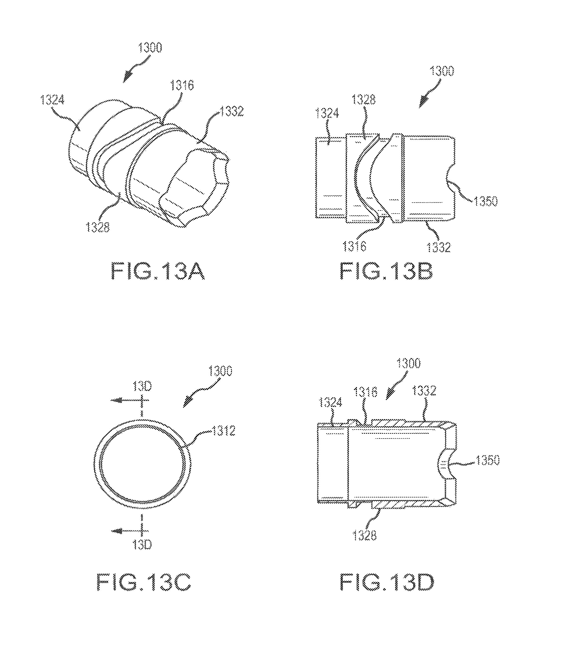
D00015

D00016

D00017
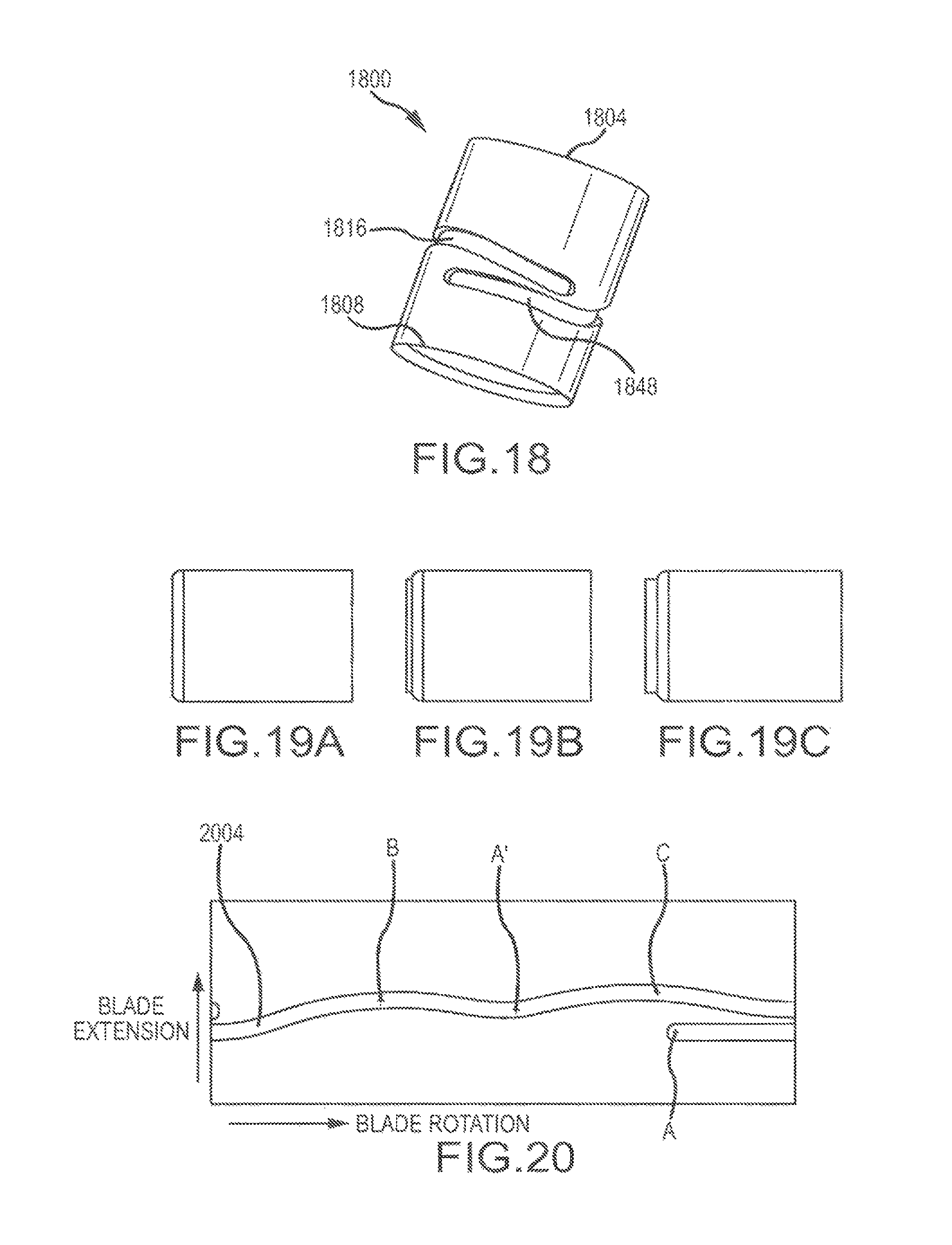
D00018

D00019
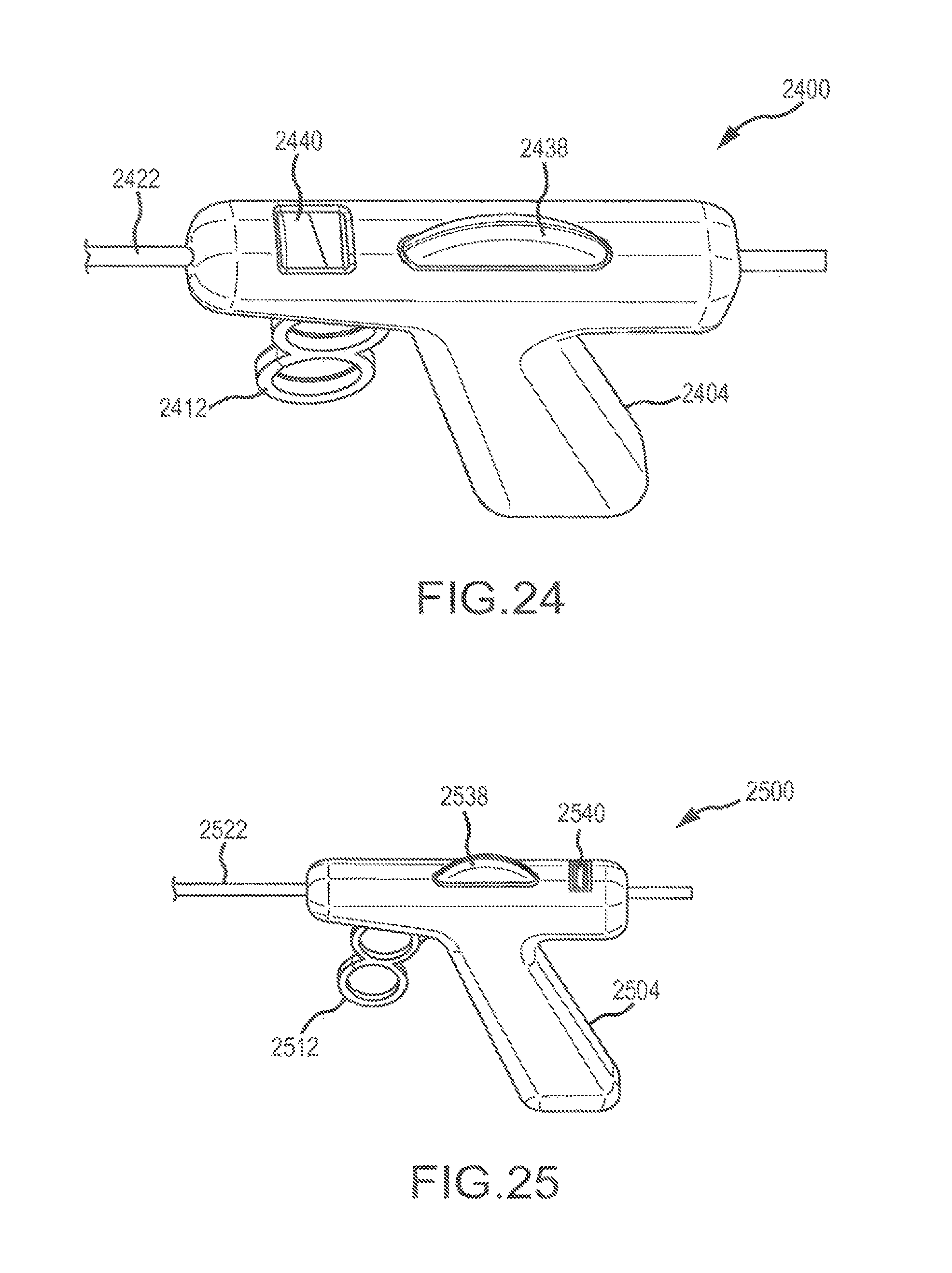
D00020

D00021

D00022

D00023

D00024

D00025

XML
uspto.report is an independent third-party trademark research tool that is not affiliated, endorsed, or sponsored by the United States Patent and Trademark Office (USPTO) or any other governmental organization. The information provided by uspto.report is based on publicly available data at the time of writing and is intended for informational purposes only.
While we strive to provide accurate and up-to-date information, we do not guarantee the accuracy, completeness, reliability, or suitability of the information displayed on this site. The use of this site is at your own risk. Any reliance you place on such information is therefore strictly at your own risk.
All official trademark data, including owner information, should be verified by visiting the official USPTO website at www.uspto.gov. This site is not intended to replace professional legal advice and should not be used as a substitute for consulting with a legal professional who is knowledgeable about trademark law.