Anti-splay device for merchandise display system
Hardy , et al. Ja
U.S. patent number 10,178,909 [Application Number 15/406,287] was granted by the patent office on 2019-01-15 for anti-splay device for merchandise display system. This patent grant is currently assigned to RTC Industries, Inc.. The grantee listed for this patent is RTC Industries, Inc.. Invention is credited to Tony Dipaolo, Stephen N. Hardy.


View All Diagrams
| United States Patent | 10,178,909 |
| Hardy , et al. | January 15, 2019 |
Anti-splay device for merchandise display system
Abstract
A merchandising display system can include one or more of a front rail configured to mount to a shelf, a first divider assembly, a second divider assembly, and a central track or floor, and a pusher assembly. In one example aspect, the example merchandising display system can be configured to prevent splaying of the divider assemblies when a row of product is loaded toward the rear of the shelf or when displaying the product in rows on the shelf. In one example, the central track in conjunction with the weight of the product can be configured to maintain even spacing between the first divider assembly and the second divider assembly, such that the first divider assembly and the second divider assembly are maintained in position on the shelf thereby maintaining the product organized in their respective rows on the shelf.
| Inventors: | Hardy; Stephen N. (Wadsworth, OH), Dipaolo; Tony (Naperville, IL) | ||||||||||
|---|---|---|---|---|---|---|---|---|---|---|---|
| Applicant: |
|
||||||||||
| Assignee: | RTC Industries, Inc. (Rolling
Meadows, IL) |
||||||||||
| Family ID: | 57966126 | ||||||||||
| Appl. No.: | 15/406,287 | ||||||||||
| Filed: | January 13, 2017 |
Prior Publication Data
| Document Identifier | Publication Date | |
|---|---|---|
| US 20170196355 A1 | Jul 13, 2017 | |
Related U.S. Patent Documents
| Application Number | Filing Date | Patent Number | Issue Date | ||
|---|---|---|---|---|---|
| 62278312 | Jan 13, 2016 | ||||
| Current U.S. Class: | 1/1 |
| Current CPC Class: | A47F 7/28 (20130101); A47F 1/126 (20130101); A47B 57/588 (20130101); A47F 7/0007 (20130101); A47F 5/005 (20130101) |
| Current International Class: | A47F 5/00 (20060101); A47F 7/00 (20060101); A47F 7/28 (20060101); A47B 57/58 (20060101); A47F 1/04 (20060101); A47F 1/12 (20060101) |
References Cited [Referenced By]
U.S. Patent Documents
| 153227 | April 1874 | Walkee |
| 154940 | September 1874 | Adams |
| 355511 | January 1887 | Danner |
| 431373 | July 1890 | Mendenhall |
| 436704 | September 1890 | Green |
| 452673 | May 1891 | Hunter |
| 551642 | December 1895 | Kleine |
| 607890 | July 1898 | Smith |
| 607891 | July 1898 | Smith |
| 632231 | September 1899 | Blades |
| 808067 | December 1905 | Briggs |
| 847863 | March 1907 | Watts |
| 927988 | July 1909 | Massey |
| 1030317 | June 1912 | Middaugh |
| 1156140 | October 1915 | Hair |
| 1271508 | July 1918 | Hall |
| 1282532 | October 1918 | Bochenek |
| 1674582 | June 1928 | Wheeler |
| 1682580 | August 1928 | Pratt |
| 1703987 | March 1929 | Butler |
| 1712080 | May 1929 | Kelly |
| 1714266 | May 1929 | Johnson |
| 1734031 | November 1929 | Carlston |
| 1786392 | December 1930 | Kemp |
| 1821350 | September 1931 | Levy |
| 1849024 | March 1932 | McKee |
| 1910516 | May 1933 | Basenberg |
| 1964597 | June 1934 | Rapellin |
| 1971749 | August 1934 | Hamilton |
| 1991102 | February 1935 | Kemaghan |
| 2013284 | September 1935 | Michaud |
| 2057627 | October 1936 | Ferris |
| 2076941 | April 1937 | Farr |
| 2079754 | May 1937 | Waxgiser |
| 2085479 | June 1937 | Shaffer et al. |
| 2110299 | March 1938 | Hinkle |
| 2111496 | March 1938 | Scriba |
| 2129122 | September 1938 | Follett |
| 2185605 | January 1940 | Murphy |
| 2218444 | October 1940 | Vineyard |
| 2284849 | June 1942 | Schreyer |
| 2308851 | January 1943 | Anderson |
| 2499088 | February 1950 | Brill |
| 2516122 | July 1950 | Hughes |
| 2520738 | August 1950 | Segal |
| 2522896 | September 1950 | Rifkin |
| 2538165 | January 1951 | Randtke |
| 2538908 | January 1951 | McKeehan |
| 2555102 | May 1951 | Anderson |
| 2563570 | August 1951 | Williams |
| 2634855 | April 1953 | Mandel |
| 2652154 | September 1953 | Stevens |
| 2670853 | March 1954 | Schneider |
| 2678045 | May 1954 | Erhard |
| 2730825 | January 1956 | Wilds |
| 2732952 | January 1956 | Skelton |
| 2738881 | March 1956 | Michel |
| 2750049 | June 1956 | Hunter |
| 2767042 | October 1956 | Kesling |
| 2775365 | December 1956 | Mestman |
| 2784871 | March 1957 | Gabrielsen |
| 2828178 | March 1958 | Dahlgren |
| 2893596 | July 1959 | Gabrielsen |
| 2918295 | December 1959 | Milner |
| 2934212 | April 1960 | Jacobson |
| 2948403 | August 1960 | Vallez |
| 2964154 | December 1960 | Erickson |
| 3083067 | March 1963 | Vos et al. |
| 3103396 | September 1963 | Portnoy |
| 3110402 | November 1963 | Mogulescu |
| 3121494 | February 1964 | Berk |
| 3122236 | February 1964 | Michiel |
| 3124254 | March 1964 | Davidson |
| 3151576 | October 1964 | Patterson |
| 3161295 | December 1964 | Chesley |
| 3166195 | January 1965 | Taber |
| 3285429 | November 1966 | Propst |
| 3300166 | January 1967 | Wojciechowski |
| 3308961 | March 1967 | Chesley |
| 3308964 | March 1967 | Pistone |
| 3331337 | July 1967 | MacKay |
| 3348732 | October 1967 | Shwarz |
| 3405716 | October 1968 | Cafiero |
| 3452899 | July 1969 | Libberton |
| 3497081 | February 1970 | Field |
| 3501016 | March 1970 | Kenneth |
| 3501019 | March 1970 | Armstron |
| 3501020 | March 1970 | Krikorian |
| 3512652 | May 1970 | Armstrong |
| D219058 | October 1970 | Kaczur |
| 3550979 | December 1970 | Protzmann |
| 3598246 | August 1971 | Galli |
| 3625371 | December 1971 | Dill |
| 3652154 | March 1972 | Gebel |
| 3667826 | June 1972 | Wood |
| 3698568 | October 1972 | Armstrong |
| 3709371 | January 1973 | Luck |
| 3751129 | August 1973 | Wright et al. |
| 3767083 | October 1973 | Webb |
| 3776388 | December 1973 | Mattheis |
| 3780876 | December 1973 | Elkins |
| 3814490 | June 1974 | Dean et al. |
| 3815519 | June 1974 | Meyer |
| 3830169 | August 1974 | Madey |
| 3836008 | September 1974 | Mraz |
| 3848745 | November 1974 | Smith |
| 3868021 | February 1975 | Heinrich |
| 3870156 | March 1975 | O'Neill |
| 3893739 | July 1975 | Bernard |
| 3923159 | December 1975 | Taylor et al. |
| 3949880 | April 1976 | Fortunato |
| 3960273 | June 1976 | Weston |
| 4007841 | February 1977 | Seipel |
| 4015886 | April 1977 | Wickenberg |
| 4042096 | August 1977 | Smith |
| 4106668 | August 1978 | Gebhardt et al. |
| 4205763 | June 1980 | Merl |
| 4266355 | May 1981 | Moss |
| 4269326 | May 1981 | Delbrouck |
| 4300693 | November 1981 | Spamer |
| 4303162 | December 1981 | Suttles |
| 4331243 | May 1982 | Doll |
| 4351439 | September 1982 | Taylor |
| 4378872 | April 1983 | Brown |
| 4397606 | August 1983 | Bruton |
| 4416380 | November 1983 | Flum |
| 4437572 | March 1984 | Hoffman |
| 4448653 | May 1984 | Wegmann |
| 4454948 | June 1984 | Spamer |
| 4454949 | June 1984 | Flum |
| 4460096 | July 1984 | Ricci |
| D275058 | August 1984 | Flum |
| 4463854 | August 1984 | MacKenzie |
| 4467927 | August 1984 | Nathan |
| 4470943 | September 1984 | Preis |
| 4476985 | October 1984 | Norberg et al. |
| 4478337 | October 1984 | Flum |
| 4482066 | November 1984 | Dykstra |
| 4488653 | December 1984 | Belokin |
| 4500147 | February 1985 | Reister |
| 4504100 | March 1985 | Chaumard |
| 4550838 | November 1985 | Nathan et al. |
| 4588093 | May 1986 | Field |
| 4589349 | May 1986 | Gebhardt et al. |
| 4590696 | May 1986 | Squitieri |
| 4593823 | June 1986 | Fershko et al. |
| 4602560 | July 1986 | Jacky |
| 4606280 | August 1986 | Poulton et al. |
| 4610491 | September 1986 | Freeman |
| 4615276 | October 1986 | Garabedian |
| 4620489 | November 1986 | Albano |
| 4629072 | December 1986 | Loew |
| 4651883 | March 1987 | Gullett et al. |
| 4685574 | August 1987 | Young et al. |
| 4705175 | November 1987 | Howard et al. |
| 4706821 | November 1987 | Kohls et al. |
| 4712694 | December 1987 | Breslow |
| 4724968 | February 1988 | Wombacher |
| 4729481 | March 1988 | Hawkinson et al. |
| 4730741 | March 1988 | Jackle, III et al. |
| 4742936 | May 1988 | Rein |
| 4744489 | May 1988 | Binder et al. |
| 4762235 | August 1988 | Howard et al. |
| 4768661 | September 1988 | Pfeifer |
| 4771898 | September 1988 | Howard et al. |
| 4775058 | October 1988 | Yatsko |
| 4776472 | October 1988 | Rosen |
| 4790037 | December 1988 | Phillips |
| 4801025 | January 1989 | Flum et al. |
| 4809855 | March 1989 | Bustos |
| 4821894 | April 1989 | Dechirot |
| 4828144 | May 1989 | Garrick |
| 4830201 | May 1989 | Breslow |
| 4836390 | June 1989 | Polvere |
| 4846367 | July 1989 | Guigan et al. |
| 4883169 | November 1989 | Flanagan, Jr. |
| 4887724 | December 1989 | Pielechowski et al. |
| 4887737 | December 1989 | Adenau |
| 4896779 | January 1990 | Jureckson |
| 4899668 | February 1990 | Valiulis |
| 4899893 | February 1990 | Robertson |
| 4901853 | February 1990 | Maryatt |
| 4901869 | February 1990 | Hawkinson et al. |
| 4901872 | February 1990 | Lang |
| 4907707 | March 1990 | Crum |
| 4923070 | May 1990 | Jackle et al. |
| 4934645 | June 1990 | Breslow |
| 4944924 | July 1990 | Mawhirt et al. |
| 4958739 | September 1990 | Spamer |
| 4981224 | January 1991 | Rushing |
| 4997094 | March 1991 | Spamer et al. |
| 5012936 | May 1991 | Crum |
| 5025936 | June 1991 | Lamoureaux |
| 5027957 | July 1991 | Skalski |
| 5054629 | October 1991 | Breen |
| 5082125 | January 1992 | Ninni |
| 5088607 | February 1992 | Risafi et al. |
| 5110192 | May 1992 | Lauterbach |
| 5111942 | May 1992 | Bernardin |
| 5123546 | June 1992 | Crum |
| 5131563 | July 1992 | Yablans |
| 5148927 | September 1992 | Gebka |
| 5159753 | November 1992 | Torrence |
| 5161702 | November 1992 | Skalski |
| 5161704 | November 1992 | Valiulis |
| 5178258 | January 1993 | Smalley et al. |
| 5183166 | February 1993 | Belokin, Jr. et al. |
| 5190186 | March 1993 | Yablans et al. |
| 5197610 | March 1993 | Bustos |
| 5197631 | March 1993 | Mishima |
| 5203463 | April 1993 | Gold |
| 5215199 | June 1993 | Bejarano |
| 5240126 | August 1993 | Foster et al. |
| 5255802 | October 1993 | Krinke et al. |
| 5265738 | November 1993 | Yablans et al. |
| 5295596 | March 1994 | Squitieri |
| 5316154 | May 1994 | Hajec, Jr. |
| 5322668 | June 1994 | Tomasso |
| 5341945 | August 1994 | Gibson |
| 5351839 | October 1994 | Beeler et al. |
| 5366099 | November 1994 | Schmid |
| 5381908 | January 1995 | Hepp |
| 5390802 | February 1995 | Pappagallo et al. |
| 5397006 | March 1995 | Terrell |
| 5397016 | March 1995 | Torrence et al. |
| 5405193 | April 1995 | Herrenbruck |
| 5408775 | April 1995 | Abramson et al. |
| 5411146 | May 1995 | Jarecki et al. |
| 5413229 | May 1995 | Zuberbuhler et al. |
| 5415297 | May 1995 | Klein et al. |
| 5419066 | May 1995 | Harnois et al. |
| 5439122 | August 1995 | Ramsay |
| 5450969 | September 1995 | Johnson et al. |
| 5458248 | October 1995 | Alain |
| 5464105 | November 1995 | Mandeltort |
| 5469975 | November 1995 | Fajnsztajn |
| 5469976 | November 1995 | Burchell |
| 5505315 | April 1996 | Carroll |
| 5542552 | August 1996 | Yablans et al. |
| 5562217 | October 1996 | Salveson et al. |
| 5577337 | November 1996 | Lin |
| 5597150 | January 1997 | Stein et al. |
| 5613621 | March 1997 | Gervasi et al. |
| D378888 | April 1997 | Bertilsson |
| 5615780 | April 1997 | Nimetz et al. |
| 5634564 | June 1997 | Spamer et al. |
| 5638963 | June 1997 | Finnelly et al. |
| 5641082 | June 1997 | Grainger |
| 5645176 | July 1997 | Jay |
| 5655670 | August 1997 | Stuart |
| 5657702 | August 1997 | Ribeyrolles |
| 5665304 | September 1997 | Heinen et al. |
| 5671851 | September 1997 | Johnson et al. |
| 5673801 | October 1997 | Markson |
| D386363 | November 1997 | Dardashti |
| 5682824 | November 1997 | Visk |
| 5685664 | November 1997 | Parham et al. |
| 5690038 | November 1997 | Merit et al. |
| 5695076 | December 1997 | Jay |
| 5695077 | December 1997 | Jay |
| 5707034 | January 1998 | Cotterill |
| 5711432 | January 1998 | Stein et al. |
| 5720230 | February 1998 | Mansfield |
| 5730320 | March 1998 | David |
| 5738019 | April 1998 | Parker |
| 5740944 | April 1998 | Crawford |
| 5743428 | April 1998 | Rankin, VI |
| 5746328 | May 1998 | Beeler et al. |
| 5749478 | May 1998 | Ellis |
| 5765390 | June 1998 | Johnson et al. |
| 5788090 | August 1998 | Kajiwara |
| 5803276 | September 1998 | Vogler |
| 5806690 | September 1998 | Johnson et al. |
| 5826731 | October 1998 | Dardashti |
| 5839588 | November 1998 | Hawkinson |
| 5848709 | December 1998 | Gelphman et al. |
| 5855283 | January 1999 | Johnson |
| D405632 | February 1999 | Parham |
| 5865324 | February 1999 | Jay et al. |
| 5868367 | February 1999 | Smith |
| 5873473 | February 1999 | Pater |
| 5873489 | February 1999 | Ide et al. |
| 5878895 | March 1999 | Springs |
| 5881910 | March 1999 | Rein |
| 5887732 | March 1999 | Zimmer et al. |
| 5904256 | May 1999 | Jay |
| 5906283 | May 1999 | Kump et al. |
| 5944201 | August 1999 | Babboni et al. |
| 5951228 | September 1999 | Pfeiffer et al. |
| 5970887 | October 1999 | Hardy |
| 5971173 | October 1999 | Valiulis et al. |
| 5971204 | October 1999 | Apps |
| 5975318 | November 1999 | Jay |
| 5992652 | November 1999 | Springs |
| 5992653 | November 1999 | Anderson et al. |
| 6003690 | December 1999 | Allen et al. |
| 6006678 | December 1999 | Merit et al. |
| 6007248 | December 1999 | Fulterer |
| 6015051 | January 2000 | Battaglia |
| 6021908 | February 2000 | Mathews |
| 6026984 | February 2000 | Perrin |
| 6035569 | March 2000 | Nagel et al. |
| 6041720 | March 2000 | Hardy |
| 6044982 | April 2000 | Stuart |
| 6047647 | April 2000 | Laraia, Jr. |
| 6068142 | May 2000 | Primiano |
| 6076670 | June 2000 | Yeranossian |
| 6082556 | July 2000 | Primiano et al. |
| 6082557 | July 2000 | Leahy |
| 6082558 | July 2000 | Battaglia |
| 6089385 | July 2000 | Nozawa |
| 6102185 | August 2000 | Neuwirth et al. |
| 6112938 | September 2000 | Apps |
| 6129218 | October 2000 | Henry et al. |
| 6132158 | October 2000 | Pfeiffer et al. |
| 6142316 | November 2000 | Harbour et al. |
| 6142317 | November 2000 | Merl |
| 6155438 | December 2000 | Close |
| 6158598 | December 2000 | Josefsson |
| 6164462 | December 2000 | Mumford |
| 6164491 | December 2000 | Bustos et al. |
| 6173845 | January 2001 | Higgins et al. |
| 6186725 | February 2001 | Konstant |
| 6189734 | February 2001 | Apps et al. |
| 6209731 | April 2001 | Spamer et al. |
| 6209733 | April 2001 | Higgins et al. |
| 6226910 | May 2001 | Ireland |
| 6227385 | May 2001 | Nickerson |
| 6227386 | May 2001 | Close |
| 6234325 | May 2001 | Higgins et al. |
| 6234326 | May 2001 | Higgins et al. |
| 6234328 | May 2001 | Mason |
| 6237784 | May 2001 | Primiano |
| D445615 | July 2001 | Burke |
| 6253954 | July 2001 | Yasaka |
| 6299004 | October 2001 | Thalenfeld et al. |
| 6305559 | October 2001 | Hardy |
| 6308839 | October 2001 | Steinberg et al. |
| 6309034 | October 2001 | Credle, Jr. et al. |
| 6311852 | November 2001 | Ireland |
| 6325221 | December 2001 | Parham |
| 6325222 | December 2001 | Avery et al. |
| 6330758 | December 2001 | Feibelman |
| 6357606 | March 2002 | Henry |
| 6357985 | March 2002 | Anzani et al. |
| 6375015 | April 2002 | Wingate |
| 6378727 | April 2002 | Dupuis et al. |
| 6382431 | May 2002 | Burke |
| 6390310 | May 2002 | Insalaco |
| 6398044 | June 2002 | Robertson |
| 6401942 | June 2002 | Eckert |
| 6405880 | June 2002 | Webb |
| 6409026 | June 2002 | Watanabe |
| 6409027 | June 2002 | Chang et al. |
| 6409028 | June 2002 | Nickerson |
| 6419100 | July 2002 | Menz et al. |
| 6428123 | August 2002 | Lucht et al. |
| 6431808 | August 2002 | Lowrey et al. |
| 6435359 | August 2002 | Priminano |
| 6439402 | August 2002 | Robertson |
| 6454107 | September 2002 | Belanger et al. |
| 6464089 | October 2002 | Rankin, VI |
| 6471053 | October 2002 | Feibelman |
| 6471081 | October 2002 | Weiler |
| 6484891 | November 2002 | Burke |
| 6490983 | December 2002 | Nicholson et al. |
| 6497326 | December 2002 | Osawa |
| 6505747 | January 2003 | Robertson |
| 6523664 | February 2003 | Shaw et al. |
| 6523702 | February 2003 | Primiano et al. |
| 6523703 | February 2003 | Robertson |
| 6527127 | March 2003 | Dumontet |
| 6533131 | March 2003 | Bada |
| 6550636 | April 2003 | Simpson |
| 6553702 | April 2003 | Bacnik |
| 6554143 | April 2003 | Robertson |
| 6571498 | June 2003 | Cyrluk |
| 6598754 | July 2003 | Weiler |
| 6604638 | August 2003 | Primiano et al. |
| 6615995 | September 2003 | Primiano et al. |
| 6622874 | September 2003 | Hawkinson |
| 6637604 | October 2003 | Jay |
| 6648151 | November 2003 | Battaglia et al. |
| 6651828 | November 2003 | Dimattio et al. |
| 6655536 | December 2003 | Jo et al. |
| 6659293 | December 2003 | Smith |
| 6666533 | December 2003 | Stavros |
| D485699 | January 2004 | Mueller et al. |
| 6679033 | January 2004 | Hart et al. |
| 6679389 | January 2004 | Robertson et al. |
| 6688567 | February 2004 | Fast et al. |
| 6691891 | February 2004 | Maldonado |
| 6695152 | February 2004 | Fabrizio et al. |
| 6715621 | April 2004 | Boron |
| 6722509 | April 2004 | Robertson et al. |
| 6739461 | May 2004 | Robinson |
| 6745905 | June 2004 | Bernstein |
| 6749070 | June 2004 | Corbett, Jr. et al. |
| 6749084 | June 2004 | Thompson |
| 6756975 | June 2004 | Kishida et al. |
| 6758349 | July 2004 | Kwap et al. |
| 6769552 | August 2004 | Thalenfeld |
| 6772888 | August 2004 | Burke |
| 6779670 | August 2004 | Primiano et al. |
| 6786341 | September 2004 | Stinnett et al. |
| 6793185 | September 2004 | Joliey |
| 6796445 | September 2004 | Cyrluk |
| 6799523 | October 2004 | Cunha |
| 6820754 | November 2004 | Ondrasik |
| 6823997 | November 2004 | Linden et al. |
| 6824009 | November 2004 | Hardy |
| 6830146 | December 2004 | Scully et al. |
| 6830157 | December 2004 | Robertson et al. |
| 6843382 | January 2005 | Kanouchi et al. |
| 6843632 | January 2005 | Hollander |
| 6860046 | March 2005 | Squitieri |
| 6866156 | March 2005 | Nagel et al. |
| 6867824 | March 2005 | Eiraku et al. |
| 6874646 | April 2005 | Jay |
| 6889854 | May 2005 | Burke |
| 6889855 | May 2005 | Nagel |
| 6902285 | June 2005 | Eiraku et al. |
| 6918495 | July 2005 | Hoy |
| 6918736 | July 2005 | Hart et al. |
| 6919933 | July 2005 | Zhang et al. |
| 6923330 | August 2005 | Nagel |
| 6929133 | August 2005 | Knapp, III et al. |
| 6948900 | September 2005 | Neuman |
| 6955269 | October 2005 | Menz |
| 6957941 | October 2005 | Hart et al. |
| 6962260 | November 2005 | Jay et al. |
| 6963386 | November 2005 | Poliakine et al. |
| 6964235 | November 2005 | Hardy |
| 6964344 | November 2005 | Kim |
| 6976598 | December 2005 | Engel |
| 6981597 | January 2006 | Cash |
| 7004334 | February 2006 | Walsh et al. |
| 7007790 | March 2006 | Brannon |
| 7028450 | April 2006 | Hart et al. |
| 7028852 | April 2006 | Johnson et al. |
| 7063217 | June 2006 | Burke |
| 7080969 | July 2006 | Hart et al. |
| 7083054 | August 2006 | Squitieri |
| 7086541 | August 2006 | Robertson |
| 7093546 | August 2006 | Hardy |
| 7104026 | September 2006 | Welborn et al. |
| 7104410 | September 2006 | Primiano |
| 7108143 | September 2006 | Lin |
| 7111914 | September 2006 | Avendano |
| 7114606 | October 2006 | Shaw et al. |
| 7124898 | October 2006 | Richter et al. |
| 7140499 | November 2006 | Burke |
| 7140705 | November 2006 | Dressendorfer et al. |
| 7150365 | December 2006 | Hardy et al. |
| 7152536 | December 2006 | Hardy |
| 7168546 | January 2007 | Plesh, Sr. |
| 7168579 | January 2007 | Richter et al. |
| 7182209 | February 2007 | Squitieri |
| 7195123 | March 2007 | Roslof et al. |
| 7198340 | April 2007 | Ertz |
| 7200903 | April 2007 | Shaw et al. |
| 7201281 | April 2007 | Welker |
| 7216770 | May 2007 | Mueller et al. |
| 7229143 | June 2007 | Gilman |
| 7293663 | November 2007 | Lavery, Jr. |
| 7299934 | November 2007 | Hardy et al. |
| 7318532 | January 2008 | Lee et al. |
| 7347335 | March 2008 | Rankin, VI et al. |
| 7357469 | April 2008 | Ertz |
| 7395938 | July 2008 | Merit et al. |
| 7398876 | July 2008 | Vestergaard |
| 7404494 | July 2008 | Hardy |
| 7419062 | September 2008 | Mason |
| 7424957 | September 2008 | Luberto |
| 7451881 | November 2008 | Hardy et al. |
| 7458473 | December 2008 | Mason |
| 7478731 | January 2009 | Mason |
| 7497342 | March 2009 | Hardy |
| 7500571 | March 2009 | Hawkinson |
| 7530452 | May 2009 | Vestergaard |
| 7621409 | November 2009 | Hardy et al. |
| 7626913 | December 2009 | Usami |
| 7631771 | December 2009 | Nagel et al. |
| 7641057 | January 2010 | Mueller et al. |
| 7681743 | March 2010 | Hanretty et al. |
| 7681744 | March 2010 | Johnson |
| 7686185 | March 2010 | Zychinski |
| D613101 | April 2010 | Hardy |
| 7703614 | April 2010 | Schneider et al. |
| 7717276 | May 2010 | Alves |
| 7768399 | August 2010 | Hachmann et al. |
| 7784623 | August 2010 | Mueller et al. |
| 7784644 | August 2010 | Albert et al. |
| 7792711 | September 2010 | Swafford, Jr. et al. |
| 7815060 | October 2010 | Iellimo |
| 7823724 | November 2010 | Mowe et al. |
| 7823734 | November 2010 | Hardy |
| 7828158 | November 2010 | Colelli et al. |
| 7882969 | February 2011 | Gerstner et al. |
| 7896172 | March 2011 | Hester |
| 7918353 | April 2011 | Luberto |
| 7931156 | April 2011 | Hardy |
| 7934609 | May 2011 | Alves et al. |
| 7954635 | June 2011 | Biondi et al. |
| 7980398 | July 2011 | Kahl et al. |
| 7993088 | August 2011 | Sonon et al. |
| 8016139 | September 2011 | Hanners et al. |
| 8025162 | September 2011 | Hardy |
| 8038017 | October 2011 | Close |
| 8096427 | January 2012 | Hardy |
| 8113360 | February 2012 | Olson |
| 8113601 | February 2012 | Hardy |
| D655107 | March 2012 | Clark et al. |
| 8127944 | March 2012 | Hardy |
| 8162154 | April 2012 | Trulaske, Sr. |
| 8167149 | May 2012 | Wamsley et al. |
| 8177076 | May 2012 | Rataiczak, III et al. |
| 8215520 | July 2012 | Miller et al. |
| 8225946 | July 2012 | Yang et al. |
| 8240486 | August 2012 | Niederhuefner et al. |
| 8267258 | September 2012 | Allwright et al. |
| 8276772 | October 2012 | Kim |
| 8302783 | November 2012 | Harris et al. |
| 8312999 | November 2012 | Hardy |
| 8322544 | December 2012 | Hardy |
| 8333285 | December 2012 | Kiehnau et al. |
| 8342340 | January 2013 | Rataiczak, III et al. |
| 8360253 | January 2013 | Hardy |
| 8376154 | February 2013 | Sun |
| 8397922 | March 2013 | Kahl et al. |
| 8485391 | July 2013 | Vlastakis et al. |
| 8556092 | October 2013 | Valiulis et al. |
| 8573379 | November 2013 | Brugmann |
| 8579123 | November 2013 | Mueller et al. |
| 8622227 | January 2014 | Bird et al. |
| 8657126 | February 2014 | Loftin et al. |
| 8662325 | March 2014 | Davis et al. |
| 8739984 | June 2014 | Hardy |
| 8763819 | July 2014 | Theisen et al. |
| 8844431 | September 2014 | Davis et al. |
| 8967394 | March 2015 | Hardy et al. |
| 8973765 | March 2015 | Wamsley et al. |
| 8978904 | March 2015 | Hardy |
| 9016483 | April 2015 | Howley |
| 9060624 | June 2015 | Hardy |
| 9138075 | September 2015 | Hardy et al. |
| 9149132 | October 2015 | Hardy |
| 9173504 | November 2015 | Hardy |
| 9259102 | February 2016 | Hardy et al. |
| 9265362 | February 2016 | Hardy |
| 9445675 | September 2016 | DeSena |
| 9486088 | November 2016 | Hardy et al. |
| 9668590 | June 2017 | Bruegmann |
| 2001/0002658 | June 2001 | Parham |
| 2001/0010302 | August 2001 | Nickerson |
| 2001/0017284 | August 2001 | Watanabe |
| 2001/0019032 | September 2001 | Battaglia et al. |
| 2001/0020604 | September 2001 | Battaglia et al. |
| 2001/0020606 | September 2001 | Battaglia et al. |
| 2001/0042706 | November 2001 | Ryan et al. |
| 2001/0045403 | November 2001 | Robertson |
| 2001/0054297 | December 2001 | Credle et al. |
| 2002/0036178 | March 2002 | Tombu |
| 2002/0066706 | June 2002 | Robertson |
| 2002/0088762 | July 2002 | Burke |
| 2002/0108916 | August 2002 | Nickerson |
| 2002/0148794 | October 2002 | Marihugh |
| 2002/0170866 | November 2002 | Johnson et al. |
| 2002/0179553 | December 2002 | Squitieri |
| 2002/0182050 | December 2002 | Hart et al. |
| 2002/0189201 | December 2002 | Hart et al. |
| 2002/0189209 | December 2002 | Hart et al. |
| 2003/0000956 | January 2003 | Maldonado |
| 2003/0007859 | January 2003 | Hart et al. |
| 2003/0010732 | January 2003 | Burke |
| 2003/0024889 | February 2003 | Dumontet |
| 2003/0057167 | March 2003 | Johnson et al. |
| 2003/0061973 | April 2003 | Bustos |
| 2003/0066811 | April 2003 | Dimattio et al. |
| 2003/0080075 | May 2003 | Primiano et al. |
| 2003/0084827 | May 2003 | Nicholson et al. |
| 2003/0085187 | May 2003 | Johnson et al. |
| 2003/0106867 | June 2003 | Caterinacci |
| 2003/0132178 | July 2003 | Jay et al. |
| 2003/0132182 | July 2003 | Jay |
| 2003/0136750 | July 2003 | Fujii et al. |
| 2003/0141265 | July 2003 | Jo et al. |
| 2003/0150829 | August 2003 | Linden et al. |
| 2003/0168420 | September 2003 | Primiano |
| 2003/0201203 | October 2003 | Fast et al. |
| 2003/0217980 | November 2003 | Johnson et al. |
| 2003/0226815 | December 2003 | Gaunt et al. |
| 2004/0000528 | January 2004 | Nagel |
| 2004/0004046 | January 2004 | Primiano et al. |
| 2004/0011754 | January 2004 | Zadak |
| 2004/0020879 | February 2004 | Close |
| 2004/0065631 | April 2004 | Nagel |
| 2004/0079715 | April 2004 | Richter et al. |
| 2004/0084390 | May 2004 | Bernstein |
| 2004/0094493 | May 2004 | Higgins |
| 2004/0104239 | June 2004 | Black et al. |
| 2004/0105556 | June 2004 | Grove |
| 2004/0118793 | June 2004 | Burke |
| 2004/0118795 | June 2004 | Burke |
| 2004/0140276 | July 2004 | Waldron |
| 2004/0140278 | July 2004 | Mueller et al. |
| 2004/0140279 | July 2004 | Mueller et al. |
| 2004/0178156 | September 2004 | Knowing et al. |
| 2004/0182805 | September 2004 | Harper |
| 2004/0200793 | October 2004 | Hardy |
| 2004/0206054 | October 2004 | Welborn et al. |
| 2004/0232092 | November 2004 | Cash |
| 2004/0245197 | December 2004 | McElvaney |
| 2004/0247422 | December 2004 | Neumann et al. |
| 2004/0255500 | December 2004 | Fast et al. |
| 2005/0035075 | February 2005 | Walker |
| 2005/0040123 | February 2005 | Ali |
| 2005/0072657 | April 2005 | Lawless et al. |
| 2005/0072747 | April 2005 | Roslof et al. |
| 2005/0076817 | April 2005 | Boks et al. |
| 2005/0077259 | April 2005 | Menz |
| 2005/0092702 | May 2005 | Nagel |
| 2005/0098515 | May 2005 | Close |
| 2005/0127014 | June 2005 | Richter et al. |
| 2005/0133471 | June 2005 | Squitieri |
| 2005/0139560 | June 2005 | Whiteside et al. |
| 2005/0150847 | July 2005 | Hawkinson |
| 2005/0188574 | September 2005 | Lowry |
| 2005/0189310 | September 2005 | Richter et al. |
| 2005/0199563 | September 2005 | Richter et al. |
| 2005/0199564 | September 2005 | Johnson et al. |
| 2005/0199565 | September 2005 | Richter et al. |
| 2005/0218094 | October 2005 | Howerton et al. |
| 2005/0224437 | October 2005 | Lee |
| 2005/0249577 | November 2005 | Hart et al. |
| 2005/0258113 | November 2005 | Close et al. |
| 2005/0263465 | December 2005 | Chung |
| 2005/0286700 | December 2005 | Hardy |
| 2006/0001337 | January 2006 | Walburn |
| 2006/0032827 | February 2006 | Phoy |
| 2006/0049122 | March 2006 | Mueller et al. |
| 2006/0049125 | March 2006 | Stowell |
| 2006/0104758 | May 2006 | Hart et al. |
| 2006/0163180 | July 2006 | Rankin et al. |
| 2006/0163272 | July 2006 | Gamble |
| 2006/0186064 | August 2006 | Merit et al. |
| 2006/0186065 | August 2006 | Ciesick |
| 2006/0186066 | August 2006 | Johnson et al. |
| 2006/0196840 | September 2006 | Jay et al. |
| 2006/0213852 | September 2006 | Kwon |
| 2006/0226095 | October 2006 | Hardy |
| 2006/0237381 | October 2006 | Lockwood et al. |
| 2006/0260518 | November 2006 | Josefsson et al. |
| 2006/0263192 | November 2006 | Hart et al. |
| 2006/0273053 | December 2006 | Roslof et al. |
| 2006/0283150 | December 2006 | Hart et al. |
| 2006/0283151 | December 2006 | Welborn et al. |
| 2007/0006885 | January 2007 | Shultz et al. |
| 2007/0029270 | February 2007 | Hawkinson |
| 2007/0068885 | March 2007 | Busto et al. |
| 2007/0075028 | April 2007 | Nagel |
| 2007/0108142 | May 2007 | Medcalf et al. |
| 2007/0108146 | May 2007 | Nawrocki |
| 2007/0119798 | May 2007 | Hanretty |
| 2007/0119799 | May 2007 | Hanretty |
| 2007/0138114 | June 2007 | Dumontet |
| 2007/0170127 | July 2007 | Johnson |
| 2007/0175839 | August 2007 | Schneider et al. |
| 2007/0175844 | August 2007 | Schneider |
| 2007/0187344 | August 2007 | Mueller et al. |
| 2007/0194037 | August 2007 | Close |
| 2007/0251905 | November 2007 | Trotta |
| 2007/0256992 | November 2007 | Olson |
| 2007/0267364 | November 2007 | Barkdoll |
| 2007/0272634 | November 2007 | Richter et al. |
| 2007/0278164 | December 2007 | Lang et al. |
| 2008/0000859 | January 2008 | Yang et al. |
| 2008/0011696 | January 2008 | Richter et al. |
| 2008/0017598 | January 2008 | Rataiczak et al. |
| 2008/0129161 | June 2008 | Menz et al. |
| 2008/0142458 | June 2008 | Medcalf |
| 2008/0156751 | July 2008 | Richter et al. |
| 2008/0156752 | July 2008 | Bryson et al. |
| 2008/0164229 | July 2008 | Richter et al. |
| 2008/0250986 | October 2008 | Boon |
| 2008/0296241 | December 2008 | Alves et al. |
| 2008/0314852 | December 2008 | Richter et al. |
| 2009/0020548 | January 2009 | VanDruff |
| 2009/0084812 | April 2009 | Kirschner |
| 2009/0101606 | April 2009 | Olson |
| 2009/0248198 | October 2009 | Siegel et al. |
| 2009/0272705 | November 2009 | Francis |
| 2009/0277853 | November 2009 | Bauer |
| 2010/0012602 | January 2010 | Valiulis et al. |
| 2010/0072152 | March 2010 | Kim |
| 2010/0078402 | April 2010 | Davis et al. |
| 2010/0089847 | April 2010 | Rataiczak, III et al. |
| 2010/0096345 | April 2010 | Crawbuck et al. |
| 2010/0107670 | May 2010 | Kottke et al. |
| 2010/0108624 | May 2010 | Sparkowski |
| 2010/0133214 | June 2010 | Evans |
| 2010/0176075 | July 2010 | Nagel et al. |
| 2010/0200526 | August 2010 | Barkdoll |
| 2010/0206829 | August 2010 | Clements et al. |
| 2010/0252519 | October 2010 | Hanners et al. |
| 2010/0258513 | October 2010 | Meyer et al. |
| 2010/0276383 | November 2010 | Hardy |
| 2011/0121022 | May 2011 | Sholl et al. |
| 2011/0147323 | June 2011 | Sainato |
| 2011/0168652 | July 2011 | Barkdoll |
| 2011/0174750 | July 2011 | Poulokefalos |
| 2011/0204012 | August 2011 | Eguchi et al. |
| 2011/0215060 | September 2011 | Niederhuefner |
| 2011/0218889 | September 2011 | Westberg et al. |
| 2011/0220597 | September 2011 | Sherretts et al. |
| 2011/0284571 | November 2011 | Lockwood et al. |
| 2011/0304316 | December 2011 | Hachmann et al. |
| 2012/0074088 | March 2012 | Dotson et al. |
| 2012/0090208 | April 2012 | Grant |
| 2012/0091162 | April 2012 | Overhultz et al. |
| 2012/0118840 | May 2012 | Howley |
| 2012/0217212 | August 2012 | Czalkiewicz et al. |
| 2012/0255922 | October 2012 | Bryson |
| 2012/0285916 | November 2012 | O'Quinn et al. |
| 2013/0015155 | January 2013 | Brugmann |
| 2013/0026117 | January 2013 | Hardy |
| 2013/0037562 | February 2013 | Close |
| 2013/0200019 | August 2013 | Hardy |
| 2013/0200026 | August 2013 | Bryson |
| 2013/0206713 | August 2013 | Hardy |
| 2013/0213916 | August 2013 | Leahy et al. |
| 2013/0270204 | October 2013 | Bird |
| 2014/0008382 | January 2014 | Christianson |
| 2014/0091696 | April 2014 | Welker et al. |
| 2014/0124463 | May 2014 | Goehring |
| 2014/0138330 | May 2014 | Hardy |
| 2014/0151313 | June 2014 | Breslow |
| 2014/0305891 | October 2014 | Vogler et al. |
| 2014/0319088 | October 2014 | Neumann et al. |
| 2014/0326691 | November 2014 | Hardy |
| 2014/0360953 | December 2014 | Pichel |
| 2015/0034576 | February 2015 | Wong |
| 2015/0090675 | April 2015 | Vosshernrich |
| 2015/0320237 | November 2015 | Hardy et al. |
| 2017/0020302 | January 2017 | Goehring |
| 2012301697 | Apr 2014 | AU | |||
| 2012301707 | Apr 2014 | AU | |||
| 906083 | Apr 1987 | BE | |||
| 1013877 | Nov 2002 | BE | |||
| 394537 | Jun 1965 | CH | |||
| 412251 | Apr 1966 | CH | |||
| 2642158 | Sep 2004 | CN | |||
| 101472509 | Jul 2009 | CN | |||
| 969003 | Apr 1958 | DE | |||
| 1819158 | Oct 1960 | DE | |||
| 2002720 | Jul 1971 | DE | |||
| 7311113 | Aug 1973 | DE | |||
| 2232398 | Jan 1974 | DE | |||
| 2825724 | Dec 1979 | DE | |||
| 8308485 | Sep 1983 | DE | |||
| 3211880 | Oct 1983 | DE | |||
| 8426651 | Feb 1985 | DE | |||
| 8520125 | Jan 1986 | DE | |||
| 8717386 | Mar 1988 | DE | |||
| 8717386.7 | Apr 1988 | DE | |||
| 3707410 | Sep 1988 | DE | |||
| 9300431.1 | Mar 1993 | DE | |||
| 29618870 | Dec 1996 | DE | |||
| 29902688 | Jul 1999 | DE | |||
| 19808162 | Sep 1999 | DE | |||
| 202007011927 | Nov 2007 | DE | |||
| 202013102529 | Jun 2013 | DE | |||
| 0004921 | Oct 1979 | EP | |||
| 0018003 | Oct 1980 | EP | |||
| 69003 | Jan 1983 | EP | |||
| 0176209 | Apr 1986 | EP | |||
| 0224107 | Jun 1987 | EP | |||
| 270016 | Jun 1988 | EP | |||
| 298500 | Jan 1989 | EP | |||
| 336696 | Oct 1989 | EP | |||
| 0337340 | Oct 1989 | EP | |||
| 0408400 | Jan 1991 | EP | |||
| 0454586 | Oct 1991 | EP | |||
| 478570 | Apr 1992 | EP | |||
| 555935 | Aug 1993 | EP | |||
| 0568396 | Nov 1993 | EP | |||
| 0587059 | Mar 1994 | EP | |||
| WO-2016124760 | Aug 2016 | WO | |||
Other References
|
Mar. 29, 2017--(PCT) International Search Report and Written Opinion--App PCT/US2017/013494. cited by applicant . Sep. 25, 2015--(CA) Examiner's Report--App 2847521. cited by applicant . Feb. 9, 2016--(AU) Office Action--App. 2014228865. cited by applicant . Apr. 19, 2016--(EP) Office Action--App. 15172675. cited by applicant . RTC Industries, Inc. v. FFR Merchandising, Inc., Complaint, Case: 1 :17-cv-03595 Document #:1 Filed: May 12, 2017 p. 1 of 10 Page ID #:1. cited by applicant . Mar. 22, 2016--(WO) International Search Report and Written Opinion--App PCT/US2015/067494. cited by applicant. |
Primary Examiner: Wright; Kimberley S
Attorney, Agent or Firm: Banner & Witcoff, Ltd.
Parent Case Text
RELATED APPLICATIONS
This application claims priority to U.S. Provisional Application No. 62/278,312, filed on Jan. 13, 2016, and relates to U.S. application Ser. No. 14/611,767, filed on Feb. 2, 2015, which is a continuation of U.S. application Ser. No. 13/833,500, filed on Mar. 15, 2013, and granted as U.S. Pat. No. 8,967,394, which is a continuation-in-part of U.S. application Ser. No. 13/542,419 filed on Jul. 5, 2012, and granted as U.S. Pat. No. 8,739,984, which is a is a continuation-in-part of U.S. application Ser. No. 12/639,656 filed Dec. 16, 2009, and granted as U.S. Pat. No. 8,322,544, which is a continuation-in-part application of U.S. application Ser. No. 12/357,860 filed Jan. 22, 2009, and granted as U.S. Pat. No. 8,453,850, which is a continuation-in-part application of U.S. application Ser. No. 11/760,196 filed Jun. 8, 2007, and granted as U.S. Pat. No. 8,312,999, which is a continuation-in-part application of U.S. application Ser. No. 11/411,761 filed Apr. 25, 2006, and granted as U.S. Pat. No. 7,823,734, which claims benefit to U.S. Provisional Application Nos. 60/716,362 filed Sep. 12, 2005 and 60/734,692 filed Nov. 8, 2005, all of which are incorporated herein fully by reference. U.S. application Ser. No. 13/542,419 also claims benefit to U.S. Provisional Application Nos. 61/530,736 filed Sep. 2, 2011, 61/542,473 filed Oct. 3, 2011, and 61/553,545 filed Oct. 31, 2011. All of the above applications are incorporated herein fully by reference.
Claims
What is claimed is:
1. A merchandise display system comprising: a front rail configured to mount to a shelf; a first divider assembly configured to connect to the front rail, the first divider assembly defining a first divider assembly front and a first divider assembly rear the first divider assembly comprising a first divider wall separating the first divider assembly to define a first track and a second track for supporting product; a second divider assembly defining a second divider assembly front and a second divider assembly rear, the second divider assembly configured to connect to the front rail, the second divider assembly comprising a second divider wall separating the second divider assembly to define a third track and a fourth track for supporting product; and a floor configured to connect to the front rail and configured to extend between the first divider wall and the second divider wall; wherein the floor engages the first divider assembly at the first divider assembly rear and the floor engages the second divider assembly at the second divider assembly rear to aid in preventing the first divider assembly and the second divider assembly from splaying in relation to one another; wherein the floor further comprises a spring for raising the floor above a rear portion of the first divider assembly and a rear portion of the second divider assembly when the merchandise display system is in an unloaded position.
2. The merchandise display system of claim 1 wherein the first divider assembly and the second divider assembly spacing is adjustable.
3. The merchandise display system of claim 2 wherein the first track and the second track comprises a first plurality of notches, and wherein the third track and the fourth track comprises a second plurality of notches, the floor comprising a first projection and a second projection, the first projection configured to extend into one of the first plurality of notches and the second projection configured to extend into one of the second plurality of notches.
4. The merchandise display system of claim 1 wherein the floor further comprises a pusher assembly having a pusher paddle and a coiled spring positioned behind the pusher paddle and configured to bias the pusher paddle toward the front rail.
5. The merchandise display system of claim 1 wherein the floor, the second track, and the third track together form a surface for receiving at least one product.
6. The merchandise display system of claim 1 further comprising a third divider assembly, the third divider assembly configured to connect to the front rail, the third divider assembly comprising a third divider wall separating the third divider assembly to define a fifth track and a sixth track for supporting product and a second floor and wherein the second floor is configured to connect to the front rail and is configured to extend between the second divider wall and the third divider wall; wherein the second floor engages the second divider assembly and the second floor engages the third divider assembly to prevent the second divider assembly and the third divider assembly from splaying in relation to one another.
7. The merchandise display system of claim 1 wherein weight of the product causes the floor to engage the first divider assembly and the second divider assembly to aid in preventing the first divider assembly and the second divider assembly from splaying in relation to one another.
8. A method comprising: providing a front rail configured to connect to a shelf; providing a first divider assembly and configuring the first divider assembly to connect to the front rail, the first divider assembly comprising a first divider wall and at least one first floor for supporting product; providing a second divider assembly, configuring the second divider assembly to connect to the front rail, the second divider assembly comprising a second divider wall and at least one second floor for supporting product; providing a track and configuring the track to connect to the front rail and configuring the track to extend between the first divider wall and the second divider wall, and configuring the track to engage the first divider assembly and configuring the track to engage the second divider assembly to help prevent the first divider assembly and the second divider assembly from splaying in relation to one another; and providing the track with a spring for raising the track above a rear portion of the first divider assembly and a rear portion of the second divider assembly the track is in an unloaded position.
9. The method of claim 8 further comprising configuring the first divider assembly and the second divider assembly spacing to be adjustable.
10. The method of claim 9 further comprising providing the at least one floor of the first divider assembly with a first plurality of notches, providing the at least one floor of the second divider assembly with a second plurality of notches, providing the track with a first projection and a second projection, where the first projection is configured to extend into one of the first plurality of notches and the second projection is configured to extend into one of the second plurality of notches.
11. The method of claim 8 further comprising providing the track with a pusher assembly having a pusher paddle and positioning a coiled spring behind the pusher paddle and configuring the coiled spring to bias the pusher paddle toward the front rail.
12. The method of claim 8 wherein the track, the at least one first floor, the at least one second floor together form a surface for receiving at least one product.
13. The method of claim 8 further comprising providing a third divider assembly, configuring the third divider assembly to connect to the front rail, providing the third divider assembly with a third divider wall and at least one third floor for supporting product and a second track and configuring the second track to connect to the front rail and to extend between the second divider wall and the third divider wall; wherein the second track engages the second divider assembly and the second floor engages the third divider assembly to help prevent the second divider assembly and the third divider assembly from splaying in relation to one another.
14. The method of claim 8 further comprising configuring the track to engage the first divider assembly at a rear portion of the first divider assembly and configuring the track to engage the second divider assembly at a rear portion of the second divider assembly such that weight of product loaded on the at least one first floor, the at least one second floor, and the track aids in preventing the first divider assembly and the second divider assembly from splaying in relation to one another.
15. A merchandise display system comprising: a front rail configured to mount to a shelf; a first divider assembly configured to connect to the front rail, the first divider assembly comprising a first divider assembly front and a first divider assembly rear the first divider assembly comprising a first divider wall separating the first divider assembly to define a first track and a second track for supporting product, the first track and the second track comprising a first plurality of notches; a second divider assembly defining a second divider assembly front and a second divider assembly rear, the second divider assembly configured to connect to the front rail, the second divider assembly comprising a second divider wall separating the second divider assembly to define a third track and a forth track for supporting product, the third track and the forth track comprising a second plurality of notches; and a floor configured to connect to the front rail and configured to extend between the first divider wall and the second divider wall, the floor having a first projection and a second projection; wherein the floor engages the first divider assembly at the first divider assembly rear and the floor engages the second divider assembly at the second divider assembly rear such that the first projection extends into one of the first plurality of notches and the second projection extends into one of the second plurality of notches to aid in preventing the first divider assembly and the second divider assembly from splaying in relation to one another; wherein weight of a product causes the floor to engage the first divider assembly and the second divider assembly to aid in preventing the first divider assembly and the second divider assembly from splaying in relation to one another; wherein a spring causes the floor to disengage the first divider assembly and the second divider assembly when the weight of the product is removed.
16. The merchandise display system of claim 15 wherein the first divider assembly and the second divider assembly spacing is adjustable.
17. The merchandise display system of claim 15 wherein the floor further comprises a pusher assembly having a pusher paddle and a coiled spring positioned behind the pusher paddle and configured to bias the pusher paddle toward the front rail.
18. The merchandise display system of claim 15 wherein the floor, the second track, and the third track together form a surface for receiving at least one product.
19. The merchandise display system of claim 15 further comprising a third divider assembly, the third divider assembly configured to connect to the front rail, the third divider assembly comprising a third divider wall separating the third divider assembly to define a fifth track and a sixth track for supporting product and a second floor and wherein the second floor is configured to connect to the front rail and is configured to extend between the second divider wall and the third divider wall, wherein the second floor engages the second divider assembly and the second floor engages the third divider assembly to help prevent the second divider assembly and the third divider assembly from splaying in relation to one another.
Description
FIELD
The exemplary embodiments relate generally to a shelf assembly for use in merchandising product and more particularly to a shelf assembly having improved mechanisms for displaying and pushing product on the shelves.
BACKGROUND
Retail and wholesale stores, such as convenience stores, drug stores, grocery stores, discount stores, and the like, require a large amount of shelving both to store product and to display the product to consumers. In displaying product, it is may be desirable for the product on the shelves to be situated toward the front of the shelf so that the product is visible and accessible to consumers. In the case of coolers or refrigerators that are used to store and display such products as soft drinks, energy drinks, bottled water, and other bottled or canned beverages, it may be desirable for these products to also be situated toward the front of the shelf and visible and accessible to the consumers.
To accomplish this placement of product, systems may include inclined trays or floors that through gravity will cause the product to move toward the front of the shelf. Many of these systems include floors or shelves made of a plastic material such as polypropylene that due its low coefficient of friction permit the product to easily slide along the inclined floor or surface. Other systems may include the use of a pusher system to push the product toward the front of the shelf as the product at the front of the shelf is removed. Pusher systems can be mounted to a track and may include a pusher paddle and a coiled spring to urge the product forward.
SUMMARY
One exemplary embodiment described herein is directed to a product management display system for merchandising product on a shelf and displaying and merchandising product to a consumer. In one example, the merchandising display system is configured to display product in rows by use of divider assemblies while maintaining the spacing between the rows during dispensing of the product. The example merchandising display system can include one or more of a front rail, divider assemblies, a central track or floor, and a pusher assembly. In one example aspect, the example merchandising display system can be configured to prevent splaying or separating of the divider assemblies, when a row of product is loaded toward the rear of the shelf or when the rows of product are displayed to consumers. In one example, the central track in conjunction with the weight of the product can be configured to help maintain even spacing between the first divider assembly and the second divider assembly, such that the first divider assembly and the second divider assembly are better maintained in position on the shelf thereby helping to maintain the product organized in their respective rows on the shelf.
BRIEF DESCRIPTION OF THE DRAWINGS
FIG. 1 depicts a right-side isometric view of an example product management display system in a first position.
FIG. 2 depicts a front isometric view of the example product management display system of FIG. 1.
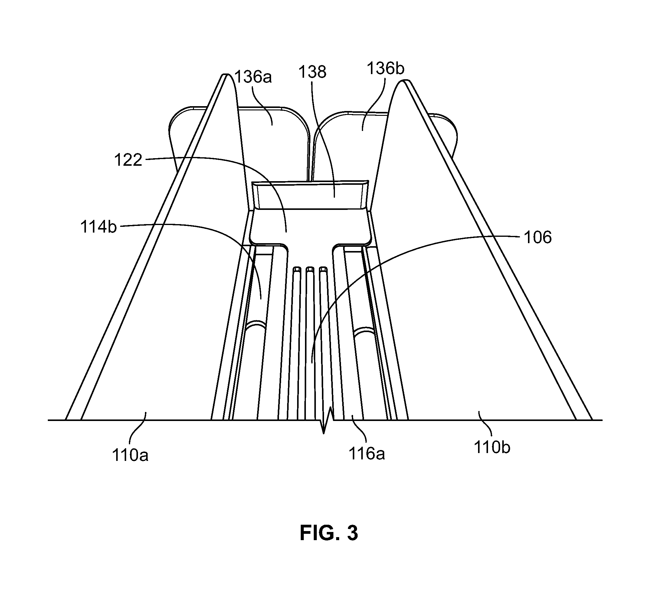
FIG. 3 depicts another isometric view of a rear section of the example product management display system of FIG. 1.
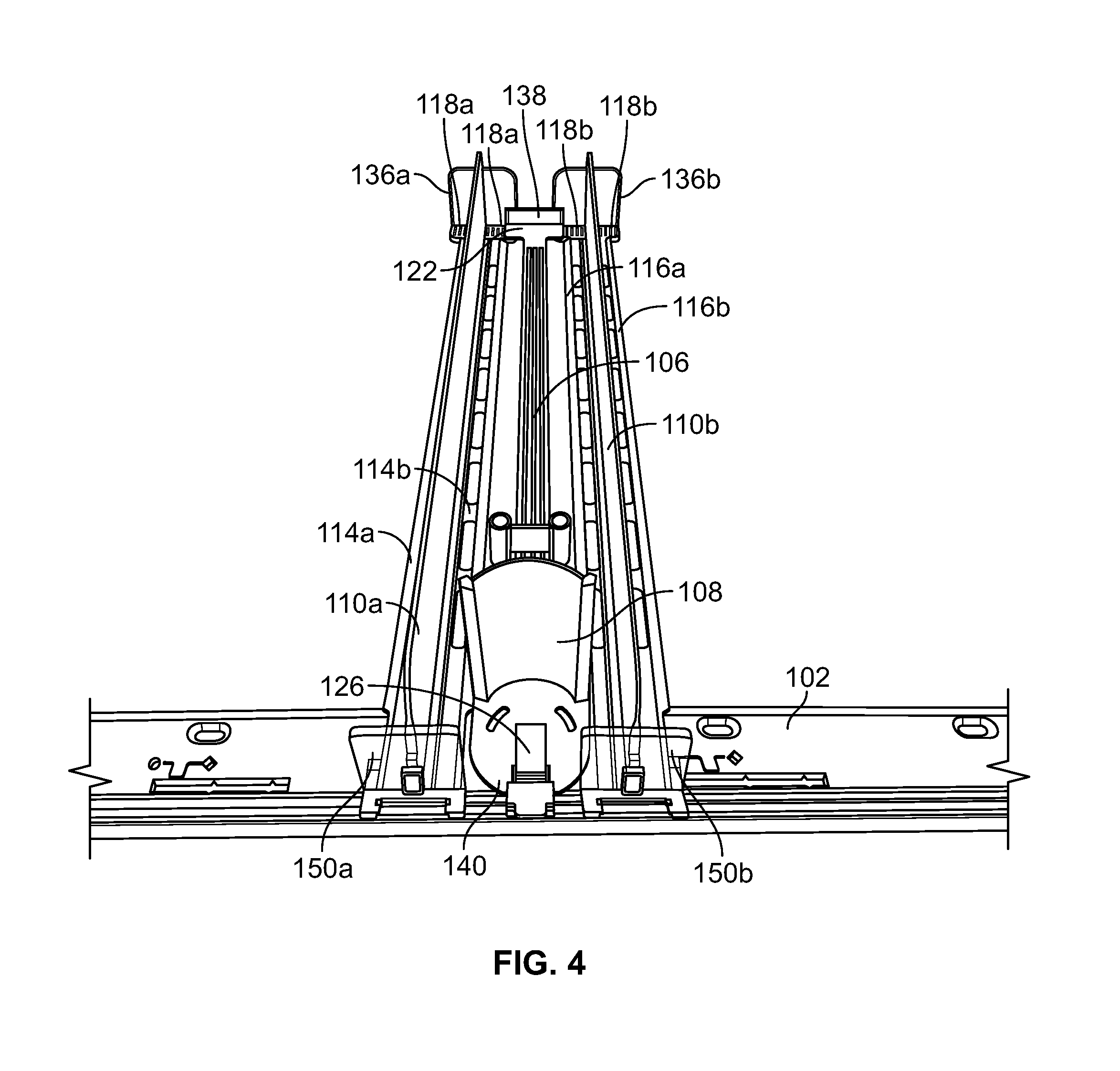
FIG. 4 depicts a front isometric view of the example product management display system of FIG. 1 in a second position.
FIG. 5 depicts another isometric view of a rear section of the example product management display system of FIG. 1 in the second position.
FIG. 6 depicts another isometric view of a bottom rear section of the floor of the example product management display system of FIG. 1.
FIG. 7a shows a side-perspective view of a front portion of an example central track.
FIG. 7b shows another side-perspective view of a front portion of the example central track of FIG. 7a.
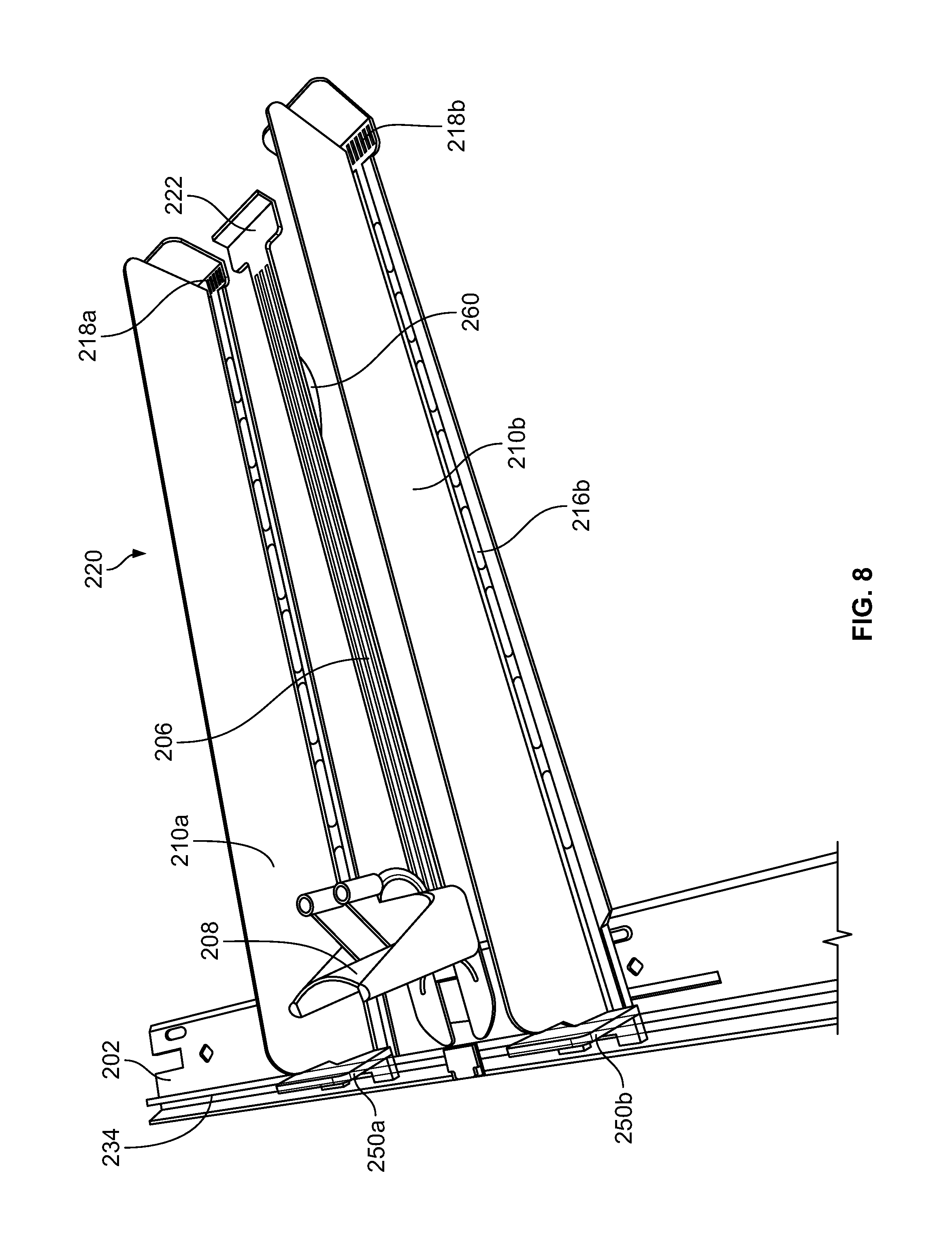
FIG. 8 shows a front perspective view of another example merchandise display system.
FIG. 9 shows a side perspective view of a rear portion of the example merchandise display system of FIG. 8.
FIG. 10 shows a rear perspective view of the example merchandise display system of FIG. 8.
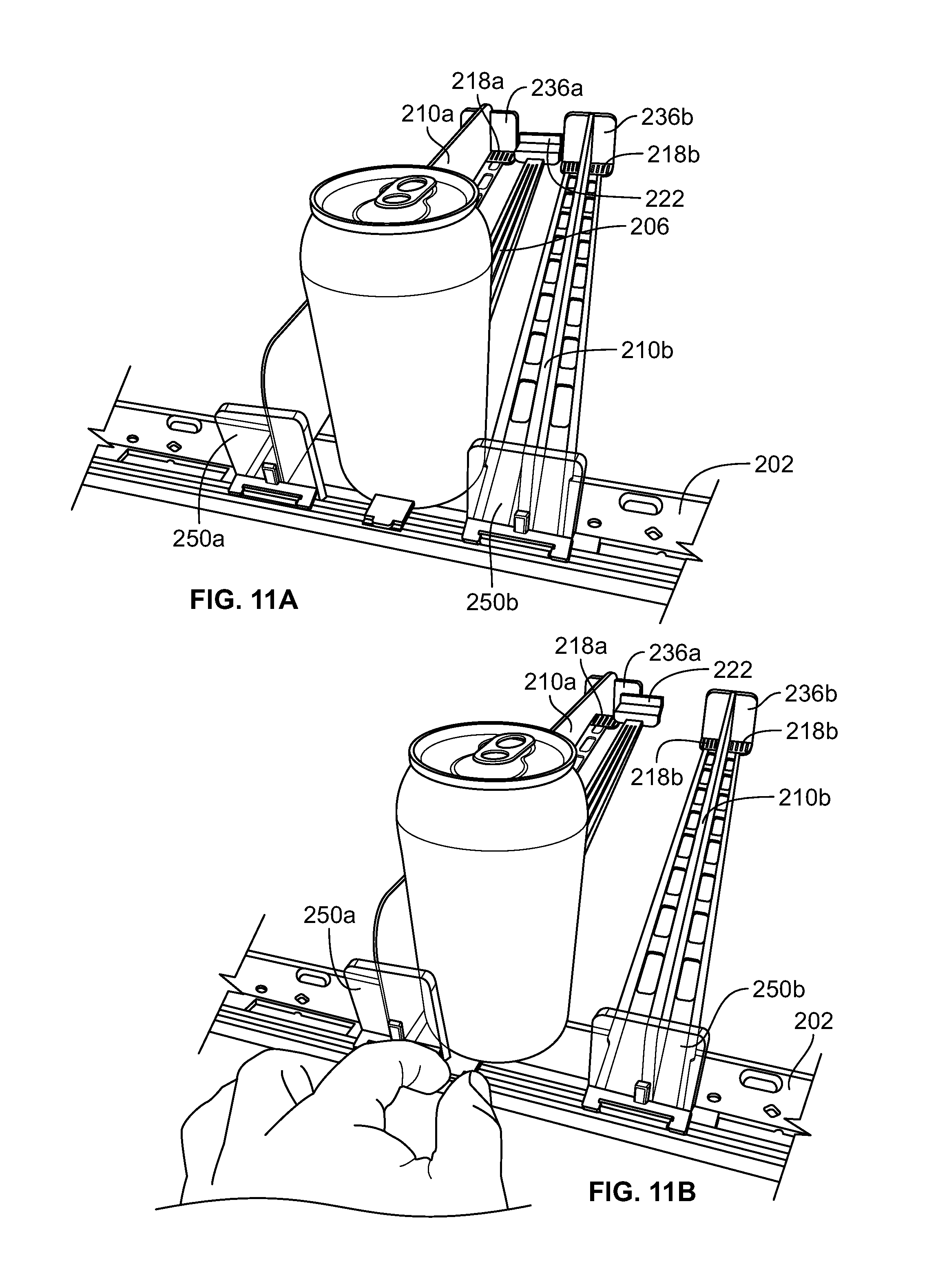
FIGS. 11a-11g depict an exemplary method of adjusting and loading the merchandise display system of FIG. 8.
Before the embodiments of the invention are explained in detail, it is to be understood that the invention is not limited in its application to the details of construction and the arrangement of the components set forth in the following description or illustrated in the drawings. The invention is capable of other embodiments and of being practiced or being carried out in various ways. Also, it is to be understood that the phraseology and terminology used herein are for the purpose of description and should not be regarded as limiting. The use of "including" and "comprising" and variations thereof is meant to encompass the items listed thereafter and equivalents thereof as well as additional items and equivalents thereof. Further, the use of the term "mount," "mounted" or "mounting" is meant to broadly include any technique or method of mounting, attaching, joining or coupling one part to another, whether directly or indirectly.
Also, while the terms "front," "back," "rear," "side," "forward," "rearward," and "backward" and the like may be used in this specification to describe various example features and elements of the invention, these terms are used herein as a matter of convenience, e.g., based on the example orientations shown in the figures and/or the orientations in typical use. Nothing in this specification should be construed as requiring a specific three dimensional or spatial orientation of structures in order to fall within the scope of the disclosure.
DETAILED DESCRIPTION
The disclosure may be embodied in various forms. Referring to the Figures wherein like numerals indicate like elements, FIGS. 1-6 depict an example anti-splay merchandising display system 100, for displaying and merchandising product to a consumer. The merchandising display system 100 is configured to display product in rows by use of divider assemblies while maintaining the spacing between the rows during dispensing of the product.
As shown in FIGS. 1, 2, and 4, the example merchandising display system 100 can include a front rail 102, identical first and second divider assemblies 110a, 110b, and a central track or floor 106 accommodating a pusher assembly 108. Product can be placed in rows between the first divider assembly 110a and the second divider assembly 110b and on the central track 106 of the merchandising display system 100. When a first product located in the front of a particular row is removed, the pusher assembly 108 advances the entire row of product remaining in the row toward first and second product barriers 150a, 150b until the next product abuts the first and second product barriers 150a, 150b. Although only two divider assemblies 110a, 110b and one central track 106 are depicted in the Figures, it is contemplated that more than two divider assemblies and multiple central tracks can be provided along the rail 102 to accommodate several rows of product.
The example merchandising display system 100 is configured to prevent splaying or separating of the divider assemblies 110a, 110b, particularly when a row of product is loaded toward the rear of the shelf. As is discussed in more detail below, the central track 106 in conjunction with the weight of the product are configured to maintain the spacing of the first divider assembly 110a and the second divider assembly 110b, to help maintain the first divider assembly 110a and the second divider assembly 110b in position on the shelf thereby helping to maintain the product organized in their respective rows on the shelf.
The merchandising display system 100 can also be configured to be adjusted to accommodate different sized product and can be positioned in any desired location along the front rail 102. In particular, the spacing between the first divider assembly 110a and the second divider assembly 110b can be adjustable relative to each other. The first divider assembly 110a, the second divider assembly 110b, and the central track 106 can each be configured to slide along the front rail 102 to any desired position, and once in the desired position can be locked into place onto the front rail 102 by way of cams 132. For example, FIGS. 1-3 show the example merchandising display system 100 in a first position to accommodate product of a first width, and FIGS. 4 and 5 show the example merchandising display system 100 in a second position to accommodate product of a second width.
The first divider assembly 110a can be provided with a first divider wall 112a separating the first divider assembly into sections to define a first pair of floors 114a, 114b, which provide a first track and a second track for supporting product on either side of the first divider wall 112a. Likewise, the second divider assembly 110b can include a second divider wall 112b separating the second divider assembly 110b into sections to define a second pair of floors 116a, 116b to provide a third track and a forth track for supporting product. Additionally, as shown in FIGS. 1-5, the central track 106 can be configured to sit on top of one of the first divider floors 114b and one of the second divider floors 116a in a position to accommodate the corresponding width of the product in the row. The central track 106 is configured to extend between the first divider assembly 110a and the second divider assembly 110b. Together the first divider floor 114b, the second divider floor 116a, and the central track 106 define a floor 130 for receiving a row of product. In one example, when positioned in the smallest setting, the floor 106, the second track 114b, and the third track 116a can form an integral surface for receiving product. However, in other settings, for example as shown in FIG. 4, the central track 106 can be spaced apart from the second track 114b and the third track 116a.
The central track 106 can include an outwardly extending flange or tail 122. The outwardly extending flange 122 engages the first divider assembly 110a at the first divider assembly rear and the floor 106 engages the second divider assembly 110b at the second divider assembly rear to prevent the first divider assembly 110a and the second divider assembly 110b from splaying in relation to one another. This helps to maintain the product neatly in rows on the shelves in between the first divider wall 112a of the first divider assembly 110a and the second divider wall 112b of the second divider assembly 110b.
In one example, the rear portion of each of a first pair of floors 114a, 114b of the first divider assembly 110a and the rear portion of each of the second pair of floors 116a, 116b of the second pair of floors 116a, 116b of the second divider assembly 110b can be provided with a plurality of notches 118a, 118b for accommodating various different sized product. The notches are configured to receive corresponding projections 120a, 120b on the flange of the central track 106.
As shown in FIG. 6, the flange or tail 122 on the central track 106 can include a first tooth or projection 120a and a second tooth or projection 120b. Both the first projection 120a and the second projection 120b can be oriented vertically on the flange 122. The first projection 120a can be configured to align with and rest within one of the plurality of notches 118a on the second track 114b on the first divider assembly 110a. Similarly, the second projection 120b can be configured to align with and rest within one of the plurality of notches 118b in the third track 116a on the second divider assembly 110b.
Also as shown in FIG. 6, the central track 106 can be provided with an extended base area 154, which can be received in between the first divider assembly 110a and the second divider assembly 110b and acts as a spacing guide for the first divider assembly 110a and the second divider assembly 110b when the divider assemblies 110a, 110b are in the smallest setting. The central track 106 can be provided with a ramp 152. It is also contemplated that the flange 122 can be provided with multiple projections that can be received in multiple openings in the first divider assembly 110a and the second divider assembly 110b to provide additional traction between the central track 106, the first divider assembly 110a, and the second divider assembly 110b. This can help increase the retention forces between the central track 106, the first divider assembly 110a, and the second divider assembly 110b and the ability of the central track 106 to prevent splaying of the first divider assembly 110a and the second divider assembly 110b when product is loaded therein.
As discussed herein, the central track 106 sits on top of the one of the first pair of floors 114a, 114b of the first divider assembly 110a and one of the second pair of floors 116a, 116b of the second divider assembly 110b at their respective rear portions. The first divider assembly 110a and the second divider assembly 110b can be arranged relative to each other to the corresponding width of the product. As product is loaded from the front of the shelf, the pusher assembly 108 moves backwards on the central track 106, and the weight of the product itself causes the first projection 120a and the second projection 120b on the flange 122 of the central track 106 to engage the notches 118a, 118b of the first divider assembly 110a and the second divider assembly 110b respectively. When product is pushed toward the rear of the shelf, splaying can become more prevalent, and this configuration essentially locks the divider assemblies 110a, 110b together at the rear automatically. This example can be easier to implement in that arranging the divider assemblies simply requires that the divider assemblies 110a, 110b be oriented according to the width of the product, and the central track 10 be placed on the divider assemblies at the desired width.
In addition, the flange or tail 122 can be provided with an upstanding rear portion 138. The rear portion 138 can help to prevent product from falling off of the rear portion of the shelf. In combination with the projections 120a, 120b described above or in the alternative, although not shown, the rear portion 138 may also be provided with a series of projections that can fit within corresponding notches on the first and second rear product barriers 136a, 136b. Moreover, the rear portion 138 can also be provided with a texturized surface to also help prevent the divider assemblies 110a, 110b from splaying.
The central track 106 can also support the pusher assembly 108. The pusher assembly 108 can be any type of pusher assembly and can be configured according to the type of product that is being merchandised in the merchandising display system 100. For example, the pusher assembly 108 can be any of the pusher examples disclosed in U.S. application Ser. No. 14/611,767, incorporated by reference above. The pusher 108 can be held onto the central track 106 by only the coiled spring. Also the central track 106 can include a guide or track and the pusher assembly 108 can include a corresponding projection that engages the guide or track located on the central track 106.
In one example, the pusher assembly 108 can include a pusher floor 140, a pusher paddle 124, and a coiled spring 126 positioned behind the pusher paddle 124. The coiled spring 126 is configured to bias the pusher assembly 108 toward the front rail 102 and the barriers 150a, 150b. In this example, the pusher paddle 124 can be mounted to the central track 106 and can be configured to bias product toward a front of a shelf such that a consumer can easily remove the product from the front of the shelf.
At a front portion, each of the first divider assembly 110a, the second divider assembly 110b, and the central track 106 can be configured to connect to the front rail 102 by way of various connections. The types of connections may include a cam or lock that engages the front rail 102, which are shown and described in U.S. application Ser. No. 14/611,767, fully incorporated by reference above. In this example, the divider assemblies 110a, 110b can be provided with a separate cam 132. The cam 132 can be configured to move between a first position and a second position for selective engagement with a groove or channel 134 in the front rail 102. When the respective cam 132 is in the first position and the particular component (e.g. the first divider assembly 110a or the second divider assembly 110b) is on the rail, the particular component can be (a) movable in a lateral direction parallel to the front rail 102 and (b) secured in a direction perpendicular to the front rail 102. However, when the respective cam 132 is in the second position and the particular component is engaged with the rail, the particular component is (a) fixed in the lateral direction parallel to the front rail 102 and (b) secured in the direction perpendicular to the front rail 102.
In one example, the central track 106 can be secured to the front rail 102 by a friction-engagement-type fit that allows the central track 106 to be fixed to the front rail 102 and to also move along the front rail 102 for adjusting the product management display system 100 to receive product therein. Specifically, as shown in FIGS. 7a and 7b, the front of the central track 106 can be provided with an extension 165 having a pair of semi-ocular protrusions 162, which are configured to fit into the front rail groove or channel 134. Together the extension 165 and the semi-ocular protrusions 162 provide a frictional fit into the front rail groove or channel 134. Additionally, the extension 165 can be provided with a tab 166 for the user to grasp the front portion of the central track 106 such that the central track 106 can be placed onto, removed from, or slid along the front rail 102. The extension 165 and the semi-ocular protrusions 162 allows for user to slide the central track 106 along the front rail 102 in order to center the central track 106 once the divider assemblies 110a, 110b have been sized to the container width.
In one example, the extension 165, the semi-ocular protrusions 162, and the tab 166 can be formed of an elastomeric material, which allows for the extension 165 and the semi-ocular protrusions 162a, 162b to sufficiently flex when placed into the front rail groove or channel 134. Moreover, the front rail 102 can be formed of a flexible material, such as a suitable plastic in order to also flex when the extension 165 and the semi-ocular protrusions 162 are received within the groove 134. It is also contemplated that the central track 106 can connect to the front rail 102 using other connection methods. For example, the central track 106 can be provided with a similar cam and lock system as the divider assemblies discussed above with respect to the divider assemblies 110a, 110b for securing the central track 106 to the front rail.
Additionally, product can be prevented from sliding off of the front or the rear of the shelf. Specifically, the first and second product barriers 150a, 150b can be affixed to the first divider assembly 110a and the second divider assembly 110b respectively. Additionally, the first divider assembly 110a and the second divider assembly 110b can be provided with integral first and second rear product barriers 136a, 136b to prevent product from being displaced off of the rear of shelves.
Additionally, the merchandising display system 110 can be configured to support several rows of the same or different product. Although not shown, another central track can be placed on top of either the other of the first pair of floors 114a, 114b of the first divider assembly 110a, or another central track can be placed in on the other one of the second pair of floors 116a, 116b of the second divider assembly 110b. Furthermore, another divider assembly can be provided to accommodate the central track on the other side and can be arranged for receiving any width of product therein.
For example, in addition to the first divider assembly 110a and the second divider assembly 110b and the central track 106, a third divider assembly (not shown) and a second central track (not shown) can be configured to connect to the front rail adjacent either the first divider assembly 110a or the second divider assembly 110b. Like the first divider assembly 110a and the second divider assembly 110b, the third divider assembly can also include a third divider wall separating the third divider assembly to define a pair of floors for receiving product, i.e., a fifth track and a sixth track for supporting product. Additionally like the central track 106, the second central track can be configured to extend between the respective divider assemblies. For example, the second central track can be configured to engage the second divider assembly, and the second central track can be configured to engage the third divider assembly to provide an additional row for product. Also the second central track can be provided with a pair of notches for engaging the second divider assembly and the third divider assembly for preventing the second divider assembly and the third divider assembly from splaying in relation to one another.
FIGS. 8-11g show another example merchandising display system 200, where like numerals indicate like elements as in the example shown in FIGS. 1-7. The example merchandise display system 200 is similar to the example disclosed above in relation to FIGS. 1-6. However, in this example, the central track 206 is provided with a spring tab 260 (shown in FIGS. 8 and 9) located on the underside of the central track 206.
The spring tab 206 allows the user to freely adjust the first divider assembly 210a and the second divider assembly 210b before product is loaded in the merchandise display system 200. In particular, the spring tab 260 lifts the rear portion and flange 222 of the central track 206 to prevent the flange 222 of the central track 206 from engaging the rear portion of the first divider assembly 210a and the second divider assembly 210b when the merchandise display system 200 is in the unloaded condition. The spring tab 260 can be configured to engage the shelf floor and bias the central track 206 up off of the first divider assembly 210a and the second divider assembly 210b floors 214a, 214b, 216a, 216b, such that the first divider assembly 210a and the second divider assembly 210b can be moved relative to the central track 206. As shown in FIG. 9, the spring tab 260 can be configured to raise the central track 206 to a predetermined height H.sub.1 above the floors 214a, 214b, 216a, 216b to allow for the first divider assembly 210a and the second divider assembly 210b to be freely adjusted relative to the central track 206. Once product is loaded into the merchandise display system 200, the weight of the product pushes down on the spring tab 260 and forces the spring downwardly into a recess (not shown) located at the bottom of the central track 206, such that the flange 222 engages the floors 214b, 216a of the divider assemblies 210a, 210b to help prevent the divider assemblies 210a, 210b from splaying.
In one example, the spring tab 206 can be a spring steel leaf spring. The spring tab 260, in one example, can be integrally molded into the central track 206 or can be attached to the central track 206 by any other fastening method. The spring tab 206 may also be formed of the same material as the central track in such a way that it resiliently extends from the bottom of the central track 206 when the merchandise display system 200 is in an unloaded position. For example, the spring tab 206 can be formed as a resilient lever or projection extending at a predetermined angle, and the bottom of the central track 206 may include a recess for receiving the lever or projection when the central track 206 is loaded with product. In other examples, the spring tab 260 can be an elastomeric material that resiliently deflects when the central track 206 is loaded with product.
FIGS. 11a-11g show an exemplary method of adjusting and loading the merchandise display system 200. As shown in FIG. 11a, one row of product can be loaded in between the first divider assembly 210a and the second divider assembly 210b. In FIG. 11b, the central track 206 can be adjusted to the middle location of the product width. In FIG. 11c, with only one row of product loaded therein, the divider assemblies 210a, 210b can be moved freely underneath the rear portion of the central track 206, so that the product has just enough space to move forward in the merchandise display assembly 200. Next, the divider assemblies 210a, 210b can be locked into place on the front rail 202 in FIG. 11d. As shown in FIGS. 11e-11g as rows of product are added into the merchandise display assembly 200, the weight of the product flexes the spring tab 260 into the recess (not shown) on the bottom of the central track 206 and allows the flange 222 of the central track 206 to engage the divider assemblies 210a, 210b, which helps to secure the central track 206 and the divider assemblies 210a, 210b thereby helping to prevent splaying of the divider assemblies 210a, 210b.
Other alternative examples are contemplated for preventing splaying of the divider assemblies. For example, the flange can include slots or notches and the divider assemblies can include projections that can be received in the slots or notches in the flange. Moreover, other connection types are contemplated for connecting the divider assemblies to the central track, such as using texturized surfaces, interference fits, snap fits, ball and socket connections, threaded fasteners, hook and loop connections, elastomeric connections, adhesive connections, and the like. In addition, the flange and central track can be arranged such that the central track and flange sits below the divider assemblies. In this way when weight is placed on the divider assemblies, the divider assemblies will push down on the central track, which can help prevent the divider assemblies from splaying. Also, the flange can be located on other areas along the central track, and the divider assemblies can be provided with areas for receiving the flange, and the flange can be connected to the central track by any connection method. Moreover, a plurality of flanges can be provided on the central track. Each of the plurality of flanges can include pair of projections similar to flange 122 or can include a plurality of notches and the divider assemblies can include corresponding notches or projections for receiving the plurality of flanges. Also the flanges can include arms or upright sections for wrapping around the divider assemblies for preventing splaying. The arms or upright sections can be provided with an elastomeric material to accommodate for different sized product. In addition, the rear section of the divider assemblies can be provided with a cam lock and the rear of the shelf can be provided with a similar rail as the front rail 102 for locking the divider assemblies at their rear portions. Also the divider assemblies and shelves can be configured to removably connect at the rear portion of the divider assemblies. For example, the divider assemblies can be provided with projections that can be placed in corresponding recesses at the rear section of the shelf or can be provided with recesses for receiving corresponding projections on the shelf.
An example merchandise display system can include a front rail configured to mount to a shelf and a first divider assembly configured to connect to the front rail. The first divider assembly can include a first divider wall separating the first divider assembly to define a first track and a second track for supporting product, and the first divider assembly can define a first divider assembly front and a first divider assembly rear. The merchandise display system can also include a second divider assembly. The second divider assembly can be configured to connect to the front rail and can define a second divider assembly front and a second divider assembly rear. The second divider assembly can include a second divider wall separating the second divider assembly to define a third track and a forth track for supporting product.
The merchandise display system may also include a floor configured to connect to the front rail and can be configured to extend between the first divider wall and the second divider wall. The floor can be configured to engage the first divider assembly at the first divider assembly rear, and the floor can be configured to engage the second divider assembly at the second divider assembly rear to aid in preventing the first divider assembly and the second divider assembly from splaying in relation to one another. The floor can include a pusher assembly having a pusher paddle and a coiled spring positioned behind the pusher paddle and can be configured to bias the pusher paddle toward the front rail. The floor, the second track, and the third track can together form a surface for receiving at least one product.
In another example, the first divider assembly and the second divider assembly spacing can be adjustable. For example, each first divider section, e.g., the first track and the second track, can include a first plurality of notches, and each second divider section, e.g., the third track and the second track, can include a second plurality of notches. Also the floor can include a first projection and a second projection, and the first projection can be configured to extend into one of the first plurality of notches, and the second projection can be configured to extend into one of the second plurality of notches. The weight of the product causes the floor to engage the first divider assembly and the second divider assembly at the second divider assembly to aid in preventing the first divider assembly and the second divider assembly from splaying in relation to one another. The floor can also include a spring for raising the floor above a rear portion of the first divider assembly and a rear portion of the second divider assembly when the merchandise display system is in the unloaded position.
The merchandise display system may also include a third divider assembly. The third divider assembly can be configured to connect to the front rail and can include a third divider wall separating the third divider assembly to define a fifth track and a sixth track for supporting product. Also the merchandising assembly can include second floor, and the second floor can be configured to connect to the front rail and can be configured to extend between the second divider wall and the third divider wall. The second floor can also engage the second divider assembly and the third divider assembly to prevent the second divider assembly and the third divider assembly from splaying in relation to one another.
In another example, a method can include providing a front rail configured to connect to a shelf, providing a first divider assembly and configuring the first divider assembly to connect to the front rail. The first divider assembly can include a first divider wall and at least one first floor for supporting product. A second divider assembly can also be provided, and the method can also include configuring the second divider assembly to connect to the front rail. The second divider assembly can include a second divider wall and at least one second floor for supporting product. The method may include providing a track configured to connect to the front rail and configuring the track to extend between the first divider wall and the second divider wall. The method can also include configuring the track to engage the first divider assembly and configuring the track to engage the second divider assembly to help prevent the first divider assembly and the second divider assembly from splaying in relation to one another. The track, the at least one first floor, and the at least one second floor together form a surface for receiving at least one product.
The method can also include configuring the first divider assembly and the second divider assembly spacing to be adjustable. In addition, the method can include providing the at least one floor of the first divider assembly with a first plurality of notches, providing the at least one floor of the second divider assembly with a second plurality of notches, providing the track with a first projection and a second projection, and configuring the first projection to extend into one of the first plurality of notches and configuring the second projection to extend into one of the second plurality of notches. The method may also include providing the track with a pusher assembly having a pusher paddle and positioning a coiled spring behind the pusher paddle and configuring the coiled spring to bias the pusher paddle toward the front rail.
The method can also include providing a third divider assembly, configuring the third divider assembly to connect to the front rail, providing the third divider assembly with a third divider wall and at least one third floor for supporting product and providing a second track and configuring the second track to connect to the front rail and to extend between the second divider wall and the third divider wall. The second track can be configured to engage the second divider assembly, and the second floor can be configured to engage the third divider assembly to help prevent the second divider assembly and the third divider assembly from splaying in relation to one another.
The method may also include configuring the track to engage the first divider at a rear portion of the first divider assembly and configuring the track to engage the second divider assembly at a rear portion of the second divider assembly such that weight of product loaded on the at least one first floor, the at least one second floor, and the track aids in preventing the first divider assembly and the second divider assembly from splaying in relation to one another.
In another example, a merchandise display system can include a front rail configured to mount to a shelf and a first divider assembly configured to connect to the front rail. The first divider assembly can include a first divider assembly front and a first divider assembly rear. The first divider assembly can include a first divider wall separating the first divider assembly to define a first track and a second track for supporting product. The first track and the second track can include a first plurality of notches. The merchandise system may also include a second divider assembly defining a second divider assembly front and a second divider assembly rear. The second divider assembly can be configured to connect to the front rail, and the second divider assembly can include a second divider wall separating the second divider assembly to define a third track and a forth track for supporting product. The third track and the forth track can include a second plurality of notches.
A floor can be configured to connect to the front rail and can be configured to extend between the first divider wall and the second divider wall. The floor can include a first projection and a second projection. Additionally, the floor can engage the first divider assembly at the first divider assembly rear, and the floor can engage the second divider assembly at the second divider assembly rear such that the first projection extends into one of the first plurality of notches and the second projection extends into one of the second plurality of notches to aid in preventing the first divider assembly and the second divider assembly from splaying in relation to one another. The first plurality of notches, the second plurality of notches and the corresponding first and second projections allows for the first divider assembly and the second divider assembly spacing to be adjustable.
The floor can also include a pusher assembly having a pusher paddle and a coiled spring positioned behind the pusher paddle that is configured to bias the pusher paddle toward the front rail. The floor, the second track, and the third track can together form a surface for receiving at least one product.
The merchandise display system can also include a third divider assembly, and the third divider assembly can be configured to connect to the front rail. The third divider assembly can include a third divider wall separating the third divider assembly to define a fifth track and a sixth track for supporting product. The merchandise display system can also include a second floor, and the second floor can be configured to connect to the front rail and can be configured to extend between the second divider wall and the third divider wall. Also the second floor can be configured to engage the second divider assembly and the third divider assembly to help prevent the second divider assembly and the third divider assembly from splaying in relation to one another. Additionally the weight of the product can cause the floor to forcefully engage the first divider assembly and the second divider assembly at the second divider assembly to aid in preventing the first divider assembly and the second divider assembly from splaying in relation to one another.
Variations and modifications of the foregoing are within the scope of the present disclosure. For example, one of skill in the art will understand that multiples of the described components may be used in stores and in various configurations. The present disclosure is therefore not to be limited to a single system, nor the upright pusher configuration, depicted in the Figures, as the system is simply illustrative of the features, teachings and principles of the disclosure. It should further be understood that the disclosure defined herein extends to all alternative combinations of two or more of the individual features mentioned or evident from the text and/or drawings. All of these different combinations constitute various alternative aspects of the present disclosure. The embodiments described herein explain the best modes known for practicing the disclosure and will enable others skilled in the art to utilize the disclosure.
* * * * *
D00000
D00001
D00002
D00003
D00004
D00005
D00006
D00007
D00008
D00009
D00010
D00011
D00012
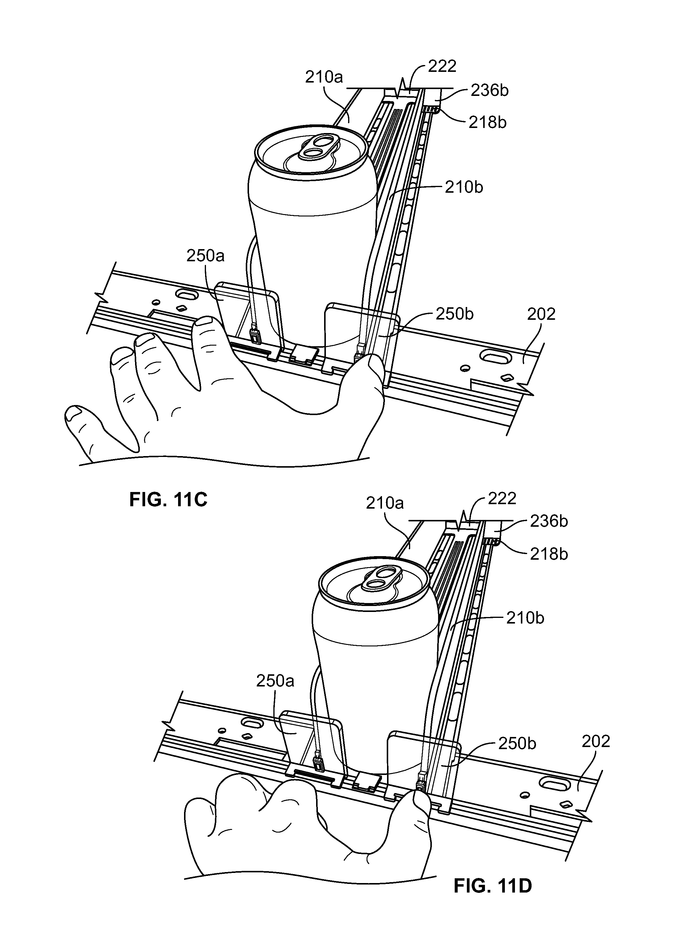
D00013

D00014

XML
uspto.report is an independent third-party trademark research tool that is not affiliated, endorsed, or sponsored by the United States Patent and Trademark Office (USPTO) or any other governmental organization. The information provided by uspto.report is based on publicly available data at the time of writing and is intended for informational purposes only.
While we strive to provide accurate and up-to-date information, we do not guarantee the accuracy, completeness, reliability, or suitability of the information displayed on this site. The use of this site is at your own risk. Any reliance you place on such information is therefore strictly at your own risk.
All official trademark data, including owner information, should be verified by visiting the official USPTO website at www.uspto.gov. This site is not intended to replace professional legal advice and should not be used as a substitute for consulting with a legal professional who is knowledgeable about trademark law.