Pellicle Adhesive Residue Removal System And Methods
WU; Banqiu ; et al.
U.S. patent application number 16/448722 was filed with the patent office on 2020-01-30 for pellicle adhesive residue removal system and methods. The applicant listed for this patent is Applied Materials, Inc.. Invention is credited to Eli DAGAN, Banqiu WU.
| Application Number | 20200033740 16/448722 |
| Document ID | / |
| Family ID | 69177330 |
| Filed Date | 2020-01-30 |
| United States Patent Application | 20200033740 |
| Kind Code | A1 |
| WU; Banqiu ; et al. | January 30, 2020 |
PELLICLE ADHESIVE RESIDUE REMOVAL SYSTEM AND METHODS
Abstract
Embodiments of the present disclosure generally include apparatus and methods for removing adhesive residues from a surface of a lithography mask. In particular, the processing systems described herein provide for the delivery of a solvent to a discrete plurality of locations on the surface of the lithography mask to facilitate the removal of adhesive residue therefrom. In one embodiment, a method of processing a substrate includes positioning the substrate on a substrate support of a processing system, sealing individual ones of a plurality of cleaning units to a surface of the substrate at a corresponding plurality of locations, heating a cleaning fluid to a temperature between about 50.degree. C. and about 150.degree. C., flowing the cleaning fluid to, and thereafter, from, the plurality of cleaning units, and exposing the surface of the substrate to the cleaning fluid at the plurality of locations.
| Inventors: | WU; Banqiu; (San Jose, CA) ; DAGAN; Eli; (Sunnyvale, CA) | ||||||||||
| Applicant: |
|
||||||||||
|---|---|---|---|---|---|---|---|---|---|---|---|
| Family ID: | 69177330 | ||||||||||
| Appl. No.: | 16/448722 | ||||||||||
| Filed: | June 21, 2019 |
Related U.S. Patent Documents
| Application Number | Filing Date | Patent Number | ||
|---|---|---|---|---|
| 62703239 | Jul 25, 2018 | |||
| Current U.S. Class: | 1/1 |
| Current CPC Class: | G03F 1/62 20130101; H01L 21/02082 20130101; G03F 1/82 20130101; H01L 21/6708 20130101; G03F 7/70983 20130101; H01L 21/67028 20130101; G03F 7/70925 20130101; B08B 3/10 20130101 |
| International Class: | G03F 7/20 20060101 G03F007/20; B08B 3/10 20060101 B08B003/10; H01L 21/67 20060101 H01L021/67; H01L 21/02 20060101 H01L021/02 |
Claims
1. A method of processing a substrate, comprising: positioning a substrate on a substrate support of a processing system; sealing individual ones of a plurality of cleaning units to a surface of the substrate at a corresponding plurality of locations; heating a cleaning fluid to a temperature between about 50.degree. C. and about 150 C.; flowing the cleaning fluid to, and subsequently thereafter, from, the plurality of cleaning units; and exposing the surface of the substrate to the cleaning fluid at the plurality of locations.
2. The method of claim 1, wherein the cleaning fluid comprises one of dimethyl sulfoxide, 1-phenoxypropan-2-ol, 1-methyl-2-pyrrolidinonem, 2-phenoxyethanolm, 4-nonylphenol, dichloromethane, dimethylformamide, dichloromethane, methanol, petroleum distillate, or a combination thereof.
3. The method of claim 1, wherein the substrate comprises a multilayer stack comprising a plurality of repeating metal and silicon layers; and a patterned absorber layer disposed on the multilayer stack.
4. The method of claim 1, wherein the processing system comprises: the substrate support disposed in a processing volume; and a fluid distribution assembly facing a substrate receiving surface of the substrate support, the fluid distribution assembly comprising: a distribution shaft having an inlet and an outlet; a manifold coupled to the distribution shaft; and the plurality of cleaning units coupled to the manifold.
5. The method of claim 4, wherein each of the plurality of cleaning units comprises: a first conduit; a second conduit disposed in the first conduit, wherein an end of the second conduit is recessed from an end of the first conduit; and a gasket disposed on the end of the first conduit.
6. The method of claim 5, wherein the first conduit and the second conduit define a portion of a fluid flow pathway which extends from the inlet to the outlet of the distribution shaft.
7. The method of claim 5, wherein sealing individual ones of the plurality of cleaning units to the surface of the substrate comprises raising the substrate support until the gaskets disposed of each of the cleaning units sealingly contact the surface of the substrate.
8. The method of claim 5 wherein sealing the fluid dispensing portion of a plurality of cleaning units to the surface of the substrate comprises lowering the fluid distribution assembly until the gaskets disposed on of each of the cleaning units sealingly contact the surface of the substrate.
9. A computer readable medium having instructions stored thereon for: a method of processing a substrate, comprising: positioning the substrate on a substrate support of a processing system; sealing a plurality of cleaning units to a surface of the substrate at a corresponding plurality of locations; heating a cleaning fluid to a temperature between about 50.degree. C. and about 150 C.; flowing the cleaning fluid to, and thereafter, from, the plurality of cleaning units; and exposing the surface of the substrate to the cleaning fluid at the plurality of locations.
10. The computer readable medium of claim 9, wherein the processing system comprises: the substrate support disposed in a processing volume; and a fluid distribution assembly facing a substrate receiving surface of the substrate support, the fluid distribution assembly comprising: a distribution shaft having an inlet and an outlet; a manifold coupled to the distribution shaft; and the plurality of cleaning units coupled to the manifold.
11. The computer readable medium of claim 10, wherein one or more of the plurality of cleaning units comprises: a first conduit; a second conduit disposed in the first conduit, wherein an end of the second conduit is recessed from an end of the first conduit; and a gasket disposed on the end of the first conduit.
12. The computer readable medium of claim 11, wherein the first conduit and the second conduit define a portion of a fluid flow pathway which extends from the inlet to the outlet of the distribution shaft.
13. The method of claim 12, wherein sealing individual ones of the plurality of cleaning units to the surface of the substrate comprises raising the substrate support until the gaskets disposed of each of the cleaning units sealingly contact the surface of the substrate.
14. The method of claim 12, wherein sealing the fluid dispensing portion of a plurality of cleaning units to the surface of the substrate comprises lowering the fluid distribution assembly until the gaskets disposed on of each of the cleaning units sealingly contact the surface of the substrate.
15. A processing system, comprising: a substrate support disposed in a processing volume; and a fluid distribution assembly facing a substrate receiving surface of the substrate support, the fluid distribution assembly comprising: a distribution shaft having an inlet and an outlet; a manifold coupled to the distribution shaft; and a plurality of cleaning units coupled to the manifold, wherein each of the plurality of cleaning units become sealed to a to-be-processed substrate when the substrate support and the fluid distribution assembly are disposed in a substrate processing mode.
16. The processing system of claim 15, further comprising a support shaft, wherein the substrate support is disposed on the support shaft, and wherein the support shaft is movably disposed through a base of the processing system.
17. The processing system of claim 15, further comprising an actuator coupled to the distribution shaft.
18. The processing system of claim 15, further comprising a fluid heater disposed in fluid communication with the inlet of the distribution shaft.
19. The processing system of claim 15, wherein one or more of the plurality of cleaning units comprises: a first conduit; a second conduit disposed in the first conduit, wherein an end of the second conduit is recessed from an end of the first conduit; and a gasket disposed on the end of the first conduit.
20. The processing system of claim 19, wherein the first conduit and the second conduit define a portion of a fluid flow pathway which extends from the inlet to the outlet of the distribution shaft.
Description
CROSS-REFERENCE TO RELATED APPLICATIONS
[0001] This application claims priority to U.S. Provisional Application Ser. No. 62/703,239 filed on Jul. 25, 2018, which is herein incorporated by reference in its entirety.
BACKGROUND
Field
[0002] Embodiments described herein generally relate to the field of semiconductor device manufacturing, and in particular, to methods and apparatus used remove adhesive residues from a surface of a lithography mask.
Description of the Related Art
[0003] Semiconductor device manufacturing typically includes forming a plurality of interconnected patterned material layers on, over, and in the surface of a workpiece, e.g., a silicon wafer. Each of the patterned material layers are formed using a series of manufacturing processes which include patterning the workpiece surface or previously deposited material layers disposed on the workpiece surface. Often, the workpiece surface or the previously deposited material layers disposed on the workpiece surface are patterned using a lithography process. A typical lithography process includes transferring a pattern formed on the surface of a lithography mask to a resist layer coating the workpiece surface or the coating previously deposited material layers disposed thereon.
[0004] A lithography mask assembly, used in a lithography process, typically includes the lithography mask and a protective pellicle disposed over the patterned surface thereof. The pellicle includes a thin transparent membrane, i.e., a pellicle membrane which extends over the patterned surface of the lithography mask when the pellicle is secured thereto. The pellicle membrane is typically mounted on a pellicle frame which is secured to the patterned surface of the lithography mask by an adhesive, such as an epoxy resin. The pellicle membrane protects the patterned surface of the lithography mask from being contacted and thereby scratched during handling, and from exposure to environmental contaminants, such as dust. Typically, the pellicle membrane is spaced apart from the surface of the lithography mask by the pellicle frame so that any particles, e.g., dust, which become collected thereon are not in a field of focus when the lithography mask pattern is transferred to the resist layer on the substrate.
[0005] Pellicles desirably extend the useful lifetime of a lithography mask and are commonly replaced during cleaning or refurbishment processes related thereto. Typically, the used pellicle is separated from a lithography mask and discarded prior to cleaning or refurbishment of the lithography mask. Residues from the adhesive used to secure the used pellicle frame to the lithography mask surface are often removed before subsequent cleaning of the patterned surface of the mask to prevent undesirable transfer of the adhesive residue thereto. Unfortunately, the relatively low volatility adhesives suitable for use with for the next generation of vacuum extreme ultra violet (EUV) lithography systems, have proven difficult to remove from EUV lithography mask surfaces without causing damage thereunto.
[0006] Accordingly, there is a need in the art for improved systems and methods for removing adhesive from the surface of a lithography mask.
SUMMARY
[0007] Embodiments of the present disclosure generally include apparatus and methods for removing adhesive residues from a surface of a lithography mask prior to cleaning or refurbishment of the lithography mask. In particular, the processing systems described herein provide for the delivery of a solvent to selective locations on the surface of the lithography mask to facilitate the removal of adhesive residue therefrom.
[0008] In one embodiment, a method of processing a substrate includes positioning the substrate on a substrate support of a processing system, sealing individual ones of a plurality of cleaning units to a surface of the substrate at a corresponding plurality of locations, heating a cleaning fluid to a temperature between about 50.degree. C. and about 150.degree. C., flowing the cleaning fluid to, and thereafter, from, the plurality of cleaning units, and exposing the surface of the substrate to the cleaning fluid at the plurality of locations.
[0009] In another embodiment, a computer readable medium has instructions stored thereon for a method of processing a substrate. The method includes positioning the substrate on a substrate support of a processing system, sealing individual ones of a plurality of cleaning units to a surface of the substrate at a corresponding plurality of locations, heating a cleaning fluid to a temperature between about 50.degree. C. and about 150.degree. C., flowing the cleaning fluid to, and thereafter, from, the plurality of cleaning units, and exposing the surface of the substrate to the cleaning fluid at the plurality of locations.
[0010] In another embodiment, a processing system includes a substrate support disposed in a processing volume and a fluid distribution assembly facing a substrate receiving surface of the substrate support. The fluid distribution assembly includes a support shaft having an inlet and an outlet, a manifold coupled to the support shaft, and a plurality of cleaning units coupled to the manifold. Here, individual ones of the cleaning units become sealed to a to-be-processed substrate when the substrate support and the fluid distribution assembly are disposed in a substrate processing mode.
BRIEF DESCRIPTION OF THE DRAWINGS
[0011] So that the manner in which the above recited features of the present disclosure can be understood in detail, a more particular description of the disclosure, briefly summarized above, may be had by reference to embodiments, some of which are illustrated in the appended drawings. It is to be noted, however, that the appended drawings illustrate only typical embodiments of this disclosure and are therefore not to be considered limiting of its scope, for the disclosure may admit to other equally effective embodiments.
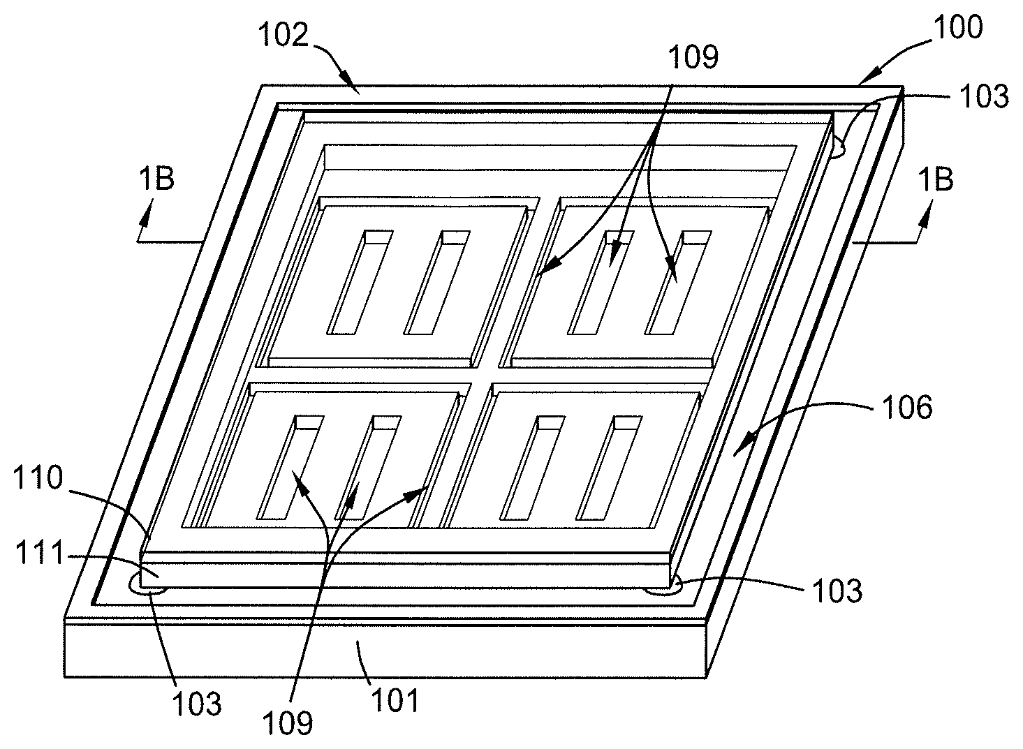
[0012] FIG. 1A is a schematic isometric view of an exemplary photomask assembly, according to one embodiment.
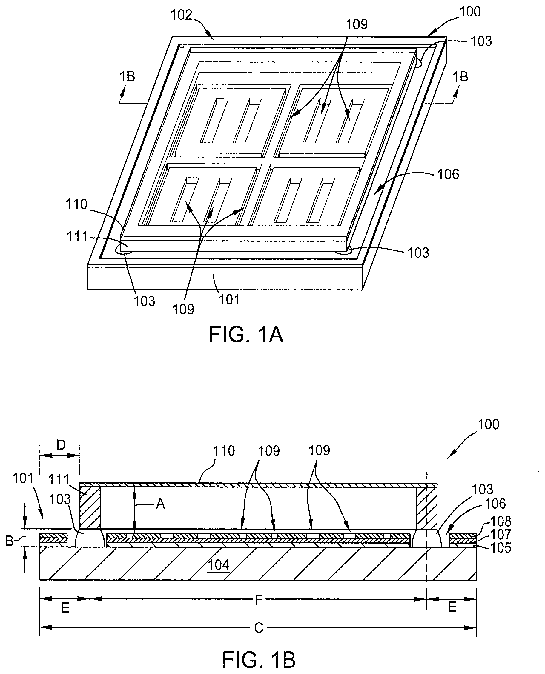
[0013] FIG. 1B is a cross-sectional view of the photomask assembly shown in FIG. 1A taken along line 1B-1B.
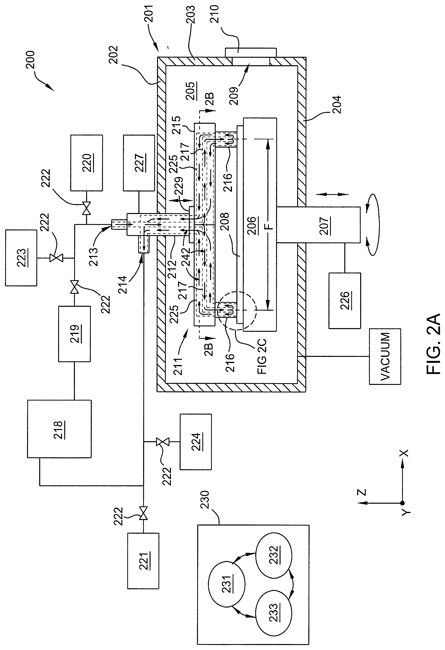
[0014] FIG. 2A is a schematic cross-sectional view of a processing system configured to practice the methods set forth herein, according to one embodiment.
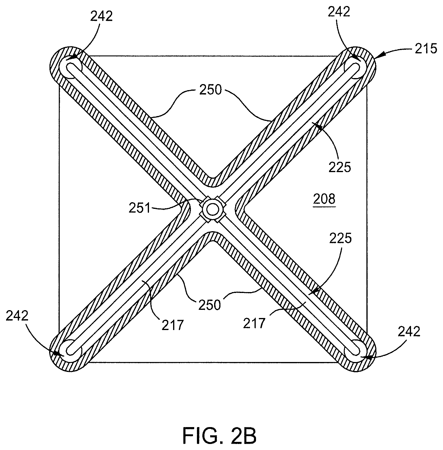
[0015] FIG. 2B is a sectional view of the fluid distribution assembly shown in FIG. 2A taken along line 2B-2B, according to one embodiment.
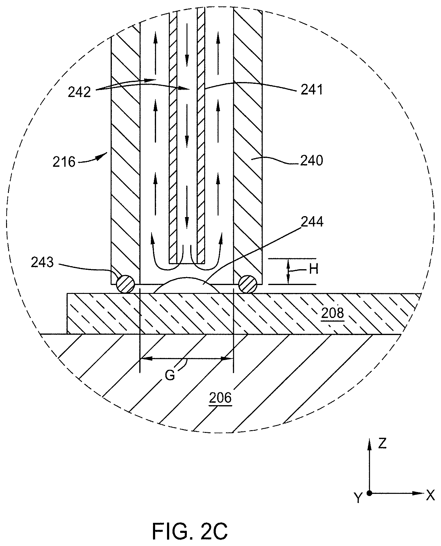
[0016] FIG. 2C is a close up view in cross section of a portion of the processing system shown in FIG. 2A, according to one embodiment.
[0017] FIG. 3 is a flow diagram setting forth a method of cleaning adhesive residue from the surface of a substrate, according to one embodiment.
[0018] To facilitate understanding, identical reference numerals have been used, where possible, to designate identical elements that are common to the figures. It is contemplated that elements and features of one embodiment may be beneficially incorporated in other embodiments without further recitation.
DETAILED DESCRIPTION
[0019] Embodiments of the present disclosure generally include apparatus and methods for removing adhesive residues from a surface of a lithography mask prior to cleaning or refurbishing of the lithography mask. In particular, the processing systems described herein provide for the delivery of a solvent to selective locations on the surface of the lithography mask to facilitate the removal of adhesive residue therefrom.
[0020] FIG. 1A is a schematic isometric view of an exemplary lithography mask assembly, according to one embodiment. FIG. 1B is a schematic cross-sectional view of the lithography mask assembly in FIG. 1A taken along line 1B-1B. Typically, the lithography mask assembly 100 includes a lithography mask 101 and a pellicle 102 secured thereto by a plurality of adhesive patches 103 interposed therebetween. In some embodiments the lithography mask 101 is configured for use with an extreme ultra violet (EUV) lithography processing system and features a substrate 104, a reflective multilayer stack 105 disposed on the substrate 104, a capping layer 107 disposed on the reflective multilayer stack 105, and an absorber layer 108 disposed on the capping layer 107. In some embodiments, the substrate 104 comprises a low thermal expansion material (LTEM), such as a titanium doped fused silica. In some embodiments, the reflective multilayer stack 105 comprises a plurality of repeating metal and silicon layers, such as a plurality of repeating Mo and Si layers, i.e., a plurality of Mo/Si layers. In some embodiments, the reflective multilayer stack 105 comprises more than about 40 alternating layers of metal and silicon and has a thickness of between about 200 nm and about 250 nm. In some embodiments, the absorber layer 108 is formed of a material comprising tantalum (Ta), such as a TaBO layer, a TaBN layer, or multilayer stack thereof, for example a TaBO layer disposed on a TaBN layer. In some embodiments, the absorber layer 108 has a thickness between about 50 nm and about 80 nm. In some embodiments, the capping layer 107 is formed of ruthenium (Ru) and has a thickness between about 1 nm and about 5 nm, for example about 2.5 nm.
[0021] Here, the absorber layer 108, having a plurality of openings 109 formed therethrough, forms a patterned surface of the lithography mask 101. Here, individual ones of the openings 109 extend through the absorber layer 108 to expose the capping layer 107 disposed therebeneath. In other embodiments, individual ones of the openings 109 further extend through the capping layer 107 to expose the reflective multilayer stack 105 disposed therebeneath. In some embodiments, the lithography mask 101 comprises one or more black-border openings 106, i.e., one or more openings extending through the absorber layer 108, the capping layer 107, and the reflective multilayer stack 105.
[0022] Typically, the pellicle 102 includes a thin (e.g., <200 nm in thickness) transparent membrane, herein a pellicle membrane 110, extending across a pellicle frame 111 and secured thereto by an adhesive layer (not shown) interposed therebetween. Herein, the pellicle membrane 110 is spaced apart from the surface of the lithography mask 101 by a distance A. The pellicle frame 111 is spaced apart from the surface of the lithography mask 101 by a thickness of the adhesive patches 103, herein a distance B of less than about 1 mm, such as between about 10 .mu.m and about 500 .mu.m. Here, the adhesive patches 103 are disposed directly on the surface of the substrate 104. In other embodiments, the adhesive patches 103 are disposed directly on the surface of the reflective multilayer stack 105. In other embodiments, the adhesive patches 103 are disposed directly on the surface of the absorber layer 108.
[0023] Spacing of the pellicle membrane 110 from the surface of the lithography mask 101 desirably prevents particles, e.g., dust, which become collected thereon from being in the field of focus when the lithography mask pattern is transferred to a resist layer on a workpiece. Spacing the pellicle frame 111 from the surface of the lithography mask desirably allows clean gas, e.g., air, to flow between the pellicle and the lithography mask. The free flow of gas between the pellicle and the lithography mask desirably prevents unequal pressures on the opposite surface of the membrane during a vacuum EUV lithography process which could cause the fragile pellicle membrane 110 to rupture. In embodiments herein, the adhesive patches 103 used to secure the pellicle 102 to the surface of the lithography mask 101 are disposed in patches at a discrete plurality of locations, such as proximate to the corners of the pellicle frame 111. For example, in some embodiments the lithography mask has a square shape in cross section where each side of the lithography mask has a length C of between about 100 mm and about 300 mm, for example about 150 mm. The sides of the pellicle frame 111 are disposed inwardly of the sides of the lithography mask 101 by a distance D of between about 0 mm and about 30 mm when measured at angles orthogonal thereto. Here, the plurality of adhesive patches 103 are disposed at the corners of the frame and have a center to center spacing F between about 70 mm and about 140 mm.
[0024] The pellicle 102, including the pellicle frame 111, is often replaced during the useful lifetime of the lithography mask 101 due to accumulation of particles on the front side and backside surfaces of the pellicle membrane 110, damage thereunto, or during other repair or refurbishment processing of the lithography mask 101. When a used pellicle 102 is removed from the surface of the lithography mask 101 at least some undesirable residue from the adhesive patches 103 will remain on the surface of the lithography mask at a discrete plurality of locations corresponding thereto. Unfortunately, the undesirable residue remaining on the surface of the lithography mask will transfer to other regions of the surface of the lithography mask during subsequent cleaning or refurbishment processes. Undesirably transferred residue may render the mask unusable or increase the cost and complexity of cleaning or refurbishing the mask. Further, unremoved residue can result in undesirable variation in the distance A between the lithography mask surface and the membrane of a subsequently mounted pellicle causing process defects related thereto or rendering the refurbished mask assembly unusable. Therefore, embodiments herein provide a processing system, described in FIGS. 2A-2C, and methods, set forth in FIG. 3, which facilitate removal of the undesirable adhesive residue from a plurality of selected locations on a lithography mask.
[0025] FIG. 2A is a schematic cross-sectional view of a processing system configured to practice the methods set forth herein, according to one embodiment. FIG. 2B is a sectional view of the fluid distribution assembly shown in FIG. 2A taken along line 2B-2B, according to one embodiment. FIG. 2C is a close up view in cross section of a portion of the processing system shown in FIG. 2A, according to one embodiment.
[0026] Herein, the processing system 200 includes a body 201, a lid 202, one or more sidewalls 203, and a base 204 which collectively define the boundaries of a processing volume 205. A substrate support 206 disposed in the processing volume 205 is disposed on a support shaft 207 extending through the base 204. The processing system 200 is configured to facilitate transferring of a substrate 208, such as the lithography mask 101 described in FIGS. 1A-1B, to and from the substrate support 206 through an opening 209 in the one or more sidewalls 203. In some embodiments, the opening 209 is sealed with a door 210 during substrate processing.
[0027] Herein, the processing system 200 further includes a fluid distribution assembly 211 disposed above the substrate support 206. The fluid distribution assembly 211 features a fluid distribution shaft 212, a manifold 215 coupled to the fluid distribution shaft 212, and a plurality of cleaning units 216 coupled to the manifold 215. In some embodiments, such as in embodiments where the processing volume is maintained in a vacuum condition, the fluid distribution shaft 212 is sealingly disposed through the lid 202. For example, in some embodiments a bellows (not shown) surrounds the fluid distribution shaft 212 inside or outside of the processing volume 205. In some of those embodiments, the processing volume 205 is fluidly coupled to a vacuum, such as to one or more dedicated vacuum pumps.
[0028] Here, fluids enter the fluid distribution assembly 211 through an inlet 213 and exits the fluid distribution assembly 211 through an outlet 214. The manifold 215 distributes fluids received through the inlet 213 to the plurality of cleaning units 216 using a plurality of distribution conduits 217 disposed in fluid communication therebetween. The manifold 215 further directs fluids received back from the plurality of cleaning units 216 to the outlet 214 using a plurality of return conduits 225 disposed in fluid communication therebetween.
[0029] In some embodiments, the manifold 215 comprises a plurality of arms 250 (shown in FIG. 2B) which extend radially from a center axis thereof to the respective plurality of cleaning units 216. Here, each of the plurality of arms 250 have a return conduit 225 formed therein and a distribution conduit 217, such as a tube having an opening formed therethrough, disposed in the return conduit 225. In other embodiments, the manifold 215 is of any other suitable shape to facilitate fluid communication between the plurality of cleaning units 216 and the distribution shaft through the plurality of distribution conduits 217 and return conduits 225 respectively disposed and formed therein. In some embodiments, the inlet 213 comprises a tube having an opening disposed therethrough and the plurality of distribution conduits 217 are fluidly coupled to the inlet 213 using a spider fitting 251 (shown in FIG. 2B).
[0030] Here, the plurality of cleaning units 216 (further described in FIG. 2C) are positioned over a corresponding plurality of locations on the surface of the substrate 208. Here, each of the plurality of locations have a to-be-removed adhesive residue 244 (shown in FIG. 2C) disposed thereon. Herein, the plurality of cleaning units 216 and are sealed to the surface of the substrate 208 when the components in the processing system 200 are disposed in a substrate processing mode (as shown). Positioning the components in a substrate processing mode comprises one or both of raising the support shaft 207 or lowering the fluid distribution shaft 212 using one or both of a first actuator 226 or a second actuator 227 respectively coupled thereto. In some embodiments, the fluid distribution shaft 212 is sealingly coupled to the manifold 215 using a flexible coupling 229, such as a gimbal coupling, to facilitate sealing of the plurality of cleaning units to the substrate 208.
[0031] In some embodiments, the support shaft 207 is rotatable about a vertical axis disposed therethrough. In those embodiments, positioning the components in a substrate processing mode includes rotating the support shaft until the adhesive residue patches disposed on the substrate are desirably aligned with the plurality of cleaning units 216.
[0032] Here, the inlet 213 is fluidly coupled to one or more fluid sources, such as a cleaning fluid source 218, i.e., a solvent, a rinse fluid source 220, such as deionized water or isopropyl alcohol (IPA), and a drying gas source 223, such as clean dry air (CDA) or N.sub.2. Cleaning fluid, rinse fluid, and drying gas from the respective fluid sources 218, 220, and 223 are selectively delivered to the inlet 213 using valves 222 disposed on the conduits fluidly coupled between the fluid source and the inlet 213, or a conduit leading to inlet 213. In some embodiments, the processing system 200 further includes a heater 219 disposed between and fluid communication with, the cleaning fluid source 218 and the inlet 213. In some embodiments, the cleaning fluid source 218 is a container and the cleaning fluid is recirculated thereinto from the outlet 214. In some embodiments, the heater 219 is a water bath or an oil bath having the cleaning fluid container disposed therein, or a shell and tube type heat exchanger. In some embodiments, rinse fluid or drying gas are respectively directed from the outlet 214 to a drain 224 or an exhaust 221 using the valves 222 disposed on the conduits fluidly coupled therebetween.
[0033] Typically, operation and control of the processing system 200 is facilitated using a system controller 230 coupled thereto. The system controller 230 includes a programmable central processing unit (CPU 231) that is operable with a memory 232 (e.g., non-volatile memory) and support circuits 233. The support circuits 233 are conventionally coupled to the CPU 231 and comprise cache, clock circuits, input/output subsystems, power supplies, and the like, and combinations thereof coupled to the various components of the processing system 200, to facilitate control thereof. The CPU 231 is one of any form of general purpose computer processor used in an industrial setting, such as a programmable logic controller (PLC), for controlling various components and sub-processors of the processing system 200. The memory 232, coupled to the CPU 231, is non-transitory and is typically one or more of readily available memories such as random access memory (RAM), read only memory (ROM), floppy disk drive, hard disk, or any other form of digital storage, local or remote.
[0034] Here, the memory 232 is in the form of a computer-readable storage media containing instructions (e.g., non-volatile memory), that when executed by the CPU 231, facilitates the operation of the processing system 200. The instructions in the memory 232 are in the form of a program product such as a program that implements the methods of the present disclosure. The program code may conform to any one of a number of different programming languages. In one example, the disclosure may be implemented as a program product stored on computer-readable storage media for use with a computer system. The program(s) of the program product define functions of the embodiments (including the methods described herein).
[0035] Illustrative computer-readable storage media include, but are not limited to: (i) non-writable storage media (e.g., read-only memory devices within a computer such as CD-ROM disks readable by a CD-ROM drive, flash memory, ROM chips or any type of solid-state non-volatile semiconductor memory) on which information is permanently stored; and (ii) writable storage media (e.g., floppy disks within a diskette drive or hard-disk drive or any type of solid-state random-access semiconductor memory) on which alterable information is stored. Such computer-readable storage media, when carrying computer-readable instructions that direct the functions of the methods described herein, are embodiments of the present disclosure. In some embodiments, the methods described herein, or portions thereof, are performed by one or more application specific integrated circuits (ASICs), field-programmable gate arrays (FPGAs), or other types of hardware implementations. In some other embodiments, the processes described herein are performed by a combination of software routines, ASIC(s), FPGAs and, or, other types of hardware implementations.
[0036] FIG. 2C is a close-up view of a portion of FIG. 2A showing a cross-section of the cleaning unit 216, according to one embodiment. Here, the cleaning unit 216 includes a first, outer, conduit 240 and a second, inner, conduit 241 extending within the first conduit 240. Typically, an end of the second conduit 241 is recessed inwardly of the end of the first conduit 240 by a distance H between about 1 mm and about 20 mm. Here, the first conduit 240 has an inner diameter G larger than the diameter of a to-be-removed adhesive residue 244 disposed on the surface of the substrate 208, such as between about 1 mm and about 20 mm. During substrate processing a gasket 243, such as an O-ring, bellows, or a wiper seal, disposed at the end of the first conduit 240 contacts the substrate 208 and seals the end of the cleaning unit 216 to the substrate 208. For example, in some embodiments, the gasket 243 contacts a surface of the substrate 208 through an opening formed in the layers disposed thereon, such as the surface of the substrate 104 described in FIG. 1B. In other embodiments, the gasket 243 contacts a surface of a reflective multilayer stack 105 through openings formed in the absorber layer 108. When the end of the cleaning unit 216 is sealed to the substrate 208, i.e., when the components of the processing system are disposed in the substrate processing mode, the first conduit 240, the second conduit 241, and the portion of the substrate 208 surrounded by the gasket 243 will collectively define a fluid flow pathway 242.
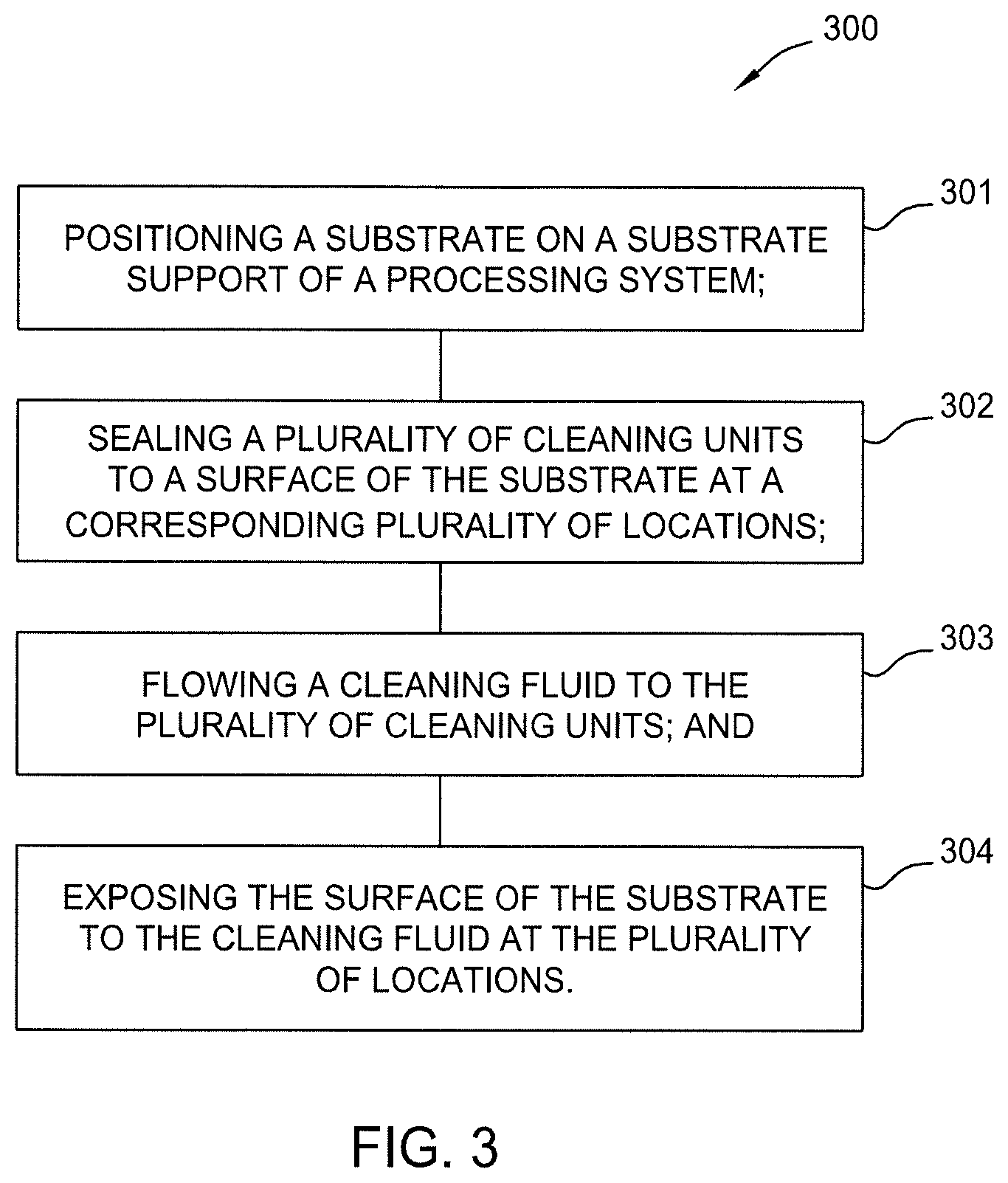
[0037] FIG. 3 is a flow diagram setting forth a method of cleaning adhesive residue from a plurality of locations on a surface of a substrate, such as the lithography mask 101 described in FIGS. 1A-1B. At activity 301 the method 300 includes positioning the substrate on a substrate support of a processing system, such as the processing system 200 described in FIGS. 2A-2C.
[0038] At activity 302 the method 300 includes sealing the ends of a plurality of cleaning units to a surface of the substrate at a corresponding plurality of locations. Here, sealing the ends of the plurality of cleaning units to the surface of the substrate comprises one or both of raising the substrate support or lowering a fluid distribution assembly until a plurality of gaskets disposed on the cleaning units sealingly contact the surface of the substrate.
[0039] At activity 303 the method 300 includes flowing a cleaning fluid through the plurality of cleaning units. In some embodiments, the cleaning fluid comprises an organic solvent. For example, in some embodiments, the cleaning fluid comprises one or a combination of dimethyl sulfoxide; 1-phenoxypropan-2-ol; 1-methyl-2-pyrrolidinonem; 2-phenoxyethanolm; 4-nonylphenol, branched, ethoxylated; dichloromethane; dimethylformamide; dichloromethane; methanol; or hydrotreated light distillate (hydrotreated petroleum distillate). In some embodiments, the cleaning fluid comprises one or a combination of the compositions A-D set forth in Table 1.
TABLE-US-00001 TABLE 1 Composition Chemical vol. % A dimethyl sulfoxide 75-95 1-phenoxypropan-2-ol 5-25 B 1-methyl-2-pyrrolidinone 75-95 2-phenoxyethanol 5-20 C 4-nonylphenol, branched, ethoxylated 0.5-2 dichloromethane 5-95 dimethylformamide 5-95 D dichloromethane 60-90 methanol 5-20 hydrotreated light distillate 0.5-5
[0040] At activity 304 the method 300 includes exposing the surface of the substrate to the cleaning fluid at the plurality of locations. In some embodiments, the method 300 further includes heating the cleaning fluid to between about 50.degree. C. and about 160.degree. C., such as between about 50.degree. C. and about 150.degree. C., or between about 90.degree. C. and about 150.degree. C. In some embodiments, the method 300 further includes recirculating the cleaning fluid to a cleaning fluid source container. In some embodiments, the method 300 further includes flowing a rinsing fluid to the plurality of cleaning units and exposing the surface of the substrate to the rinsing agent at the plurality of locations. In some embodiments, the method 300 further includes flowing a drying gas to the plurality of cleaning units and exposing the surface of the substrate to the drying gas at the plurality of locations.
[0041] Typically, the gasket will have some residual cleaning fluid disposed thereon which may undesirably drip onto the substrate when the cleaning units are separated therefrom. Therefore, to prevent dripping, in some embodiments, the method 300 further includes maintaining a vacuum on the cleaning units while separating the cleaning units from the surface of the substrate.
[0042] The methods and processing systems described herein beneficially provide for the delivery of a solvent to selective locations on the surface of a EUV lithography mask to facilitate the removal of pellicle adhesive residue therefrom. Further, because solvents used herein can cause undesirable damage to the absorber layer of an EUV lithography mask, delivering the solvent to selective locations facilitates removal of the pellicle adhesive from the lithography mask using relatively aggressive solvents without causing undesirable damage to the fragile patterned surfaces disposed thereon.
[0043] While the foregoing is directed to embodiments of the present disclosure, other and further embodiments of the disclosure may be devised without departing from the basic scope thereof, and the scope thereof is determined by the claims that follow.
* * * * *
D00000
D00001
D00002
D00003
D00004
D00005
XML
uspto.report is an independent third-party trademark research tool that is not affiliated, endorsed, or sponsored by the United States Patent and Trademark Office (USPTO) or any other governmental organization. The information provided by uspto.report is based on publicly available data at the time of writing and is intended for informational purposes only.
While we strive to provide accurate and up-to-date information, we do not guarantee the accuracy, completeness, reliability, or suitability of the information displayed on this site. The use of this site is at your own risk. Any reliance you place on such information is therefore strictly at your own risk.
All official trademark data, including owner information, should be verified by visiting the official USPTO website at www.uspto.gov. This site is not intended to replace professional legal advice and should not be used as a substitute for consulting with a legal professional who is knowledgeable about trademark law.