Steerable Endoscope With Continuum Manipulator
Garbin; Nicolo ; et al.
U.S. patent application number 16/465621 was filed with the patent office on 2020-01-16 for steerable endoscope with continuum manipulator. The applicant listed for this patent is Vanderbilt University. Invention is credited to Nicolo Garbin, Keith L. Obstein, Nabil Simaan, Piotr Robert Slawinski, Pietro Valdastri.
| Application Number | 20200015657 16/465621 |
| Document ID | / |
| Family ID | 62242774 |
| Filed Date | 2020-01-16 |


| United States Patent Application | 20200015657 |
| Kind Code | A1 |
| Garbin; Nicolo ; et al. | January 16, 2020 |
STEERABLE ENDOSCOPE WITH CONTINUUM MANIPULATOR
Abstract
A steerable endoscope system includes a continuum manipulator, a plurality of syringes, and a steerable tip. The continuum manipulator includes a plurality of spaced discs and a plurality of backbones each extending through all discs. A bending movement of the continuum manipulator changes a varying linear displacement of each backbone. Each backbone is further coupled to a different one of the syringes such that the linear displacement of each backbone pushes or pulls a piston of the corresponding syringe by a varying amount. The steerable tip includes a plurality of bellows each pneumatically coupled to a different syringe such that movement of the piston of a syringe causes the corresponding bellow to inflate or deflate. Because the distal end of each bellow is fixedly coupled to the same end effector, variations in the amount of inflation or deflation on each bellow causes a bending of the steerable tip.
| Inventors: | Garbin; Nicolo; (Nashville, TN) ; Valdastri; Pietro; (Leeds, GB) ; Obstein; Keith L.; (Nashville, TN) ; Simaan; Nabil; (Nashville, TN) ; Slawinski; Piotr Robert; (Lincoln, NE) | ||||||||||
| Applicant: |
|
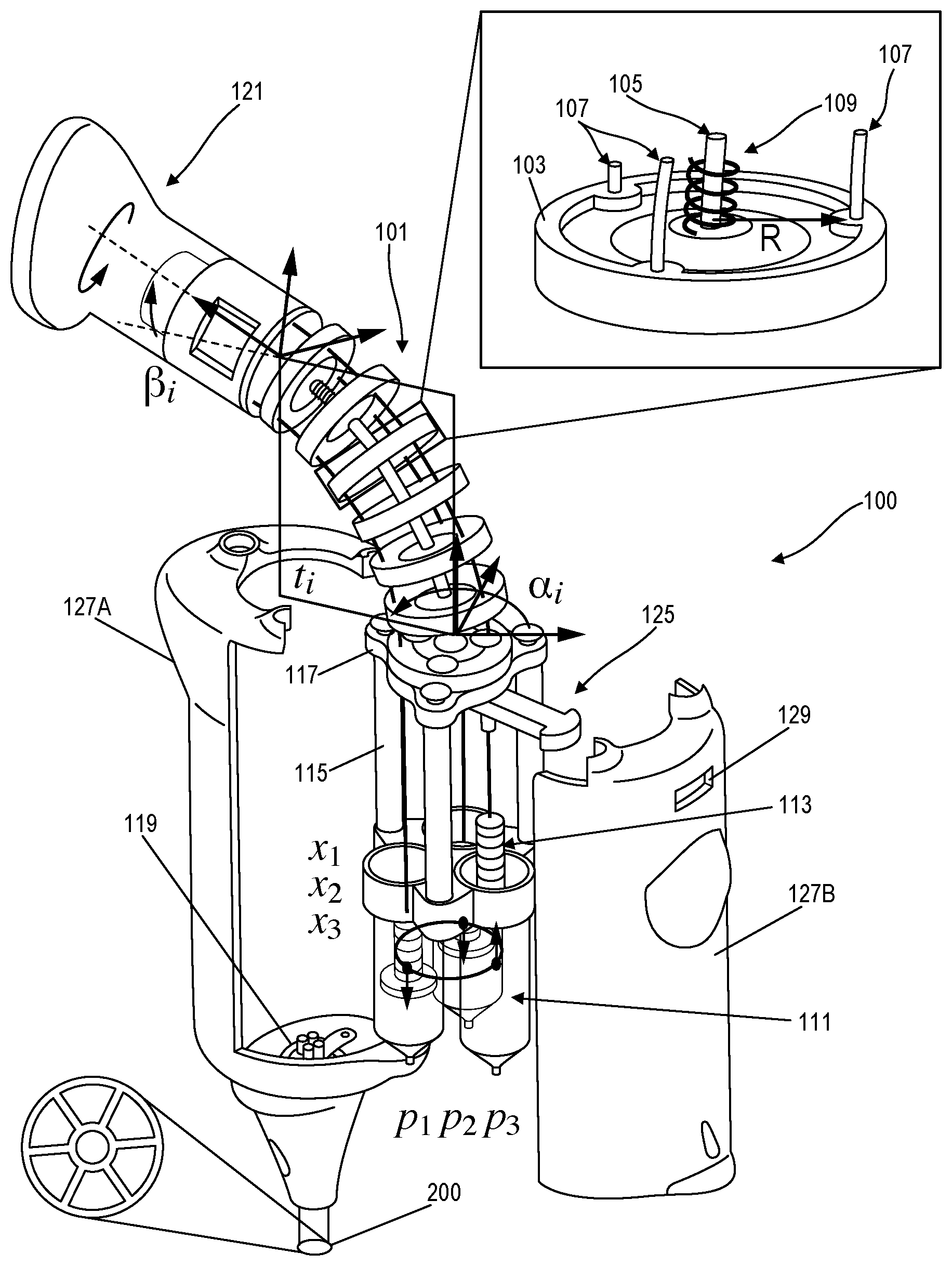
||||||||||
|---|---|---|---|---|---|---|---|---|---|---|---|
| Family ID: | 62242774 | ||||||||||
| Appl. No.: | 16/465621 | ||||||||||
| Filed: | December 1, 2017 | ||||||||||
| PCT Filed: | December 1, 2017 | ||||||||||
| PCT NO: | PCT/US2017/064271 | ||||||||||
| 371 Date: | May 31, 2019 |
Related U.S. Patent Documents
| Application Number | Filing Date | Patent Number | ||
|---|---|---|---|---|
| 62429675 | Dec 2, 2016 | |||
| 62507110 | May 16, 2017 | |||
| Current U.S. Class: | 1/1 |
| Current CPC Class: | A61B 1/12 20130101; A61M 2025/0085 20130101; A61B 1/2733 20130101; A61M 25/0155 20130101; A61B 1/0055 20130101; A61B 1/0057 20130101; A61M 25/0084 20130101; A61B 2017/00323 20130101; A61B 1/0052 20130101; A61M 25/0138 20130101 |
| International Class: | A61B 1/005 20060101 A61B001/005; A61M 25/01 20060101 A61M025/01; A61M 25/00 20060101 A61M025/00; A61B 1/273 20060101 A61B001/273 |
Goverment Interests
STATEMENT REGARDING FEDERALLY SPONSORED RESEARCH OR DEVELOPMENT
[0002] This invention was made with government support under 4224513461 awarded by the National Science Foundation. The government has certain rights in the invention.
Claims
1. A steerable endoscope system comprising: an continuum manipulator including a plurality of spaced discs each including a plurality of backbone openings, and a plurality of backbones each including a proximal end fixedly coupled to a proximal end of the continuum manipulator and a distal end extending from a distal end of the continuum manipulator, wherein each backbone of the plurality of backbones slidably extends through a backbone opening of each disc of the plurality of spaced discs, wherein the continuum manipulator is configured such that a bending movement of the continuum manipulator changes a linear displacement of the distal end of each backbone of the plurality of backbones extending from the distal end of the continuum manipulator; a plurality of syringes coupled to the continuum manipulator, wherein each syringe of the plurality of syringes is coupled to the distal end of a different one of the plurality of backbones such that linear displacement of a backbone in a first direction pushes a piston of the syringe and linear displacement of the backbone in a second direction pulls the piston of the syringe; and a steerable tip including an end effector and a plurality of bellows, wherein each bellow of the plurality of bellows is pneumatically coupled to a different syringe of the plurality of syringes such that movement of the piston of a syringe in the first direction causes inflation of a bellow of the plurality of bellows and movement of the piston of the syringe in the second direction causes deflation of the bellow, wherein a distal end of each bellow of the plurality of bellows is fixedly coupled to the end effector such that inflation variations in the plurality of bellows causes a bending of the steerable tip.
2. The steerable endoscope system of claim 1, further comprising: an actuator including the continuum manipulator and the plurality of syringes; and a catheter, wherein the catheter includes a plurality of internal pressure-medium channels, wherein the actuator is coupled to the distal tip by the catheter, and wherein the plurality of syringes is coupled to the plurality of bellows by the plurality of internal pressure-medium channels of the catheter.
3. The steerable endoscope system of claim 2, wherein the pressure-medium channels include pneumatic channels and wherein each syringe is pneumatically coupled to a corresponding bellow.
4. The steerable endoscope of claim 2, wherein the pressure-medium channels include fluid-pressure channels and wherein each syringe is configured to inflate or deflate a corresponding bellow by applying a fluid pressure to the bellow through a fluid-pressure channel.
5. The steerable endoscope system of claim 1, wherein the catheter further includes an instrument channel extending from the actuator to the steerable tip.
6. The steerable endoscope system of claim 1, further comprising a handle coupled to a proximal end of the continuum manipulator by a bearing configured to allow rotation of the handle about a linear axis of the continuum manipulator.
7. The steerable endoscope system of claim 1, wherein the continuum manipulator further includes a primary backbone extending through each disc of the plurality of spaced discs, wherein the plurality of backbones includes a plurality of secondary backbones, and wherein the plurality of backbone openings of each disc of the plurality of spaced discs includes a primary backbone opening positioned at a center of the disc and a plurality of secondary backbone openings positioned around the primary backbone opening at a defined radius from the primary backbone opening.
8. The steerable endoscope system of claim 7, further comprising a handle coupled to the continuum manipulator at the proximal end of the continuum manipulator, wherein a proximal end of the primary backbone is fixedly coupled to the proximal end of the continuum manipulator, wherein a distal end of the primary backbone extends from the distal end of the continuum manipulator, and wherein the continuum manipulator is configured such that an external linear force applied to the handle in the second direction increases a stiffness of the steerable tip by causing all bellows of the plurality of bellows to deflate.
9. The steerable endoscope of claim 8, further comprising a slidable lock positioned near the distal end of the continuum manipulator and slidable in a direction perpendicular to the distal end of the primary backbone extending from the distal end of the continuum manipulator, wherein the slidable lock is configured such that sliding the slidable lock in a direct towards the primary backbone causes the slidable lock to frictionally engage the primary backbone and restrict linear movement of the primary backbone.
10. The steerable endoscope system of claim 7, wherein the continuum manipulator further includes a helical spring positioned coaxially around the primary backbone, wherein the helical spring maintains a spacing between at least two discs of the plurality of spaced discs.
11. The steerable endoscope system of claim 1, wherein the bending of the steerable tip is proportionally scaled relative to the bending movement of the continuum manipulator.
12. The steerable endoscope system of claim 11, wherein the plurality of syringes includes a first plurality of syringes, wherein each syringe of the first plurality of syringes has a first piston stroke length and a first volume.
13. The steerable endoscope of claim 12, further comprising a second plurality of syringes, wherein each syringe of the second plurality of syringes has a second piston stroke length and a second volume, wherein the second plurality of syringes are selectively interchangeable with the first plurality of syringes, and wherein interchanging the second plurality of syringes for the first plurality of syringes alters a proportional scalability of the bending of the steerable tip relative to the bending movement of the continuum manipulator.
14. A method of operating the steerable endoscope of claim 1, comprising bending the steerable tip by applying a bending force to the continuum manipulator.
15. The method of claim 14, further comprising changing a bending angle of the steerable tip by changing an angle of the bending force applied to the continuum manipulator.
16. The method of claim 14, further comprising increasing a magnitude of bending of the steerable tip by adjusting the bending force applied to the continuum manipulator to increase a magnitude of the bending of the continuum manipulator.
17. The method of claim 14, further comprising increasing a stiffness of the steerable tip by applying a pulling force to the proximal end of the continuum manipulator which causes all bellows of the plurality of bellows to deflate.
18. A steerable endoscope system comprising: an actuator including a continuum manipulator including a plurality of spaced discs each with a primary backbone opening positioned at the center of the disc and a plurality of secondary backbone openings each positioned around the primary backbone opening at a defined lateral distance from the primary backbone opening, a primary backbone with a proximal end fixedly coupled relative to a proximal end of the continuum manipulator and a distal end extending from a distal end of the continuum manipulator, wherein the primary backbone extends through the primary backbone opening of each disc of the plurality of spaced discs, and a first secondary backbone with a proximal end fixedly coupled relative to the proximal end of the continuum manipulator and a distal end extending from the distal end of the continuum manipulator, wherein the first secondary backbone extends through a first secondary backbone opening of the plurality of secondary backbone openings of each disc of the plurality of spaced discs, wherein a bending movement applied to the continuum manipulator by a user changes a linear displacement of the distal end of the first secondary backbone extending from the distal end of the continuum manipulator, and a first syringe coupled to the distal end of the first secondary backbone such that linear movement of the distal end of the first secondary backbone in a first direction pushes a piston of the first syringe and linear movement of the distal end of the first secondary backbone in a second direction pulls the piston of the first syringe: a catheter coupled to the actuator at a proximal end of the catheter and including a first pneumatic channel coupled to an outlet of the first syringe; and a steerable tip coupled to a distal end of the catheter, the steerable tip including a first bellow pneumatically coupled to the first syringe by the first pneumatic channel of the catheter such that pushing the piston of the first syringe causes an inflation of the first bellow and pulling the piston of the first syringe causes a deflation of the first bellow, wherein the inflation and the deflation of the first bellow influences a bending movement of the steerable tip.
19. The steerable endoscope system of claim 18, wherein the continuum manipulator further includes a second secondary backbone with a proximal end fixedly coupled relative to the proximal end of the continuum manipulator and a distal end extending from the distal end of the continuum manipulator, wherein the second secondary backbone extends through a second secondary backbone opening of the plurality of backbone openings of each disc of the plurality of spaced discs, wherein the bending movement applied to the continuum manipulator by the user changes a linear displacement of the distal end of the second secondary backbone, wherein the actuator further includes a second syringe coupled to the distal end of the second secondary backbone such that linear movement of the distal end of the second secondary backbone in the first direction pushes a piston of the second syringe and linear movement of the distal end of the second secondary backbone in the second direction pulls the piston of the second syringe, wherein the catheter further includes a second pneumatic channel coupled to an outlet of the second syringe, and wherein the steerable tip includes a second bellow pneumatically coupled to the second syringe by the second pneumatic channel of the catheter such that pushing the piston of the second syringe causes an inflation of the second bellow and pulling the piston of the second syringe causes a deflation of the second bellow, and wherein variations between the inflation and the deflation of the second bellow relative to the inflation and the deflation of the first bellow causes the bending movement of the steerable tip.
20. The steerable endoscope system of claim 19, wherein the continuum manipulator further includes a third secondary backbone with a proximal end fixedly coupled relative to the proximal end of the continuum manipulator and a distal end extending from the distal end of the continuum manipulator, wherein the third secondary backbone extends through a third secondary backbone opening of the plurality of backbone openings of each disc of the plurality of spaced discs, wherein the bending movement applied to the continuum manipulator by the user changes a linear displacement of the distal end of the third secondary backbone, wherein the actuator further includes a third syringe coupled to the distal end of the third secondary backbone such that linear movement of the distal end of the third secondary backbone in the first direction pushes a piston of the third syringe and linear movement of the distal end of the third secondary backbone in the third direction pulls the piston of the second syringe, wherein the catheter further includes a third pneumatic channel coupled to an outlet of the third syringe, and wherein the steerable tip includes a third bellow pneumatically coupled to the third syringe by the third pneumatic channel of the catheter such that pushing the piston of the third syringe causes an inflation of the third bellow and pulling the piston of the third syringe causes a deflation of the third bellow, and wherein variations between the inflation and the deflation of the third bellow relative to the inflation and the deflation of the first bellow and relative to the inflation and the deflation of the second bellow causes the bending movement of the steerable tip.
Description
RELATED APPLICATIONS
[0001] This application claims the benefit of U.S. Provisional Patent Application No. 62/429,675, filed Dec. 2, 2016, entitled "DISPOSABLE ENDOSCOPE," and U.S. Provisional Patent Application No. 62/507,110, filed May 16, 2017, entitled "DISPOSABLE ENDOSCOPE." the entire contents of both of which are incorporated herein by reference.
BACKGROUND
[0003] The present invention relates to a steerable endoscope and, in particular, systems and methods for adjusting a bending angle of an end-effector of an endoscope.
SUMMARY
[0004] Upper endoscopy or Esophagogastroduodenoscopy (EGD) is currently performed in an endoscopic unit, emergency department, or intensive care unit due to the equipment utilized and the administration of sedation with need for patient monitoring. This limits broad primary patient access and exposes patients to sedation-related adverse events. If sedation can be avoided, bedside clinic-based EGD can be enabled for a host of applications (e.g., esophageal varices screening, gastroesophageal reflux disease non-responsive to medical therapy, suspected upper gastrointestinal (GI) tract bleeding, and dysphagia). In addition, traditional endoscopes require reprocessing between each use, thereby increasing cost of care, and effective operation of an endoscope requires long training due to a non-intuitive maneuvering/control mechanism.
[0005] To overcome these and other challenges, various embodiments of the invention provide an endoscope system with intrinsic pneumatic actuation. The endoscope system includes a user interface (e.g., an "actuator" or a "controller") using a continuum manipulator architecture and a steerable tip using parallel bellow actuators. Operation of this endoscope is intuitive in that bending movement of the steerable tip is controlled by a corresponding bending movement applied by the user to the user interface. In some implementations, three super-elastic NiTi backbones within the user interface are connected to the user's handle. The free ends of these backbones provide push-and-pull action for moving three corresponding syringe pistons. The pistons, in turn, displace air-filled tubes to expand/contract three corresponding parallel bellows in the steerable tip.
[0006] In one embodiment, the invention provides a steerable endoscope system including a continuum manipulator, a plurality of syringes, and a steerable tip. The continuum manipulator includes a plurality of spaced discs and a plurality of backbones each extending through all discs of the plurality of spaced discs. The continuum manipulator is configured such that a bending movement of the continuum manipulator changes a varying linear displacement of each backbone. Each backbone is further coupled to a different one of the plurality of syringes such that the linear displacement of each backbone pushes or pulls a piston of the corresponding syringe by a varying amount. The steerable tip includes a plurality of bellows each pneumatically coupled to a different syringe such that movement of the piston of a syringe causes the corresponding bellow to inflate or deflate by varying amounts. Because the distal end of each bellow is fixedly coupled to the same end effector, variations in the amount of inflation or deflation on each bellow causes a bending of the steerable tip.
[0007] Other aspects of the invention will become apparent by consideration of the detailed description and accompanying drawings.
BRIEF DESCRIPTION OF THE DRAWINGS
[0008] FIG. 1 is an exploded perspective view of an actuator for an endoscope according to one embodiment.
[0009] FIG. 2 is a cross-sectional view of an endoscope catheter for use with the actuator of FIG. 1.
[0010] FIG. 3 is an exploded perspective view of a steerable tip of an endoscope controlled by the actuator of FIG. 1.
[0011] FIG. 4 is a perspective view of another example of a steerable tip of an endoscope controllable by the actuator of FIG. 1.
[0012] FIG. 5 is a schematic flowchart of a method for controlling the steerable tip of FIG. 3 using the actuator of FIG. 1.
[0013] FIGS. 6A, 6B. 6C, and 6D are overhead views of the steerable tip of FIG. 3 and the actuator of FIG. 1 showing various positions of the actuator and a corresponding position of the steerable tip.
[0014] FIGS. 7A and 7B are perspective views of the steerable tip of FIG. 3 in two different modes of operation including a mode of operation where the stiffness of the tip is increased to limit movement of the steerable tip.
DETAILED DESCRIPTION
[0015] Before any embodiments of the invention are explained in detail, it is to be understood that the invention is not limited in its application to the details of construction and the arrangement of components set forth in the following description or illustrated in the following drawings. The invention is capable of other embodiments and of being practiced or of being carried out in various ways.
[0016] FIG. 1 illustrates an actuator 100 (or "controller") for an endoscope. By manipulating the actuator 100, a user is able to control a steerable tip of the endoscope that is coupled to the actuator 100 by a catheter, as described in further detail below. The actuator 100 includes a continuum manipulator 101. The continuum manipulator 101 includes a plurality of disks 103 arranged along a primary backbone 105. As shown in the insert of FIG. 1, a series of three secondary backbones 107 are arranged along a pitch circle with a radius R. Accordingly, each secondary backbone passes through an opening in each disc 103 at the same distance, R, from the opening through which the primary backbone 105 passes. A spring 109 is positioned coaxially around the primary backbone 105 as a spacer between the discs 103.
[0017] Each secondary backbone 107 is configured to slidably move through the opening of each disc 103 as described further below. In the example of FIG. 1, the primary backbone 105 is also configured to slidably move relative to each disc 103 through a center opening. However, the spring 109 maintains a spacing between the discs 103. Accordingly, when the continuum manipulator 101 is bent (for example, as shown in FIG. 1), the secondary backbones 107 will slidably move relative to the discs 103 causing one or more of the secondary backbones 107 to extend or retract relative to the distal end of the continuum manipulator 101. Such bending movements (or other movements such as, for example, linear pushing or pulling on the continuum manipulator 101) may also cause the primary backbone 105 to extend of retract relative to the distal end of the continuum manipulator 101. However, the springs 109 act on the discs 103 applying a force that urges the spacing between neighboring discs 103 to return to a relatively constant equilibrium spacing distance.
[0018] In some implementations, a single spring 109 runs the entire length of the continuum manipulator 101 with each disc 103 coupled to a particular location on the spring 109 due to the helical shape of the spring. In other implementations, separate individual springs 109 may be positioned between each set of neighboring discs 103. In still other implementations, the spring 109 may be omitted entirely and, instead, a fixed spacing distance between each disc 103 is maintained by fixedly coupling the primary backbone 105 to each disc 103 at locations along the length of the primary backbone 105. In other implementations, one or more additional springs may be positioned coaxial to each of the secondary backbones 107 such that the spring force of each additional spring counteracts a bending force applied to the continuum manipulator 101 and urging the continuum manipulator 101 to return to an equilibrium pose (e.g., where each of the backbones is straight).
[0019] Returning now to the example of FIG. 1, a distal end of each of the three secondary backbones 107 is coupled to a different one of three syringes 111. In this disclosure, the term "syringe" is used to refer to devices where a linear movement causes an increase or decrease in air or fluid pressure including, for example, a device where a piston is positioned within a cylinder and movement of the piston within the cylinder causes a change in an enclosed volume of the cylinder. In the example of FIG. 1, each secondary backbone 107 is coupled to a piston of the respective syringe 111 by a screw connector 113. A series of three spacing pillars 115 couple the syringes 111 to a base 117 at the distal end of the continuum manipulator 101. Accordingly, the outer bodies of the syringes 111 remain at a fixed distance from the continuum manipulator 101. However, as discussed in further detail below, linear movement (x.sub.1, x.sub.2, x.sub.3) of each individual secondary backbone 107 pushes or pulls a piston of the corresponding syringe 111 relative to the outer body of the syringe 111. This displacement of the piston (caused by movement of the corresponding secondary backbone 107) generates a change in air pressure (p.sub.1, p.sub.2, p.sub.3) for the corresponding syringe 111. Although, in the example of FIG. 1, the secondary backbones 107 are coupled to the pistons of the syringes 111 while the outer bodies of the syringes 111 are maintained at a stationary distance from the base 117 of the continuum manipulator 101, in other implementations, the secondary backbones 107 may instead be coupled to the outer bodies of the syringes 111 while the pistons of the syringes 111 are held at a stationary distance from the base 117.
[0020] The outlet of each syringe 111 is coupled to a catheter 200 by an adapter 119. As discussed in further detail below, the catheter 200 includes different lumens (or "pneumatic channel") for each syringe 111. Accordingly, movement of a piston into the corresponding outer body of a syringe 111 causes the syringe 111 to push air through the adapter 119 into the catheter 200 and, conversely, retracting the piston from the outer body of a syringe 111 cases the syringe 111 to pull air from the catheter into the syringe 111 through the adapter 119.
[0021] A handle 119 is coupled to a proximal end of the continuum manipulator 101. In the example of FIG. 1, the handle 119 is rotatably coupled to the continuum manipulator 101 by a bearing aligned with a longitudinal axis of the actuator 100. This rotatable coupling avoids mechanical lock due to possible twisting of the continuum manipulator 101. When using the actuator 100 to control the steerable tip of the endoscope, a user will hold the actuator by the handle 119 and bend the continuum manipulator relative to the base 117. This bending motion of the continuum manipulator 101 causes a change in the linear position of one or more of the secondary backbones 107 and, in turn, a change in the position of the piston of the corresponding syringe 111.
[0022] In the example of FIG. 1, a user can also pull the handle (e.g., linearly) away from the base 117 (causing the pistons in all syringes 111 to retract) or push the handle (e.g., linearly) towards the base 117 (causing the pistons in all syringes 111 to extend further). As discussed in further detail below, the pushing or pulling the handle (e.g., linearly) relative to the base 117 can be done to adjust a stiffness of the steerable tip and to provide for more controlled movements. The actuator 100 of FIG. 1 also includes a slider lock 125 positioned adjacent to (or incorporated into) the base 117. The slider lock 125 moves slidably in a linear direction perpendicular to the spacing pillars 115. When pushed toward the primary backbone 105 (extending from the distal end of the continuum manipulator 101 near the base 117), the slider lock 125 engages the primary backbone 105 by friction and prevents (or, in some implementations, restricts) linear movement of the primary backbone 105. Sliding the slider lock 125 away from the primary backbone 105 releases the primary backbone 105 restoring its ability for linear movement. In this way, when the "stiffness" of the continuum manipulator 101 and the steerable tip of the endoscope is adjusted by a user pushing or pulling the handle 121, the slider lock 125 can be slid into place to engage the primary backbone 105 and, thereby, maintain the desired level of stiffness. Accordingly, the continuum manipulator 101 of FIG. 1 can be moved with three degrees-of-freedom (DoF): two bending angles (.alpha..sub.i and .beta..sub.i) and elongation (l.sub.i).
[0023] The actuator 100 illustrated in FIG. 1 also includes an external housing 127 formed, in this example, as a pair of molded plastic housing sections 127A, 127B which are configured to engage by snap fit (or, in some implementations, by securing screws) to housing at least a portion of the actuator 100. In the example of FIG. 1, the external housing 127 encloses the syringes 111, the spacing pillars 115, and the base 117 of the continuum manipulator 101. The continuum manipulator 101 (and the handle 121) extends from an opening at the top of the housing 127 and the adapter 119 extends from an opening at the bottom of the housing 127. The slider lock 125 extends through an opening 129 in a side of the housing 127B.
[0024] In the example of FIG. 1, the primary backbone 105 is formed of 1.5 mm NiTi wire and the secondary backbones 107 are formed of 1.0 mm NiTi wire. The spring 109 is rated at 3.65 lbs/in and has a compressed length of up to 48% of its initial length. Each spacer disc 103 is 5.5 mm thick. The pitch radius (i.e., the distance between the primary backbone 105 and each secondary backbone 107 along each disc 103) is 12.5 mm. In other implementations, different material (with different sizes and/or ratings) may be used. However, in this example using these materials, a maximal bending angle B.sub.i-max of -24.64 can be calculated using the equation:
x.sub.j=.+-.R(.beta..sub.i-rest-.beta..sub.i-max); j=1, 2, 3 (1)
where x.sub.j=.+-.25 mm, pitch radius R=12.5 mm, and .beta..sub.i-rest=.pi./2. Considering compressibility of the spring along the primary backbone 105, the length of the continuum manipulator 101 at rest is such that, when the springs are fully compressed, it reaches a positive 25 mm displacement.
[0025] As discussed above, the actuator 100 couples to a catheter 200 at the adapter 119. In some implementations, the adapter 119 is configured to permanently couple the actuator 100 to a catheter 200 (for example, by a threaded screw fitting) to allow the catheter to be replaced or exchanged for different uses and applications. FIG. 2 illustrates an example of a catheter 200 configured for use with the actuator 100. The catheter 200 may be formed of a material such as, for example, NuSil MED-4880 silicone. As shown in cross-section in the example of FIG. 2, the catheter 200 includes seven different lumens (or "channels"). A central lumen (labeled as w in FIG. 2) embeds a wire rope in the catheter 200 to increase axial stiffness of the catheter 200. Three of the lumens (labelled as p.sub.1, p.sub.2, and p.sub.3 in FIG. 2) are pneumatic channels each extending between a different one of the syringes 111 of the actuator 100 and a corresponding bellow of the steerable tip (discussed further below).
[0026] The video lumen (labelled v in FIG. 2) is used for electrical and data wiring to a camera positioned at the tip of the endoscope. A fluid channel (labelled lc in FIG. 2) is used to run water for cleaning a lens of the camera at the tip of the endoscope while in use. The last channel (labelled i in FIG. 2) is an insufflation channel with an opening at the base of the steerable tip. It is again noted that the catheter 200 of FIG. 2 is just one example of a catheter for use with the actuator 100 of FIG. 1. In other implementations, the catheter 200 may be configured to include more, fewer, or different lumens or different shapes, sizes, and configurations. Furthermore, in the example of FIG. 1, the actuator 100 does not show opening or other structures for coupling to the proximal end of the video lumen v, the fluid lumen lc, or the insufflation lumen i. However, in some implementations, couplings for the proximal end of these (or other) channels may be provided, for example, by the adapter 119 extending from the bottom of the housing 127 of the actuator 100 or may be incorporated into the actuator 100 itself.
[0027] FIG. 3 illustrates an example of a steerable tip 300 positioned at a distal end of the endoscope and coupled (or couplable) to the actuator 100 by the catheter 200. In this example, the steerable tip 300 includes a series of three bellow 301. In this example, the bellows 301 are constructed of a rubber material and each has a nominal diameter of 5.6 mm, a maximal length of 29 mm, and a minimal length of 14 mm. The bellows 301 are arranged as the vertices of an equilateral triangle. Each individual bellow 301 is pneumatically coupled to a different corresponding syringe 111 by a pneumatic channel of the catheter 200. A tip adapter 303 pneumatically couples each individual bellow 301 to a different pneumatic channel of the catheter 200.
[0028] The steerable tip 300 also includes a tip housing 305 positioned at a distal end of the bellows 301. In the example of FIG. 3, the tip housing 305 is again formed as a pair of molded plastic housing components that snap-fit to enclose the components at the distal tip. In particular, a camera 307 is positioned at the distal tip and enclosed by the tip housing 305. In this example, the camera includes a 720.times.576 pixel camera (RA78080A-60LED Bangu Technology Development Co., Baoan, China). The tip housing 305 also holds and positions a lens 309 (e.g., a sapphire lens) for the camera 307 in the field of view of the camera 307 which, among other things, provides waterproofing for the camera 307. A cleaning nozzle 311 extends from the tip housing 305 and is positioned and configured to dispense water on the lens 309 to clean the lens 309 during use. The tip adapter 303 also provides for coupling wires for the camera 307 and fluid channels for the cleaning nozzle 311 to the respective lumen of the catheter 200.
[0029] FIG. 4 illustrates another, simplified example of a distal tip for use with the actuator 100 of FIG. 1. This example shows only the three bellows 401A, 401B, 401C coupled between a catheter 403 and an end effector 405. When a piston of a syringe 111 moves, it creates air pressure that pushes or pulls air through the pneumatic channel of the catheter into an individual bellow (e.g., 401A, 401B, or 401C). This causes that particular bellow to extend or retract accordingly. The comparative extension and retraction of each of the three bellows 401A, 401B, 401C causes the end effector 405 to bend (as shown in FIG. 4). The steerable tip 300 of FIG. 3 operates in this same way. Because the bellows can be independently extended/contracted using the pneumatic pressures p.sub.1, p.sub.2, p.sub.3, the movement of the steerable tip 300 can be controlled with three degrees-of-freedom (DoF): two tilting angles (.alpha..sub.0 and .beta..sub.0 illustrated in FIG. 3) and an elongation (l.sub.0 in FIG. 3).
[0030] FIG. 5 provides a schematic illustration of how the bending of the continuum manipulator 101, the secondary backbones 107A, 107B, 107C, the pistons of the syringes 111A. 111B, 11C, and the bellows 301A, 301B, 301C interact to provide for controlled bending (or "steering") of the steerable tip 300. As discussed above, bending of the continuum manipulator 101 by a user causes a change in the linear position x.sub.1, x.sub.2, x.sub.3 of one or more secondary backbone 107A, 107B, 107C. Due to the fixed coupled of the distal end of each secondary backbone 107A, 107B, 107C to a corresponding syringe 111A, 111B, 111C, the changes in the linear position x.sub.1, x.sub.2, x.sub.3 of each secondary backbone 107A, 107B, 107C acts on the corresponding syringe 111A, 111B, 111C and, thereby, causes a corresponding change in the air pressure p.sub.1, p.sub.2, p.sub.3 of each syringe 111A, 111B, 111C. This type of change in pressure in any one of the syringes 111A, 111B, 111C pumps air into or out of the corresponding bellow 301A, 301B, 301C through the corresponding pneumatic channel of the catheter 200.
[0031] Because each syringe is coupled to a different one of the bellows (forming three separate pneumatic systems), different changes in the linear position of the secondary backbones 107A, 107B. 107C results in different magnitudes of inflation or deflation in the corresponding bellows 301A, 301B, 301C. Because all three of the bellow 301A, 301B, 301C are fixedly coupled between the tip adapter 303 and the tip housing 305, variations in the magnitude of inflation or deflation causes the steerable tip 300 to bend at the bellows 301A, 301B, 301C.
[0032] For example, as the handle 121 is moved to bend the continuum manipulator 101 from a straight position into the bent position illustrated in FIG. 1. The two secondary backbones 107 towards the left of the image in FIG. 1 are pushed further into their corresponding syringes 111 and the secondary backbone 107 towards the right side of the image is pulled away from its corresponding syringe 111. Returning to FIG. 5, consider a similar bending motion of the continuum manipulator 101 which cause backbone 107A and backbone 107B to extend further into syringe 111A and syringe 111B, respectively, while also causing backbone 107C to retract away from the syringe 111C. This particular set of changes in linear position of the secondary backbones 107A, 107B, 107C causes syringe 111A to push air into bellow 301A, causes syringe 111B to push air into bellow 301B, and causes syringe 111C to pull air out of bellow 301C. As a result, bellows 301A and 301B are further inflated while bellow 301C is further deflated. This particular set of inflations and deflations of the bellows 301A, 301B, and 301C causes the steerable tip 300 to bend as shown in the example of FIG. 3.
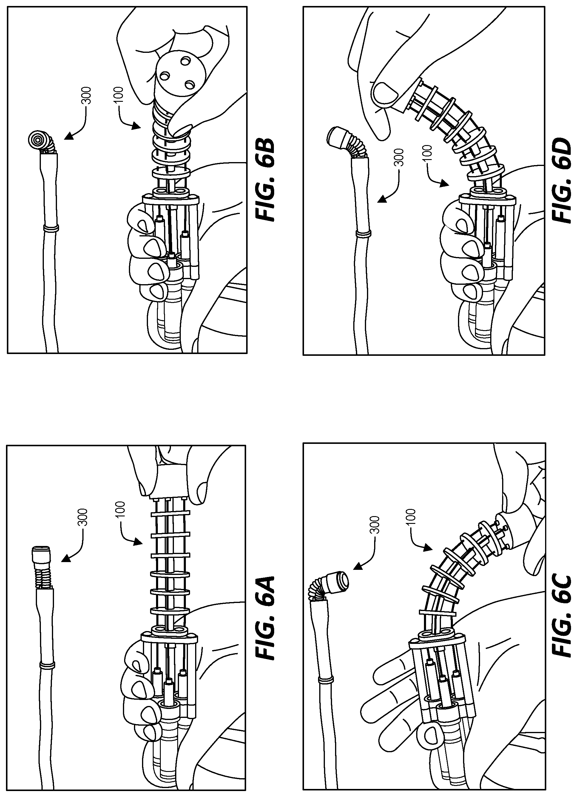
[0033] Accordingly, in the system illustrated in FIGS. 1, 2, and 3, a bending movement applied by a user to the continuum manipulator 101 of the actuator 100 causes a corresponding bending movement of the steerable tip 300. FIGS. 6A, 6B, 6C, and 6D illustrate further examples of bending movement applied by a user to the actuator 100 and the resulting corresponding bending movement exhibited by the steerable tip 300. In FIG. 6A, the actuator 100 is held straight. As a result, the bellows of the steerable tip 300 are equally inflated and the steerable tip does not bend in any direction. In the example of FIG. 6B, the actuator 100 is bent upward and, as a result, the bellows of the steerable tip 300 are correspondingly inflated or deflated causing the steerable tip 300 to also bend upwards. In the example of FIG. 6C, the actuator 100 is bent backwards and, as a result, the corresponding inflation/deflation of the bellows cause the steerable tip 300 to also bend backwards. Finally, in the example of FIG. 6D, the actuator 100 is bent forwards and, as a result, the corresponding inflation/deflation of the bellows cause the steerable tip 300 to also bend forward.
[0034] The corresponding bending movements of the steerable tip 300 and the continuum manipulator 101 of the actuator 100 exhibits an intrinsic mapping. The scaling factor between input movements performed on the actuator 100 (i.e., .alpha..sub.i, .beta..sub.i, l.sub.i) and resulting movements of the steerable tip 300 (i.e., .alpha..sub.o, .beta..sub.o, l.sub.o) can be defined, for example, by the size and dimensions of the syringes 111 of the actuator 100. In some implementations, the actuator 100 is configured to allow a user to selectively change the syringes 111 to adjust the scalability. In some implementations configured for interchangeable syringe configurations, a set of syringes is provided with a common stroke (e.g., 53 mm) and different diameters. The actuator 100 is also configured to selectively coupled the syringes into syringe holders or brackets positioned equidistantly along the circumference of a pitch circle (e.g., with a radius of 12.5 mm) to accommodate different syringe diameters.
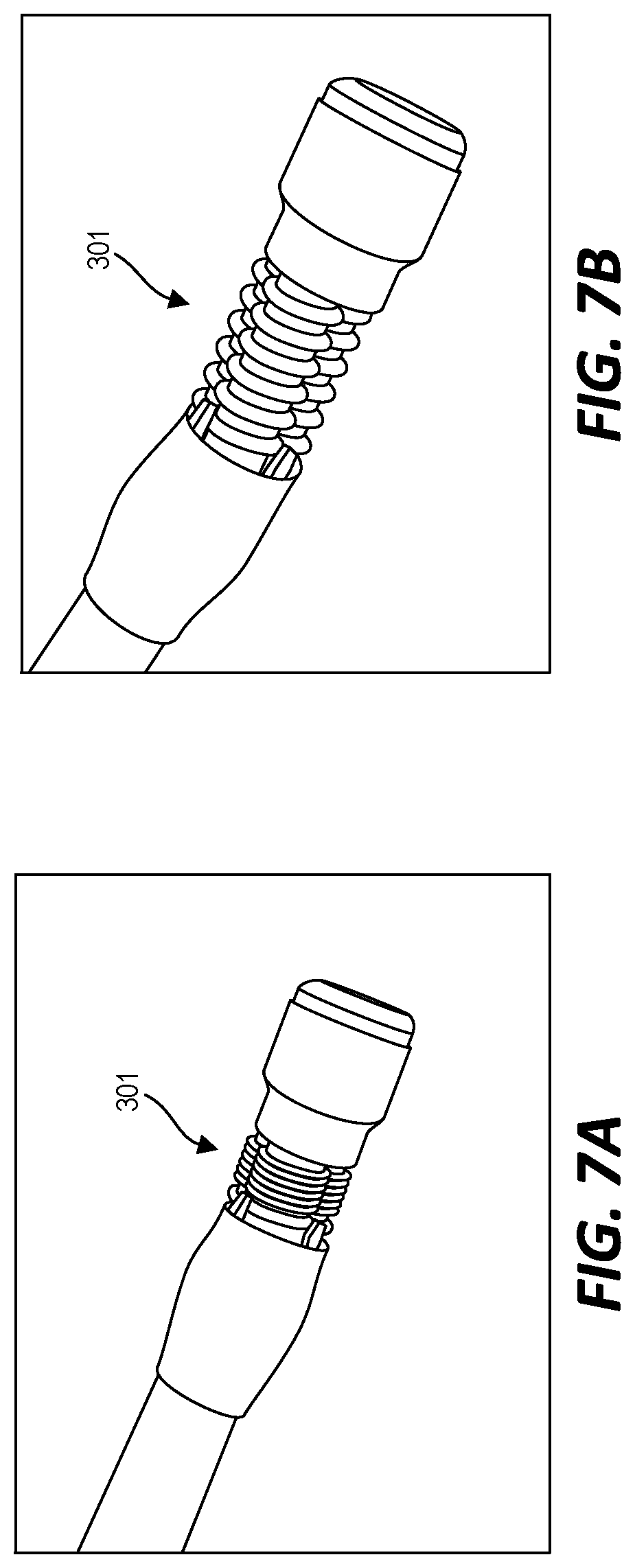
[0035] As discussed above, in the example of FIG. 1, a user can also pull or push the handle in a substantially linear direction relative to the base of the actuator 100 to cause all of the secondary backbones to move in the same direction towards or away from their corresponding syringes. FIGS. 7A and 7B illustrate that corresponding effect that this type of movement of the actuator 100 causes at the steerable tip 300. In FIG. 7A, all three of the bellows 301 are similarly deflated. This is caused by pulling the handle of the actuator 100 away from the base of the actuator 100. Conversely, FIG. 7B shows all three of the bellows 301 similarly inflated. This is caused by pushing the handle of the actuator 100 towards the base of the actuator 100 (for example, returning the handle and, in turn, the primary backbone to its original linear position after pulling the handle to cause the situation of FIG. 7A).
[0036] Pulling the handle of the actuator 100 to deflate all of the bellows 301 (as shown in FIG. 7A) increases the stiffness of the tip and can be used when inserting the endoscope tip into the upper gastrointestinal tract (UGI). This manipulation also makes the actuator 100 and, in turn, the steerable tip 300 more resistant to bending. Accordingly, a user might increase the stiffness in this way in order to make smaller adjustments to the bending position of the steerable tip 300.
[0037] Although the examples described above include a "pneumatic" system where air pressure changes via the syringe cause a corresponding bellow to inflate or deflate with air, in some implementations, the syringe and bellow are communicative coupled by a fluid medium (e.g., a "hydraulic" system). Accordingly, the pneumatic channels of the conduits discussed in reference to FIG. 2 above can be replaced in some embodiments with a fluid channel. The phrase "pressure medium channel" as used herein is understood to include a pneumatic channel or a fluid-based channel.
[0038] Thus, the invention provides, among other things, an endoscope system including an actuator and a steerable tip configured to control bending of the steerable tip by a corresponding bending of a continuum manipulator of the actuator. Various features and advantages of the invention are set forth in the following claims.
* * * * *
D00000
D00001
D00002
D00003
D00004
D00005
XML
uspto.report is an independent third-party trademark research tool that is not affiliated, endorsed, or sponsored by the United States Patent and Trademark Office (USPTO) or any other governmental organization. The information provided by uspto.report is based on publicly available data at the time of writing and is intended for informational purposes only.
While we strive to provide accurate and up-to-date information, we do not guarantee the accuracy, completeness, reliability, or suitability of the information displayed on this site. The use of this site is at your own risk. Any reliance you place on such information is therefore strictly at your own risk.
All official trademark data, including owner information, should be verified by visiting the official USPTO website at www.uspto.gov. This site is not intended to replace professional legal advice and should not be used as a substitute for consulting with a legal professional who is knowledgeable about trademark law.