Temperature-controlled Flange And Reactor System Including Same
Sreeram; Sonti ; et al.
U.S. patent application number 16/024390 was filed with the patent office on 2020-01-02 for temperature-controlled flange and reactor system including same. The applicant listed for this patent is ASM IP Holding B.V.. Invention is credited to Joe Margetis, Sonti Sreeram, Junwei Su, John Tolle.
| Application Number | 20200002811 16/024390 |
| Document ID | / |
| Family ID | 69007945 |
| Filed Date | 2020-01-02 |


View All Diagrams
| United States Patent Application | 20200002811 |
| Kind Code | A1 |
| Sreeram; Sonti ; et al. | January 2, 2020 |
TEMPERATURE-CONTROLLED FLANGE AND REACTOR SYSTEM INCLUDING SAME
Abstract
A flange, flange assembly, and reactor system including the flange and flange assembly are disclosed. An exemplary flange assembly includes heated and cooled sections to independently control temperatures of sections of the flange. Methods of using the flange, flange assembly and reactor system are also disclosed.
| Inventors: | Sreeram; Sonti; (Gilbert, AZ) ; Tolle; John; (Gilbert, AZ) ; Margetis; Joe; (Gilbert, AZ) ; Su; Junwei; (Tempe, AZ) | ||||||||||
| Applicant: |
|
||||||||||
|---|---|---|---|---|---|---|---|---|---|---|---|
| Family ID: | 69007945 | ||||||||||
| Appl. No.: | 16/024390 | ||||||||||
| Filed: | June 29, 2018 |
| Current U.S. Class: | 1/1 |
| Current CPC Class: | C23C 16/4411 20130101; C23C 16/4409 20130101; C23C 16/455 20130101 |
| International Class: | C23C 16/455 20060101 C23C016/455 |
Claims
1. A flange assembly comprising: a flange comprising: a first surface for coupling to a reactor; an opposing second surface; and an opening between the first surface and the second surface; at least one heater; and at least one cooling channel.
2. The flange assembly of claim 1, wherein the at least heater is embedded within the flange.
3. The flange assembly of claim 1, wherein the at least cooling channel is embedded within the flange.
4. The flange assembly of claim 1, wherein the first surface comprises a recess to receive a sealing member.
5. The flange assembly of claim 4, wherein the at least cooling channel is proximate the recess.
6. The flange assembly of claim 1, wherein the second surface comprises a recess to receive a sealing member.
7. The flange assembly of claim 6, wherein the at least cooling channel is proximate the recess.
8. The flange assembly of claim 1, wherein the flange further comprises an exhaust outlet.
9. The flange assembly of claim 8, wherein the at least heater is proximate the exhaust outlet.
10. The flange assembly of claim 9, wherein the flange assembly comprises at least two heaters proximate the exhaust outlet.
11. The flange assembly of claim 1, wherein the flange comprises at least two heaters on opposing sides of the opening.
12. The flange assembly of claim 1, wherein the flange comprises at least four heaters proximate the opening.
13. The flange assembly of claim 1, wherein the flange further comprises one or more openings to receive one or more thermocouples.
14. The flange assembly of claim 1, further comprising a cover plate.
15. The flange assembly of claim 1, further comprising one or more heater retainers.
16. A reactor system comprising the flange assembly of claim 1.
17. A flange comprising: a first surface for coupling to a reactor; an opposing second surface; an opening between the first surface and the second surface; at least one recess to receive a heater; and at least one cooling channel.
18. The flange of claim 17, wherein the first surface comprises a recess to receive a sealing member.
19. The flange of claim 17, wherein the second surface comprises a recess to receive a sealing member.
20. The flange of claim 17, further comprising an exhaust outlet, wherein at least one of the at least one recess to receive a heater is proximate the exhaust outlet.
21. The flange of claim 17, wherein the flange comprises at least two recess, each of the at least two recesses configured to receive one or more heaters, the at least two recesses proximate the opening.
Description
FIELD OF DISCLOSURE
[0001] The present disclosure generally relates to gas-phase reactors and systems. More particularly, the disclosure relates to flanges for gas-phase reactors, to reactor systems including one or more of the flanges, and to methods of using the same.
BACKGROUND OF THE DISCLOSURE
[0002] Gas-phase reactors, such as chemical vapor deposition (CVD), plasma-enhanced CVD (PECVD), atomic layer deposition (ALD), and the like, can be used for a variety of applications, including depositing and etching materials on a substrate surface. For example, gas-phase reactors can be used to deposit and/or etch layers on a substrate to form semiconductor devices, flat panel display devices, photovoltaic devices, microelectromechanical systems (MEMS), and the like.
[0003] A typical gas-phase reactor system includes a reactor including a reaction chamber, one or more precursor gas sources fluidly coupled to the reaction chamber, one or more carrier and/or purge gas sources fluidly coupled to the reaction chamber, and a vacuum source. In some cases, a reaction chamber can be formed of quartz or similar material. In these cases, the gas-phase reactor system often includes one or more (e.g., metal) flanges to couple the reaction chamber to other reactor system components. For example, reactor systems can include a first flange to fluidly couple the one or more precursor gas sources to the reaction chamber and a second flange to couple the outlet of the reaction chamber to the vacuum source. The first and second flanges can be sealably coupled to the reaction chamber using a resilient seal, such as an O-ring.
[0004] Various reactors may desirably run at elevated temperatures to obtain desired reactions within the reaction chamber, and particularly on or near a surface of a substrate. For example, gas-phase reactors can often operate at temperatures of up to 200.degree. C. However, such elevated temperature may deleteriously affect (e.g., cause deterioration of) the resilient seal used to couple the first or second flange to the reaction chamber and/or other reactor system components. Such deterioration can result in gas leakage. However, if the temperature of the flange is intentionally reduced, relative to the operating temperature of the reaction chamber during substrate processing to protect the resilient seal, the precursors and/or reaction byproducts can react with and/or condense onto a surface of the flange, creating materials that can generate particles on the substrates during processing and/or that may be hazardous. This problem may become even more pronounced when using precursors that originate as a liquid or solid.
[0005] Accordingly, improved temperature-controlled flanges and reactor systems including such flanges are desired.
SUMMARY OF THE DISCLOSURE
[0006] Various embodiments of the present disclosure relate to flanges, flange assemblies, reactor systems including the flanges and flange assemblies, and to methods of using the same. While the ways in which various embodiments of the present disclosure address drawbacks of prior flanges, flange assemblies, and reactor systems are discussed in more detail below, in general, various embodiments of the disclosure provide flanges and flange assemblies, wherein a portion or section of the flange can be heated and another portion or section of the flange can be cooled. For example, sections of the flange near a sealing member (e.g., a resilient seal) can be cooled to mitigate degradation of the seal that would otherwise occur from elevated processing temperatures and other sections of the flange can be heated to mitigate condensation of precursors and/or byproducts on the flange.
[0007] In accordance with at least one exemplary embodiment of the disclosure, a flange includes a first surface for coupling to a reactor, an opposing second surface, an opening between the first surface and the second surface, at least one recess to receive a heater, and at least one cooling channel. The flange can be attached to a first or front end of the reaction chamber, in which case the opening can be configured to receive one or more substrates and/or one or more precursors or reactants. Alternatively, the flange can be attached to a second or back end of the reaction chamber, and the opening can be configured to allow gases to flow toward an exhaust. The flange can additionally include a recess on the first surface and/or the second surface to receive a sealing member, such as a resilient seal (e.g., an O-ring). The at least one cooling channel can be proximate the recess on the first surface and/or the second surface to receive the sealing member--e.g., to prevent a sealing member from reaching undesirably high temperatures during substrate processing. The at least one recess to receive a heater can be placed further away from the recess on the first surface and/or the second surface to receive a sealing member, to provide heat to the flange--e.g., to mitigate condensation of process gasses thereon, while mitigating added heat proximate the recess on the first surface and/or the second surface to receive the sealing member.
[0008] In accordance with at least one other embodiment of the of the disclosure, a flange assembly includes a flange, such as a flange described above and elsewhere herein, at least one heater, and at least one cooling channel. In accordance with various aspects of these embodiments, the at least one heater is embedded within the flange--e.g., the heater can be disposed within a recess in the flange to receive the heater. As set forth in more detail below, exemplary flanges can include a plurality of heaters embedded within the flange to provide heat to multiple sections of the flange. The heater(s) can be held in place within the flange by a heater retainer. Similarly, the at least cooling channel can be embedded within the flange. Exemplary flanges can include multiple cooling channels. Each cooling channel can include one or more tubes (e.g., pipes). In accordance with at least some examples of these embodiments, the flange assembly includes one or more thermocouples that may be embedded within the flange. Exemplary flange assemblies can further include a cover plate. As described in more detail below, various flange assemblies can be configured to couple to a first end or a second end of a reaction chamber.
[0009] In accordance with further exemplary embodiments of the disclosure, a reactor system includes a flange and/or a flange assembly as described herein. The reactor system can additionally include one or more reaction chambers, one or more gas manifolds, one or more precursor sources, one or more vacuum sources, one or more robotic transfer arms, and/or the like.
[0010] In accordance with yet additional exemplary embodiments of the disclosure, a method of processing a substrate includes providing a flange, flange assembly, and/or reactor system as described herein and cooling and/or heating at least one flange or portion(s) thereof. In accordance with at least some aspects of these embodiments, at least one section of the flange is heated and at least one other section of the flange is cooled.
BRIEF DESCRIPTION OF THE DRAWING FIGURES
[0011] A more complete understanding of exemplary embodiments of the present disclosure can be derived by referring to the detailed description and claims when considered in connection with the following illustrative figures.
[0012] FIG. 1 illustrates a reactor system in accordance with at least one exemplary embodiment of the present disclosure.
[0013] FIG. 2 illustrates a flange assembly in accordance with at least one exemplary embodiment of the disclosure.
[0014] FIG. 3 illustrates a cross-sectional view of a flange assembly in accordance with at least one exemplary embodiment of the disclosure.
[0015] FIG. 4 illustrates another cross-sectional view of a flange assembly in accordance with at least one exemplary embodiment of the disclosure.
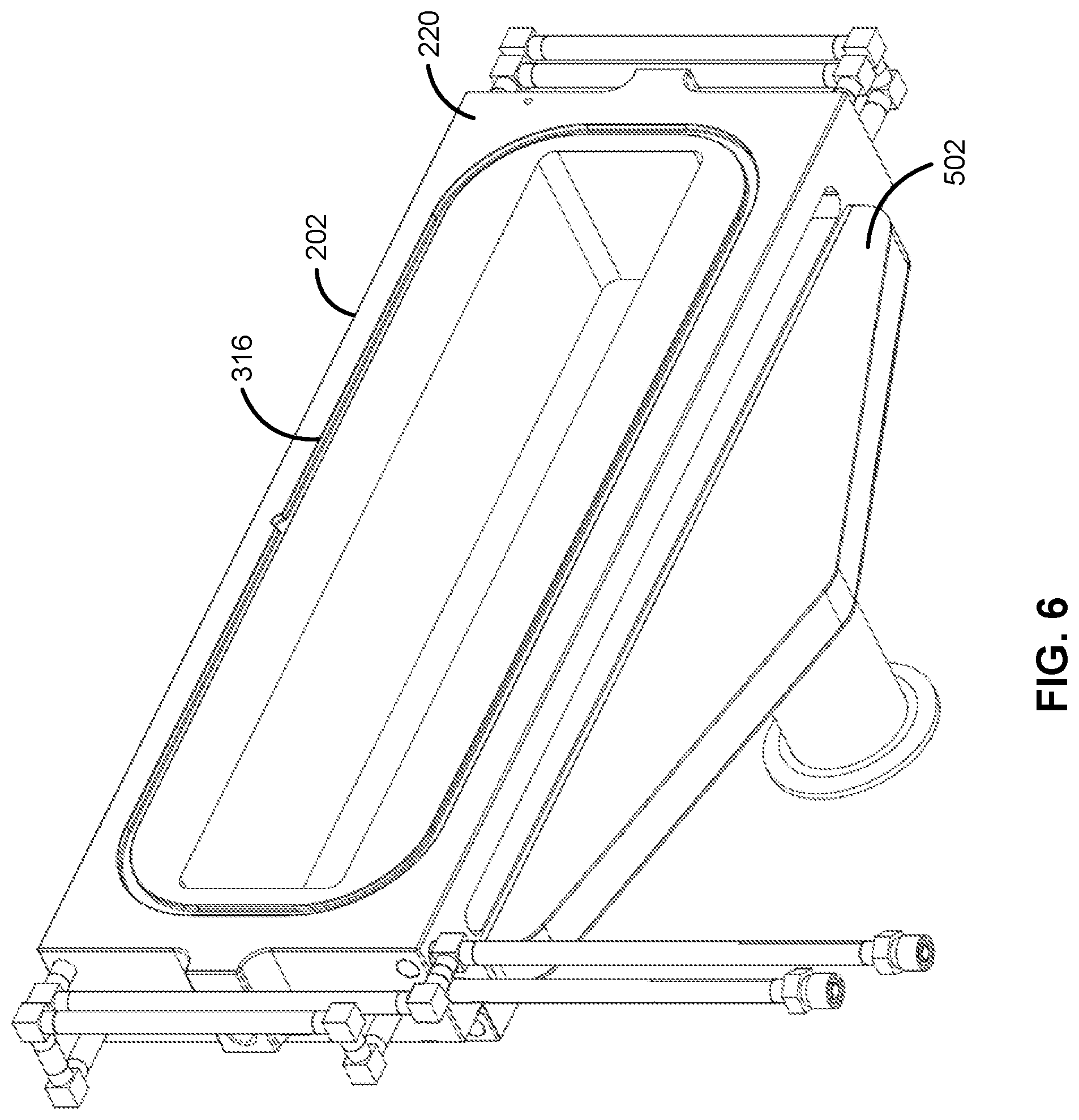
[0016] FIGS. 5 and 6 illustrate additional views of a flange assembly in accordance with at least one exemplary embodiment of the disclosure.
[0017] FIGS. 7, 8 and 9 illustrate cross-sectional views of a flange accordance with at least one embodiment of the disclosure.
[0018] FIG. 10 illustrates an additional view of a flange in accordance with at least one embodiment of the disclosure.
[0019] FIGS. 11 and 12 illustrate cooling tubes in accordance with illustrative examples of the disclosure.
[0020] FIG. 13 illustrates another view of a flange assembly in accordance with at least one embodiment of the disclosure.
[0021] FIG. 14 illustrates a view of a flange assembly and a heated manifold in accordance with at least one embodiment of the disclosure.
[0022] It will be appreciated that elements in the figures are illustrated for simplicity and clarity and have not necessarily been drawn to scale. For example, the dimensions of some of the elements in the figures may be exaggerated relative to other elements to help to improve the understanding of illustrated embodiments of the present disclosure.
DETAILED DESCRIPTION OF EXEMPLARY EMBODIMENTS OF THE DISCLOSURE
[0023] The description of exemplary embodiments provided below is merely exemplary and is intended for purposes of illustration only; the following description is not intended to limit the scope of the disclosure or the claims. Moreover, recitation of multiple embodiments having stated features is not intended to exclude other embodiments having additional features or other embodiments incorporating different combinations of the stated features.
[0024] The present disclosure generally relates to flanges and flange assemblies suitable for coupling to a reaction chamber, to reactor systems including the flange(s) and/or flange assemblies, and to methods of using the flanges, flange assemblies, and reactor systems.
[0025] The reactor systems including a one or more flanges and/or flange assemblies as described herein can be used to process substrates, such as semiconductor wafers, in gas-phase reactors. By way of examples, the systems described herein can be used to form or grow epitaxial layers (e.g., two component and/or doped semiconductor layers) on a surface of a substrate.
[0026] As used herein, a "substrate" refers to any material having a surface onto which material can be deposited. A substrate may include a bulk material such as silicon (e.g., single crystal silicon) or may include one or more layers overlying the bulk material. Further, the substrate may include various topologies, such as trenches, vias, lines, and the like formed within or on at least a portion of a layer of the substrate.
[0027] As set forth in more detail below, various sections of the flanges/flange assemblies can be cooled and other sections of the flanges/flange assemblies can be heated. This allows operation of reactors and reactor systems including such flanges and flange assemblies to operate at elevated temperatures (e.g., from about 150.degree. C. to about 200.degree. C. or about 180.degree. C. to about 200.degree. C.), while mitigating residue buildup (e.g., from reaction with or condensation of precursors and/or reaction byproducts within the reaction chamber) on the flange or assembly that might otherwise occur. By reducing the residue buildup, a mean time to maintenance of the reactor system or components thereof can be reduced. In addition, safety risks associated with the residue buildup are reduced. This may become increasingly important when using precursors that are liquid or solid at standard room temperature and pressure. The flanges and assemblies as described herein can provide cooling proximate a sealing member to mitigate deterioration of the sealing member that might otherwise occur. The cooling can be localized proximate the sealing members and/or the heating can be proximate an inner (reaction chamber side) surface of the flange and away from the sealing member. The flanges and flange assemblies described herein may be particularly useful in epitaxial reactors (e.g., hot-walled reactors), such as the Intrepid or Epsilon reactors available from ASM.
[0028] Turning now to the figures, FIG. 1 illustrates an exemplary reactor system 100. Reactor system 100 can be used for a variety of applications, such as, for example, chemical vapor deposition (CVD), plasma-enhanced CVD (PECVD), atomic layer deposition (ALD), clean processes, etch processes, and the like. Although exemplary embodiments are described below in connection with epitaxial reactor systems, the embodiments and the invention are not so limited, unless stated otherwise.
[0029] In the illustrated example, reactor system 100 includes a first flange assembly 102, a second flange assembly 104, a reaction chamber 106, an exhaust source 108, and a controller 110. Reactor system 100 can be configured as a cross flow, hot-wall epitaxial reactor system. Exemplary reactor systems including a horizontal flow reactor are available from ASM.
[0030] During operation of reactor system 100, substrates, such as semiconductor wafers, (not illustrated) are transferred from, e.g., a substrate handling system (not illustrated), to reaction chamber 106. Once substrate(s) are transferred to reaction chamber 106, one or more gasses, such as precursors, dopants, carrier gasses, and/or purge gasses are introduced into reaction chamber 106 via second flange assembly 104. Any unreacted gasses and/or reaction byproducts exit reaction chamber 106 and flow through first flange assembly 102 toward exhaust source 108. Controller 110 can be used to control a cooling and/or heating of flange assembly 102 and/or 104 to, e.g., control heaters embedded therein and/or control cooling (e.g., by controlling a flowrate of cooling liquid, such as water (e.g., filtered house water at room temperature) provided to flange assemblies 102, 104). Exemplary flowrates can range from, for example, about 0.5 L/min. to about 1.2 L/min.
[0031] FIGS. 2-13 illustrate an exemplary first flange assembly 102 and portions thereof in more detail. First flange assembly 102 includes a (e.g., first) flange 202, heaters 204, 206, 302 and 402, 404, and cooling channels 304-310 to receive cooling fluid, such as water. First flange assembly 102 also includes a first sealing member 312 to form a seal with reaction chamber 106 and a second sealing member 314 to form a seal with a cover plate 208. First flange assembly 102 also includes one or more thermocouples 210-216 to measure temperatures at various locations within first flange assembly 102. As described in more detail below, the temperature information from one or more thermocouples 210-216 can be used to provide information to controller 110 and/or to control heaters and/or cooling to first flange assembly 102. First flange assembly 102 can also include one or more heater retainers 218, 317, 319 to retain the heaters in place.
[0032] Flange 202 can be formed of any suitable material, such as stainless steel, and Hastelloy. Flange 202 includes a first surface 220 for coupling to a reactor or reaction chamber, a second surface 222 for coupling to cover plate 208, and an opening 224 between first surface 220 and second surface 222. First surface 220 includes a recess 316 to receive sealing member 312. Similarly, second surface 222 includes a recess 318 to receive sealing member 314. Further, flange 202 includes cooling channels 304-310 formed therein. Cooling channels 304-310 can be configured to receive cooling fluid directly or via tubes (e.g., pipes) 1102, 1104, 1202, and 1204, illustrated in FIGS. 11 and 12. Flange 202 also includes recesses 506, 508, 406, 408, and 320 to receive one or more heaters 204, 206, 302 and 402, 404. Forming recesses within flange 202 to receive heaters 204, 206, 302 and 402, 404 allows for placement of the heaters near an interior (reaction chamber side) of flange 202--e.g., near first surface 220. Similarly, forming cooling channels 304-310 within flange 202 allows for placement of the cooling channels proximate sealing members 312, 314. Further, by using recesses and retainers, as illustrated, heaters 204, 206, 302 and 402, 404 can be easily removed and replaced when desired-without removing flange 202 from reactor system 100, while allowing for placement of the heaters at desired locations within flange 202. As illustrated, flange 202 can also include one or more recesses to receive thermocouples 210-216 and/or retaining devices (e.g., screws or bolts). The recesses described herein can machined--i.e., cut out of material used to form flange 202. Machining, rather than simply drilling holes for the heaters can allow for, for example, desired placement and of the heaters within flange 202.
[0033] Heaters 204, 206, 302 and 402, 404 can be formed of any suitable material. By way of examples, heaters 204, 206, 302 and 402, 404 are resistive heaters, such as those available from SAKAGUCHI E.H. VOC CORP, and Watlow. Exemplary heaters have a power of about 500 to about 1000 or about 700 Watts. Although not illustrated, heaters 204, 206, 302 and 402, 404 can include cables to couple to controller 110 and/or to a suitable power source, which can be included as part of controller 110 or separate therefrom. By way of examples, heaters 204, 206, 302 and 402, 404 can be configured to heat areas of flange 202 to a temperature of about 150 to about 200.degree. C. or about 180 to about 200.degree. C.
[0034] First sealing member 312 and second sealing member 314 can be formed of resilient material, such as heat-resistant resilient material, such as silicone, Kalrez, or Viton.
[0035] Thermocouples 210-216 can include any suitable thermocouple. Exemplary thermocouples suitable for use as thermocouples 210-216 are available from OMEGA Engineering.
[0036] Cover plate 208 and/or heater retainers 218, 317, 319 can be formed of the same material as flange 202. By way of example, cover plate 208 and heater retainers 218, 317, 319 are formed of stainless steel.
[0037] First flange assembly 102 can also include a cover 502 surrounding a portion of an outlet 504. Cover 502 can be formed of the same or similar material as flange 202.
[0038] Turning now to FIGS. 8 and 9, cooling channels 304-310 are illustrated in greater detail. FIG. 8 illustrates a bottom cross-sectional view of flange 202, illustrating cooling channels 308, 310. Similarly, FIG. 9 illustrates a top cross-sectional view of flange 202, illustrating cooling channels 304, 306. While a diameter or similar cross-sectional dimension for cooling channels 304-310 can vary in accordance with design considerations, in accordance with some examples of the disclosure, the cross-sectional dimension ranges from about 400 mm to about 500 mm, or about 15 mm to about 35 mm. In accordance with examples of the disclosure, cooling channels and flow rate controllers 112, 114 can be configured to maintain a temperature of sections of flange proximate resilient seal 312, 314 of about 80 to about 120.degree. C. or about 100 to about 120.degree. C. Although illustrated in the supply line, flow rate controllers 112, 114 can additionally or alternatively be placed within the return line(s).
[0039] As illustrated, cooling channels and pipes 1102, 1104, 1202, 1204 can form a loop, such that a single inlet 1206 and a single outlet 1208 provide a continuous loop of coolant proximate one or more of resilient seal 312, 314. Further, as illustrated, in for example, FIGS. 2, 5, 6 and 13, portions of the continuous loop can include vertical sections 1302-1308 that reside outside flange 202. However, in accordance with other examples, such vertical sections could be included within--e.g., embedded within--flange 202.
[0040] FIG. 14 illustrates second flange assembly 104 and an injection manifold 1402, in accordance with further examples of the disclosure. Second flange assembly 104 includes a (e.g., second) flange 1404, heaters 1406, 1408, and cooling channels, illustrated as channels 1410, 1412, which can be the same or similar to channels 304-310. Second flange assembly 104 also includes a first sealing member 1414 to form a seal with reaction chamber 106 and a second sealing member (not illustrated, but which can be the same or similar to any of sealing members 1414, 312, 314) to form a seal with a gate valve (not illustrated). Second flange assembly 104 also includes one or more thermocouples 1416 to measure temperatures at various locations within second flange assembly 104. The temperature information from one or more thermocouples 1416 can be used to provide information to controller 110 and/or to control heaters and/or cooling to second flange assembly 104. Second flange assembly 104 can also include one or more heater retainers as described herein.
[0041] Flange 1404 can be formed of any suitable material, such as stainless steel. Similar to flange 202, flange 1404 includes a first surface 1418 for coupling to a reactor or reaction chamber 106, a second surface 1420 for coupling to cover plate and/or a gate valve, and an opening 1422 between first surface 1418 and second surface 1420. First surface 1418 includes a recess 1424 to receive sealing member 1414. Similarly, second surface 1420 can include a recess to receive another sealing member (e.g., the same or similar to sealing member 314). Further, flange 1414 includes cooling channels 1410, 1412 formed therein. Cooling channels 1410, 1412 can be configured to receive cooling fluid directly or via tubes (e.g., pipes), such as tubes 1102, 1104, 1202, and 1204, illustrated in FIGS. 11 and 12. Flange 1404 also includes recesses 1426, and 1428 to receive one or more heaters 1406 and 1408. Flange 1404 can also include various conduits configured to keep reactants/precursors separated, until such gasses reach reaction chamber 106. An exemplary flange conduit configuration is disclosed in U.S. application Ser. No. 14/218,690, filed Mar. 18, 2014 and entitled GAS DISTRIBUTION SYSTEM, REACTOR INCLUDING THE SYSTEM, AND METHODS OF USING THE SAME, the contents of which are hereby incorporated herein by reference, to the extent such contents do not conflict with the present disclosure.
[0042] Injection manifold 1402 is configured to provide one or more precursors, reactants, and purge and/or carrier gasses to reaction chamber 106. An exemplary injection manifold is described in U.S. application Ser. No. 15/997,445, filed Jun. 4, 2018 and entitled GAS DISTRIBUTION SYSTEM AND REACTOR SYSTEM INCLUDING SAME, the contents of which are hereby incorporated herein by reference, to the extent such contents do not conflict with the present disclosure. Lines 1430 and 1432 can be heated (e.g., using flexible (e.g., silicone) heater tape) to maintain gas within the lines at a desired temperature--e.g., to prevent or mitigate condensation of the gas. Additionally or alternatively, a heater 1434 can be provided around and/or proximate injection manifold 1402 to prevent and/or mitigate condensation of gas within injection manifold 1402.
[0043] Heaters 1406, 1408 and cooling channels 1410, 1412 can be the same or similar to those described above in connection with FIGS. 2-13 and can have the same or similar dimensions. Similarly, one or more thermocouples 1416 can be the same or similar to the thermocouples described above.
[0044] Reaction chamber 106 can be formed of, for example quartz. Exemplary operating pressures within reaction chamber 106 can range from about 10 Torr to about atmospheric (.about.760 Torr).
[0045] Exhaust source 108 can include, for example, one or more vacuum sources. Exemplary vacuum sources include one or more dry vacuum pumps and/or one or more turbomolecular pumps.
[0046] Controller 110 can be configured to perform various functions and/or steps as described herein. Controller 110 can include one or microprocessors, memory elements, and/or switching elements to perform the various functions. Although illustrated as a single unit, controller 110 can alternatively comprise multiple devices. By way of examples, controller can be used to control flow of coolant in and/or out of cooling tube (e.g., tubes 1102, 1104, 1202, 1204) and/or one or more (e.g., all) of the cooling channels described herein. Additionally or alternatively, controller can be used to control heaters, such as one or more of the heaters described herein. In particular, controller 110 can be configured to provide desired cooling to first flange assembly 102 and/or second flange assembly 104 by controlling an amount of coolant (e.g., water) flow into the respective tubes or channels. Additionally or alternatively, controller 110 can be used to control power to the (e.g., resistive) heaters. In accordance with various examples of the disclosure, controller 110 is or includes a proportional-integral-derivative (PID) controller, which allows closed-loop control of the heating and/or cooling of the respective flange assemblies or sections thereof. Controller 110 can also be coupled to thermocouples (not separately illustrated) within reaction chamber 106.
[0047] Various valves (e.g., water flow valves 112, 114) described herein can include solenoid valves.
[0048] In accordance with further embodiments of the disclosure, various combinations of reaction chamber 106, heaters in first flange assembly 102, heater in second flange assembly 104, cooling fluid supplied to first flange assembly 102, and/or cooling fluid supplied to second flange assembly 104 can be manipulated to mitigate deposition of material onto a surface of first flange assembly 102 and/or second flange assembly 104. For example, a power of one or more heaters can be set to a desired level and a temperature of the flange assemblies can be controlled by manipulating an amount of cooling water supplied to a respective flange assembly. Alternatively, the flowrate of the coolant can be set and the power to the heaters can be manipulated. Or, a combination of power to the heaters, flowrate of coolant, and/or reaction chamber temperature can be manipulated. Additionally or alternatively, the set point temperatures, flowrates, and/or powers can be changed between process steps for processes within reaction chamber 106.
[0049] Although exemplary embodiments of the present disclosure are set forth herein, it should be appreciated that the disclosure is not so limited. For example, although the flanges, flange assemblies, and reactor systems are described in connection with various specific configurations, the disclosure is not necessarily limited to these examples. Various modifications, variations, and enhancements of the system and method set forth herein may be made without departing from the spirit and scope of the present disclosure.
[0050] The subject matter of the present disclosure includes all novel and nonobvious combinations and subcombinations of the various systems, components, and configurations, and other features, functions, acts, and/or properties disclosed herein, as well as any and all equivalents thereof.
* * * * *
D00000
D00001
D00002
D00003
D00004
D00005
D00006
D00007
D00008
D00009
D00010
D00011
D00012

D00013

XML
uspto.report is an independent third-party trademark research tool that is not affiliated, endorsed, or sponsored by the United States Patent and Trademark Office (USPTO) or any other governmental organization. The information provided by uspto.report is based on publicly available data at the time of writing and is intended for informational purposes only.
While we strive to provide accurate and up-to-date information, we do not guarantee the accuracy, completeness, reliability, or suitability of the information displayed on this site. The use of this site is at your own risk. Any reliance you place on such information is therefore strictly at your own risk.
All official trademark data, including owner information, should be verified by visiting the official USPTO website at www.uspto.gov. This site is not intended to replace professional legal advice and should not be used as a substitute for consulting with a legal professional who is knowledgeable about trademark law.