Systems And Methods For Removing Contaminants In Electroplating Systems
Roh; Kwan Wook ; et al.
U.S. patent application number 16/407421 was filed with the patent office on 2019-11-14 for systems and methods for removing contaminants in electroplating systems. This patent application is currently assigned to Applied Materials, Inc.. The applicant listed for this patent is Applied Materials, Inc.. Invention is credited to Marvin L. Bernt, Kyle M. Hanson, Bioh Kim, Sam Lee, Paul McHugh, Kwan Wook Roh.
| Application Number | 20190345624 16/407421 |
| Document ID | / |
| Family ID | 68465125 |
| Filed Date | 2019-11-14 |


| United States Patent Application | 20190345624 |
| Kind Code | A1 |
| Roh; Kwan Wook ; et al. | November 14, 2019 |
SYSTEMS AND METHODS FOR REMOVING CONTAMINANTS IN ELECTROPLATING SYSTEMS
Abstract
Electroplating systems according to the present technology may include a two-bath electroplating chamber including a separator configured to provide fluid separation between a first bath configured to maintain a catholyte during operation and a second bath configured to maintain an anolyte during operation. The system may include a catholyte tank fluidly coupled with the first bath of the two-bath electroplating chamber. The system may also include a contaminant retrieval system configured to remove contaminant ions from the catholyte.
| Inventors: | Roh; Kwan Wook; (Kalispell, MT) ; McHugh; Paul; (Kalispell, MT) ; Lee; Sam; (Kalispell, MT) ; Hanson; Kyle M.; (Kalispell, MT) ; Bernt; Marvin L.; (Whitefish, MT) ; Kim; Bioh; (Andover, MA) | ||||||||||
| Applicant: |
|
||||||||||
|---|---|---|---|---|---|---|---|---|---|---|---|
| Assignee: | Applied Materials, Inc. Santa Clara CA |
||||||||||
| Family ID: | 68465125 | ||||||||||
| Appl. No.: | 16/407421 | ||||||||||
| Filed: | May 9, 2019 |
Related U.S. Patent Documents
| Application Number | Filing Date | Patent Number | ||
|---|---|---|---|---|
| 62669180 | May 9, 2018 | |||
| Current U.S. Class: | 1/1 |
| Current CPC Class: | C25D 5/22 20130101; C25D 21/18 20130101; C25D 7/12 20130101; C25D 5/08 20130101; C25D 3/38 20130101; C25D 3/30 20130101 |
| International Class: | C25D 5/22 20060101 C25D005/22; C25D 5/08 20060101 C25D005/08; C25D 3/30 20060101 C25D003/30; C25D 3/38 20060101 C25D003/38 |
Claims
1. An electroplating system comprising: a two-bath electroplating chamber including a separator configured to provide fluid separation between a first bath configured to maintain a catholyte during operation and a second bath configured to maintain an anolyte during operation; a catholyte tank fluidly coupled with the first bath of the two-bath electroplating chamber; and a contaminant retrieval system configured to remove contaminant ions from the catholyte.
2. The electroplating system of claim 1, wherein the contaminant retrieval system comprises a vessel positioned fluidly inline between the first bath and the catholyte tank.
3. The electroplating system of claim 2, wherein the vessel comprises an anode and a cathode electrically coupled with a power supply.
4. The electroplating system of claim 3, wherein the anode comprises a first material that is consumable or inert to the catholyte.
5. The electroplating system of claim 4, wherein the catholyte comprises a solution including tin, wherein the contaminant ions comprise copper, and wherein the first material comprises tin.
6. The electroplating system of claim 4, wherein the first material comprises a material inert to the catholyte and more noble than copper.
7. The electroplating system of claim 3, wherein the power supply is configured to operate at a voltage below a plating potential for tin within the electroplating system.
8. The electroplating system of claim 7, wherein the power supply is configured to operate at a voltage above a plating potential for copper within the electroplating system.
9. The electroplating system of claim 2, wherein the vessel comprises a packed bed of tin-containing particles.
10. The electroplating system of claim 1, wherein the contaminant retrieval system comprises a packed bed of tin-containing particles positioned in the catholyte tank.
11. A method of removing copper contaminants from a tin-containing catholyte within an electroplating system, the method comprising: flowing the catholyte from an electroplating chamber to a catholyte tank, passing the catholyte across a tin-containing material, and reducing the copper contaminants from the catholyte.
12. The method of removing copper contaminants from a tin-containing catholyte within an electroplating system of claim 11, wherein the tin-containing material comprises an anode of an anode-cathode pair of electrically coupled electrodes.
13. The method of removing copper contaminants from a tin-containing catholyte within an electroplating system of claim 12, wherein the anode and cathode are driven at a voltage below a tin plating potential and above a copper plating potential.
14. The method of removing copper contaminants from a tin-containing catholyte within an electroplating system of claim 12, wherein the cathode comprises tin or a material more noble than copper.
15. The method of removing copper contaminants from a tin-containing catholyte within an electroplating system of claim 12, wherein the tin-containing material is maintained in a vessel positioned between and fluidly coupled with the electroplating chamber and the catholyte tank.
16. The method of removing copper contaminants from a tin-containing catholyte within an electroplating system of claim 11, wherein the tin-containing material comprises a packed column of the tin-containing material.
17. The method of removing copper contaminants from a tin-containing catholyte within an electroplating system of claim 11, wherein the tin-containing material is disposed within the catholyte tank.
18. An electroplating system comprising: an electroplating chamber; an electrolyte tank fluidly coupled with the electroplating chamber and configured to maintain an electrolyte; a tin-containing electrolyte including copper ions; and a contaminant retrieval system configured to remove the copper ions from the electrolyte, wherein the contaminant retrieval system comprises a single component system of a tin-containing material, or a dual component system of a tin-containing material or a material more noble than copper on the electromotive force series.
19. The electroplating system of claim 18, wherein the contaminant retrieval system comprises a vessel positioned between the electroplating chamber and the electrolyte tank, and wherein the vessel houses the single component system or the dual component system.
20. The electroplating system of claim 18, wherein the contaminant retrieval system is configured in operation to maintain an increase in copper ion concentration within the electrolyte below about 1 ppm per five thousand wafers processed.
Description
CROSS-REFERENCES TO RELATED APPLICATIONS
[0001] This application claims the benefit of U.S. Provisional Patent Application No. 62/669,180, filed on May 9, 2018, and which is hereby incorporated by reference in its entirety for all purposes.
TECHNICAL FIELD
[0002] The present technology relates to systems and methods for semiconductor processing. More specifically, the present technology relates to systems and methods for reducing or removing contaminants from electroplating electrolyte solutions.
BACKGROUND
[0003] Integrated circuits are made possible by processes which produce intricately patterned material layers on substrate surfaces. During electroplating operations, contamination may occur in the form of metal ions incorporated within an electrolytic solution used in the electroplating system. Although the electrolyte may be replaced within the system, the replacement may be expensive and require extended time offline for the system.
[0004] Thus, there is a need for improved systems and methods that can be used to produce high quality devices and structures. These and other needs are addressed by the present technology.
SUMMARY
[0005] Electroplating systems according to the present technology may include a two-bath electroplating chamber including a separator configured to provide fluid separation between a first bath configured to maintain a catholyte during operation and a second bath configured to maintain an anolyte during operation. The system may include a catholyte tank fluidly coupled with the first bath of the two-bath electroplating chamber. The system may also include a contaminant retrieval system configured to remove contaminant ions from the catholyte.
[0006] In some embodiments, the contaminant retrieval system may include a vessel positioned fluidly inline between the first bath and the catholyte tank. The vessel may include an anode and a cathode electrically coupled with a power supply. The anode may include a first material that is consumable or inert to the catholyte. The catholyte may include a solution including tin and the contaminant ions may include copper, and thus the first material may be or include tin. The first material may be or include a material inert to the catholyte and more noble than copper. The power supply may be configured to operate at a voltage below a plating potential for tin within the electroplating system. The power supply may be configured to operate at a voltage above a plating potential for copper within the electroplating system. The vessel may include a packed bed of tin-containing particles. The contaminant retrieval system may be or include a packed bed of tin-containing particles positioned in the catholyte tank.
[0007] Some embodiments of the present technology may also encompass methods of removing copper contaminants from a tin-containing catholyte within an electroplating system. The methods may include flowing the catholyte from an electroplating chamber to a catholyte tank. The methods may include passing the catholyte across a tin-containing material. The methods may also include reducing the copper contaminants from the catholyte.
[0008] In some embodiments, the tin-containing material may be an anode of an anode-cathode pair of electrically coupled electrodes. The anode and cathode may be driven at a voltage below a tin plating potential and above a copper plating potential. The cathode may be or include tin or a material more noble than copper. The tin-containing material may be maintained in a vessel positioned between and fluidly coupled with the electroplating chamber and the catholyte tank. The tin-containing material may be or include a packed column of the tin-containing material. The tin-containing material may be disposed within the catholyte tank.
[0009] Embodiments of the present technology may also encompass electroplating systems. The systems may include an electroplating chamber. The systems may include an electrolyte tank fluidly coupled with the electroplating chamber and configured to maintain an electrolyte. The systems may include a tin-containing electrolyte including copper ions. The systems may also include a contaminant retrieval system configured to remove the copper ions from the electrolyte. The contaminant retrieval system may include a single component system of a tin-containing material, or a dual component system of a tin-containing material or a material more noble than copper on the electromotive force series. The contaminant retrieval system may include a vessel positioned between the electroplating chamber and the electrolyte tank, and the vessel may house the single component system or the dual component system. The contaminant retrieval system may be configured in operation to maintain an increase in copper ion concentration within the electrolyte below about 1 ppm per five thousand wafers processed. Such technology may provide numerous benefits over conventional technology. For example, the present systems provide a cost-effective solution to reducing contaminant levels within an electrolyte of the system. Additionally, the present systems and methods may improve quality while having a limited effect on bath chemistries and process parameters. These and other embodiments, along with many of their advantages and features, are described in more detail in conjunction with the below description and attached figures.
BRIEF DESCRIPTION OF THE DRAWINGS
[0010] A further understanding of the nature and advantages of the disclosed embodiments may be realized by reference to the remaining portions of the specification and the drawings.
[0011] FIG. 1 shows a schematic view of an electroplating system according to some embodiments of the present technology.
[0012] FIG. 2A shows a schematic view of a contaminant retrieval system according to some embodiments of the present technology.
[0013] FIG. 2B shows a schematic view of a contaminant retrieval system according to some embodiments of the present technology.
[0014] FIG. 3 shows a schematic view of an electroplating system according to some embodiments of the present technology.
[0015] FIG. 4 shows selected operations of a method of removing copper contaminants from a tin-containing catholyte within an electroplating system according to some embodiments of the present technology.
[0016] Several of the figures are included as schematics. It is to be understood that the figures are for illustrative purposes, and are not to be considered of scale unless specifically stated to be of scale. Additionally, as schematics, the figures are provided to aid comprehension and may not include all aspects or information compared to realistic representations, and may include exaggerated material for illustrative purposes.
[0017] In the figures, similar components and/or features may have the same numerical reference label. Further, various components of the same type may be distinguished by following the reference label by a letter that distinguishes among the similar components and/or features. If only the first numerical reference label is used in the specification, the description is applicable to any one of the similar components and/or features having the same first numerical reference label irrespective of the letter suffix.
DETAILED DESCRIPTION
[0018] A variety of systems are used in the semiconductor industry for electrodeposition. For example, electroplating may be performed in single-bath electrolyte systems having a single electrolyte in contact with both the anode and cathode. Plating may also be performed in two-bath electrolyte systems including an anolyte and catholyte. The two-bath chamber typically includes a separator or membrane separating the two fluids, while allowing certain ions to permeate the membrane and cause plating at the cathode.
[0019] In a two-bath system the catholyte may be in contact with the substrate on which deposition may be performed, while the anolyte is maintained physically separated from the substrate by the membrane or separator. During some electroplating operations, one metal may be plated over a second metal, which may have been deposited in an upstream or previous operation. Upstream electroplating systems can act as a source of metal ion contamination for subsequent electroplating systems. For example, when forming soldering connections, a solder material, such as tin, tin-silver, or a lead-free material may be deposited over a separate metal, such as copper, for example, that may have been formed in a previous operation. The process for depositing the solder material may use a catholyte including ions of the solder metal, such as tin, as well as a number of additives, acid, and other materials providing a specifically balanced solution configured to reduce the tin ions in order to produce a layer of the solder material over exposed regions of the first material in the electroplating chamber.
[0020] The copper may have been formed in any number of previous operations, including in a previous electrodeposition operation. When formed in an upstream or previous electrodeposition operation, residual electrolyte including copper ions may be transferred with the substrate into the tin-containing electrolytic bath incorporating an amount of copper ion contamination within the tin-containing electrolyte. Additionally, due to properties or conditions of the tin-containing electrolyte, copper may naturally erode, etch, or undergo oxidation reactions sending ions into the subsequent tin-containing electrolyte during or prior to the subsequent plating operations. This may also incorporate an amount of copper contamination within the tin-containing electrolyte. If left unresolved, as plating operations are performed, and hundreds or thousands of substrates are processed, the copper ion concentration within the tin-containing electrolyte may continue to rise. If left unresolved, the buildup of contaminants can cause a number of issues including chemical reaction between the plating solution and the contaminant materials. Additionally, increased levels of copper contamination within tin-containing electrolytes have been shown to produce surface roughness on plated materials, and other defects or voids between the plated materials.
[0021] Some conventional technologies have attempted to address contaminant levels in an electrolyte by performing bath changes in which the tin-containing electrolyte is exchanged for new electrolyte in the system when contaminant levels are too high. This process may be expensive based on the cost of electrolyte additives and materials, and may require increased amounts of tool down time during the exchanges. Alternatively operations may be performed to refresh the electrolyte by routinely withdrawing some electrolyte and incorporating new electrolyte, which may replenish a percentage of the amount of electrolyte in the system in a given cycle, and may continually exchange the electrolyte over a number of these cycles. Depending on how often the exchange occurs, and the volume involved in the exchange, these replenishments may also be expensive over time.
[0022] The present technology improves on these conventional techniques by performing operations in which contaminants may be removed from the system by an advanced filtering or removal technique, in which the contaminant ions may be electrochemically removed from the tin-containing electrolyte. The present technology may afford reduced contamination levels by continually or intermittently removing copper ions from the electrolyte without requiring physical exchange of the electrolyte. These operations may reduce electrolyte replacement costs, and may increase system uptime by allowing the removal to occur in a functioning system during plating operations. It is to be understood that although the disclosure will routinely describe removing copper ions from a tin-containing electrolyte, the present technology is not so limited. For example, any plating material including contaminant ions may benefit from the present technology by performing operations based on plating potential differences between the metallic components as will be described below. For example, additional applications for the present technology may include copper contamination into nickel-containing chemistries, nickel contamination into tin-silver chemistries, or any other application where an upstream formation of a first material may provide a contamination source into a downstream electrolyte. Accordingly, the present technology should not be considered limited to the exemplary materials discussed.
[0023] FIG. 1 shows a schematic view of an electroplating system 100 according to some embodiments of the present technology. Electroplating system 100 illustrates a two-bath system, although single-bath systems may similarly benefit from the present technology as will be discussed further below. Electroplating system 100 is shown including a pair of two-bath electroplating chambers, including chamber 105 and chamber 110. It is to be understood, however, that systems according to the present technology may include one or more chambers utilizing an electrolyte bath, and may include any number of chambers. As shown, chamber 105 may include a first bath 106 configured to maintain a catholyte during operation, as well as a second bath 108 configured to maintain an anolyte during operation. A separator 107 may provide fluid separation between the anolyte and catholyte, while allowing ionic transport across the separator. Similarly, chamber 110 may include a third bath 112 configured to maintain a catholyte during operation, as well as a fourth bath 114 configured to maintain an anolyte during operation. A separator 113 may provide fluid separation between the two baths.
[0024] Electroplating system 100 may also include a catholyte tank 120. Catholyte tank 120 may be fluidly coupled with the electroplating chambers 105, 110, and may be specifically fluidly coupled with the first bath 106 of chamber 105 and with the third bath 112 of chamber 110. Although not shown in this embodiment, the system may include a similar anolyte tank coupled with the second bath 108 of chamber 105 and with the fourth bath 114 of chamber 110. The anolyte tank may include a separate piping or plumbing system and a dedicated pump forming a separate loop for that chemistry.
[0025] Pump 125 may be included in the electroplating system 100 to provide fluid communication between the catholyte tank 120 and the first bath 106 of chamber 105 and with the third bath 112 of chamber 110. In other embodiments dedicated pumps may be provided for each two-bath electroplating system, although a single pump may be utilized as illustrated. The pump 125 may be configured to provide catholyte to the electroplating chamber to ensure a consistent chemistry is maintained during deposition processing. Pump 125 may be a first pump in some embodiments in which a second pump is included with an associated anolyte tank for providing anolyte from the anolyte tank to the anolyte baths of the associated electroplating chambers. Ancillary equipment may also be included with electroplating system 100, such as a filter, as well as unidentified sensors, valves, and common piping materials and associated components. The illustrated piping configuration is exemplary only, and is included to show potential lines including returns 127 to the catholyte tank 120, which may intersect to provide a common return 130. Other fluid configurations are similarly encompassed by the present technology.
[0026] Electroplating system 100 may also include a contaminant retrieval system configured to remove contaminant ions from the catholyte. The contaminant retrieval system may include one or more components that may operate to remove certain metal ions from the catholyte. For example, in an exemplary system utilizing a tin-containing catholyte, the contaminant retrieval system may be configured to remove copper or other metal ions from the tin-containing catholyte. The contaminant retrieval system may include a vessel 135 positioned fluidly inline between the first and third baths 106, 112 and the catholyte tank 120. In systems according to the present technology, a single catholyte tank may be used to provide and circulate catholyte to multiple chambers. Vessel 135 may be positioned in a common line, including common return line 130, or common delivery line 129, although individual vessels 135 may be positioned within returns 127a, and 127b, for example.
[0027] Vessel 135 may include one or more materials that may be configured or operated to remove copper ions from the tin-containing catholyte, or may remove other metal contaminants from metal-ion-containing electrolytes. The contaminant retrieval system may additionally or alternatively include device 140, which may be disposed or positioned within the catholyte tank 120. For example, device 140 may include similar materials as vessel 135, or may include a separate material configured to operate on similar or different mechanisms for removing metal ion contaminants from a metal-ion-containing electrolyte. Vessel 135 may be positioned with a bypass line as illustrated, which may allow intermittent operation of the contaminant retrieval system in some embodiments, although other bypass or inline incorporation schemes are similarly encompassed by the present technology. Vessel 135 will be described in detail with regard to FIG. 2 below along with exemplary operating mechanisms for removing contaminants from an electroplating system.
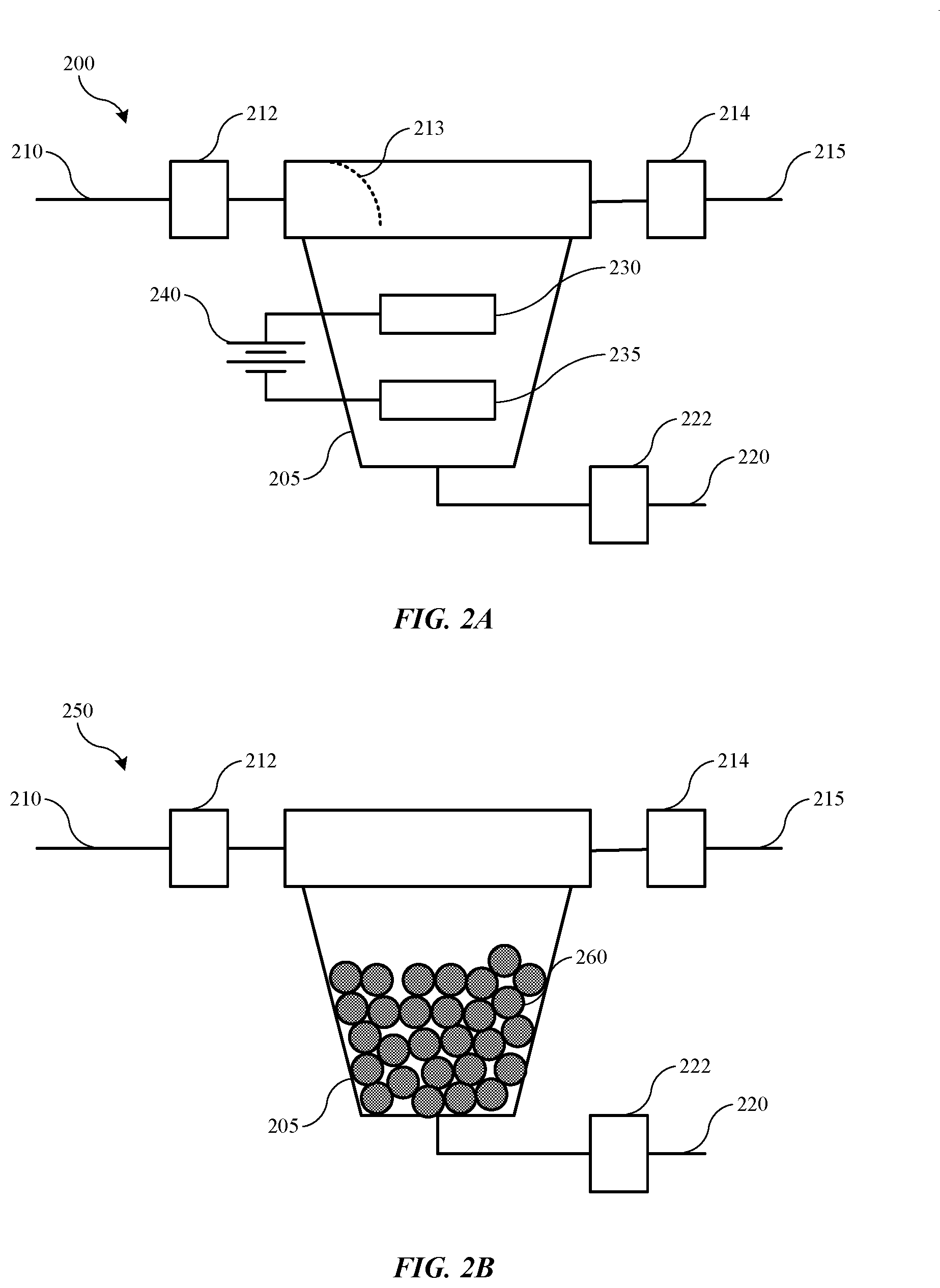
[0028] Turning to FIG. 2A is shown a schematic view of an exemplary contaminant retrieval system 200 according to some embodiments of the present technology. System 200 may be similar to, or include a vessel 205 similar to, vessel 135 described above, and the system or components may be positioned within a catholyte fluid system between a catholyte tank and a processing chamber catholyte bath in any location as noted previously. In some embodiments, by incorporating the system 200 within a common return line between the chamber catholyte bath and the catholyte tank, a single system 200 may be utilized for a multi-chamber system. Additionally, when incorporated in a return line, catholyte may be flowing under pressure, which may help drive catholyte flow within the system 200.
[0029] System 200 may include an inlet line 210 and an outlet line 215, which may be part of a common return line of an electroplating system, or may be bypasses from a common or other fluid line of an electroplating system. Valves 212 and 214 may be utilized to allow or prevent flow through contaminant retrieval system 200. An optional drain line 220 may also be incorporated with the contaminant retrieval system 200, and may also include an optional drain valve 222. The drain line may be used to remove electrolyte material contained within the vessel 205 during a maintenance operation, for example, and drain line 220 may extend as a retrieval line back into a catholyte tank, such as tank 120, or may deliver fluid to an alternative retrieval or disposal position. An optional flow controller or diffuser 213 may be incorporated within the vessel 205 in some embodiments to direct flow towards the anode and cathode setup instead of simply bypassing to the outlet line 215. However, in other embodiments the vessel 205 may simply be sized to produce a pressure drop configured to draw fluid through the chamber to limit unintended bypass. Any other mechanical or fluidic mechanisms may also be used to direct or maintain flow within the vessel 205.
[0030] Within vessel 205 of contaminant retrieval system 200 may be one or more devices or apparatus configured to perform a removal operation intended to remove copper or other metallic ions from a tin or other metal-containing electrolyte, while limiting or preventing removal of the tin or metal ion of the electrolyte. Two such options as may be included individually or in combination as illustrated in FIG. 2A as well as 2B described below. As illustrated in FIG. 2A, vessel 205 may include an electrode system including an anode 230, a cathode 235, as well as a power source 240, which may be electrically coupled with anode 230 and cathode 235. Power source 240 is illustrated as a multi-cell source, although it is to be understood that any number of power supplies or sources may be used to provide a voltage configured to drive an electrochemical operation between anode 230 and cathode 235. It is also to be understood that the anode and cathode are being shown schematically, and are not limited to the configuration illustrated. For example, in some embodiments the position of the anode and cathode may be reversed within the vessel, with the cathode positioned above the anode. Additionally, the anode and cathode may be disposed in a planar arrangement and positioned adjacent or in line with one another. In some embodiments the anode and cathode may be characterized by a curvature, and may be aligned proximate one another along a common radius from a central axis through the vessel, or with one of the anode or cathode positioned concentrically or radially outward of the other of the anode or cathode. Any other configurations possible within the vessel are similarly encompassed by the present technology.
[0031] Anode 230 may be made of a first material, and cathode 235 may be made of a second material. In some embodiments the first material and the second material may be similar or identical to one another. In some embodiments one or both of the anode 230 or cathode 235 may be or include tin or a tin-containing material, although the material may be based on a different element, which may be selected to coordinate with the ion of the catholyte. As explained previously, one exemplary application of the present system is where a tin-containing material may be plated over a second material, which may be or include copper. In such an electroplating operation, the catholyte of a two-bath system may include metal ions of the material to be plated or deposited, which in this case may be tin. In other embodiments in which a different metal is to be plated, the anode and/or cathode may include the different metal in the electrode composition. In some embodiments the anode and/or cathode may be a more inert material, and may be a material that is more noble on the electromotive force series than one or both of the metal ion of the electrolyte, or the metal ion of the contaminant. Continuing the example throughout this description, the material of the anode or cathode may be more noble than one or both of tin or copper. For example, materials including platinum, silver, palladium, steel, chromium, nickel, titanium, vanadium, zirconium, niobium, molybdenum, hafnium, tantalum, tungsten, ruthenium, rhodium, technelium, rhenium, osmium, iridium, antimony, tellurium, or other transition metals or other elements, including compounds, such as oxides, or combinations of any of the materials, may be used.
[0032] Although many of the identified materials may be utilized in embodiments of the present technology, in some embodiments the material may be selected to limit interference with the electroplating system. For example, the material may be selected to limit side reactions with components or additives of the electrolyte, maintain conductivity, limit oxidation or passivation within the electrolyte system, as well as withstand the environment of the electrolyte. The anode 230 may be either consumable or inert in the catholyte. One exemplary inert material may be or include platinum, which may be used as one or both of the anode or cathode in various embodiments. A consumable material may be or include tin or a tin-containing material, which may also be incorporated as one or both of the anode or cathode in various embodiments. In some embodiments, the anode may be or include tin or a tin-containing material, which may be consumed to provide tin ions into the catholyte. Certain inert electrode materials may not oxidize metal materials into the catholyte, but may generate or evolve gaseous species within the catholyte if the potential is high enough, and thus may be managed to limit gas from entering into the catholyte via bubble separators or other collection mechanisms. Accordingly, in some embodiments tin or a tin-containing material may be utilized, which may be relatively or substantially neutral to the catholyte by providing the metal ions, which may at least partially replenish plating ions into the catholyte.
[0033] As previously stated, in other embodiments in which a different metal is the base ion for the catholyte, the anode may be or include that material, which may at least partially replenish the electrolytic solution during operation of the contaminant retrieval system. Either the anode or the cathode may take on a number of designs, profiles, or configurations, including a plate material, pellet material, or other configuration to provide surface area characteristics configurable for a variety of system designs. For example, in one embodiment, tin pellets may be contained within a conductive sleeve to which power source 240 may be coupled. Such a configuration may be positioned substantially normal to a direction of flow within the vessel, and may provide an amount or tortuosity of flow to improve contact of resident copper ions with the tin or other materials to increase retrieval from the system.
[0034] In some embodiments the power supply may be operated within a particular voltage range within a cell potential difference between the contaminant metal species and the electrolyte metal species. For example, in some embodiments the power source may be configured to supply a voltage within a window at least partially defined by the cell potential between the contaminant material, for example copper, and the electrolyte metal ion, for example tin. In this example, the cell potential would be the copper potential of about 0.34 minus the tin potential of negative 0.14, producing a cell potential of about 0.48 V. Again, when different electrolyte or contaminant materials are utilized, the potential may be premised by the specific potential of those materials. By maintaining the power supply operating voltage within a window defined by the cell potential, the system may be configured to reduce or plate out the contaminant material while maintaining the electrolyte metal ion material. The system may be configured to limit or prevent plating of the electrolyte metal ion material, which would otherwise reduce the concentration of the ion intended to be plated at the chamber cathode, which typically may be the substrate.
[0035] In one non-limiting hypothetical scenario, chamber setup and testing may identify that within one possible contaminant retrieval system, tin may begin plating out of the electrolyte at a voltage of greater than or about 2 V, and thus the plating potential for tin within the system may be at a voltage above 2 V, such as 2.3 V, as a hypothetical example. Accordingly, the voltage of power supply 240 may be maintained below the hypothetical 2.3 V in such a cell. Based on the cell potential relative to the contaminant copper, the cell potential for copper may be about 0.5 V less than the 2.3 V for plating tin, and thus the plating potential for copper within the system may be at a voltage above about 1.5 V, such as about 1.8 V, continuing the hypothetical example. Accordingly, the voltage of power supply 240 may be maintained above the hypothetical 1.8 V in some embodiments. Depending on many factors including cell composition, electrolyte composition, or a variety of resistances within the system, these plating potentials may be system specific, and may be predetermined via testing for a given system. However, during operation the power supply voltage may be maintained within the window as defined below the plating potential for tin within the given cell design. As copper or other contaminant concentration continues to reduce within the electrolyte, the potential to plate additional copper may shift in a more negative potential direction, which may require increasing the voltage over time beyond the predetermined or precalculated threshold to plate copper. However, the voltage may still be maintained below the potential to plate the electrolyte ion material, such as tin. After an amount of time has passed where the window may not be suitably maintained without beginning tin plating, the anode and or cathode material may be replaced within the contaminant retrieval system.
[0036] FIG. 2B illustrates an additional embodiment of a schematic view of an exemplary contaminant retrieval system 250 according to some embodiments of the present technology, which may be combined with or utilized instead of the anode 230 and cathode 235. System 250 may be similar to or include common components as discussed above with respect to system 200, and may be incorporated within an electroplating system in a similar manner. System 200 may also include a vessel 205 similar to vessel 135 described above, and the system or components may be positioned within a catholyte fluid system between or within a catholyte tank and a processing chamber catholyte bath in any location as noted previously.
[0037] System 200 may include an inlet line 210 and an outlet line 215, which may be part of a common return line of an electroplating system, or may be bypasses from a common or other fluid line of an electroplating system. Valves 212 and 214 may be utilized to allow or prevent flow through contaminant retrieval system 200. An optional drain line 220 may also be incorporated with the contaminant retrieval system 200, and may also include an optional drain valve 222. As previously noted, the drain line may be used to remove electrolyte material contained within the vessel 205 during a maintenance operation, for example, and drain line 220 may extend as a retrieval line back into a catholyte tank, such as tank 120, or may deliver fluid to an alternative retrieval or disposal position.
[0038] Within vessel 205 of contaminant retrieval system 200 may be a pelletized material 260 or otherwise packed particle design. Packed material 260 may be or include a conductive material, and may be any of the materials identified above for the anode and cathode materials of system 200. In some embodiments the packed materials may be tin or tin-containing particles positioned within the vessel 205. Additionally or alternatively, the particles may be included as device 140 within the catholyte tank. System 200 may also be positioned within catholyte tank 120 described above. The packed materials may be a single material included within the vessel, or may be a combination of the components described above. For example, the material may be more active on the electromotive force series than the contaminant material. By incorporating the material 260 within the vessel 205, a galvanic action may be afforded by the system, which may allow plating and removal of the contaminant from the electrolyte.
[0039] For example, when maintained in contact with the electrolyte including the contaminant species, a galvanic reaction may occur on multiple pellets of the material 260. For example, some pellets will naturally begin to donate electrons in a reduction reaction to contaminant ions, such as copper ions, which will begin to plate on these pellets that may exhibit a cathode effect. Additional pellets may then naturally exhibit an anode effect, and may donate electrons to the system, causing the pellet to undergo an oxidation reaction in which ions of the pellet material may be delivered into the electrolyte material. The pellets or material 260 may not be connected electrically, and the reaction may occur directly during the flow of the electrolyte material across the surface of the material 260. In some embodiments, when power source 240 of system 200 is not engaged, the same action may occur if the system is allowed to continue circulating electrolyte across the anode and cathode materials. Accordingly, one or both actions may be performed or allowed to occur to reduce contaminant ion concentration within the electroplating system.
[0040] Additional materials that may be utilized may include resin or otherwise coated particles including an active exchange material within the resin or coating. The exchange material may be configured to perform a proton exchange relative to copper ions incorporated within the electrolyte. The material may be configured to preferentially interact with copper or contaminant ionic species relative to other metallic species, such as ions of the electrolyte utilized in plating. In operation, such as continuing the example throughout this disclosure, tin ions and other materials may not interact with the particles as they flow across or through the bed of particles. Copper ions, however, may be absorbed through the resin or coating material, and may be collected by the internal active exchange material, which may expel a proton in response to the collected copper. The particles may be capable of operating for an amount of time, or may remove an amount of material before the particles are saturated. Once saturated, or when nearing saturation, the materials may be replaced or refreshed for additional use. The resin or coating may be any material configured to operate within the electrolyte and system environment, and allow transmission of copper or contaminant ionic species, while limiting or preventing transmission of other metallic or some other ionic species.
[0041] By performing operations and using systems according to the present technology, a concentration of contaminant ions may be reduced and/or maintained below certain thresholds. For example, the present technology may afford a contaminant-neutral configuration allowing contaminant incorporation to be maintained during substrate processing and routine replacement or refreshing of the contaminant retrieval system components. Systems may be capable of tolerating an amount of contaminant incorporation within the electrolyte, such as less than or about 10 ppm, less than or about 8 ppm, less than or about 5 ppm, less than or about 3 ppm, less than or about 2 ppm, less than or about 1 ppm, less than or about 100 ppb, less than or about 10 ppb, or less. The present technology may be configured to limit additional contaminant accumulation during a number of substrate processing operations. For example, the present technology may limit additional incorporation of contaminant and/or reduce native contaminant levels below any of these stated limits at any time during operation, including after processing more than or about 1,000 substrates, processing more than or about 5,000 substrates, processing more than or about 10,000 substrates, or more. For example, if a natural concentration of contaminant may be at 5 ppm for an electrolyte solution, the present technology may maintain the contaminant level below 6 ppm, below 5.1 ppm, as well as further reduce contaminant levels below 5 ppm, below 4 ppm, or less during processing of any of the noted substrate numbers. Accordingly, the present technology may maintain or improve contaminant levels within electrolytic materials.
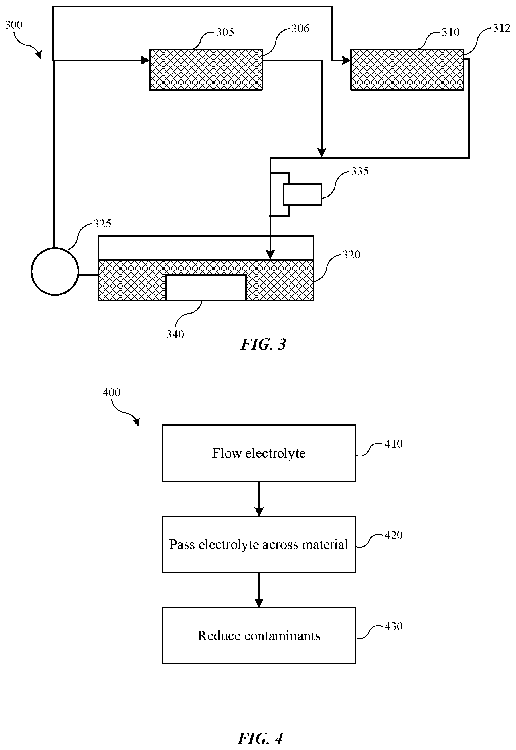
[0042] The present technology may similarly be utilized in single-bath systems in some embodiments. FIG. 3 shows a schematic view of an electroplating system 300 according to some embodiments of the present technology. Electroplating system 300 may include some or all of the components discussed previously, although a single electrolyte may be used within the systems alternatively to a separate catholyte and anolyte. The components of electroplating system 300 may operate similarly to the components described above, and may be configured to limit contaminant accumulation to any of the previously identified ranges. As illustrated, electroplating system 300 may include an electroplating chamber 305, as well as an additional electroplating chamber 310. Similar to previous systems, electroplating system 300 may include any number of electroplating chambers within the system. The electroplating chambers 305, 310 may be configured to house an electrolyte 306, 312 that is distributed through the system. Electroplating system 300 may include an electrolyte tank 320 fluidly coupled with the electroplating chambers 305, 310, and configured to maintain the electrolyte that is distributed.
[0043] Electroplating system 300 may include a pump 325 fluidly coupled between the electrolyte tank 320 and the electroplating chamber 310. The pump may be configured to provide electrolyte from the electrolyte tank to the electroplating chamber 305. Electroplating system 300 may also include any other ancillary equipment in some embodiments that may be used in electroplating chamber designs. Electroplating system 300 may be used in any number of electroplating operations, and may be configured with materials to perform operations related to a number of metals and materials. In one example encompassed by the present technology, the system may be used in a tin-plating operation, and may utilize a tin-containing electrolyte. An amount of contaminant, such as a copper ion contaminant, may be present in the electrolyte.
[0044] Electroplating system 300 may also include one or more contaminant retrieval system components, which may include vessel 335 or device 340. Vessel 335 and device 340 may be or include any of the materials or components previously described, and may be configured to operate to reduce copper ion concentration within the electrolyte. The contaminant retrieval system may include a single component system, such as particles in a packed configuration as previously described. The contaminant retrieval system may also include a dual component system, such as an anode/cathode electrode configuration with a power supply to drive an electroplating operation as described previously. The system may be operated to maintain or reduce contaminant concentration to any of the levels previously described during processing of any number of substrates.
[0045] The systems described previously may be used to perform one or more methods, such as removing copper contaminants from a tin-containing catholyte or electrolyte within an electroplating system. FIG. 4 shows operations of an exemplary method 400 of removing contaminant species from an electrolyte material according to some embodiments of the present technology. Method 400 may be performed with any of the systems previously described, which may include any of the components or configurations described elsewhere. Method 400 may include additional operations performed prior to the stated operations, including a first deposition or plating in a first chamber. For example, an upstream process may include forming a copper-containing or other metal-containing material on a substrate. The substrate may then be transferred to a second plating chamber for plating a tin-containing or other metal-containing material. When transitioned into an electrolyte including the second material, such as the tin-containing material, contamination may be introduced into the system as previously described. Method 400 may include flowing a catholyte or electrolyte through an electroplating system at operation 410. The electrolyte may include a contaminant within the solution. The electrolyte may be flowed between a processing chamber and an electrolyte tank, which may be a catholyte tank in some embodiments. At operation 420, the electrolyte may be passed over a material configured to reduce or remove contaminants from the electrolyte. In one example, a catholyte may be passed over a tin-containing material. Contaminant species may be reduced or removed from the electrolyte at operation 430.
[0046] As previously noted, the material may be any of the materials previously described, and may include one or more components including a retrieval vessel and/or a particulate material included inline of a fluid line of the system, such as fluidly coupled between the electroplating chamber and the electrolyte tank. In some embodiments the material may also or alternatively be included within an electrolyte tank, such as a catholyte tank as previously described. In some embodiments the material may be tin or a tin-containing material operated as an anode of an anode-cathode pair of electrically coupled electrodes. The contaminant species, which may be copper, may be plated onto the cathode, while anode species may be eroded into the electrolyte solution. In some embodiments one or more of the cathode or anode may not be consumed during the operation. When operated as a cathode and anode, the electrodes may be driven by a power source operating at a voltage configured or tested to be below a tin plating potential and above a copper plating potential, which may also be below a potential of an electrolyte species and above a potential of a contaminant species in other embodiments. In some embodiments the cathode may be or include tin or may be a material more noble on an electromotive force series than copper.
[0047] For example, during system setup, sample runs or tests may be performed to determine a threshold voltage for the system at which tin plating may occur. For example, a power source as previously described may be operated at a particular voltage, while a monitoring operation is performed for the current. Current flow may be based on material plating out of the electrolyte. Thus, for example, at low voltage, current flow may be reduced, or may not occur. At a threshold at which copper plating may occur, an amount of current may be observed. Based on the concentration of copper within the solution, this current may be in a microamp or milliamp range. As voltage is further increased, a threshold may be reached at which current may rise in a more pronounced manner, which may indicate plating of tin from the electrolyte. Because of the higher concentration of tin within the system, current generated by the plating of tin may be more than an order of magnitude higher than during copper plating, for example.
[0048] Accordingly, a threshold for tin plating may then be determined for the individual system, and voltage for operation may then be maintained below this threshold, but above the threshold potential for copper plating. As previously stated, the voltage may be adjusted over time relative to the characteristics of the electrolyte. For example, as copper ion concentration is further reduced, voltage may be increased to accommodate further plating, although the voltage may still be maintained below the tin-plating threshold. Additionally, because of low copper concentration, copper deposition may proceed at or near the mass-transfer limited current density for the copper. Electrolyte flow characteristics and characteristics of the cathode material may therefore be important factors in removal of the limited copper or other contaminant within the system. Flow agitators or other mechanisms may therefore be included to facilitate movement within the vessel, such as rifling along an interior of the vessel, as well as incorporated devices to increase electrolyte movement within the vessel. The cathode material may also be modified or enhanced in some embodiments, including by incorporating roughening to increase surface area and plating opportunity, as well as profiles including fluted, creased, or corrugated designs that may increase residence time at the cathode as well as surface area to facilitate plating. In some embodiments as may be applicable in any of the previously described figures, the cathode may be characterized by a greater surface area than the anode, and may be characterized by at least twice the surface area, at least three times the available surface, at least five times the available surface area, at least ten times the available surface area, or more.
[0049] The system may be operated in a continuous mode in some embodiments to continue to reduce copper concentration and/or provide additional tin from an anode. The system may also be operated intermittently after testing of electrolyte indicates a rise in copper ion concentration, such as above a threshold. By operating the system intermittently, electrolyte balance may be better maintained. For example, operating intermittently may limit effects on other materials or additives in the electrolyte, and may ensure an overabundance of tin ions are not provided into the system.
[0050] In some embodiments the material may be included in a packed configuration, either within a vessel or packed column configured to provide sufficient surface area for interaction with the electrolyte and contaminant species included within the electrolyte. By utilizing the present technology, contaminant levels within an electrolyte may be maintained or reduced below predetermined levels. Utilizing electroplating and/or galvanic interactions, the present technology may allow contaminant species to be removed, while maintaining other ionic species within the electrolyte. These techniques may reduce operating costs, while maintaining system uptime, compared to conventional techniques.
[0051] In the preceding description, for the purposes of explanation, numerous details have been set forth in order to provide an understanding of various embodiments of the present technology. It will be apparent to one skilled in the art, however, that certain embodiments may be practiced without some of these details, or with additional details.
[0052] Having disclosed several embodiments, it will be recognized by those of skill in the art that various modifications, alternative constructions, and equivalents may be used without departing from the spirit of the embodiments. Additionally, a number of well-known processes and elements have not been described in order to avoid unnecessarily obscuring the present technology. Accordingly, the above description should not be taken as limiting the scope of the technology.
[0053] Where a range of values is provided, it is understood that each intervening value, to the smallest fraction of the unit of the lower limit, unless the context clearly dictates otherwise, between the upper and lower limits of that range is also specifically disclosed. Any narrower range between any stated values or unstated intervening values in a stated range and any other stated or intervening value in that stated range is encompassed. The upper and lower limits of those smaller ranges may independently be included or excluded in the range, and each range where either, neither, or both limits are included in the smaller ranges is also encompassed within the technology, subject to any specifically excluded limit in the stated range. Where the stated range includes one or both of the limits, ranges excluding either or both of those included limits are also included. Where multiple values are provided in a list, any range encompassing, encompassed by, or based on any of those values, specifically stated or otherwise included, is similarly specifically disclosed.
[0054] As used herein and in the appended claims, the singular forms "a", "an", and "the" include plural references unless the context clearly dictates otherwise. Thus, for example, reference to "a material" includes a plurality of such materials, and reference to "the fluid" includes reference to one or more fluids and equivalents thereof known to those skilled in the art, and so forth.
[0055] Also, the words "comprise(s)", "comprising", "contain(s)", "containing", "include(s)", and "including", when used in this specification and in the following claims, are intended to specify the presence of stated features, integers, components, or operations, but they do not preclude the presence or addition of one or more other features, integers, components, operations, acts, or groups.
* * * * *
D00000
D00001
D00002
D00003
XML
uspto.report is an independent third-party trademark research tool that is not affiliated, endorsed, or sponsored by the United States Patent and Trademark Office (USPTO) or any other governmental organization. The information provided by uspto.report is based on publicly available data at the time of writing and is intended for informational purposes only.
While we strive to provide accurate and up-to-date information, we do not guarantee the accuracy, completeness, reliability, or suitability of the information displayed on this site. The use of this site is at your own risk. Any reliance you place on such information is therefore strictly at your own risk.
All official trademark data, including owner information, should be verified by visiting the official USPTO website at www.uspto.gov. This site is not intended to replace professional legal advice and should not be used as a substitute for consulting with a legal professional who is knowledgeable about trademark law.