Multi-zone Reactor, System Including The Reactor, And Method Of Using The Same
White; Carl Louis ; et al.
U.S. patent application number 16/251534 was filed with the patent office on 2019-05-23 for multi-zone reactor, system including the reactor, and method of using the same. The applicant listed for this patent is ASM IP Holding B.V.. Invention is credited to Todd Robert Dunn, Eric James Shero, Mohith Verghese, Carl Louis White.
| Application Number | 20190157054 16/251534 |
| Document ID | / |
| Family ID | 56886824 |
| Filed Date | 2019-05-23 |


View All Diagrams
| United States Patent Application | 20190157054 |
| Kind Code | A1 |
| White; Carl Louis ; et al. | May 23, 2019 |
MULTI-ZONE REACTOR, SYSTEM INCLUDING THE REACTOR, AND METHOD OF USING THE SAME
Abstract
Multi-zone reactors, systems including a multi-zone reactor, and methods of using the systems and reactors are disclosed. Exemplary multi-zone reactors include a movable susceptor assembly and a moveable plate. The movable susceptor assembly and movable plate can move vertically between reaction zones of a reactor to expose a substrate to multiple processes or reactants.
| Inventors: | White; Carl Louis; (Gilbert, AZ) ; Verghese; Mohith; (Phoenix, AZ) ; Shero; Eric James; (Phoenix, AZ) ; Dunn; Todd Robert; (Cave Creek, AZ) | ||||||||||
| Applicant: |
|
||||||||||
|---|---|---|---|---|---|---|---|---|---|---|---|
| Family ID: | 56886824 | ||||||||||
| Appl. No.: | 16/251534 | ||||||||||
| Filed: | January 18, 2019 |
Related U.S. Patent Documents
| Application Number | Filing Date | Patent Number | ||
|---|---|---|---|---|
| 14656588 | Mar 12, 2015 | |||
| 16251534 | ||||
| Current U.S. Class: | 1/1 |
| Current CPC Class: | H01J 37/32715 20130101; H01J 37/32513 20130101; H01J 37/32733 20130101; H01J 37/3244 20130101; H01J 37/32899 20130101 |
| International Class: | H01J 37/32 20060101 H01J037/32 |
Claims
1. A method of using the multi-zone gas-phase reactor, the method comprising the steps of: providing a multi-zone gas-phase reactor comprising: a plurality of vertically-stacked reaction zones, wherein each reaction zone comprises one or more of a gas inlet and an exhaust outlet; a movable plate comprising a bottom surface; and a movable susceptor assembly having a top surface, wherein a movable processing region comprises the bottom surface, the top surface and one or more reaction zones; providing a substrate; moving the substrate in a vertical direction to a processing region comprising a first reaction zone; and exposing the substrate to a first process.
2. The method of using the multi-zone gas-phase reactor of claim 1, further comprising vertically moving the substrate to a processing region comprising a second reaction zone and exposing the substrate to a second process.
3. The method of using the multi-zone gas-phase reactor of claim 1, wherein the first process is selected from the group consisting of deposition, etch, clean, and treatment.
4. The method of using the multi-zone gas-phase reactor of claim 1, wherein the second process is selected from the group consisting of deposition, etch, clean, and treatment.
5. The method of using the multi-zone gas-phase reactor of claim 1, wherein the processing region comprises a plurality of reaction zones.
6. The method of using the multi-zone gas-phase reactor of claim 1, comprising a step of independently moving the movable plate and the movable susceptor.
7. The method of using the multi-zone gas-phase reactor of claim 1, wherein the processing region comprises a cross-flow reactor.
8. The method of using the multi-zone gas-phase reactor of claim 1, wherein the substrate is moved between a processing region comprising a first reaction zone and a processing region comprising a second reaction zone without an air break.
9. The method of using the multi-zone gas-phase reactor of claim 1, wherein the substrate is moved between a processing region comprising a first reaction zone and a processing region comprising a second reaction zone without a vacuum break.
10. The method of using the multi-zone gas-phase reactor of claim 1, wherein at least one of the plurality of reaction zones comprises an atomic layer deposition reaction zone.
11. The method of using the multi-zone gas-phase reactor of claim 1, wherein the processing region comprises a showerhead.
Description
CROSS-REFERENCE TO RELATED PATENT APPLICATIONS
[0001] The present application is a divisional of U.S. patent application Ser. No. 14/656,588, filed on Mar. 12, 2015, and entitled "MULTI-ZONE REACTOR, SYSTEM INCLUDING THE REACTOR, AND METHOD OF USING THE SAME," the disclosure of which is incorporated herein by reference.
FIELD OF DISCLOSURE
[0002] The present disclosure generally relates to gas-phase reactors and systems. More particularly, the disclosure relates to multi-zone gas-phase reactors, suitable for, e.g., spatial processing, to systems including the reactors, and to methods of using the same.
BACKGROUND OF THE DISCLOSURE
[0003] Gas-phase processes, such as chemical vapor deposition (CVD), plasma-enhanced CVD (PECVD), atomic layer deposition (ALD), atomic layer etch (ALE), and the like are often used to deposit materials onto a surface of a substrate, etch materials from a surface of a substrate, and/or clean or treat a surface of a substrate. For example, gas-phase processes can be used to deposit or etch layers on a substrate to form semiconductor devices, flat panel display devices, photovoltaic devices, microelectromechanical systems (MEMS), and the like.
[0004] Typically, multiple gas-phase processes are used to form such devices. Often, each process is carried out in its own reaction chamber, which may be a stand-alone chamber, or the chamber may be part of a cluster tool. Dedicating a reaction chamber to each process is desirable to prevent or mitigate cross contamination of reactants used or products formed within the reaction chamber. However, using dedicated reaction chambers requires significant capital costs and increases operating costs associated with making the devices. In addition, processing substrates in different reaction chambers often requires a vacuum and/or air break to remove a substrate from one reaction chamber and place the substrate in another reaction chamber.
[0005] In the case of ALD and ALE processes, multiple precursors are generally individually and sequentially introduced into a reaction chamber. Purge and/or exhaust steps are typically used to purge one precursor prior to introduction of another precursor. In other words, the precursors are introduced at different times to a reaction chamber to prevent unwanted mixing of the precursors. This is known as temporal processing. Although the introduction of different precursors is separated by time in such processes, the precursors can still undesirably mix and/or react, resulting in unwanted deposition within the reaction chamber and/or undesired particle formation.
[0006] To address these issues, spatial gas-phase reactors have been developed. Typical spatial gas-phase reactors include two or more processing regions coupled together along a horizontal direction, such that substrates can move from one processing region to another along a horizontal plane--e.g., along a conveyor or a turntable. Although these systems solve some problems associated with processing substrates in multiple reaction chambers and/or using multiple precursors within one reaction chamber, the systems still suffer drawbacks.
[0007] Horizontal transport systems require a significant amount of space, particularly floor space, for each processing region. In addition, the total process volume of such a system is relatively large, resulting in large purge gas requirements, long purge times, and slow substrate movement to maintain desired gas separation. Additionally, the relatively large processing region volumes can result in unwanted mixing of precursor gases.
[0008] In addition, precursor or reactant delivery schemes for horizontal transport systems are relatively complex. Further, the configuration of these systems is relatively inflexible, due at least in part to the timing requirements for the precursor or purge gas for each processing region relative to the speed at which the substrate moves. In addition, the mechanics of these systems can be relatively complicated and therefore such systems can be relatively unreliable and expensive to maintain.
[0009] Accordingly, improved gas-phase reactors, systems, and methods for carrying out multiple gas-phase processes are desired.
SUMMARY OF THE DISCLOSURE
[0010] Various embodiments of the present disclosure relate to multi-zone gas-phase reactors, to systems including the reactors, and to methods of using the reactors and systems. While the ways in which the multi-zone gas-phase reactors, systems, and methods of the present disclosure address the drawbacks or prior reactors, systems, and methods are described in greater detail below, in general, exemplary multi-zone gas-phase reactors, systems, and methods in accordance with the present disclosure include multiple reaction zones in a vertical stack, which allows reactors and systems to be run in unique ways, allows relatively fast throughput, employs relatively uncomplicated reactor design, uses relatively small volume, uses a relatively small amount of space, and/or provides relatively reliable reactor systems, compared to similar, prior spatial reactors and systems used to perform the same or similar processes. For example, exemplary reactors and systems can be used for spatial processing, such as spatial ALD and ALE processing.
[0011] In accordance with exemplary embodiments of the disclosure, a multi-zone gas-phase reactor includes a plurality of vertically-stacked reaction zones. Each reaction zone can include one or more gas inlets and/or one or more exhaust outlets. Processing regions including one or more reaction zones can be used for gas-phase processing and/or purging. For example, the reaction zones can be used for a step in an ALD process, for purging, and/or for other gas-phases processes. A load/unload region can be a zone. The gas inlets and outlets of adjacent zones can be offset (e.g., at 30, 60, 90, 120, 135, 180 degrees, or the like) from one another--e.g., to increase process uniformity and/or reduce a reactor volume. In accordance with exemplary aspects of these embodiments, a top surface of a processing region within the multi-zone gas-phase reactor includes a bottom surface of a movable top plate and a bottom surface of the processing region includes a top surface of a movable bottom plate. The top plate can include, for example, a heater, a showerhead, and/or can form part of a plasma system. The bottom plate can include part of a susceptor assembly, and can be heated, cooled, and/or form part of a plasma unit. Either or both of the top plate and the bottom plate can rotate--either continuously or in an indexed manner--in any reaction zone(s) and/or load/unload region. The top plate and the bottom plate can move independently (rotationally and/or vertically--e.g., along an axis)--e.g., the movement of either or both can be continuous or indexed. Because the plates can move independently, a volume of a processing region can be dynamically changed. As a result, a processing region can include one or more reaction zones, and can be varied--either between processes or during processing. For example, a processing region can be enlarged for a purge or clean process and reduced for a deposition or etch process. Alternatively, a processing region can be enlarged for, for example, an ALD or ALE process, and reduced for a purge process. A processing region can be configured in a cross-flow manner and/or can include a showerhead gas distribution system for initially vertical flow of one or more gases toward a substrate. A processing region can be configured to process a single or multiple substrates. Further, one or more reaction zones can be coupled to one or more remote plasma units that provide activated species to a processing region. To isolate one or more processing regions, inert gas flow, alone or in combination with an exhaust can be supplied on one or more sides (top and/or bottom) of a processing region--e.g., adjacent to each reaction zone. The reactor can be used for a variety of processes, including substrate and/or chamber treatment (e.g., plasma treatment, degassing, chlorine scrubbing), deposition (including plasma-enhanced deposition), etch, and/or clean processes.
[0012] In accordance with further exemplary embodiments of the disclosure, a reactor system includes one or more multi-zone gas-phase reactors as described herein. The reactor systems can also include one or more vacuum sources, one or more reactant/precursor sources, one or more inert gas sources, control systems, and the like.
[0013] In accordance with yet additional exemplary embodiments of the disclosure, a method (e.g., a method for spatial substrate processing) includes using a multi-zone gas-phase reactor having a plurality of vertically stacked reaction zones. The method can include the steps of providing a multi-zone gas-phase reactor, providing a substrate, moving the substrate in a vertical direction to a processing region including a first reaction zone, and exposing the substrate to a first process using the first reaction zone. The first process can include any suitable process, such as a process noted above. The substrate can be vertically moved to other reaction regions including one or more other reaction zones within the multi-zone gas-phase reactor for additional processing. For example, in an ALD or similar process, the substrate may be exposed to a first precursor in a first processing region including a first reaction zone and then be moved to a second processing region including a second reaction zone and exposed to a second precursor. The substrate can be exposed to a purge gas in reaction zone(s) between the first and second reaction zones. In this case, the substrate can move between the first and second reaction zones (and any purge reaction zones) until a desired amount of material is deposited or removed. Additionally or alternatively, the substrate may undergo a first process (e.g., substrate cleaning, etching, purging, or treatment) in a processing region including a first reaction zone and then be moved to a processing region including a second reaction zone or other zones for further processing (e.g., deposition, etch or treatment processing), and so on. Various plasma apparatus can be employed at one or more of the process steps. Additionally or alternatively, the substrate can be heated, cooled, or left at ambient temperature during one or more processes. Further, one or more substrates can undergo a process at one time. The one or more substrates can be continuously moved or indexed before, during, or after a process. Gas and/or gas/vacuum curtains can be used to isolate processing regions (which include one or more reaction zones) or reaction zones. Inert gas valving can be used to rapidly purge gas (e.g., precursor) lines and/or provide isolation to a processing regions or reaction zones. Various processes can operate in cross flow and/or showerhead configurations.
[0014] Inert gas valving can be accomplished by several methods. One technique uses dynamic seals, produced with, for example, inert (e.g., nitrogen) injection-vacuum withdraw-inert (e.g., nitrogen) injection plumbing arrangement, between reaction zones. This arrangement can be further improved by coupling the gas inlets, exhaust and dynamic seals with a channeled shield which allows the bulk of the gas at any blocked level to easily move around the shield to an exhaust. Another technique is pulsed back suction. Various other inert gas valve arrangements can be employed to maintain a gas curtain separating reaction zones in accordance with exemplary embodiments of the disclosure.
[0015] Both the foregoing summary and the following detailed description are exemplary and explanatory only and are not restrictive of the disclosure or the claimed invention.
BRIEF DESCRIPTION OF THE DRAWING FIGURES
[0016] A more complete understanding of exemplary embodiments of the present disclosure can be derived by referring to the detailed description and claims when considered in connection with the following illustrative figures.
[0017] FIGS. 1(a) and 1(b) illustrate perspective views of a multi-zone gas-phase reactor in accordance with various embodiments of the disclosure.
[0018] FIGS. 2(a) and 2(b) illustrate cross-sectional views of a multi-zone gas-phase reactor, with a processing region including a first reaction zone in accordance with various embodiments of the disclosure.
[0019] FIGS. 3(a) and 3(b) illustrate cross-sectional views of a multi-zone gas-phase reactor with a susceptor assembly in a load/unload position in accordance with various embodiments of the disclosure.
[0020] FIG. 3(c) illustrates a portion of a multi-zone gas-phase reactor in greater detail in accordance with various embodiments of the disclosure.
[0021] FIG. 3(d) illustrates another portion of a multi-zone gas-phase reactor in greater detail in accordance with various embodiments of the disclosure.
[0022] FIG. 4 illustrates a susceptor assembly in accordance with additional exemplary embodiments of the disclosure.
[0023] FIGS. 5(a), 5(b) and 5(c) illustrate a multi-zone gas-phase reactor system in accordance with further exemplary embodiments of the disclosure.
[0024] FIGS. 6(a), 6(b), 7, 8(a), 8(b), 9(a) and 9(b) illustrate a multi-zone gas-phase reactor suitable for processing multiple substrates in accordance with further exemplary embodiments of the disclosure.
[0025] FIG. 10 illustrates a top surface of a susceptor suitable for processing multiple substrates in accordance with additional exemplary embodiments of the disclosure.
[0026] FIG. 11 illustrates a perspective view of a susceptor suitable for processing multiple substrates in accordance with additional exemplary embodiments of the disclosure.
[0027] FIGS. 12(a), 12(b), 13(a) and 13(b) illustrate another multi-zone gas-phase reactor in accordance with further exemplary embodiments of the disclosure.
[0028] FIGS. 14 and 15 illustrate integrated gas valve systems in accordance with exemplary embodiments of the disclosure.
[0029] FIGS. 16, 17, 18, 19, 20, 21 and 22 illustrate operation of an exemplary multi-zone gas-phase reactor in accordance with further exemplary embodiments of the disclosure.
[0030] FIG. 23 illustrates another exemplary multi-zone gas-phase reactor in accordance with additional exemplary embodiments of the disclosure.
[0031] FIG. 24 illustrates an exemplary multi-zone gas-phase reactor with a processing region spanning multiple reaction zones in accordance with additional exemplary embodiments of the disclosure.
[0032] FIG. 25 illustrates a multi-zone gas-phase reactor including a showerhead in accordance with further exemplary embodiments of the disclosure.
[0033] FIG. 26 illustrates a multi-zone gas-phase reactor including a gas/vacuum curtain in accordance with additional exemplary embodiments of the disclosure.
[0034] FIG. 27 illustrates a multi-zone gas-phase reactor including a gas curtain in accordance with yet additional exemplary embodiments of the disclosure.
[0035] FIG. 28 illustrates another exemplary multi-zone gas-phase reactor in accordance with exemplary embodiments of the disclosure.
[0036] FIGS. 29-33 illustrate another technique for isolating precursors in nearby reactions zones.
[0037] It will be appreciated that elements in the figures are illustrated for simplicity and clarity and have not necessarily been drawn to scale. For example, the dimensions of some of the elements in the figures may be exaggerated relative to other elements to help to improve the understanding of illustrated embodiments of the present disclosure.
DETAILED DESCRIPTION OF EXEMPLARY EMBODIMENTS OF THE DISCLOSURE
[0038] The description of exemplary embodiments provided below is merely exemplary and is intended for purposes of illustration only; the following description is not intended to limit the scope of the disclosure or the claims. Moreover, recitation of multiple embodiments having stated features is not intended to exclude other embodiments having additional features or other embodiments incorporating different combinations of the stated features.
[0039] As set forth in more detail below, various embodiments of the disclosure relate to multi-zone gas-phase reactors and reactor systems that include a multi-zone gas-phase reactor and to methods of using the multi-zone gas-phase reactors and systems. The multi-zone gas-phase reactors, systems, and methods can be used for a variety of gas-phase processes, such as deposition, etch, clean, and/or treatment processes. By way of examples, a multi-zone gas-phase reactor can be used for ALD and/or ALE processes, wherein a substrate is exposed to a first precursor in a first reaction zone, a purge process (e.g., in another reaction zone), a second precursor in a second reaction zone, and another purge process (e.g., in yet another reaction zone). Other reaction zones can be used to expose the substrate to a purge gas. One or more processes can be performed in the same multi-zone gas-phase reactor, without an air or vacuum break. As set forth in more detail below, exemplary reactors, systems, and methods allow for relatively fast processing of substrates, require a relatively small footprint, allow for a variety of reaction processing region configurations (e.g., including one or more reaction zones), have processing regions and lines that can be purged relatively quickly, are relatively reliable, and/or have relatively simple precursor and/or reactant supply schemes.
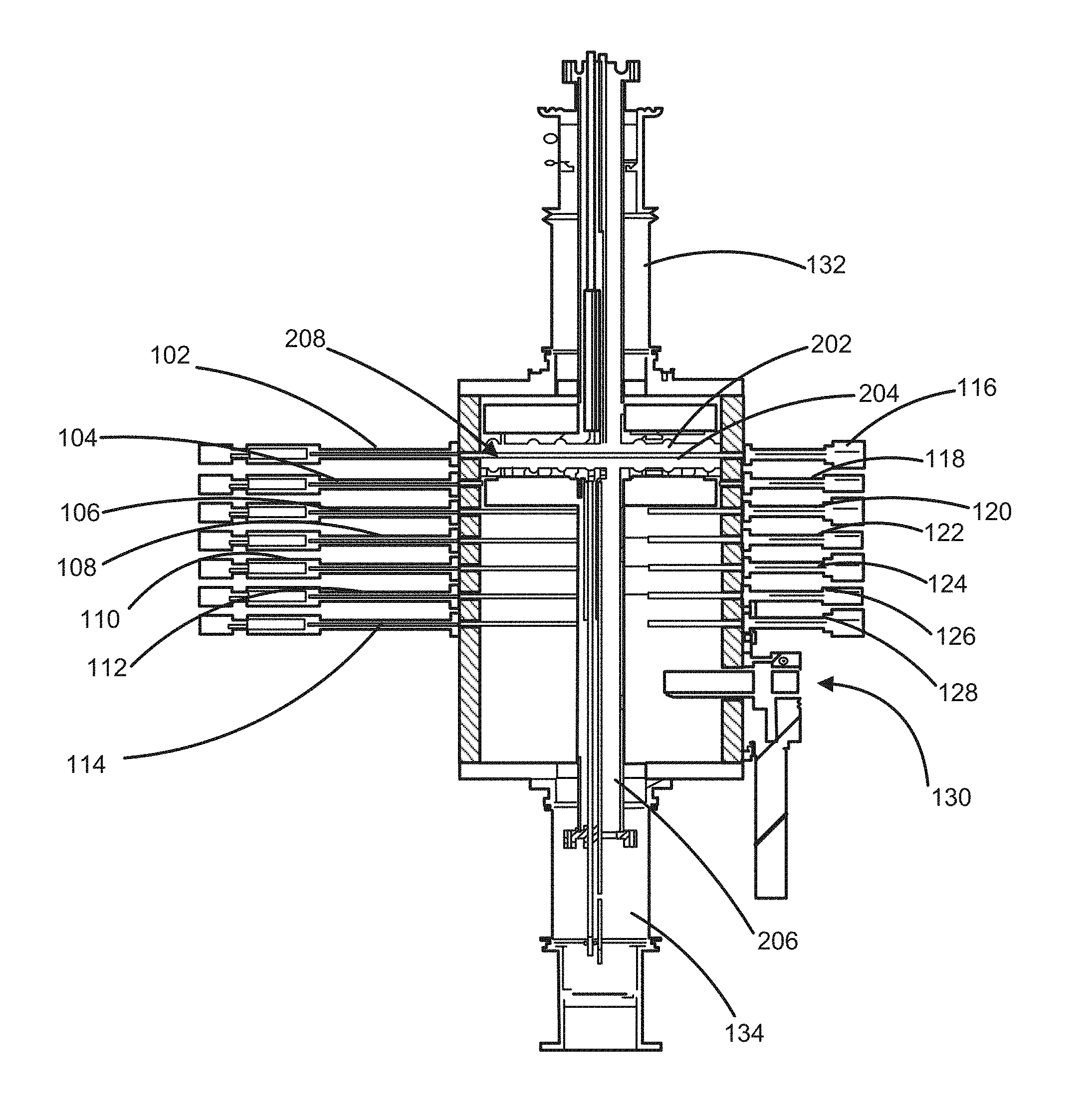
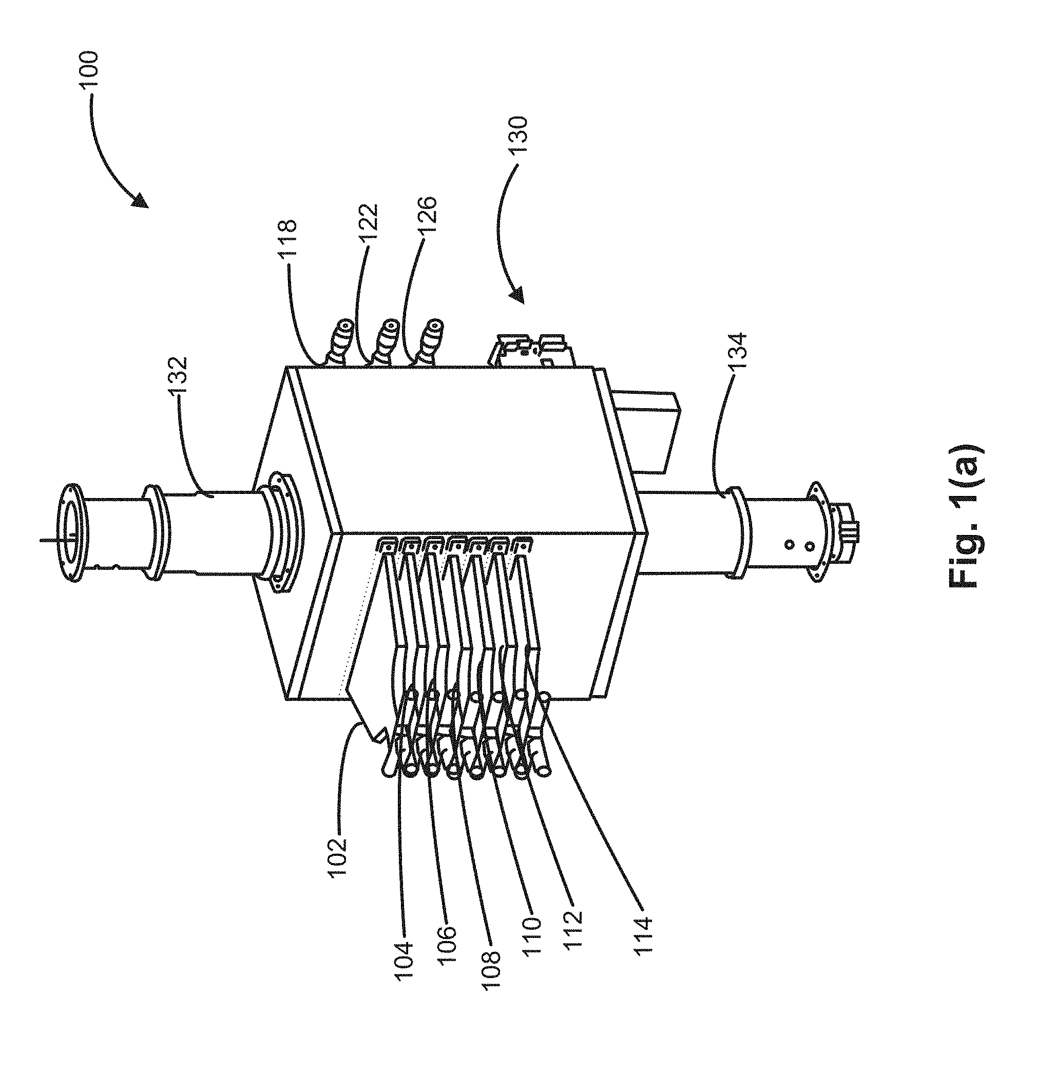
[0040] FIGS. 1(a) and 1(b) illustrate an exterior and FIGS. 2(a) to 3(d) illustrate additional views of a multi-zone gas-phase reactor 100 in accordance with exemplary embodiments of the disclosure. Multi-zone gas-phase reactor 100 includes one or more gas inlets, which in the illustrated example, include diffusers 102-114, one or more exhaust outlets, illustrated as collectors 116-128, a gate valve 130 for loading and unloading substrates, a top plate 202, a susceptor assembly 206, including a susceptor or plate 204, and conduits 132, 134 for, e.g., providing electrical and/or gas lines to portions of multi-zone gas-phase reactor 100.
[0041] Multi-zone gas-phase reactor 100 is illustrated with seven vertically-stacked reaction zones, wherein each reaction zone includes a gas inlet and an exhaust outlet. Multi-zone gas-phase reactors in accordance with other examples of the disclosure can include any suitable number of reaction zones. By way of examples, multi-zone gas-phase reactors can include 2-20, 2-15, 2-13, or 2-11 reaction zones. Further, although each reaction zone is illustrated with a gas inlet and a gas outlet, in some cases, the reaction zone may only include a gas outlet or a gas inlet. A height of a reaction zone can vary according to desired reactions. By way of some examples, e.g., in the case of ALD or ALE processing, a height of a reaction zone can be from about 0.1 mm to about 20, about 0.2 mm to about 10 mm, about 0.2 mm to about 0.5 mm, or be about 5 mm to about 10 mm. Flowrates, temperatures, and operating pressures within each reaction zone can also vary according to desired reactions and can include flowrates, pressures, and temperatures typically used for processing substrates. By way of examples, pressures can range from about 100 mtorr to about 50 torr, temperatures can range from about 100.degree. C. to about 700.degree. C., and flowrates (e.g., for purge gasses and/or precursor gasses) can range from about 10 sccm to about 10 slm.
[0042] A movable processing region 208 includes one or more reaction zones. In the illustrated example, processing region 208 includes a bottom surface of top plate 202 and an upper surface of susceptor assembly 206 (e.g., an upper surface of plate or susceptor 204). FIGS. 2(a) and 2(b) illustrate processing region 208 in an upper region of multi-zone gas-phase reactor 100. In this case, processing region 208 includes a gas inlet 209, an exhaust outlet 210, bottom surface 212 of plate 202 and top surface 214 of susceptor 204.
[0043] Top plate 202 (also referred to herein as movable plate) can include a solid or permeable plate. In accordance with some embodiments of the disclosure, top plate 202 includes a showerhead. In accordance with additional or alternative embodiments, top plate 202 can include part of a direct plasma system--e.g., top plate 202 can form all or part of an electrode of the direct plasma system. In accordance with various aspects of these embodiments, top plate 202 can be heated, be cooled, be at ambient temperature, and/or run under isothermal conditions. As best illustrated in FIGS. 2(b) and 3(b), multi-zone gas-phase reactor 100 can include a shield 216 coupled to top plate 202. Shield 216 helps isolate processing region 208 from other zones or regions within multi-zone gas-phase reactor 100. In accordance with other exemplary embodiments, a reactor, such as a multi-zone gas-phase reactor described herein can include guide 2802, 2812 and guide pads 2804 and/or guide bearings 2806 to guide shields 2808, 2810, as illustrated in FIG. 28.
[0044] Bottom plate 204 (also referred to herein as susceptor 204) can be heated, be cooled, be at ambient temperature, and/or run under isothermal conditions. Additionally or alternatively, bottom plate 204 can form part of a direct plasma system--e.g., bottom plate 202 can form all or part of an electrode of the plasma system. Multi-zone gas-phase reactor 100 can also include a shield 218 coupled to susceptor 204 to help isolate processing region 208 from other zones or regions within multi-zone gas-phase reactor 100.
[0045] Turning now to FIGS. 3(a) and 3(b), a portion of reactor 100 is illustrated with bottom plate 204 in a load/unload position. Top plate 202 can also be in a load/unload position to facilitate faster load/unload times. In this configuration, multi-zone gas-phase reactor 100 can receive a substrate or a substrate can be unloaded from multi-zone gas-phase reactor 100 from or to, for example, a wafer transfer station that may suitably be under vacuum conditions.
[0046] FIGS. 3(c) and 3(d) illustrate one exemplary technique to couple collectors (e.g., collectors 116-128) to an exterior of multi-zone gas-phase reactor 100. The same or similar technique can be used to couple diffusers 102-114 to an exterior of multi-zone gas-phase reactor 100. In the illustrated example, O-rings 302, 304 are used to form a seal between collector 128 and exterior 310 of multi-zone gas-phase reactor 100. Exterior 310 can include O-ring grooves 312, 314 to receive O-rings 302, 304. A space 303 between O-rings 302, 304 can be vacuum pumped to form a static seal.
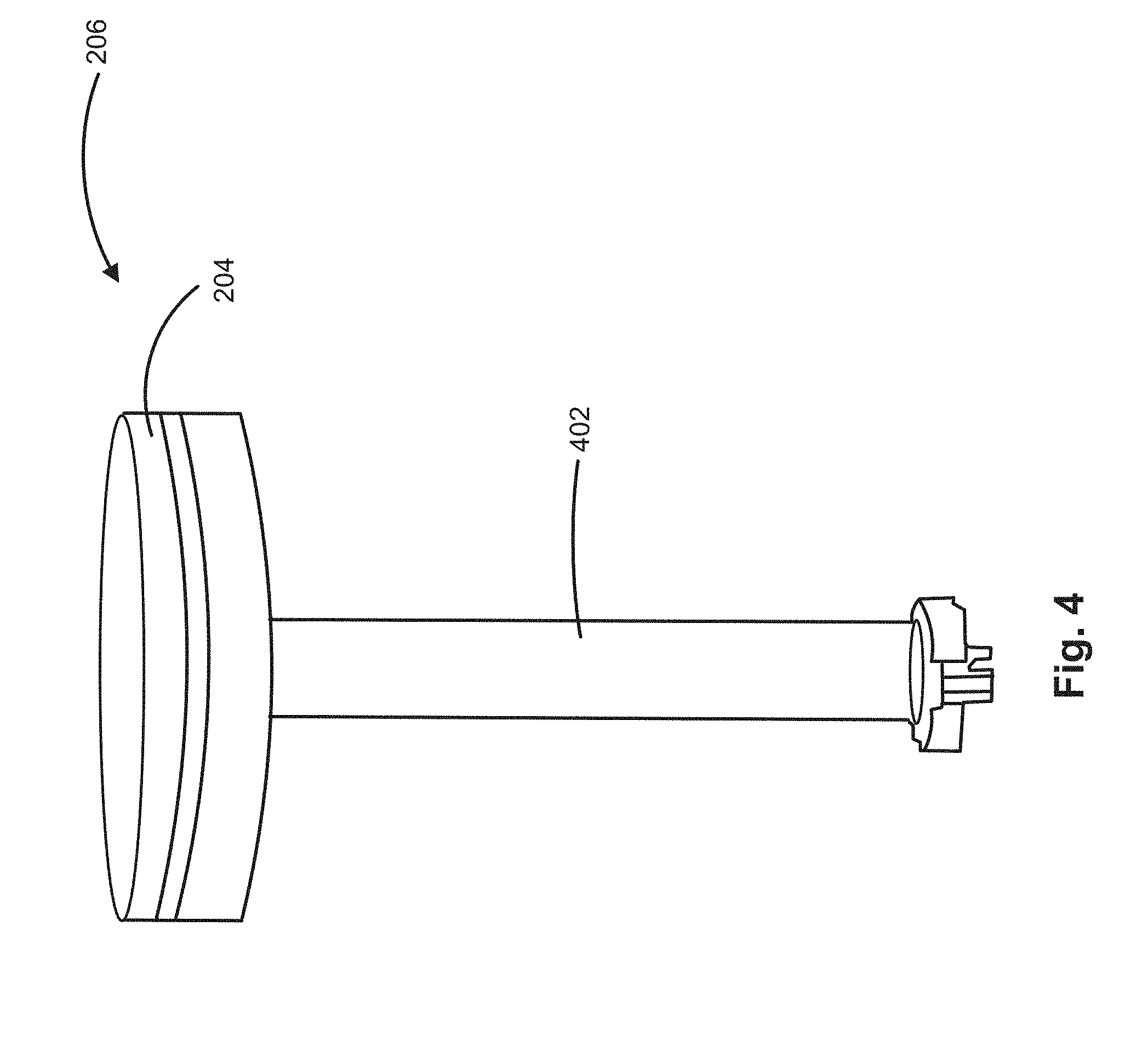
[0047] FIG. 4 illustrates susceptor assembly 206 in greater detail. Susceptor assembly 206 is designed to hold a substrate (e.g., a semiconductor wafer) in place during processing. Susceptor assembly 206 includes susceptor 204 and a member 402 mechanically coupled to susceptor 204. Member 402 can be a conduit through which heating and/or cooling lines are inserted. Further, member 402 and susceptor 204 can be rotatably coupled, such that subsector 204 can rotate (either continuously or indexed) during substrate processing and/or substrate loading or unloading.
[0048] FIGS. 5(a) to 5(c) illustrate a system 500 including a plurality of multi-zone gas-phase reactors 502, 504, and a substrate transfer station 506. For illustration purposes, system 500 is illustrated with two multi-zone gas-phase reactors 502, 504. However, systems in accordance with this disclosure can include any suitable number of multi-zone gas-phase reactors. For example, wafer transfer station 506 can couple to, for example, two, four, five, six, or eight multi-zone gas-phase reactors, and one or more substrate load/unload areas. Substrates can be simultaneously loaded into respective load/unload areas of multi-zone gas-phase reactors 502, 504 and/or other such reactors.
[0049] Multi-zone gas-phase reactors 502, 504 can be the same or similar to multi-zone gas-phase reactor 100 or any other multi-zone gas-phase reactors described herein. In the illustrated example, each multi-zone gas-phase reactor 502, 504 includes a plurality of diffusers. Multi-zone gas-phase reactor 502 includes diffusers 508-520 and multi-zone gas-phase reactor 504 includes diffusers 522-534. Similarly, each multi-zone gas-phase reactor 502, 504 includes a plurality of collectors. Collectors 536-548 of multi-zone gas-phase reactor 504 are illustrated in FIG. 5(b). Each reactor can also include a gate valve load area 550.
[0050] Similar to multi-zone gas-phase reactor 100, multi-zone gas-phase reactors 502, 504 include top plates 552, 554, which may be the same or similar to top plate 202, and bottom plates 556, 558, which may be the same or similar to susceptor 204. Top plates 552 and 554 can move in unison or independently from each other and/or their respective bottom plates/susceptors 556, 558.
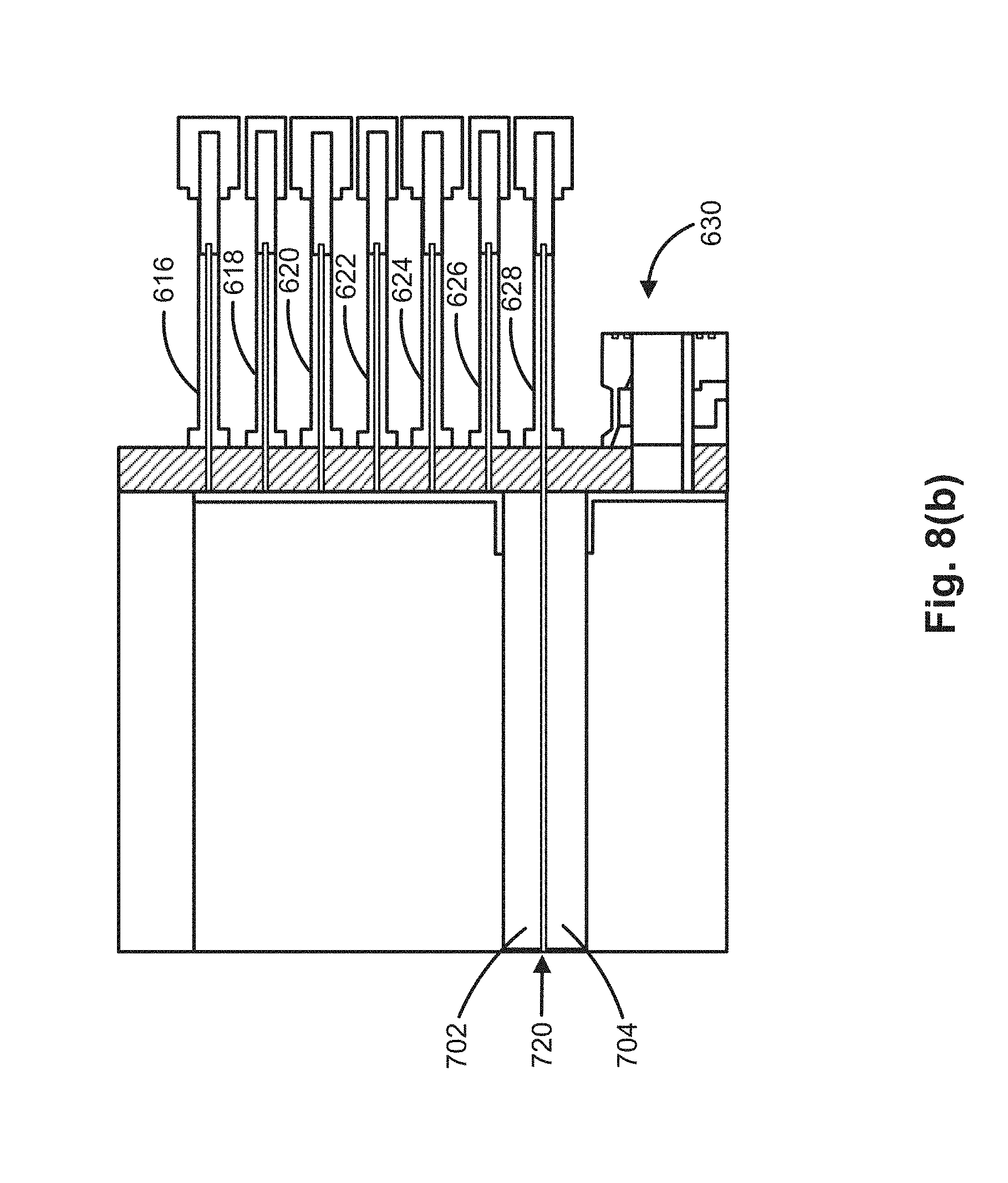
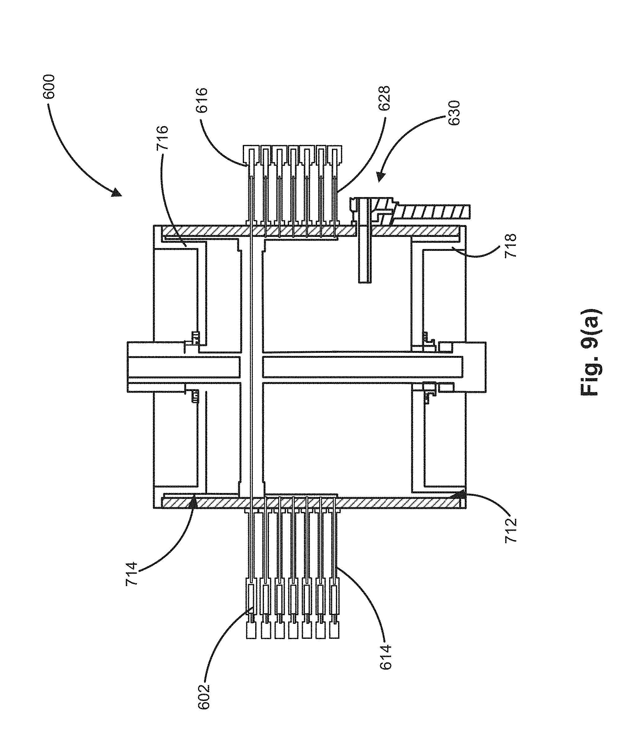
[0051] Turning now to FIGS. 6(a) to 9(b), a multi-zone gas-phase reactor 600 suitable for simultaneously processing a plurality of substrates is illustrated. Multi-zone gas-phase reactor 600 can be the same or similar to multi-zone gas-phase reactor 100, 502, or 504, although multi-zone gas-phase reactor 600 can be scaled to simultaneously process a plurality of substrates, such as 2, 3, 4, 5, 6, 7 or 8 substrates. Multi-zone gas-phase reactor 600 can be a stand-alone reactor or part of a system, such as system 500. Reactor 600 includes a load/unload area 630, which is configured to allow loading/unloading of substrates into or out of reactor 600.
[0052] Similar to the reactors described above, multi-zone gas-phase reactor 600 includes a plurality of diffusers 602-614 and a plurality of collectors 616-628. Diffusers 602-614 and collectors 616-628 can be the same or similar to other diffusers and collectors described herein; however, diffusers 602-614 and collectors 616-628 are scaled to simultaneously process multiple substrates within a processing region.
[0053] Multi-zone gas-phase reactor 600 includes a top plate 702 having a shield 706 associated therewith and a bottom plate/susceptor 704 having a shield 708 associated therewith. Associated shields 706, 708 move with and can be coupled to respective plates 702, 704 to help isolate a processing region 720. For example, if multi-zone gas-phase reactor 600 includes n reaction zones, shields 706, 708 extend over n-1, n-2, n-3, n-4, or the like reaction zones. In the illustrated example, shields 706, 708 extend over n-1 zones.
[0054] Multi-zone gas-phase reactor 600 includes recesses 712, 714 to receive shields 706, 708. Recesses 712, 714 extend to allow plates to a bottom position (e.g., a load/unload position) and a top position (e.g., to serve as a top plate in or above a top reaction zone within reactor 600). Multi-zone gas-phase reactor 600 also includes inserts 716, 718. Inserts 716, 718 can form part of recesses 712, 714. Inserts 716, 718 reduce an interior volume of reactor 600, while allowing use of shield 706, 708. Reducing reactor 600 interior volume is beneficial, because pump-down times to obtain desired vacuum conditions can be reduced.
[0055] FIGS. 7, 9(a) and 9(b) illustrate processing region 720 in a top reaction zone. FIGS. 8(a) and 8(b) illustrate processing region 720 in a bottom reaction zone.
[0056] FIGS. 10 and 11 illustrate a susceptor assembly 1100, including susceptor 704, for processing a plurality of substrates. Susceptor assembly 1100 can be the same or similar to susceptor assembly 206, except a susceptor assembly 1100 includes a susceptor 704 that has a top surface 1002, which can hold two or more substrates in place during processing. Susceptor assembly 1100 also includes a member 1102 mechanically coupled to susceptor 1004. Member 1102 can include a conduit through which heating and or cooling lines are inserted or be a solid member. Member 1102 and susceptor 704 can be rotatably coupled together, such that subsector 704 can rotate during substrate processing and/or loading and unloading.
[0057] FIGS. 12(a) to 13(b) illustrate another multi-zone gas-phase reactor 1200. Multi-zone gas-phase reactor 1200 is similar to multi-zone gas-phase reactors 100, 502, 504, 600, except multi-zone gas-phase reactor 1200 is illustrated with 11 reaction zones, each reaction zone including a diffuser (e.g., one of diffusers 1202-1224) and a collector (e.g., one of corresponding collectors 1226-1246). Similar to the multi-zone gas-phase reactors described above, multi-zone gas-phase reactor 1200 includes top plate 1302, bottom plate 1304, shields 1306, 1308, and a load/unload area 1248. In the illustrated case, shields 1306, 1308 extend over at least one adjacent reaction zone.
[0058] Turning now to FIGS. 14 and 15, exemplary integrated gate valve (IGV) assemblies 1400 and 1500 are schematically illustrated. As noted above, IGV assemblies can be used to isolate a processing region or reaction zone from other reaction zones and/or other regions within a reactor. IGV assemblies can be coupled to an inlet of a diffuser, such as any of the diffusers described herein. Generally, exemplary IGV assemblies as described herein provide desired isolation between reaction zones or regions via selection of pump and/or back suction conductance and/or pump speeds.
[0059] IGV assembly 1400 includes inlet precursor valve 1402, exhaust precursor valve 1404 (e.g., a back suction valve connected to an exhaust source), and inert gas inlets 1408 and 1410. As illustrated, inert gas inlets 1408, 1410 can provide inert gas (e.g., nitrogen, argon, or the like) in a direction toward a reaction zone inlet 1412 and toward exhaust valves 1414, 1416, which can suitably include back suction valves. This facilitates purging of a precursor line 1418 and mitigates mixing with other precursor lines 1420, 1422. As illustrated, assembly 1400 can include additional inert gas inlets 1424, 1426 for precursor lines 1420 and 1422, respectively.
[0060] IGV assembly 1500 includes a precursor inlet valve, inert gas valves 1504-1510, and exhaust valve 1512. During operation of IGV assembly 1500, when a precursor is introduced to a reaction zone inlet 1514, precursor valve 1502 and inert gas valves 1504, 1508 (e.g., low-flow valves) are on to provide an additional barrier to nearby reaction zones and the like. To purge a precursor line 1516, valves 1506 and 1510 can be opened to provide additional inert gas flow. In accordance with some aspects of these embodiments, valves 1502 and 1512 can be left on or open during processing, because the primary exhaust for a reaction zone can be the highest conductance and thus when a shield (e.g., shield 1306 or the like) does not block a precursor from entering a reaction zone, the precursor flows across a substrate and a small amount of the precursor will flow to an exhaust (e.g., through valve 1512). When an inlet is blocked--e.g., by a shield, a gas flow resistance is high enough, so that all or most of the precursor, along with purge gases from above and/or below, will flow directly to the exhaust and not to a reaction chamber.
[0061] FIGS. 26 and 27 illustrate additional exemplary reactors that include a gas curtain to facilitate isolation of a reaction zone or processing region from other zones or regions of a reactor. Reactor 2600 includes precursor inlets 2602, 2604 (which correspond to different reaction regions), inert gas inlets 2606-2612, a movable plate 2614, and a susceptor 2616, which can be part of a susceptor assembly. During operation of reactor 2600, inert gas flows as indicated by the respective arrows to provide a gas curtain. The inert gas flows from inlets 2606-2612 toward an exhaust 2618.
[0062] Reactor 2700 includes inert gas inlets 2702, 2704. In the illustrated example, an inert gas enters gas inlet 2702, runs through a conduit 2706 coupled to a movable plate 2708, and continues to flow between a sidewall 2712 and a shield 2710 to an exhaust 2714. Similarly, an inert gas (which can be the same or similar to the inert gas in conduit 2706) flows from inlet 2704 through a conduit 2716, which can be coupled to a susceptor 2718, and continues to flow between a sidewall 2720 and a shield 2722 to an exhaust 2724, which can be the same as exhaust 2714. The inert gas flow, as illustrated by the arrows, provides a gas curtain to facilitate isolation between reaction zones and/or regions.
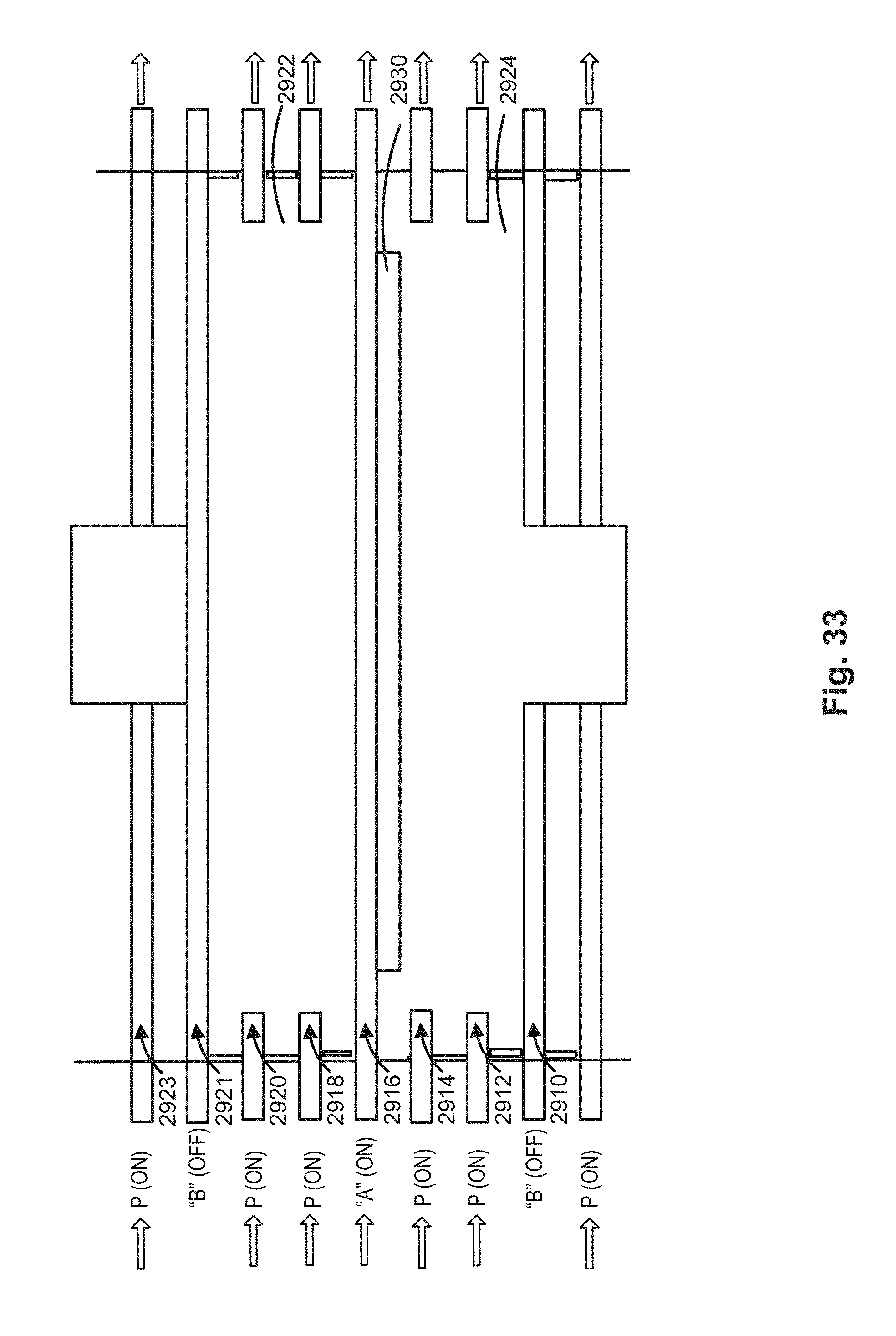
[0063] FIGS. 29-33 illustrate another technique for isolating precursors in nearby reactions zones. In the illustrated example, a reactor 2900 includes a plurality of reaction zones 2902-2920, 2921, and 2923. Similar to other reactors described herein, reactor 2900 includes a top plate 2922, a bottom plate 2924, and shields 2926, 2928. Although illustrated with a precursor reaction zone surrounded on each side by two precursor reaction zones, exemplary reactors are not so limited. Other reactors can include one or more purge reaction zones adjacent a precursor reaction zone.
[0064] Reaction zones 2904, 2910, and 2916 can be used to expose a substrate to a precursor--e.g., a precursor used in CVD processing, such as an ALD or ALE process. One or more (e.g., two) purge reaction zones 2902, 2906, 2908, 2912, 2914, 2918, 2920 are adjacent each precursor reaction zone 2904, 2910, and 2916. Using one or more purge reaction zones 2902, 2906, 2908, 2912, 2914, 2918, 2920 adjacent precursor reaction zones 2904, 2910, and 2916 provides isolation of one or more precursors from other precursors used in nearby reaction zones. It is generally desirable to have separation of the gasses, and particularly of the precursors to prevent undesirable mixing of the gases. Mixing of the precursors, for example in one or more purge reaction zones 2902, 2906, 2908, 2912, 2914, 2918, 2920, may cause particles to form in those regions.
[0065] Some purge gas from purge reaction zones 2902, 2906, 2908, 2912, 2914, 2918, 2920 may leak into nearby precursor reaction precursor reaction zones 2904, 2910, and 2916. Generally, there is a tendency for more purge gas to leak into a precursor reaction zone 2904, 2910, and/or 2916, where the purge gas pressure is highest--e.g., near an inlet of the purge gas. To increase gas (e.g., precursor separation), purge gas (e.g., in purge reaction zones 2902, 2906, 2908, 2912, 2914, 2918, 2920) can be introduced at an angle offset from the angle of introduction of the precursor gasses. For example, the inlets and corresponding outlets for the precursor gasses and the inlets and corresponding outlets for the purge gasses can be offset by 30, 45, 60, 90, 120, 135, 180, or any combination of such degrees or other degrees. Introducing the purge gasses from another direction may increase dilution of a precursor within a precursor reaction zone 2904, 2910, and/or 2916, but generally reduces potential of undesired mixing of the precursors. To provide additional isolation, precursors not in use in a reaction zone can be turned off.
[0066] By way of example, with reference to FIG. 29, a substrate 2930 is exposed to a first precursor "B" in reaction zone 2910. In this case, precursor "A" is turned off (e.g., a valve is closed), and purge lines to purge reaction zones 2902, 2906, 2908, 2912, 2914, 2918, 2920 are on. Alternatively, purge lines to one or more adjacent purge reaction zones are on and other purge lines can be off.
[0067] With reference to FIG. 30, as top plate 2922 and bottom plate 2924 move upward, shield 2928 and purge gas from zones 2912, 2914, 2906, and 2906 block precursor "B" from entering nearby reaction zone 2904 and/or 2916.
[0068] As substrate 2930 continues to move upward in reactor 2900, substrate 2930 is exposed to a first purge in reaction zone 2912, as illustrated in FIG. 31. In this case, adjacent precursors "A" and "B" can be turned off, as shown. Substrate 2930 can then be exposed to a second purge in reaction zone 2914, as illustrated in FIG. 32.
[0069] Substrate 2930 can then be exposed to precursor "A" in reaction zone 2916, while precursor "B" is off, as illustrated in FIG. 33. Purge reaction zones 2918, 2920 and 2912, 2914 provide additional isolation to, for example, reaction zones 2910 and 2921.
[0070] During substrate processing, top plate 2922 and bottom plate 2924 can move continuously through reactor 2900 from a load/unload area though the reaction zones 2902-2923. An acceleration of the plates (without a vacuum chuck) can be about 0.67 g. By way of particular example, a unit cell can be defined as a purge reaction zone, a first precursor reaction zone, two adjacent purge reaction zones, a second precursor reaction zone, and another purge zone can be about 80 mm in height. In this case, a time to travel through a unit cell can be about 280 ms. With a vacuum chuck and 3 g acceleration, the travel time could be reduced to about 130 ms. If top plate 2922 and bottom plate 2924 move in an indexed fashion, the time to traverse a unit cell would generally increase.
[0071] Turning now to FIGS. 16-22, an exemplary method of using a multi-zone gas-phase reactor is illustrated. The method is conveniently illustrated using a reactor 1600, which includes a movable susceptor assembly 1602, a movable plate 1604, a gate valve opening 1606, and reaction zones 1702, 1802, 1902, 2002, and 2102. Although not illustrated in FIGS. 16-22, reactor 1600 can include shields and/or IGV assemblies as described and illustrated elsewhere.
[0072] During operation of reactor 1600, a substrate 1608 is loaded onto a top surface 1610 of a susceptor 1612. As illustrated, substrate 1608 can be loaded onto and/or removed from susceptor 1612 using lift pins 1614, 1616, which go through at least a portion of susceptor 1612. Once substrate 1608 is loaded onto susceptor 1612, gate valve 1606 is closed.
[0073] Substrate 1608 can be moved to a processing region including reaction zone 1702 by moving susceptor assembly 1602 and movable plate 1604 to reaction zone 1702 positions. As noted above, susceptor assembly 1602 and movable plate 1604 can move together or move independently to positions for various reaction zones, processing regions, and load/unload positions.
[0074] A processing region including reaction zone 1702 can be used for various processes, including cleaning or treatment of a substrate surface. For example, hydrogen gas and/or ammonia gas can be used to treat a surface of a substrate in a processing region including reaction zone 1702. Reactant can enter from an inlet 1704 and/or from top plate 1604. The reactant can include activated species and/or can be exposed to a plasma process.
[0075] Next, substrate 1608 is moved to a processing region including reaction zone 1802. As illustrated, susceptor assembly 1602 can rotate during processing in a processing region including reaction zone 1802 (or anywhere in reactor 1600, including the loading/unloading zone). By way of example, a first precursor for an ALD deposition process can be introduced at an inlet 1804. At a processing region including a reaction zone 1902, a second precursor can be introduced at inlet 1904. First and second precursors can be used for, for example, ALD or ALE processing.
[0076] At a processing region including a reaction zone 2002, substrate 1608 is exposed to the first precursor (or another precursor). As illustrated, the precursor can be introduced at an opposite side of reactor 1600. Introducing reactants or other gases at various locations for various reaction zones can facilitate uniform gas-phase processes, such as deposition, etch, clean, and treatment processes. Introducing reactants at various locations can also facilitate reactor design (e.g., reactors having less volume). As noted above, inlets and/or outlets of a reactor can be offset by, for example, 30, 45, 60, 90, 120, 135, or 180 degrees.
[0077] Substrate 1608 is exposed to another precursor from gas inlet 2104 in a processing region including reaction zone 2102. The precursor can be the same or different from the precursor used in reaction zone 1902.
[0078] Substrate 1608 can suitably be moved between reaction zones 1702-2102 a desired number of times--for example, until a desired amount of material is deposited or removed. Susceptor assembly 1602 can then be lowered to a load/unload position 1620, illustrated in FIG. 16.
[0079] FIG. 22 illustrates susceptor 1612 in a low position (e.g., a load/unload position) and movable plate 1604 in a high position (e.g., reaction zone 1702 position or above). When movable plate 1604 and susceptor 1612 are in these positions, a processing region 2202, including reaction zones 1702-2102 can be cleaned or treated. For example, region 2202 can be exposed to a direct and/or remote plasma clean or treatment process. Although region 2202 is illustrated as encompassing reaction zones 1702-2102, susceptor 1612 and movable plate 1604, a processing region can encompass any of one or more reaction zones 1702-2102 during such processing. Similarly, movable plates and susceptors of other reactors described herein can be moved to similar locations to create such processing regions.
[0080] Another feature of exemplary multi-zone gas-phase reactors as described herein is the ability to apply an alumina or similar coating to areas of the reactor--e.g., to one or more reaction zones (e.g., zones 1702-2102 or any subset thereof). The alumina can serve as a barrier layer to the reactor surfaces for minimizing potential metallic contamination. The alumina coat can also be used to cap any undesirable film formation on the reactor walls in order to improve reactor lifetime. The alumina coat can also improve the ability to clean and refurbish the reactor.
[0081] FIGS. 23-25 illustrate additional exemplary configurations of exemplary reactors in accordance with this disclosure. FIG. 23 illustrates a multi-zone gas-phase reactor 2300 including seven reaction zones 2302-2314 and a load/unload zone 2330.
[0082] During operation of multi-zone gas-phase reactor 2300, a substrate 2316 is loaded onto a susceptor 2318 of a susceptor assembly 2320 via a gas valve opening 2322. Substrate 2316 can be moved to various processing regions including one or more reaction zones 2302-2314, by moving susceptor assembly 2320 and a movable plate 2324. In the illustrated example, substrate 2316 is exposed to a first precursor in a processing region including reaction zone 2302, a purge gas in a processing region including reaction zone 2304, a second precursor in a processing region including reaction zone 2306, a purge gas in a processing region including reaction zone 2308, the first precursor in a processing region including reaction zone 2310, a purge gas in a processing region including reaction zone 2312, and the second precursor in a processing region including reaction zone 2314. Substrate 2316 can be moved between processing regions including reaction zones 2302-2314 a desired number of times--e.g., until a desired amount of material is deposited or removed from a surface of substrate 2316.
[0083] FIG. 24 illustrates another exemplary reactor configuration. Multi-zone gas-phase reactor 2400 includes reaction zones 2402-2410. In the illustrated example, a reaction processing region 2430 includes two reaction zones 2408, 2410 between a movable plate 2412 and a susceptor 2414. In this case, a first gas and a second gas can be introduced between a bottom surface 2420 of movable plate 2412 and a top surface 2422 of a susceptor 2414. The first and second gases 2416, 2418 can be introduced simultaneously or sequentially. For example, first and second precursor gases can be introduced simultaneously during a CVD process. One or more of the first and second gases can include an inert gas. Although illustrated with two gas inlets, reaction zones and/or processing regions of multi-zone gas-phase reactors as described herein can include any suitable number of gas inlets, for reactants, carrier, and/or purge gases.
[0084] Reactor 2500 is illustrated with one reaction zone 2502, a movable plate 2504, which includes a showerhead gas distribution apparatus 2506, a susceptor assembly 2508, and a load/unload zone 2510. Movable plate and/or movable susceptor assembly 2808 allows for variable gap control of reaction zone 2502. Gas distribution apparatus 2506 can form part of a direct plasma system. In the illustrated example, reactor 2500 allows for both cross flow and vertical flow of gases. This provides an alternate means of keeping precursors separated to avoid mixing and resulting particle generation. A precursor with the highest desirable degree of flux uniformity can be distributed through showerhead gas distribution apparatus 2506, while another precursor can be delivered via the cross-flow path.
[0085] Although illustrated with one reaction zone 2502, reactors in accordance with other exemplary embodiments can include a showerhead gas distribution apparatus and any suitable number of reaction zones.
[0086] Although exemplary embodiments of the present disclosure are set forth herein, it should be appreciated that the disclosure is not so limited. For example, although the reactors, reactor systems, and methods are described in connection with various specific configurations, the disclosure is not necessarily limited to these examples. Indeed, unless otherwise noted, features and components of various reactors and systems described herein can be interchanged. Various modifications, variations, and enhancements of the reactors, systems, and methods set forth herein may be made without departing from the spirit and scope of the present disclosure.
[0087] The subject matter of the present disclosure includes all novel and nonobvious combinations and subcombinations of the various systems, assemblies, reactors, components, and configurations, and other features, functions, acts, and/or properties disclosed herein, as well as any and all equivalents thereof.
* * * * *
D00000
D00001
D00002
D00003
D00004
D00005
D00006
D00007
D00008
D00009
D00010
D00011
D00012

D00013

D00014

D00015

D00016

D00017
D00018
D00019

D00020

D00021

D00022

D00023

D00024

D00025

D00026

D00027

D00028

D00029

D00030

D00031

D00032

D00033

D00034

D00035

D00036

D00037

D00038

D00039

D00040

D00041

D00042

D00043

D00044

D00045
XML
uspto.report is an independent third-party trademark research tool that is not affiliated, endorsed, or sponsored by the United States Patent and Trademark Office (USPTO) or any other governmental organization. The information provided by uspto.report is based on publicly available data at the time of writing and is intended for informational purposes only.
While we strive to provide accurate and up-to-date information, we do not guarantee the accuracy, completeness, reliability, or suitability of the information displayed on this site. The use of this site is at your own risk. Any reliance you place on such information is therefore strictly at your own risk.
All official trademark data, including owner information, should be verified by visiting the official USPTO website at www.uspto.gov. This site is not intended to replace professional legal advice and should not be used as a substitute for consulting with a legal professional who is knowledgeable about trademark law.