Integrated System And Method For Source/drain Engineering
YAN; Chun ; et al.
U.S. patent application number 16/148430 was filed with the patent office on 2019-01-31 for integrated system and method for source/drain engineering. The applicant listed for this patent is Applied Materials, Inc.. Invention is credited to Xinyu BAO, Schubert S. CHU, Hua CHUNG, Melitta Manyin HON, Chun YAN.
| Application Number | 20190035623 16/148430 |
| Document ID | / |
| Family ID | 61618753 |
| Filed Date | 2019-01-31 |
| United States Patent Application | 20190035623 |
| Kind Code | A1 |
| YAN; Chun ; et al. | January 31, 2019 |
INTEGRATED SYSTEM AND METHOD FOR SOURCE/DRAIN ENGINEERING
Abstract
Implementations described herein generally provide a method of processing a substrate. Specifically, the methods described are used for cleaning and etching source/drain regions on a silicon substrate in preparation for precise Group IV source/drain growth in semiconductor devices. Benefits of this disclosure include precise fin size control in devices, such as 10 nm FinFET devices, and increased overall device yield. The method of integrated clean and recess includes establishing a low pressure processing environment in the processing volume, and maintaining the low pressure processing environment while flowing a first gas over a substrate in a processing volume, depositing a salt on the substrate, heating the processing volume to greater than 90.degree. C., purging the processing volume with a second inert gas, and recessing a source/drain region disposed on the substrate.
| Inventors: | YAN; Chun; (San Jose, CA) ; BAO; Xinyu; (Fremont, CA) ; HON; Melitta Manyin; (San Jose, CA) ; CHUNG; Hua; (San Jose, CA) ; CHU; Schubert S.; (San Francisco, CA) | ||||||||||
| Applicant: |
|
||||||||||
|---|---|---|---|---|---|---|---|---|---|---|---|
| Family ID: | 61618753 | ||||||||||
| Appl. No.: | 16/148430 | ||||||||||
| Filed: | October 1, 2018 |
Related U.S. Patent Documents
| Application Number | Filing Date | Patent Number | ||
|---|---|---|---|---|
| 15890117 | Feb 6, 2018 | 10090147 | ||
| 16148430 | ||||
| 15417496 | Jan 27, 2017 | |||
| 15890117 | ||||
| 62423082 | Nov 16, 2016 | |||
| 62395765 | Sep 16, 2016 | |||
| Current U.S. Class: | 1/1 |
| Current CPC Class: | H01L 29/66795 20130101; H01L 29/66636 20130101; H01L 21/02057 20130101 |
| International Class: | H01L 21/02 20060101 H01L021/02; H01L 29/66 20060101 H01L029/66 |
Claims
1. A method of processing a workpiece, comprising: flowing a first gas mixture into a processing chamber; forming a first plasma from the first gas mixture; exposing the workpiece to the first plasma, wherein the workpiece comprises: a substrate comprising a source/drain region; and a fin layer extending from a surface of the source/drain region; and depositing a salt on one or more surfaces of the source/drain region and the fin layer.
2. The method of claim 1, wherein the first gas mixture comprises NH.sub.3 and NF.sub.3.
3. The method of claim 1, wherein source/drain region is disposed between a plurality of dielectric material features.
4. The method of claim 1, further comprising: flowing a second gas mixture into the processing chamber before flowing the first gas mixture, the second gas mixture comprising hydrogen gas and argon gas; forming a second plasma of the second gas mixture; and exposing the workpiece to the second plasma before exposing the workpiece to the first plasma.
5. The method of claim 1, wherein the fin layer comprises silicon.
6. The method of claim 1, further comprising: heating the workpiece to about 90.degree. C. or more; and purging the processing chamber of the first gas mixture by flowing a purge gas mixture thereinto.
7. The method of claim 6, wherein heating the workpiece to about 90.degree. C. or more removes the salt or reaction byproducts of the salt from the one or more surfaces of the source/drain region and the fin layer.
8. The method of claim 7, wherein depositing the salt and removing the salt or reaction byproducts of the salt cleans one or both of a native oxide or contaminates disposed on the one or more surfaces of the source/drain region and the fin layer.
9. The method of claim 8, wherein the workpiece further comprises a dielectric material layer disposed on the fin layer.
10. The method of claim 9, wherein the dielectric material layer is a dummy gate.
11. The method of claim 6, further comprising: flowing an etchant gas mixture into the processing chamber; forming an etching plasma from the etchant gas mixture; and exposing the workpiece to the etching plasma to reduce a width of the fin layer.
12. The method of claim 11, wherein exposing the workpiece to the etching plasma reduces the width of the fin layer by up to about 2 nm.
13. The method of claim 11, wherein the etchant gas mixture comprises chlorine.
14. The method of claim 1, further comprising: depositing an Si:As layer on one or more surfaces of the source/drain region.
15. The method of claim 14, further comprising: depositing an Si:P layer on one or more surfaces of the source/drain region.
16. A method of processing a substrate, comprising: flowing a first processing gas mixture comprising NH.sub.3 and NF.sub.3 into a processing chamber; forming a first plasma from the first processing gas mixture; exposing the substrate to the first plasma, wherein the substrate comprises: a source/drain region disposed between a plurality of dielectric material features; and a fin layer extending from a surface of the source/drain region; depositing a salt on one or more surfaces of the source/drain region and the fin layer; and removing one or both of the salt or reaction byproducts of the salt from the one or more surfaces of the source/drain region and the fin layer, comprising: heating the substrate to 90.degree. C. or more; and purging the processing chamber of the first processing gas mixture by flowing a purging gas thereinto.
17. The method of claim 16, wherein depositing the salt on the one or more surfaces of the source/drain region and the fin layer and removing one or both of the salt or reaction byproducts of the salt and the one or more surfaces of the source/drain region and the fin layer includes removing a native oxide layer formed on the one or more surfaces of the source/drain region and the fin layer.
18. The method of claim 16, further comprising: flowing a second processing gas mixture comprising H.sub.2 and Cl.sub.2 into the processing chamber; forming a second plasma from the second processing gas mixture; and exposing the substrate to the second plasma.
19. The method of claim 18, wherein exposing the substrate to the second plasma removes a material thickness of up to about 2 nm from the one or more surfaces of the source/drain region and the fin layer.
20. The method of claim 19, further comprising: depositing an Si:P layer on one or more surfaces of the source/drain region.
21. The method of claim 5, wherein the fin layer further comprises at least one of germanium, carbon, boron, and phosphorous.
Description
CROSS-REFERENCE TO RELATED APPLICATIONS
[0001] This application is a continuation of U.S. patent application Ser. No. 15/890,117 filed on Feb. 6, 2018, which is a continuation of U.S. patent application Ser. No. 15/417,496, filed on Jan. 27, 2017, which claims priority to Provisional Patent Application Ser. No. 62/395,765, filed Sep. 16, 2016, and Provisional Patent Application Ser. No. 62/423,082, filed on Nov. 16, 2016, all of which are herein incorporated by reference.
BACKGROUND
Field
[0002] Implementations of the present disclosure generally relate to the manufacture of semiconductor devices. More specifically, implementations described herein relate to methods for source/drain engineering.
Description of the Related Art
[0003] Integrated circuits are formed in and on silicon and other semiconductor substrates. In the case of single crystal silicon, substrates are made by growing an ingot from a bath of molten silicon, and then sawing the solidified ingot into multiple substrates. An epitaxial silicon layer may then be formed on the monocrystalline silicon substrate to form a defect-free silicon layer that may be doped or undoped. Semiconductor devices, such as transistors, are manufactured from the epitaxial silicon layer. The electrical properties of the formed epitaxial silicon layer will generally be better than the properties of the monocrystalline silicon substrate.
[0004] Group IV elements may be advantageous in certain applications for forming silicon-based devices. For example, Group IV elements may serve as a source/drain region in sub-10 nm Fin Field Effect Transistor (FinFET) devices due to the low contact resistance, superior electron mobility and lower operation voltage. However, there are major challenges in preparing a substrate for Group IV source/drain growth. Surfaces of the monocrystalline silicon and the epitaxial silicon layer are susceptible to contamination when exposed to typical fabrication facility ambient conditions, and there might be a few atomic layers of damaged Si from previous process steps. For example, a native oxide layer may form on the monocrystalline silicon surface prior to deposition of the epitaxial layer. Additionally, contaminants present in the ambient environment may deposit on the monocrystalline surface and may come from previous process steps. The presence of a native oxide layer or contaminants on the monocrystalline silicon surface negatively affects the quality of an epitaxial layer subsequently formed on the monocrystalline surface. While present cleaning methods remove some of the native oxides and contaminants from the monocrystalline silicon surface, some contaminants may still remain.
[0005] Therefore, there is a need for a method for integrated cleaning a substrate surface and subsequent recessing prior to performing an epitaxial deposition process.
SUMMARY
[0006] Implementations described herein generally provide a method of processing a workpiece. The method of processing the workpiece includes disposing the workpiece in a processing volume. The workpiece includes a substrate. The substrate includes a source/drain region disposed on the substrate. The method of disposing a workpiece also includes establishing a low pressure processing environment in the processing volume. The method of disposing a workpiece also includes maintaining the low pressure processing environment while delivering a first gas containing to the processing volume, depositing a salt on the workpiece, heating the substrate to greater than 90.degree. C., purging the processing volume with a second inert gas, and recessing the source/drain regions.
BRIEF DESCRIPTION OF THE DRAWINGS
[0007] So that the manner in which the above recited features of the present disclosure can be understood in detail, a more particular description of the disclosure, briefly summarized above, may be had by reference to implementations, some of which are illustrated in the appended drawings. It is to be noted, however, that the appended drawings illustrate only exemplary implementations and are therefore not to be considered limiting of its scope, for the disclosure may admit to other equally effective implementations.
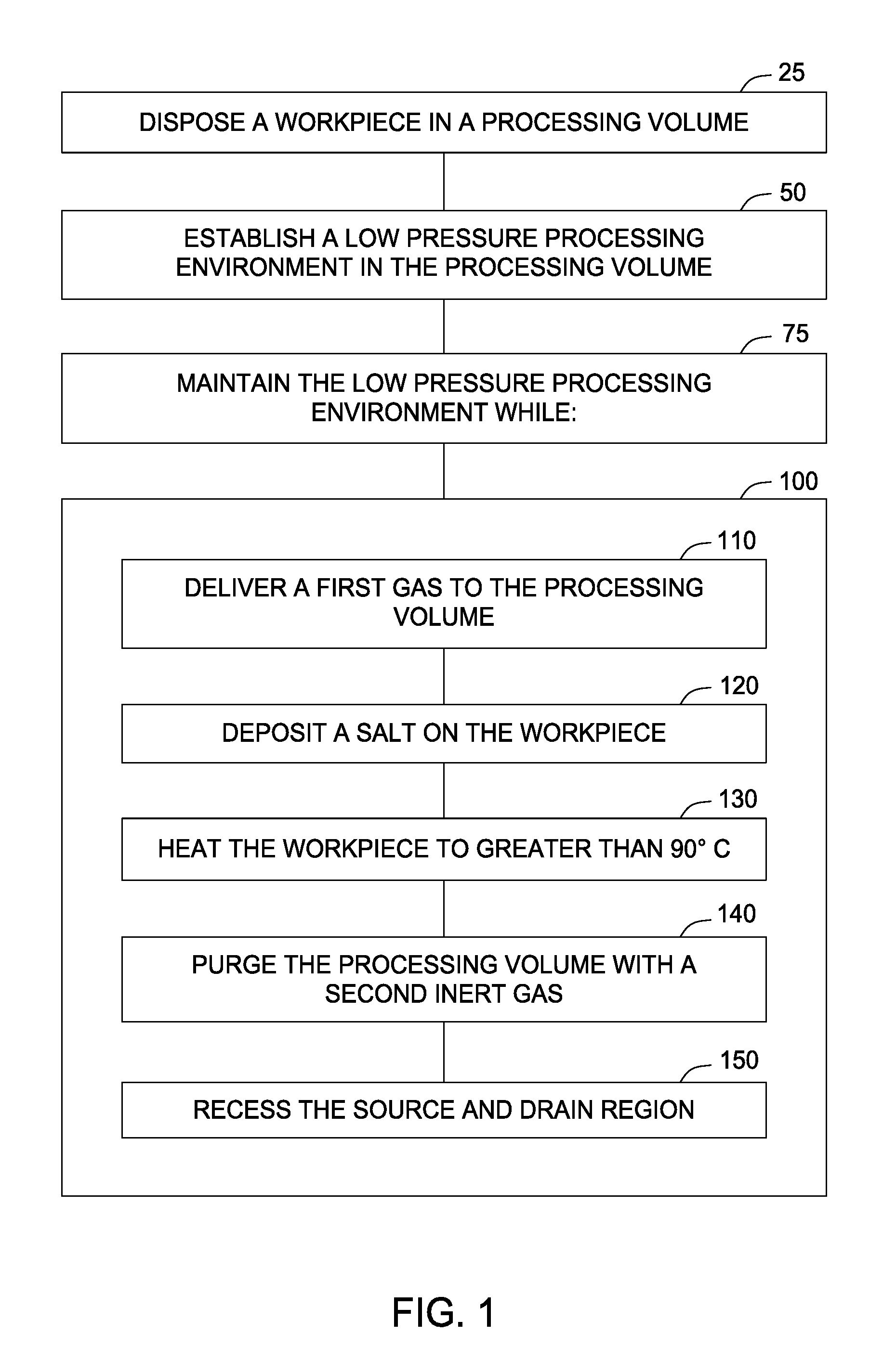
[0008] FIG. 1 is a flow diagram illustrating operations of a method according to one implementation described herein.
[0009] FIGS. 2A-2C illustrate a schematic, cross-sectional view of a device structure depicting stages of fabrication in accordance with the method of FIG. 1.
[0010] To facilitate understanding, identical reference numerals have been used, where possible, to designate identical elements that are common to the figures. It is contemplated that elements and features of one implementation may be beneficially incorporated in other implementations without further recitation.
DETAILED DESCRIPTION
[0011] Implementations of the present disclosure generally relate to methods for forming semiconductor devices. More specifically, methods are described for sub-10 nm cleaning and recessing substrates in preparation for precise Group IV source/drain growth in FinFET devices.
[0012] FIG. 1 is a flow diagram illustrating a method 100 for cleaning and recessing substrates in preparation for precise source/drain deposition comprising Group IV elements on a silicon substrate. FIGS. 2A-2C depict stages of fabrication of a device structure in accordance with the method 100 of FIG. 1. The method 100 is described below in accordance with operations of cleaning and recessing a substrate as illustrated in FIGS. 2A-2C.
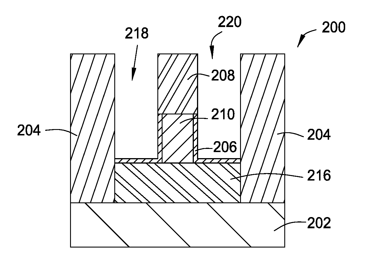
[0013] As illustrated in FIG. 1, a workpiece, including a substrate 202 with a device 200 that has a source/drain region formed on the substrate, is disposed in a processing volume at step 25. For example, the device may have sub-10 nm trenches 218, 220. The processing volume may be contained within a processing chamber. The workpiece is shown in FIG. 2, and may be pre-cleaned prior to performing the method 100. The pre-cleaning may include any conventional wet or dry cleaning method.
[0014] As shown in FIG. 2A, the workpiece has a device 200 that includes a dielectric material 204 disposed on a substrate 202, a pre source/drain region 216, a fin layer 210 disposed on the pre source/drain region 216, a dummy gate 208, and contaminants 206. In one implementation, the pre source/drain region 216 may be disposed on the substrate 202 and within the dielectric material 204. The dummy gate 208 may be disposed on the fin layer 210. The contaminants 206 may be disposed on the pre source/drain region 216 and the fin layer 210. The substrate 202 may be a silicon-containing substrate. The substrate 202 may further comprise germanium (Ge), carbon (C), boron (B), phosphorous (P), or other materials that may be co-grown, doped and/or associated with silicon materials. The substrate 202 may be part of a device, such as a fin shaped field effect transistor (FinFET) device. In one implementation, the FinFET device may be sized for the 10 nm node.
[0015] The dielectric material 204, such as a shallow trench isolation (STI) oxide, may comprise one or more of silicon oxide (SiO), silicon dioxide (SiO.sub.2), silicon nitride (SiN), silicon oxynitride (SiON), or other suitable materials that may be used to form a dielectric material. The dielectric material 204 may be deposited by various deposition processes. For example, the dielectric material 204 may be deposited by a chemical vapor deposition (CVD) process, which may be plasma enhanced. The contaminants 206 may include native oxide and dangling silicon bonds saturated with hydrogen such as SiO.sub.2 or GeO.sub.2. The dummy gate 208 may comprise silicon nitride (SiN). The pre source/drain region 216 may comprise silicon and may further comprise germanium (Ge), carbon (C), boron (B), phosphorous (P), or other materials that may be co-grown, doped and/or associated with silicon materials.
[0016] The workpiece, including the device 200, may be placed in an inductively coupled plasma (ICP) plasma reactor chamber. Suitable chambers include the CENTRIS.RTM. or MESA.RTM. chamber available from Applied Materials, Inc. of Santa Clara, Calif. Chambers available from other manufacturers may also be used to practice implementations described herein. A low pressure processing environment may be established within the chamber at step 50 of FIG. 1. The low pressure processing environment may be maintained (at step 75 of FIG. 1) while each of the operations of method 100 proceed. At operation 110 of FIG. 1, a first gas may be delivered over the workpiece, including substrate 202 in the processing volume. The first gas may be a hydrogen argon (H.sub.2Ar) gas mixture. The first gas may be inert. In one implementation, the ion energy is controlled with low RF source power between 200-800 watts or plasma pulsing. The hydrogen gas may be flowed at a rate of between 10-500 sccm, and the argon may be flowed at a rate of between 300-1000 sccm. While the first gas is delivered, the pressure of the processing volume may be maintained between 5 mT to 50 mT. The temperature of the processing volume may be between 20.degree. C. and 40.degree. C., and the ion energy may be less than 50 electronvolt (eV). The first gas mixture producing the low energy ions may advantageously penetrate the native oxide contaminants 206 located within trenches 218, 220 to break silicon-oxygen bonds in preparation for subsequent removal and activate the sub-oxide (SiO) disposed underneath. In one implementation, the hydrogen ions or radicals within the first gas mixture react with the native oxide to form volatile hydroxides. The dry clean gas mixture may be able to penetrate the small sub-10 nm trenches and contaminants efficiently to provide for a higher throughput without damaging the device 200.
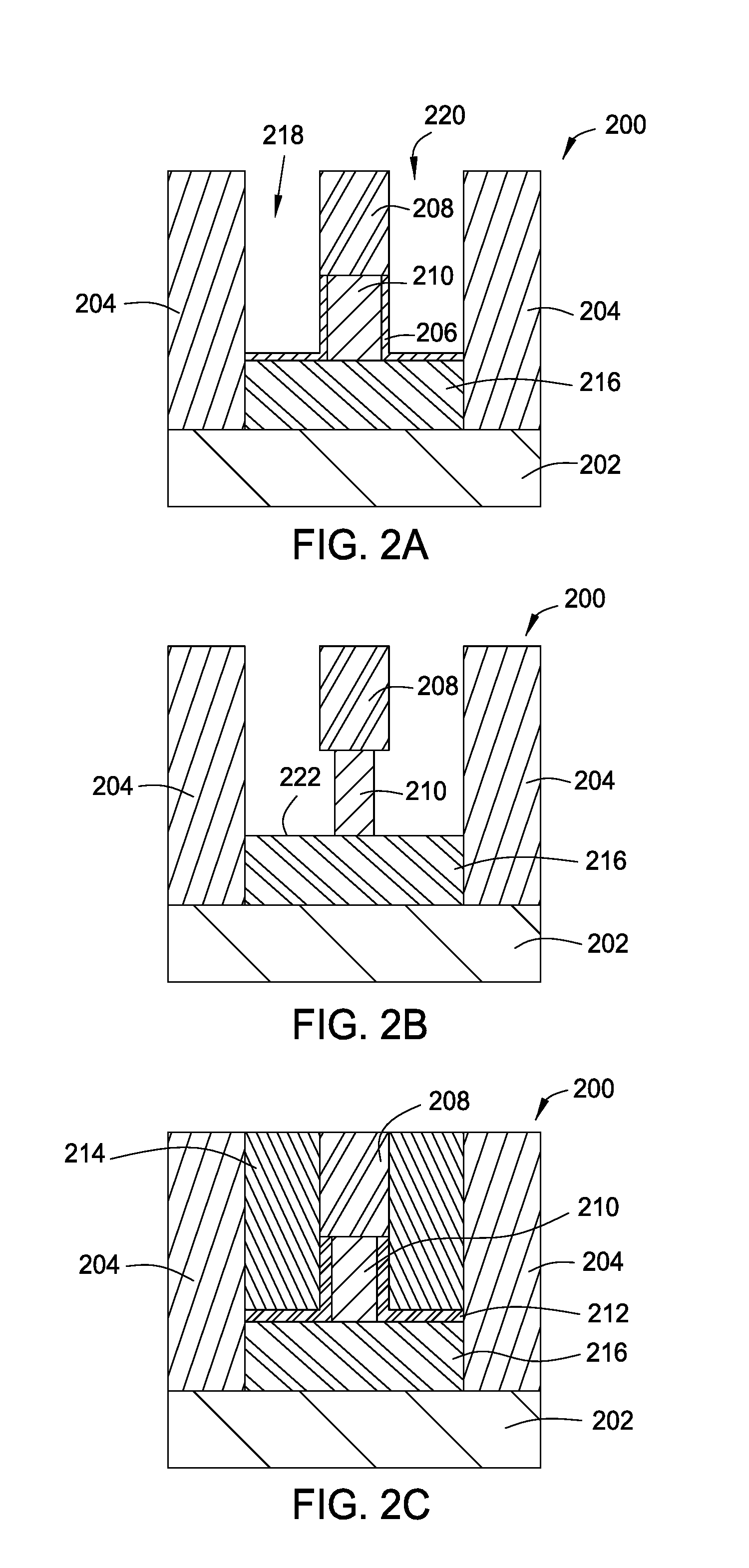
[0017] At operation 120 of FIG. 1, while a higher pressure environment is maintained, a salt is deposited on the pre source/drain region 216. In one implementation, a NH.sub.3/NF.sub.3/Ar gas mixture is delivered to the processing volume to react with the generated plasma and form a NH.sub.4F salt. The NH.sub.4F salt is deposited on the pre source/drain region 216. At operation 130, the workpiece is heated to greater than 90.degree. C. In one implementation, the workpiece is heated to greater than 90.degree. C. for greater than 1 minute. Heating the workpiece may remove the contaminants 206 to expose a clean silicon surface 222, as shown in FIG. 2B. In one implementation, the NH.sub.4F salt may react with and remove the native oxide contaminants 206 from the pre source/drain region 216 and fin layer 210. The NH.sub.4F salt may expose the underlying silicon surface 222 in the pre source/drain region 216 without damaging the underlying silicon surface. In one implementation, the NH.sub.3/NF.sub.3/Ar gas mixture is delivered to the processing volume which is maintained at a pressure of 200-900 mT. The continuous mode RF power may be maintained between 200-400 watts. The argon is flowed at a rate of 500-1200 sccm, the ammonia (NH.sub.3) is flowed at a rate of 10-100 sccm, and the NF.sub.3 is flowed at a rate of 5-20 sccm.
[0018] At operation 140, while the low pressure environment is maintained, the processing volume and gas lines are purged using a second inert gas mixture. The second inert gas may be a H.sub.2/Ar plasma mixture. The second inert gas mixture advantageously removes any residual ammonia (NH.sub.3) inside the chamber and gas line providing for a clean surface in preparation for subsequent processing operations.
[0019] As shown in FIG. 1, at operation 150, while the low pressure environment is maintained, the pre source/drain region 216 is recessed by etching. In one implementation, the fin layer 210 may also be recessed. In one implementation, the width of the fin layer 210 is reduced about between 1-2 nm. Suitable methods of etching the pre source/drain region 216 or the fin layer 210 or a combination of both include any suitable etching process, such as anisotropic dry etching. In one implementation, argon (Ar), hydrogen (H), and/or chlorine (CI) may be used as precursors to produce an etchant plasma for etching the fin layer 210. In another implementation, a H.sub.2/Cl.sub.2/Ar plasma is used for etching the pre source/drain region 216. The plasma mixture may function to volatilize the pre source/drain region 216 such that a portion may be removed. In one implementation, the pre source/drain region 216 is etched 1-2 nm or at a rate between 0.5 nm/min-3 nm/min. In one implementation, the plasma ion energy is less than 20 eV with plasma pulsing, the pressure of the processing volume may be maintained between 5-50 mTorr, the temperature is between 30.degree. C.-50.degree. C., and the RF power is between 500-600 watts. This step may use very low ion energy which is controlled by RF source pulsing without bias power. The argon may be flowed at a rate between 100-500 sccm, the hydrogen may be flowed at a rate between 50-300 sccm, and the chlorine may be flowed at a rate between 10-100 sccm. In one implementation, the ratio of Cl:H:Ar may be between 1:5:10 to 1:3:5. The low energy H.sub.2/Cl.sub.2/Ar plasma pulsing provides for precise control in the nm scale while reducing silicon-silicon lattice damage. The integrated clean and recess process provides for a source/drain region free of carbon and oxide contaminants while reducing the silicon-silicon lattice damage in preparation for subsequent processing.
[0020] As shown in FIG. 2C, a source/drain extension 212 may be deposited over the cleaned and recessed pre source/drain region 216. In one implementation, the source/drain extension 212 is silicon arsenide (SiAs). A source/drain layer 214 may be deposited on the source/drain extension 212. In one implementation, the source/drain layer 214 is silicon phosphide (SiP).
[0021] The integrated clean and recess process prepares the device 200 for subsequent processing while maintaining a low pressure environment. More specifically, the resulting source/drain region may be free of contaminants and/or defects, may has a desired shape, and may be prepared for subsequent epitaxial growth. The device 200 may undergo additional processing steps within the same cluster tool. Use of a single apparatus containing various processing chambers allows for the various operations of the method 100 of FIG. 1 to occur while maintaining a low pressure environment. More specifically, the low pressure environment need not be broken during transfer to an epitaxial chamber for source/drain extension 212 and source/drain layer 214 growth. In one implementation, additional processing may include replacing the dummy gate 208 with a metal gate.
[0022] Thus, methods described for cleaning and etching source/drain regions on a silicon substrate in preparation for precise Group IV source/drain growth in semiconductor devices are provided. Benefits of this disclosure include precise fin size control in devices, such as sub-10 nm FinFET devices, and increased overall device yield.
[0023] While the foregoing is directed to implementations of the present disclosure, other and further implementations of the disclosure may be devised without departing from the basic scope thereof, and the scope thereof is determined by the claims that follow.
* * * * *
D00000
D00001
D00002
XML
uspto.report is an independent third-party trademark research tool that is not affiliated, endorsed, or sponsored by the United States Patent and Trademark Office (USPTO) or any other governmental organization. The information provided by uspto.report is based on publicly available data at the time of writing and is intended for informational purposes only.
While we strive to provide accurate and up-to-date information, we do not guarantee the accuracy, completeness, reliability, or suitability of the information displayed on this site. The use of this site is at your own risk. Any reliance you place on such information is therefore strictly at your own risk.
All official trademark data, including owner information, should be verified by visiting the official USPTO website at www.uspto.gov. This site is not intended to replace professional legal advice and should not be used as a substitute for consulting with a legal professional who is knowledgeable about trademark law.