Reagent plate
Self , et al. May 25, 2
U.S. patent number D920,536 [Application Number D/664,916] was granted by the patent office on 2021-05-25 for reagent plate. This patent grant is currently assigned to Becton, Dickinson and Company. The grantee listed for this patent is Becton, Dickinson and Company. Invention is credited to Dwight Livingston, Brian A. Self, Alyssa Shedlosky.


| United States Patent | D920,536 |
| Self , et al. | May 25, 2021 |
Reagent plate
Claims
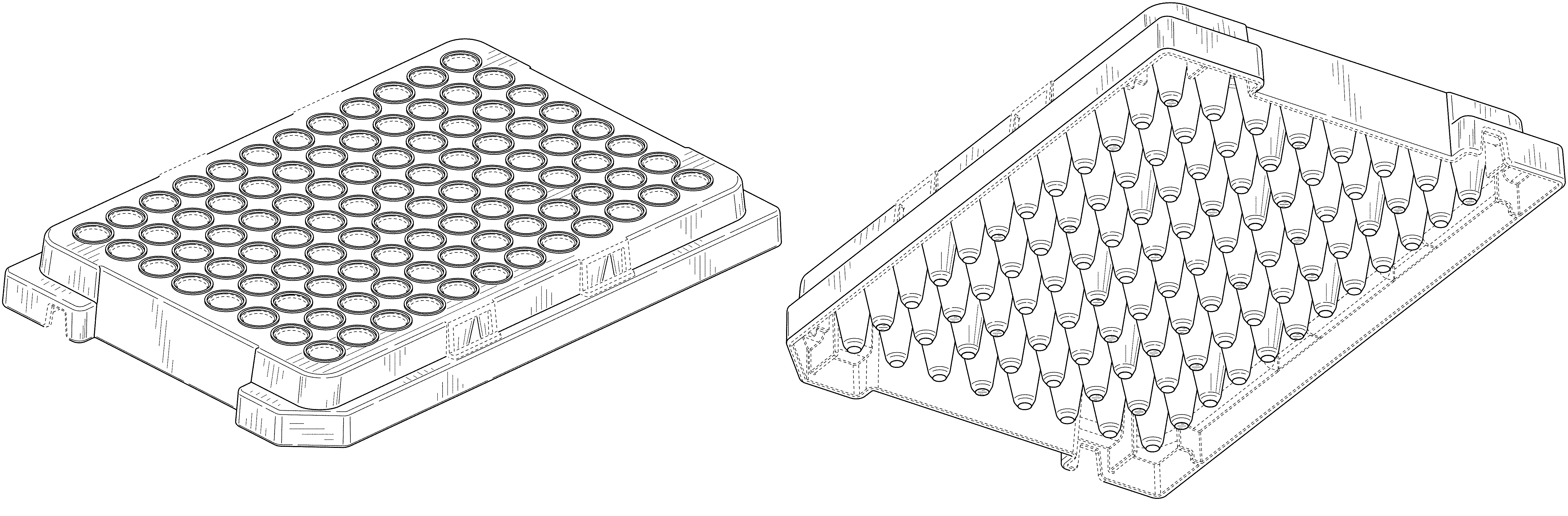
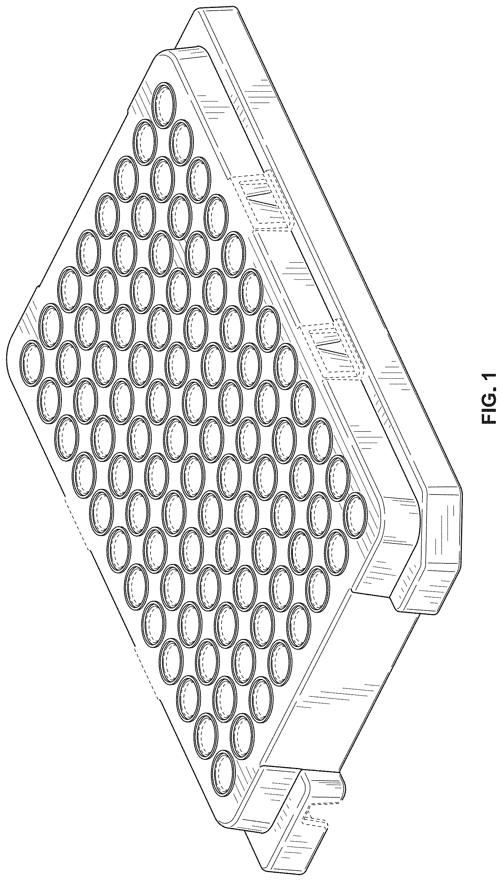
CLAIM The ornamental design for a reagent plate, as shown and described.
| Inventors: | Self; Brian A. (Monkton, MD), Livingston; Dwight (Fallston, MD), Shedlosky; Alyssa (Owings Mills, MD) | ||||||||||
|---|---|---|---|---|---|---|---|---|---|---|---|
| Applicant: |
|
||||||||||
| Assignee: | Becton, Dickinson and Company
(Franklin Lakes, NJ) |
||||||||||
| Appl. No.: | D/664,916 | ||||||||||
| Filed: | September 28, 2018 |
| Current U.S. Class: | D24/227; D24/229 |
| Current International Class: | 2402 |
| Field of Search: | ;D24/121,224,226,227,229,230 ;D9/756-758 |
References Cited [Referenced By]
U.S. Patent Documents
| 4483925 | November 1984 | Noack |
| 4725388 | February 1988 | Nelson |
| 5858309 | January 1999 | Mathus et al. |
| 5922289 | July 1999 | Wong |
| 5948363 | September 1999 | Gaillard |
| 5962250 | October 1999 | Gavin et al. |
| D420743 | February 2000 | Monks |
| 6074614 | June 2000 | Hafeman et al. |
| 6099230 | August 2000 | Hitch |
| D441091 | April 2001 | Day |
| 6426215 | July 2002 | Sandell |
| D466219 | November 2002 | Wynschenk et al. |
| D469544 | January 2003 | Lafond et al. |
| 6540965 | April 2003 | Bara |
| 6767607 | July 2004 | Tanner et al. |
| 7128878 | October 2006 | Muser |
| 7176809 | February 2007 | Ganz et al. |
| 7211224 | May 2007 | Olivier |
| 7309603 | December 2007 | Ma et al. |
| 7347977 | March 2008 | Guelzow et al. |
| 7531140 | May 2009 | Szlosek |
| D598128 | August 2009 | Pihl et al. |
| D601713 | October 2009 | Lohn et al. |
| D601714 | October 2009 | Lohn et al. |
| 7674346 | March 2010 | Clements et al. |
| D628305 | November 2010 | Gorrec et al. |
| D628306 | November 2010 | Blanc et al. |
| D639447 | June 2011 | Karpiloff |
| D699371 | February 2014 | Williams et al. |
| 8728415 | May 2014 | Seippel |
| D710024 | July 2014 | Guo |
| 8858718 | October 2014 | Gifford et al. |
| 8877141 | November 2014 | Yu |
| 8906327 | December 2014 | Williams |
| D724236 | March 2015 | Motadel et al. |
| D729942 | May 2015 | Keizer et al. |
| D732187 | June 2015 | Houkal et al. |
| 9168532 | October 2015 | Malinoski et al. |
| D745698 | December 2015 | Rage et al. |
| D808540 | January 2018 | Johns et al. |
| D812243 | March 2018 | Johns et al. |
| D826426 | August 2018 | Muller |
| D840053 | February 2019 | Kamees |
| D906537 | December 2020 | Sims |
| 2001/0051112 | December 2001 | Gulzow et al. |
| 2002/0104795 | August 2002 | Cote et al. |
| 2002/0192119 | December 2002 | DeSilets et al. |
| 2005/0058578 | March 2005 | Guelzow |
| 2005/0136546 | June 2005 | Berndt et al. |
| 2005/0170498 | August 2005 | Dolley et al. |
| 2005/0179562 | August 2005 | Ganz |
| 2008/0095673 | April 2008 | Xu |
| 2009/0275116 | November 2009 | Subramanyam |
| 2009/0280032 | November 2009 | Super et al. |
| 2011/0286897 | November 2011 | Uschkureit et al. |
| 2013/0315800 | November 2013 | Yin et al. |
| 2014/0205518 | July 2014 | Malinoski et al. |
| 2014/0361022 | December 2014 | Finneran |
| 2015/0209786 | July 2015 | Hage |
| 2015/0309025 | October 2015 | Van Praet et al. |
| 2017/0136467 | May 2017 | Johns et al. |
| 2017/0298313 | October 2017 | Moorhead |
| 2020/0164365 | May 2020 | King |
| 2020/0346210 | November 2020 | Hubbuch |
| 2020/0360918 | November 2020 | Chen |
| 2020/0391215 | December 2020 | Cox |
| 2020/0408695 | December 2020 | Dragna |
| 003342732-0013 | Aug 2016 | EM | |||
| 003342732-0014 | Aug 2016 | EM | |||
| 003372614-0004 | Sep 2016 | EM | |||
| 003372614-0005 | Sep 2016 | EM | |||
Other References
|
Design U.S. Appl. No. 29/564,499, filed May 13, 2016 entitled "Reagent Plate" (Not Yet Published). cited by applicant . Design U.S. Appl. No. 29/575,816, filed Aug. 29, 2016, entitled "Reagent Plate". (Not Yet Published). cited by applicant . Various Images of a product offered for sale prior to May 13, 2016. cited by applicant . Canadian Examination Report for Application No. 186562 dated Oct. 16, 2020, 4 pages. cited by applicant. |
Primary Examiner: Hallmark; Janice
Assistant Examiner: Agilee; Omeed
Attorney, Agent or Firm: Lerner, David, Littenberg, Krumholz & Mentlik, LLP
Description
FIG. 1 is a front perspective view of a reagent plate according to our design;
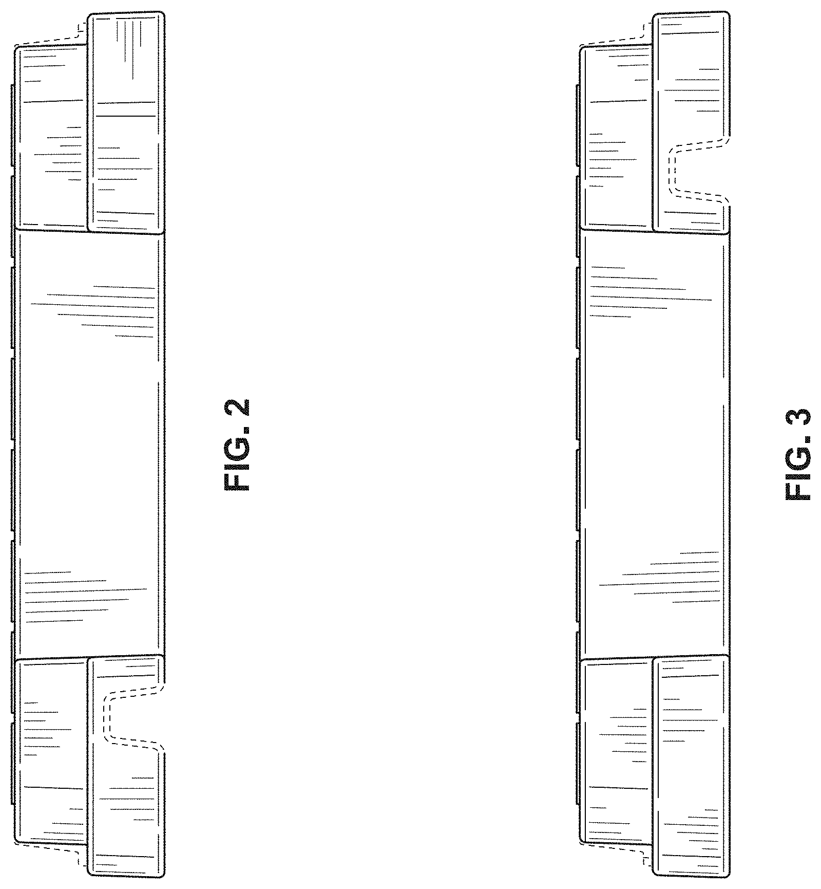
FIG. 2 is a front elevation view thereof;
FIG. 3 is a rear elevation view thereof;
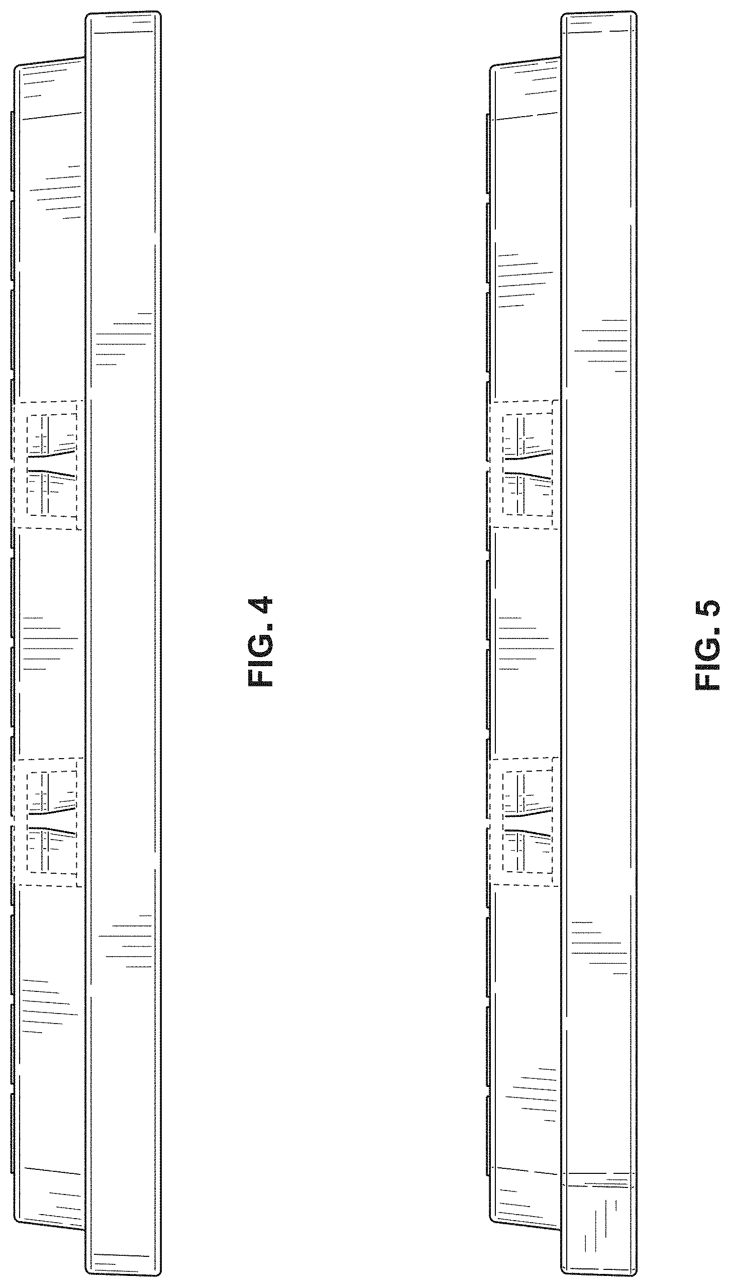
FIG. 4 is a left side elevation view thereof;
FIG. 5 is a right side elevation view thereof;
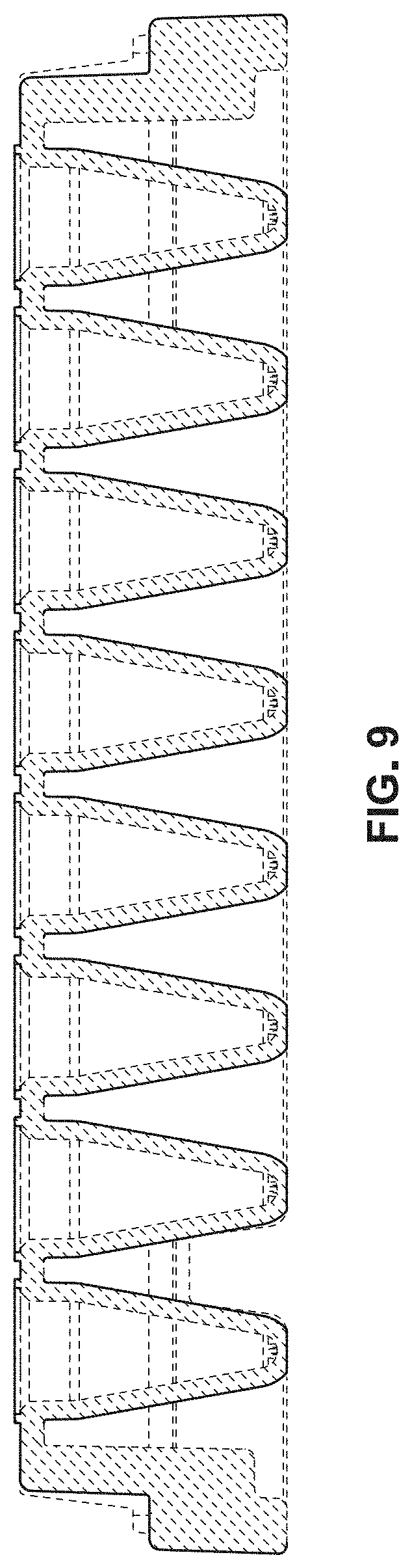
FIG. 6 is a top plan view thereof;
FIG. 7 is a bottom plan view thereof;
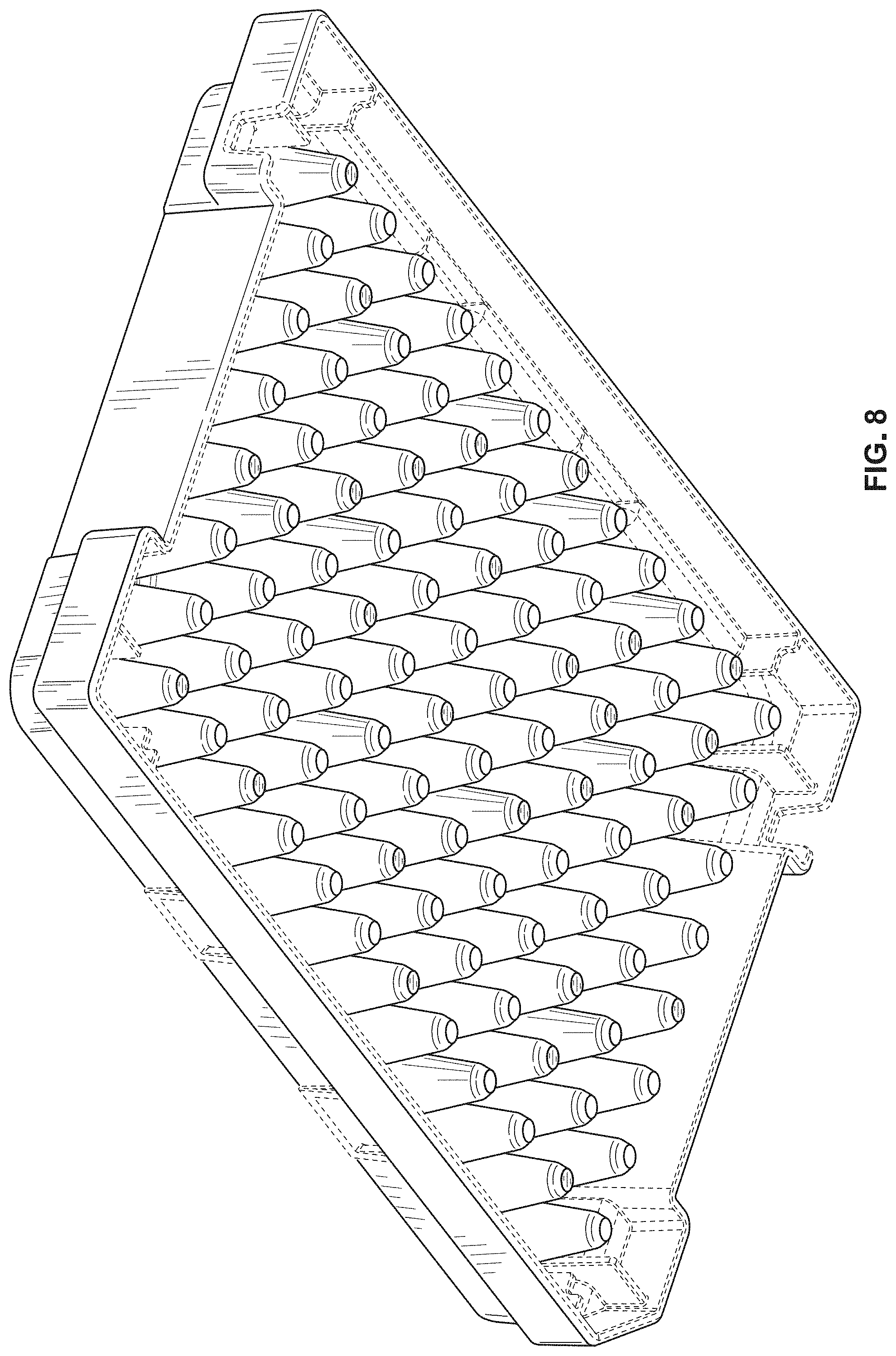
FIG. 8 is a rear bottom perspective view thereof; and,
FIG. 9 is a cross-sectional view taken along line 9-9 of FIG. 6.
The broken lines of even length shown in the drawings depict portions of the reagent plate that form no part of the claimed design. The broken lines of uneven length represent boundary lines that form no part of the claimed design.
* * * * *
D00000
D00001
D00002
D00003
D00004
D00005
D00006
D00007
XML
uspto.report is an independent third-party trademark research tool that is not affiliated, endorsed, or sponsored by the United States Patent and Trademark Office (USPTO) or any other governmental organization. The information provided by uspto.report is based on publicly available data at the time of writing and is intended for informational purposes only.
While we strive to provide accurate and up-to-date information, we do not guarantee the accuracy, completeness, reliability, or suitability of the information displayed on this site. The use of this site is at your own risk. Any reliance you place on such information is therefore strictly at your own risk.
All official trademark data, including owner information, should be verified by visiting the official USPTO website at www.uspto.gov. This site is not intended to replace professional legal advice and should not be used as a substitute for consulting with a legal professional who is knowledgeable about trademark law.