Tire
Matturro , et al. May 4, 2
U.S. patent number D918,126 [Application Number D/714,122] was granted by the patent office on 2021-05-04 for tire. This patent grant is currently assigned to Bridgestone Europe NV/SA. The grantee listed for this patent is Bridgestone Europe NV/SA. Invention is credited to Andrea Busato, Gabriele De Filippis, Daniele Matturro, Takamitsu Nakamura, Antonio Tirone.
View All Diagrams
| United States Patent | D918,126 |
| Matturro , et al. | May 4, 2021 |
Tire
Claims
CLAIM The ornamental design for a tire, as shown and described.
| Inventors: | Matturro; Daniele (Rome, IT), Nakamura; Takamitsu (Rome, IT), Busato; Andrea (Rome, IT), Tirone; Antonio (Rome, IT), De Filippis; Gabriele (Rome, IT) | ||||||||||
|---|---|---|---|---|---|---|---|---|---|---|---|
| Applicant: |
|
||||||||||
| Assignee: | Bridgestone Europe NV/SA
(Zaventem, BE) |
||||||||||
| Appl. No.: | D/714,122 | ||||||||||
| Filed: | November 21, 2019 |
Foreign Application Priority Data
| May 21, 2019 [EM] | 006493128-0001 | |||
| May 21, 2019 [EM] | 006493128-0002 | |||
| Current U.S. Class: | D12/517 |
| Current International Class: | 1215 |
| Field of Search: | ;D12/500-532,604 |
References Cited [Referenced By]
U.S. Patent Documents
| D646626 | October 2011 | Murata |
| D665336 | August 2012 | Skurich |
| D667360 | September 2012 | Ishida |
| D700878 | March 2014 | Takemoto |
| D726100 | April 2015 | Jeong |
| D730809 | June 2015 | Bonifas |
| D798803 | October 2017 | Wang |
| D798804 | October 2017 | Wang |
| D821961 | July 2018 | Wakasugi |
| D887343 | June 2020 | Hoshiba |
| D900709 | November 2020 | Trine |
| D904280 | December 2020 | Kuwahara |
| M000656442-0001 | Feb 2007 | EM | |||
| M000656442-0002 | Feb 2007 | EM | |||
| M001281083-0001 | Jun 2011 | EM | |||
| M002625418-0002 | Mar 2015 | EM | |||
Description
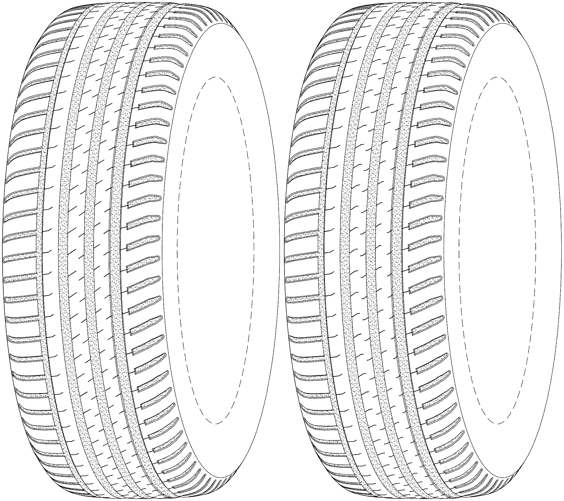
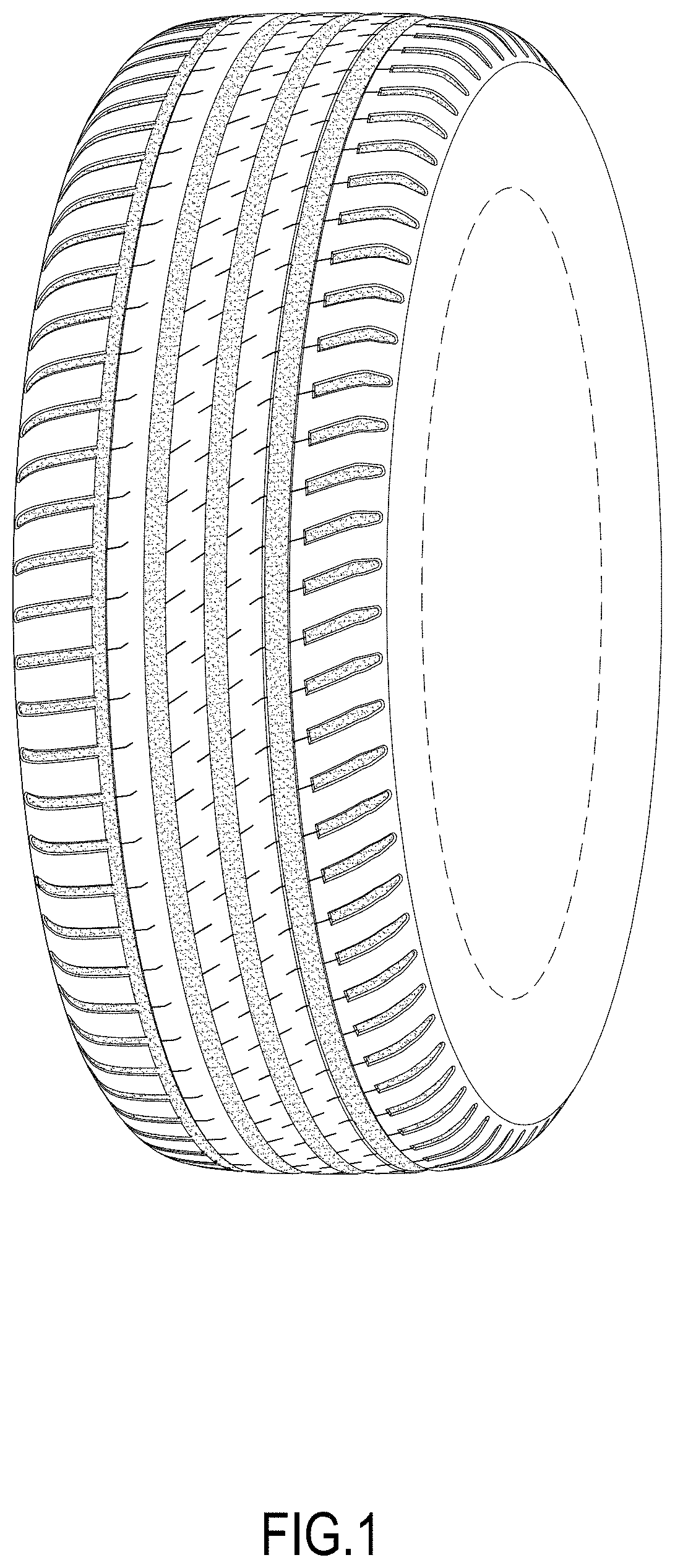
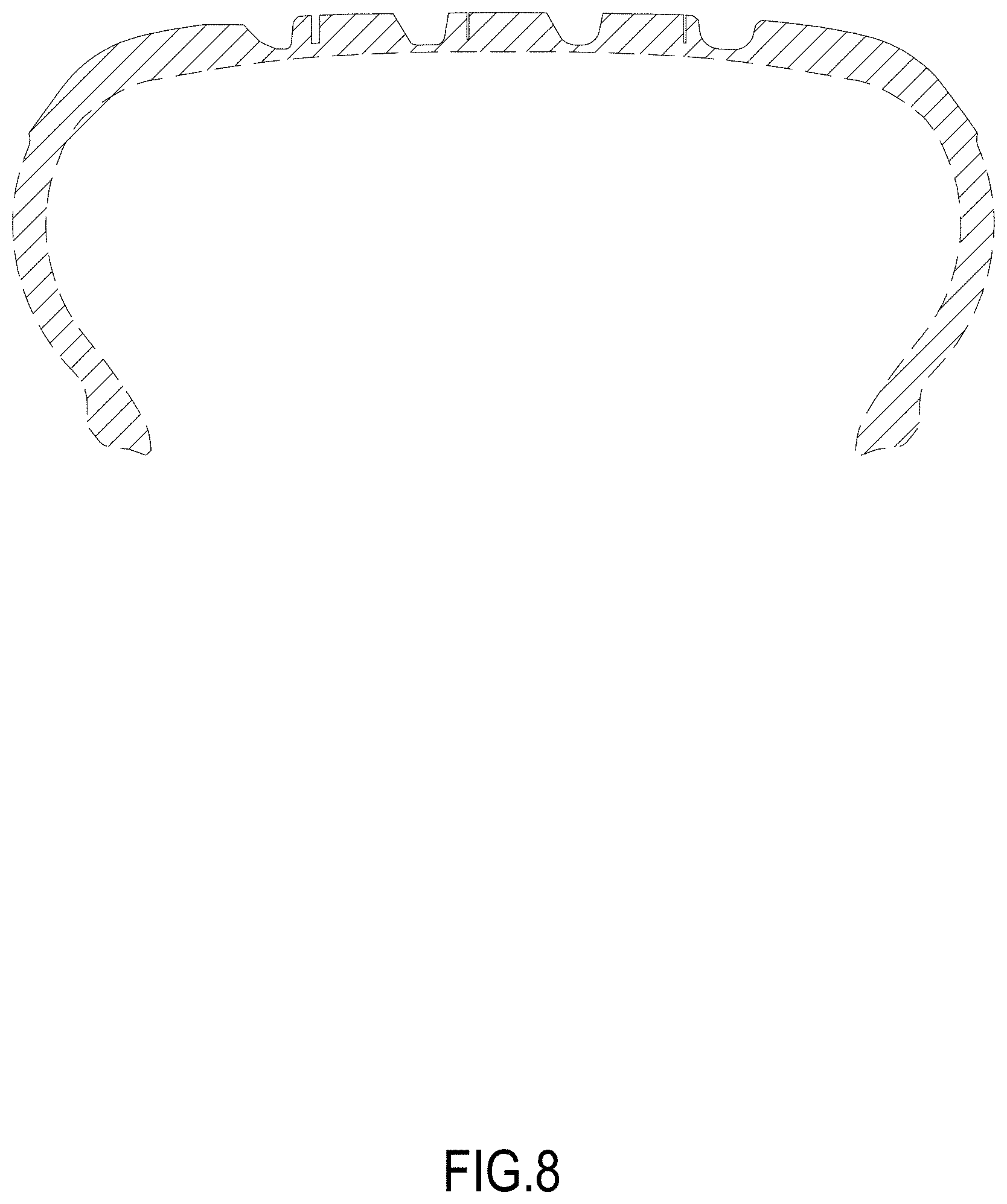
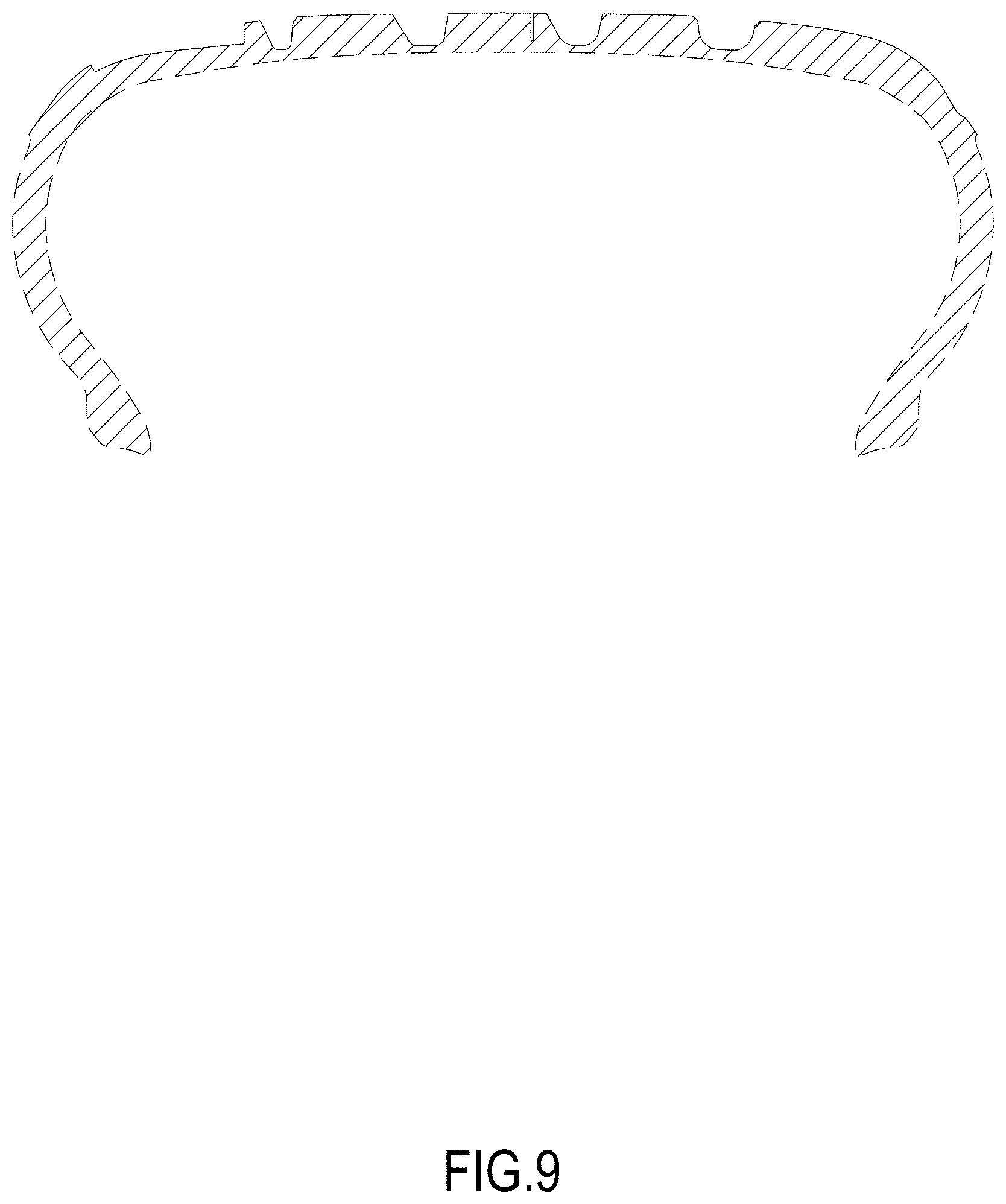
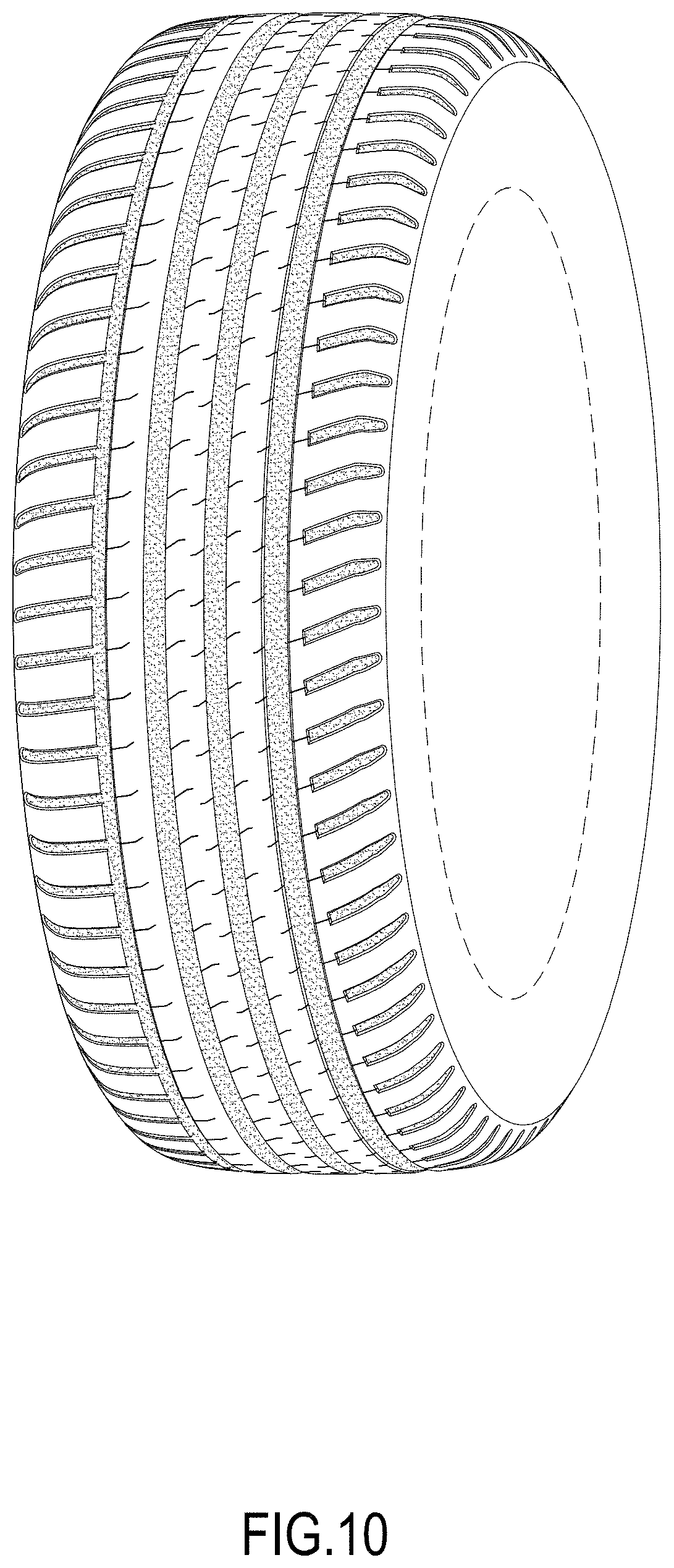
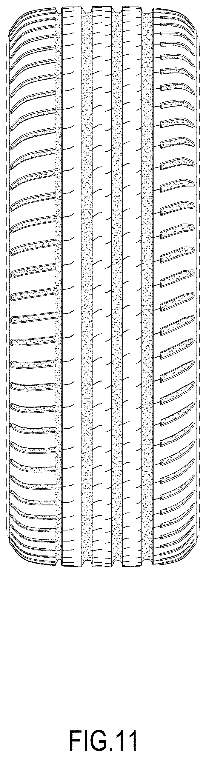
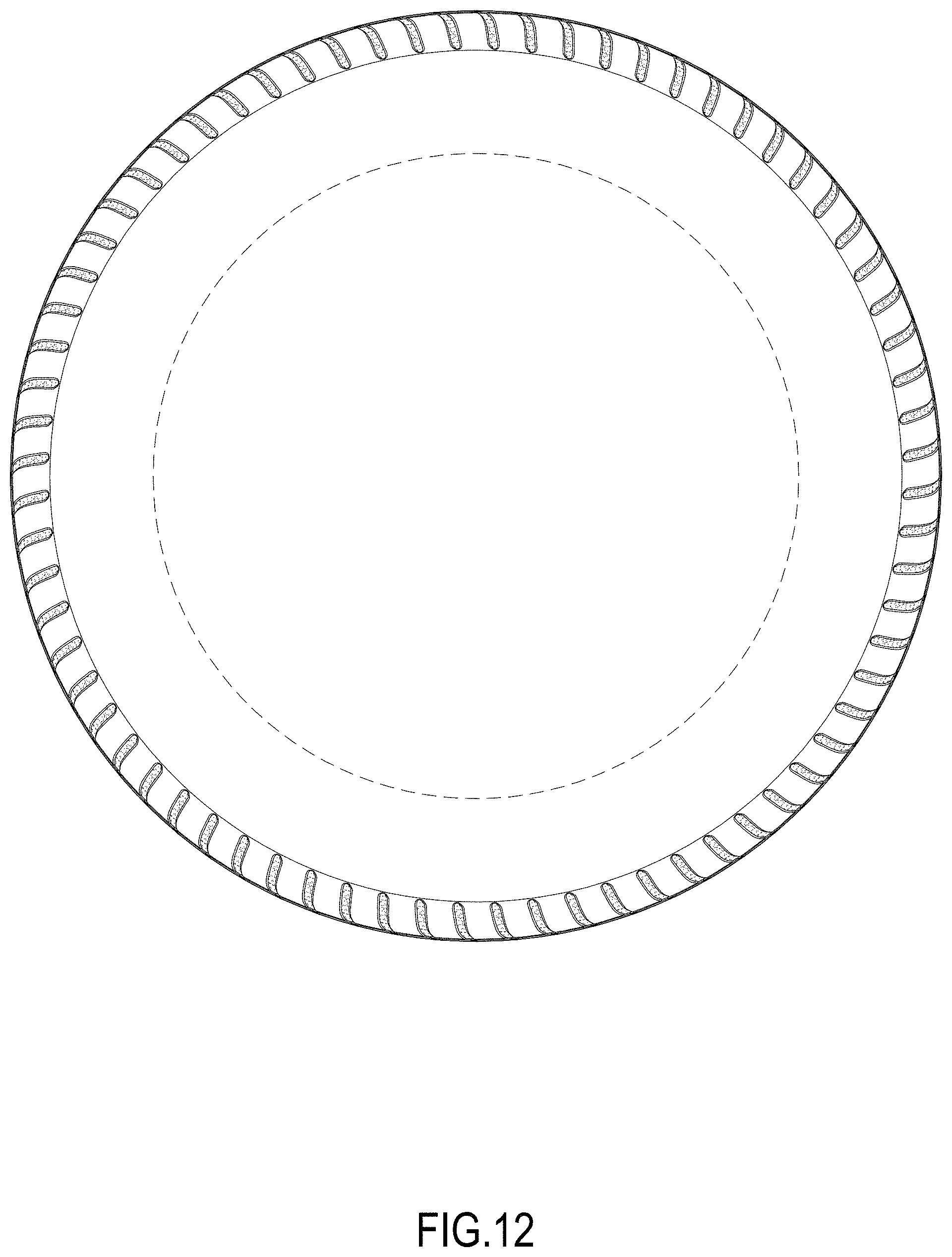
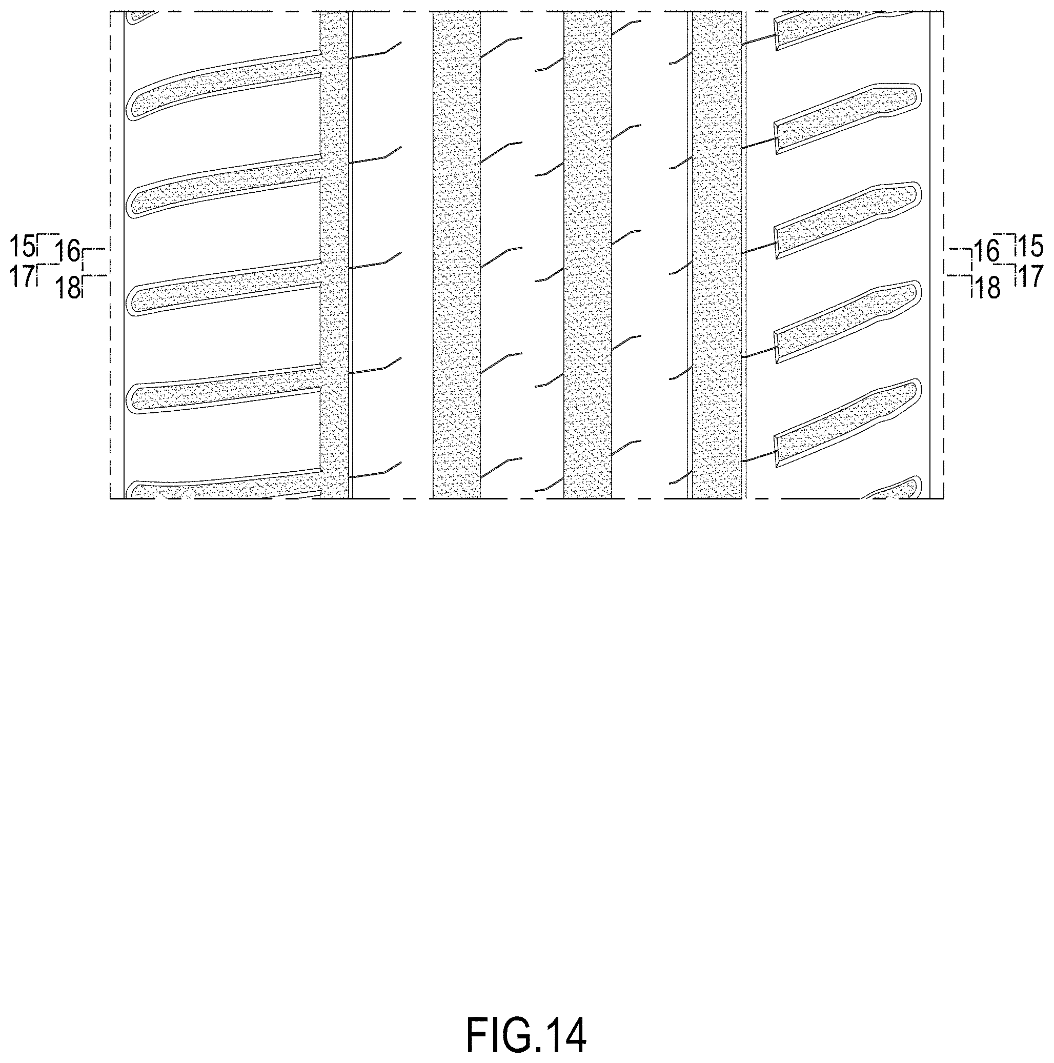
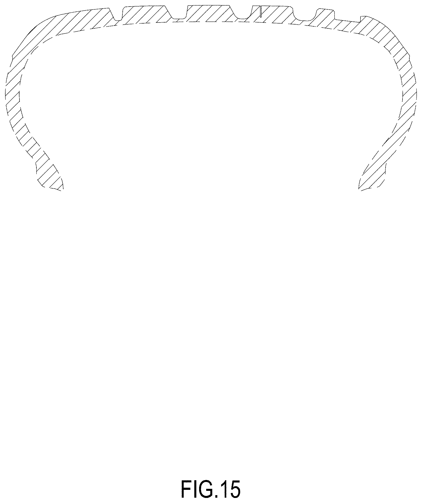
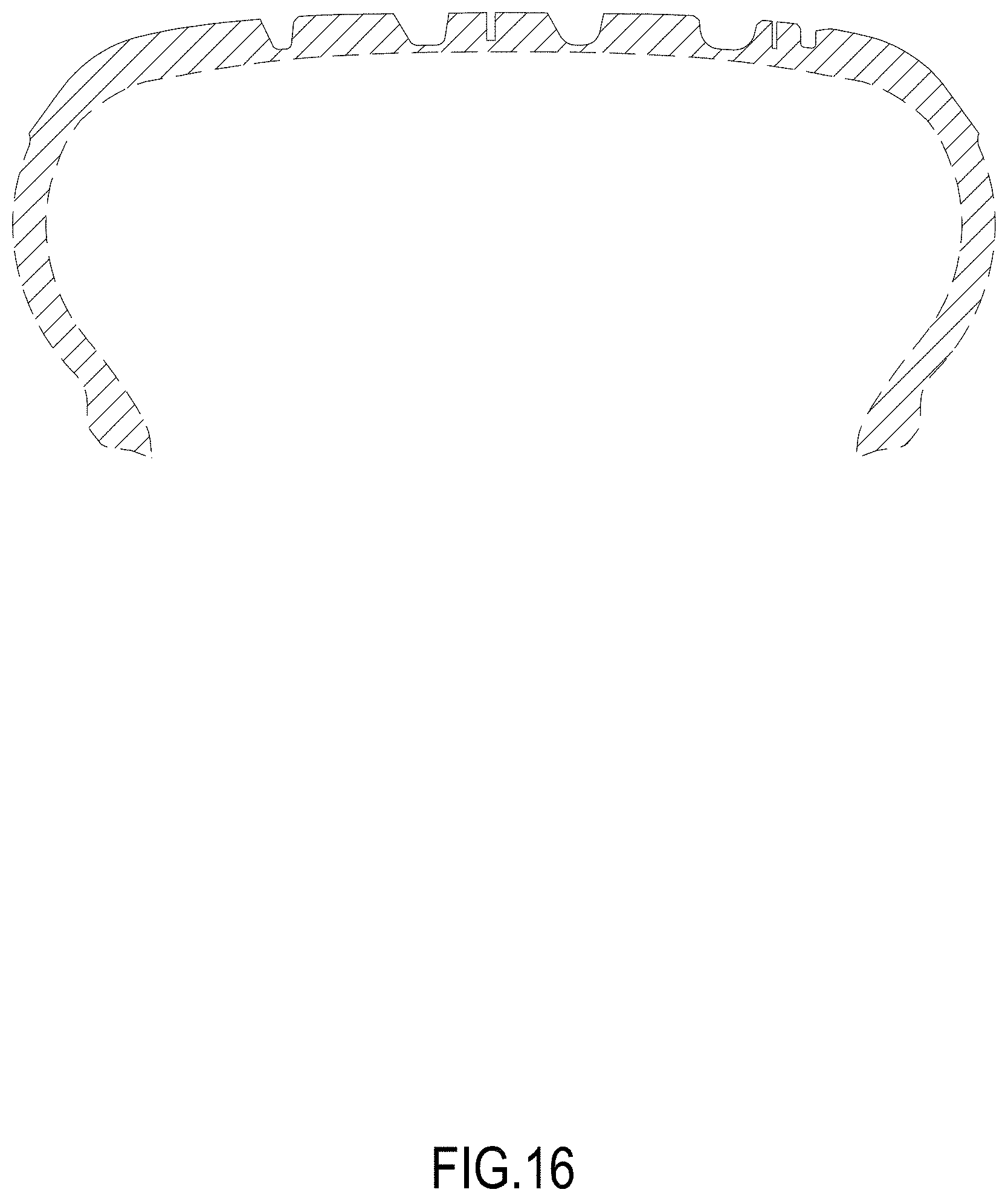
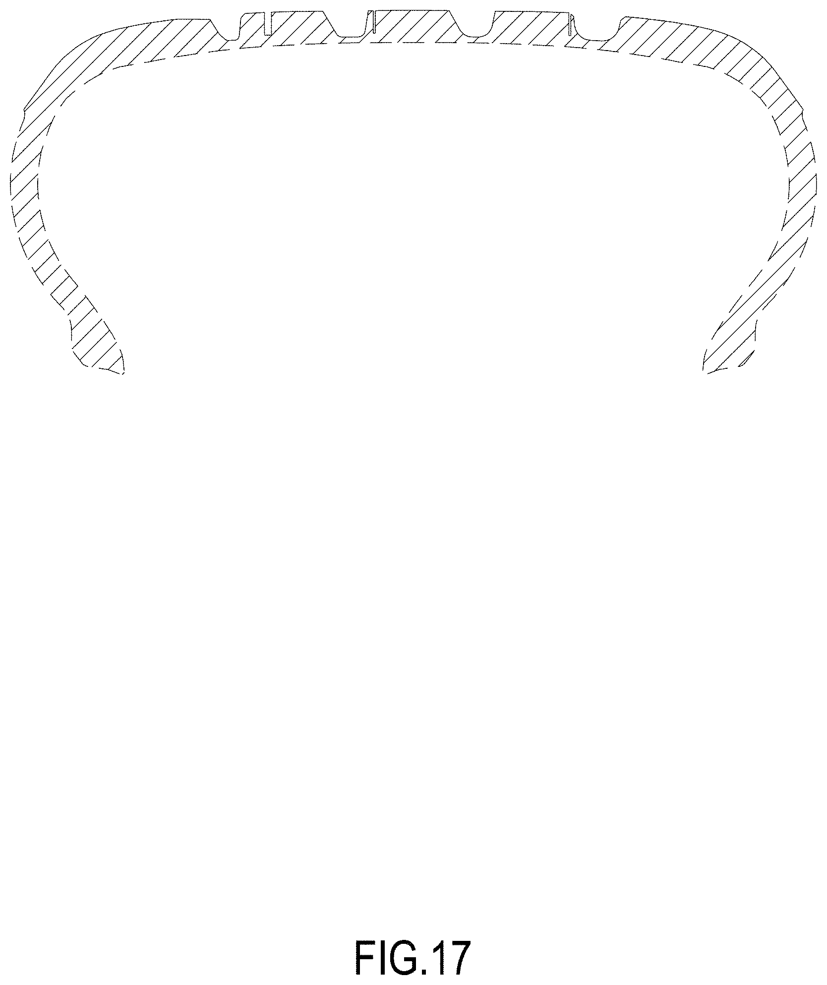
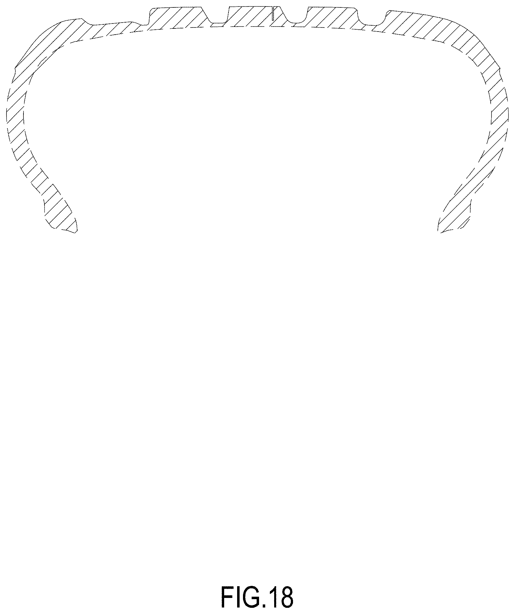
FIGS. 1 through 9 relate to the first embodiment of our new tire design. FIGS. 10 through 18 relate to the second embodiment of our new tire design.
FIG. 1 is a perspective view of the first embodiment of the tire;
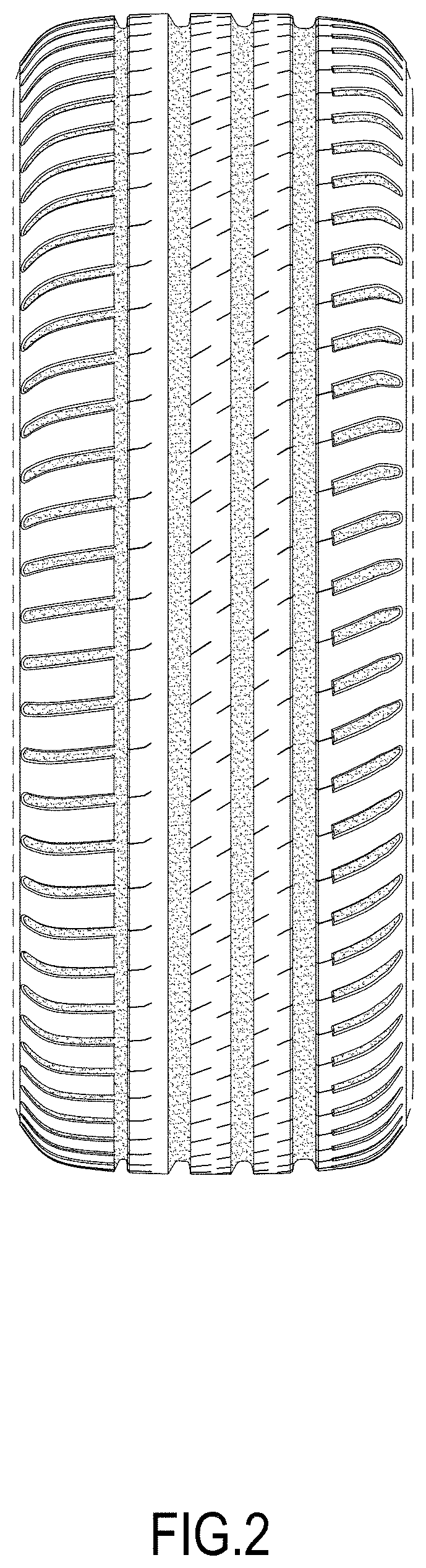
FIG. 2 is a front view of the tire;
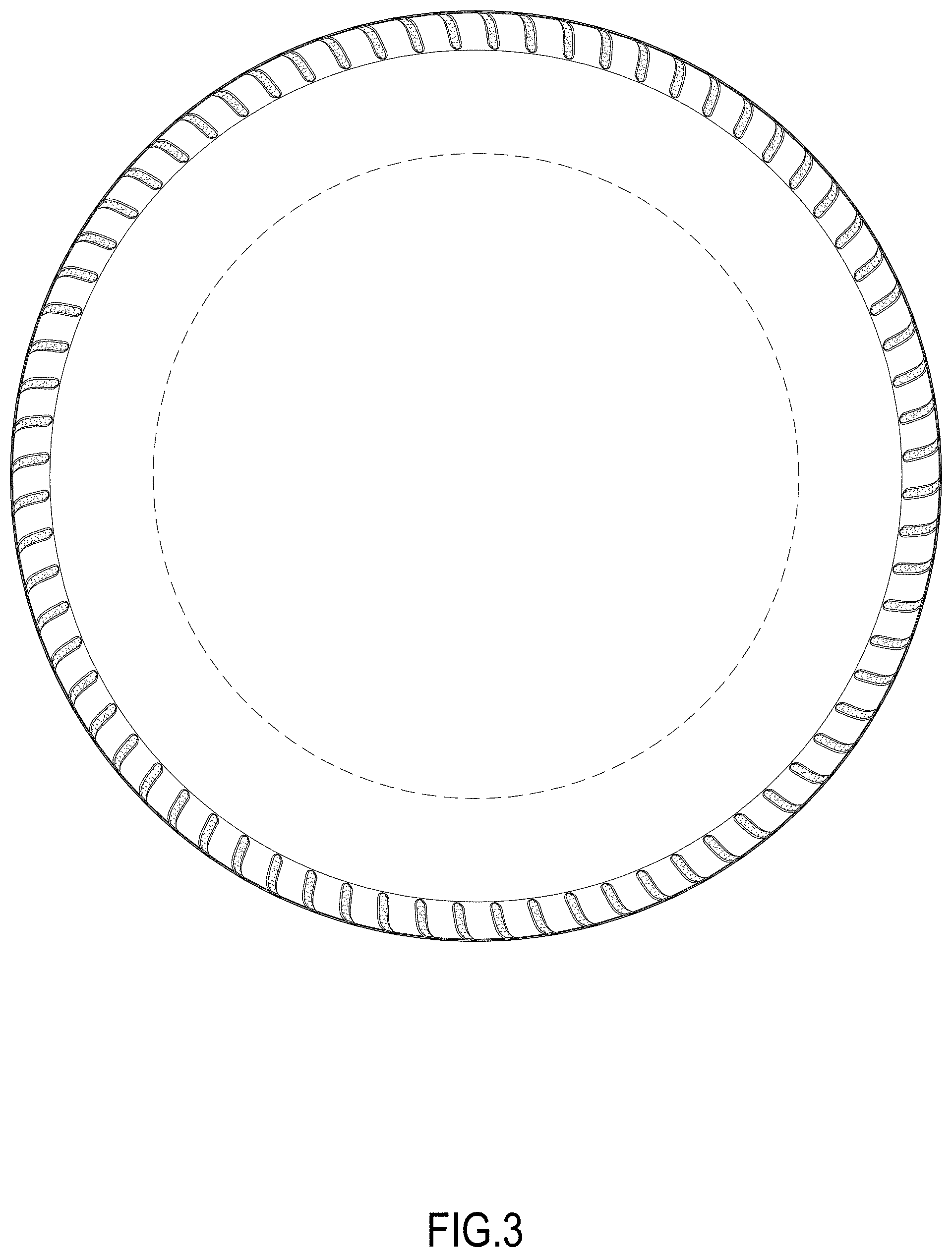
FIG. 3 is a right view of the tire;
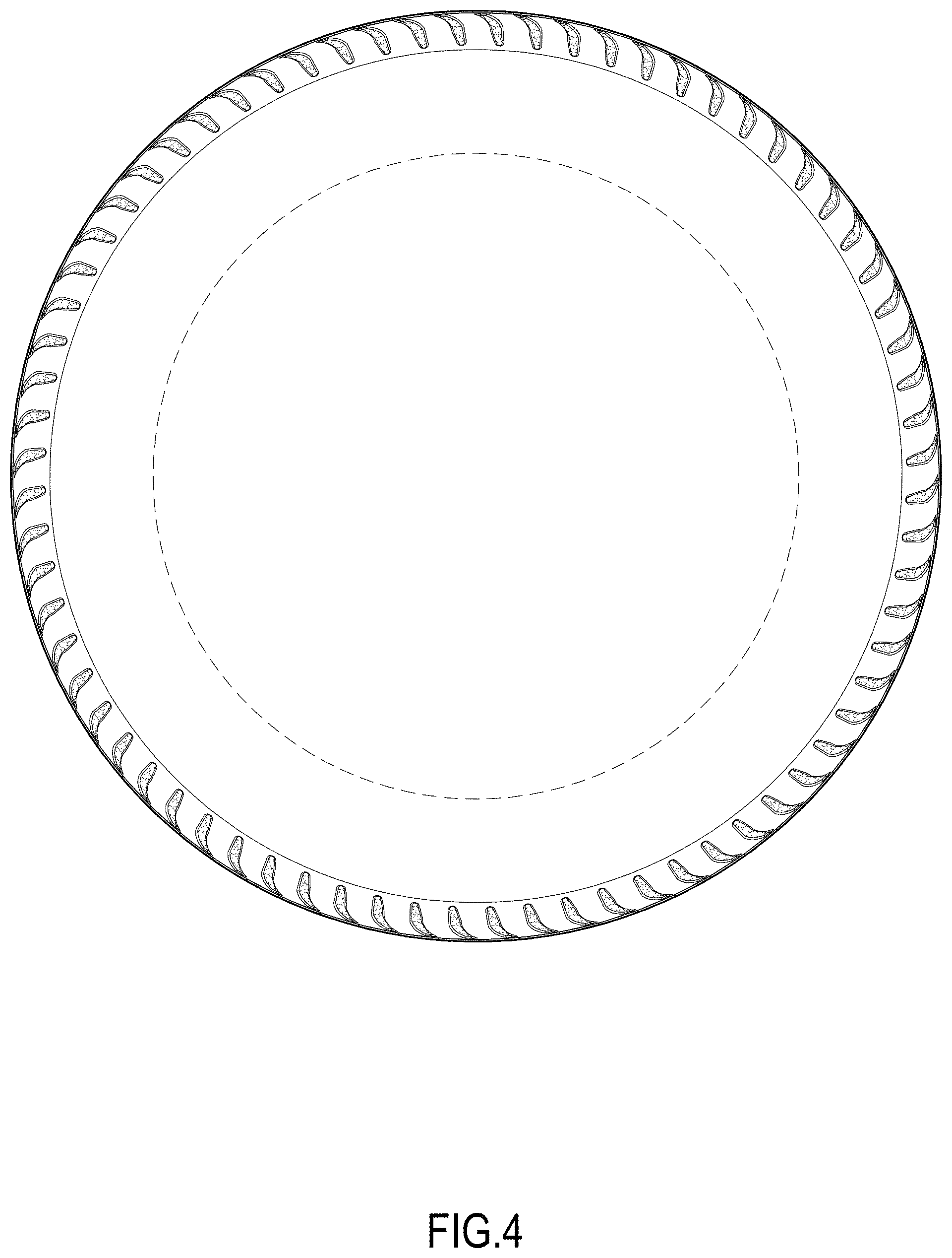
FIG. 4 is a left view of the tire;
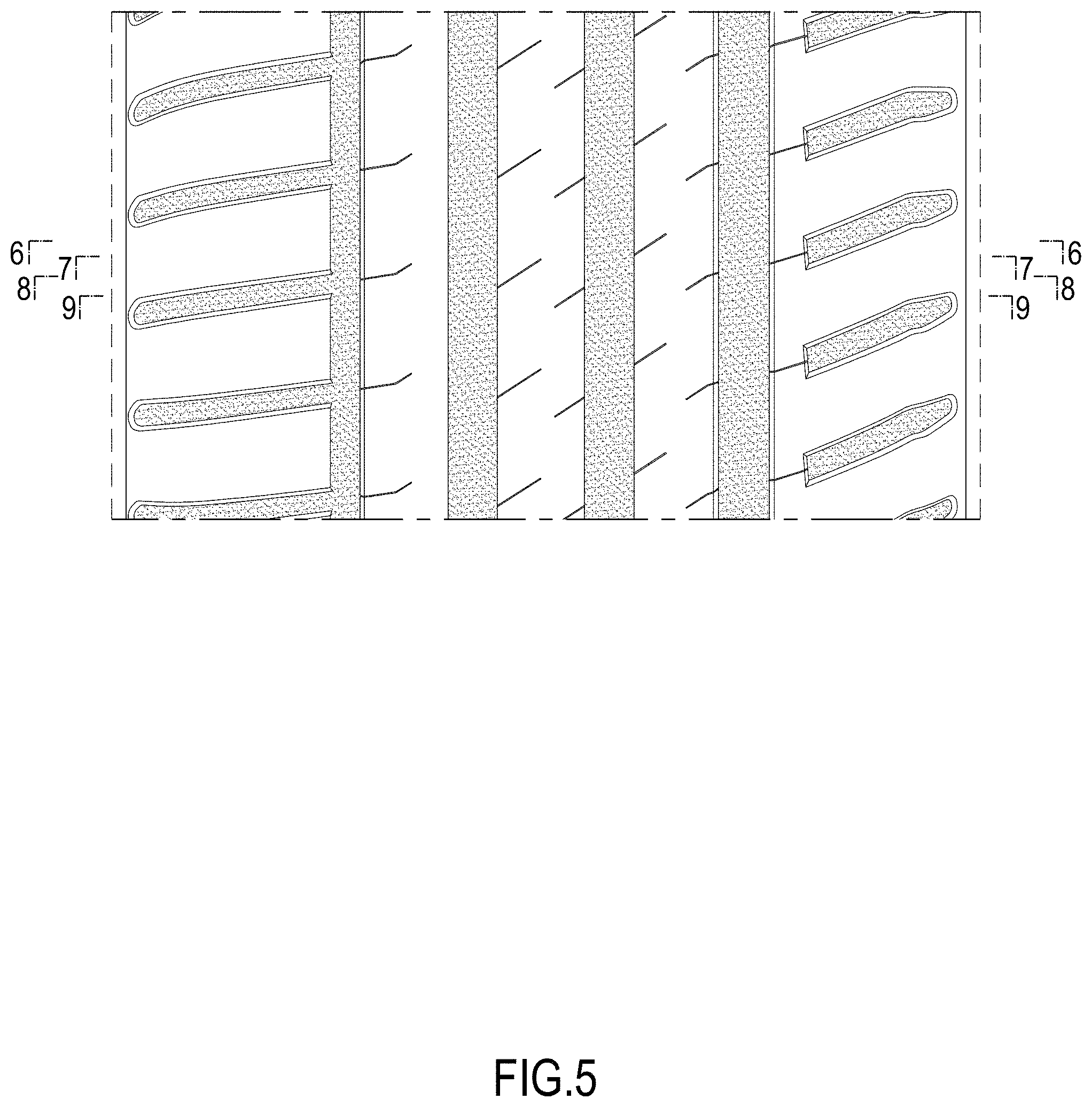
FIG. 5 is an enlarged view of the tire with section lines related to views 6, 7, 8, 9;
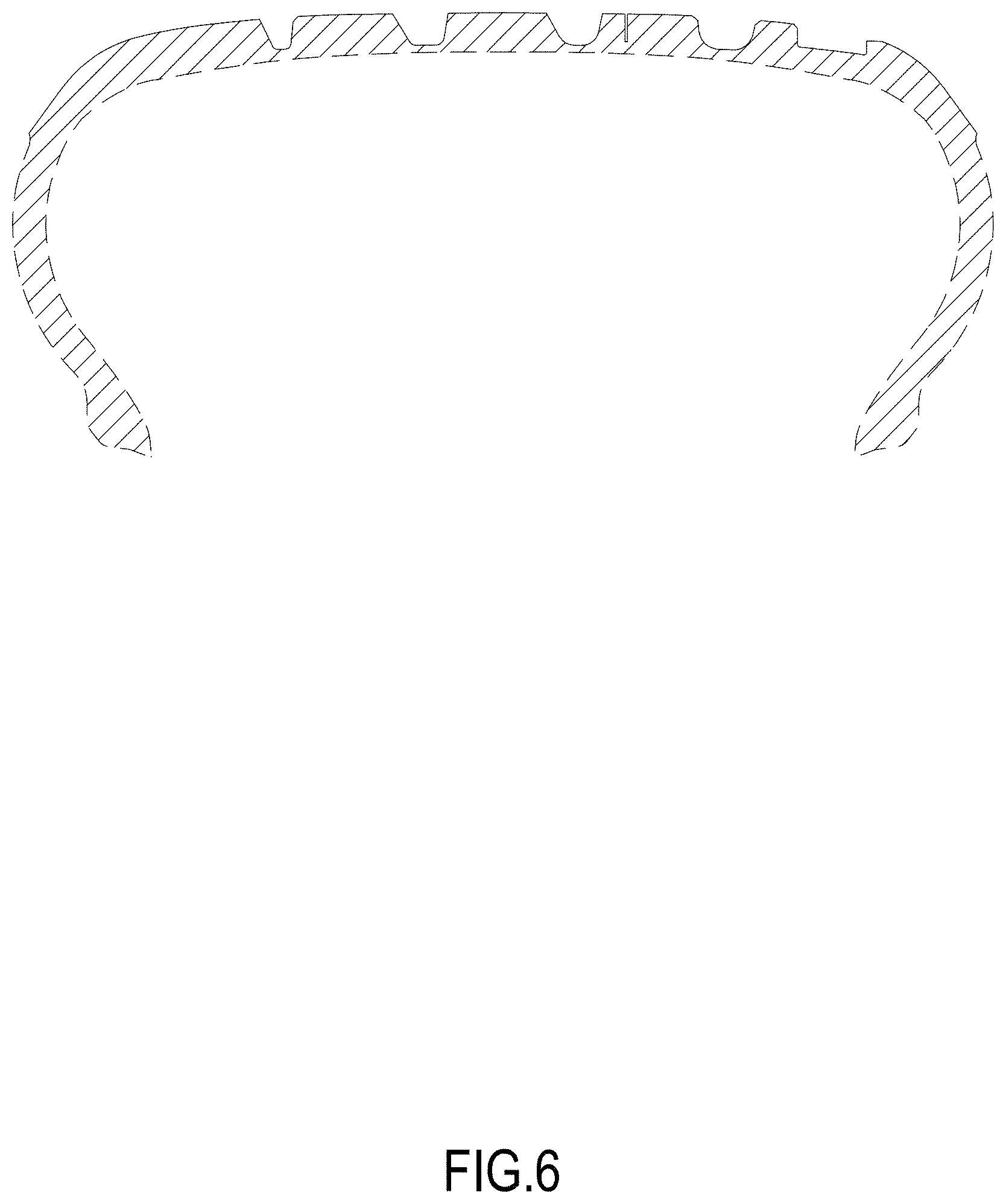
FIG. 6 is a first transversal section view of the tire taken along line 6-6;
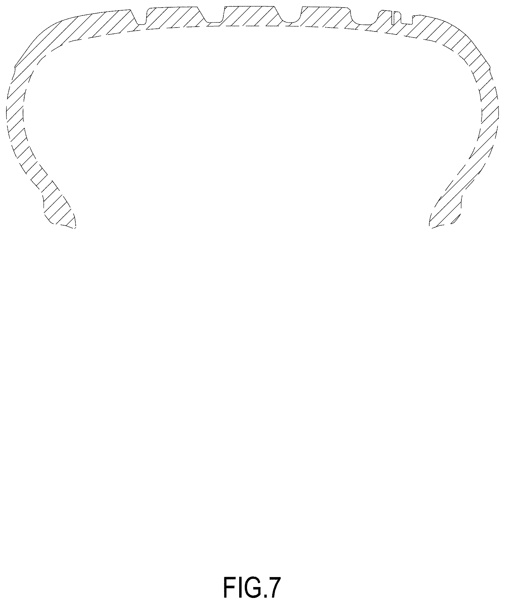
FIG. 7 is a second transversal section view of the tire taken along line 7-7;
FIG. 8 is a third transversal section view of the tire taken along line 8-8;
FIG. 9 is a fourth transversal section view of the tire taken along line 9-9;
FIG. 10 is a perspective view of the second embodiment of the tire;
FIG. 11 is a front view of the tire;
FIG. 12 is a right view of the tire;
FIG. 13 is a left view of the tire;
FIG. 14 is an enlarged view of the tire with section lines related to views 15, 16, 17, 18;
FIG. 15 is a first transversal section view of the tire taken along line 15-15;
FIG. 16 is a second transversal section view of the tire taken along line 16-16;
FIG. 17 is a third transversal section view of the tire taken along line 17-17; and,
FIG. 18 is a fourth transversal section view of the tire taken along line 18-18.
The broken lines defining the sidewall and inner bead depict environmental subject matter that forms no part of the claimed design.
* * * * *
D00000
D00001
D00002
D00003
D00004
D00005
D00006
D00007
D00008
D00009
D00010
D00011
D00012
D00013

D00014
D00015
D00016
D00017
D00018
XML
uspto.report is an independent third-party trademark research tool that is not affiliated, endorsed, or sponsored by the United States Patent and Trademark Office (USPTO) or any other governmental organization. The information provided by uspto.report is based on publicly available data at the time of writing and is intended for informational purposes only.
While we strive to provide accurate and up-to-date information, we do not guarantee the accuracy, completeness, reliability, or suitability of the information displayed on this site. The use of this site is at your own risk. Any reliance you place on such information is therefore strictly at your own risk.
All official trademark data, including owner information, should be verified by visiting the official USPTO website at www.uspto.gov. This site is not intended to replace professional legal advice and should not be used as a substitute for consulting with a legal professional who is knowledgeable about trademark law.