Fixed wing aircraft with tilt rotors
Vander Lind , et al. A
U.S. patent number D892,710 [Application Number D/676,186] was granted by the patent office on 2020-08-11 for fixed wing aircraft with tilt rotors. This patent grant is currently assigned to Kitty Hawk Corporation. The grantee listed for this patent is Kitty Hawk Corporation. Invention is credited to Gregory Mainland Horn, Campbell McLaren, Pranay Sinha, Damon Vander Lind.


| United States Patent | D892,710 |
| Vander Lind , et al. | August 11, 2020 |
Fixed wing aircraft with tilt rotors
Claims
CLAIM We claim the ornamental design for a fixed wing aircraft with tilt rotors, as shown and described.
| Inventors: | Vander Lind; Damon (East Palo Alto, CA), Sinha; Pranay (Sunnyvale, CA), McLaren; Campbell (Alameda, CA), Horn; Gregory Mainland (Mountain View, CA) | ||||||||||
|---|---|---|---|---|---|---|---|---|---|---|---|
| Applicant: |
|
||||||||||
| Assignee: | Kitty Hawk Corporation (Palo
Alto, CA) |
||||||||||
| Appl. No.: | D/676,186 | ||||||||||
| Filed: | January 9, 2019 |
| Current U.S. Class: | D12/344 |
| Current International Class: | 1207 |
| Field of Search: | ;D12/1,2,3,4,16.1,319-345 ;D21/437-455 |
References Cited [Referenced By]
U.S. Patent Documents
| D199070 | September 1964 | Ruttner |
| D431610 | October 2000 | Comacho |
| D492970 | July 2004 | Tabor |
| D678169 | March 2013 | Kennelly |
| 9475579 | October 2016 | Fredericks |
| D799402 | October 2017 | Cummings |
| 10071801 | September 2018 | North |
| D832141 | October 2018 | Ferner |
| D850357 | June 2019 | Cummings |
| 10414483 | September 2019 | Ivans |
| 10479482 | November 2019 | Kuentzel |
| D873202 | January 2020 | Tzarnotzky |
| 10538321 | January 2020 | North |
Attorney, Agent or Firm: Van Pelt, Yi & James LLP
Description
FIG. 1 is a perspective view of a fixed wing aircraft with tilt rotors showing our new design.
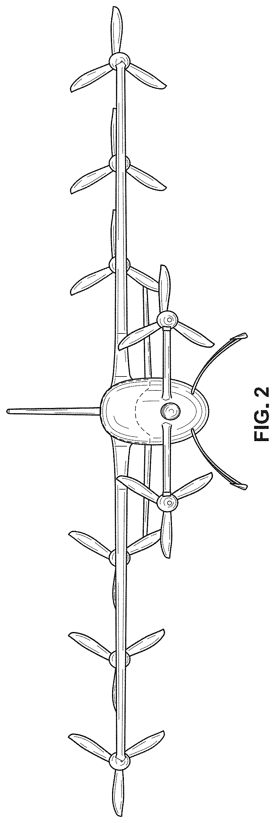
FIG. 2 is a front view of a fixed wing aircraft with tilt rotors showing our new design.
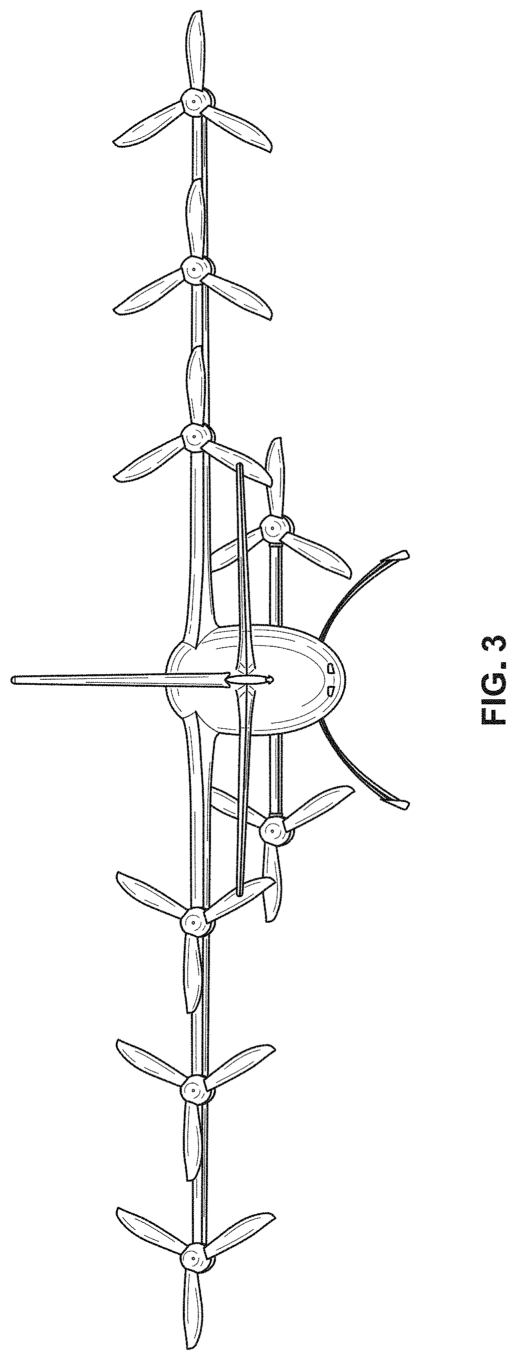
FIG. 3 is a back view of a fixed wing aircraft with tilt rotors showing our new design.
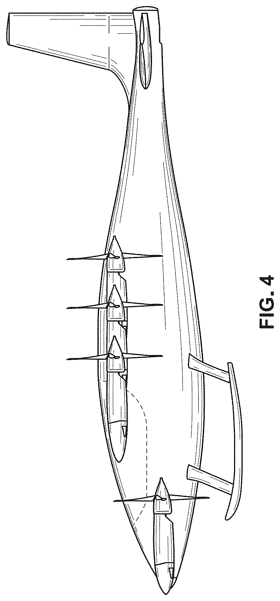
FIG. 4 is a left view of a fixed wing aircraft with tilt rotors showing our new design.
FIG. 5 is a right view of a fixed wing aircraft with tilt rotors showing our new design.
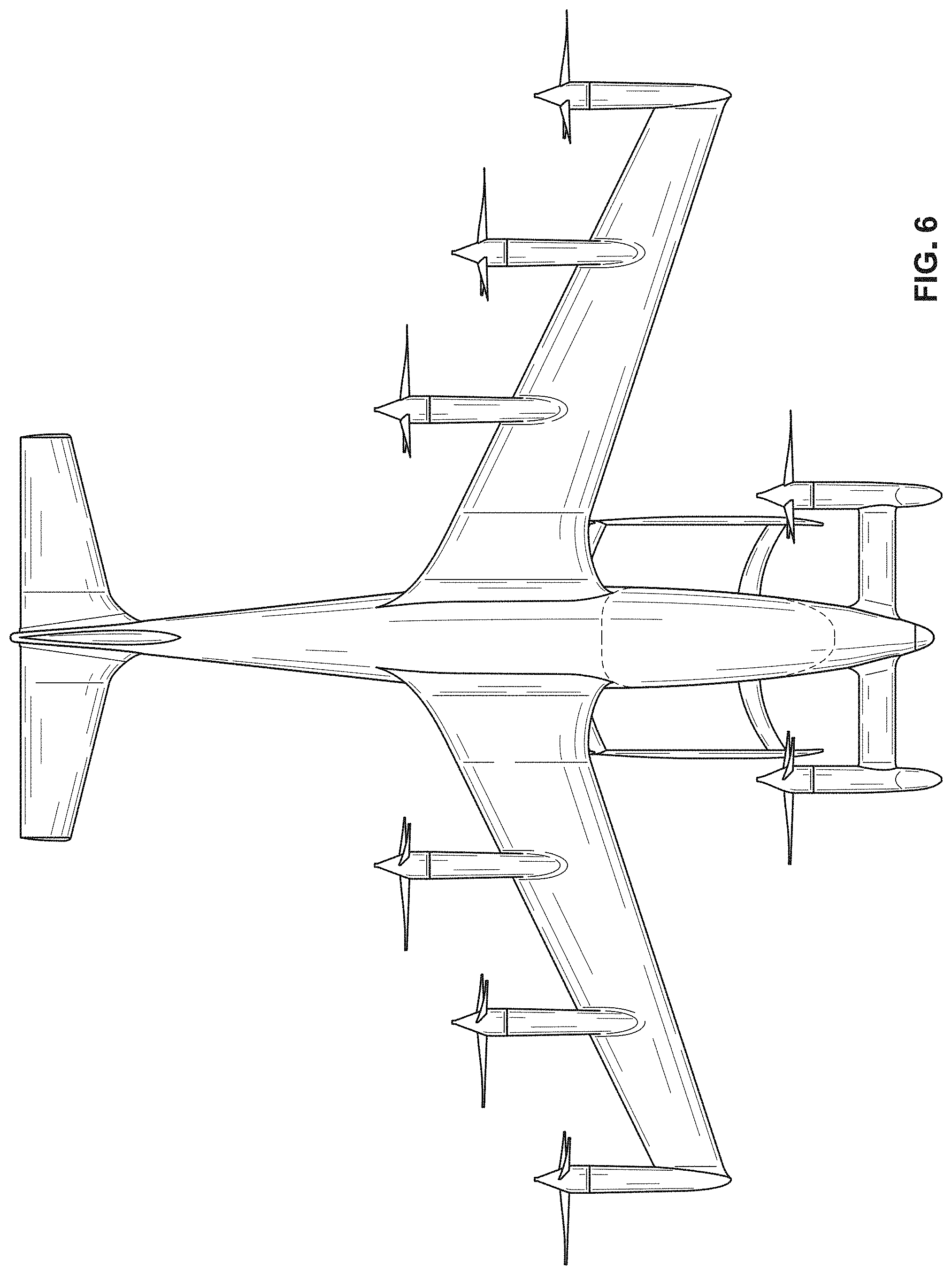
FIG. 6 is a top view of a fixed wing aircraft with tilt rotors showing our new design; and,
FIG. 7 is a bottom view of a fixed wing aircraft with tilt rotors showing our new design.
In the drawings, the broken lines depict portions of fixed wing aircraft with tilt rotors that forms no part of the claimed design.
* * * * *
D00000
D00001
D00002
D00003
D00004
D00005
D00006
D00007
XML
uspto.report is an independent third-party trademark research tool that is not affiliated, endorsed, or sponsored by the United States Patent and Trademark Office (USPTO) or any other governmental organization. The information provided by uspto.report is based on publicly available data at the time of writing and is intended for informational purposes only.
While we strive to provide accurate and up-to-date information, we do not guarantee the accuracy, completeness, reliability, or suitability of the information displayed on this site. The use of this site is at your own risk. Any reliance you place on such information is therefore strictly at your own risk.
All official trademark data, including owner information, should be verified by visiting the official USPTO website at www.uspto.gov. This site is not intended to replace professional legal advice and should not be used as a substitute for consulting with a legal professional who is knowledgeable about trademark law.