Pipe coupling
Lippka
U.S. patent number D889,611 [Application Number D/710,081] was granted by the patent office on 2020-07-07 for pipe coupling. This patent grant is currently assigned to Tyco Fire Products LP. The grantee listed for this patent is Tyco Fire Products LP. Invention is credited to Sandra M. Lippka.


View All Diagrams
| United States Patent | D889,611 |
| Lippka | July 7, 2020 |
Pipe coupling
Claims
CLAIM The ornamental design for a pipe coupling, as shown and described.
| Inventors: | Lippka; Sandra M. (Warwick, RI) | ||||||||||
|---|---|---|---|---|---|---|---|---|---|---|---|
| Applicant: |
|
||||||||||
| Assignee: | Tyco Fire Products LP
(Lansdale, PA) |
||||||||||
| Appl. No.: | D/710,081 | ||||||||||
| Filed: | October 21, 2019 |
Related U.S. Patent Documents
| Application Number | Filing Date | Patent Number | Issue Date | ||
|---|---|---|---|---|---|
| 29632434 | Jan 8, 2018 | D865919 | |||
| Current U.S. Class: | D23/262; D8/396 |
| Current International Class: | 2301 |
| Field of Search: | ;285/112,179,340,367,373,404,410-412,414-415,420 ;404/44,46,57,290,296,309,343-344 ;D23/259-260,262-266 |
References Cited [Referenced By]
U.S. Patent Documents
| D142057 | August 1945 | Baxter |
| D189229 | November 1960 | Bowne |
| D283486 | April 1986 | Fogel |
| D488852 | April 2004 | Pampinella |
| D536607 | February 2007 | Bekkevold |
| D577423 | September 2008 | Dole |
| D597635 | August 2009 | Dole |
| D598076 | August 2009 | Dole |
| D600325 | September 2009 | Porter et al. |
| D600784 | September 2009 | Henry et al. |
| D602127 | October 2009 | Shah et al. |
| D605734 | December 2009 | Henry et al. |
| D605735 | December 2009 | Shah et al. |
| D605736 | December 2009 | Porter et al. |
| D616532 | May 2010 | Madara et al. |
| D616533 | May 2010 | Bowman et al. |
| D618312 | June 2010 | Madara et al. |
| D618314 | June 2010 | Bowman et al. |
| D625785 | October 2010 | Madara et al. |
| D625786 | October 2010 | Bowman et al. |
| D629074 | December 2010 | Shah et al. |
| D629076 | December 2010 | Madara et al. |
| D629078 | December 2010 | Dole |
| D629080 | December 2010 | Dole et al. |
| D629082 | December 2010 | Dole et al. |
| D650889 | December 2011 | Van Walraven |
| D680630 | April 2013 | Beagen, Jr. |
| D813025 | March 2018 | Yesavage et al. |
| D823443 | July 2018 | Bancroft et al. |
| D836184 | December 2018 | Lippka |
| D836185 | December 2018 | Lippka |
| D839398 | January 2019 | Lippka |
| D839399 | January 2019 | Lippka |
| D850900 | June 2019 | Yesavage |
| D856123 | August 2019 | Bancroft |
| D861473 | October 2019 | Yesavage |
| D863051 | October 2019 | Bancroft |
| D863052 | October 2019 | Bancroft |
| 2008/0265568 | October 2008 | Bekkevold |
| 2012/0139236 | June 2012 | Novitsky et al. |
| 2014/0327238 | November 2014 | Bowman |
| 2015/0176728 | June 2015 | Bowman |
| 2016/0186902 | June 2016 | Lee |
| 2017/0328500 | November 2017 | Bowman et al. |
| 2017/0328505 | November 2017 | Sith et al. |
| 2018/0156362 | June 2018 | Takeda et al. |
| 2018/0163905 | June 2018 | Ohnemus et al. |
| 2018/0209567 | July 2018 | Brandt et al. |
| 2018/0347732 | December 2018 | Kang et al. |
Attorney, Agent or Firm: Foley & Lardner LLP
Description
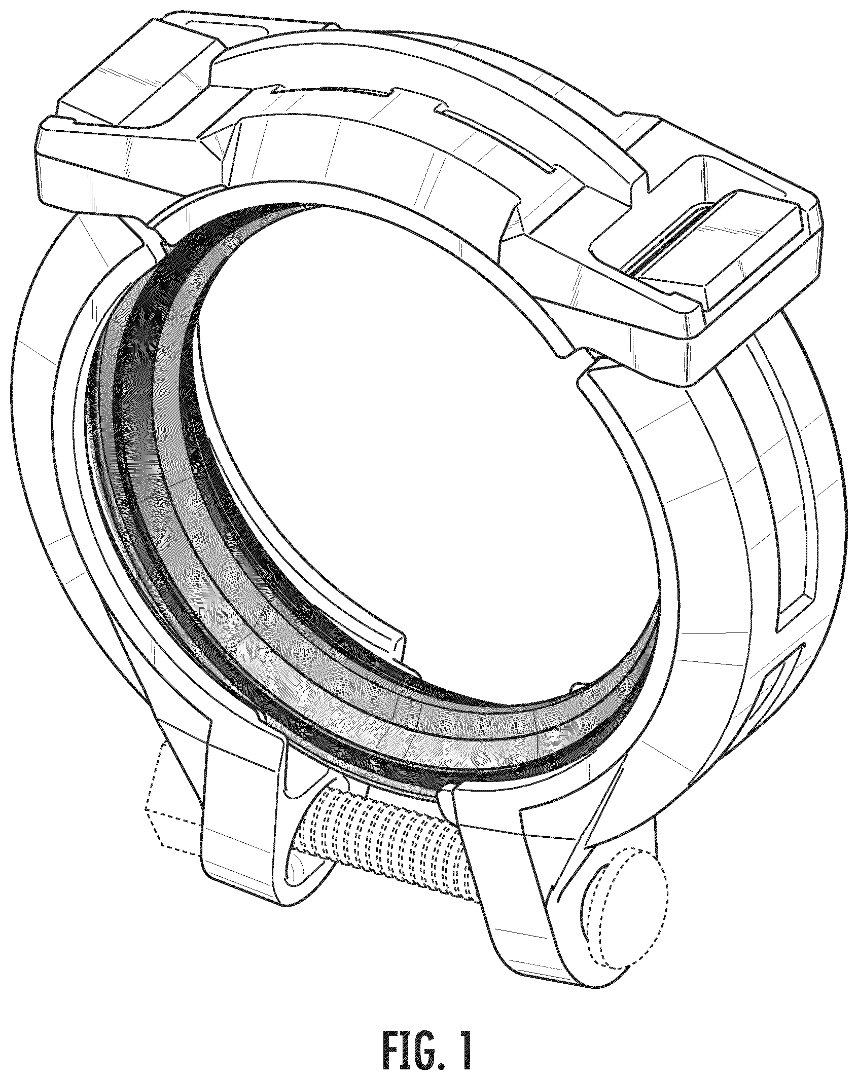
FIG. 1 is a perspective view showing a pipe coupling in accordance with a first embodiment of my new design;
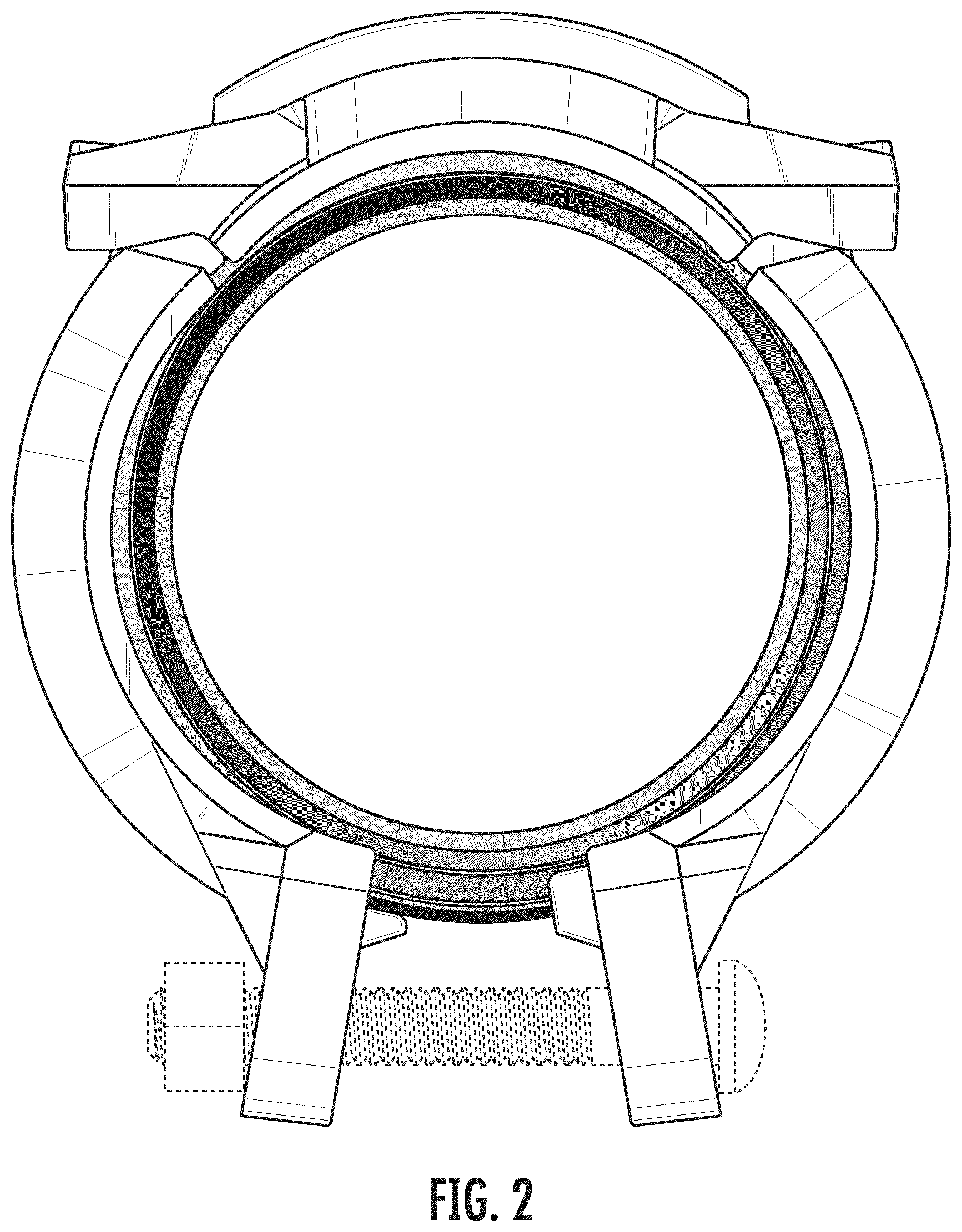
FIG. 2 is a front elevational view of the first embodiment;
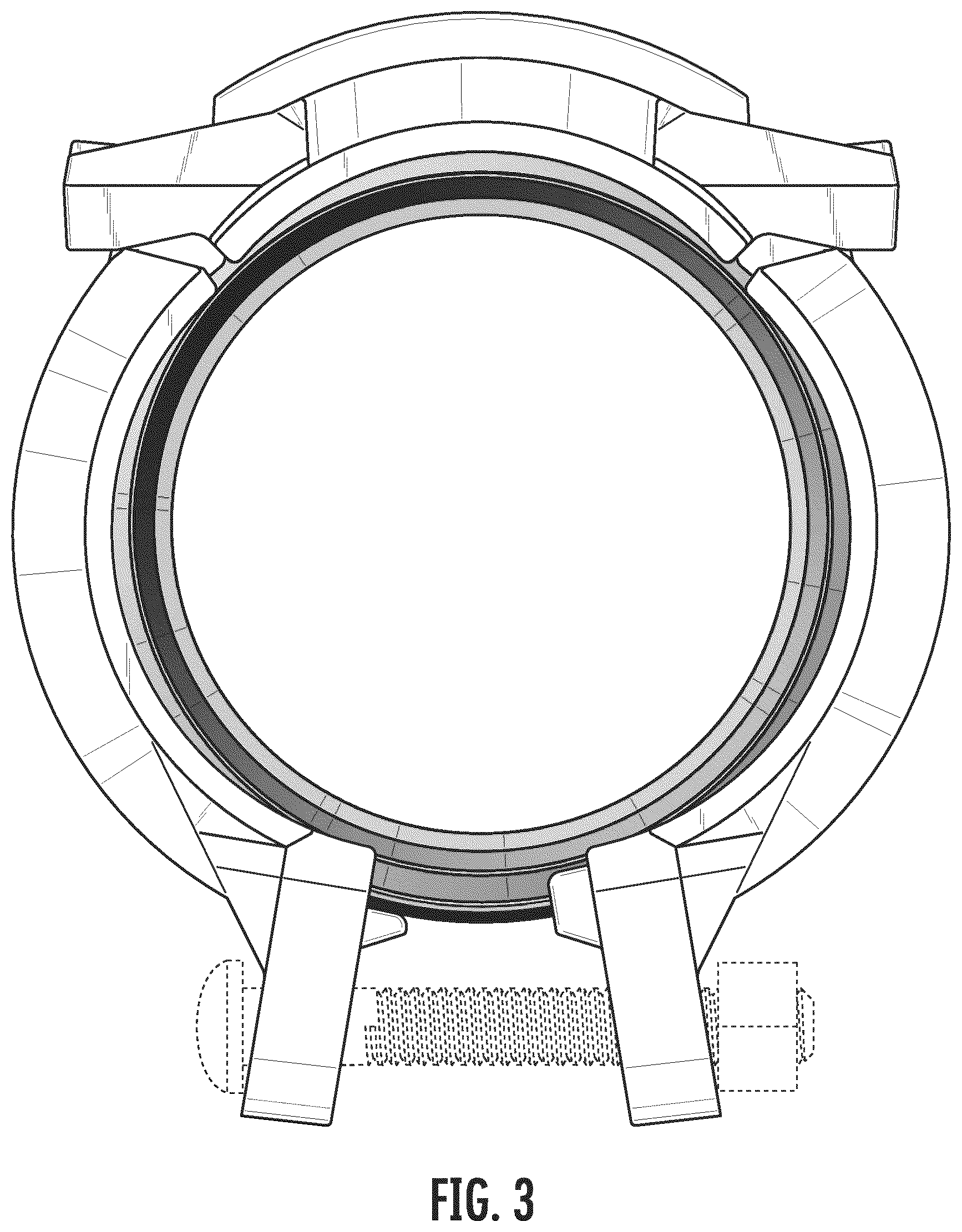
FIG. 3 is a rear elevational view of the first embodiment;
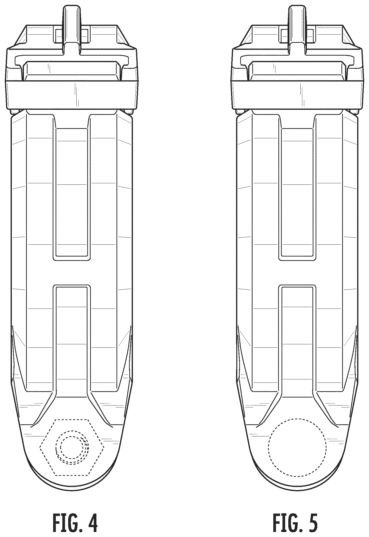
FIG. 4 is a right side elevational view of the first embodiment;
FIG. 5 is a left side elevational view of the first embodiment;
FIG. 6 is a top plan view of the first embodiment;
FIG. 7 is a bottom plan view of the first embodiment;
FIG. 8 is a perspective view showing a pipe coupling in accordance with a second embodiment of my new design;
FIG. 9 is a front elevational view of the second embodiment;
FIG. 10 is a rear elevational view of the second embodiment;
FIG. 11 is a right side elevational view of the second embodiment;
FIG. 12 is a left side elevational view of the second embodiment;
FIG. 13 is a top plan view of the second embodiment;
FIG. 14 is a bottom plan view of the second embodiment;
FIG. 15 is a perspective view showing a pipe coupling in accordance with a third embodiment of my new design;
FIG. 16 is a front elevational view of the third embodiment;
FIG. 17 is a rear elevational view of the third embodiment;
FIG. 18 is a right side elevational view of the third embodiment;
FIG. 19 is a left side elevational view of the third embodiment;
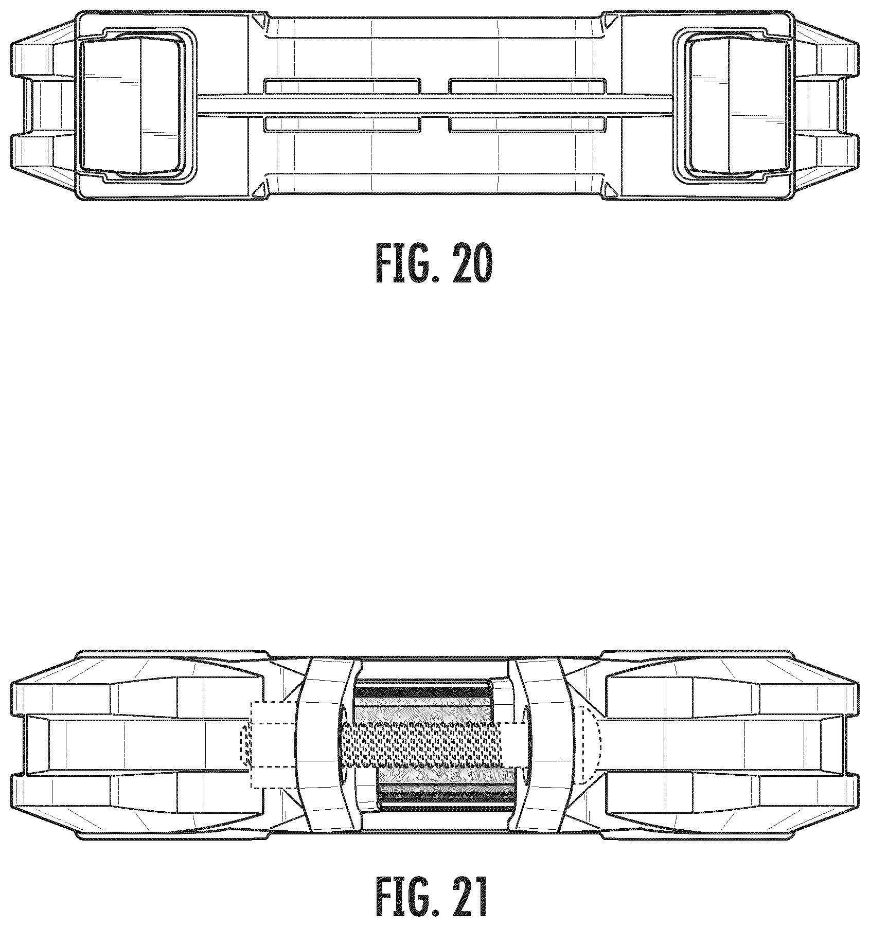
FIG. 20 is a top plan view of the third embodiment; and,
FIG. 21 is a bottom plan view of the third embodiment.
The broken lines shown in the drawings are for the purpose of illustrating portions of the pipe coupling that form no part of the claim.
* * * * *
D00000
D00001
D00002
D00003
D00004
D00005
D00006
D00007
D00008
D00009
D00010
D00011
D00012

D00013
D00014
D00015
XML
uspto.report is an independent third-party trademark research tool that is not affiliated, endorsed, or sponsored by the United States Patent and Trademark Office (USPTO) or any other governmental organization. The information provided by uspto.report is based on publicly available data at the time of writing and is intended for informational purposes only.
While we strive to provide accurate and up-to-date information, we do not guarantee the accuracy, completeness, reliability, or suitability of the information displayed on this site. The use of this site is at your own risk. Any reliance you place on such information is therefore strictly at your own risk.
All official trademark data, including owner information, should be verified by visiting the official USPTO website at www.uspto.gov. This site is not intended to replace professional legal advice and should not be used as a substitute for consulting with a legal professional who is knowledgeable about trademark law.