Vehicle fender
Metros , et al.
U.S. patent number D887,928 [Application Number D/673,780] was granted by the patent office on 2020-06-23 for vehicle fender. This patent grant is currently assigned to Ford Global Technologies, LLC. The grantee listed for this patent is Ford Global Technologies, LLC. Invention is credited to Darrell Behmer, Melvin Betancourt, Craig S. Metros, Christopher Stevens.


| United States Patent | D887,928 |
| Metros , et al. | June 23, 2020 |
Vehicle fender
Claims
CLAIM The ornamental design for a vehicle fender, as shown and described.
| Inventors: | Metros; Craig S. (Bloomfield, MI), Behmer; Darrell (Novi, MI), Betancourt; Melvin (Shelby Township, MI), Stevens; Christopher (Detroit, MI) | ||||||||||
|---|---|---|---|---|---|---|---|---|---|---|---|
| Applicant: |
|
||||||||||
| Assignee: | Ford Global Technologies, LLC
(Dearborn, MI) |
||||||||||
| Appl. No.: | D/673,780 | ||||||||||
| Filed: | December 18, 2018 |
| Current U.S. Class: | D12/184 |
| Current International Class: | 1216 |
| Field of Search: | ;D12/184,196,90-92,181 ;280/152.1,847-849,851 ;296/181.1,181.5 |
References Cited [Referenced By]
U.S. Patent Documents
| D567159 | April 2008 | Saridakis et al. |
| D607797 | January 2010 | Walter |
| D609150 | February 2010 | Krugger |
| D615013 | May 2010 | Lamm |
| D620407 | July 2010 | Froehlich |
| D665319 | August 2012 | Huet |
| D669405 | October 2012 | Gifford |
| D691530 | October 2013 | Song |
| D709010 | July 2014 | Mays et al. |
| D716708 | November 2014 | Beermann |
| D746742 | January 2016 | Curic et al. |
| D748023 | January 2016 | Nissl |
| D762151 | July 2016 | Luk |
| D763753 | August 2016 | Hammoud |
| D803119 | November 2017 | Beermann |
| D817829 | May 2018 | Behmer et al. |
| D826811 | August 2018 | Lim |
Other References
|
Reese Counts, 2020 Ford Shelby GT500 revealed in Instagram post, https://www.autoblog.com Oct 18, 2018. cited by applicant. |
Primary Examiner: Brown; Melody N.
Attorney, Agent or Firm: Chea; Vichit
Description
FIG. 1 is a front elevational view of a vehicle fender, showing our new design;
FIG. 2 is a left side elevational view thereof;
FIG. 3 is a right side elevational view thereof;
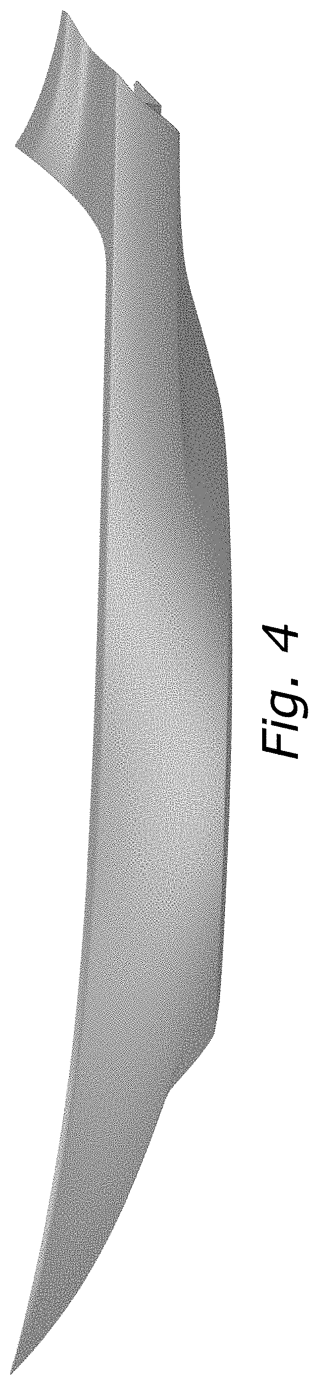
FIG. 4 is a top plan view thereof;
FIG. 5 is a bottom plan view thereof;
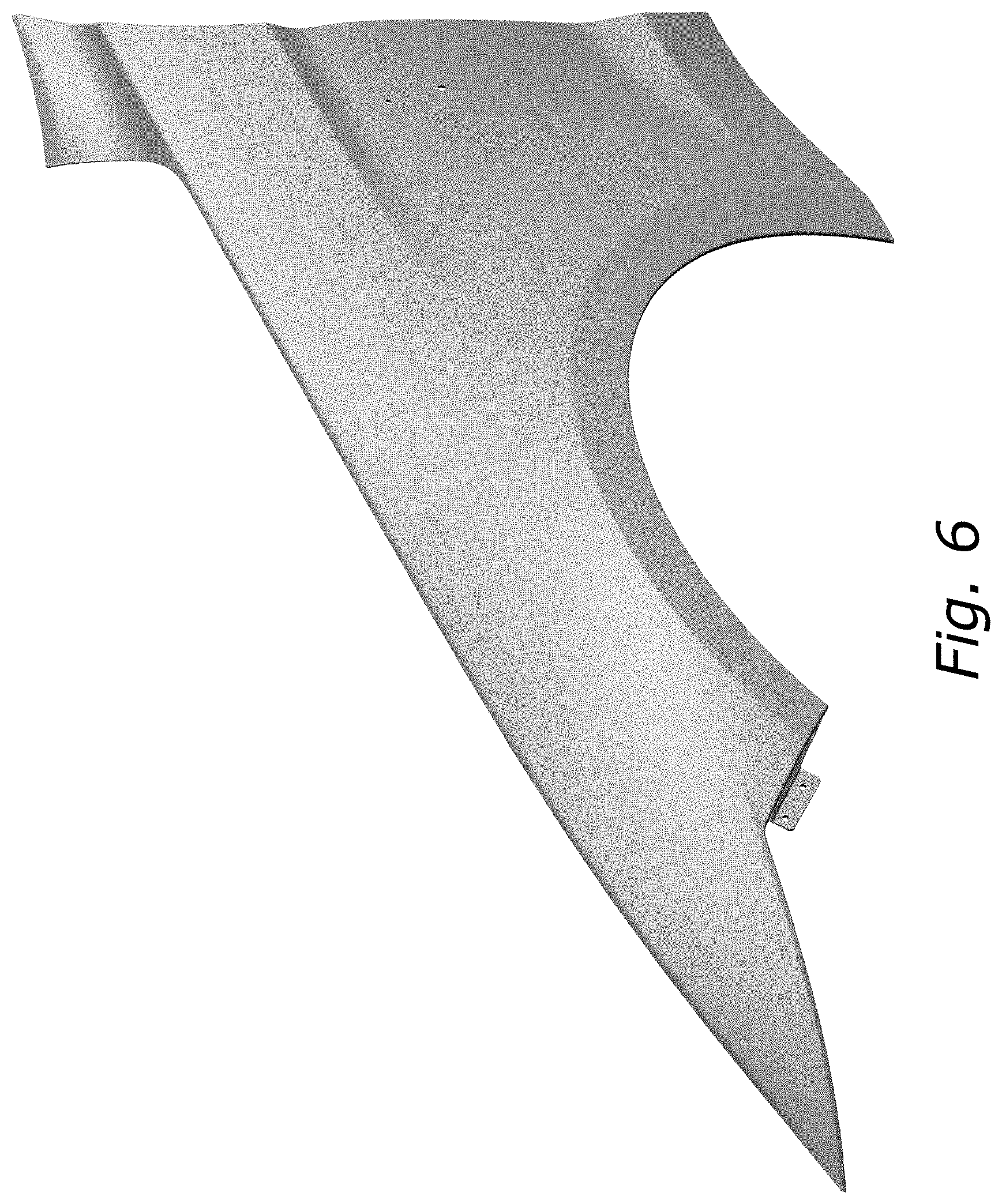
FIG. 6 is a top, front and left side perspective view thereof; and,
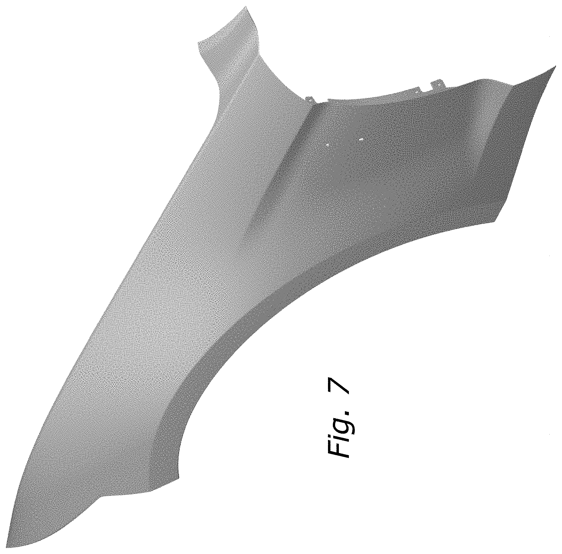
FIG. 7 is a front and right side perspective view thereof.
* * * * *
References
D00000
D00001
D00002
D00003
D00004
D00005
D00006
D00007
XML
uspto.report is an independent third-party trademark research tool that is not affiliated, endorsed, or sponsored by the United States Patent and Trademark Office (USPTO) or any other governmental organization. The information provided by uspto.report is based on publicly available data at the time of writing and is intended for informational purposes only.
While we strive to provide accurate and up-to-date information, we do not guarantee the accuracy, completeness, reliability, or suitability of the information displayed on this site. The use of this site is at your own risk. Any reliance you place on such information is therefore strictly at your own risk.
All official trademark data, including owner information, should be verified by visiting the official USPTO website at www.uspto.gov. This site is not intended to replace professional legal advice and should not be used as a substitute for consulting with a legal professional who is knowledgeable about trademark law.