Antenna
Ross, III , et al.
U.S. patent number D883,264 [Application Number D/713,645] was granted by the patent office on 2020-05-05 for antenna. This patent grant is currently assigned to Antennas Direct, Inc.. The grantee listed for this patent is Antennas Direct, Inc.. Invention is credited to John Edwin Ross, III, Richard E. Schneider.


View All Diagrams
| United States Patent | D883,264 |
| Ross, III , et al. | May 5, 2020 |
Antenna
Claims
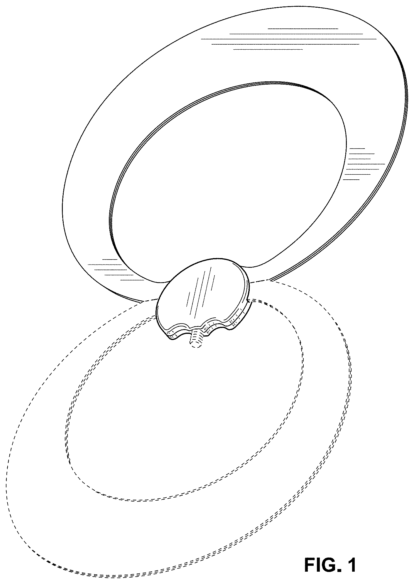
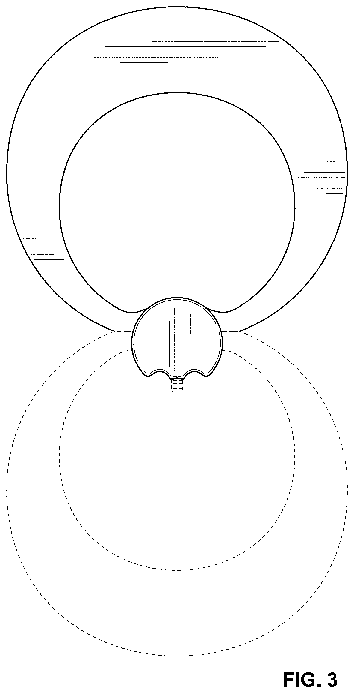
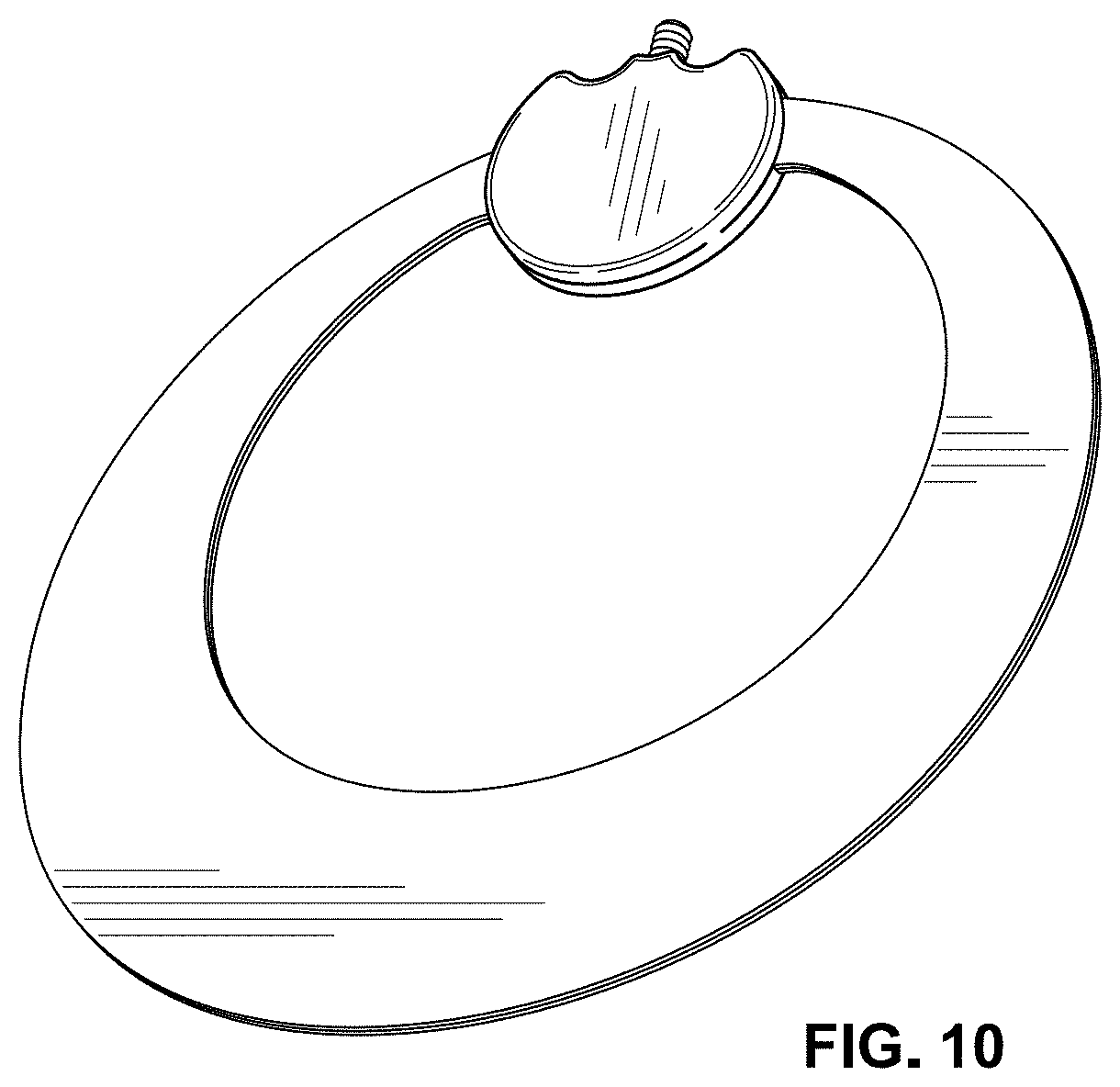
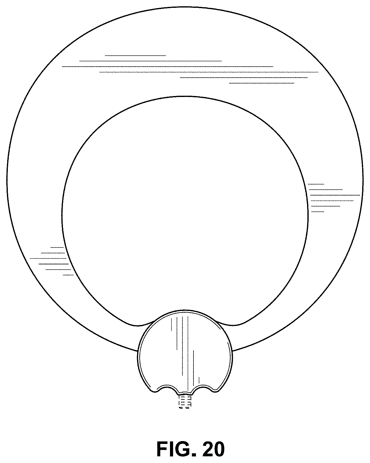
CLAIM The ornamental designs for an antenna, as shown and described.
| Inventors: | Ross, III; John Edwin (Moab, UT), Schneider; Richard E. (Wildwood, MO) | ||||||||||
|---|---|---|---|---|---|---|---|---|---|---|---|
| Applicant: |
|
||||||||||
| Assignee: | Antennas Direct, Inc.
(Ellisville, MO) |
||||||||||
| Appl. No.: | D/713,645 | ||||||||||
| Filed: | November 18, 2019 |
Related U.S. Patent Documents
| Application Number | Filing Date | Patent Number | Issue Date | ||
|---|---|---|---|---|---|
| 29671595 | Nov 28, 2018 | D867347 | |||
| 15685749 | Aug 24, 2017 | 10615501 | |||
| 14308422 | Jun 18, 2014 | ||||
| 29430632 | Aug 28, 2012 | ||||
| 29376791 | Oct 12, 2010 | D666178 | |||
| 13759750 | Feb 5, 2013 | 8994600 | |||
| 12606636 | Oct 27, 2009 | 8368607 | |||
| 12050133 | Mar 17, 2008 | 7609222 | |||
| 29304423 | Feb 29, 2008 | D598433 | |||
| 12040464 | Feb 29, 2008 | 7839347 | |||
| 29305294 | Mar 17, 2008 | D604276 | |||
| 12040464 | Feb 29, 2008 | 7839347 | |||
| 12050133 | Mar 17, 2008 | 7609222 | |||
| PCT/US2008/061908 | Apr 29, 2008 | ||||
| 12040464 | Feb 29, 2008 | 7839347 | |||
| 12050133 | Mar 17, 2008 | 7609222 | |||
| Current U.S. Class: | D14/230 |
| Current International Class: | 1403 |
| Field of Search: | ;D14/138,230-238,299,358 ;D12/42,43 |
References Cited [Referenced By]
U.S. Patent Documents
| 2060098 | November 1936 | Norman |
| 2220008 | October 1940 | Woodward et al. |
| 2437251 | March 1948 | Frische et al. |
| 2480155 | August 1949 | Masters |
| 2589578 | March 1952 | Sabins |
| D170203 | August 1953 | Leonard |
| D171560 | February 1954 | Ritter |
| D177200 | March 1956 | Valiulis |
| D179111 | November 1956 | Ballan |
| 2821710 | January 1958 | Hale |
| 3015101 | December 1961 | Turner et al. |
| 3123826 | March 1964 | Durham |
| 3161975 | December 1964 | McMillan |
| 3239838 | March 1966 | Kelleher |
| 3261019 | July 1966 | Lundy |
| 3273158 | September 1966 | Fouts et al. |
| D209402 | November 1967 | Burlingame |
| D211025 | May 1968 | Callaghan |
| 3434145 | March 1969 | Wells |
| 3521284 | July 1970 | Strom et al. |
| 3560983 | February 1971 | Willie et al. |
| 3587105 | June 1971 | Neilson |
| 3721990 | March 1973 | Gibson et al. |
| 3739388 | June 1973 | Callaghan |
| 3828867 | August 1974 | Elwood |
| 3971031 | July 1976 | Burke |
| 4183027 | January 1980 | Ehrenspeck |
| 4184163 | January 1980 | Woodward |
| 4418427 | November 1983 | Muterspaugh |
| D308521 | June 1990 | Lonczak |
| D310671 | September 1990 | Weiss |
| 4987424 | January 1991 | Tamura et al. |
| D318673 | July 1991 | Terk |
| D327690 | July 1992 | Ogawa et al. |
| D332262 | January 1993 | Borchardt |
| 5280645 | January 1994 | Nguyen et al. |
| D344731 | March 1994 | Witzky |
| D345982 | April 1994 | Lucey |
| 5313218 | May 1994 | Busking |
| 5943025 | August 1999 | Benham et al. |
| D414495 | September 1999 | Heiligenstein et al. |
| 5959586 | September 1999 | Benham et al. |
| D421610 | March 2000 | Ghalebi |
| 6054963 | April 2000 | Muterspaugh |
| 6239764 | May 2001 | Timofeev et al. |
| D449593 | October 2001 | Schultz |
| 6590541 | July 2003 | Schultze |
| 6593886 | July 2003 | Schantz |
| D480714 | October 2003 | Wang |
| 6680708 | January 2004 | Yamaki |
| D501468 | February 2005 | Wang |
| 6885352 | April 2005 | Lee et al. |
| 6917793 | July 2005 | Wang |
| 6922179 | July 2005 | McCollum |
| 7091925 | August 2006 | Wang |
| 7126556 | October 2006 | Wang |
| 7209089 | April 2007 | Schantz |
| D544471 | June 2007 | Wang |
| 7239290 | July 2007 | Poilasne et al. |
| 7245266 | July 2007 | Szente et al. |
| D558189 | December 2007 | Inoue |
| 7356362 | April 2008 | Chang et al. |
| 7436973 | October 2008 | Liao |
| D581931 | December 2008 | Pine |
| D585883 | February 2009 | Kaneko |
| D598433 | August 2009 | Schneider et al. |
| D598434 | August 2009 | Schneider et al. |
| D598469 | August 2009 | Harris, Jr. |
| 7609222 | October 2009 | Schneider et al. |
| D604276 | November 2009 | Schneider et al. |
| D611460 | March 2010 | Chao |
| 7693570 | April 2010 | Green et al. |
| D624531 | September 2010 | Fleck et al. |
| 7839347 | November 2010 | Schneider et al. |
| 7839351 | November 2010 | Schadler et al. |
| 7898496 | March 2011 | Olsen et al. |
| D638031 | May 2011 | Lee et al. |
| 7936311 | May 2011 | Rowser et al. |
| 7990335 | August 2011 | Schneider et al. |
| D655692 | March 2012 | Silverman et al. |
| 8144069 | March 2012 | Sadowski et al. |
| 8174457 | May 2012 | Lam |
| D664564 | July 2012 | Gillett et al. |
| D666178 | August 2012 | Schneider et al. |
| 8368607 | February 2013 | Schneider et al. |
| 8736500 | May 2014 | Lam |
| D721737 | January 2015 | Ahn et al. |
| 8994600 | March 2015 | Schneider |
| D809490 | February 2018 | Feit |
| D815073 | April 2018 | Feit |
| D824884 | August 2018 | Ross, III |
| D831010 | October 2018 | Yang |
| 10128575 | November 2018 | Ross, III et al. |
| D837769 | January 2019 | Yang |
| D838697 | January 2019 | Yang |
| D847798 | May 2019 | Yang |
| D849722 | May 2019 | Yang |
| D850425 | June 2019 | Yang |
| D867347 | November 2019 | Ross, III et al. |
| D868045 | November 2019 | Ross, III |
| D868720 | December 2019 | Feit et al. |
| 2002/0158798 | October 2002 | Chiang et al. |
| 2003/0071757 | April 2003 | Yamaki |
| 2004/0090379 | May 2004 | Fourdeux et al. |
| 2004/0090385 | May 2004 | Green |
| 2004/0113841 | June 2004 | Louzir et al. |
| 2004/0217912 | November 2004 | Mohammadian |
| 2005/0088342 | April 2005 | Parsche |
| 2005/0162332 | July 2005 | Schantz |
| 2005/0259023 | November 2005 | Wang |
| 2005/0280582 | December 2005 | Powell et al. |
| 2006/0033665 | February 2006 | Yang |
| 2006/0055618 | March 2006 | Poilasne et al. |
| 2006/0077115 | April 2006 | Oh et al. |
| 2006/0103577 | May 2006 | Lee |
| 2006/0164304 | July 2006 | Huang et al. |
| 2007/0069955 | March 2007 | McCorkle |
| 2007/0200769 | August 2007 | Nakano et al. |
| 2008/0040464 | February 2008 | Chia |
| 2008/0094291 | April 2008 | Bystrom et al. |
| 2008/0211720 | September 2008 | Hansen |
| 2008/0258980 | October 2008 | Chen et al. |
| 2008/0291345 | November 2008 | Schneider |
| 2009/0058732 | March 2009 | Nakano et al. |
| 2009/0073067 | March 2009 | Soler Castany et al. |
| 2009/0146899 | June 2009 | Schneider et al. |
| 2010/0085269 | April 2010 | Sadowski et al. |
| 2014/0292597 | October 2014 | Schneider et al. |
| 201243084 | May 2009 | CN | |||
| ZL2008200072832 | May 2009 | CN | |||
| ZL2008301199963 | May 2009 | CN | |||
| 101453057 | Jun 2009 | CN | |||
| ZL2008301199978 | Jul 2009 | CN | |||
| ZL2008300091398 | Sep 2009 | CN | |||
| 203707328 | Jul 2014 | CN | |||
| 000946587 | May 2008 | EM | |||
| 1555717 | Jul 2005 | EP | |||
| 1653560 | May 2006 | EP | |||
| 1753080 | Feb 2007 | EP | |||
| 2263360 | Jul 1993 | GB | |||
| D1213590 | Jun 2004 | JP | |||
| M249233 | Nov 2004 | TW | |||
| D112283 | Aug 2006 | TW | |||
| D119092 | Sep 2007 | TW | |||
| 200926506 | Jun 2009 | TW | |||
| D129744 | Jul 2009 | TW | |||
| D129745 | Jul 2009 | TW | |||
| D129746 | Jul 2009 | TW | |||
| WO-2009073249 | Jun 2009 | WO | |||
Other References
|
"Analog High-Definition Television System", Wikipedia: the Free Encyclopedia. Wikimedia Foundation, Inc. Oct. 12, 2016. Web. Mar. 16, 2017, 5 pages. cited by applicant . "Television Antenna", Wikipedia: The Free encyclopedia. Wikimedia Foundation, Inc. Mar. 13, 2017. Web. Mar. 15, 217, 6 pages. cited by applicant . A Broadband Eccentric Annular Slot Antenna, Young Hoon Suh and Ikmo Park, Department of Electrical Engineering, Ajou University, pp. 94-97, IEEE copyright notice 2001. cited by applicant . A Printed Crescent Patch Antenna for Ultrawideband Applications, Ntsanderh C. Azenui an H.Y.D. Yang, IEEE Antennas and Wireless Propragation Letters, vol. 6, 2007, pp. 113-116. cited by applicant . Antenna Engineering Handbook, 3rd Edition, Edited by Richard C. Johnson, McGraw Hill, 1993, pp. 5-13 to 5-16. cited by applicant . Antenna Theory: a. Review, Balanis, Proc. IEEE vol. 80 No. 1 Jan. 1992, 17 pages. cited by applicant . Antennas Direct. PF7 Picture Frame Antenna, Oct. 1. 2005, Antennas Direct, http://web.archive.org/web/2005100102653/http://antennasdirect.com/PF7.su- - b.--antenna.html. 1 page. cited by applicant . C. M. Shah, S. Siriam, M. Bhaskaran and A. Mitchell, "Large area metal-silicone flexible electronic structures," 2010 Conference on Optoelectronic and Microelectronic Materials and Devices, Canberra, ACT, 2010, pp. 187-188. cited by applicant . Chinese office action dated Nov. 4, 2015 for Chinese application No. 2014101113505 filed Feb. 7, 2014, published as CN103972657 on Aug. 6, 2014, which names the same inventors, Richard E. Schneider and John Edwin Ross III, as the instant application but is not related through a priority claim; 7 pages. cited by applicant . Clearstream.TM. 2V; http://www.antennasdirect.com/cmss.sub.--files/attachementlibrary/pdf/C2-- - V-.sub.--Qs.sub.--FINAL.sub.--20120702.pdf; Jul. 2, 2012; 2 pgs. cited by applicant . Design of Compact Components for Ultra Wideband Communication Front Ends. Marek Bialkowski, Amin Abbosh, and Hing Kan, School of Information Technology and Electrical Engineering, The University of Queensland, four pages. cited by applicant . European Search Report dated Apr. 24, 2014 for EP application No. 14153878.5 which claims priority to the instant application; 9 pages. cited by applicant . European Search Report dated Jan. 17, 2011, issued by the European Patent Office for European Patent Application No. EP 10193159.0 which is related to the instant application through a priority claim; (5 pages). cited by applicant . European Supplementary Search Report and Opinion dated Oct. 7, 2010, issued by the European Patent Office for European Patent Application No. EP 08747115 (6 pages). cited by applicant . Frequency--and Time-Domain Modeling of Tapered Loop Antennas in Ultra-Wideband Radio Systems, Shiou-Li Chen and Shau-Gang Mao, Graduate Institute of Computer and Communication Engineer, pp. 179-182, IEEE copyright notice 2006. cited by applicant . IEEE Spectrum: Antennas for the New Airwaves, http://www.spectrum.ieee.org/print/7328, Published Feb. 2009, 9 pages, Authors Richard Schneider and John Ross. cited by applicant . Mao S-G et al., "Time-domain characteristics of ultra-wideband tapered loop antennas", Electronics Letters, IEE Stevenage, GB, vol. 42, No. 22, Oct. 26, 2006; 1262-1264; 2 pages. cited by applicant . One-Element Loop Antenna with Finite Reflector, B. Rojarayanont and T. Sekiguchi, Electronics & Communications in Japan, vol. 59-B, No. 5, May 1976, p. 68. cited by applicant . Planar Miniature Tapered-Slot-Fed Annular Slot Antennas for Ultrawide-Band Radios, Tzyh-Ghuang Ma, Student Member, and Shyh-Kang, Jeng, Senior Member, IEEE, IEEE Transactions on Antennas and Propagation, vol. 53, No. 3, Mar. 2005, pp. 1194-1202. cited by applicant . Self-Mutual Admittances of Two Identical Circular Loop Antennas in a Conducting Medium and in Air, K. Iizuka, Senior Member, IEEE, R. W. P. King, Fellow, IEEE, and C. W. Harrison, Jr., Senior Member, IEEE, IEEE Transactions on Antennas andPropagation, vol. AP014, No. 4, Jul. 1966, pp. 440-450. cited by applicant . Tofel, Kevin C., HD Picture frame antenna, Aug. 11, 2005, http://hd.engadget.com/2005/08/11/hd-picture-frame-antenna, 1 page. cited by applicant. |
Primary Examiner: Windmuller; John
Attorney, Agent or Firm: Harness, Dickey & Pierce, P.L.C. Fussner; Anthony G.
Description
FIG. 1 is a perspective view of a first embodiment of an antenna, showing our new design;
FIG. 2 is a back perspective view of the antenna shown in FIG. 1;
FIG. 3 is a front elevation view of the antenna shown in FIG. 1;
FIG. 4 is a back elevation of the antenna shown in FIG. 1;
FIG. 5 is a right elevation view of the antenna shown in FIG. 1;
FIG. 6 is a left elevation view of the antenna shown in FIG. 1;
FIG. 7 is a top plan view of the antenna shown in FIG. 1;
FIG. 8 is a bottom plan view of the antenna shown in FIG. 1;
FIG. 9 is a perspective view of a second embodiment of an antenna, showing our new design;
FIG. 10 is a back perspective view of the antenna shown in FIG. 9;
FIG. 11 is a front elevation view of the antenna shown in FIG. 9;
FIG. 12 is a back elevation of the antenna shown in FIG. 9;
FIG. 13 is a right elevation view of the antenna shown in FIG. 9;
FIG. 14 is a left elevation view of the antenna shown in FIG. 9;
FIG. 15 is a top plan view of the antenna shown in FIG. 9;
FIG. 16 is a bottom plan view of the antenna shown in FIG. 9;
FIG. 17 is a perspective view of a third embodiment of an antenna, showing our new design;
FIG. 18 is a back perspective view of the antenna shown in FIG. 17;
FIG. 19 is a front elevation view of the antenna shown in FIG. 17;
FIG. 20 is a back elevation of the antenna shown in FIG. 17;
FIG. 21 is a right elevation view of the antenna shown in FIG. 17;
FIG. 22 is a left elevation view of the antenna shown in FIG. 17;
FIG. 23 is a top plan view of the antenna shown in FIG. 17;
FIG. 24 is a bottom plan view of the antenna shown in FIG. 17;
FIG. 25 is a perspective view of a fourth embodiment of an antenna, showing our new design;
FIG. 26 is a back perspective view of the antenna shown in FIG. 25;
FIG. 27 is a front elevation view of the antenna shown in FIG. 25;
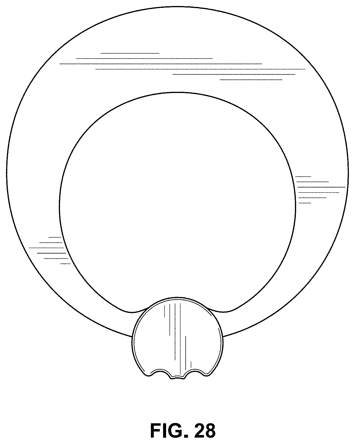
FIG. 28 is a back elevation of the antenna shown in FIG. 25;
FIG. 29 is a right elevation view of the antenna shown in FIG. 25;
FIG. 30 is a left elevation view of the antenna shown in FIG. 25;
FIG. 31 is a top plan view of the antenna shown in FIG. 25; and,
FIG. 32 is a bottom plan view of the antenna shown in FIG. 25.
In the drawings, the details shown in broken lines depict environmental subject matter only and form no part of the claimed design.
* * * * *
References
D00000
D00001
D00002
D00003
D00004
D00005
D00006
D00007
D00008
D00009
D00010
D00011
D00012

D00013

D00014
D00015

D00016

D00017

D00018

D00019
D00020

XML
uspto.report is an independent third-party trademark research tool that is not affiliated, endorsed, or sponsored by the United States Patent and Trademark Office (USPTO) or any other governmental organization. The information provided by uspto.report is based on publicly available data at the time of writing and is intended for informational purposes only.
While we strive to provide accurate and up-to-date information, we do not guarantee the accuracy, completeness, reliability, or suitability of the information displayed on this site. The use of this site is at your own risk. Any reliance you place on such information is therefore strictly at your own risk.
All official trademark data, including owner information, should be verified by visiting the official USPTO website at www.uspto.gov. This site is not intended to replace professional legal advice and should not be used as a substitute for consulting with a legal professional who is knowledgeable about trademark law.