Loader cab
Carlson , et al. Nov
U.S. patent number D868,121 [Application Number D/664,146] was granted by the patent office on 2019-11-26 for loader cab. This patent grant is currently assigned to Great Plains Manufacturing, Inc.. The grantee listed for this patent is Great Plains Manufacturing, Inc.. Invention is credited to Jason Carlson, Toshihiko Takemura.


| United States Patent | D868,121 |
| Carlson , et al. | November 26, 2019 |
Loader cab
Claims
CLAIM The ornamental design for a loader cab, as shown and described.
| Inventors: | Carlson; Jason (Lindsborg, KS), Takemura; Toshihiko (Grapevine, TX) | ||||||||||
|---|---|---|---|---|---|---|---|---|---|---|---|
| Applicant: |
|
||||||||||
| Assignee: | Great Plains Manufacturing,
Inc. (Salina, KS) |
||||||||||
| Appl. No.: | D/664,146 | ||||||||||
| Filed: | September 21, 2018 |
| Current U.S. Class: | D15/30 |
| Current International Class: | 1503 |
| Field of Search: | ;D15/10,22-26,28,30 ;180/89.1,89.12,89.13,900,9.1,9.2,9.62 ;37/379 ;414/694,699,722-724,660,685,698,719,743 |
References Cited [Referenced By]
U.S. Patent Documents
| D272071 | January 1984 | Baconet |
| 4705449 | November 1987 | Christianson |
| D297329 | August 1988 | Monehaie |
| D304589 | November 1989 | Lanphere |
| D321517 | November 1991 | Katoh |
| 5273340 | December 1993 | Nelson |
| D348270 | June 1994 | Lehmann-Brendel |
| 5427185 | June 1995 | Seal |
| D366267 | January 1996 | Lepoix |
| D376604 | December 1996 | Johnson |
| 5911624 | June 1999 | Stauffer |
| D424778 | May 2000 | Dahl |
| D446225 | August 2001 | Brandenburg, III |
| D450718 | November 2001 | Muraro |
| D453023 | January 2002 | Kaneko |
| D455763 | April 2002 | Brandenburg, III |
| D463461 | September 2002 | Yanagida |
| D463462 | September 2002 | Yanagida |
| D464662 | October 2002 | Dahl |
| D479536 | September 2003 | Dahl |
| D481044 | October 2003 | Tokach |
| D492327 | June 2004 | Albright |
| D497920 | November 2004 | Antonetti |
| D504136 | April 2005 | Albright |
| D531646 | November 2006 | McCarren, Jr. |
| D533569 | December 2006 | Mursch |
| D534927 | January 2007 | Mursch |
| D541826 | May 2007 | Brush |
| D549245 | August 2007 | Antonetti |
| D572277 | July 2008 | Pinther |
| D583835 | December 2008 | Sugiyama |
| D594480 | June 2009 | Gicquel |
| D600721 | September 2009 | Shimomura |
| D614674 | April 2010 | Hobenshield |
| D625741 | October 2010 | Seidel |
| D636795 | April 2011 | Yamamoto |
| D637630 | May 2011 | Yamamoto |
| D642205 | July 2011 | Yamamoto |
| D653173 | January 2012 | Dolesh |
| D654400 | February 2012 | Dolesh |
| D660881 | May 2012 | Bohme |
| D668693 | October 2012 | Ringer |
| D671566 | November 2012 | Fang |
| D684607 | June 2013 | Hagura |
| D687868 | August 2013 | Watson |
| D691924 | October 2013 | Smith |
| D707728 | June 2014 | Imashige |
| D714837 | October 2014 | Jacobsthal |
| D720370 | December 2014 | Carter |
| D749649 | February 2016 | McAdam |
| D751123 | March 2016 | Kazakoff |
| D762248 | July 2016 | Steinhardt |
| D773537 | December 2016 | Fiser |
| D774111 | December 2016 | Underhill |
| D774112 | December 2016 | Fiser |
| D775244 | December 2016 | Hart |
| D780231 | February 2017 | Saari |
| D780232 | February 2017 | Saari |
| D780235 | February 2017 | Kim |
| D784425 | April 2017 | Cooksey |
| D790598 | June 2017 | Furuki |
| D835160 | December 2018 | Jilbert |
| D849062 | May 2019 | Jilbert |
Other References
|
Mulch Cool Work Harder, Universal Hydraulic Oil Cooler, Owner's Manual, fae-group.com, FAE Land Clearing, 16 pages. cited by applicant . Code Part Manual PM-RAD-AUS for Auxiliary Oil Cooler Kit for Skid Steer, Ref. 600000416-00, No. ESPL0S0, 3 pages, Aug. 2, 2018. cited by applicant . Auxiliary Hudraulic Oil Cooler for Skid-steers, Loftness Cool Flow, loftness.com, Hector, Minnesota, 2 pages. cited by applicant . Loftness Universal Hydraulic Oil Cooler Owner's Manual, U.S. Appl. No. 50-403, N14882 Rev. E, 32 pages, May 2, 2017. cited by applicant. |
Primary Examiner: Goodwin; Mark A
Attorney, Agent or Firm: Hovey Williams LLP
Description
FIG. 1 is a top front perspective view of a loader cab according to our new design, wherein the loader cab is positioned on a loader machine and includes an oil cooler extending rearward therefrom;
FIG. 2 is a top front perspective view of the loader cab from FIG. 1;
FIG. 3 is a front elevation view of the loader cab of FIG. 2;
FIG. 4 is a left side elevation view of the loader cab of FIGS. 2-3, wherein a right side elevation view is a mirror image of the left side;
FIG. 5 is a rear elevation view of the loader cab of FIGS. 2-4;
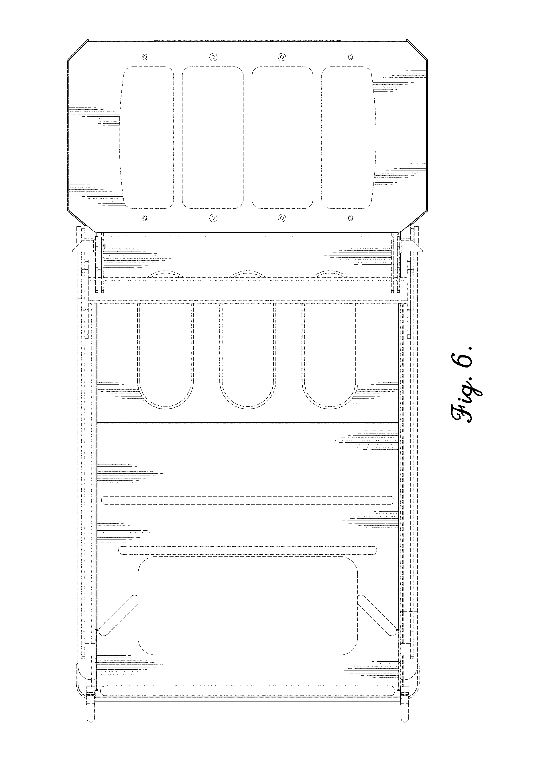
FIG. 6 is a top plan view of the loader cab of FIGS. 2-5; and,
FIG. 7 is a bottom plan view of the loader cab of FIGS. 2-6.
The broken lines shown in the various figures illustrate environment and portions of the loader cab that form no part of the claimed design.
* * * * *
D00000
D00001
D00002
D00003
D00004
D00005
D00006
D00007
XML
uspto.report is an independent third-party trademark research tool that is not affiliated, endorsed, or sponsored by the United States Patent and Trademark Office (USPTO) or any other governmental organization. The information provided by uspto.report is based on publicly available data at the time of writing and is intended for informational purposes only.
While we strive to provide accurate and up-to-date information, we do not guarantee the accuracy, completeness, reliability, or suitability of the information displayed on this site. The use of this site is at your own risk. Any reliance you place on such information is therefore strictly at your own risk.
All official trademark data, including owner information, should be verified by visiting the official USPTO website at www.uspto.gov. This site is not intended to replace professional legal advice and should not be used as a substitute for consulting with a legal professional who is knowledgeable about trademark law.