Sample holder for ionized sample analysis
Ohmura , et al. Nov
U.S. patent number D867,613 [Application Number D/656,981] was granted by the patent office on 2019-11-19 for sample holder for ionized sample analysis. This patent grant is currently assigned to HAMAMATSU PHOTONICS K.K.. The grantee listed for this patent is HAMAMATSU PHOTONICS K.K.. Invention is credited to Masahiro Kotani, Takayuki Ohmura.


View All Diagrams
| United States Patent | D867,613 |
| Ohmura , et al. | November 19, 2019 |
Sample holder for ionized sample analysis
Claims
CLAIM The ornamental design for a sample holder for ionized sample analysis, as shown and described.
| Inventors: | Ohmura; Takayuki (Hamamatsu, JP), Kotani; Masahiro (Hamamatsu, JP) | ||||||||||
|---|---|---|---|---|---|---|---|---|---|---|---|
| Applicant: |
|
||||||||||
| Assignee: | HAMAMATSU PHOTONICS K.K.
(Hamamatsu-shi, Shizuoka, JP) |
||||||||||
| Appl. No.: | D/656,981 | ||||||||||
| Filed: | July 18, 2018 |
Foreign Application Priority Data
| Jan 19, 2018 [JP] | 2018-000952 | |||
| Current U.S. Class: | D24/226; D10/103 |
| Current International Class: | 2402 |
| Field of Search: | ;D10/81,103 ;D24/224,225,226,227,229,230 |
References Cited [Referenced By]
U.S. Patent Documents
| D239548 | April 1976 | Schiff |
| D290042 | May 1987 | Ford |
| 5425451 | June 1995 | Blase |
| D376685 | December 1996 | Weller et al. |
| D418228 | December 1999 | Fisch |
| D431300 | September 2000 | Fisch |
| D431301 | September 2000 | Fisch |
| D510883 | October 2005 | George |
| 7217520 | May 2007 | Tsinberg |
| D702364 | April 2014 | Iqbal et al. |
| 9034634 | May 2015 | Miller |
| D733313 | June 2015 | Kouge et al. |
| D733912 | July 2015 | Ito et al. |
| D787356 | May 2017 | Johnston |
| D800336 | October 2017 | Chang et al. |
| D806892 | January 2018 | Walden, II et al. |
| D827857 | September 2018 | Buschtez |
| D838001 | January 2019 | Ito et al. |
| D840049 | February 2019 | Schulz et al. |
| D841183 | February 2019 | Walden, II et al. |
| D843013 | March 2019 | Ito et al. |
| D854184 | July 2019 | Ito et al. |
| D855203 | July 2019 | Katsumata et al. |
| D855206 | July 2019 | Ito et al. |
| D855207 | July 2019 | Ito et al. |
| D855208 | July 2019 | Ito et al. |
| D855209 | July 2019 | Ito et al. |
| D855210 | July 2019 | Ito et al. |
| 2015/0330776 | November 2015 | Hayashi et al. |
| 2016/0175840 | June 2016 | Ingber et al. |
Attorney, Agent or Firm: Drinker Biddle & Reath LLP
Description
FIG. 1 is a front view of a sample holder for ionized sample analysis of the present invention;
FIG. 2 is a rear view thereof;
FIG. 3 is a top plan view thereof;
FIG. 4 is a bottom plan view thereof;
FIG. 5 is a right side view thereof;
FIG. 6 is a left side view thereof;
FIG. 7 is a front perspective view thereof;
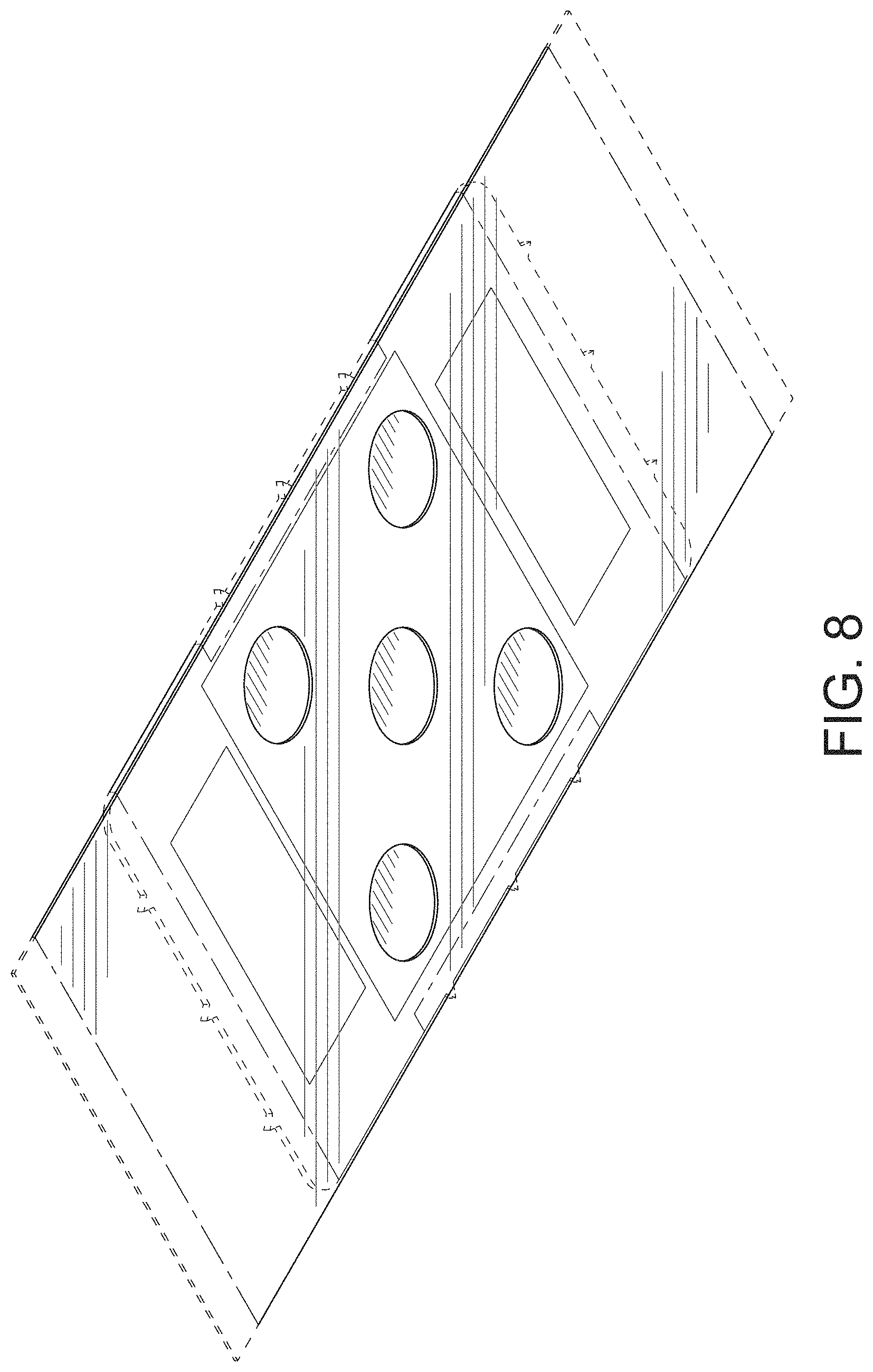
FIG. 8 is a rear perspective view thereof;
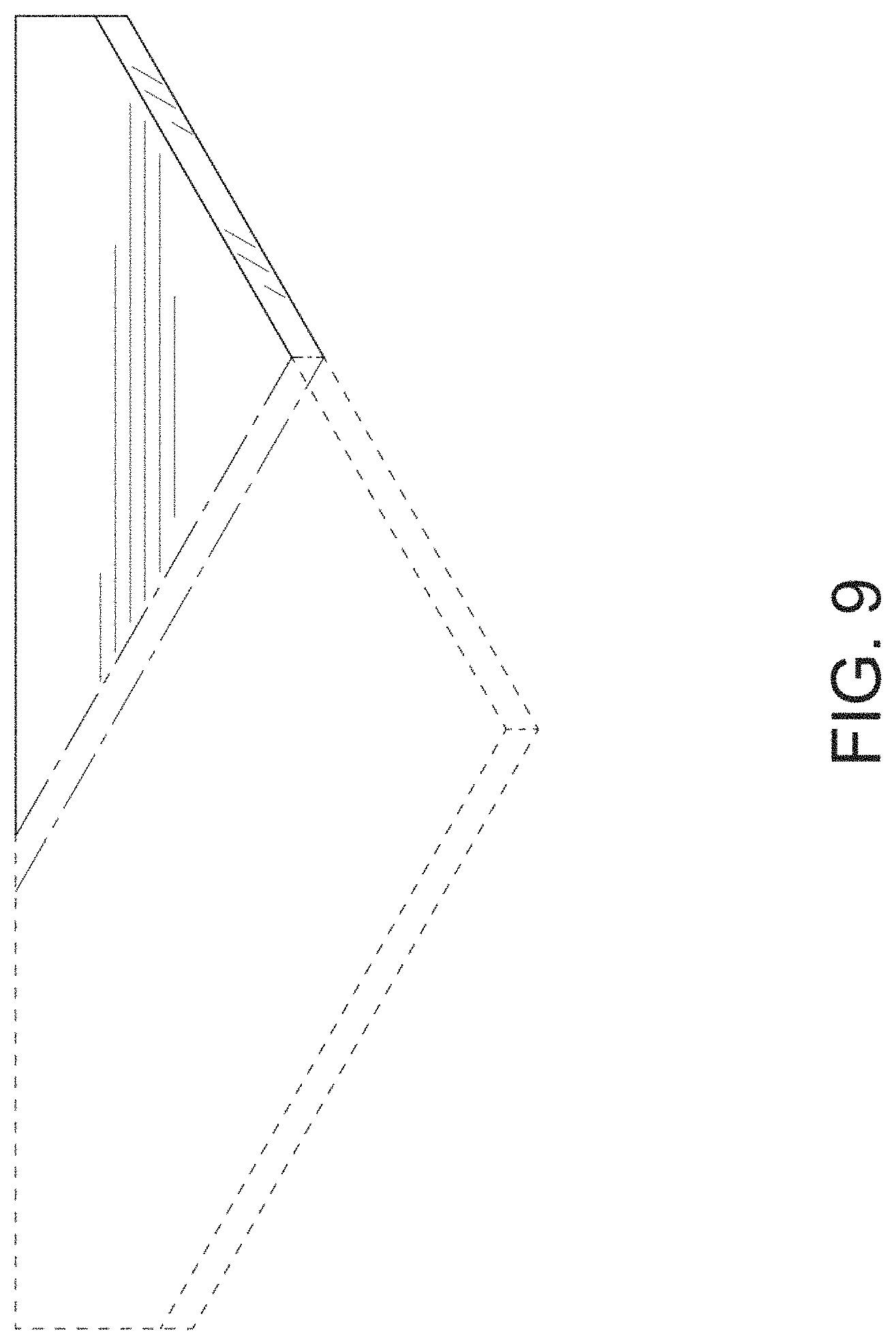
FIG. 9 is an enlarged view showing a portion of FIG. 7 defined by lines 9-9 and 9'-9';
FIG. 10 is an enlarged view showing a portion of FIG. 7 defined by lines 10-10 and 10'-10';
FIG. 11 is an enlarged view showing a portion of FIG. 7 defined by lines 11-11 and 11'-11';
FIG. 12 is a cross-sectional view along the line 12-12 in FIG. 3;
FIG. 13 is a top plan view of the main body;
FIG. 14 is a cross-sectional view along the line 14-14 in FIG. 3;
FIG. 15 is a top plan view of the separator;
FIG. 16 is an enlarged cross-sectional view along the line 16-16 in FIG. 1, in the area designated by 16'-16' in FIG. 1;
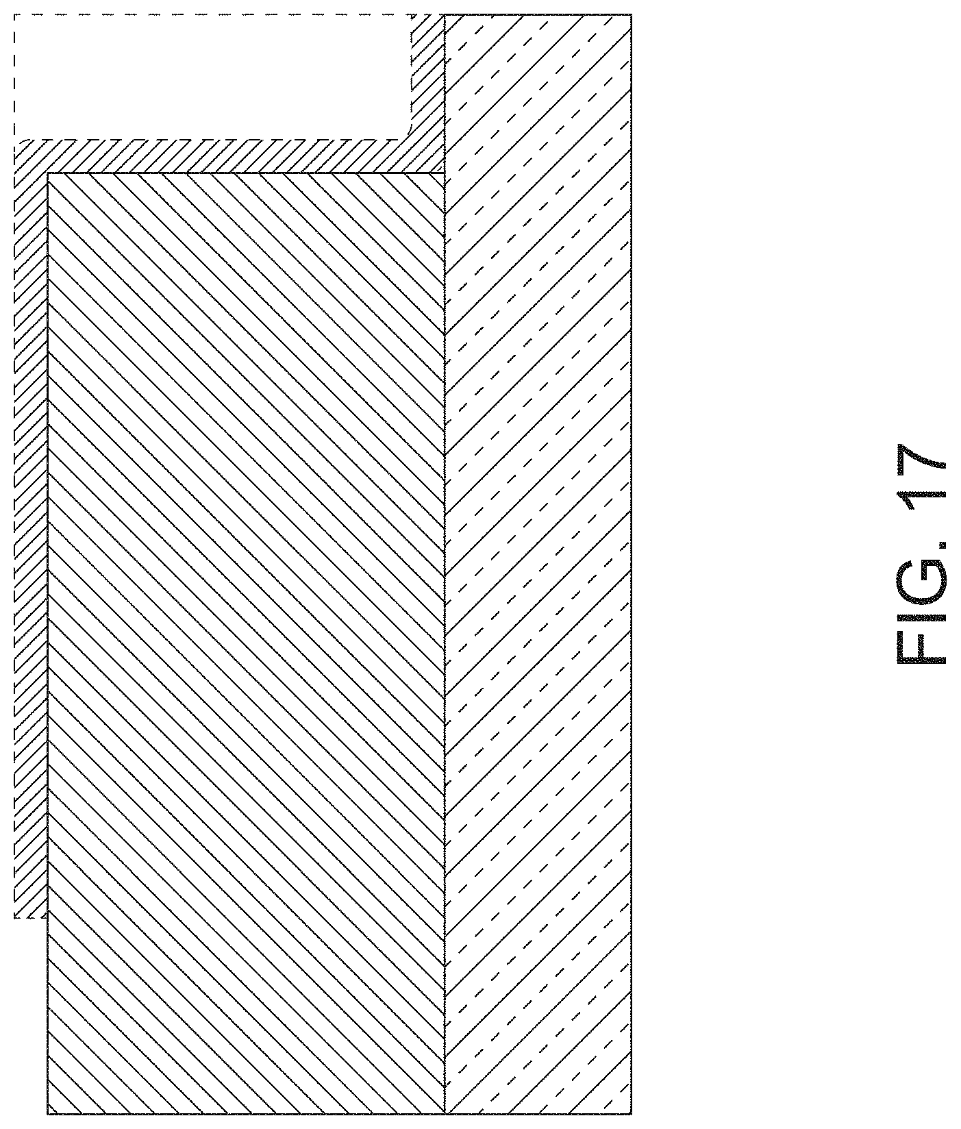
FIG. 17 is an enlarged cross-sectional view along the line 17-17 in FIG. 1, in the area designated by 17'-17' in. FIG. 1;
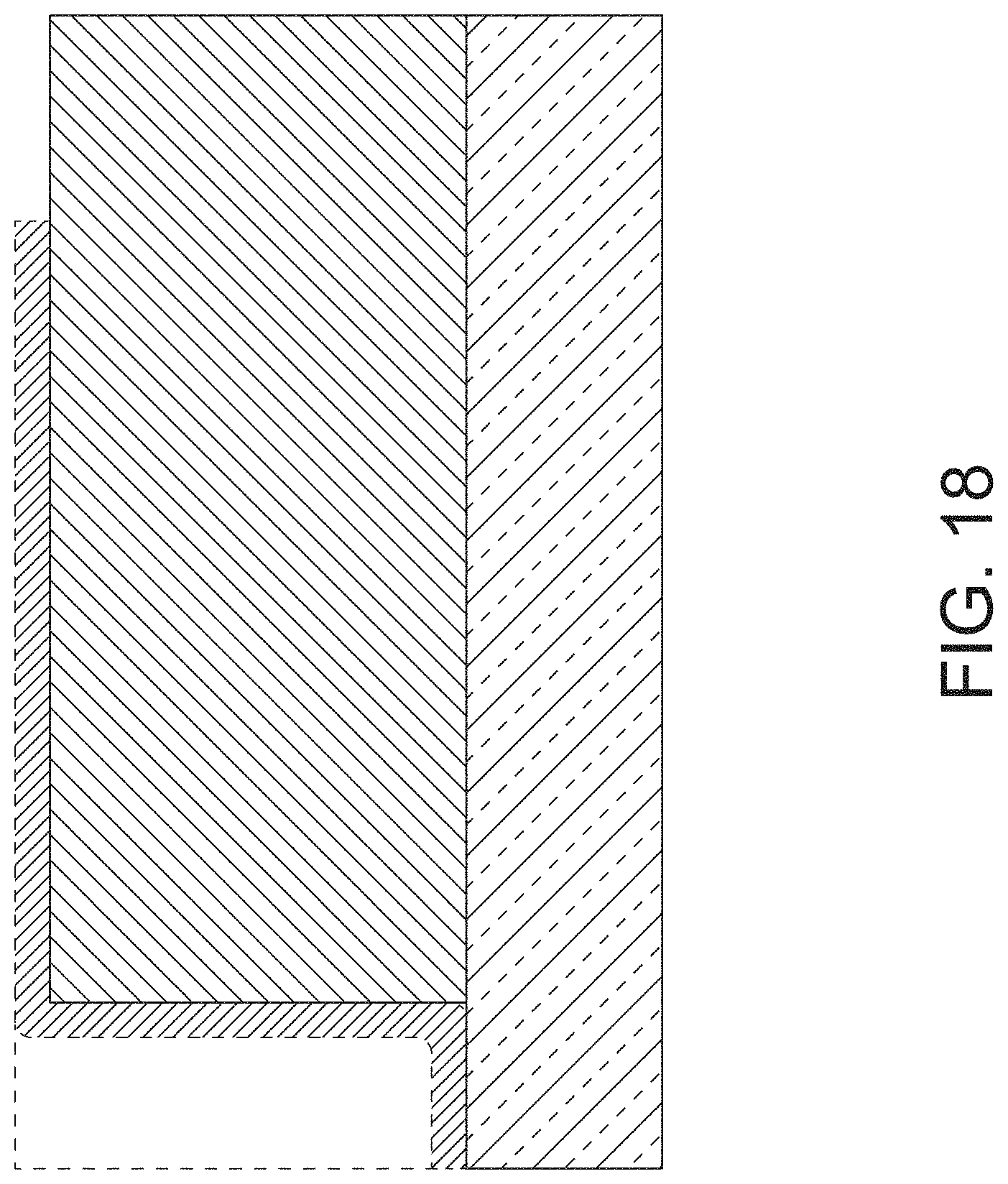
FIG. 18 is an enlarged cross-sectional view along the line 18-18 in FIG. 1, in the area designated by 18'-18' in FIG. 1;
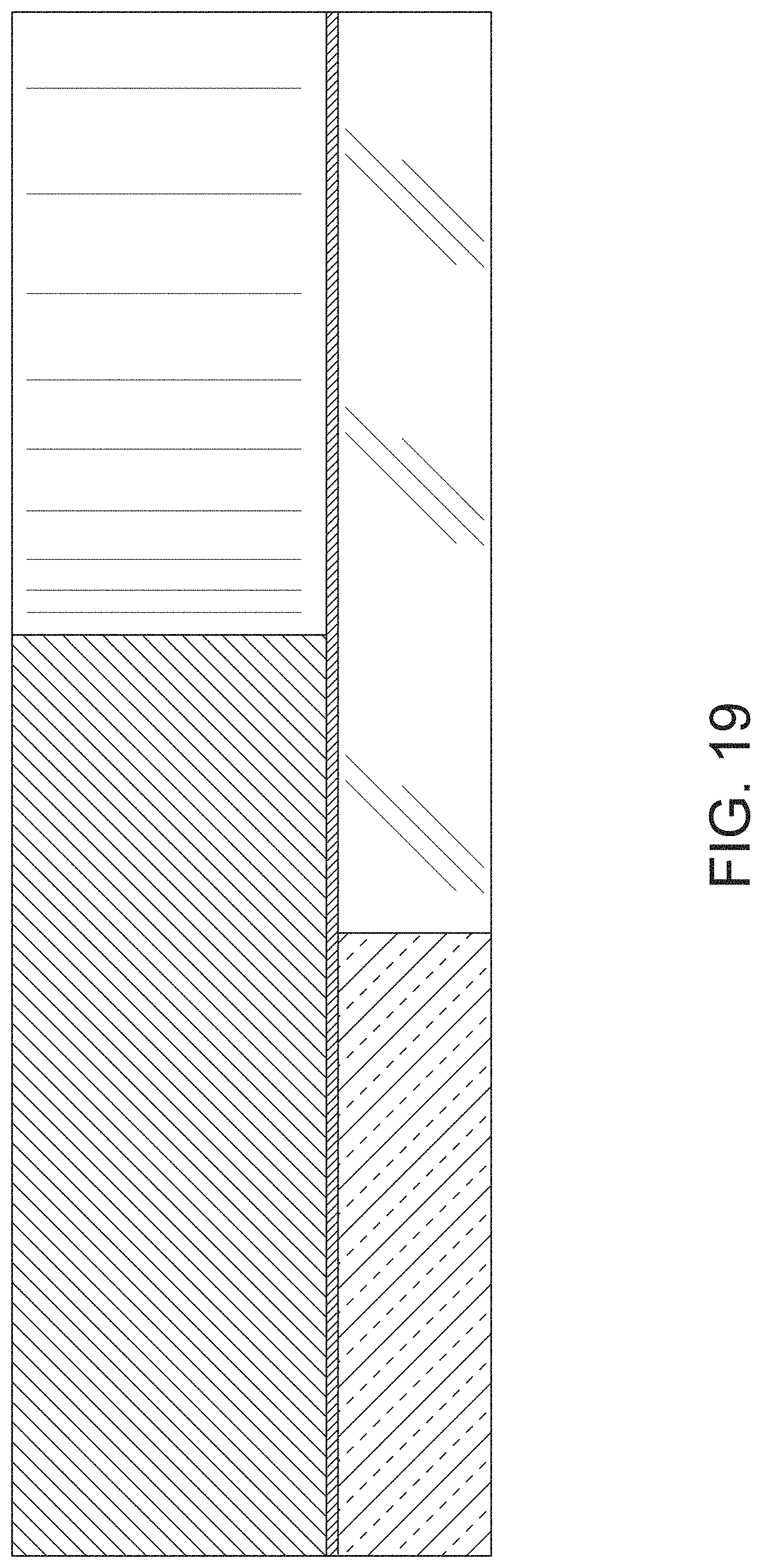
FIG. 19 is an enlarged cross-sectional view along the line 19-19 in FIG. 1, in the area designated by 19'-19' in FIG. 1; and,
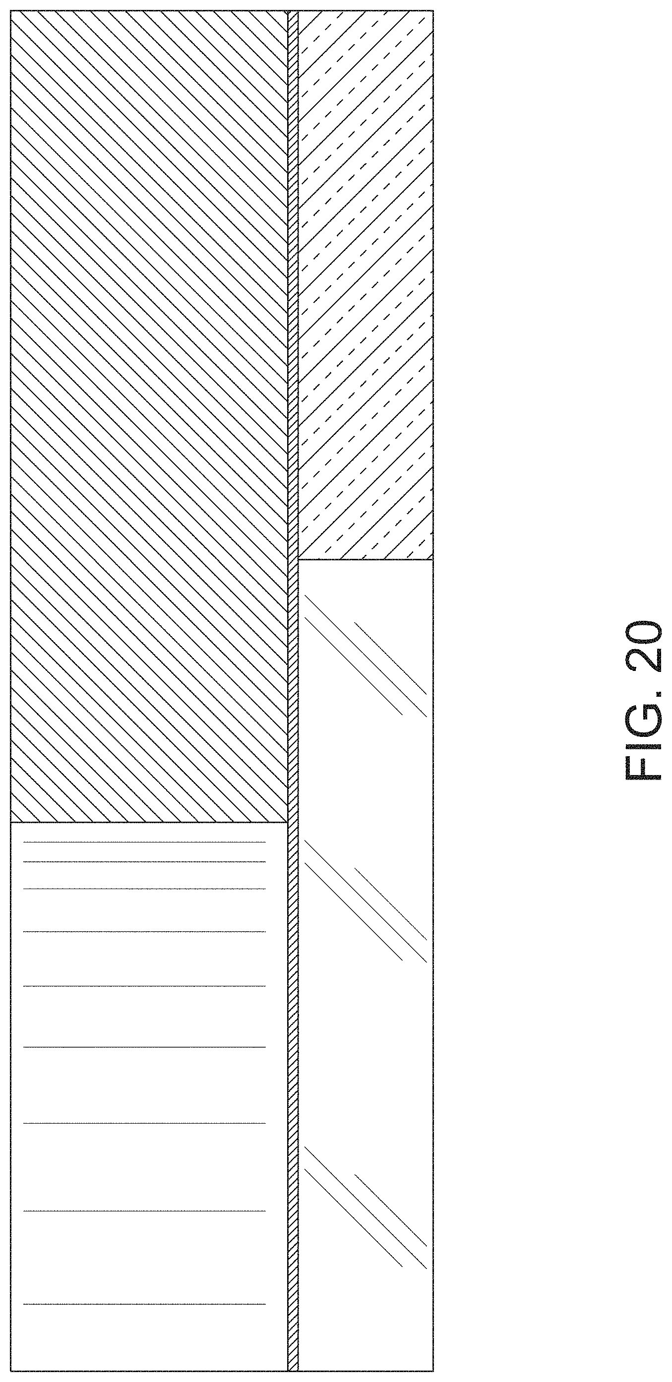
FIG. 20 is an enlarged cross-sectional view along the line 20-20 in FIG. 1, in the area designated by 20'-20' in FIG. 1.
The features shown in evenly-dashed broken lines depict environmental subject matter only and form no part of the claimed design. The dot-dash broken lines in the drawings represent the bounds of the claimed subject matter, the dot-dash broken lines, themselves forming no part thereof.
The portions shown in solid-broken alternated hatching lines in FIGS. 16 to 20 are transparent.
* * * * *
D00000
D00001
D00002
D00003
D00004
D00005
D00006
D00007
D00008
D00009
D00010
D00011
D00012

D00013

D00014

D00015

D00016

D00017
D00018
D00019
D00020
XML
uspto.report is an independent third-party trademark research tool that is not affiliated, endorsed, or sponsored by the United States Patent and Trademark Office (USPTO) or any other governmental organization. The information provided by uspto.report is based on publicly available data at the time of writing and is intended for informational purposes only.
While we strive to provide accurate and up-to-date information, we do not guarantee the accuracy, completeness, reliability, or suitability of the information displayed on this site. The use of this site is at your own risk. Any reliance you place on such information is therefore strictly at your own risk.
All official trademark data, including owner information, should be verified by visiting the official USPTO website at www.uspto.gov. This site is not intended to replace professional legal advice and should not be used as a substitute for consulting with a legal professional who is knowledgeable about trademark law.